

Page 1
B129/B130/B168/B169/B044/B045/B046
SERVICE MANUAL
001960MIU
RICOH GROUP COMPANIES
CÓPIA NÃO CONTROLADA
CÓPIA NÃO CONTROLADA
Page 2

CÓPIA NÃO CONTROLADA
CÓPIA NÃO CONTROLADA
Page 3

B129 SERIES/B044 SERIES
SERVICE MANUAL
RICOH GROUP COMPANIES
®
®
CÓPIA NÃO CONTROLADA
CÓPIA NÃO CONTROLADA
Page 4

CÓPIA NÃO CONTROLADA
CÓPIA NÃO CONTROLADA
Page 5

B129/B130/B168/B169/B044/B045/B046
SERVICE MANUAL
001960MIU
CÓPIA NÃO CONTROLADA
CÓPIA NÃO CONTROLADA
Page 6

CÓPIA NÃO CONTROLADA
CÓPIA NÃO CONTROLADA
Page 7

It is the reader's responsibility when discussing the information contained
within this document to maintain a level of confidentiality that is in the best
interest of Ricoh Corporation and its member companies.
NO PART OF THIS DOCUMENT MAY BE REPRODUCED IN ANY
FASHION AND DISTRIBUTED WITHOUT THE PRIOR
PERMISSION OF RICOH CORPORATION.
A
ll product names, domain names or product illustrations, including
desktop images, used in this document are trademarks, registered
trademarks or the property of their respective companies.
They are used throughout this book in an informational or editorial fashion
only and for the benefit of such companies. No such use, or the use o
f
any trade name, or web site is intended to convey endorsement or othe
r
affiliation with Ricoh products.
2004 RICOH Corporation. All rights reserved.
CÓPIA NÃO CONTROLADA
CÓPIA NÃO CONTROLADA
Page 8

CÓPIA NÃO CONTROLADA
CÓPIA NÃO CONTROLADA
Page 9

The Service Manual contains information
regarding service techniques, procedures,
p
rocesses and spare parts of office equipmen
t
distributed by Ricoh Corporation. Users of this
manual should be either service trained o
r
certified by successfully completing a Ricoh
Technical Training Program.
Untrained and uncertified users utilizin
g
information contained in this service manual to
repair or modify Ricoh equipment risk persona
l
injury, damage to property or loss of warrant
y
p
rotection.
Ricoh Corporation
WARNING
CÓPIA NÃO CONTROLADA
CÓPIA NÃO CONTROLADA
Page 10

CÓPIA NÃO CONTROLADA
CÓPIA NÃO CONTROLADA
Page 11

LEGEND
PRODUCT CODE COMPANY
GESTETNER LANIER RICOH SAVIN
B129 DSm415 LD015 Aficio 1515 3515
B130 DSm415pf LD015spf Aficio 1515MF 3515MF
B168 DSm415f LD015f Aficio 1515F 3515F
B169* * * * *
B044 1302 5613 Aficio 1013 2513
B045 --- --- Aficio 120 --B046 1302f 5613f Aficio 1013f 2513f
* This model is not currently available in the North or South American markets.
DOCUMENTATION HISTORY
REV. NO. DATE COMMENTS
*
10/2001 Original Printing
1 06/2004 B129/B130/B168/B169 Addition
2 04/2005 B129 Series Corrections
CÓPIA NÃO CONTROLADA
CÓPIA NÃO CONTROLADA
Page 12

CÓPIA NÃO CONTROLADA
CÓPIA NÃO CONTROLADA
Page 13

SM i B129 Series/B044 Series
B129/B130/B168/B169/B044/B045/B046
TABLE OF CONTENTS
INSTALLATION
1. INSTALLATION............................................................................ 1-1
1.1 INSTALLATION REQUIREMENTS ...........................................................1-1
1.1.1 ENVIRONMENT ...............................................................................1-1
1.1.2 MACHINE LEVEL.............................................................................1-2
1.1.3 MINIMUM OPERATIONAL SPACE REQUIREMENTS ....................1-2
1.1.4 POWER REQUIREMENTS ..............................................................1-3
1.2 COPIER.....................................................................................................1-4
1.2.1 ACCESSORY CHECK......................................................................1-4
B129 Basic Model.................................................................................1-4
B130 MFP Model ..................................................................................1-4
B168 Copier/Facsimile Model ............................................................... 1-5
B169 Copier/Printer/Scanner Model .....................................................1-5
1.2.2 INSTALLATION PROCEDURE ........................................................1-6
1.3 PAPER TRAY UNIT ................................................................................1-13
1.3.1 ACCESSORY CHECK....................................................................1-13
1.3.2 INSTALLATION PROCEDURE ......................................................1-14
1.4 PAPER TRAY UNIT HEATER .................................................................1-16
1.4.1 ACCESSORY CHECK....................................................................1-16
1.4.2 INSTALLATION PROCEDURE ......................................................1-17
1.5 DOCUMENT FEEDER (B696 AND B444)............................................... 1-22
1.5.1 ACCESSORY CHECK....................................................................1-22
1.5.2 INSTALLATION PROCEDURE ......................................................1-23
1.6 PRINTER SCANNER UNIT B683............................................................1-28
1.6.1 ACCESSORY CHECK....................................................................1-28
1.6.2 INSTALLATION PROCEDURE ......................................................1-29
1.7 POSTSCRIPT 3.......................................................................................1-34
1.8 IEEE 1284/IEEE 1394/BLUETOOTH INTERFACE .................................1-35
1.9 WIRELESS LAN ......................................................................................1-36
1.9.1 ACCESSORY CHECK....................................................................1-36
1.9.2 INSTALLATION PROCEDURE ......................................................1-36
1.10 BLUETOOTH.........................................................................................1-39
1.10.1 ACCESSORY CHECK..................................................................1-39
1.10.2 INSTALLATION PROCEDURE .................................................... 1-39
1.11 DIMM (B044/B045/B046 MODELS ONLY)............................................ 1-40
1.11.1 INSTALLATION PROCEDURE .................................................... 1-40
PREVENTIVE MAINTENANCE
2. PREVENTIVE MAINTENANCE.................................................... 2-1
2.1 PM TABLES ..............................................................................................2-1
CÓPIA NÃO CONTROLADA
CÓPIA NÃO CONTROLADA
Page 14

B129 Series/B044 Series ii SM
2.2 HOW TO CLEAR THE PM COUNTER......................................................2-2
REPLACEMENT AND ADJUSTMENT
3. REPLACEMENT AND ADJUSTMENT ........................................ 3-1
3.1 PRECAUTIONS.........................................................................................3-1
3.1.1 GENERAL ........................................................................................3-1
3.1.2 LITHIUM BATTERIES ......................................................................3-1
3.1.3 HALOGEN-FREE CABLE.................................................................3-1
3.1.4 PCU (PHOTOCONDUCTOR UNIT) .................................................3-1
3.1.5 TRANSFER ROLLER .......................................................................3-2
3.1.6 SCANNER UNIT............................................................................... 3-2
3.1.7 LASER UNIT ....................................................................................3-2
3.1.8 FUSING UNIT...................................................................................3-2
3.1.9 PAPER FEED...................................................................................3-3
3.2 SPECIAL TOOLS AND LUBRICANTS ......................................................3-3
3.3 EXTERIOR COVER AND OPERATION PANEL .......................................3-4
3.3.1 PLATEN COVER..............................................................................3-4
3.3.2 REAR COVER..................................................................................3-4
3.3.3 COPY TRAY.....................................................................................3-5
3.3.4 SCALE PLATE .................................................................................3-5
3.3.5 OPERATION PANEL AND UPPER COVERS..................................3-6
3.3.6 RIGHT DOOR...................................................................................3-7
3.3.7 BYPASS TRAY................................................................................. 3-7
3.3.8 PLATEN COVER SENSOR..............................................................3-8
3.4 SCANNER UNIT........................................................................................3-9
3.4.1 EXPOSURE GLASS.........................................................................3-9
Non-ADF machines...............................................................................3-9
ADF-equipped machines ......................................................................3-9
3.4.2 LENS BLOCK .................................................................................3-10
3.4.3 EXPOSURE LAMP, LAMP STABILIZER BOARD ..........................3-10
3.4.4 SCANNER MOTOR........................................................................3-11
3.4.5 SCANNER HP SENSOR ................................................................ 3-11
3.4.6 SCANNER ALIGNMENT ADJUSTMENT .......................................3-12
3.5 FUSING...................................................................................................3-13
3.5.1 FUSING UNIT................................................................................. 3-13
3.5.2 EXIT SENSOR ...............................................................................3-13
3.5.3 HOT ROLLER STRIPPER PAWLS ................................................3-14
3.5.4 HOT ROLLER & FUSING LAMP ....................................................3-15
3.5.5 THERMO-SWITCH AND THERMISTOR........................................3-16
3.5.6 PRESSURE ROLLER.....................................................................3-17
3.5.7 ADJUSTING NIP BAND .................................................................3-18
3.5.8 DUPLEX MOTOR...........................................................................3-19
3.5.9 CONTACT-RELEASE SOLENOID .................................................3-19
3.6 PCU AND QUENCHING LAMP...............................................................3-20
3.6.1 PCU ................................................................................................3-20
3.6.2 QUENCHING LAMP .......................................................................3-21
3.7 TONER SUPPLY CLUTCH .....................................................................3-22
CÓPIA NÃO CONTROLADA
CÓPIA NÃO CONTROLADA
Page 15

SM iii B129 Series/B044 Series
3.8 HIGH-VOLTAGE POWER SUPPLY BOARD ..........................................3-22
3.9 EXHAUST FAN AND MAIN MOTOR.......................................................3-23
3.9.1 EXHAUST FAN ..............................................................................3-23
3.9.2 MAIN MOTOR ................................................................................ 3-23
3.10 PAPER FEED........................................................................................3-24
3.10.1 PAPER FEED ROLLER AND FRICTION PAD.............................3-24
3.10.2 PAPER END SENSOR.................................................................3-24
3.10.3 REGISTRATION SENSOR...........................................................3-25
3.10.4 BYPASS PAPER END SENSOR..................................................3-25
3.10.5 BYPASS FEED ROLLER .............................................................3-26
3.10.6 BYPASS FEED CLUTCH AND FRICTION PAD ..........................3-27
3.10.7 PAPER FEED AND REGISTRATION CLUTCHES ......................3-28
3.11 IMAGE TRANSFER...............................................................................3-29
3.11.1 TRANSFER ROLLER ...................................................................3-29
3.11.2 ID SENSOR AND DUPLEX ROLLER...........................................3-29
3.11.3 DISCHARGE PLATE .................................................................... 3-30
3.12 CONTROLLER BOX AND BICU (B129/B130/B168/B169).................... 3-31
3.13 FUNCTION CONTROL UNIT (B044/B045/B046)..................................3-33
3.14 LASER UNIT .........................................................................................3-34
3.14.1 LOCATION OF CAUTION DECAL ...............................................3-34
3.14.2 PSU ..............................................................................................3-35
3.14.3 LASER UNIT ................................................................................3-36
3.14.4 LD UNIT AND POLYGON MIRROR MOTOR...............................3-36
3.15 ADJUSTING COPY IMAGE AREA........................................................3-37
3.15.1 PRINTING ....................................................................................3-37
Adjusting Registration .........................................................................3-37
Adjusting Blank Margin .......................................................................3-38
Adjusting Main-Scan Magnification .....................................................3-38
3.15.2 SCANNING...................................................................................3-39
Adjusting Registration .........................................................................3-39
Adjusting Magnification .......................................................................3-39
Standard White Density Adjustment ...................................................3-40
3.15.3 ADF IMAGE ADJUSTMENT.........................................................3-41
TROUBLESHOOTING
4. TROUBLESHOOTING ................................................................. 4-1
4.1 SERVICE CALL CONDITIONS .................................................................4-1
4.1.1 SUMMARY .......................................................................................4-1
4.1.2 SC CODE DESCRIPTIONS .............................................................4-2
B129/B130/B168/B169 UNIQUE ..........................................................4-2
B044/B045/B046 UNIQUE..................................................................4-11
ALL OTHER CODES FOR: (B129/B130/B168/B044/B045/B046) ...... 4-10
4.2 ELECTRICAL COMPONENT DEFECTS ................................................4-17
4.2.1 SENSOR/SWITCH OPEN ERRORS (B129/B130/B168/B169) ...... 4-17
4.2.2 SENSOR/SWITCH OPEN ERRORS (B044/B045/B046)................4-18
4.2.3 BLOWN FUSE CONDITIONS ........................................................4-19
CÓPIA NÃO CONTROLADA
CÓPIA NÃO CONTROLADA
Page 16

B129 Series/B044 Series iv SM
4.3 LED DISPLAY .........................................................................................4-19
4.3.1 BICU (B129/B130/B168/B169) ....................................................... 4-19
4.4 DUMPING THE FUSER TEMPERATURE LOG......................................4-19
SERVICE TABLES
5. SERVICE TABLES....................................................................... 5-1
5.1 SERVICE PROGRAM ............................................................................... 5-1
5.1.1 USING SP AND SSP MODES.......................................................... 5-1
Starting SP Mode..................................................................................5-1
Starting SSP Mode(B130/B168/B169) ..................................................5-2
Selecting Programs...............................................................................5-2
Specifying Values .................................................................................5-2
Activating Copy Mode ...........................................................................5-2
Quitting Programs/Ending (S)SP Mode ................................................5-2
5.1.2 SP MODE TABLES (B129)...............................................................5-3
SP1-XXX (Feed) ...................................................................................5-3
SP2-XXX (Drum)...................................................................................5-5
SP4-XXX (Scanner) ..............................................................................5-9
SP5-XXX (Mode) ................................................................................5-13
SP6-XXX (Peripherals) .......................................................................5-16
SP7-XXX (Data Log)...........................................................................5-17
SP8-XXX (History) ..............................................................................5-20
5.1.3 SP MODE TABLES (B130/B168/B169) .......................................... 5-22
SP1-XXX (Feed) .................................................................................5-22
SP2-XXX (Drum).................................................................................5-24
SP4-XXX (Scanner) ............................................................................5-28
SP5-XXX (Mode) ................................................................................5-33
SP6-XXX (Peripherals) .......................................................................5-46
SP7-XXX (Data Log)...........................................................................5-47
SP8-XXX (History) ..............................................................................5-51
5.1.4 SP MODE TABLES (B044/B045/B046) .......................................... 5-61
SP1-XXX (Feed) .................................................................................5-61
SP2-XXX (Drum).................................................................................5-62
SP4-XXX (Scanner) ............................................................................5-67
SP5-XXX (Mode) ................................................................................5-72
SP6-XXX (Peripherals) .......................................................................5-76
SP7-XXX (Data Log)...........................................................................5-77
5.1.5 ID SENSOR ERROR ANALYSIS (SP2-221) ..................................5-81
5.1.6 MEMORY CLEAR B129/B130/B168/B169 .....................................5-83
Exceptions .......................................................................................... 5-83
Initializing Memory Data......................................................................5-83
Executing Memory Clear on B129 ......................................................5-84
Executing Memory Clear on B130/B168/B169....................................5-84
Memory Clear B044/B045/B046 ......................................................... 5-85
5.1.7 INPUT CHECK (SP5-803) .............................................................. 5-86
B129/B130/B168/B169 Models...........................................................5-86
Input Check Table............................................................................... 5-86
CÓPIA NÃO CONTROLADA
CÓPIA NÃO CONTROLADA
Page 17

SM v B129 Series/B044 Series
B044/B045/B046 Models ....................................................................5-87
Input Check Table............................................................................... 5-87
5.1.8 OUTPUT CHECK (SP5-804) ........................................................... 5-88
B129/B130/B168/B169 Conducting Output Check .............................5-88
Output Check Table............................................................................5-88
B044/B045/B046................................................................................. 5-89
Output Check Table............................................................................5-89
5.1.9 SERIAL NUMBER INPUT (SP5-811-001) ......................................5-90
Specifying Characters.........................................................................5-90
Serial Number and NVRAM ................................................................5-90
5.1.10 NVRAM AND SDRAM DATA UPLOAD/DOWNLOAD (SP5-824/825)
(B129 AND B044/B045/B046) .......................................................5-91
Overview.............................................................................................5-91
NVRAM Upload (SP5-824-001) ..........................................................5-91
NVRAM Download (SP5-825-001)......................................................5-92
SDRAM Data Upload (SP5-824) (B044/B045/B046) ..........................5-93
SDRAM Data Download (SP5-825) (B044/B045/B046)......................5-94
5.1.11 FIRMWARE UPDATE PROCEDURE FOR B129 BASIC MODEL5-95
5.1.12 FIRMWARE (PROGRAM) UPLOAD/DOWNLOAD (B044/B045/B046)
........................................................................................................5-96
5.1.14 TEST PATTERN PRINT (SP5-902-001).......................................5-99
B129/B130/B168/B169 Executing Test Pattern Printing .....................5-70
Test Patterns ....................................................................................5-100
B044/B045/B046............................................................................... 5-100
5.1.15 SMC PRINT (SP5-990)................................................................5-101
5.1.16 SETTING DAYLIGHT SAVINGS TIME (SP5-307)
(B129/B130/B168/B169)..............................................................5-102
5.1.17 MEMORY READ/WRITE (B044/B045/B046)...............................5-103
5.2 FIRMWARE UPDATE PROCEDURE FOR MFP MACHINES...............5-104
5.2.1 BEFORE YOU BEGIN ..................................................................5-104
5.2.2 SD CARD PREPARATION...........................................................5-105
5.2.3 FIRMWARE UPDATE PROCEDURE FOR MFP MACHINES……5-106
5.2.4 NVRAM DATA UPLOAD/DOWNLOAD (B130/B168/B169) .......... 5-111
Uploading NVRAM Data ...................................................................5-111
Downloading SD Card Data..............................................................5-112
5.3 USER TOOLS .......................................................................................5-113
5.3.1 USER TOOLS (B129/B130/B168/B169).......................................5-113
5.3.2 USER TOOLS (B044/B045/B046) ................................................5-113
System Settings Table ......................................................................5-113
Copy Features Table ........................................................................5-114
DETAILED DESCRIPTIONS
6. DETAILED SECTION DESCRIPTIONS ....................................... 6-1
6.1 OVERVIEW ................................................................................................6-1
6.1.1 COMPONENT LAYOUT (B044/B045/B046) .....................................6-1
6.2 PAPER PATH (B044/B045/B046) ..............................................................6-5
6.3 DRIVE LAYOUT (B044/B045/B046)...........................................................6-6
CÓPIA NÃO CONTROLADA
CÓPIA NÃO CONTROLADA
Page 18

B129 Series/B044 Series vi SM
6.4 PAPER PATH (B129/B130/B168/B169) .....................................................6-7
6.5 DRIVE LAYOUT (B129/B130/B168/B169)..................................................6-8
6.6 BLOCK DIAGRAM: PCBS AND COMPONENTS (B044/B045/B046) ........6-9
6.7 MAIN PCBS (B044/B045/B046) ...............................................................6-12
6.7.1 FCU (FUNCTION/FACSIMILE CONTROL UNIT)............................6-12
6.8 BLOCK DIAGRAM: PCBS AND COMPONENTS
(B129/B130/B168/B169)...........................................................................6-13
6.8.1 SBU (SENSOR BOARD UNIT) .......................................................6-14
Buffer ..................................................................................................6-14
CCD ....................................................................................................6-14
Amplifier..............................................................................................6-14
6.8.2 NCU (NETWORK CONTROL UNIT) ...............................................6-15
North America version ..........................................................................6-15
Europe/Asia version .............................................................................6-15
6.9 COPY PROCESS OVERVIEW.................................................................6-16
6.10 SCANNING.............................................................................................6-18
6.10.1 OVERVIEW ................................................................................... 6-18
6.10.2 SCANNER DRIVE .........................................................................6-19
6.11 IMAGE PROCESSING ...........................................................................6-20
6.11.1 OVERVIEW ................................................................................... 6-20
6.11.2 IMAGE PROCESSING PATH (B044/B045/B046) ......................... 6-21
6.11.3 ORIGINAL MODES .......................................................................6-22
Original Modes: Copying....................................................................6-23
6.11.4 IMAGE PROCESSING STEPS FOR EACH MODE
(B044/B045/B046) .........................................................................6-24
6.11.5 IMAGE PROCESSING STEPS FOR EACH MODE
(B129/B130/B168/B169) ................................................................ 6-25
6.11.6 MODE ADJUSTMENTS ................................................................6-26
To customize... ...................................................................................6-26
Default plotter customization settings for each mode..........................6-27
6.12 LASER EXPOSURE...............................................................................6-28
6.12.1 OVERVIEW ................................................................................... 6-28
6.12.2 LD SAFETY SWITCHES (B044/B045/B046).................................6-29
6.13 LD SAFETY SWITCHES (B129/B130/B168/B169) ................................6-30
6.14 PHOTOCONDUCTOR UNIT (PCU) ....................................................... 6-31
6.14.1 OVERVIEW ................................................................................... 6-31
6.14.2 DRUM DRIVE................................................................................6-32
6.15 DRUM CHARGE ....................................................................................6-33
6.15.1 OVERVIEW ................................................................................... 6-33
6.15.2 CHARGE ROLLER VOLTAGE CORRECTION .............................6-34
Correction for Ambient Environment ...................................................6-34
6.15.3 CHARGE ROLLER CLEANING.....................................................6-35
6.15.4 DETECTION OF A NEW PCU....................................................... 6-36
At time of copier installation ................................................................6-36
When a replacement PCU is installed.................................................6-36
6.16 DEVELOPMENT ....................................................................................6-37
6.16.1 OVERVIEW ................................................................................... 6-37
6.16.2 DEVELOPMENT BIAS ..................................................................6-38
CÓPIA NÃO CONTROLADA
CÓPIA NÃO CONTROLADA
Page 19

SM vii B129 Series/B044 Series
6.16.3 TONER SUPPLY...........................................................................6-39
Toner-Bottle Models............................................................................6-39
Toner Hopper Magazine (B045 ONLY)...............................................6-40
6.16.4 TONER DENSITY CONTROL .......................................................6-41
Overview.............................................................................................6-41
Reference Voltage ..............................................................................6-41
Toner Density Sensor Initial Setting.................................................... 6-41
Toner Concentration Measurement ....................................................6-42
Vsp/Vsg Detection ..............................................................................6-42
Calculation of Vref...............................................................................6-42
Toner Supply Determination ...............................................................6-42
Toner Clutch ON Time ........................................................................6-42
6.16.5 TONER SUPPLY IF SENSOR READING IS ABNORMAL ............ 6-43
ID Sensor............................................................................................6-43
TD Sensor...........................................................................................6-43
6.16.6 DETECTION OF TONER NEAR END AND TONER END ............6-43
Toner Near End detected when either of the following occurs............6-43
Toner End detected when any of the following occurs........................6-43
6.17 DRUM CLEANING AND TONER RECYCLING......................................6-44
6.18 PAPER FEED.........................................................................................6-45
6.18.1 OVERVIEW ................................................................................... 6-45
6.18.2 PAPER FEED DRIVE MECHANISM .............................................6-46
From Paper Tray................................................................................. 6-46
From 100-Sheet Bypass Tray ............................................................. 6-46
From 1-Sheet Bypass Tray (B045 ONLY)...........................................6-46
6.18.3 PAPER FEED AND SEPARATION ...............................................6-47
6.18.4 PAPER LIFT MECHANISM ...........................................................6-47
PAPER END DETECTION .................................................................6-48
Main Tray............................................................................................6-48
100-Sheet Bypass Tray ......................................................................6-48
6.18.5 PAPER REGISTRATION...............................................................6-48
6.19 DUPLEX UNIT........................................................................................6-49
6.19.1 IMPORTANT COMPONENTS.......................................................6-49
6.19.2 DUPLEX PRINTING PROCESS....................................................6-49
6.20 IMAGE TRANSFER AND PAPER SEPARATION .................................. 6-52
6.20.1 OVERVIEW ................................................................................... 6-52
6.20.2 IMAGE TRANSFER CURRENT TIMING (B044/B045/B046) ........6-53
6.21 IMAGE TRANSFER CURRENT (B129/B130/B168/B169) .....................6-54
6.21.1 TRANSFER ROLLER CLEANING.................................................6-55
6.22 IMAGE FUSING AND PAPER EXIT.......................................................6-56
6.22.1 OVERVIEW (B044/B045/B046).....................................................6-56
6.22.2 OVERVIEW (B129/B130/B168/B169)............................................6-56
6.22.3 FUSING DRIVE AND RELEASE MECHANISM ............................6-57
6.22.4 HOT ROLLER DRIVE....................................................................6-58
Mechanism .........................................................................................6-58
Contact/Release Control.....................................................................6-58
6.22.5 PRESSURE ROLLER (B044/B045/B046) .....................................6-59
6.22.6 PRESSURE ROLLER (B129/B130/B168/B169)............................6-59
6.22.7 PRESSURE RELEASE (B044/B045/B046) ................................... 6-60
CÓPIA NÃO CONTROLADA
CÓPIA NÃO CONTROLADA
Page 20

B129 Series/B044 Series viii SM
6.22.8 PRESSURE RELEASE (B129/B130/B168/B169).......................... 6-60
6.22.9 SEPARATION (B044/B045/B046) .................................................6-61
6.22.10 SEPARATION (B129/B130/B168/B169)......................................6-61
6.22.11 FUSING TEMPERATURE CONTROL (B044/B045/B046) ..........6-62
Overview.............................................................................................6-62
Fusing Temperature Control for Thick Paper......................................6-62
6.22.12 FUSING TEMPERATURE CONTROL (B129/B130/B168/B169).6-63
Control Process ..................................................................................6-63
Target Temperature............................................................................6-63
Temperature Transition.......................................................................6-63
6.22.13 OVERHEAT PROTECTION (B044/B045/B046) ..........................6-64
6.22.14 OVERHEAT PROTECTION (B129/B130/B168/B169).................6-65
6.23 ENERGY SAVER MODES (B044/B045/B046).......................................6-66
6.23.1 MODE TRANSITIONS...................................................................6-66
6.23.2 SYSTEM SETTINGS (B044/B045/B046).......................................6-67
6.23.3 LOW POWER MODE LEVELS (B044/B045/B046) .......................6-67
6.23.4 AUTO-OFF LEVEL (B044/B045/B046)..........................................6-67
6.23.5 TRANSITION OPERATION (B044/B045/B046) ............................6-67
6.24 ENERGY SAVER MODES OF B129 BASIC MACHINE.........................6-68
Overview.............................................................................................6-68
AOF ....................................................................................................6-69
Timers.................................................................................................6-69
Recovery.............................................................................................6-69
6.25 ENERGY SAVER MODES OF MFP MACHINES (B130/B168/B169) ....6-70
Overview.............................................................................................6-70
AOF ....................................................................................................6-70
Timers.................................................................................................6-71
Recovery.............................................................................................6-71
SPECIFICATIONS
SPECIFICATIONS (B129/B130/B168/B169) .................................... 7-1
1. GENERAL SPECIFICATIONS.....................................................................7-1
1.1. COPIER..............................................................................................7-1
2. OPTIONS ....................................................................................................7-3
2.1 FAX......................................................................................................7-3
2.2 PRINTER AND SCANNER..................................................................7-3
2.3 ADF .....................................................................................................7-3
2.4 PAPER FEED UNIT.............................................................................7-4
3. SUPPORTED PAPER SIZE ........................................................................7-5
3.1 ORIGINAL PAPER SIZE .....................................................................7-5
3.2 PAPER FEED......................................................................................7-6
4. MACHINE CONFIGURATION.....................................................................7-7
4.1 BASIC MODEL (B129) ........................................................................7-7
4.2 COPIER/PRINTER/SCANNER MODEL (B169) .................................. 7-8
4.3 COPIER/FAX MODEL (B168) .............................................................7-9
4.4 MFP MODEL (B130)..........................................................................7-10
CÓPIA NÃO CONTROLADA
CÓPIA NÃO CONTROLADA
Page 21

SM ix B129 Series/B044 Series
SPECIFICATIONS (B044/B045/B046)............................................ 7-11
1. GENERAL SPECIFICATIONS...................................................................7-11
1.1 COPIER.............................................................................................7-11
2. MACHINE CONFIGURATION...................................................................7-15
3. OPTIONAL EQUIPMENT ..........................................................................7-16
3.1 ADF ...................................................................................................7-16
3.2 PAPER TRAY UNIT...........................................................................7-16
DOCUMENT FEEDER B696 (B129/B130/B168/B169)
SEE SECTION B696 FOR DETAILED TABLE OF CONTENTS
FAX UNIT (B130/B168 ONLY)
SEE SECTION FAX UNIT FOR DETAILED TABLE OF CONTENTS
INTERNET FAX (IFAX) (B130 ONLY)
SEE SECTION IFAX FOR DETAILED TABLE OF CONTENTS
PRINTER/SCANNER B683 (B129 OPTION; B130
STANDARD COMPONENT)
SEE SECTION B683 FOR DETAILED TABLE OF CONTENTS
DOCUMENT FEEDER B444 (B044/B045/B046)
SEE SECTION B444 FOR DETAILED TABLE OF CONTENTS
PAPER TRAY UNIT B421
(B129/B130/B168/B169/B044/B045/B046)
SEE SECTION B421 FOR DETAILED TABLE OF CONTENTS
FAX UNIT B465 (B044/B045/B046)
SEE SECTION B465 FOR DETAILED TABLE OF CONTENTS
PRINTER CONTROLLER B441 (B044/B045/B046)
SEE SECTION B441 FOR DETAILED TABLE OF CONTENTS
CÓPIA NÃO CONTROLADA
CÓPIA NÃO CONTROLADA
Page 22

CÓPIA NÃO CONTROLADA
CÓPIA NÃO CONTROLADA
Page 23

IMPORTANT SAFETY NOTICES
PREVENTION OF PHYSICAL INJURY
1. Be sure that the power cord is unplugged before disassembling or
assembling parts of the copier or peripherals.
2. The wall outlet should be near the copier and easily accessible.
3. Note that electrical voltage is supplied to some components of the copier
and the paper tray unit even while the main power switch is off.
4. If you start a job before the copier completes the warm-up or initializing
period, keep hands away from the mechanical and electrical components
until job execution has started. The copier will start making copies as soon
as warm-up or initialization is finished.
5. The inside and the metal parts of the fusing unit become extremely hot while
the copier is operating. Be careful to avoid touching those components with
your bare hands.
HEALTH SAFETY CONDITIONS
Toner and developer are nontoxic, but getting either of these into your eyes may
cause temporary eye discomfort. Try to remove with eye drops or flush with
water. If material remains in eye or if discomfort continues, get medical attention.
OBSERVANCE OF ELECTRICAL SAFETY STANDARDS
The copier and its peripherals must be installed and maintained by a customer
service representative who has completed the training course on those relevant
models.
LITHIUM BATTERIES
Incorrect replacement of lithium battery(s) on the FCU may pose risk of
explosion. Replace only with the same type or with an equivalent type
recommended by the manufacturer. Discard used batteries in accordance with
the manufacturer’s instructions.
SAFE AND ECOLOGICAL DISPOSAL
1. Do not incinerate toner bottles or used toner. Toner dust may ignite suddenly
if exposed to an open flame.
2. Dispose of used toner, developer, and organic photoconductors in
accordance with local regulations. (These are nontoxic supplies.)
3. Dispose of replaced parts in accordance with local regulations.
CÓPIA NÃO CONTROLADA
CÓPIA NÃO CONTROLADA
Page 24
LASER SAFETY
The Center for Devices and Radiological Health (CDRH) prohibits the repair of
laser-based optical units in the field. The optical housing unit can only be repaired
in a factory or at a location with the requisite equipment. The laser subsystem is
replaceable in the field by a qualified Customer Engineer. The laser chassis is not
repairable in the field. Customer engineers are therefore directed to return all
chassis and laser subsystems to the factory or service depot when replacement of
the optical subsystem is required.
WARNING
Use of controls not specified in this manual, or performance of
adjustments or procedures not specified in this manual, may result in
hazardous radiation exposure.
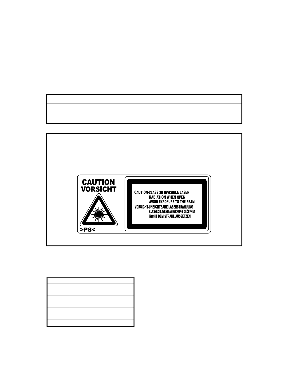
WARNING FOR LASER UNIT
WARNING: Turn off the main switch before attempting any of the
procedures in the Laser Unit section. Laser beams can cause
serious damage to eyes.
CAUTION MARKING:
B130R934.WMF
Symbols and Abbreviations
This manual uses the symbols and abbreviations shown below.
Symbol Meaning
"See," "Refer to"
Clip ring
Screw
Connector
SEF Short Edge Feed
LEF Long Edge Feed
Core Technology manual
CÓPIA NÃO CONTROLADA
CÓPIA NÃO CONTROLADA
Page 25
INSTALLATION
B696 DOCUMENT FEEDER (B129/B130/B168/B169)
B444 DOCUMENT FEEDER (B044/B045/B046)
FAX UNIT (B130/B168/B169)
IFAX (B130 ONLY)
PREVENTIVE MAINTENANCE
B421 PAPER TRAY UNIT (ALL MODELS)
REPLACEMENT AND ADJUSTMENT
B465 FAX UNIT (B044/B045/B046)
TROUBLESHOOTING
B683 PRINTER/SCANNER UNIT (B129/B130)
B441 PRINTER CONTROLLER (B044/B045/B046)
SERVICE TABLES
DETAILED DESCRIPTIONS
SPECIFICATIONS
TAB
POSITION 2
TAB
POSITION 1
TAB
POSITION 3
TAB
POSITION 4
TAB
POSITION 6
TAB
POSITION 5
TAB
POSITION 8
TAB
POSITION 7
CÓPIA NÃO CONTROLADA
CÓPIA NÃO CONTROLADA
Page 26

CÓPIA NÃO CONTROLADA
CÓPIA NÃO CONTROLADA
Page 27

INSTALLATION
CÓPIA NÃO CONTROLADA
CÓPIA NÃO CONTROLADA
Page 28

CÓPIA NÃO CONTROLADA
CÓPIA NÃO CONTROLADA
Page 29
INSTALLATION REQUIREMENTS
SM 1-1 B129 Series/B044 Series
Installation
1. INSTALLATION
CAUTION
Before installing an optional unit, do the following:
1. If there is a fax unit on the machine, print out all messages stored in the
memory, all user-programmed items, and a system parameter list.
2. If there is a printer option on the machine, print out all data in the
printer buffer.
3. Turn off the main switch and disconnect the power cord, the telephone
line, and the network cable.
1.1 INSTALLATION REQUIREMENTS
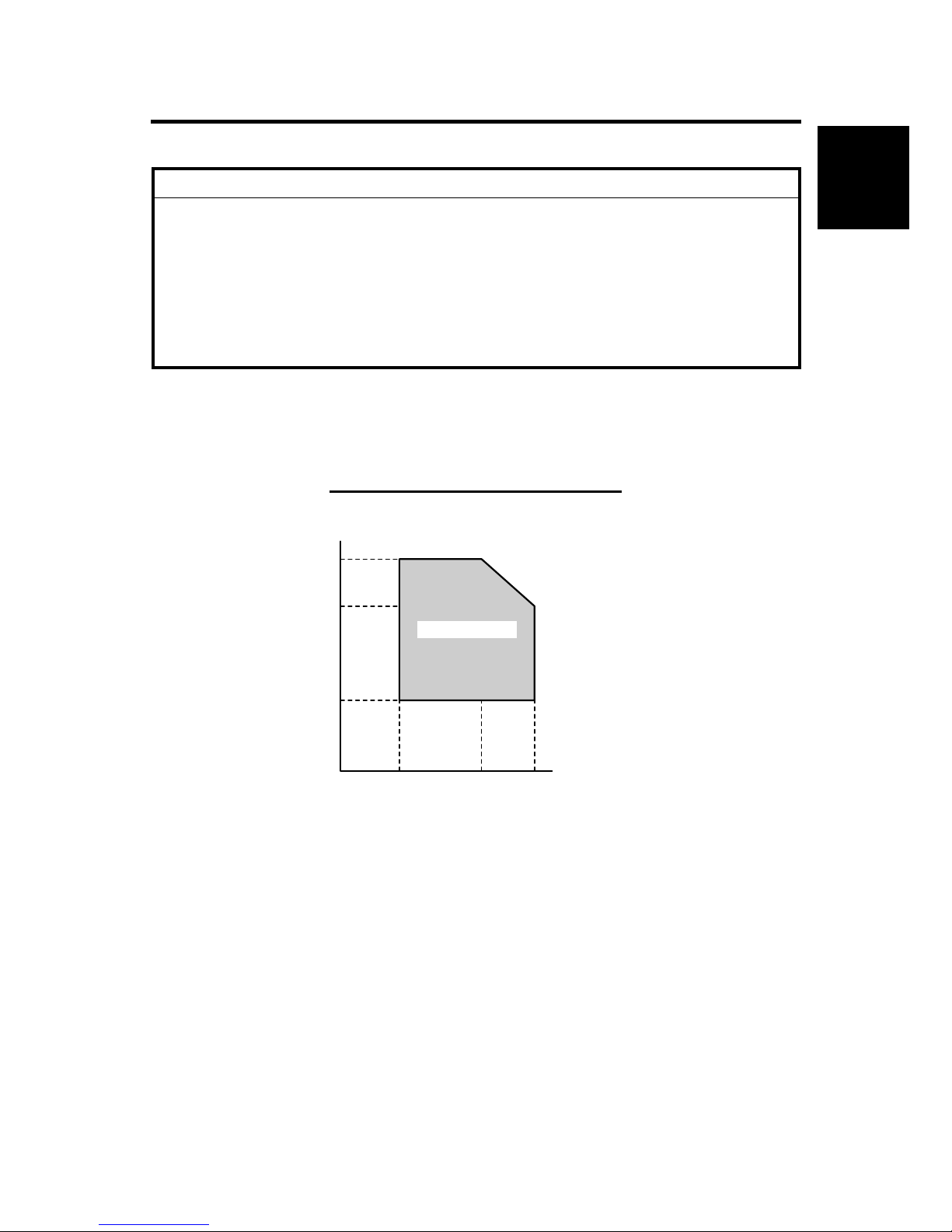
1.1.1 ENVIRONMENT
–Temperature and Humidity Chart–
1. Temperature Range: 10°C to 32°C (50°F to 89.6°F)
2. Humidity Range: 15% to 80% RH
3. Ambient Illumination: Less than 1,500 lux (Do not expose to direct sunlight.)
4. Ventilation: Room air should turn over at least 3 times/hr/person
5. Ambient Dust Less than 0.1 mg/m3
6. Do not install the machine where it will be exposed to direct sunlight or to direct
airflow (from a fan, air conditioner, air cleaner, etc.).
7. Do not install the machine where it will be exposed to corrosive gas.
8. Place the machine on a firm and level base.
9. Do not install the machine where it may be subjected to strong vibration.
Humidity
10°C
(50°F)
27°C
(80.6°F)
32°C
(89.6°F)
15%
54%
80%
Temperature
Operation range
B046I512.WMF
CÓPIA NÃO CONTROLADA
CÓPIA NÃO CONTROLADA
Page 30
INSTALLATION REQUIREMENTS
B129 Series/B044 Series 1-2 SM
1.1.2 MACHINE LEVEL
Front to back: Within 5 mm (0.2") of level
Right to left: Within 5 mm (0.2") of level
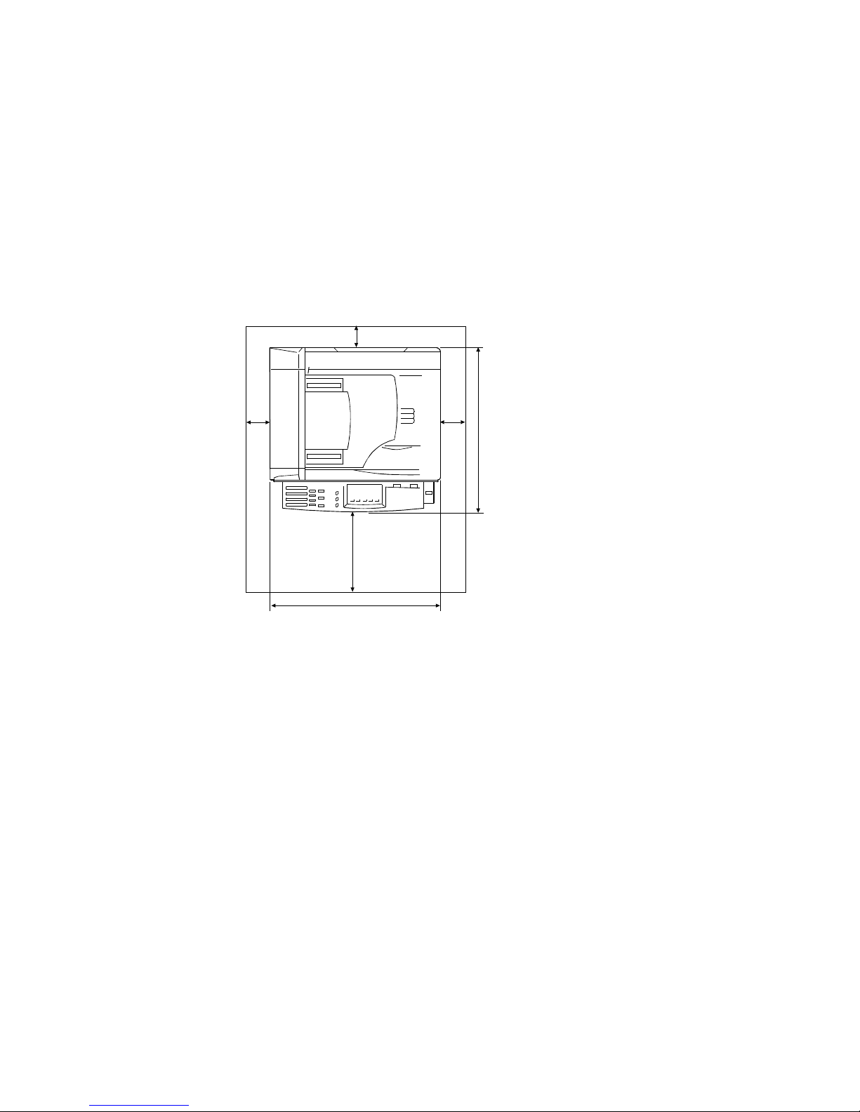
1.1.3 MINIMUM OPERATIONAL SPACE REQUIREMENTS
Place the machine near the power source, providing clearance as shown.
NOTE:
1) The 750-mm front space indicated above is sufficient to allow the paper
tray to be pulled out. Additional space is required to allow an
operator to stand at the front of the machine.
2) Actual minimum space requirement for left, rear, and right sides is
10mm (0.4") each, but note that this will not allow room for opening of
the bypass tray, right door, platen cover, or ADF unit.
B046I130.WMF
A: Front – 750 mm (29.6")
B: Left – 100 mm (3.9")
C: Rear – 105 mm (4.1")
D: Right – 230 mm (9.0")
[C]
[D]
[B]
[A]
450 mm (17.7")
468 mm (18.4")
CÓPIA NÃO CONTROLADA
CÓPIA NÃO CONTROLADA
Page 31

INSTALLATION REQUIREMENTS
SM 1-3 B129 Series/B044 Series
Installation
1.1.4 POWER REQUIREMENTS
CAUTION
1. Make sure that the wall outlet is near the machine and easily accessible.
After completing installation, make sure the plug fits firmly into the
outlet.
2. Avoid multi-wiring.
3. Be sure to ground the machine.
Input voltage:
North America: 110 – 120 V, 60 Hz, 8 A
Europe: 220 – 240 V, 50/60 Hz, 4 A
Image quality guaranteed at rated voltage ± 10%.
Operation guaranteed at rated voltage ± 15%.
CÓPIA NÃO CONTROLADA
CÓPIA NÃO CONTROLADA
Page 32

COPIER
B129 Series/B044 Series 1-4 SM
1.2 COPIER
1.2.1 ACCESSORY CHECK
Basic Model (B129)
No. Description Q’ty
1 General Settings Guide (-17, -21, -29) 1
2 Copy Reference (-17, -21, -29) 1
3 EU Safety Sheet (-22, -24, -26, -27) 1
4 NECR (-17, -21, -27, -29) 1
5 Paper Size Decal 1
6 Brand Decal (-22, -29) 1
MFP Model (B130)
No. Description Q’ty
1 General Settings Guide (-17, -21, -29) 1
2 Copy Reference (-17, -21, -29) 1
3 Facsimile Reference <Basic Features> (-17, -21, -29) 1
4 Facsimile Reference <Advanced Features> (-17, -21, -29) 1
5 Printer Setup Guide (-17, -21, -29) 1
6 CD-ROM (Printer Reference/Scanner Reference) (-17, -21, -29) 1
7 CD-ROM (Driver: Printer/Scanner) (-21, -22, -24, -26, -27, -29) 1
8 CD-ROM (Driver: Utility) 1
9 EU Safety Sheet (-22, -24, -26, -27) 1
10 NECR (-17, -21, -27, -29) 1
11 Paper Size Decal 1
12 Modular Cable (-17) 1
13 Handset Bracket (-17) 1
14 Facsimile Panel Decal (-17, -21, -29) 1
15 Ferrite Core 1
16 Brand decals (-22, -29) 1
NOTE: Retain the handset bracket. The optional handset kit does not include the
bracket.
CÓPIA NÃO CONTROLADA
CÓPIA NÃO CONTROLADA
Page 33

COPIER
SM 1-5 B129 Series/B044 Series
Installation
Copier/Facsimile Model (B168)
No. Description Q’ty
1 General Settings Guide (-17, -21, -29) 1
2 Copy Reference (-17, -21, -29) 1
3 Facsimile Reference <Basic Features> (-17, -21, -29) 1
4 Facsimile Reference <Advanced Features> (-17, -21, -29) 1
5 EU Safety Sheet (-22, -24, -26, -27) 1
6 NECR (-17, -21, -27, -29) 1
7 Paper Size Decal 1
8 Modular Cable (-17) 1
9 Handset Bracket (-17) 1
10 Facsimile Panel Decal (-17, -21, -29) 1
11 Brand decals (-22) 1
NOTE: Retain the handset bracket. The optional handset kit does not include the
bracket.
Copier/Printer/Scanner Model (B169) (not sold in U.S. market)
No. Description Q’ty
1 CD-ROM (Driver: Printer/Scanner) (-22, -24, -26) 1
2 CD-ROM (Driver: Utility) 1
3 EU Safety Sheet 1
4 NECR (-27) 1
5 Paper Size Decal 1
6 Ferrite Core 1
7 Brand decals (-22) 1
NOTE: For B044/B045 models, use B129 “Basic Model” Accessory Check. For
B046, use B168 “Copier/Facsimile” Accessory Check.
CÓPIA NÃO CONTROLADA
CÓPIA NÃO CONTROLADA
Page 34

COPIER
B129 Series/B044 Series 1-6 SM
1.2.2 INSTALLATION PROCEDURE
CAUTION
Make sure that the copier remains unplugged during installation.
1. Remove the strips of tape.
2. Remove the bags [A][B][C] holding the
included accessories.
NOTE: Accessories vary according to
models.
3. Remove the spacing wedge [D].
4. Remove the System Parameter
Report [E] and keep it in a safe
place.
NOTE: You need this report for
adjustment or
troubleshooting.
B130I901.WMF
B130I902.WMF
[C]
[A]
[B]
[D]
[E]
CÓPIA NÃO CONTROLADA
CÓPIA NÃO CONTROLADA
Page 35

COPIER
SM 1-7 B129 Series/B044 Series
Installation
5. Remove the three scanner lock
pins. (A tag is hanging from each
pin.) To remove: Grasp the base
of the pin [A], turn the pin 90
degrees, and pull it down and out.
6. Remove the tags from the pins.
7. Break each pin off the base [A].
8. Discard the pin part [B].
9. Set each base [A] back into its original hole, turning it 90° to lock it into place.
(Be sure to do this for all three pins.)
10. When installing a DF-equipped
model
(B046/B129/B130/B168/B169),
raise the DF upper guide [C] and
remove the protective paper [D] at
the feed unit. Then lower the guide.
11. Open the platen cover [E] (or DF, if
equipped) and remove the
protective paper [F] covering the
exposure glass. Then close the
platen cover/DF.
B046I106.WMF
B046I107.WMF
[E]
[F]
[C]
[D]
[A]
[B]
CÓPIA NÃO CONTROLADA
CÓPIA NÃO CONTROLADA
Page 36

COPIER
B129 Series/B044 Series 1-8 SM
12. Open the front door [A].
NOTE: For B045 model only,
skip to step 18a.
13. Lift lever [B], press in on latch [C]
and pull the bottle holder [D] out.
(You do not need to pull it
completely out of the machine.)
14. Take a new bottle of toner, and
shake it several times.
15. Remove the outer cap [E].
NOTE: DO NOT remove the inner
cap [F].
16. Load the bottle on the holder.
NOTE: DO NOT forcefully turn the
toner bottle on the holder.
After you turn on the main
power switch, the copier sets
the bottle in place.
17. Push the bottle holder back into the
machine.
18. Press the latch [G] down to lock the
holder.
18a. (B045 Model only)
If installing a toner-hopper
magazine (THM) model:
Shake the magazine several
times, then peel off the paper [H]
from a new THM [I], and load the
THM into the machine.
B046I112.WMF
B046I301.WMF
B046I114.WMF
[C]
[B]
[D]
[A]
[I]
[H]
[E]
[F]
[G]
CÓPIA NÃO CONTROLADA
CÓPIA NÃO CONTROLADA
Page 37

COPIER
SM 1-9 B129 Series/B044 Series
Installation
19. Remove the padding [A].
20. Pull the tabbed strips [B] out
of the PCU.
21. Close the front door.
22. Pull out the paper tray, and
remove the tape [C] securing
the end fence in the
compartment.
23. Push the bottom plate [D] down.
24. Load the paper.
25. Adjust the side fences. If you load the paper shorter than A4, set the end fence
[E] in position.
B130I903.WMF
B046I119.WMF
[C]
[D]
[E]
[A]
[B]
CÓPIA NÃO CONTROLADA
CÓPIA NÃO CONTROLADA
Page 38

COPIER
B129 Series/B044 Series 1-10 SM
26. Push the tray back in the copier.
27. Attach the appropriate Brand
Decal to the center of the front
door [A] if necessary.
28. Attach the appropriate tray
number decal and paper-size
decal to the paper tray [B].
29. Install optional units (if any).
NOTE: Optional unit installation
procedures can be found
via the Table of
Contents/Section 1 of this
Service Manual.
30. Attach the ferrite core to the
network cable when connecting
the cable.
31. Connect a telephone line as
necessary (per model
configuration).
32. Plug in the machine and turn on
the main power switch.
B046I515.WMF
B130I909.WMF
[A]
[B]
[C]
CÓPIA NÃO CONTROLADA
CÓPIA NÃO CONTROLADA
Page 39

COPIER
SM 1-11 B129 Series/B044 Series
Installation
33. Select the language used in the operation panel as necessary ( >
Language).
34. Make a full size copy, and check if the side-to-side and leading edge
registrations are correct. If they are not, adjust the registrations.
NOTE 1: The following steps 35 to 44 are for the B130/B168/B169 ONLY:
NOTE 2: For B044/B045/B046 go to step 46:
35. Activate the SP mode ( 5.1.1)
36. Select Copy SP 5-302-002 (Time) and specify the time difference.
37. Quit the SP mode.
38. Activate the User Tools ().
39. Specify the date and time (System Settings > Timer Settings > Set Date/Set
Time).
40. Quit the User Tools.
41. Activate the SP mode.
42. Select Copy SP5-307.
43. Specify the daylight-saving-time settings.
44. B129/B130/B168/B169 Only: Exit the SP Mode now.
45. B044/B045/B046 Only: Enter SP mode (See 5.1 Accessing SP Mode), and run
SP7-825 to initialize the electrical total counter to 0.
NOTE:
1) After selecting SP7-825, enter "1" and then hold down the Original
Type key and press the OK key to initialize the counter. If
initialization is successful, the screen displays "Action completed."
2) SP7-825 is effective only once, at time of machine installation.
Rev. 11/2004
CÓPIA NÃO CONTROLADA
CÓPIA NÃO CONTROLADA
Page 40

COPIER
B129 Series/B044 Series 1-12 SM
46. B046 only: Access SP5-992 and select "2" to print out a full SMC report.
Confirm that the report shows a "YES" for SP7-801-3.
47. B046 only: After connecting the telephone line to the appropriate telephone
wall jack and LINE press the On Hook key on the fax operation panel, and
confirm that you hear a dial tone coming from the monitor speaker.
48. Program the required items, as indicated below.
49. Exit the SP Mode now.
Initial Programming: Faxless models (B044, B045)
Items to Program (Service Level – SP Mode)*1
SP No.
Date and time 5-302
Language replacement (Firmware download) 5-827
*1: See Section 5 for SP-mode usage instructions.
Items to Program (User Level)
*2
User Tools
Display contrast
Energy saver level (low power mode)
Reception mode
User Tools →
System Settings
Other items, as necessary *2
*2: Refer to the Operating Instructions for details.
Initial Programming: Fax-equipped model (B046)
Items to Program (Service Level – Service Functions
)
*3
Function No.
Country code (System switch 0F) 01
Protocol requirements (G3 switch 0B) - EU only 01
PM call (System switch 01 – bit 0) 01
Country code (NCU parameter 00) 07
Service station's fax number 09
*3: See Section 5.1.1 of the fax service manual for information about using
service functions.
Items to Program (Service Level – SP Mode) *4
SP No.
Machine's serial number 5-811
Language replacement (Firmware download) 5-827
PSTN access code (RAM address 4000DB)
PSTN access method (RAM address 4000CD)
Periodic service call (RAM addresses 40054F to 400553)
7-955
*4: See Section 5 for SP-mode usage instructions.
Rev.11/2004
CÓPIA NÃO CONTROLADA
CÓPIA NÃO CONTROLADA
Page 41

PAPER TRAY UNIT
SM 1-13 B129 Series/B044 Series
Installation
Items to Program (User Administrator Level) *5
User Tools
Monitor volume
Display contrast
Date and Time
Reception mode
Fax Header/Own Name/Own No. (TTI/RTI/CSI)
Fax Features
→ Setup
Reports on/off
Country Code (except NA)
Key Op. Tools
Fusing power control during energy saver mode
System
Settings
Language selection Language
Other initial programming items *5
*5: Refer to the Operating Instructions for details.
1.3 PAPER TRAY UNIT
1.3.1 ACCESSORY CHECK
Confirm that you have the accessories indicated below.
No. Description Q’ty
1 Paper-size decals 1 sheet
2 Installation Procedure (for service person) 1
3 Installation Procedure (for user) 1
Rev.11/2004
CÓPIA NÃO CONTROLADA
CÓPIA NÃO CONTROLADA
Page 42

PAPER TRAY UNIT
B129 Series/B044 Series 1-14 SM
1.3.2 INSTALLATION PROCEDURE
CAUTION
Unplug the main machine's power cord before starting the following
procedure.
1. Remove the tape at [A], and the tape and cardboard at [B].
2. Pull the paper tray part way out of the
unit, remove the tape and cardboard
at [C], and push the tray back in.
B046I516.WMF
[A]
[B]
[C]
CÓPIA NÃO CONTROLADA
CÓPIA NÃO CONTROLADA
Page 43

PAPER TRAY UNIT
SM 1-15 B129 Series/B044 Series
Installation
3. Set the machine onto the paper tray unit.
4. Remove the paper tray from the paper tray unit.
5. Load paper into the paper tray. Adjust the side and end fences as necessary. If
loading 81/2"x 14" paper, remove the end fence and set it into the special
compartment.
6. Set the paper tray back into the paper tray unit.
7. Attach the appropriate tray-number decal
and paper-size decal, at the locations
indicated in the illustration.
B046I527.WMF
B046I517.WMF
CÓPIA NÃO CONTROLADA
CÓPIA NÃO CONTROLADA
Page 44

PAPER TRAY UNIT HEATER
B129 Series/B044 Series 1-16 SM
1.4 PAPER TRAY UNIT HEATER
1.4.1 ACCESSORY CHECK
Confirm that you have the accessories indicated below.
No. Description Q’ty
1 Grounding wire 1
2 Relay harness 1
3 Clamps 2
4 Ferrite core 1
5 Heater fastening screws 2
6 PTU fastening screws 3
7 Grounding screw 1
8 Decal for copier 1
9 Decal for paper unit 1
10 Tie wrap 1
B046I518.WMF
1
5
9
3
2
4
7
8
10
6
CÓPIA NÃO CONTROLADA
CÓPIA NÃO CONTROLADA
Page 45

PAPER TRAY UNIT HEATER
SM 1-17 B129 Series/B044 Series
Installation
1.4.2 INSTALLATION PROCEDURE
CAUTION
Unplug the main machine's power cord before starting the following
procedure.
1. Remove the paper tray unit from the copier if it is already installed.
2. Remove the paper trays from the copier and from the paper tray unit.
3. Remove the ground screw [A] at the
rear of the paper tray unit.
4. Fasten the heater [B] and the supplied
ground wire [C] to the paper tray unit
( x 3). Note that [A] is the ground
screw you removed in the previous
step and [D] and [E] are the two
supplied heater fastening screws.
NOTE: Be sure to position the ground
wire [C] and heater harness
[F] so that they are out of the
way of the copier when you
set it onto the paper tray unit.
5. Set the copier onto the paper tray unit.
6. Screw the paper tray unit into place
using three supplied PTU fastening
screws.
B046I519.WMF
B046I500.WMF
[B]
[C]
[A]
[D]
[E]
[F]
CÓPIA NÃO CONTROLADA
CÓPIA NÃO CONTROLADA
Page 46

PAPER TRAY UNIT HEATER
B129 Series/B044 Series 1-18 SM
7. Open the front door [A].
8. Remove the copy tray [B] (×1).
9. Close the front door.
10. (B129/B130/B168/B169 Only) Remove
the memory card cover [C] ( x 1).
11. Remove the rear cover [D] ( x 5).
12. (B044/B045/B046 Only) Remove the FCU cover plate [D] (7 screws on faxless
machines, 8 screws on fax-equipped machines).
NOTE: On fax-equipped machines, detach the NCU connector [E] first.
Faxless machines: Fax-equipped machines:
B046I501.WMF
B130R901.WMF
B046I504.WMF
B046I503.WMF
[B]
[A]
[C]
[D]
[E]
[D]
CÓPIA NÃO CONTROLADA
CÓPIA NÃO CONTROLADA
Page 47

PAPER TRAY UNIT HEATER
SM 1-19 B129 Series/B044 Series
Installation
13. (B129/B130/B168/B169) Remove the upper left cover [E]. Remove the BICU
cover [F] ( x 3) or the controller box [G] ( x 1, x 5).
14. (B129/B130/B168/B169) Remove the
support bracket [A]
( x 2).
B130R933.WMF
B130R921.WMF
B130I905.WMF
[A]
[F]
[E]
[G]
[E]
CÓPIA NÃO CONTROLADA
CÓPIA NÃO CONTROLADA
Page 48

PAPER TRAY UNIT HEATER
B129 Series/B044 Series 1-20 SM
15. Pass the heater harness through the
hole [B] at the rear of the copier.
16. Pass relay harness [C] through the
opening [D] (at the rear of the PSU)
and through the other opening [B].
17. Connect the relay harness to the
heater's harness [E].
18. Pull the relay harness back into
the copier.
19. Attach the ferrite core [A] over the
relay harness.
20. Push the ferrite core back so that
it is over the heater's harness.
21. Wrap the heater's harness once
around the ferrite core [B].
22. Locate the ferrite core at the rear of
the copier [A] behind the rear clamp.
23. Secure the ferrite core with the
supplied tie wrap [C].
24. Clip off the excess length of the tie wrap [D].
25. Connect the relay harness connector [E] to the large connector at the front
center of the PSU.
26. Screw the ground wire [F] to the PSU bracket with the included grounding
screw.
27. Attach the clamps [G] to the PSU bracket.
28. Attach the heater harness though the clamps.
29. Position the harness so that the front clamp is between the two bindings [H] on
the harness.
30. Fasten the clamps.
B046I520.WMF
B046I521.WMF
[A]
[B]
[C]
[D]
[E]
[F]
[H]
[G]
[B]
[C]
[D]
[E]
CÓPIA NÃO CONTROLADA
CÓPIA NÃO CONTROLADA
Page 49

PAPER TRAY UNIT HEATER
SM 1-21 B129 Series/B044 Series
Installation
31. Pull the excess length of the heater's
harness out the opening at the rear
[A].
NOTE: Be sure that the harness
passes on the side of the
grounding plate [B] at the
bottom of the opening. (The
front of the grounding plate
must remain clear.)
32. Arrange the excess harness length so
that it sits beneath the FCU cover
plate.
33. Attach the caution decals to the
locations shown in the illustration.
34. Reassemble the copier.
35. Plug in the power cord, and verify
component operation.
B046I522.WMF
B046I523.WMF
[A]
[B]
CÓPIA NÃO CONTROLADA
CÓPIA NÃO CONTROLADA
Page 50

DOCUMENT FEEDER (B696 AND B444)
B129 Series/B044 Series 1-22 SM
1.5 DOCUMENT FEEDER (B696 AND B444)
1.5.1 ACCESSORY CHECK
No. Description Q’ty
1 ADF connection board 1
2 Cable 1
3 ADF body 1
4 Screw M3 x 6 2
5 Hex screw 4
6 Hex wrench 1
7 ADF original table 1
8 Installation procedure 1
B696I908.WMF
7
4
1
2
3
5
6
Rev. 11/2004
CÓPIA NÃO CONTROLADA
CÓPIA NÃO CONTROLADA
Page 51

DOCUMENT FEEDER (B696 AND B444)
SM 1-23 B129 Series/B044 Series
Installation
1.5.2 INSTALLATION PROCEDURE
CAUTION
Unplug the main machine's power cord before starting the following
procedure.
1. Unpack the ADF and remove the packing tape from the bottom of the ADF
body.
2. Lift the platen cover [A], unlatch
the two latches [B] (press down on
the tabs [C]), and detach the cover
from the hook [D].
3. Push the left piece [E] to the left
and pull it up and off.
B046I505.WMF
B046I525.WMF
[A]
[B]
[C]
[D]
[E]
CÓPIA NÃO CONTROLADA
CÓPIA NÃO CONTROLADA
Page 52

DOCUMENT FEEDER (B696 AND B444)
B129 Series/B044 Series 1-24 SM
4. Place the ADF original table [A]
on the platen cover.
5. Insert the three latches into the
openings.
NOTE: The latches may break
if you try to push the
table in at an angle.
6. Make sure that that the contact
area [B] around each latch is
flush against the cover.
7. (B129/B130/B168/B169 Only) Remove
the memory card cover [C] ( x 1)
8. Remove the rear cover [D] ( x 5).
B696I909.WMF
B696I902.WMF
[A]
[B]
[D]
[C]
CÓPIA NÃO CONTROLADA
CÓPIA NÃO CONTROLADA
Page 53

DOCUMENT FEEDER (B696 AND B444)
SM 1-25 B129 Series/B044 Series
Installation
9. Remove the left scale plate [A]
( x 2).
10. Remove the upper left cover [B].
11. Set the ADF body [C] onto the
copier.
12. Press the latch [D] to raise the
top half of the body.
13. Fasten the ADF body with the
hex screws ( x 4).
NOTE: Use the hex wrench.
B696I904.WMF
B696I903.WMF
[A]
[D]
[C]
[B]
CÓPIA NÃO CONTROLADA
CÓPIA NÃO CONTROLADA
Page 54

DOCUMENT FEEDER (B696 AND B444)
B129 Series/B044 Series 1-26 SM
For the B129/B130/B168/B169 Models: Use steps 14-21, Then proceed to
step 25.
14. Remove the ADF connection board guard [A] (if installed) ( x 2).
15. Insert the top of the ADF connection board [B] into the bracket [C].
16. Fasten the screw [D].
NOTE: Fasten this screw before fastening the other screw [E].
17. Fasten the screw [E].
18. Connect the cables on the ADF connection board:
• CN303
• CN306
• CN305
• CN307
19. Fix the cables with the clamp [F].
20. Connect the cables [G] between the ADF connection board and the BICU:
• ADF connection board CN302 ↔ BICU CN109
• ADF connection board CN301 ↔ BICU CN110
21. Fasten the cables with the clamp [H].
B696I905.WMF
[A]
[B]
[G]
[H]
[C]
[D]
[E]
[F]
CÓPIA NÃO CONTROLADA
CÓPIA NÃO CONTROLADA
Page 55

DOCUMENT FEEDER (B696 AND B444)
SM 1-27 B129 Series/B044 Series
Installation
For the B044/B045/B046 Models: Use steps 22-24. Then proceed to step 25.
22. Install the DF connection board [A] and DF board bracket [B]. ( x 5)
23. Connect the four wire sets from the DF body to CN103, CN105, CN106, and
CN107 on the DF connection board. (Not shown in illustration.)
24. Connect one end of the supplied wire harness [C] to CN101 and CN102 on the
DF connection board, and connect the other end to connectors CN9 and CN10
on the FCU. Secure the wire harness into the clamp [D] located to the side of
the DF board.
25. Reassemble the whole copier.
26. Plug in the power cord, and turn on the main switch.
27. Make a full-size copy from the paper tray using the ADF, and check the leading
edge registration. Adjust the registration as necessary. (Registration
adjustment procedures are located in Section 3 “Replacement and Adjustment”
of this Service Manual.)
B046I513.WMF
[A]
[B]
[C]
[D]
CÓPIA NÃO CONTROLADA
CÓPIA NÃO CONTROLADA
Page 56

PRINTER SCANNER UNIT B683
B129 Series/B044 Series 1-28 SM
1.6 PRINTER SCANNER UNIT B683
NOTE: For the Installation of the B441 Printer Controller Type 1013 for the
B044/B045/B046 refer to the B441 manual.
1.6.1 ACCESSORY CHECK
No. Description Q’ty
1 ADF Connection Board Guard 1
2 Screw M3 x 6 9
3 Controller Box 1
4 Printer Panel 1
5 Printer Key 2
6 Copier Key 2
7 Scanner Key 2
8 Multi-function Panel 1
9 Operation Instruction (Book) 1
10 CD-ROM 1 set
11 FCC Decal (-15) 1
12 Ferrite Core 1
13 Ground Plate 1
14 Installation Procedure 1
B683I908.WMF
5
10
3
8
1
2
4
67
9
11
12
13
Rev. 11/2004
CÓPIA NÃO CONTROLADA
CÓPIA NÃO CONTROLADA
Page 57

PRINTER SCANNER UNIT B683
SM 1-29 B129 Series/B044 Series
Installation
1.6.2 INSTALLATION PROCEDURE
CAUTION
Unplug the main machine's power cord before starting the following
procedure.
1. Remove the memory card
cover [A] ( x 1).
2. Remove the rear cover [B]
( x 5).
3. Cut the opening [C] on the rear
cover. This opening is for the
network interfaces.
4. Cut another opening [D] on the
rear cover. This opening is for
the SD card slot and the LAN
cable.
NOTE: DO NOT cut the
topmost opening [E]
when the machine is
the basic model (B129).
5. Remove the upper left cover [F].
B696I902.WMF
B696I907.WMF
[B]
[F]
[A]
[C]
[D]
[E]
CÓPIA NÃO CONTROLADA
CÓPIA NÃO CONTROLADA
Page 58

PRINTER SCANNER UNIT B683
B129 Series/B044 Series 1-30 SM
6. Install the ground plate [A] ( x 2).
NOTE: Insert the upper and lower hooks in the openings [B], and fasten the
upper screw first.
7. Attach connection board guard [C].
NOTE: The North America model (B129) has the ADF connection board [D].
8. Fasten the side screw [E].
9. Fasten the rear screw [F].
10. Install the controller box [G] ( x 5, x 1).
NOTE: Insert the bracket [H] into the frame. The connector on the controller
box engages with the connector on the BICU.
11. Install PostScript 3 as necessary.
B683I913.WMF
B683I902.WMF
[E]
[A]
[B]
[G]
[H]
[F]
[C]
[D]
CÓPIA NÃO CONTROLADA
CÓPIA NÃO CONTROLADA
Page 59

PRINTER SCANNER UNIT B683
SM 1-31 B129 Series/B044 Series
Installation
12. Remove the front left cover [A] ( x 2).
NOTE: Retain the screws and use them in the next step.
13. Install the multi-function panel [B] ( x 1, x 2).
B683I510.WMF
B683I903.WMF
[A]
[B]
CÓPIA NÃO CONTROLADA
CÓPIA NÃO CONTROLADA
Page 60

PRINTER SCANNER UNIT B683
B129 Series/B044 Series 1-32 SM
14. Remove the panel cover [A].
15. Remove the filament tape from the printer panel [B].
16. Install the printer panel.
17. Install one of the printer keys [C].
18. Remove the key cover [D].
19. Install one of the copier keys [E].
20. Install one of the scanner keys [F].
B683I109.WMF
B683I916.WMF
[C]
[D]
[F]
[A]
[B]
[E]
CÓPIA NÃO CONTROLADA
CÓPIA NÃO CONTROLADA
Page 61

PRINTER SCANNER UNIT B683
SM 1-33 B129 Series/B044 Series
Installation
21. For North America model only:
Attach the FCC decal [A] to the rear side
of the copier.
22. Reassemble the whole copier.
23. Attach the ferrite core [B] to the
network cable and attach the cable to
the copier if a network cable is used.
The end of the ferrite core must be
about 15 cm (6") from the end of the
cable [C].
24. Plug in the power cord, and turn on
the main switch.
25. Verify unit operation.
B683I917.WMF
B441I108.WMF
B622I903.WMF
[A]
[B]
[C]
CÓPIA NÃO CONTROLADA
CÓPIA NÃO CONTROLADA
Page 62

POSTSCRIPT 3
B129 Series/B044 Series 1-34 SM
1.7 POSTSCRIPT 3
1. Remove the memory card cover [A]
( x 1).
2. Remove the rear cover [B] ( x 5).
3. Remove the upper left cover [C] if
the fax control unit is installed.
4. Remove the controller box cover
[D]
( x 12).
5. Remove the fax control unit (if
installed) [E] ( x 1, x 3).
6. Install the PostScript 3 emulation board [F].
7. Reassemble the copier.
8. Plug in the power cord, and turn on the main
switch.
9. Verify unit operation.
B696I902.WMF
B683I904.WMF
B683I905.WMF
[B]
[C]
[F]
[D]
[E]
[A]
CÓPIA NÃO CONTROLADA
CÓPIA NÃO CONTROLADA
Page 63

IEEE 1284/IEEE 1394/BLUETOOTH INTERFACE
SM 1-35 B129 Series/B044 Series
Installation
1.8 IEEE 1284/IEEE 1394/BLUETOOTH INTERFACE
CAUTION
Unplug the machine power cord before starting the following procedure.
NOTE:
1) To install an optional network interface, the Printer/Scanner Option is
required.
2) One slot is available. You can install only one of the following: IEEE
1284 interface, IEEE 1394 interface, wireless LAN interface, or
Bluetooth interface.
1. Remove the slot cover [A] ( x 2).
2. Install the interface board [B]
( x 2).
B683I909.WMF
[B]
[A]
CÓPIA NÃO CONTROLADA
CÓPIA NÃO CONTROLADA
Page 64

WIRELESS LAN
B129 Series/B044 Series 1-36 SM
1.9 WIRELESS LAN
1.9.1 ACCESSORY CHECK
Check the quantity and condition of the accessories.
No. Description Q’ty
1 Wireless LAN card 1
2 Wireless LAN card cover 1
3 Wireless LAN board 1
1.9.2 INSTALLATION PROCEDURE
CAUTION
Unplug the machine power cord before starting the following procedure.
NOTE:
1) To install an optional network interface, the Printer/Scanner Option is
required.
2) One slot is available. You can install only one of the following: IEEE
1284 interface, IEEE 1394 interface, wireless LAN interface, or
Bluetooth interface.
1. Remove the slot cover [A] ( x 2).
2. Turn the card face [B] to the front side of the copier, and insert it into the
wireless LAN (IEEE 802.11b) board [C].
3. Install the wireless LAN board (with the card) to the slot ( x 2).
4. Attach the cover [D].
5. If reception is poor, you may need to move the machine:
• Ensure that the machine is not located near an appliance or any type of
equipment that can generate a strong magnetic field.
• Position the machine as close as possible to the access point.
B683I919.WMF
[A]
[C]
[B]
[D]
CÓPIA NÃO CONTROLADA
CÓPIA NÃO CONTROLADA
Page 65

WIRELESS LAN
SM 1-37 B129 Series/B044 Series
Installation
UP Mode Settings for Wireless LAN
Enter the UP mode and follow the procedure below to perform the initial interface
settings for IEEE 802.11b. These settings take effect every time the machine is
powered on.
NOTE: The wireless LAN cannot be used if Ethernet is being used.
1. Press the User Tools/Counter key.
2. On the touch panel, press System Settings.
NOTE: The Network I/F (default: Ethernet) must be set for either Ethernet or
wireless LAN.
3. Select Interface Settings → Network (tab) → LAN Type
4. Select either “Ethernet” or “IEEE 802.11b”.
5. Press IEEE 802.11b. Only the wireless LAN options are displayed.
6. Transmission Mode. Select either “Ad Hoc Mode” or “Infrastructure Mode”.
7. SSID Setting. Enter the SSID setting. (The setting is case sensitive.)
8. Channel. This setting is required when Ad Hoc Mode is selected.
Range: 1 ~ 14 (default: 11)
NOTE: The allowed range for the channel settings may vary for different
countries.
9. WEP (Privacy) Setting. The WEP (Wired Equivalent Privacy) setting is
designed to protect wireless data transmission. In order to unlock encoded
data, the same WEP key is required on the receiving side. There are 64 bit and
128 bit WEP keys.
Range of Allowed Settings:
64 bit 10 characters
128 bit 26 characters
10. Bandwidth Status. This setting is enabled only for the Infrastructure Mode.
Press here to display the current status of the bandwidth. One of the following
is displayed to reflect the reception status of the wireless LAN:
Good 76 ~ 100%
Fair 41 ~ 75%
Poor 21 ~ 40%
Unavailable 0 ~ 20%
CÓPIA NÃO CONTROLADA
CÓPIA NÃO CONTROLADA
Page 66

WIRELESS LAN
B129 Series/B044 Series 1-38 SM
11. Transmission Speed. Press the Next button to display more settings, then
select the transmission speed for the mode: Auto, 11 Mbps, 5.5 Mbps, 2 Mbps,
1 Mbps (default: Auto). This setting should match the distance between the
closest machine or access point, depending upon which mode is selected.
NOTE: For the Ad Hoc Mode, this is the distance between the machine and
the closest PC in the network. For the Infrastructure Mode, this is the
distance between the machine and the closest access point.
11 Mbps 140 m (153 yd.)
5.5 Mbps 200 m (219 yd.)
2 Mbps 270 m (295 yd.)
1 Mbps 400 m (437 yd.)
12. To initialize the wireless LAN settings, use page 2/2 on the display panel. Press
Execute to initialize the following settings:
• Transmission mode
• Channel
• Transmission Speed
• WEP
• SSID
• WEP Key
SP Mode Settings for IEEE 802.11b Wireless LAN
The following SP commands can be set for IEEE 802.11b
SP No. Name Function
5840 004 SSID Used to confirm the current SSID setting.
5840 006 Channel MAX Sets the maximum range of the channel settings for the
country.
5840 007 Channel MIN Sets the minimum range of the channels settings allowed
for your country.
5840 011 WEP Key Select Used to select the WEP key (Default: 00).
5840 018 SSID Check Used to check the SSID.
5840 020 WEP Mode Used to display the maximum length of the string that can
be used for the WEP Key entry.
CÓPIA NÃO CONTROLADA
CÓPIA NÃO CONTROLADA
Page 67

BLUETOOTH
SM 1-39 B129 Series/B044 Series
Installation
1.10 BLUETOOTH
1.10.1 ACCESSORY CHECK
Check the quantity and condition of the accessories.
No. Description Q’ty
1 Bluetooth card 1
2 Bluetooth card cover 1
3 Bluetooth board 1
1.10.2 INSTALLATION PROCEDURE
CAUTION
Unplug the machine power cord before starting the following procedure.
NOTE:
1) To install an optional network interface, the Printer/Scanner Option is
required.
2) One slot is available. You can install only one of the following: IEEE1
284 interface, IEEE 1394 interface, wireless LAN interface, or Bluetooth
interface.
1. Remove the slot cover [A] ( x 2).
2. Turn the card [B] to the front side of the copier, and insert it into the Bluetooth
board [C].
3. Install the Bluetooth board (with the card) to the slot ( x 2).
4. Press the antenna [D] to extend it.
5. Attach the cover [E].
B683I920.WMF
[A]
[C]
[E]
[B]
[D]
CÓPIA NÃO CONTROLADA
CÓPIA NÃO CONTROLADA
Page 68

DIMM (B044/B045/B046 MODELS ONLY)
B129 Series/B044 Series 1-40 SM
1.11 DIMM (B044/B045/B046 MODELS ONLY)
1.11.1 INSTALLATION PROCEDURE
CAUTION
Unplug the main machine's power cord before starting the following
procedure.
26. Remove the rear cover [A] ( x 5).
27. Remove the FCU cover plate [B] (7 screws on faxless machines, 8 screws on
fax-equipped machines).
NOTE: On fax-equipped machines, detach the NCU connector [C] first.
B046I508.WMF
B046I510.WMF
B046I509.WMF
[A]
[C]
[B]
Faxless machines: Fax-equipped machines:
CÓPIA NÃO CONTROLADA
CÓPIA NÃO CONTROLADA
Page 69

DIMM (B044/B045/B046 MODELS ONLY)
SM 1-41 B129 Series/B044 Series
Installation
28. Insert the DIMM [A] at an angle into slot
CN2 on the FCU.
29. Press the free end of the DIMM toward
the FCU, so that the DIMM snaps into
place parallel to the FCU.
30. Reinstall the FCU cover plate and the
rear cover.
B046I105.WMF
[A]
CÓPIA NÃO CONTROLADA
CÓPIA NÃO CONTROLADA
Page 70

CÓPIA NÃO CONTROLADA
CÓPIA NÃO CONTROLADA
Page 71

PREVENTIVE MAINTENANCE
CÓPIA NÃO CONTROLADA
CÓPIA NÃO CONTROLADA
Page 72

CÓPIA NÃO CONTROLADA
CÓPIA NÃO CONTROLADA
Page 73

PM TABLES
SM 2-1 B129 Series/B044 Series
Preventive
Maintenance
2. PREVENTIVE MAINTENANCE
2.1 PM TABLES
IMPORTANT: Reset the PM counter (SP7-804-001) after completing all
maintenance activities ( 2.2).
Key: AN: As necessary C: Clean R: Replace I: Inspect
Every 45k Every 90k AN NOTE
OPTICS
Reflector C C Optics cloth
1st mirror C C Optics cloth
2nd mirror C C Optics cloth
3rd mirror C C Optics cloth
Platen cover C C Dry cloth
Exposure glass C C Dry cloth
Toner shield glass C C Dry cloth
DRUM AREA
PCU R Clean toner-bottle holder.
Transfer roller R
Discharge plate R
PAPER FEED
Paper feed roller R C Water or alcohol.
Friction pad R C Dry cloth
Bottom-plate pad C C Water or alcohol.
Registration roller C C Water or alcohol.
FUSING UNIT
Hot roller R
Pressure roller R
Hot roller bearings R
Pressure-roller
bushings
I
Inlet guide C
Outlet guide C
Hot roller stripper
pawls
R
Thermistor C
CÓPIA NÃO CONTROLADA
CÓPIA NÃO CONTROLADA
Page 74

HOW TO CLEAR THE PM COUNTER
B129 Series/B044 Series 2-2 SM
Every 90k AN NOTE
ADF
Separation roller R C Water or alcohol
Pick-up roller R C Water or alcohol
Feed roller R C Water or alcohol
White plate C Water or alcohol
DF exposure glass C Water
Rollers R0, R1, R2 C Water or alcohol
Every 120k AN NOTE
PAPER TRAY UNIT
Paper feed roller R
Bottom-plate pad C Dry cloth
Friction pad R
2.2 HOW TO CLEAR THE PM COUNTER
Reset the PM counter after completing all maintenance activities.
1. Activate the SP mode.
2. Select SP7-804-001.
3. Press the EXECUTE key [A]. The
message "Completed" is displayed
when the program ends normally. An
error message is displayed if the
program ends abnormally.
4. Press the (cancel) key [B] to end the program.
B130P901.WMF
7.804.001 Reset-PM Count
EXECUTE
[A] [B]
CÓPIA NÃO CONTROLADA
CÓPIA NÃO CONTROLADA
Page 75

REPLACEMENT AND ADJUSTMENT
CÓPIA NÃO CONTROLADA
CÓPIA NÃO CONTROLADA
Page 76

CÓPIA NÃO CONTROLADA
CÓPIA NÃO CONTROLADA
Page 77

PRECAUTIONS
SM 3-1 B129 Series/B044 Series
Replacement
and
Adjustment
3. REPLACEMENT AND ADJUSTMENT
3.1 PRECAUTIONS
3.1.1 GENERAL
CAUTION
Turn off the main power switch and unplug the machine before starting
replacement.
Before turning off the main power switch, check that no mechanical component is
operating. Mechanical components may stop out of their home positions if you turn
off the main power switch while they are operating. The component may be
damaged if you try to remove it when it is not in the home position.
3.1.2 LITHIUM BATTERIES
CAUTION: Lithium Batteries
Incorrect replacement of lithium battery(s) on the controller or on the fax
unit poses risk of explosion. Replace only with the same type or with an
equivalent type recommended by the manufacturer. Discard used batteries
in accordance with the manufacturer’s instructions.
3.1.3 HALOGEN-FREE CABLE
CAUTION
Use extreme caution while handling cables.
To comply with local regulations, halogen-free cables are used in this machine.
Halogen-free cables are environment-friendly, but no stronger than conventional
cables. These cables may be damaged in any of the following cases:
• The cable is caught between hard objects such as brackets, screws, PCBs, and
exterior covers.
• The cable is rubbed on a hard object such as brackets, screws, PCBs, and
exterior covers.
• The cable is scratched with a hard object such as brackets, screws, PCBs,
exterior covers, screwdrivers, and fingernails.
3.1.4 PCU (PHOTOCONDUCTOR UNIT)
The PCU consists of the OPC (Organic Photo Conductor) drum, charge roller,
development unit, and cleaning components. Observe the following precautions
when handling the PCU.
1. Never touch the drum surface with bare hands. If the drum surface is dirty or if
you have accidentally touched it, wipe it with a dry cloth, or clean it with wet
cotton and then wipe it dry with a cloth.
CÓPIA NÃO CONTROLADA
CÓPIA NÃO CONTROLADA
Page 78

PRECAUTIONS
B129 Series/B044 Series 3-2 SM
2. Never use alcohol to clean the drum. Alcohol will dissolve the drum surface.
3. Store the PCU in a cool dry place.
4. Do not expose the drum to corrosive gases (ammonia, etc.).
5. Do not shake a used PCU, as this may cause toner and developer to spill out.
6. Dispose of used PCU components in accordance with local regulations.
3.1.5 TRANSFER ROLLER
1. Never touch the surface of the transfer roller with bare hands.
2. Be careful not to scratch the transfer roller, as the surface is easily damaged.
3.1.6 SCANNER UNIT
1. Use alcohol or glass cleaner to clean the exposure and scanning glass. This
will reduce the static charge on the glass.
2. Use a blower brush or a water-moistened cotton pad to clean the mirrors and
lenses.
3. Take care not to bend or crease the exposure lamp’s ribbon cable.
4. Do not disassemble the lens unit. Doing so will throw the lens and copy image
out of focus.
5. Do not turn any of the CCD positioning screws. Doing so will cause the CCD to
be misaligned.
3.1.7 LASER UNIT
1. Do not loosen or adjust the screws securing the LD drive board on the LD unit.
Doing so will cause the LD unit to be out of adjustment.
2. Do not adjust the variable resistors on the LD unit, as these are permanently
adjusted at the factory. If replacement of the LD drive board is necessary,
replace the entire LD unit.
3. Keep the polygon mirror and toroidal lens free of dust. Laser performance is
very sensitive to dust on these components.
4. Do not touch the shield glass, the lenses, or the surface of the polygon mirror
with bare hands.
3.1.8 FUSING UNIT
1. After installing the fusing thermistor, make sure that it is in contact with the hot
roller and that the roller can rotate freely.
2. Be careful to avoid damage to the hot roller stripper pawls and their tension
springs.
3. Do not touch the fusing lamp and rollers with bare hands.
4. Make sure that the fusing lamp is positioned correctly and that it does not touch
the inner surface of the hot roller.
CÓPIA NÃO CONTROLADA
CÓPIA NÃO CONTROLADA
Page 79

SPECIAL TOOLS AND LUBRICANTS
SM 3-3 B129 Series/B044 Series
Replacement
and
Adjustment
3.1.9 PAPER FEED
1. Do not touch the surface of paper feed rollers.
2. To avoid misfeeds, the side and end fences in each paper tray must be
positioned correctly to align with the loaded paper size.
3.2 SPECIAL TOOLS AND LUBRICANTS
Part Number Description Q’ty
A1849501 Optics Adjustment Tools (2 pcs/set) 1 set
A2929500 Test Chart – S5S (10 pcs/set) 1 set
VSSM9000 Digital Multimeter – Fluke 87 1
N8036701 Flash Memory Card (4MB) 1
N8031000 Case for Flash Memory Card 1
A2579300 Grease Barrierta – S552R 1
52039501 Silicone Grease G-501 1
G0219350 Loopback connector 1
B6455010 SD Card Assy 1
B6456700 SD Card Adapter BN-SDAA2 1
B6456800 SD Card USB Writer BN-SDCE2 1
CÓPIA NÃO CONTROLADA
CÓPIA NÃO CONTROLADA
Page 80

EXTERIOR COVER AND OPERATION PANEL
B129 Series/B044 Series 3-4 SM
3.3 EXTERIOR COVER AND OPERATION PANEL
3.3.1 PLATEN COVER
1. Lift the platen cover [A].
2. Unlatch the two latches [B].
NOTE: To unlatch, press down on the tabs [C] and then push the latch back.
3. Detach the cover from the hook [D]
3.3.2 REAR COVER
1. Memory card cover [A] ( x 1)
2. Rear cover [B] ( x 5)
B130R943.WMF
B130R901.WMF
[A]
[B]
[C]
[D]
[A]
[B]
CÓPIA NÃO CONTROLADA
CÓPIA NÃO CONTROLADA
Page 81

EXTERIOR COVER AND OPERATION PANEL
SM 3-5 B129 Series/B044 Series
Replacement
and
Adjustment
3.3.3 COPY TRAY
CAUTION
Ensure that the cables under the copy tray are in place before
reassembling the copier. If these cables are caught between the copy tray
and the inner cover, they may be severely damaged.
1. Open the front door [A].
2. Copy tray [B] ( x 1)
Reassembling
There are several cables under the front end of the copy tray. To set these cables
in place, gently pull these cables to the left-hand side (toward the PSU) and hold
them there as you attach the copy tray.
3.3.4 SCALE PLATE
• The scale plate is for the following
models: B169 and B044, B045.
1. Scale plate [A] ( × 2)
B130R902.WMF
B130R944.WMF
[A]
[B]
[A]
Rev. 11/15/2004
CÓPIA NÃO CONTROLADA
CÓPIA NÃO CONTROLADA
Page 82

EXTERIOR COVER AND OPERATION PANEL
B129 Series/B044 Series 3-6 SM
3.3.5 OPERATION PANEL AND UPPER COVERS
1. Rear cover ( 3.3.2)
2. Slide the upper left cover [A] to the rear.
3. (B129/B130/B168/B169) Rear scale [B] ( x 3)
4. Remove the metal fitting [C] ( x 1), and the platen-cover arm [D].
5. Slide the upper right cover [E] to the rear.
6. Front left cover [F] (basic model [B129]: x 2) or multi-function panel (other
models [B130/B168/B169]: x 2, x 2)
NOTE: Model B130 is shown in the illustration above.
7. Operation panel [G] (x 4, x 1)
8. Front right cover [H]
B130R903.WMF
[A]
[C]
[D]
[E]
[F]
[G]
[H]
[B]
CÓPIA NÃO CONTROLADA
CÓPIA NÃO CONTROLADA
Page 83

EXTERIOR COVER AND OPERATION PANEL
SM 3-7 B129 Series/B044 Series
Replacement
and
Adjustment
3.3.6 RIGHT DOOR
1. Open the right door [A].
2. Release the strap [B].
3. Right door ( × 1)
3.3.7 BYPASS TRAY
NOTE: Procedure not applicable to
B045 Model.
1. Press the stopper rails [A] inward.
2. Remove the bypass tray [B].
B130R904.WMF
B130R945.WMF
[A]
[A]
[B]
[B]
Rev. 11/15/2004
CÓPIA NÃO CONTROLADA
CÓPIA NÃO CONTROLADA
Page 84

EXTERIOR COVER AND OPERATION PANEL
B129 Series/B044 Series 3-8 SM
3.3.8 PLATEN COVER SENSOR
1. Rear cover ( 3.3.2)
2. (B129/B130/B168/B169) Rear
scale ( 3.3.5)
3. Platen cover sensor [A] ( × 1)
B130R905.WMF
[A]
CÓPIA NÃO CONTROLADA
CÓPIA NÃO CONTROLADA
Page 85

SCANNER UNIT
SM 3-9 B129 Series/B044 Series
Replacement
and
Adjustment
3.4 SCANNER UNIT
NOTE: To clean the mirrors and lenses, always use only a blower brush or wet
cotton.
3.4.1 EXPOSURE GLASS
NOTE: To clean the exposure glass, always use only alcohol or glass cleaner.
Non-ADF machines
1. Rear cover ( 3.3.2)
2. Scale plate ( 3.3.4)
3. Exposure glass [A]
ADF-equipped machines
1. Rear cover ( 3.3.2)
2. Rear scale
(B129/B130/B168/B169), upper
right cover ( 3.3.5)
3. Exposure glass [A]
Reassembling
Ensure that the marking on the glass is at the rear left corner, and that the left edge
of the glass is aligned flush against the support ridge [B] on the frame.
Adjustment
When replacing the white plate, perform the Scan Auto Adjustment ( SP4-428-
001).
B130R906.WMF
[A]
[B]
CÓPIA NÃO CONTROLADA
CÓPIA NÃO CONTROLADA
Page 86

SCANNER UNIT
B129 Series/B044 Series 3-10 SM
3.4.2 LENS BLOCK
CAUTION
1) DO NOT disassemble the lens block. The lens block is fine-adjusted
before shipment.
2) DO NOT touch the screws on the CCD. The CCD is fine-adjusted before
shipment.
1. Exposure glass ( 3.4.1)
2. Front left cover, fax operation panel,
operation panel ( 3.3.5)
3. Release the cable from the four
clamps [A].
4. Lens block [B] ( × 4, 1 flat cable)
NOTE:
1) Do not loosen the paintlocked screws holding the
lens unit in place.
2) After installing a new lens
block, perform copy
adjustments ( 3.14).
3.4.3 EXPOSURE LAMP, LAMP STABILIZER BOARD
NOTE: DO NOT fold the exposure cable on the exposure lamp.
1. Exposure glass ( 3.4.1)
2. Front left cover, fax operation panel
( 3.3.5)
3. Slide the first scanner to a position
where the lamp and scanner are clear
of the metal lids.
4. Disconnect the lamp connector [A].
5. Remove either or both of the following:
• Exposure lamp [B] ( x 1 [C])
• Lamp stabilizer board [D] ( x 2 [E],
1 flat cable)
B130R946.WMF
B130R947.WMF
[A]
[B]
[B]
[C]
[A]
[D]
[E]
Rev. 11/15/2004
CÓPIA NÃO CONTROLADA
CÓPIA NÃO CONTROLADA
Page 87

SCANNER UNIT
SM 3-11 B129 Series/B044 Series
Replacement
and
Adjustment
3.4.4 SCANNER MOTOR
(B129/B130/B168/B169)
1. Rear cover ( 3.3.2)
2. Rear scale, upper right cover (
3.3.5)
(B044/B045/B046)
1. Right cover ( 3.3.5, step 5). Continue
to step 3 of this procedure.
2. Scanner motor [A] ( × 3, 1 spring, 3
screw holders, × 1)
NOTE: When reinstalling: fasten the screws loosely, set the spring in place, and
tighten up the screws.
3.4.5 SCANNER HP SENSOR
1. Rear cover ( 3.3.2)
2. Left cover ( 3.3.5)
3. Scale plate ( 3.3.4) or DF rearlower cover [A] ( x 2)
4. Scanner HP sensor [B] ( × 1)
NOTE: Move the first scanner from
the home position if you
have difficulty removing the
sensor.
B130R907.WMF
B130R908.WMF
[A]
[A]
[B]
Rev. 11/2004
CÓPIA NÃO CONTROLADA
CÓPIA NÃO CONTROLADA
Page 88

SCANNER UNIT
B129 Series/B044 Series 3-12 SM
3.4.6 SCANNER ALIGNMENT ADJUSTMENT
1. Rear cover ( 3.3.2)
2. Rear scale, upper right cover, front left
cover, fax operation panel, operation
panel ( 3.3.5)
3. Exposure glass ( 3.4.1).
4. Loosen the 2 screws holding the 1st
and 2nd scanner belts in place.
5. Slide the 1st and 2nd scanners so that all four of the following are roughly
aligned on both the front and back sides:
• The hole on the copier's lid
• The hole on the 1st scanner
• The corner right hole on the 2nd scanner
• The hole at the base of the scanner
6. Insert the two optics adjustment tools
[A], and adjust the scanners as
necessary so that the tools go
through all four holes.
7. Tighten the two screws that you
loosened at step 2 above, so that the
belts are firmly clamped into place.
8. Remove the adjustment tools.
B130R948.WMF
B130R949.WMF
[A]
CÓPIA NÃO CONTROLADA
CÓPIA NÃO CONTROLADA
Page 89

FUSING
SM 3-13 B129 Series/B044 Series
Replacement
and
Adjustment
3.5 FUSING
3.5.1 FUSING UNIT
CAUTION
Before handling the fusing unit, ensure that the unit is cool enough. The
fusing unit can become very hot.
NOTE: Ensure that the main power switch is off, and the machine is unplugged,
before proceeding.
1. Copy tray ( 3.3.3)
2. Open the right door.
3. Connector cover [A] ( x 1)
NOTE: When reinstalling, attach
the ground wire.
4. Fusing unit [B] ( x 2, x 4)
3.5.2 EXIT SENSOR
1. Fusing unit ( 3.5.1)
2. Exit sensor [A] ( × 1)
B130R950.WMF
B130R951.WMF
[A]
[B]
[A]
CÓPIA NÃO CONTROLADA
CÓPIA NÃO CONTROLADA
Page 90

FUSING
B129 Series/B044 Series 3-14 SM
3.5.3 HOT ROLLER STRIPPER PAWLS
CAUTION: Take special care to not damage the hot roller stripper pawls and the
tension springs.
1. Fusing unit ( 3.5.1)
2. Separate the fusing unit into two sections: the hot roller section [A] and the
pressure roller section [B] ( x 2).
NOTE: After removing the screws, lower the pressure roller section about
halfway and then slide it toward the front side to detach it.
3. (B129/B130/B168/B169) Support rollers [C]
4. Hot roller stripper pawls [D]
NOTE 1: Remove the spacer [E] if you are removing the hot roller assembly
( 3.5.4).
NOTE 2: To remove the right pawl, first remove the plastic spacer [E].
B130R909.WMF
B130R910.WMF
[D]
[C]
[E]
[A]
[B]
CÓPIA NÃO CONTROLADA
CÓPIA NÃO CONTROLADA
Page 91

FUSING
SM 3-15 B129 Series/B044 Series
Replacement
and
Adjustment
3.5.4 HOT ROLLER & FUSING LAMP
CAUTION: DO NOT touch the fusing lamp and rollers with your bare hands.
1. Hot roller stripper pawls and
spacers ( 3.5.3)
2. Hot roller assembly [A] ( x 2)
3. Fusing lamp [B]
NOTE 1: When reassembling,
check that the direction of the
fusing lamp is correct [C] & [D].
NOTE 2: The B044/B045/B046
models have one fusing lamp. The
B129/B130/B168/B169 models have
two lamps.
4. Hot roller [E] (2 C-rings, 1 spacer, 1
gear, 2 bushings, 1 cover [F])
Reassembling
Use caution to ensure that:
• The fusing lamp is positioned correctly.
• The fusing lamp does not touch the internal part of the hot roller.
B130R911.WMF
B130R912.WMF
[A]
[B]
[E]
[F]
[D]
[C]
CÓPIA NÃO CONTROLADA
CÓPIA NÃO CONTROLADA
Page 92

FUSING
B129 Series/B044 Series 3-16 SM
3.5.5 THERMO-SWITCH AND THERMISTOR
1. Hot roller assembly ( 3.5.4)
2. (B044/B045/B046 only) Thermofuse [D] ( x 2)
3. Thermo-switches [A][B] ( x 2 for each)
4. Thermistor [C] ( x 1)
Reassembling
Ensure the following:
• The thermistor is in contact with the hot roller.
• The hot roller turns smoothly.
B130R913.WMF
B046R506.WMF
[A]
[B]
[C]
B129/B130/B168/B169
[D]
[B]
[C]
B044/B045/B046
CÓPIA NÃO CONTROLADA
CÓPIA NÃO CONTROLADA
Page 93

FUSING
SM 3-17 B129 Series/B044 Series
Replacement
and
Adjustment
3.5.6 PRESSURE ROLLER
1. Remove fusing unit ( 3.5.1).
Separate the fusing unit into two
sections ( 3.5.3).
2. Fusing entrance guide [A]
3. 2 springs [B], [C]
4. 2 pressure arms [D], [E]
5. Bushing [F]
(B044/B045/B046: x2)
(B129/B130/B168/B169: x1)
6. Pressure roller [G]
B130R914.WMF
B130R915.WMF
[A]
[C]
[D]
[E]
[B]
[F]
[G]
B129 Series
B044/B045/B046
CÓPIA NÃO CONTROLADA
CÓPIA NÃO CONTROLADA
Page 94

FUSING
B129 Series/B044 Series 3-18 SM
3.5.7 ADJUSTING NIP BAND
Checking the nip band ensures that the fusing unit is in good condition and
properly installed, (in particular if the hot roller and pressure roller are correctly
installed).
1. Activate the SP mode.
2. Select SP1-109-001.
3. Specify "1."
4. Press the OK key.
5. Press the C key. The copy mode is activated.
6. Place an OHP sheet on the by-pass tray.
7. Press the C key. The copier feeds the OHP sheet, and reserve it between the
hot roller and the pressure roller about 20 seconds.
8. Wait until the OHP sheet is output.
9. Press the S key.
10. Make sure SP1-109-001 is selected.
11. Specify "0."
12. Press the OK key.
13. Quit the SP mode.
You should see an opaque stripe on the OHP sheet. This is the trace of the nip
band. The normal nip band is symmetrical to the OHP sheet. Both ends are slightly
thicker than the center.
NOTE 1: There are no specifications or standards for the nip band of this copier.
NOTE 2: If the band is not as described above, change the position of the spring
hooks (one on each side of the pressure roller). Then check the nip band again.
(The higher hook position produces greater tension.)
CÓPIA NÃO CONTROLADA
CÓPIA NÃO CONTROLADA
Page 95

FUSING
SM 3-19 B129 Series/B044 Series
Replacement
and
Adjustment
3.5.8 DUPLEX MOTOR (B129/B130/B168/B169)
1. Rear cover ( 3.3.2)
2. Duplex motor ( x 1, x 2)
3.5.9 CONTACT-RELEASE SOLENOID (B129/B130/B168/B169)
1. Rear cover ( 3.3.2)
2. High-voltage power supply board
( 3.8)
3. Contact-release solenoid (1
spring, x 1)
B130R928.WMF
B130R929.WMF
CÓPIA NÃO CONTROLADA
CÓPIA NÃO CONTROLADA
Page 96

PCU AND QUENCHING LAMP
B129 Series/B044 Series 3-20 SM
3.6 PCU AND QUENCHING LAMP
When handling the photo conductor unit (PCU), use caution:
• Do not touch the OPC drum with your bare hands. When OPC drum is dirty,
clean it with a dry cloth, or clean it with wet cotton and wipe it with a dry cloth.
• Do not use alcohol or any other chemicals to clean the OPC drum. These
substances damage the OPC-drum surface.
• Keep PCUs in a cool, dry place.
• Do not expose the OPC to any corrosive gas, such as ammonia.
• Do not shake a used PCU. Remaining toner and developer may spill out.
• Dispose of used PCUs in accordance with local regulations.
3.6.1 PCU
1. Open the right door.
NOTE: The PCU may become
stuck if you try to remove
it while the front door is
closed.
2. Open the front door.
3. Remove the toner bottle holder.
NOTE: Clean all spilled toner off
the toner bottle area and
the inside of the front door.
4. Pull out the PCU [A] ( x 1).
5. After installing the new PCU,
remove the styrofoam and tags (
1.2.2).
Initialization
After you turn on the main power switch, the copier automatically initializes the new
PCU. While the copier is executing initialization, use caution:
• Do not turn off the main power switch.
• Do not open or remove exterior covers.
B130R952.WMF
[A]
CÓPIA NÃO CONTROLADA
CÓPIA NÃO CONTROLADA
Page 97

PCU AND QUENCHING LAMP
SM 3-21 B129 Series/B044 Series
Replacement
and
Adjustment
3.6.2 QUENCHING LAMP
1. PCU ( 3.6.1)
2. Quenching lamp [A] ( × 1)
B130R953.WMF
[A]
CÓPIA NÃO CONTROLADA
CÓPIA NÃO CONTROLADA
Page 98

TONER SUPPLY CLUTCH
B129 Series/B044 Series 3-22 SM
3.7 TONER SUPPLY CLUTCH
1. Toner bottle holder
2. Copy tray ( 3.3.3)
3. Rear cover ( 3.3.2)
4. Disconnect the connector on C19
on the BICU.
5. Push the clutch coupler [A] to the
rear side, and remove the clip
ring [B] from the back of the
copier.
6. Coupler and spring [C]
7. Remove the cone and spring (B044/B045/B046 only). Lift the toner supply
clutch [D] and remove it.
NOTE: When removing, note how the wire goes through a clamp, and also
note where it passes through the rear of the machine.
3.8 HIGH-VOLTAGE POWER SUPPLY BOARD
1. Rear cover ( 3.3.2)
2. High-voltage power supply board [A]
(all 's, × 4)
NOTE: Remove the insulating sheet [B] if you are going to remove the contact-
release solenoid ( 3.5.9) or the gear cover ( 3.10.7).
B130R954.WMF
B130R924.WMF
[A]
[B]
[A]
[B]
[C]
[D]
CÓPIA NÃO CONTROLADA
CÓPIA NÃO CONTROLADA
Page 99

EXHAUST FAN AND MAIN MOTOR
SM 3-23 B129 Series/B044 Series
Replacement
and
Adjustment
3.9 EXHAUST FAN AND MAIN MOTOR
3.9.1 EXHAUST FAN
1. Rear cover ( 3.3.2)
2. Exhaust fan [A] ( x 2, x 1)
NOTE: When reassembling, ensure
that the arrow [B] on the frame
points to the rear side. The
arrow indicates the direction of
airflow.
3.9.2 MAIN MOTOR
1. Rear cover ( 3.3.2)
2. High-voltage power supply board
( 3.8)
3. Ground plate [A] ( x 1)
4. Main motor with the gear cover [B]
( x 1, × 7, × 2, 2 bushings)
5. All gears [C]
6. Main motor [D] ( × 4)
Reassembling
Attach the main motor before attaching
the gears.
B130R926.WMF
B130R917.WMF
B130R927.WMF
[A]
[B]
[B]
[A]
[C]
[D]
CÓPIA NÃO CONTROLADA
CÓPIA NÃO CONTROLADA
Page 100

PAPER FEED
B129 Series/B044 Series 3-24 SM
3.10 PAPER FEED
3.10.1 PAPER FEED ROLLER AND FRICTION PAD
When handling the paper tray or the paper feed roller, use caution:
• Do not touch the surface of paper feed rollers.
• To avoid paper jams, ensure that the side and end fences are correctly set within
the paper tray.
1. Paper tray
2. Shaft [A] ( x 1)
3. Remove either or both of the following:
• Paper feed roller [B]
• Friction pad [C]
3.10.2 PAPER END SENSOR
1. Paper tray
2. Open the right door.
3. PCU ( 3.6)
4. Paper end sensor [A] ( × 1)
B130R955.WMF
B130R956.WMF
[A]
[B]
[C]
[A]
CÓPIA NÃO CONTROLADA
CÓPIA NÃO CONTROLADA
 Loading...