

Page 1

B003/B004/B006/B007
SERVICE MANUAL
001124MIU
RICOH GROUP COMPANIES
Page 2

Page 3

B003/B004/B006/B007
SERVICE MANUAL
RICOH GROUP COMPANIES
®
®
Page 4

Page 5

B003/B004/B006/B007
SERVICE MANUAL
001124MIU
Page 6

Page 7

It is the reader's responsibility when discussing the information contained
within this document to maintain a level of confidentiality that is in the best
interest of Ricoh Corporation and its member companies.
NO PART OF THIS DOCUMENT MAY BE REPRODUCED IN ANY
FASHION AND DISTRIBUTED WITHOUT THE PRIOR
PERMISSION OF RICOH CORPORATION.
All product names, domain names or product illustrations, including
desktop images, used in this document are trademarks, registered
trademarks or the property of their respective companies.
They are used throughout this book in an informational or editorial fashion
only and for the benefit of such companies. No such use, or the use of
any trade name, or web site is intended to convey endorsement or other
affiliation with Ricoh products.
2001 RICOH Corporation. All rights reserved.
Page 8

Page 9

The Service Manual contains information
regarding service techniques, procedures,
processes and spare parts of office equipment
distributed by Ricoh Corporation. Users of this
manual should be either service trained or
certified by successfully completing a Ricoh
Technical Training Program.
Untrained and uncertified users utilizing
information contained in this service manual to
repair or modify Ricoh equipment risk personal
injury, damage to property or loss of warranty
protection.
Ricoh Corporation
WARNING
Page 10

Page 11

LEGEND
PRODUCT CODE COMPANY
GESTETNER RICOH SAVIN
B003 3502 Aficio 1035 2535
B004 4502 Aficio 1045 2545
B006 3502p Aficio 1035P 2535p
B007 4502p Aficio 1045P 2545p
DOCUMENTATION HISTORY
REV. NO. DATE COMMENTS
* 4/2001 Original Printing
Page 12

Page 13

SM i B003/B004/B006/B007
B003/B004/B006/B007
TABLE OF CONTENTS
INSTALLATION PROCEDURE
1. INSTALLATION PROCEDURE................................................... 1-1
1.1 INSTALLATION REQUIREMENTS ...........................................................1-1
1.1.1 ENVIRONMENT ...............................................................................1-2
1.1.2 MACHINE LEVEL.............................................................................1-2
1.1.3 MINIMUM SPACE REQUIREMENTS...............................................1-3
1.1.4 POWER REQUIREMENTS ..............................................................1-3
1.1.5 INSTALLABLE OPTION TABLE....................................................... 1.4
1.2 INSTALLATION FLOW CHART ................................................................1-5
1.3 MAIN MACHINE INSTALLATION..............................................................1-6
1.3.1 ACCESSORY CHECK......................................................................1-6
1.3.2 INSTALLATION PROCEDURE ........................................................1-7
Development Unit and PCU..................................................................1-8
Toner Bottle ........................................................................................1-11
Paper Trays ........................................................................................1-12
Initialize TD Sensor and Developer ....................................................1-14
Set Paper Size for Paper Trays ..........................................................1-15
Electrical Total Counter.......................................................................1-16
HDD Caution Decal (for only NA models)...........................................1-16
1.4 PAPER TRAY UNIT INSTALLATION......................................................1-17
1.4.1 ACCESSORY CHECK....................................................................1-17
1.4.2 INSTALLATION PROCEDURE ......................................................1-18
1.5 1-BIN TRAY UNIT INSTALLATION .........................................................1-22
1.5.1 ACCESSORY CHECK....................................................................1-22
1.5.2 INSTALLATION PROCEDURE ......................................................1-23
1.6 BRIDGE UNIT INSTALLATION...............................................................1-29
1.6.1 ACCESSORY CHECK....................................................................1-29
1.6.2 INSTALLATION PROCEDURE ......................................................1-30
1.7 1000-SHEET FINISHER INSTALLATION ...............................................1-32
1.7.1 ACCESSORY CHECK....................................................................1-32
1.7.2 INSTALLATION PROCEDURE ......................................................1-33
1.8 TWO-TRAY FINISHER INSTALLATION .................................................1-36
1.8.1 ACCESSORY CHECK....................................................................1-36
1.8.2 INSTALLATION PROCEDURE ......................................................1-37
1.9 PUNCH UNIT INSTALLATION................................................................1-40
1.9.1 ACCESSORY CHECK....................................................................1-40
1.9.2 INSTALLATION PROCEDURE ......................................................1-41
1.10 AUTO REVERSE DOCUMENT FEEDER INSTALLATION...................1-44
1.10.1 ACCESSORY CHECK..................................................................1-44
1.10.2 INSTALLATION PROCEDURE ....................................................1-45
1.11 LCT INSTALLATION .............................................................................1-47
1.11.1 ACCESSORY CHECK..................................................................1-47
Rev. 04/2002
Page 14

B003/B004/B006/B007 ii SM
1.11.2 INSTALLATION PROCEDURE ....................................................1-48
1.12 PLATEN COVER INSTALLATION ........................................................1-50
1.13 KEY COUNTER INSTALLATION ..........................................................1-51
1.14 ANTI-CONDENSATION HEATER.........................................................1-53
1.15 TRAY HEATER .....................................................................................1-55
1.16 TRAY HEATER (OPTIONAL PAPER TRAY UNIT) ...............................1-56
1.17 OPTIONAL USER ACCOUNT ENHANCEMENT UNIT.........................1.57
PREVENTIVE MAINTENANCE
2. PREVENTIVE MAINTENANCE SCHEDULE .............................. 2-1
2.1 PM TABLE.................................................................................................2-1
REPLACEMENT AND ADJUSTMENT
3. REPLACEMENT AND ADJUSTMENT........................................ 3-1
3.1 GENERAL CAUTIONS..............................................................................3-1
3.1.1 LASER UNIT ....................................................................................3-1
3.1.2 USED TONER ..................................................................................3-1
3.2 SPECIAL TOOLS AND LUBRICANTS ......................................................3-2
3.2.1 SPECIAL TOOLS .............................................................................3-2
3.2.2 LUBRICANTS...................................................................................3-2
3.2.3 SYMBOLS USED IN TEXT...............................................................3-2
3.3 FRONT DOOR ..........................................................................................3-3
3.4 DUPLEX UNIT...........................................................................................3-3
3.5 UPPER RIGHT COVER ............................................................................3-4
3.6 BY-PASS TRAY ........................................................................................3-5
3.7 REAR COVERS ........................................................................................3-6
3.7.1 REAR UPPER COVER.....................................................................3-6
3.7.2 REAR LOWER COVER....................................................................3-6
3.8 LEFT COVERS..........................................................................................3-7
3.8.1 LEFT UPPER COVER......................................................................3-7
3.9 SCANNER UNIT........................................................................................3-8
3.9.1 ARDF................................................................................................3-8
3.9.2 EXPOSURE GLASS.........................................................................3-9
3.9.3 SCANNER EXTERIOR PANELS/OPERATION PANEL.................3-10
3.9.4 LENS BLOCK/SBU ASSEMBLY ....................................................3-11
3.9.5 ORIGINAL SIZE SENSORS...........................................................3-12
3.9.6 EXPOSURE LAMP.........................................................................3-13
3.9.7 SCANNER HP SENSOR/PLATEN COVER SENSOR ...................3-14
3.9.8 SCANNER MOTOR........................................................................3-15
3.9.9 LAMP STABILIZER AND SCANNER MOTOR DRIVE BOARD .....3-16
3.9.10 SCANNER WIRE..........................................................................3-17
3.10 LASER UNIT .........................................................................................3-21
3.10.1 CAUTION DECAL LOCATIONS...................................................3-21
3.10.2 LASER UNIT ................................................................................3-22
3.10.3 POLYGON MIRROR MOTOR ......................................................3-23
3.10.4 LASER SYNCHRONIZATION DETECTOR..................................3-24
Rev. 04/2002
Page 15

SM iii B003/B004/B006/B007
3.10.5 LD UNIT........................................................................................3-24
Laser beam pitch adjustment..............................................................3-25
3.11 PHOTOCONDUCTOR UNIT (PCU) ......................................................3-26
3.11.1 PCU..............................................................................................3-26
3.11.2 DRUM...........................................................................................3-27
3.11.3 PICK-OFF PAWLS .......................................................................3-28
3.11.4 CHARGE ROLLER CLEANING PAD & ROLLER BRUSH ............3-29
3.11.5 DRUM CLEANING BLADE...........................................................3-31
3.11.6 ID SENSOR..................................................................................3-31
3.12 DEVELOPMENT ...................................................................................3-32
3.12.1 DEVELOPMENT UNIT .................................................................3-32
3.12.2 DEVELOPMENT FILTER .............................................................3-33
3.12.3 DEVELOPMENT ROLLER ...........................................................3-33
3.12.4 DEVELOPER................................................................................3-34
3.12.5 TD SENSOR.................................................................................3-36
3.13 TRANSFER UNIT..................................................................................3-37
3.13.1 TRANSFER BELT UNIT...............................................................3-37
3.13.2 TRANSFER BELT ........................................................................3-38
3.13.3 TRANSFER BELT CLEANING BLADE AND TONER OVERFLOW
SENSOR.......................................................................................3-39
3.14 PAPER FEED........................................................................................3-40
3.14.1 PICK-UP, SEPARATION, AND FEED ROLLERS ........................3-40
3.14.2 LOWER RIGHT COVER...............................................................3-41
3.14.3 RELAY/UPPER PAPER FEED AND LOWER PAPER FEED
CLUTCHES ...................................................................................3-42
3.14.4 UPPER PAPER FEED UNIT FOR TRAY 1 ..................................3-43
3.14.5 LOWER PAPER FEED UNIT FOR TRAY 2 .................................3-44
3.14.6 PAPER END/PAPER HEIGHT/RELAY SENSORS......................3-45
3.14.7 REGISTRATION SENSOR...........................................................3-46
3.14.8 TRAY LIFT MOTOR .....................................................................3-48
3.14.9 FEED/DEVELOPMENT MOTOR..................................................3-49
3.15 FUSING.................................................................................................3-50
3.15.1 FUSING UNIT...............................................................................3-50
3.15.2 FUSING UNIT EXIT GUIDE .........................................................3-51
3.15.3 HOT ROLLER STRIPPERS .........................................................3-51
3.15.4 FUSING LAMPS...........................................................................3-52
3.15.5 THERMISTORS AND THERMOSTATS .......................................3-54
3.15.6 FUSING ROLLER/PRESSURE ROLLER.....................................3-55
3.16 BY-PASS TRAY ....................................................................................3-57
3.16.1 COVER REPLACEMENT.............................................................3-57
3.16.2 BY-PASS PAPER FEED AND PICK-UP ROLLER
REPLACEMENT ...........................................................................3-58
3.16.3 BY-PASS SEPARATION ROLLER REPLACEMENT...................3-59
3.16.4 PAPER END SENSOR AND PICK-UP SOLENOID
REPLACEMENT ...........................................................................3-60
3.16.5 PAPER SIZE SENSOR BOARD REPLACEMENT.......................3-61
3.16.6 BY-PASS TABLE REMOVAL .......................................................3-62
3.16.7 PAPER FEED CLUTCH REPLACEMENT....................................3-63
Rev. 02/2002
Page 16

B003/B004/B006/B007 iv SM
3.17 DUPLEX UNIT.......................................................................................3-64
3.17.1 DUPLEX COVER REMOVAL.......................................................3-64
3.17.2 DUPLEX ENTRANCE SENSOR REPLACEMENT.......................3-65
3.17.3 DUPLEX EXIT SENSOR REPLACEMENT..................................3-66
3.18 DRIVE AREA.........................................................................................3-67
3.18.1 REGISTRATION CLUTCH AND TRANSFER BELT
CONTACT CLUTCH.....................................................................3-67
3.18.2 MAIN MOTOR..............................................................................3-68
3.18.3 TONER SUPPLY MOTOR............................................................3-69
3.19 PRINTED CIRCUIT BOARDS...............................................................3-70
3.19.1 HIGH VOLTAGE POWER SUPPLY.............................................3-70
3.19.2 I/O BOARD...................................................................................3-71
3.19.3 BICU BOARD...............................................................................3-72
3.19.4 PSU..............................................................................................3-72
3.20 HARD DISK/CONTROLLER BOARD....................................................3-73
3.21 COPY ADJUSTMENTS: PRINTING/SCANNING..................................3-74
3.21.1 PRINTING ....................................................................................3-74
Registration - Leading Edge/Side-to-Side...........................................3-74
Blank Margin.......................................................................................3-75
Main Scan Magnification.....................................................................3-75
Parallelogram Image Adjustment........................................................3-76
3.21.2 SCANNING...................................................................................3-77
Registration: Platen Mode...................................................................3-77
Magnification.......................................................................................3-77
Sub Scan Magnification......................................................................3-77
3.21.3 ADF IMAGE ADJUSTMENT.........................................................3-78
Registration.........................................................................................3-78
3.21.4 TOUCH SCREEN CALIBRATION................................................3-79
TROUBLESHOOTING
4. TROUBLESHOOTIN G................................................................ 4-1
4.1 SERVICE CALL CONDITIONS.................................................................4-1
4.1.1 SUMMARY.......................................................................................4-1
4.1.2 SC CODE DESCRIPTIONS .............................................................4-2
4.2 ELECTRICAL COMPONENT DEFECTS ................................................4-16
4.2.1 SENSORS......................................................................................4-16
4.2.2 SWITCHES.....................................................................................4-17
4.3 BLOWN FUSE CONDITIONS.................................................................4-18
4.4 LEDS.......................................................................................................4-18
4.5 TEST POINTS.........................................................................................4-18
SERVICE TABLES
5. SERVICE TABLES...................................................................... 5-1
5.1 SERVICE PROGRAM MODE....................................................................5-1
5.1.1 SERVICE PROGRAM MODE OPERATION.....................................5-1
Page 17

SM v B003/B004/B006/B007
Entering and Exiting SP mode..............................................................5-1
SP Mode Button Summary...................................................................5-2
Switching Between SP Mode and Copy Mode for Test Printing ...........5-3
Selecting the Program Number.............................................................5-3
5.1.2 SERVICE PROGRAM MODE TABLES............................................5-4
SP1-xxx: Feed......................................................................................5-4
SP2-xxx: Drum......................................................................................5-7
SP3-xxx: Process................................................................................5-15
SP4-xxx: Scanner...............................................................................5-16
SP5-xxx: Mode ...................................................................................5-29
SP6-xxx: Peripherals..........................................................................5-36
SP7-xxx: Data Log..............................................................................5-38
5.1.3 TEST PATTERN PRINTING: SP2-902...........................................5-47
Test Pattern Table (SP2-902-2: IPU Test Print)..................................5-47
Test Pattern Table: SP2-902-3 Printing Test Patterns........................5-48
5.1.4 INPUT CHECK...............................................................................5-49
Main Machine Input Check: SP5-803 .................................................5-49
ARDF Input Check: SP6-007..............................................................5-53
5.1.5 OUTPUT CHECK...........................................................................5-54
Main Machine Output Check: SP5-804...............................................5-54
ARDF Output Check: SP6-008)..........................................................5-56
5.1.6 SMC PRINT OUT LISTS: SP5-990.................................................5-56
5.1.7 NIP BAND WIDTH ADJUSTMENT: SP1-109.................................5-60
5.1.8 MEMORY ALL CLEAR: SP5-801................................................... 5-61
5.1.9 SOFTWARE RESET......................................................................5-62
5.1.10 SYSTEM SETTINGS AND COPY SETTING RESET...................5-62
System Setting Reset.........................................................................5-62
Copier Setting Reset...........................................................................5-63
5.2 SOFTWARE DOWNLOAD......................................................................5-64
5.3 UPLOADING/DOWNLOADING NVRAM DATA.......................................5-65
5.3.1 UPLOADING NVRAM DATA (SP5-824).........................................5-65
5.3.2 DOWNLOADING NVRAM DATA (SP5-825) ..................................5-66
5.4 SELF-DIAGNOSTIC MODE....................................................................5-67
5.4.1 SELF-DIAGNOSTIC MODE AT POWER ON.................................5-67
5.4.2 DETAILED SELF-DIAGNOSTIC MODE.........................................5-68
Executing Detailed Self-Diagnosis ......................................................5-68
5.5 USER PROGRAM MODE.......................................................................5-70
5.5.1 HOW TO USE UP MODE...............................................................5-70
UP Mode Initial Screen: User Tools/Counter Display..........................5-70
System Settings..................................................................................5-70
Copier/Document Server Features.....................................................5-71
Printer, Facsimile, Scanner Settings...................................................5-71
Counter...............................................................................................5-72
5.6 DIP SWITCHES.......................................................................................5-73
Page 18

B003/B004/B006/B007 vi SM
DETAILED DESCRIPTIONS
6 DETAILED SECTION DESCRIPTIONS ....................................... 6-1
6.1 OVERVIEW...............................................................................................6-1
6.1.1 COMPONENT LAYOUT...................................................................6-1
6.1.2 PAPER PATH...................................................................................6-3
6.1.3 DRIVE LAYOUT...............................................................................6-4
6.2 BOARD STRUCTURE...............................................................................6-5
6.2.1 BLOCK DIAGRAM............................................................................6-5
6.2.2 CONTROLLER.................................................................................6-7
6.3 COPY PROCESS OVERVIEW .................................................................6-9
Exposure...............................................................................................6-9
Drum charge.........................................................................................6-9
Laser exposure.....................................................................................6-9
Development.........................................................................................6-9
Image transfer.....................................................................................6-10
Separation ..........................................................................................6-10
ID sensor ............................................................................................6-10
Cleaning..............................................................................................6-10
Quenching .......................................................................................... 6-10
6.4.1 OVERVIEW....................................................................................6-11
SCANNER DRIVE ..............................................................................6-12
Book Mode..........................................................................................6-12
ADF mode...........................................................................................6-12
6.4.3 ORIGINAL SIZE DETECTION IN PLATEN MODE.........................6-13
6.5 IMAGE PROCESSING............................................................................6-15
6.5.1 OVERVIEW....................................................................................6-15
6.5.2 SBU (SENSOR BOARD UNIT).......................................................6-16
6.5.3 AUTO IMAGE DENSITY (ADS)......................................................6-17
6.5.4 IPU (IMAGE PROCESSING UNIT).................................................6-18
Overview .............................................................................................6-18
6.5.5 IMAGE PROCESSING MODES.....................................................6-19
6.5.6 SUMMARY OF IMAGE PROCESSING FUNCTIONS....................6-21
6.5.7 IMAGE PROCESSING STEPS AND RELATED SP MODES.........6-22
Text Mode...........................................................................................6-22
Text/Photo Mode ................................................................................6-23
Photo Mode ........................................................................................6-24
Pale (Low-Density Mode)....................................................................6-25
Generation Copy Mode.......................................................................6-26
Auto shading (shading correction)......................................................6-27
Background erase...............................................................................6-27
Independent dot erase........................................................................6-28
Filtering...............................................................................................6-29
Pre-Filter.............................................................................................6-29
Text Mode...........................................................................................6-30
Photo Mode ........................................................................................6-31
Text/Photo Mode ................................................................................6-32
Low Density Mode..............................................................................6-33
Page 19

SM vii B003/B004/B006/B007
Generation Mode................................................................................6-33
Main scan magnification and reduction...............................................6-34
γ correction.......................................................................................... 6-34
Gradation processing..........................................................................6-34
Line width correction...........................................................................6-35
6.6 LASER EXPOSURE................................................................................6-36
6.6.1 OVERVIEW....................................................................................6-36
6.6.2 AUTO POWER CONTROL (APC)..................................................6-37
6.6.3 DUAL BEAM WRITING..................................................................6-38
6.6.4 LASER BEAM PITCH CHANGE MECHANISM..............................6-39
6.6.5 LD SAFETY SWITCHES................................................................6-40
6.7 PHOTOCONDUCTOR UNIT (PCU)........................................................6-41
6.7.1 OVERVIEW....................................................................................6-41
6.7.2 DRIVE MECHANISM......................................................................6-42
6.7.3 DRUM PAWLS...............................................................................6-42
6.7.4 DRUM TONER SEALS...................................................................6-42
6.8 DRUM CHARGE .....................................................................................6-43
6.8.1 OVERVIEW....................................................................................6-43
6.8.2 CHARGE ROLLER VOLTAGE CORRECTION..............................6-44
Correction for Environmental Conditions............................................6-44
Correction for paper width and thickness (by-pass tray only) .............6-45
6.8.3 ID SENSOR PATTERN PRODUCTION TIMING............................6-46
6.8.4 DRUM CHARGE ROLLER CLEANING..........................................6-46
6.9 DEVELOPMENT .....................................................................................6-47
6.9.1 OVERVIEW....................................................................................6-47
6.9.2 DRIVE MECHANISM......................................................................6-48
6.9.3 DEVELOPER MIXING....................................................................6-48
6.9.4 DEVELOPMENT BIAS...................................................................6-49
Mechanism .........................................................................................6-49
Correction for paper width and thickness (by-pass tray only) .............6-49
6.9.5 TONER SUPPLY............................................................................6-50
Toner bottle replenishment mechanism..............................................6-50
Toner supply mechanism....................................................................6-51
Sensor Control Mode..........................................................................6-52
Image Pixel Count Mode.....................................................................6-53
6.9.6 TONER NEAR END/END DETECTION.........................................6-53
6.9.7 TONER END RECOVERY .............................................................6-54
6.9.8 TONER SUPPLY WITH ABNORMAL SENSORS ..........................6-54
DRUM CLEANING AND TONER RECYCLING..................................6-55
6.10.1 DRUM CLEANING........................................................................6-55
6.10.2 TONER RECYCLING...................................................................6-55
6.11 PAPER FEED........................................................................................6-56
6.11.1 OVERVIEW..................................................................................6-56
6.11.2 PAPER FEED DRIVE...................................................................6-57
6.11.3 PICK-UP AND SEPARATION ROLLER RELEASE MECHANISM6-57
6.11.4 PAPER LIFT.................................................................................6-58
6.11.5 PAPER END DETECTION........................................................... 6-59
6.11.6 PAPER REGISTRATION..............................................................6-59
6.11.7 PAPER SIZE DETECTION...........................................................6-60
Page 20

B003/B004/B006/B007 viii SM
6.12 BY-PASS TRAY.................................................................................................6-61
6.12.1 OVERVIEW.............................................................................................. 6-61
6.12.2 BY-PASS TRAY OPERATION................................................................. 6-62
6.12.3 BY-PASS PAPER SIZE DETECTION...................................................... 6-63
6.13 DUPLEX UNIT ................................................................................................... 6-64
6.13.1 OVERVIEW.............................................................................................. 6-64
6.13.2 DUPLEX DRIVE LAYOUT .......................................................................6-65
6.13.3 DUPLEX BASIC OPERATION................................................................. 6-66
LARGER THAN A4 LENGTHWISE/LT LENGTHWISE ................................. 6-66
UP TO A4 LENGTHWISE/LT LENGTHWISE................................................ 6-66
6.13.4 DUPLEX UNIT FEED IN AND EXIT MECHANISM.................................. 6-67
FEED-IN.........................................................................................................6-67
INVERSION AND EXIT..................................................................................6-67
6.14 IMAGE TRANSFER AND PAPER SEPARATION.............................................6-68
6.14.1 OVERVIEW.............................................................................................. 6-68
6.14.2 BELT DRIVE MECHANISM ..................................................................... 6-69
6.14.3 TRANSFER BELT UNIT CONTACT MECHANISM .................................6-69
6.14.4 IMAGE TRANSFER AND PAPER SEPARATION MECHANISM ............6-70
6.14.5 TRANSFER BELT CHARGE ...................................................................6-71
MECHANISM ................................................................................................. 6-71
CORRECTION FOR PAPER WIDTH AND THICKNESS ..............................6-72
CURRENTS APPLIED TO LEADING EDGE AND IMAGE AREAS, AND FOR
BY-PASS FEED .........................................................................................6-73
6.14.6 TRANSFER BELT CLEANING MECHANISM .........................................6-74
6.15 IMAGE FUSING AND PAPER EXIT..................................................................6-75
6.15.1 OVERVIEW.............................................................................................. 6-75
6.15.2 FUSING DRIVE........................................................................................ 6-76
6.15.3 FUSING DRIVE RELEASE MECHANISM ...............................................6-76
6.15.4 FUSING ENTRANCE GUIDE SHIFT MECHANISM ................................6-77
6.15.5 EXIT GUIDE PLATE AND DE-CURLER ROLLERS ................................6-77
6.15.6 PRESSURE ROLLER ..............................................................................6-78
6.15.7 CLEANING MECHANISM........................................................................ 6-78
6.15.8 FUSING TEMPERATURE CONTROL..................................................... 6-79
TEMPERATURE CONTROL ......................................................................... 6-79
FUSING IDLING TEMPERATURE ................................................................6-80
6.15.9 OVERHEAT PROTECTION..................................................................... 6-80
6.16 ENERGY SAVER MODES ................................................................................6-81
6.16.1 OVERVIEW.............................................................................................. 6-81
6.16.2 ENERGY SAVER MODE .........................................................................6-82
ENTERING THE ENERGY SAVER MODE ...................................................6-82
WHAT HAPPENS IN ENERGY SAVER MODE ............................................6-82
RETURN TO STAND-BY MODE ................................................................... 6-82
6.16.3 AUTO OFF MODE ................................................................................... 6-83
ENTERING OFF STAND-BY AND OFF MODES ..........................................6-83
OFF STAND-BY MODE................................................................................. 6-83
OFF MODE.................................................................................................... 6-83
RETURNING TO STAND-BY MODE............................................................. 6-83
SPECIFICATIONS
7. SPECIFICATIONS........................................................................ 7-1
7.1 GENERAL SPECIFICATIONS...................................................................7-1
7.2 MACHINE CONFIGURATION ...................................................................7-3
Rev. 09/2002
Page 21

SM ix B003/B004/B006/B007
7.3 OPTIONAL EQUIPMENT ..........................................................................7-5
AUTO REVERSE DOCUMENT FEEDER B351
1. REPLACEMENT AND ADJUSTMENT ........................................ 8-1
1.1 COVERS ................................................................................................... 8-1
1.2 ORIGINAL FEED UNIT .............................................................................8-2
1.3 ORIGINAL PICK-UP ROLLER...................................................................8-2
1.4 ORIGINAL FEED BELT.............................................................................8-3
1.5 SKEW CORRECTION/INTERVAL/ REGISTRATION/ORIGINAL WIDTH
SENSORS........................................................................................................8-4
1.6 ORIGINAL LENGTH SENSORS ...............................................................8-5
1.7 SEPARATION ROLLER ............................................................................8-5
1.8 INVERTER /ORIGINAL SET SENSORS...................................................8-6
1.9 PICK-UP MOTOR/ORIGINAL STOPPER HP SENSOR/PICK-UP HP
SENSOR ...................................................................................................8-6
1.10 SCANNER MOTOR AND INVERTER MOTOR.......................................8-7
1.11 FEED MOTOR, SKEW CORRECTION ROLLER CLUTCH ...................8-8
1.12 EXIT SENSOR ........................................................................................8-9
1.13 STAMP SOLENOID.................................................................................8-9
1.14 CONTROLLER BOARD ..........................................................................8-9
2 TROUBLESHOOTING ................................................................ 8-10
2.1 TIMING CHARTS ....................................................................................8-10
2.1.1 A4(S)/LT(S) SINGLE-SIDE ORIGINAL MODE ...............................8-10
2.1.2 A4(S)/LT(S) DOUBLE-SIDED ORIGINAL MODE...........................8-11
2.2 JAM DETECTION....................................................................................8-12
3 SERVICE TABLES...................................................................... 8-13
3.1 DIP SWITCHES.......................................................................................8-13
3.2 TEST POINTS ......................................................................................... 8-13
3.3 FUSES ....................................................................................................8-13
4 DETAILED DESCRIPTION ......................................................... 8-14
4.1 MAIN COMPONENTS.............................................................................8-14
DRIVE LAYOUT .................................................................................8-15
4.3 ORIGINAL SIZE DETECTION.................................................................8-16
4.3.1 BASIC MECHANISM ......................................................................8-16
4.3.2 MIXED ORIGINAL SIZE MODE .....................................................8-18
4.4 ORIGINAL FEED-IN MECHANISM ......................................................... 8-19
4.4.1 PICK AND SEPARATION...............................................................8-19
4.4.2 ORIGINAL SKEW CORRECTION..................................................8-20
4.4.3 REDUCING THE INTERVAL BETWEEN PAGES.......................... 8-20
4.5 ORIGINAL TRANSPORT AND EXIT.......................................................8-21
4.5.1 SINGLE-SIDED ORIGINALS..........................................................8-21
4.5.2 DOUBLE-SIDED ORIGINALS ........................................................8-22
4.6 STAMP ....................................................................................................8-23
4.7 DF70 SOFTWARE MODIFICATION HISTORY……………………………8-24
Rev. 09/2002
Page 22

B003/B004/B006/B007 x SM
LARGE CAPACITY TRAY A683
1. OVERALL MACHINE INFORMATION......................................... 9-1
1.1 SPECIFICATIONS.....................................................................................9-1
1.2 MECHANICAL COMPONENT LAYOUT ...................................................9-2
1.3 ELECTRICAL COMPONENT LAYOUT.....................................................9-3
1.4 ELECTRICAL COMPONENT DESCRIPTION........................................... 9-4
1.5 DRIVE LAYOUT ........................................................................................9-5
2. DETAILED DESCRIPTIONS ........................................................ 9-6
2.1 PAPER FEED MECHANISM..................................................................... 9-6
2.2 TRAY LIFT AND PAPER HEIGHT DETECTION MECHANISM................ 9-7
Tray lifting conditions ............................................................................9-7
Tray lowering conditions .......................................................................9-7
2.3 TRAY UNIT SLIDE MECHANISM .............................................................9-8
3. SERVICE TABLES....................................................................... 9-9
3.1 DIP SWITCHES.........................................................................................9-9
3.2 TEST POINTS ........................................................................................... 9-9
3.3 SWITCHES................................................................................................9-9
3.4 FUSES ......................................................................................................9-9
4. REPLACEMENT AND ADJUSTMENT ...................................... 9-10
4.1 COVER REPLACEMENT........................................................................ 9-10
Tray Cover ..........................................................................................9-10
Front Cover.........................................................................................9-10
Rear Cover .........................................................................................9-10
Right Lower Cover ..............................................................................9-10
Upper Cover .......................................................................................9-10
4.2 ROLLER REPLACEMENT ......................................................................9-11
4.2.1 PAPER FEED, SEPARATION, AND PICK-UP ROLLERS .............9-11
Pick-up Roller .....................................................................................9-11
Paper Feed Roller...............................................................................9-11
Separation Roller ................................................................................9-11
4.3 TRAY LIFT AND PAPER END SENSOR REPLACEMENT.....................9-12
Tray Lift Sensor ..................................................................................9-12
Paper End Sensor ..............................................................................9-12
4.4 RELAY SENSOR REPLACEMENT.........................................................9-13
4.5 SIDE FENCE POSITION CHANGE.........................................................9-14
Rev. 09/2002
Page 23

SM xi B003/B004/B006/B007
PAPER TRAY UNIT A682
1. REPLACEMENT AND ADJUSTMENT...................................... 10-1
1.1 COVER REPLACEMENT........................................................................10-1
Right Cover.........................................................................................10-1
Rear Cover .........................................................................................10-1
1.2 ROLLER REPLACEMENT......................................................................10-2
1.2.1 PAPER FEED, SEPARATION, AND PICK-UP ROLLERS.............10-2
Pick-up Roller .....................................................................................10-2
Paper Feed Roller...............................................................................10-2
Separation Roller................................................................................10-2
1.3 TRAY MOTOR REPLACEMENT.............................................................10-3
1.4 PAPER FEED AND RELAY CLUTCH REPLACEMENT......................... 10-4
1.5 PAPER FEED UNIT REPLACEMENT.....................................................10-5
Upper Paper Feed Unit.......................................................................10-6
Lower Paper Feed Unit.......................................................................10-6
1.6 PAPER END, TRAY LIFT, AND RELAY SENSOR REPLACEMENT...... 10-7
Paper End Sensor ..............................................................................10-7
Tray Lift Sensor ..................................................................................10-7
Relay Sensor......................................................................................10-7
2. SERVICE TABLES.................................................................... 10-8
2.1 DIP SWITCHES.......................................................................................10-8
2.2 TEST POINTS.........................................................................................10-8
2.3 SWITCHES..............................................................................................10-8
2.4 FUSES ....................................................................................................10-8
3. DETAILED DESCRIPTIONS..................................................... 10-9
3.1 MECHANICAL COMPONENT LAYOUT .................................................10-9
3.2 ELECTRICAL COMPONENT LAYOUT.................................................10-10
3.3 ELECTRICAL COMPONENT DESCRIPTION.......................................10-11
3.4 DRIVE LAYOUT....................................................................................10-12
3.5 PICK-UP AND SEPARATION ROLLER RELEASE MECHANISM........10-13
3.6 PAPER LIFT MECHANISM...................................................................10-14
3.7 PAPER END DETECTION....................................................................10-16
3.8 PAPER HEIGHT DETECTION..............................................................10-17
4. SPECIFICATIONS................................................................... 10-18
BRIDGE UNIT A688
1. OVERALL MACH IN E INFORMATION...................................... 11-1
1.1 SPECIFICATIONS...................................................................................11-1
1.2 MECHANICAL COMPONENT LAYOUT .................................................11-2
1.3 ELECTRICAL COMPONENT LAYOUT...................................................11-3
1.4 ELECTRICAL COMPONENT DESCRIPTION.........................................11-3
1.5 DRIVE LAYOUT......................................................................................11-4
Page 24

B003/B004/B006/B007 xii SM
2. DETAILED DESCRIPTION ....................................................... 11-5
2.1 JUNCTION GATE MECHANISM.............................................................11-5
3. REPLACEMENT AND ADJUSTMENT...................................... 11-6
3.1 EXIT SENSOR REPLACEMENT.............................................................11-6
1 BIN TRAY B376
1. OVERALL MACH IN E INFORMATION...................................... 12-1
1.1 SPECIFICATIONS...................................................................................12-1
1.2 MECHANICAL COMPONENT AND DRIVE LAYOUT.............................12-2
1.3 ELECTRICAL COMPONENT LAYOUT...................................................12-3
1.4 ELECTRICAL COMPONENT DESCRIPTION.........................................12-3
2. DETAILED DESCRIPTIONS..................................................... 12-4
2.1 BASIC OPERATION................................................................................12-4
3. REPLACEMENT AND ADJUSTMENT...................................... 12-5
3.1 COVER REMOVAL.................................................................................12-5
Front Cover.........................................................................................12-5
Upper Cover .......................................................................................12-5
Rear Cover .........................................................................................12-5
3.2 PAPER SENSOR REPLACEMENT........................................................12-6
3.3 ENTRANCE AND PAPER LIMIT SENSOR REPLACEMENT.................12-7
Paper Limit Sensor.............................................................................12-7
Entrance Sensor.................................................................................12-7
1,000 SHEET FINISHER A681
1. OVERALL MACH IN E INFORMATION...................................... 13-1
1.1 SPECIFICATIONS...................................................................................13-1
1.2 MECHANICAL COMPONENT LAYOUT .................................................13-2
1.3 ELECTRICAL COMPONENT LAYOUT...................................................13-3
1.4 ELECTRICAL COMPONENT DESCRIPTIONS......................................13-4
1.5 DRIVE LAYOUT......................................................................................13-6
2. DETAILED DESCRIPTIONS..................................................... 13-7
2.1 JUNCTION GATE MECHANISM.............................................................13-7
Staple mode........................................................................................13-7
No staple mode...................................................................................13-7
2.2 JOGGER UNIT PAPER POSITIONING MECHANISM............................13-8
2.3 EXIT GUIDE PLATE OPEN/CLOSE MECHANISM.................................13-9
2.4 STAPLER..............................................................................................13-10
2.5 FEED OUT MECHANISM .....................................................................13-11
2.6 SHIFT TRAY UP/DOWN MECHANISM ................................................13-12
2.7 SHIFT TRAY SIDE-TO-SIDE MECHANISM..........................................13-13
2.8 JAM CONDITIONS................................................................................13-14
Page 25

SM xiii B003/B004/B006/B007
2.9 TIMING CHARTS..................................................................................13-15
2.9.1 NO STAPLE MODE (A4 SIDEWAYS, 3 SHEETS/2SETS)...........13-15
2.9.2 STAPLE MODE (A4 SIDEWAYS, 2 SHEETS/2 SETS)................13-16
3. SERVICE TABLE.................................................................... 13-17
3.1 DIP SWITCH TABLE.............................................................................13-17
3.2 TEST POINTS.......................................................................................13-17
3.3 FUSES ..................................................................................................13-17
4. REPLACEMENT AND ADJUSTMENT.................................... 13-18
4.1 COVER REMOVAL...............................................................................13-18
Front Door.........................................................................................13-18
Front Cover.......................................................................................13-18
Rear Cover .......................................................................................13-18
Upper Cover .....................................................................................13-18
Lower Left Cover ..............................................................................13-19
Front Shift Tray Cover.......................................................................13-19
Rear Shift Tray Cover.......................................................................13-19
Shift Tray ..........................................................................................13-19
4.2 ENTRANCE SENSOR REPLACEMENT ...............................................13-20
4.3 EXIT SENSOR REPLACEMENT...........................................................13-21
4.4 STACK HEIGHT SENSOR REPLACEMENT........................................13-22
4.5 POSITIONING ROLLER REPLACEMENT............................................13-23
4.6 STAPLER REPLACEMENT..................................................................13-24
TWO TRAY FINISHER B352
1. REPLACEMENT AND ADJUSTMENT...................................... 14-1
1.1 COVERS.................................................................................................14-1
1.1.1 EXTERNAL COVERS.....................................................................14-1
1.1.2 INNER COVER...............................................................................14-1
1.2 POSITIONING ROLLER..........................................................................14-2
1.3 TRAY 1 EXIT SENSOR...........................................................................14-2
1.4 ENTRANCE SENSOR/STAPLER TRAY ENTRANCE SENSOR............14-3
1.5 STAPLER TRAY......................................................................................14-3
1.6 UPPER STACK HEIGHT SENSORS/TRAY 1 UPPER LIMIT SWITCH..14-4
1.7 EXIT GUIDE PLATE MOTOR..................................................................14-5
1.8 LIFT MOTORS ........................................................................................14-5
1.9 LOWER EXIT SENSOR..........................................................................14-7
1.10 LOWER STACK HEIGHT SENSORS ...................................................14-8
1.11 TRAY 2 SHUNT POSITION SENSOR ..................................................14-8
1.12 STAPLER UNIT.....................................................................................14-9
1.13 STAPLER ROTATION HP SENSOR.....................................................14-9
1.14 TRAY 1 INTERIOR..............................................................................14-10
1.14.1 TRAY 1 COVERS.......................................................................14-10
tray Shift Sensors and tray release sensor.......................................14-11
1.14.3 TRAY 1 SHIFT MOTOR.............................................................14-11
1.14.4 BACK FENCE LOCK CLUTCH ..................................................14-11
Page 26

B003/B004/B006/B007 xiv SM
1.15 FINISHER MAIN BOARD....................................................................14-12
1.16 PUNCH HOLE POSITION ADJUSTMENT..........................................14-12
2. TROUBLESHOOTIN G............................................................ 14-13
2.1 TIMING CHARTS..................................................................................14-13
2.1.1 A4(S)/LT(S) SHIFT MODE WITH PUNCH – TRAY 1...................14-13
2.1.2 A4(S)/LT(S) SHIFT MODE WITH PUNCH – TRAY 2...................14-14
2.1.3 A4(S)/LT(S) STAPLE MODE WITH PUNCH................................14-15
2.2 JAM DETECTION..................................................................................14-16
3. SERVICE TABLES.................................................................. 14-17
3.1 DIP SWITCH SETTINGS ......................................................................14-17
3.2 TEST POINTS.......................................................................................14-17
3.3 FUSES ..................................................................................................14-17
4. DETAILED DESCRIPTIONS................................................... 14-18
4.1 GENERAL LAYOUT..............................................................................14-18
4.2 DRIVE LAYOUT....................................................................................14-19
4.3 JUNCTION GATES...............................................................................14-20
4.4 TRAY SHIFTING...................................................................................14-21
4.4.1 TRAY SHIFT MECHANISMS .......................................................14-21
Tray 1 (Upper Tray)..........................................................................14-21
Tray 2 (Lower Tray)..........................................................................14-22
4.5 TRAY UP/DOWN MECHANISMS .........................................................14-23
4.5.1 TRAY 1.........................................................................................14-23
Introduction.......................................................................................14-23
Normal and sort/stack modes...........................................................14-23
Staple mode......................................................................................14-24
Tray 1 release mechanism................................................................14-25
4.5.2 TRAY 2.........................................................................................14-27
4.5.3 PRE-STACK MECHANISM..........................................................14-28
4.6 JOGGER UNIT PAPER POSITIONING MECHANISM..........................14-29
Vertical Paper Alignment ..................................................................14-29
Horizontal Paper Alignment..............................................................14-29
4.7 STAPLER MECHANISM.......................................................................14-30
4.7.1 STAPLER MOVEMENT................................................................14-30
Stapler Rotation................................................................................14-30
Side-to-Side Movement....................................................................14-30
4.7.2 STAPLER..................................................................................... 14-31
4.7.3 FEED OUT AND TRANSPORT....................................................14-32
4.8 PUNCH UNIT (OPTIONAL)...................................................................14-33
4.8.1 PUNCH DRIVE MECHANISM......................................................14-33
4.8.2 PUNCH WASTE COLLECTION...................................................14-34
Page 27

SM xv B003/B004/B006/B007
NINE-TRAY MAILBOX AND BRIDGE UNIT G909/G912
1. OVERALL MACH IN E INFORMATION...................................... 15-1
1.1 SPECIFICATIONS...................................................................................15-1
1.2 COMPONENT LAYOUT..........................................................................15-2
1.2.1 MECHANICAL COMPONENT LAYOUT.........................................15-2
1.2.2 DRIVE LAYOUT.............................................................................15-3
1.3 ELECTRICAL COMPONENT DESCRIPTIONS......................................15-4
2. DETAILED DESCRIPTIONS..................................................... 15-6
2.1 BASIC OPERATION................................................................................15-6
Proof Tray...........................................................................................15-6
Bridge Unit..........................................................................................15-6
Trays...................................................................................................15-6
2.2 PROOF TRAY SENSORS.......................................................................15-7
2.2.1 PAPER SENSOR...........................................................................15-7
2.2.2 PAPER OVERFLOW SENSOR......................................................15-7
2.3 TRAY SENSORS....................................................................................15-8
2.3.1 PAPER SENSOR...........................................................................15-8
2.3.2 PAPER OVERFLOW SENSOR......................................................15-8
2.3.3 TRAY EXIT SENSOR.....................................................................15-8
2.4 TIMING CHART AND MISFEED DETECTION........................................15-9
3. INSTALLATION PROCEDURE............................................... 15-11
3.1 MAILBOX (G909)..................................................................................15-11
3.1.1 ACCESSORY CHECK..................................................................15-11
3.1.2 REQUIREMENT OPTIONS FOR MAIN MACHINE......................15-11
3.1.3 INSTALLATION PROCEDURE....................................................15-12
1.2 BRIDGE UNIT FOR MAILBOX (G912)..................................................15-15
1.2.1 ACCESSORY CHECK..................................................................15-15
1.2.2 INSTALLATION PROCEDURE....................................................15-16
4. REPLACEMENT AND ADJUSTMENT.................................... 15-21
4.1 PROOF TRAY UNIT..............................................................................15-21
4.1.1 PROOF TRAY SENSOR AND PAPER
OVERFLOW SENSORS ...............................................................15-21
4.1.2 PROOF TRANSPORT UNIT ........................................................15-21
4.2 TRAY UNIT............................................................................................15-22
4.2.1 TRAYS..........................................................................................15-22
4.2.2 PAPER SENSOR, PAPER OVERFLOW SENSOR,
AND TRAY EXIT SENSOR ..........................................................15-23
Paper Overflow Sensor.....................................................................15-23
Paper Sensor....................................................................................15-23
Tray Exit Sensor (above the 1st tray, and in the 3rd, 6th,
and 9th trays)....................................................................................15-23
4.2.3 MAIN CONTROL BOARD ............................................................15-24
4.2.4 TRAY EXIT SENSOR ADJUSTMENT..........................................15-25
Page 28

B003/B004/B006/B007 xvi SM
5
.
SERVICE TABLES
....................................................................................................15-27
5.1 DIP SWITCHES/VRIABLE RESISTORS/LEDS ............................................................... 15-27
5.1.1 DIP SWITCHES......................................................................................................15-27
5.1.2 VARIABLE RESISTORS......................................................................................... 15-28
5.1.3 LEDS.....................................................................................................................15-29
Rev10/2003
Page 29

SM i B003/B004/B006/B007
B361/B362
PRINTER/SCANNER CONTROLLERS
TABLE OF CONTENTS
INSTALLATION
1. INSTALLATION .......................................................................... 1-1
1.1 INSTALLATION REQUIREMENTS...........................................................1-1
1.2 PRINTER INSTALLATION........................................................................1-1
1.3 POSTSCRIPT UNIT (G577)......................................................................1-7
1.4 MEMORY (G578/G579) ............................................................................1-8
1.5 NIB (G574)................................................................................................1-9
1.6 IEEE1394 INTERFACE (G590)...............................................................1-10
1.7 CHECKING THE CONNECTIONS..........................................................1-11
TROUBLESHOOTING
2. TROUBLESHOOTIN G................................................................ 2-1
2.1 CONTROLLER ERRORS..........................................................................2-1
2.2 LEDS AND TEST POINTS........................................................................2-1
SERVICE TABLES
3. SERVICE TABLES...................................................................... 3-1
3.1 SERVICE PROGRAM MODE....................................................................3-1
3.1.1 ENABLING AND DISABLING SERVICE PROGRAM MODE...........3-1
3.2 PRINTER SERVICE MODE......................................................................3-2
3.2.1 SERVICE MODE TABLE..................................................................3-2
3.2.2 SP MODES RELATED TO PRINTER CONTROLLER.....................3-2
3.3 SCANNER SERVICE MODE.....................................................................3-3
3.3.1 SCANNER PROGRAM MODE TABLE.............................................3-3
3.4 FIRMWARE UPDATE PROCEDURE......................................................3-11
3.5 POWER-ON SELF TEST........................................................................3-11
3.6 SELF DIAGNOSTIC TEST......................................................................3-11
3.7 USER PROGRAM MODE.......................................................................3-12
3.7.1 PRINTER USER PROGRAM MODE..............................................3-12
3.7.2 SCANNER USER PROGRAM MODE............................................3-13
Page 30

B003/B004/B006/B007 ii SM
DETAILED DESCRIPTIONS
4. DETAILED SECTION DESCRIPTIONS ...................................... 4-1
4.1 OVERVIEW ...............................................................................................4-1
4.2 CONTROLLER FUNCTIONS ....................................................................4-2
4.2.1 SAMPLE PRINT ...............................................................................4-2
4.2.2 LOCKED PRINT ...............................................................................4-2
4.2.3 PAPER SOURCE SELECTION........................................................ 4-3
4.2.4 AUTO CONTINUE............................................................................4-4
4.2.5 PAPER OUTPUT TRAY ...................................................................4-5
4.2.6 DUPLEX PRINTING .........................................................................4-5
4.2.7 STAPLING........................................................................................4-6
4.2.8 PUNCHING ......................................................................................4-6
4.3 SCANNER FUNCTIONS ...........................................................................4-7
4.3.1 IMAGE PROCESSING FOR SCANNER MODE ..............................4-7
4.4 NIB ............................................................................................................4-8
4.4.1 BLOCK DIAGRAM............................................................................4-8
4.4.2 LED INDICATORS............................................................................4-8
4.5 IEEE1394 INTERFACE.............................................................................4-9
4.5.1 SPECIFICATIONS............................................................................4-9
4.5.2 IEEE1394 .........................................................................................4-9
4.5.3 BLOCK DIAGRAM..........................................................................4-10
4.5.4 PIN ASSIGNMENT.........................................................................4-10
4.5.5 REMARKS ABOUT THIS INTERFACE KIT....................................4-11
4.5.6 TROUBLESHOOTING NOTES ......................................................4-11
4.6 CONTROLLER SOFTWARE HISTORY……………………………………..4-12
4.6.1 CONTROLLER SOFTWARE MODIFICATION HISTORY………...…4-12
SPECIFICATIONS
SPECIFICATIONS............................................................................ 5-1
1 GENERAL SPECIFICATIONS......................................................................5-1
1.1 PRINTER.............................................................................................5-1
1.2 SCANNER ...........................................................................................5-3
2 SOFTWARE ACCESSORIES ......................................................................5-4
2.1 PRINTER.............................................................................................5-4
2.2 SCANNER ...........................................................................................5-5
3 MEACHINE CONFIGURATION....................................................................5-6
3.1 SYSTEM COMPONENTS ...................................................................5-6
Rev. 02/2002
Page 31

SM i B003/B004/B006/B007
FAX UNIT B360
TABLE OF CONTENTS
INSTALLATION
1. INSTALLATION ........................................................................... 1-1
1.1 FAX UNIT..................................................................................................1-1
1.1.1 CAUTIONS.......................................................................................1-1
1.1.2 FLOW CHART..................................................................................1-2
1.1.3 FAX OPTION TYPE 1045 INSTALLATION......................................1-3
1.1.4 G3 INTERFACE UNIT TYPE 1045 INSTALLATION.........................1-7
1.1.5 ISDN OPTION TYPE 1045 INSTALLATION...................................1-11
TROUBLESHOOTING
2. TROUBLESHOOTING ................................................................. 2-1
2.1 ERROR CODES........................................................................................2-1
2.2 ERROR CODES FOR THE ISDN OPTION...............................................2-9
2.2.1 D-CHANNEL LAYER MANAGEMENT ...........................................2-10
2.2.2 D-CHANNEL, LAYER 1..................................................................2-10
2.2.3 D-CHANNEL LINK LAYER.............................................................2-10
2.2.4 D-CHANNEL NETWORK LAYER...................................................2-11
2.2.5 B-CHANNEL LINK LAYER.............................................................2-11
2.2.6 B-CHANNEL NETWORK LAYER...................................................2-12
2.2.7 TRANSPORT LAYER.....................................................................2-12
2.2.8 SESSION LAYER...........................................................................2-13
2.2.9 DOCUMENT LAYER......................................................................2-14
2.2.10 PRESENTATION LAYER.............................................................2-14
2.3 FAX SC CODES......................................................................................2-15
2.3.1 OVERVIEW....................................................................................2-15
2.3.2 SC1201...........................................................................................2-15
2.3.3 SC1207...........................................................................................2-15
2.3.4 FAX SC CODE TABLE...................................................................2-16
2.4 ISDN TEST FUNCTION ..........................................................................2-17
2.4.1 LEDS..............................................................................................2-17
2.4.2 BACK-TO-BACK TEST...................................................................2-18
SERVICE TABLES
3. SERVICE TABLES....................................................................... 3-1
3.1 SERVICE PROGRAM MODE....................................................................3-1
3.1.1 SERVICE PROGRAM MODE OPERATION.....................................3-1
3.1.2 SERVICE PROGRAM MODE TABLES............................................3-4
Page 32

B003/B004/B006/B007 ii SM
3.2 BIT SWITCHES.......................................................................................3-10
3.2.1 SYSTEM SWITCHES.....................................................................3-10
3.2.2 SCANNER SWITCHES………………………………………………...3-22
3.2.3 PRINTER SWITCHES....................................................................3-27
3.2.4 COMMUNICATION SWITCHES.....................................................3-32
3.2.5 G3 SWITCHES...............................................................................3-41
3.2.6 G3-2 SWITCHES............................................................................3-49
3.2.7 G3-3 SWITCHES............................................................................3-54
3.2.8 G4 INTERNAL SWITCHES ............................................................3-55
3.2.9 G4 PARAMETER SWITCHES........................................................3-62
3.3 NCU PARAMETERS ............................................................................... 3-65
3.4 DEDICATED TRANSMISSION PARAMETERS......................................3-76
3.4.1 PROGRAMMING PROCEDURE....................................................3-76
3.4.2 PARAMETERS...............................................................................3-77
3.5 SERVICE RAM ADDRESSES.................................................................3-81
DETAILED DESCRIPTIONS
4. DETAILED SECTION DESCRIPTIONS ........................................4-1
4.1 OVERVIEW………………………………………………………………………4-1
4.2 BOARDS ...................................................................................................4-2
4.2.1 FCU ..................................................................................................4-2
4.2.2 NCU (US) .........................................................................................4-4
4.2.3 NCU (EUROPE/ASIA) ......................................................................4-5
4.2.4 SG3 BOARD.....................................................................................4-6
4.2.5 SIG4 BOARD....................................................................................4-7
4.3 VIDEO DATA PATH ..................................................................................4-8
4.3.1 TRANSMISSION ..............................................................................4-8
4.3.2 RECEPTION...................................................................................4-11
4.4 FAX COMMUNICATION FEATURES .....................................................4-13
4.4.1 PERSONAL/INFORMATION/TRANSFER BOXES ........................4-13
4.4.2 MULTI-PORT..................................................................................4-16
4.4.3 DOCUMENT SERVER ...................................................................4-17
4.4.4 LAN FAX DRIVER ..........................................................................4-18
4.5 FIRMWARE HISTORY…………………………………………………………4-20
4.5.1 FAX OPTION FIRMWARE MODIFICATION HISTORY……………..4-20
4.6 SOFTWARE HISTORY.………………………………………………………..4-22
4.6.1 FAX OPTION SOFTWARE MODIFICATION HISTORY…………………4-22
SPECIFICATIONS
SPECIFICATIONS ............................................................................5-1
1 GENERAL SPECIFICATIONS .....................................................................5-1
2 CAPABILITIES OF PROGRAMMABLE ITEMS............................................5-3
3 MACHINE CONFIGURATION......................................................................5-4
Rev. 02/2002
Page 33

IMPORTANT SAFETY NOTICES
PREVENTION OF PHYSICAL INJURY
1. Before disassembling or assembling parts of the copier and peripherals,
make sure that the copier power cord is unplugged.
2. The wall outlet should be near the copier and easily accessible.
3. Note that some components of the copier and the paper tray unit are
supplied with electrical voltage even if the main power switch is turned off.
4. If any adjustment or operation check has to be made with exterior covers off
or open while the main switch is turned on, keep hands away from electrified
or mechanically driven components.
5. If the Start key is pressed before the copier completes the warm-up period
(the Start key starts blinking red and green alternatively), keep hands away
from the mechanical and the electrical components as the copier starts
making copies as soon as the warm-up period is completed.
6. The inside and the metal parts of the fusing unit become extremely hot while
the copier is operating. Be careful to avoid touching those components with
your bare hands.
HEALTH SAFETY CONDITIONS
1. Never operate the copier without the ozone filters installed.
2. Always replace the ozone filters with the specified ones at the specified
intervals.
3. Toner and developer are non-toxic, but if you get either of them in your eyes
by accident, it may cause temporary eye discomfort. Try to remove with eye
drops or flush with water as first aid. If unsuccessful, get medical attention.
OBSERVANCE OF ELECTRICAL SAFETY STANDARDS
1. The copier and its peripherals must be installed and maintained by a
customer service representative who has completed the training course on
those models.
2. The NVRAM on the system control board has a lithium battery which can
explode if replaced incorrectly. Replace the NVRAM only with an identical
one. The manufacturer recommends replacing the entire NVRAM. Do not
recharge or burn this battery. Used NVRAM must be handled in accordance
with local regulations.
Page 34

1. SAFETY AND ECOLOGICAL NOTES FOR DISPOSAL
Do not incinerate toner bottles or used toner. Toner dust may ignite
suddenly when exposed to an open flame.
2. Dispose of used toner, developer, and organic photoconductors in
accordance with local regulations. (These are non-toxic supplies.)
3. Dispose of replaced parts in accordance with local regulations.
4. When keep i ng used lithium batteries in order to dispose of them later, do not
put more than 100 batteries per sealed box. Storing larger numbers or not
sealing them apart may lead to chemical reactions and heat build-up.
LASER SAFETY
The Center for Devices and Radiological Health (CDRH) prohibits the repair of
laser-based optical units in the field. The optical housing unit can only be repaired
in a factory or at a location with the requisite equipment. The laser subsystem is
replaceable in the field by a qualified Customer Engineer. The laser chassis is not
repairable in the field. Customer engineers are therefore directed to return all
chassis and laser subsystems to the factory or service depot when replacement of
the optical subsystem is required.
!
WARNING
Use of controls, or adjustment, or performance of procedures other than
those specified in this manual may result in hazardous radiation exposure.
!
WARNING
WARNING: Turn off the main switch before attempting any of the
procedures in the Laser Unit section. Laser beams can seriously damage
your eyes.
CAUTION MARKING:
Page 35

INSTALLATION B003/B004/B006/B007
LARGE CAPACITY TRAY A683
INSTALLATION B361/B362
INSTALLATION B360
PREVENTIVE MAINTENANCE B003/B004/B006/B007
PAPER TRAY UNIT A862
TROUBLESHOOTING B361/B362
TROUBLESHOOTING B360
REPLACEMENT AND ADJUSTMENT B003/B004/B006/B007
BRIDGE UNIT A688/B397
SERVICE TABLES B361/B362
SERVICE TABLES B360
TROUBLESHOOTING B003/B004/B006/B007
1 BIN TRAY B376
DETAILED DESCRIPTIONS B361/B360
DETAILED DESCRIPTIONS B360
SERVICE TABLES B003/B004/B006/B007
1,000 SHEET FINISHER A681
SPECIFICATIONS B361/B362
SPECIFICATIONS B360
DETAILED DESCRIPTIONS B003/B004/B006/B007
TWO TRAY FINISHER B352
SPECIFICATIONS B003/B004/B006/B007
NINE TRAY MAILBOX & BRIDGE UNIT G909/G912
AUTO REVERSE DOCUMENT FEEDER B351
TAB
POSITION 2
TAB
POSITION 1
TAB
POSITION 3
TAB
POSITION 4
TAB
POSITION 6
TAB
POSITION 5
TAB
POSITION 8
TAB
POSITION 7
Page 36

Page 37

INSTALLATION
Page 38

Page 39

INSTALLATION REQUIREMENTS
SM 1-1 B003/B004/B006/B007
Installation
1. INSTALLATION PROCEDURE
!
CAUTION
Never turn off the main power switch when the power LED is lit or flashing.
To avoid damaging the hard disk or memory, press the operation power
switch to switch the power off, wait for the power LED to go off, and then
switch the main power switch off.
NOTE: The main power LED ( ) lights or flashes while the platen cover or
ARDF is open, while the main machine is communicating with a facsimile
or the network server, or while the machine is accessing the hard disk or
memory for reading or writing data.
1.1 INSTALLATION REQUIREMENTS
!
CAUTION
B004I016.WMF
“Rating Voltage of Output
Connector, Ma
x. DC24 V”
LCT
“Rating Voltage of Output
Connector
,
Max. DC24 V”
Finisher
“Rating Voltage of Output
Connector, Ma
x. DC24 V”
Scanner Unit
“Rating Voltage of Output
Connector, Ma
x. DC24 V”
ARDF
Page 40

INSTALLATION REQUIREMENTS
B003/B004/B006/B007 1-2 SM
1.1.1 ENVIRONMENT
1. Temperature Range:
10°C to 30°C (50°F to 86°F)
2. Humidity Range:
15% to 80% RH
3. Ambient Illumination:
Less than 1,500 lux (do not expose to direct
sunlight.)
4. Ventilation:
Room air should turn over
at least 30 m3/hr/person
5. Ambient Dust:
Less than 0.10 mg/m3 (2.7 x 10/6 oz/yd3)
6. Avoid areas exposed to sudden temperature changes:
1) Areas directly exposed to cool air from an air conditioner.
2) Areas directly exposed to heat from a heater.
7. Do not place the machine where it will be exposed to corrosive gases.
8. Do not install the machine at any location over 2,000 m (6,500 ft.) above sea
level.
9. Place the main machine on a strong and level base. Inclination on any side
should be no more than 5 mm (0.2").
10. Do not place the machine where it may be subjected to strong vibrations.
1.1.2 MACHINE LEVEL
Front to back: Within 5 mm (0.2") of level
Right to left: Within 5 mm (0.2") of level
Page 41

INSTALLATION REQUIREMENTS
SM 1-3 B003/B004/B006/B007
Installation
1.1.3 MINIMUM SPACE REQUIREMENTS
Place the main machine near the power source, providing clearance as shown:
1.1.4 POWER REQUIREMENTS
CAUTION
1. Make sure that the wall outlet is near the main machine and easily
accessible. Make sure the plug is firmly inserted in the outlet.
2. Avoid multi-wiring.
3. Be sure to ground the machine.
1. Input voltage level:
North America 120 V, 60 Hz: More than 12 A
Europe/Asia 220V~240V, 50Hz/60Hz: more than 8A
2. Permissible voltage fluctuation: ±10 %
3. Never set anything on the power cord.
A: Front: >75 cm (29.,6 “)
B: Left: > 10 cm (4”)
C: Rear: > 10 cm (4”)
D: Right > 10 cm (4”)
NOTE: The 75 cm (29.5") recommended for
the space at the front is for pulling out
the paper tray only. If the operator
stands at the front of the main
machine, more space is required.
Rev. 04/2002
⇒
Page 42

INSTALLATION REQUIREMENTS
B003/B004/B006/B007 1-4 SM
1.1.5 INSTALLABLE OPTION TABLE
System Options
~~~~ = Standard, } = Available, ² = Requires another option, X = Not available
Option B003/B004 B006/B007 Notes
ARDF – DF70
}}
Paper Tray Unit - PS360
}}
Console (Cabinet)
}}
FAC 18
One Bin Tray – PT1045
}}
1000 Sheet Finisher – SR720
²²
Requires the Bridge Unit,
Paper Tray Unit or Console
Two Tray Finisher – SR760
²²
Requires the Bridge Unit,
Paper Tray Unit or Console
Bridge Unit – Type 1045
}}
LCT – RT36
²²
Requires Paper Tray Unit or
Console
Mailbox – CS360
²²
Requires the Bridge Unit,
Mailbox Bridge Unit is also
required if the Two Tray
Finisher is installed, Paper
Tray Unit or Console
Fax Option – Type 1045
}}
Printer/Scanner Option Type
1045
²
}
Requires Memory Unit Type
B - 64MB and Network
Interface Board
PS3 Option
}}
2/3 Hole Punch Unit Type 1045
²²
Requires Two Tray Finisher
Memory Unit Type B 32MB
(Copier)
}}
Required for Preset Stamp,
Background Numbering and
User Stamp features
Memory Unit Type B 64MB
(Copier)
}~
~~
~
Required for Printer/ Scanner
Option
Fax Function Upgrade Type
185 (Fax)
²²
Requires Fax Option
Memory Expansion 32MB (Fax)
²²
Requires Fax Option
Network Interface Board
Type 1045
}~
~~
~
Required for Printer/ Scanner
Option
Platen Cover Type 540 }}
Mailbox Bridge Unit Type 460
²²
Required if the Two Tray
Finisher is also installed
External Output Tray Type 450
²²
Requires the Bridge Unit
1394 Interface Unit Type 1045
}}
Special Notes:
• Slot 1 on the Controller PCB is for the Function DIMM (Fax DIMM, Printer DIMM or
Printer/Scanner DIMM). Only 1 Function DIMM can be installed on the Controller PCB. The
Fax Function is built into Printer and Printer/Scanner DIMM. When installing the Fax Option,
there is no need to install the Fax DIMM if the Printer or Printer/Scanner DIMM is already
installed.
• Only one Memory Option Type B (32MB or 64MB) can be installed on the Controller PCB. Both
allow the Preset Stamp, Background Numbering and User Stamp features. The 64MB Memory
Option is required for the Printer/Scanner Option.
Rev. 04/2002
⇒
Page 43

INSTALLATION FLOW CHART
SM 1-5 B003/B004/B006/B007
Installation
1.2 INSTALLATION FLOW CHART
The following flow chart shows how to install the optional units more efficiently.
Bridge Unit: Needed for the finishers and external output tray.
Paper Tray Unit: Needed for LCT and finishers.
Other requirements: See Overall Machine Information – Installation Option
Table.
Unpack Copier
Install the copier
Install the bridge unit (if required)
Install the remaining options in any order
Place Copier on the paper tray unit
Install the paper tray unit
Does the user require the Paper Tra
y
Unit, LCT, or Finisher?
Yes No
If the customer requires the 1-bin tray:
Remove the scanner unit
Install the 1-bin tray
Replace the scanner unit
B004I510.WMF
Page 44

MAIN MACHINE INSTALLATION
B003/B004/B006/B007 1-6 SM
1.3 MAIN MACHINE INSTALLATION
1.3.1 ACCESSORY CHECK
Check the quantity and condition of the accessories in the box against the following
list:
Description Q’ty
1. Operation Panel Decal (-22 machine).................................... 1
2. Paper Size Decal................................................................... 1
3. Model Name Decal (-15, -22 machines) ................................ 1
4. NECR – English (-17, -57 machines)..................................... 1
5. NECR – Multi Language (-19, -21, -27, -29, -67 machines)... 1
6. Energy Star Sticker (-26, -66 machines)................................ 1
7. Operation Instructions – System Setting................................ 1
(-15, -17, -19, -21, -26, -29, -55, -57, -66 machines)
8. Operation Instructions – Copy Reference.............................. 1
(-14, -15, -17, -19, -21, -26, -29, -55, -57, -66 machines)
9. EU Safety Information (-22, -27, -26, -24).............................. 1
Page 45

MAIN MACHINE INSTALLATION
SM 1-7 B003/B004/B006/B007
Installation
1.3.2 INSTALLATION PROCEDURE
1. Remove the main machine from the box, and remove all shipping retainers and
tapes.
NOTE: Store all shipping retainers as you remove them. You will need them if
the machine is moved to another location in the future.
2. Remove scanner cushion [A], and install the end fence [B].
3. Pull out the paper trays and remove all tape and bottom plate stoppers [C].
4. On the right side of the machine, open the by-pass tray, duplex unit, and
transfer right cover, and then remove all the shipping retainers [D]
NOTE: If the paper tray unit is to be installed, do this now. (☛ 1.4)
5. If the paper tray unit is not to be installed, install the middle front cover [E]
(provided in the second paper tray).
B004I100.WMF
B004I102.WMF
B004I101.WMF
B004I103.WMF
[B]
[A]
[C]
[E]
[D]
[D]
Page 46

MAIN MACHINE INSTALLATION
B003/B004/B006/B007 1-8 SM
Development Unit and PCU
1. Open the front cover and remove the tape and retainers [A].
2. Loosen [B] (! x1) and rotate the bracket [C].
3. At [D]: Push down lever !. Pull the PCU out a small distance ", and then
push the development unit to the left # so the development unit is away from
the drum.
4. Slowly slide out the PCU [E] and place it on a clean flat surface.
5. Remove the three clamps and wire [F].
B004I104.WMF
B004I511.WMF
A284I500.WMF
[D]
[E]
[F]
[A]
[B]
[C]
Page 47

MAIN MACHINE INSTALLATION
SM 1-9 B003/B004/B006/B007
Installation
6. Spread a large piece of paper on a flat surface.
NOTE: Make sure the area is free of pins, paper clips, staples, etc. to avoid
attraction to the magnetic development roller.
7. Slide the development unit [A] out and place it on the paper.
8. Remove the tape and tag [B] from the development unit
9. Remove the entrance seal plate [C] (" x2).
B004I512.WMF
B004I105.WMF
[A]
[B]
[C]
Page 48

MAIN MACHINE INSTALLATION
B003/B004/B006/B007 1-10 SM
10. Remove the development roller unit [A], and set it on the paper.
11. Pour the developer [B] into the development unit.
NOTE: The developer lot number is embossed on the end of the developer
package. Do not discard the package until you have recorded the lot
number. (☛ 1-14)
1) Pour approximately 1/3 of the developer evenly along the length of the
development unit.
2) Rotate the drive gear [C] to work the developer into the unit.
3) Repeat until all the developer is in the development unit.
4) Continue to turn the drive gear until the developer is even with the top of the
unit.
12. Reassemble the development unit.
NOTE: Make sure that the earth plate [D] is positioned correctly.
13. Re-install the development unit and PCU.
B004I106.WMF
B004I513.WMF
B004R957.WMF
[A]
[D]
[B]
[C]
Page 49

MAIN MACHINE INSTALLATION
SM 1-11 B003/B004/B006/B007
Installation
Toner Bottle
1. Raise the toner bottle holder lever [A], push the lever [B] to the side, and then
pull the toner bottle holder [C] out.
2. Shake the new toner bottle well.
NOTE: Do not remove the toner bottle cap [D] until after shaking.
3. Unscrew the bottle cap and set the bottle in the holder.
NOTE: Do not touch the inner bottle cap [E].
4. Push the toner bottle holder into the main machine until it locks in place, and
then lower the holder lever to secure the toner bottle.
NOTE: The holder lever cannot be lowered unless the toner bottle is installed.
B004I514.WMF
[B]
[D]
[A]
[C]
[E]
Page 50

MAIN MACHINE INSTALLATION
B003/B004/B006/B007 1-12 SM
Paper Trays
1. Open the 1st paper tray, and then press down on the right side of the lock [A]
switch to unlock the side fences.
2. If you are loading paper larger than A4 or Letter size in the 1st paper tray,
attach the cushion [B].
NOTE: This is required only for the 1st paper tray. Make sure that the cushion
is not attached over the ribs.
3. Press in on the sides of the fence release [C], and slide the side fences to the
appropriate mark for the paper size, and then load the paper.
4. Press down on the left side of the lock [D] to lock the side fences.
B004I107.WMF
B004I108.WMF
[A]
[C]
[C]
[D]
[B]
Page 51

MAIN MACHINE INSTALLATION
SM 1-13 B003/B004/B006/B007
Installation
5. Turn the dial [A] to the correct setting for the paper size.
6. Pinch the sides of the bottom fence [B] and slide it against the bottom of the
stack.
7. Attach the appropriate paper size decal [C] to the paper tray.
8. Paper size decals are also used for the optional paper tray unit. Keep any
remaining decals for use with the paper tray unit.
9. Repeat this procedure to load paper in the 2nd paper tray.
B004I109.WMF
B004I110.WMF
[A]
[B]
[B]
[C]
Page 52

MAIN MACHINE INSTALLATION
B003/B004/B006/B007 1-14 SM
Initialize TD Sensor and Developer
1. Connect the main machine to the power outlet, switch on the main machine,
and wait for the fusing unit to warm up.
2. On the operation panel, press Clear Mode
"
.
3. Use the number keys to enter 107.
4. Press and hold Clear/Stop # for three seconds.
5. On the touch-panel, press Copy SP.
6. Press SP Direct to highlight “SP Direct”, enter 2801, and then press $.
7. When the message prompts you to enter the lot number of the developer, enter
the 7-digit lot number, press Yes, and then press Execute on the touch-panel.
This initializes the TD sensor.
NOTE: The lot number is printed on the end of the developer package.
Recording the lot number could help troubleshoot problems later. If the
lot number is unavailable, enter any seven-digit number.
8. Press SP Direct to highlight “SP Direct” and enter 2805, press $, and then
press Execute on the touch-panel. This initializes the developer.
9. Press Exit twice to return to the copy window.
B004I500.WMF
Page 53
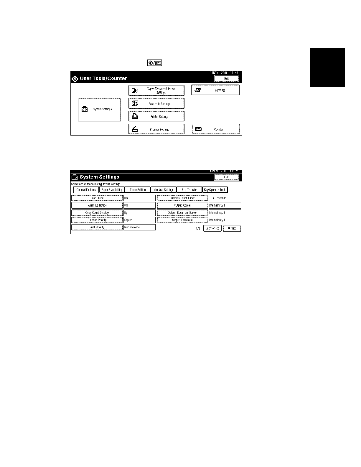
MAIN MACHINE INSTALLATION
SM 1-15 B003/B004/B006/B007
Installation
Set Paper Size for Paper Trays
1. Press User Tools/Counter .
2. On the touch panel, press System Settings.
3. Press the Paper Size Setting tab.
4. Press the button for the tray to change.
5. Change the setting and press the OK button.
6. Repeat for each tray installed.
7. Press Exit twice to return to the main display
• The 1st and 2nd paper trays are provided with paper size dial selectors. The
dial settings on the paper trays have priority over the UP settings. However,
if you select the asterisk (*) position on the paper size dial, you can select the
paper size with the UP setting.
• The 3rd and 4th paper trays of the paper output unit are not equipped with
paper-size selection dials, so you must use the Paper Size UP settings for
the 3rd and 4th trays.
8. Check the copy quality and machine operation.
NOTE: The test pattern print procedure is slightly different for this machine.
Use SP2-902 and select 2 for the IPU Test Print or 3 for the Print Test
Patterns. (☛ Chapter 5, 5.1.3 Test Pattern Printing)
B004I110.WMF
B004I110.WMF
Page 54

MAIN MACHINE INSTALLATION
B003/B004/B006/B007 1-16 SM
Electrical Total Counter
1. Initialize the electrical total counter using SP7-825, depending on the service
contract type.
NOTE: This procedure has an affect only once, when the counter is a
minus (“−“)value.
HDD Caution Decal (for only NA models)
1. Attach the HDD Caution decal [A] to the front cover.
10 mm (0.4")
25 mm (1.0")
B004I017.WMF
B004I018.WMF
[A]
Page 55

PAPER TRAY UNIT INSTALLATION
SM 1-17 B003/B004/B006/B007
Installation
1.4 PAPER TRAY UNIT INSTALLATION
1.4.1 ACCESSORY CHECK
Check the quantity and condition of the accessories in the box against the following
list:
Description Q’ty
1. Knob Screw – M3 .................................................................. 1
2. Knob Screw – M4 .................................................................. 1
3. Joint Bracket.......................................................................... 1
4. Front Stand............................................................................ 1
5. Rear Stand............................................................................. 1
6. Stand Bracket ........................................................................ 1
7. NECR..................................................................................... 1
8. Installation Procedure............................................................ 1
Page 56

PAPER TRAY UNIT INSTALLATION
B003/B004/B006/B007 1-18 SM
1.4.2 INSTALLATION PROCEDURE
!
CAUTION
Switch off the main machine and unplug its power cord before starting the
following procedure.
1. Unpack the paper tray unit and remove all tape [A] and shipping retainers.
2. Remove the paper trays [B].
A682I111.WMF
A682I112.WMF
[B]
[A]
Page 57

PAPER TRAY UNIT INSTALLATION
SM 1-19 B003/B004/B006/B007
Installation
3. Remove the middle front cover [A], and pull out the front handles [B].
4. Using the front handles and rear handles, lift the machine and hold it over the
paper tray unit [C].
5. Slowly lower the main machine onto the paper tray unit with the pegs [D]
aligned with the peg holes on the bottom of the machine.
NOTE: Do not hold the scanner unit.
6. Re-install the middle front cover [A].
7. Attach the lock washer [E] to the short knob screw [F]. Then, secure the paper
tray unit to the machine (! x1, lock washer).
8. Open the right cover of the paper tray unit [G].
9. Secure the joint bracket [H] (! x 1).
10. Remove the connector cover [I] of the main machine (! x1).
11. Connect the paper tray unit harness [J] to the main machine and re-attach the
connector cover.
A682I113.WMF
A682I517.WMF
[A]
[B]
[F]
[C]
[D]
[E]
[D]
[G]
[H]
[I]
[J]
Page 58

PAPER TRAY UNIT INSTALLATION
B003/B004/B006/B007 1-20 SM
12. Install the front and rear stands [A] and [B]. First attach at ! and then swing
the other end round to ".
13. Install the stand bracket [C].
NOTE: The stand bracket must be installed on the left side in order to allow
installation of the Two-Tray Finisher.
A682I118.WMF
A682I119.WMF
[A]
[B]
[C]
LEFT SIDE
Page 59

PAPER TRAY UNIT INSTALLATION
SM 1-21 B003/B004/B006/B007
Installation
14. Position the side fence [A] and bottom fence [B] of the paper trays, load the
paper, and then lock them in position by tightening the hex nuts with the green
wrench [C] provided in the 1st paper tray.
15. Attach the appropriate tray decals [D] provided in the accessory box for the
main machine.
16. Turn on the machine main power switch.
17. Enter the paper size for each paper tray using the UP mode.
18. Check the machine’s operation and copy quality.
A682I120.WMF
A682I500.WMF
[D]
[A]
[B]
[C]
[D]
Page 60

1-BIN TRAY UNIT INSTALLATION
B003/B004/B006/B007 1-22 SM
1.5 1-BIN TRAY UNIT INSTALLATION
1.5.1 ACCESSORY CHECK
Check the quantity and condition of the accessories in the box against the following
list:
Description Q’ty
1. Ground Bracket...................................................................... 1
2. Connector Cover.................................................................... 1
3. Base Cover............................................................................ 1
4. Copy Tray .............................................................................. 1
5. Mylar Strip.............................................................................. 1
6. Stepped Screw – M3x8.......................................................... 5
7. Screw –M3x8......................................................................... 2
8. Screw – M4x7........................................................................ 1
9. Tapping Screw – M3x6.......................................................... 2
10. Tapping Screw – M3x14 ........................................................ 1
11. Tapping Screw – M3x8 .......................................................... 1
12. Installation Procedure ............................................................ 1
Page 61

1-BIN TRAY UNIT INSTALLATION
SM 1-23 B003/B004/B006/B007
Installation
1.5.2 INSTALLATION PROCEDURE
!
CAUTION
Switch off the main machine and unplug its power cord before starting the
following procedure.
1. Remove the scanner unit
NOTE: If the ARDF is installed, remove the ARDF before removing the
scanner unit.
1) Remove the connector cover [A].
2) Disconnect the scanner cable [B].
3) Remove the scanner unit [C] (! x 3).
B376I113.WMF
B376I114.WMF
[A]
[B]
[C]
Page 62

1-BIN TRAY UNIT INSTALLATION
B003/B004/B006/B007 1-24 SM
2. Unpack the 1-bin tray unit and remove the tapes.
3. Remove the front bracket [A] (! x1) and rear bracket [B] (! x1) from the top of
the paper exit cover [C] (! x 1 each).
4. Remove the paper exit cover [C] (! x 4).
5. Cut away two covers [D] from the base cover [E].
6. Trim the edges so they are smooth.
7. Install the base cover [E] (! x 3: stepped screw).
8. Set the 1-bin tray unit [F] on the base cover and slide it onto the heads of the
stepped screws.
B376I201.WMF
B376I102.WMF
[A]
[B]
[C]
[D]
[E]
[F]
Page 63

1-BIN TRAY UNIT INSTALLATION
SM 1-25 B003/B004/B006/B007
Installation
9. Secure the 1-bin tray unit [A] (! x 1: M3x14).
10. Remove the cover [B].
11. Install the grounding bracket [C] (! x 2: M3x6).
12. Connect the harness [D].
13. Install the connector cover [E] (! x 1: M3x8)
14. Re-install the front bracket [F] (! x 2: M4x7, M4x10) and the rear bracket [G]
(! x1 M4x10).
A684I492.WMF
B376I103.WMF
[A]
[B]
[C]
[D]
[E]
[F]
[G]
Page 64

1-BIN TRAY UNIT INSTALLATION
B003/B004/B006/B007 1-26 SM
15. Attach the copy tray.
Bridge Unit (B397) not installed:
1) Attach the decal [A].
2) Secure [B] (! x2: Stepped screw) into the side of the 1-bin tray housing.
3) Attach the copy tray [C] to the stepped screws.
Bridge Unit (B397) installed:
1) Open the cover of the bridge unit [D].
2) Install the copy tray bracket [E] (! x1: tapping screw).
3) Install the copy tray [F] (" x 1).
A684I493.WMF
B376I501.WMF
[A]
[B]
[C]
[D]
[E]
[F]
Page 65
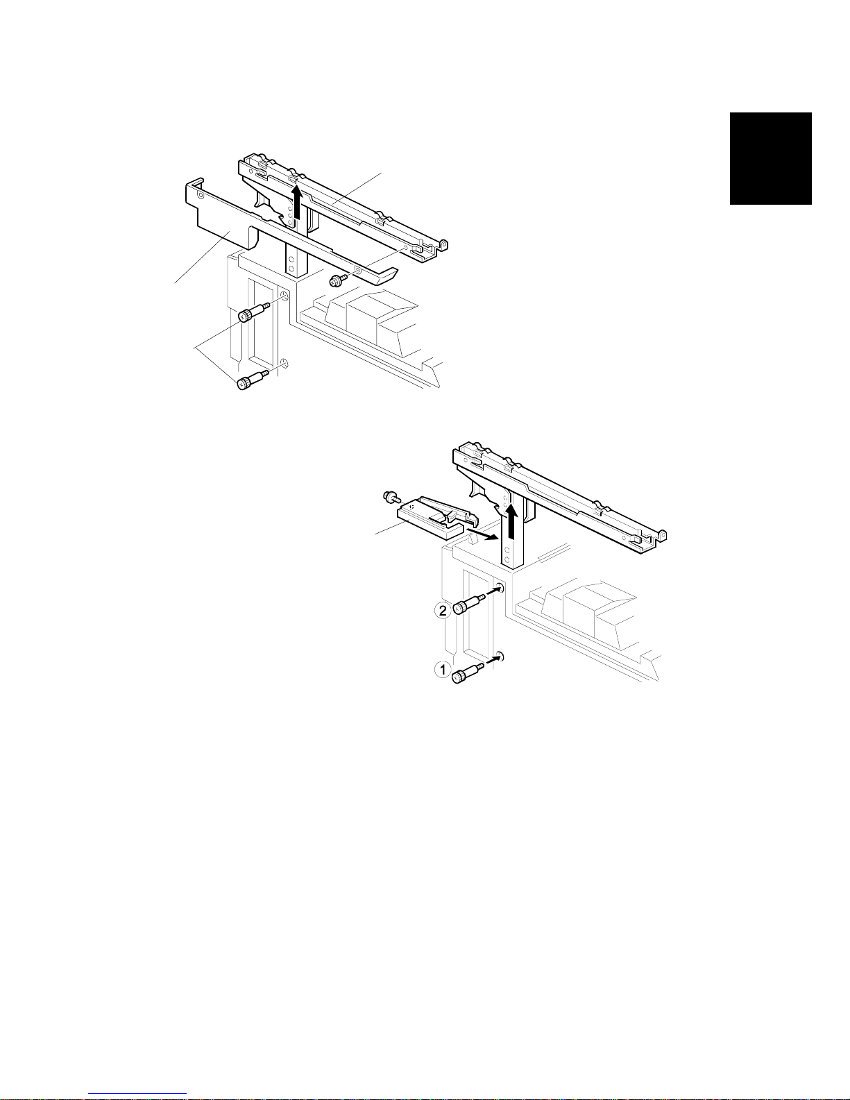
1-BIN TRAY UNIT INSTALLATION
SM 1-27 B003/B004/B006/B007
Installation
16. Remove the scanner stand cover [A] (! x1).
17. To adjust the height of the scanner stand, first remove [B] (! x2) to release the
scanner stand [C].
18. Raise the scanner stand until the next set of screw holes in the main frame can
be seen through the screw holes in the scanner stand.
19. Secure the stand and install the cover [D] (! x1).
B376I104.WMF
B376I105.WMF
[A]
[B]
[C]
[D]
Page 66

1-BIN TRAY UNIT INSTALLATION
B003/B004/B006/B007 1-28 SM
20. Attach two mylar strips [A] to the scanner stand [B].
21. Reinstall the scanner stand cover.
22. Reinstall the scanner unit.
23. Turn on the main switch and check the 1-bin tray unit operation.
B376I106.WMF
[A]
[B]
Page 67

BRIDGE UNIT INSTALLATION
SM 1-29 B003/B004/B006/B007
Installation
1.6 BRIDGE UNIT INSTALLATION
1.6.1 ACCESSORY CHECK
Check the quantity and condition of the accessories in the box against the following
list:
Description Q’ty
1. Stepped Screw ...................................................................... 2
2. Connector Cover.................................................................... 1
3. Exit Mylar............................................................................... 2
4. Installation Procedure............................................................ 1
Page 68

BRIDGE UNIT INSTALLATION
B003/B004/B006/B007 1-30 SM
1.6.2 INSTALLATION PROCEDURE
!
CAUTION
Switch off the main machine and unplug its power cord before starting the
following procedure.
1. Unpack the bridge unit [A] and remove all tapes shipping retainers.
2. Remove the inner tray [B].
3. On the side of the machine, remove the three small covers [C].
If the optional external output tray (A825) will be installed (instead of a
finisher), do Step 4.
4. Remove the two small covers [D].
5. Remove the cover [E] (! x1)
6. Remove the cap [F].
B397I401.WMF
B397I407.WMF
B397I500.WMF
[A]
[B]
[C]
[E]
[F]
[D]
Page 69

BRIDGE UNIT INSTALLATION
SM 1-31 B003/B004/B006/B007
Installation
7. If an optional finisher is to be installed, attach two mylars [A] to the bridge unit.
8. Remove the cover [B].
9. Install the bridge unit [C] (! x2).
10. Connect the bridge unit I/F harnesses [D] (# x2).
11. Install the connector cover [E].
12. Turn on the main switch and check the bridge unit operation (make sure that
there are no paper jams).
A688I402.WMF
B397I404.WMF
[A]
[B]
[C]
[D]
[E]
Page 70

1000-SHEET FINISHER INSTALLATION
B003/B004/B006/B007 1-32 SM
1.7 1000-SHEET FINISHER INSTALLATION
1.7.1 ACCESSORY CHECK
Check the quantity and condition of the accessories in the box against the following
list:
Description Q’ty
1. Front Stand..........................................................................1
2. Rear Stand ..........................................................................1
3. Knob Screw .........................................................................1
4. Screw - M4x12.....................................................................6
5. NECR (-17 machine) ...........................................................1
6. Installation Procedure..........................................................1
Page 71

1000-SHEET FINISHER INSTALLATION
SM 1-33 B003/B004/B006/B007
Installation
1.7.2 INSTALLATION PROCEDURE
!
CAUTION
Switch off the main machine and unplug its power cord before starting the
following procedure.
NOTE: The bridge unit (B397) and paper tray unit (A682) must be installed before
installing this finisher.
1. Unpack the finisher and remove the tapes and retainers.
A681I701.WMF
A681I702.WMF
Page 72

1000-SHEET FINISHER INSTALLATION
B003/B004/B006/B007 1-34 SM
2. Fasten [A] (! x2) loosely.
3. Hang the front stand [B] and rear stand [C] on the screws installed in step 2.
4. To secure the front and rear stands tighten [A] (! x2) and secure the stands (!
x4).
5. At the front, use handle [D] to pull out the stapler unit.
6. Remove the locking lever [E] (! x1).
7. Align the finisher on the stands, and lock it in place by pushing the locking
lever.
8. Secure the locking lever (! x1) and push the stapler unit into the finisher.
A681I705.WMF
A681I704.WMF
[A]
[B]
[C]
[D]
[E]
Page 73

1000-SHEET FINISHER INSTALLATION
SM 1-35 B003/B004/B006/B007
Installation
9. Secure the finisher [A] (! x1).
10. Adjust the securing knobs [B] under the front and rear stands until the finisher
is perpendicular to the floor.
11. Install the shift tray [C] (snap ring x1).
NOTE: Make sure that the three pegs [D] fit into the slots [E] properly.
12. Connect the finisher cable [F] to the main machine.
13. Turn on the main power switch and check the finisher operation.
A681I706.WMF
[A]
[B]
[C]
[D]
[E]
[F]
Page 74

TWO-TRAY FINISHER INSTALLATION
B003/B004/B006/B007 1-36 SM
1.8 TWO-TRAY FINISHER INSTALLATION
1.8.1 ACCESSORY CHECK
Check the quantity and condition of the accessories in the box against the following
list:
Description Q’ty
1. Front Joint Bracket................................................................. 1
2. Rear Joint Bracket ................................................................. 1
3. Shift Tray ............................................................................... 2
4. Screw – M3x6........................................................................ 2
5. Screw – M4x14...................................................................... 4
6. Lower Ground Plate............................................................... 1
7. Installation Procedure............................................................ 1
Page 75

TWO-TRAY FINISHER INSTALLATION
SM 1-37 B003/B004/B006/B007
Installation
1.8.2 INSTALLATION PROCEDURE
!
CAUTION
Switch off the main machine and unplug its power cord before starting the
following procedure.
NOTE: The Paper Tray Unit (A682) and Bridge Unit (B397) must be installed
before installing this finisher. (☛ 1.4, 1.6)
1. Unpack the finisher and remove all tapes and shipping retainers from outside
the unit.
2. Open the front door [A] and remove all tapes and shipping materials from inside
the finisher unit.
B352I101.WMF
B352I102.WMF
[A]
Page 76

TWO-TRAY FINISHER INSTALLATION
B003/B004/B006/B007 1-38 SM
3. Install the left joint bracket [A] (! x2 M4x14) and right joint bracket [B] (! x2
M4x14).
4. Attach the ground plate [C] (! x2 M3x6) to the center of the paper tray.
5. Open the front door of the finisher, and pull out the locking lever [D] (! x1).
6. Push the finisher to the side of the machine with the holes in the finisher
aligned with the joint brackets, and then dock the finisher against the machine.
7. Push in the locking lever and secure it (! x1), then close the front door.
B352I104.WMF
B352I105.WMF
[A]
[B]
[C]
[D]
Page 77

TWO-TRAY FINISHER INSTALLATION
SM 1-39 B003/B004/B006/B007
Installation
8. Install two trays [A] (! x1 each).
9. Connect the finisher cable [B] to the main machine below the right rear handle.
10. Turn on the main switch and check the finisher operation.
NOTE: When moving the finisher to a new location, if you wish to put the finisher
back in the original carton, change the DIP switch settings. See DIP
Switches in the finisher service manual.
B352I103.WMF
B352I106.WMF
[A]
[B]
Page 78

PUNCH UNIT INSTALLATION
B003/B004/B006/B007 1-40 SM
1.9 PUNCH UNIT INSTALLATION
1.9.1 ACCESSORY CHECK
Check the quantity and condition of the accessories in the box against the following
list:
Description Q’ty
1. Punch unit..............................................................................1
2. Sensor arm ............................................................................ 1
3. Hopper...................................................................................1
4. Step screw .............................................................................1
5. Spring .................................................................................... 1
6. Spacer (2 mm).......................................................................1
7. Spacer (1 mm).......................................................................1
8. Tapping screw .......................................................................1
9. Tapping screw .......................................................................2
Page 79

PUNCH UNIT INSTALLATION
SM 1-41 B003/B004/B006/B007
Installation
1.9.2 INSTALLATION PROCEDURE
!
CAUTION
Switch off the main machine and unplug its power cord. If the Two-Tray
Finisher is installed, disconnect it and pull it away from the machine.
(☛ 1.8)
1. Unpack the punch unit and remove all tapes and shipping retainers.
2. Open the front door and remove the rear cover [A] (! x4).
3. Remove the bracket [B] (! x2) and paper guide [C] (! x 1).
B377I102.WMF
B377I103.WMF
[A]
[B]
[C]
Page 80

PUNCH UNIT INSTALLATION
B003/B004/B006/B007 1-42 SM
4. Remove the hopper cover [A] (! x 2).
5. Install the sensor bracket [B] (stepped ! x 1).
6. Install the spring [C].
7. Install the 2 mm spacer [D].
8. Install the punch unit [E] (! x 2, stepped ! x 1)
B377I101.WMF
B377I104.WMF
[A]
[B]
[C]
[D]
[E]
Page 81

PUNCH UNIT INSTALLATION
SM 1-43 B003/B004/B006/B007
Installation
9. Connect the harnesses [A] and clamp them as shown.
NOTE: No special DIP switch settings are required for this punch unit. The
punch unit sends an identification signal to the machine board so it
knows what type of punch unit has been installed.
10. Slide the hopper [B] into the machine.
11. Fasten the two 1 mm spacers [C] to the rear frame for future adjustment.
NOTE: The spacers are used to adjust the horizontal positioning of the holes.
12. Reassemble the finisher and check the punch operation.
B377I105.WMF
B377I106.WMF
[A]
[B]
[C]
Page 82

AUTO REVERSE DOCUMENT FEEDER INSTALLATION
B003/B004/B006/B007 1-44 SM
1.10 AUTO REVERSE DOCUMENT FEEDER
INSTALLATION
1.10.1 ACCESSORY CHECK
Check the quantity and condition of the accessories in the box against the following
list:
Description Q’ty
1. Stepped Screw ...................................................................... 2
2. Screw – M4x10...................................................................... 2
3. Installation Procedure............................................................ 1
Page 83

AUTO REVERSE DOCUMENT FEEDER INSTALLATION
SM 1-45 B003/B004/B006/B007
Installation
1.10.2 INSTALLATION PROCEDURE
!
CAUTION
Unplug the main machine power cord before starting the following
procedure.
1. Unpack the ARDF and remove all tapes and shipping retainers.
2. Attach and tighten [A] (! x2 stud).
3. Mount the ARDF by aligning the screw keyholes [B] of the ARDF support plate
over the stud screws, and slide the ARDF toward the front of the machine.
NOTE: To avoid damaging the ARDF, hold it as shown in the illustration.
4. Secure the ARDF [C] (! x2).
B351I122.WMF
B351I123.WMF
[A]
[B]
[C]
Page 84

AUTO REVERSE DOCUMENT FEEDER INSTALLATION
B003/B004/B006/B007 1-46 SM
5. Connect the I/F cable [A] (# x1) to the main machine.
6. Turn on the main switch.
7. Check the ARDF operation and copy quality. Be sure to check and adjust the
registration for the ARDF with SP 6006.
B351I124.WMF
[A]
Page 85

LCT INSTALLATION
SM 1-47 B003/B004/B006/B007
Installation
1.11 LCT INSTALLATION
1.11.1 ACCESSORY CHECK
Check the quantity and condition of the accessories in the box against the following
list:
Description Q’ty
1. Joint Pin................................................................................. 2
2. Stepped Screw M3x18........................................................... 4
3. Magnet Cover ........................................................................ 1
4. NECR (-17, -27 machines)..................................................... 1
5. Installation Procedure............................................................ 1
Page 86

LCT INSTALLATION
B003/B004/B006/B007 1-48 SM
1.11.2 INSTALLATION PROCEDURE
!
CAUTION
Switch off the main machine and unplug its power cord before starting the
following procedure.
NOTE: The Paper Tray Unit (A682) must be installed before installing the LCT.
(☛ 1.4)
1. Unpack the LCT and remove the tapes.
2. Open the right cover [A] of the paper tray unit.
3. Open the lower right cover [B] and cut the holding band [C].
NOTE: When cutting the holding band, the upper part of the band should be
cut as shown. Otherwise, paper jams may occur.
4. Remove the right lower cover.
A683I501.WMF
A683I604.WMF
A683I500.WMF
[B]
[C]
[A]
Page 87

LCT INSTALLATION
SM 1-49 B003/B004/B006/B007
Installation
6. Install the joint pins [A].
7. Push the release lever [B] and slide the LCT to the right (front view).
8. Hang the LCT [C] on the joint pins, then secure the brackets [D] (! x4).
9. Return the LCT to the previous position and connect the LCT cable [E].
10. Open the LCT cover and load the paper.
11. Turn on the ac switch and check the LCT operation.
A683I503.WMF
[B]
[D]
[C]
[E]
[A]
Page 88

PLATEN COVER INSTALLATION
B003/B004/B006/B007 1-50 SM
1.12 PLATEN COVER INSTALLATION
1. Install [A] (! x2) on the top cover as shown.
2. Position the platen cover bracket [B] on the heads of the stud screws and slide
the platen cover [C] to the left.
A683125.WMF
[B]
[C]
[A]
[A]
Page 89

KEY COUNTER INSTALLATION
SM 1-51 B003/B004/B006/B007
Installation
1.13 KEY COUNTER INSTALLATION
!
CAUTION
Unplug the machine power cord before starting the following procedure.
1. Hold the key counter plates [A] on the inside of the key counter bracket [B] and
insert the key counter holder [C]
2. Secure the key counter holder to the bracket (! x2).
3. Attach the key counter cover [D] (! x2).
4. Remove the connector cover [E].
5. Remove the knockout [F] from the connector cover.
6. Remove the rear upper cover [G] (! x4) and left corner cover [H] (! x2).
A683I001.WMF
A683I518.WMF
[E]
[F]
[G]
[H]
[B]
[C]
[D]
[A]
Page 90

KEY COUNTER INSTALLATION
B003/B004/B006/B007 1-52 SM
7. Connect the key counter connector [A] to CN211 on the I/O board.
8. Reinstall the covers [B] and [C].
9. Attach the double-sided tape to the key counter bracket.
10. Peel off the backing of the double-sided tape and attach the key counter
assembly [D] to the left side of the scanner unit.
NOTE: When attaching the key counter assembly, press the assembly hard
against the scanner cover. Otherwise, the key counter assembly may
come off easily.
11. Set “User Tools”, “System Settings”, “Key Operator Tools”, and “Key Counter
Management” to restrict access to each available function mode.
A683I003.WMF
A683I002.WMF
A683I965.WMF
[A]
[D]
[C]
[B]
Rev. 04/2002
⇒
Page 91

ANTI-CONDENSATION HEATER
SM 1-53 B003/B004/B006/B007
Installation
1.14 ANTI-CONDENSATION HEATER
1. Remove the ARDF and exposure glass.
NOTE: For details about how to remove the ARDF and exposure glass, see
section “3 REPLACMENT AND ADJUSTMENT”, sections 3.9.1 and
3.9.2.
2. Remove the rear cover [A] of the scanner
unit (! x2, # x1)
3. Remove the knockout [B]
4. Push the 1st and 2nd scanners [C] to
the right.
5. Lift the harness guide [D]
6. Install the heater brackets [E] (! x2,
M3x6).
NOTE: Use the screws already attached
at the same position.
7. Install the heater [F] (! x2, M4x6) and
route the harness.
B004I204.WMF
B004I205.WMF
B004I206.WMF
[A]
[B]
[C]
[D]
[E]
[F]
Page 92

ANTI-CONDENSATION HEATER
B003/B004/B006/B007 1-54 SM
8. Install the ac harness assembly [G] (! x2,
M4x6) and connect the connector [H].
9. Remove the rear lower cover [I] (! x4).
10. Remove knockout [J].
11. Pull out ac harness [K].
12. Connect the ac harness [L] to the ac outlet
[M].
NOTE: Do not remove the ground wire
from the ac outlet.
13. Install the ac outlet.
14. Install the ground wire [N] (! x1, M4x6).
15. Re-install the rear cover, rear lower cover.
16. Connect the harness [O].
B004I208.WMF
B004I209.WMF
B004I210.WMF
[G]
[H]
[I]
[J]
[K]
[L]
[M]
[N]
[O]
Page 93

TRAY HEATER
SM 1-55 B003/B004/B006/B007
Installation
1.15 TRAY HEATER
!
CAUTION
Unplug the machine power cord before starting the following procedure.
1. Attach the tray heater [A] to the heater bracket [B].
2. Install the harness holder [C].
3. Remove the rear lower cover.
4. Remove the upper and lower paper trays from the main machine.
5. Install the heater assembly [D] (! x1).
6. Install the harness clamp [E].
7. Fasten the harness [F] with the clamp.
8. Route the heater harness [G] and connect it to the ac harness [H].
A284I531.WMF
B004I203.WMF
B004I202.WMF
[A]
[B]
[C]
[D]
[E]
[G]
[F]
[H]
Page 94

TRAY HEATER (OPTIONAL PAPER TRAY UNIT)
B003/B004/B006/B007 1-56 SM
1.16 TRAY HEATER (OPTIONAL PAPER TRAY UNIT)
!
CAUTION
Unplug the machine power cord before starting the following procedure.
1. Attach the optional tray heater [A] to the heater bracket [B].
2. Install the harness holder [C].
3. Remove the rear lower cover of the machine and the rear cover of the optional
paper tray unit.
4. Remove the upper and lower paper trays of the optional paper tray unit.
5. Install the heater assembly [D] (! x1).
6. Install four harness clamps [E].
7. Route the harness [F] and connect it to the harness [G] and heater harness [H].
A284I601.WMF
B004I201.WMF
B004I531.WMF
[G]
[H]
[E]
[F]
[D]
[A]
[B]
[C]
Page 95

OPTIONAL USER ACCOUNT ENHANCEMENT UNIT
SM 1-57 B003/B004/B006/B007
Installation
1.17 OPTIONAL USER ACCOUNT ENHANCEMENT UNIT
1. Remove the controller PCB.
2. Install the user account enhancement unit (NVRAM) into IC 10 socket on the
controller PCB.
3. Re-install the controller PCB.
Rev. 04/2002
⇒
Page 96

Page 97

PREVENTIVE MAINTENANCE
Page 98

Page 99

PM TABLE
SM 2-1 B003/B004/B006/B007
Preventive
Maintenance
2. PREVENTIVE M AINTENANCE SCHEDULE
2.1 PM TABLE
NOTE: Amounts mentioned as the PM interval indicate the number of prints.
Symbol key: C: Clean, R: Replace, L: Lubricate, I: Ins pect
B003/B004B006/B007 EM 150K 300K 450K NOTE
SCANNER/OPTICS
Reflector C C C Optics cloth
1st Mirror C C C Optics cloth
2nd Mirror C C C Optics c loth
3rd Mirror C C C Optics cloth
Scanner Guide Rails
III
Do not use alcohol. Lubricate
if necessary.
Platen Sheet Cover
CI I I
Dry cloth or alcohol. Repla c e
platen sheet if required.
Exposure Glass C C C Dry clot h or alcohol
Toner Shield Glass C C C Optics cloth
APS Sensor C C C Dry cloth or alc ohol
Exposure Glass (Sheet
through)
CCC
Dry cloth or alcohol
DRUM (OPC) AREA
Charge Roller R R R
Charge Roller Cleaning
Pad
RRR
Quenching Lamp C Dry cloth
Pick-off Pawls R R R
Spurs C C C Dry cloth or alc ohol
ID Sensor
CCC
Perform SP3-001-2 after
blower brush cleaning.
CLEANING UNIT
Drum Cleaning Blade R R R
Cleaning Entrance S eal
CCC
Blower brush. Replace if
required.
Side Seal I I I
Page 100

PM TABLE
B003/B004/B006/B007 2-2 SM
B003/B004B006/B007 EM 150K 300K 450K NOTE
DEVELOPMENT UNIT
Development Drive
Gears
III
Development Filter R R R
Developer I R I
Entrance Seal I I I
Side Seal I I I
Development Roller C C C Dry cloth
PAPER FEED
Registration Roller CCCCWater or alcohol.
Paper Feed Roller I R R R
Separation Roller I R R R
Pick-up Roller I R R R
Paper Feed Roller (By-
pass feed table)
I RRR
Separation Roller (Bypass feed table)
I RRR
Pick-up Roller
(By-pass feed table)
I RRR
Check counter value for
each (SP7-204). If ≥ 150 K,
replace roller. After replacing
the roller, do SP7-816 to
reset counter.
Paper Feed Guides C C C Water or alcohol.
Relay Rollers C C C Water or alcohol.
Bottom Plate Pad C C C Water or alcohol.
Bottom Plate Pad (By-
pass feed)
CCC
Water or alcohol.
Registration Sensor C C C Blower brush
Paper Feed Roller Gear
LLL
Silicone Grease G-501. See
note below.
1
DUPLEX UNIT
Upper Transport Roller C C C Water or alcohol.
Lower Transport Roller C C C Water or alcohol.
TRANSFER BELT UNIT
Transfer Belt CRRRDry cloth
Transfer Belt Cleaning
Blade
RRR
Transfer Belt Rollers C C C Dry cloth
Entrance Seal C C C Dry cloth
Transfer Entrance
Guide
CCCC
Dry cloth
Used Toner Tank I C C C Empty the tank.
 Loading...