

Page 1
TAURUS 1-2-3
Repair Instructions
GESIPA Blindniettechnik GmbH
Nordendstraße 13-39
D-64546 Mörfelden-Walldorf
Telefon +49 6105 / 962-0
Telefax +49 6105 / 962-287
Internet
E-Mail
Page 2
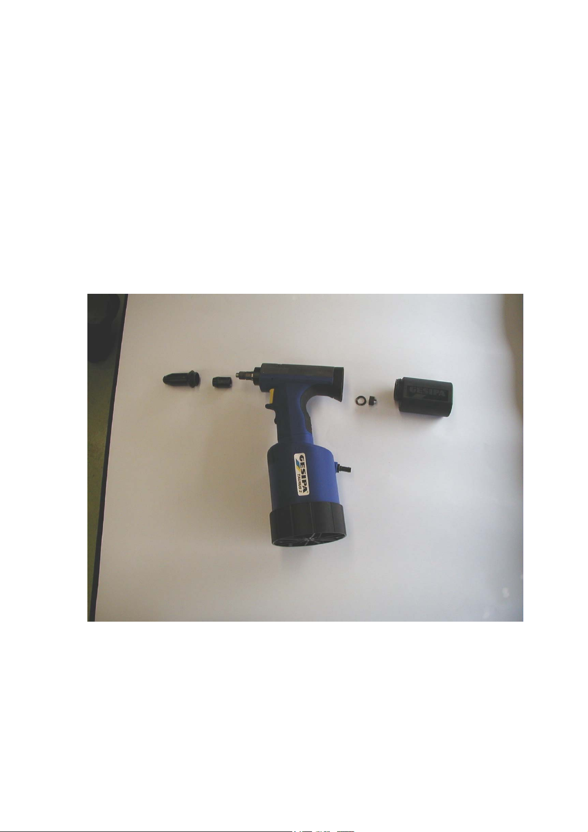
This document shows the chronology of the disassembling of the Taurus tool
series, illustrated by corresponding pictures. This operation necessitates the use
of special tools which are separately listed. Special procedures which must be
followed are described in details and pictured. Reference is also made to the
operating instructions booklet as well as to the illustrated parts price list.
•
Disconnect the tool from the air pressure supply
• Unscrew head (24)
• Unscrew jaw housing (16)
• Unscrew rest mandrel container (103/104)
• Unscrew pressure pipe screw (43a,43) with spring washer (49)
•
Re-install the rest mandrel container (103/104)
1
Page 3
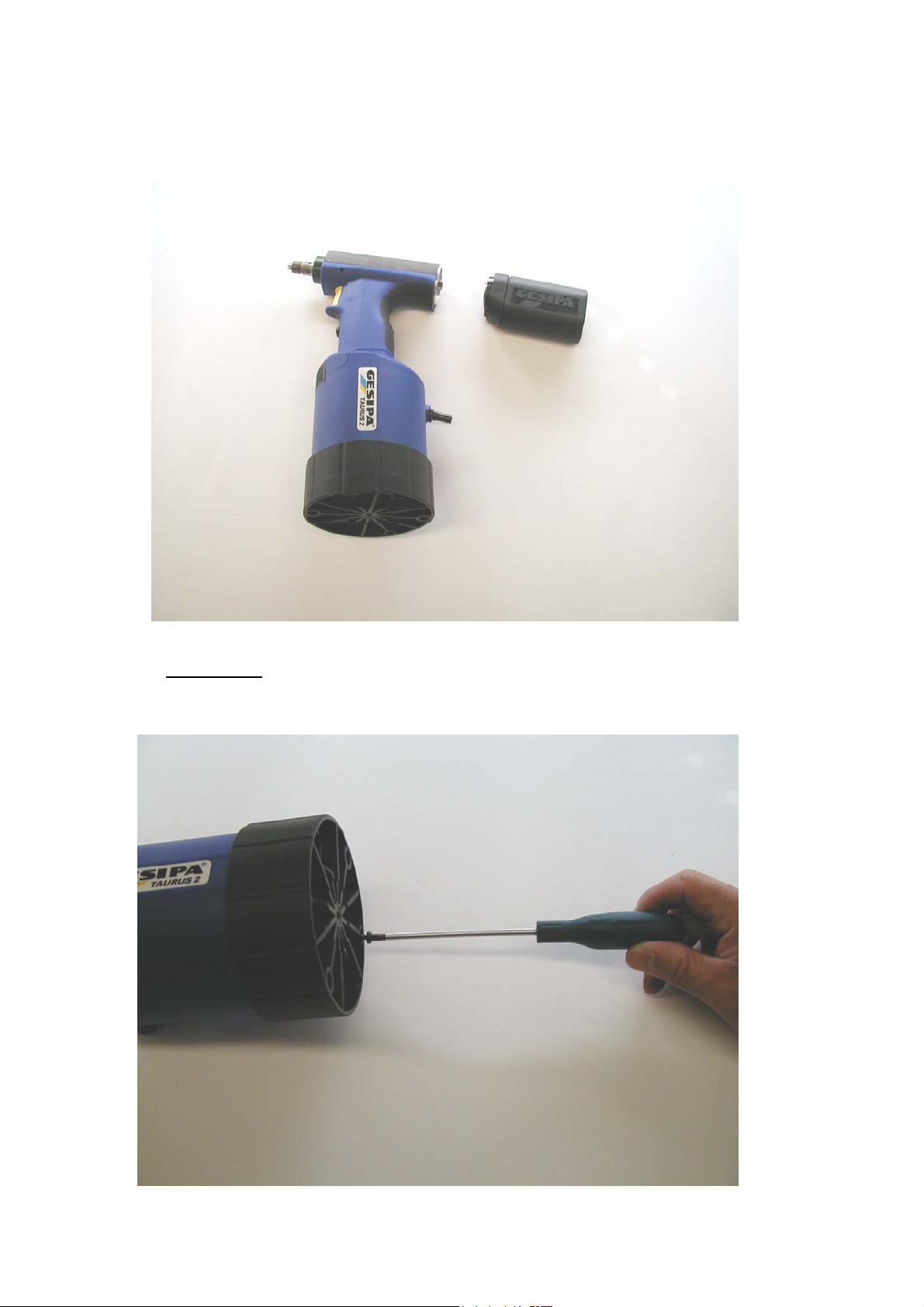
• Pull-off adapters (42) with lock (41) and retaining spring (48) using the
rest mandrel container itself
•
Important: Remove the housing screw from tool bottom. This screw is
maintaining the tool bottom in place and prevents its separation from the
tool.
2
Page 4
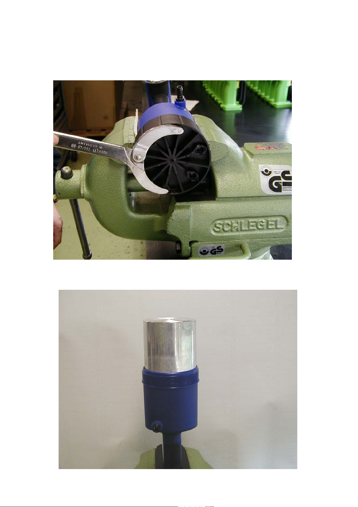
• Carefully install the main cylinder in a vice.
•
Unscrew tool bottom (76,77,78) using a wrench for twin holed nuts
according to DIN 3116.
Install th
•
• Extract the aluminium cylinder(69,70,71)
e tool into the clamping jig ( Special tool )
3
Page 5
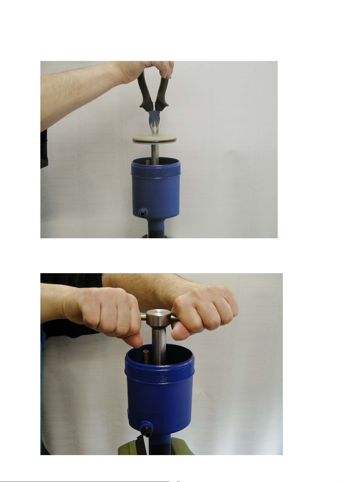
Extract the air piston (72,73,74) using a plier
Un
•
screw Alu nut (57) using the special wrench P/N: 143 5672
4
Page 6
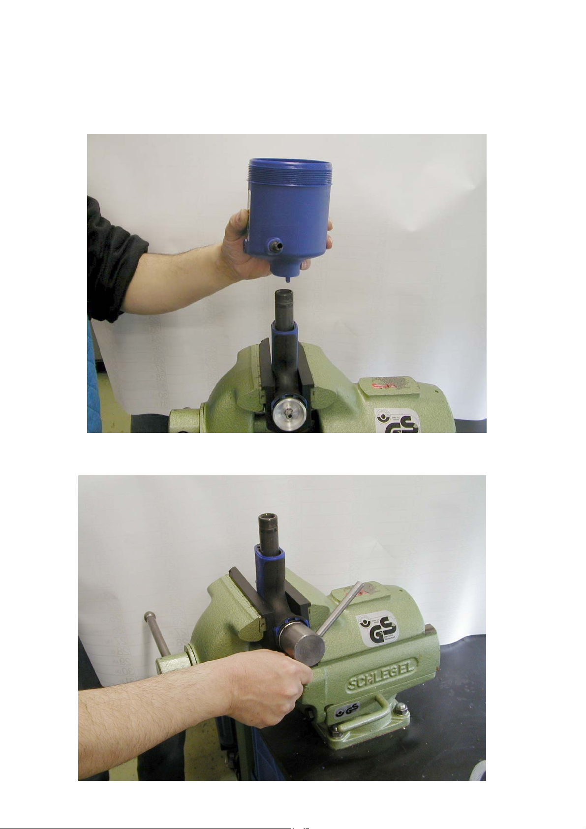
• Carefully remove the complete air cylinder housing (58,59,60) from the
aluminium tube
•
Take great care of not damaging O- Ring (56) !
•
Unscrew the rear screw plug (40) using special wrench P/N 144 6031
5
Page 7
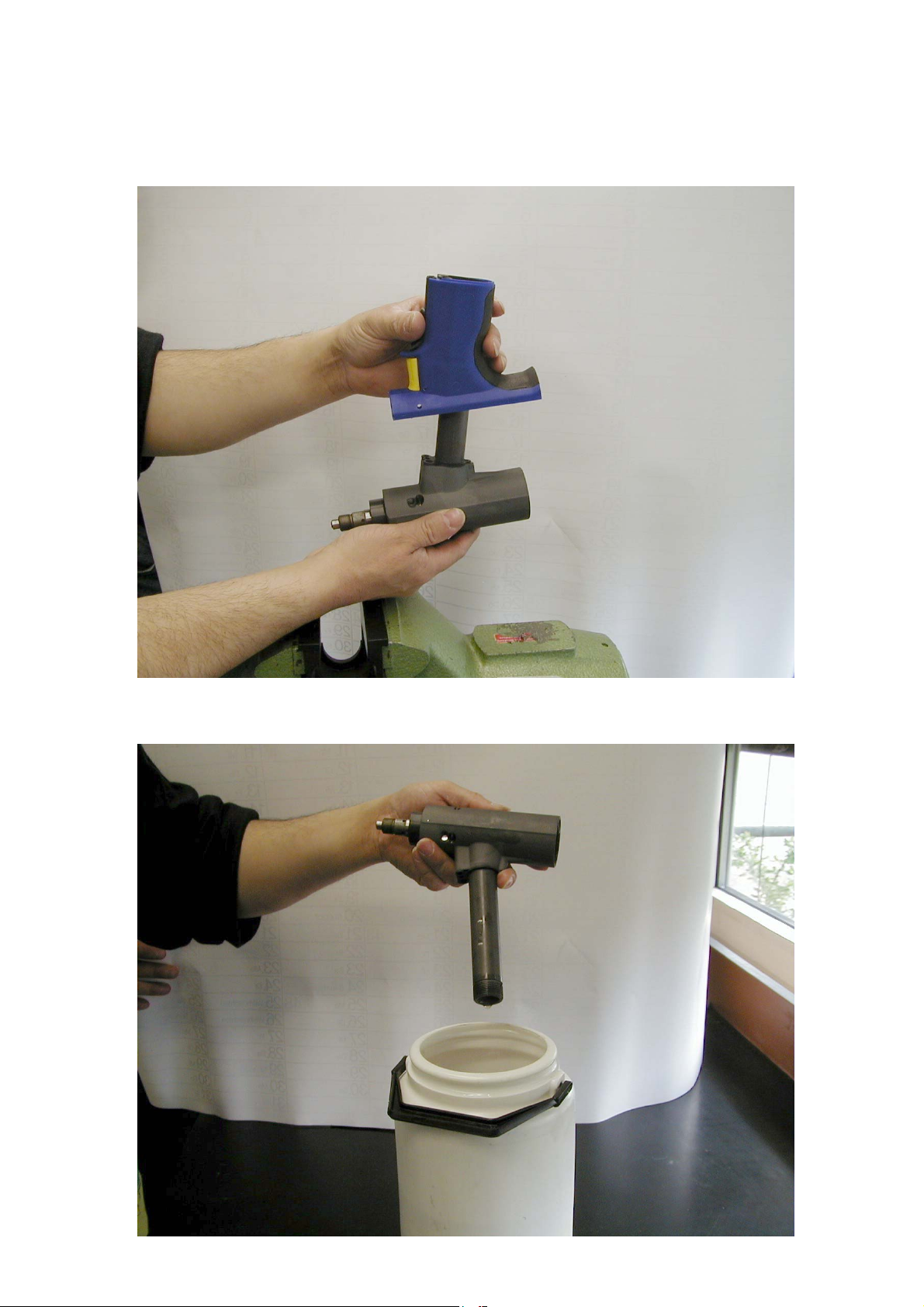
• Remove the tool head from the clamping jig
•
Remove the complete grip section
• Empty the hydraulic fluid into an adequate container
6
Page 8
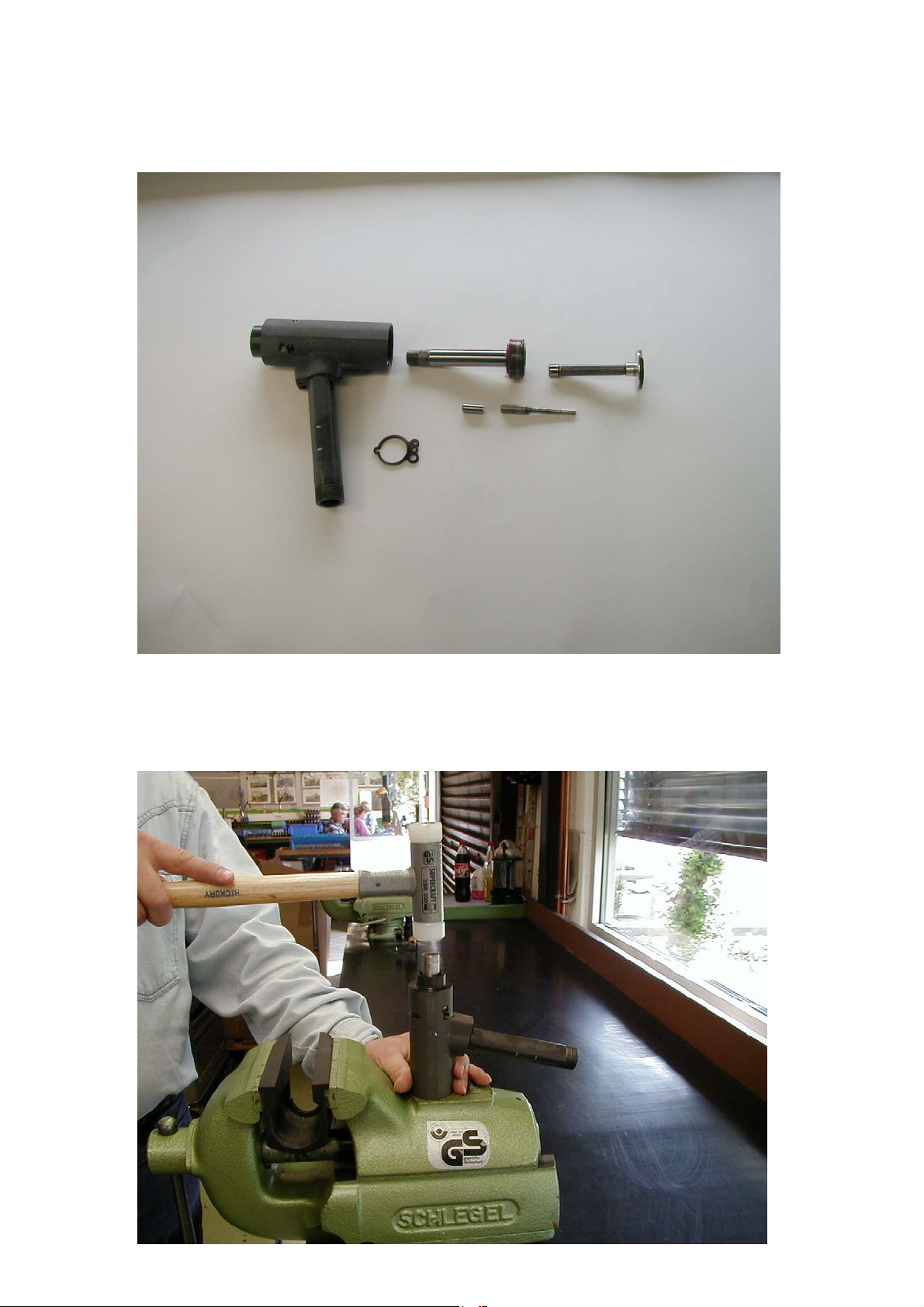
• Push traction rod (25) backwards out of the tool head
•
Remove reset plunger (36) from the traction rod
• Use a 17mm dia. Alu or plastic stamp for removal of the sealing ring
holder (32
• Plug the stamp into front of tool head and eject carefully the sealing ring
holder using a light hammer.
7
Page 9
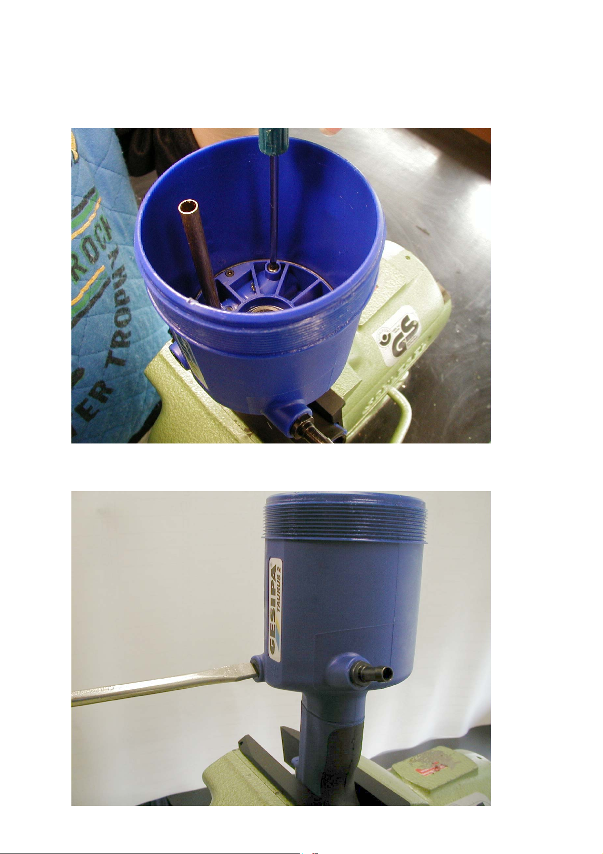
Proceed as follows in case the control valve (see cut A-A in operating
instructions)has to be removed from the air cylinder housing (58,59,60):
• Remove screw (75) using a T20 Torx screw driver
• Unscrew the safety valve (90) using an adequate screw driver
8
Page 10
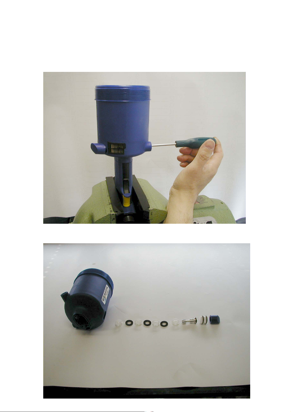
• Use an adequate tool to push out the control piston (92) and the plug
(96,97,98) from the side of the safety valve
•
Push the airzet rod sealings (93) and spacer cage (91) out of the air
cylinder housing.
• Order of sequence of the different components of the control valve.
9
Page 11
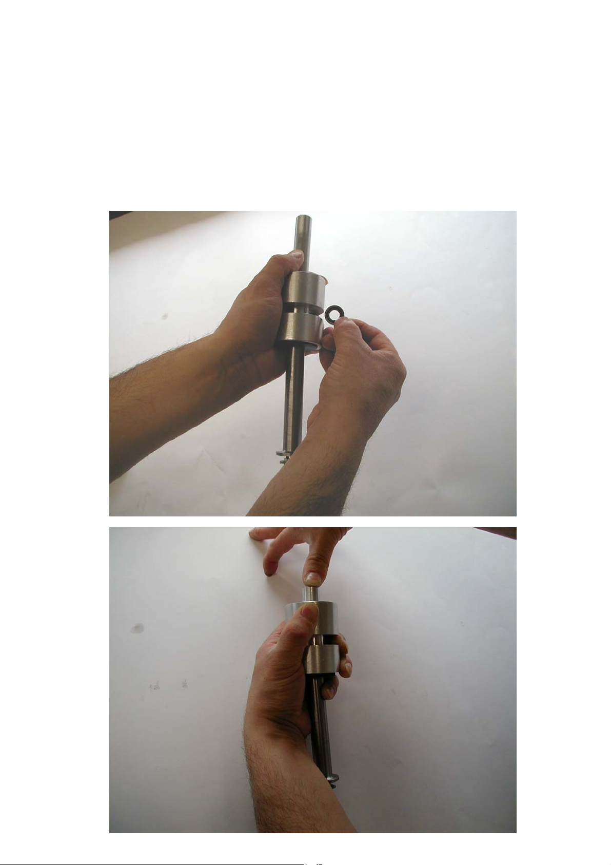
•
Re-installatio
n of the control valve into the tool requires the use of the
spezial Mounting tool for airzet ring, P/N 143 5674.
• Use this tool as follows :
1. Insert introduction help into base body
2. Drop Airzet ring into side slit.
3. Insert stamp from above and carefully push down until you feel the
airzet ring engaging into the introduction help.
4. Pull the introduction help down
10
Page 12
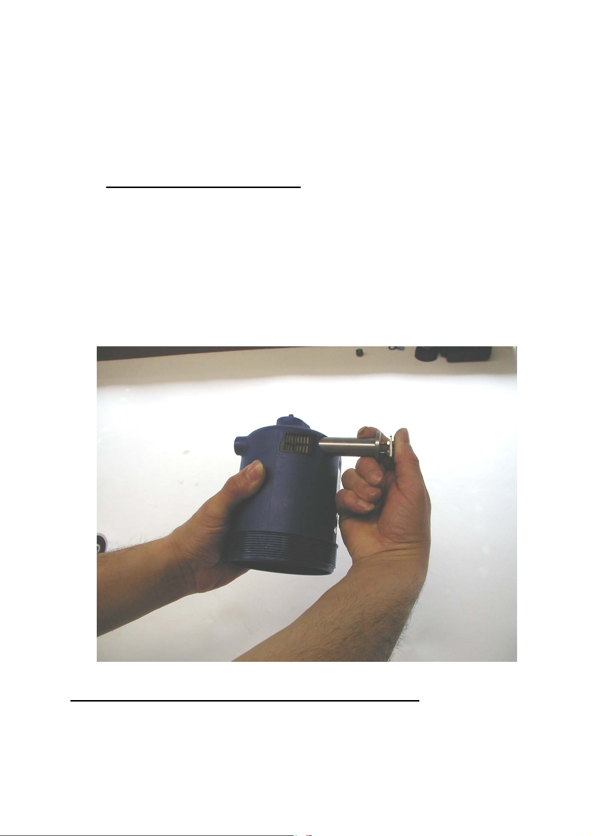
• Push the introduction help sideways into the air cylinder housing.
•
Push with your thumb on the base of the introduction help and then pull
back with your fingers until Stop.
•
Grease the Airzet-Ring
•
Mount all parts following the drawings shown in the operating instruction
booklet or on the spare parts price list.
•
Warning : Important notice:
Take good care of correct installation of the distance cage (91) into the
control valve of the Taurus 2 and 3 to
on one side. Insert the distance cage with the slotted side first in such a
way that the slot connects with the nose inside the control valve bore.
Installation of the 3 following distance cages is indifferent.
The first distance cage is not present in the Taurus 1. Installation of the 3
distance cages is indifferent.
ols. The distance cage carries a slot
Re-assembling the tool is done in reversed sequence
11
 Loading...