

Page 1
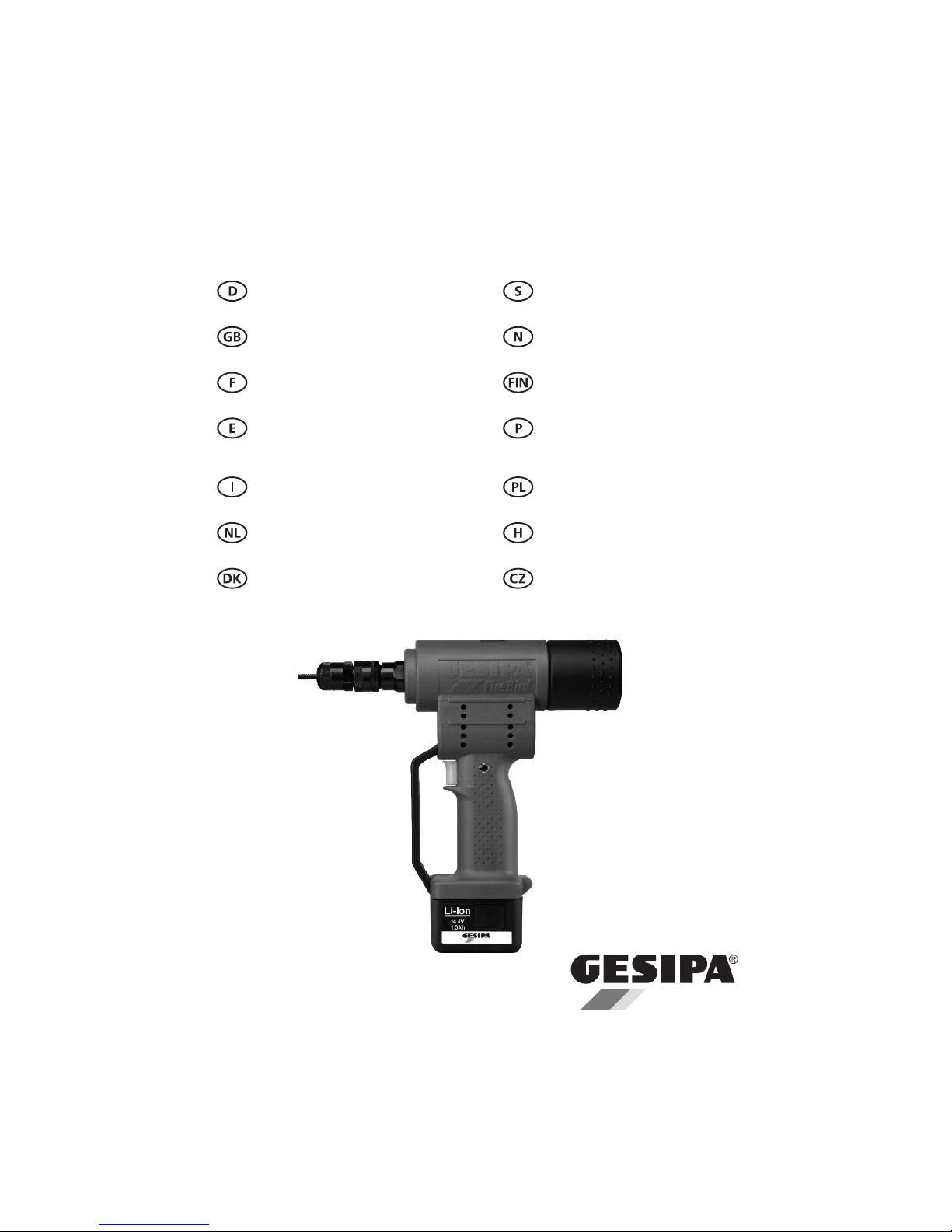
Batteridriven sättapparat
för blindnitmuttrar
Bruksanvisning med reservdelslista
Batteripistol for
blindnaglemuttere
Bruksanvisning med reservedelliste
Akkukäyttöinen
niittimutteripistooli
Käyttöohje ja varaosalista
Máquina de acumulador para
rebitagem de porcas cegas
Instrução de serviço com lista
de peças de reposição
Nitownica akumulatorowa do
nitonakre˛tek
Instrukcja obsługi
wraz ze spisem cze˛sci zamiennych
Akku-Szegecsanyhúzó-készülék
Üzemeltetésiutasítás,
alkatrészlistával
Akumulátorová nytovacˇka
na matice
Návod k obsluze s listinou
náhradnich dilu
Akku-Blindnietmutternsetzgerät
Betriebsanleitung mit Ersatzteilliste
Battery Operated
Blind Rivet Nut Tool
OperatingManual with Spare Parts List
Outil de pose d’écrous
aveugles à batterie
Mode d’emploi a
vec pièces de rechange
Remachadora eléctrica con batería
para remache-tuerca
Instrucciones de
manejo con lista
de repuertos
Rivettatrice ad accumulatore
Manuale per l’uso e la manutenzione
ed elenco parti di ricambio
Accu blindklinkmoer pistool
Bedienings- en onderhouds
handleiding met onderdelenlijst
Akku-blindnittepistol
til blindnittemøtrikker
Betjeningsvejledning med
reservedelsliste
GESIPA Blindniettechnik GmbH
Nordendstraße 13-39
64546 Mörfelden-Walldorf
Germany
T +49 (0) 6105 962 0
F +49 (0) 6105 962 287
[email protected]
www.gesipa.com
FireBird
®
Page 2

Contents page
1. Overview (drawing1 to 5) .................................................................................... 10
2. Blind rivet nut setting tool
2.1. Working capacity....................................................................................................... 10
2.2. Equipment/Accessories.............................................................................................. 10
2.3. Technical data............................................................................................................. 11
2.4. Threaded mandrels and nosepieces, rivet nuts per charge................................... 11
2.5. Safety instructions...................................................................................................... 11
2.6. Starting procedure..................................................................................................... 11
2.6.1. Adjustment of threaded mandrel x (drawing 2)......................................... 11
2.6.2. Stroke adjustment y (drawing 2).................................................................. 11
2.7. Operating procedure ................................................................................................. 12
2.7.1. Threading on a blind rivet nut....................................................................... 12
2.7.2. Setting a blind rivet nut.................................................................................. 12
2.7.3. Change of threaded mandrel 1 (drawing 3)................................................ 12
3. Charger and battery
3.1. Technical data............................................................................................................. 12
3.1.1. Charger ............................................................................................................ 12
3.1.2. Battery ............................................................................................................. 12
3.2. Safety instructions...................................................................................................... 12
3.2.1. Charger ............................................................................................................ 12
3.2.2. Battery ............................................................................................................. 13
3.3. Charging procedure................................................................................................... 13
3.4. Battery handling ........................................................................................................ 13
3.5. Environmental protection .......................................................................................... 13
4. Troubleshooting........................................................................................................... 14
5. Warranty........................................................................................................................ 14
6. Conformity declaration.................................................................................... 14
7. Spare parts drawing ................................................................................................ 77
8. Spare parts list ............................................................................................................ 77
10
2. Blind rivet nut setting tool
2.1. Working capacity
Blind rivet nuts from M3 to M8 in alu and steel
as well as M10 in alu.
2.2. Equipment/Accessories
Threades mandrel M6 in working
and nosepieces: position,
M4 and M5 in holder
M3, M8, M10
available as special
accessory on request
Wrench: 1 hexagon wrench SW4
Suspension loop: concealed in housing
Quick charger: 230 V AC, 50 Hz
Battery: 14,4 V DC
!
1. Overview (see drawing1-5; Page 3)
Pos. Description Drawing
1 Threaded Mandrel 2
2 Nosepiece 2
3 Lock Nut 2
4 Adjusting Nut 2
5 Lock Nut 2
6 Suspension Loop 1
7 Cap 1
8 Screw Driver 1
9 Accessories Container 1
10 Control Light 1
11 Trigger 1
12 Battery 1;5
13 Slide Lock 3
14 Charging Control Light 5
15 Battery Charger 5
16 Set Blind Rivet Nut 4
x Length of Threaded Mandrel 2
y Setting Stroke 2
z Grip Range 4
Page 3
2.5. Safety instructions
Blind rivet nut setting tool FireBird
®
Caution :
Following safety rules must be followed
for adequate protection against electrical shock,
injuries or fire hazards:
•
The tool should be used exclusively to set blind
rivet nuts.
•
Do not overload the tool; Work within the prescribed work capacity.
•
Do not expose the tool to humidity or rain, do
not operate the tool close to inflammable substances or gases. Risk of explosion!
•
Ensure that the battery is properly secured in
the tool handgrip.
•
Remove the battery when the tool is not in use
and for repair/servicing operations.
•
Do not use the tool as a hammer.
•
When not in use, keep the tool in a dry closed
room, out of reach of children.
•
When working with the tool, always carry protection goggles. Personal protection like clothes,
gloves, safety helmet, non slipping shoes, ear
protectors and protection against fall are highly
recommended.
•
The air inlets for the engine should not be ob structed. Do not introduce anything into them.
•
When depositing the tool, make sure that it
cannot fall down.
•
Use only genuine spare parts for repair.
•
Repair work must be carried out by skilled personal. In case of doubt, always send back the
tool to the manufacturer.
2.6. Starting Procedure
Before starting read and follow operating
manual carefully!
2.6.1. Adjustment of threaded
mandrel length x (drawing 2)
– By turning the nosepiece 2 adjust the threaded
mandrel length x to the blind rivet nut length.
– In case of closed end rivet nuts (drawing 2; 4)
use full length of thread.
– Lock nosepiece 2 with lock nut 3 against shifting.
2.6.2. Adjustment of stroke
y (drawing 2)
– The stroke y depends on the blind rivet unit size
(M3 – M10) and the grip range z (drawing 4).
Recommended value for stroke y:
Thread Stroke y(in mm)
size min max
M3 1 2
M4 1 2
M5 1,5 2,5
M6 2,5 3,5
M8 2,5 3,5
M10 3 4
– The stroke y is adjusted by screwing in or out
the adjustment nut 4.
!
2.3. Technical Data
Weight: 2,3 kg (with battery, without
accessories container)
Max. stroke: 5,5 mm
Operating voltage: 14,4 V DC
Traction power: 13.000 N
Noise emission:
LPA 76,5 dB
Vibrations: < 2,5 m/s
2
2.4. Threaded Mandrels and Nosepieces
Rivet Nuts per Charge
Blind rivet Material Rivet nuts Part number
nut inner per Threaded Nosepiece
thread charge Mandrel
M3 Alu 600 7262019 7262086
Steel 550
M4 Alu 520 7262027 7262094
Steel 480
M5 Alu 480 7262035 7262108
Steel 400
M6 Alu 400 7262043 7262116
Steel 300
M8 Alu 340 7262051 7262124
Steel 180
M10 Alu 300 7262078 7262132
11
Page 4

12
Important:
– To start with, the stroke y is to be set
to “min” and then a blind rivet nut is
to be set.
– If the blind rivet nut does not – as shown
in drawing 4 – form a distinctive head (
➚
), the
stroke must be enlarged step by step.
– Lock adjustment nut 4 with lock nut 5 against
shifting.
2.7. Operating Procedure
2.7.1. Threading on a Blind Rivet Nut
– Place blind rivet nut – without tilting it –
on the end of the threaded mandrel.
– Keep trigger 11 pressed until tool
comes to a stop; afterwards release.
– Hold blind rivet nut tight during the entire
threading on procedure.
– If the blind rivet nut is not tight against the
nosepiece 2 after having been threaded on,
the threading procedure must be repeated.
For this purpose hold the blind rivet nut tight
and a short quick touch of the trigger 11 will
induce threading out procedure. Now repeat
threading on.
2.7.2. Setting a Blind Rivet Nut
– Insert drilled-on blind rivet nut into the rivet hole
completely to end position.
– Press trigger 11 and hold it until setting and
automatic threading out are finished.
2.7.3. Change of Threaded mandrel 1
(drawing 3)
– Unscrew nosepiece 2.
– Push head slide 13 to the rear end.
– Unscrew and exchange threaded mandrel 1.
– Bring hexagon area of screwed in threaded
mandrel 1 to match hexagon area of locking
socket.
– Lock the threaded mandrel 1 by pulling the
head slide 13 back to the end position.
– Screw on proper nosepiece 2, adjust threaded
mandrel length x (see 2.6.1.) and secure nose piece 2 with lock nut 3 against torsion.
3. Charger and battery
3.1. Technical characteristics
3.1.1. Battery charger
Type: 12355/12356
Input voltage: 220-240VAC/50-60Hz
Output voltage: 14,4VDC
Output current: 1,5A max.
Weight: 0,6kg
3.1.2. Battery
Nominal voltage: 14,4VDC
Number of cells: 4/8
Cell: Li-Ion
Capacity: 1,3Ah/2,6Ah
Weight: 0,35/0,5kg
3.2. . Safety Instructions
3.2.1. Battery charger
Caution:
Following safety rules must be followed
for adequate protection against electrical shock,
injuries or fire hazards:
•
The charger must be exclusively used to charge
GESIPA batteries.
•
Check regularly cord, plug and device and have
it fixed by skilled personal when damaged.
•
Use exclusively genuine plugs and cords and
genuine spare parts for repair.
•
Never use the charger in humid or wet environment, or close to inflammable substances or
gases: Explosion hazard!
•
Take the charger out of its package before use.
Insert the battery in the right way (pole+ to
pole+) into the charger bay. Insertion should
take place without noticeable effort.
•
Never try to charge non rechargeable batteries.
•
Store the charger in a dry closed room, out f
reach of children.
•
Never insert metallic parts into the charging
bay: Short circuit hazard.
•
When the charger is wall-mounted, make sure
that the inserted battery cannot fall down.
•
Do not operate this battery charger at altitudes
exceeding 2.000 meter above sea level.
!
Page 5
!
13
•
This battery charger should not be operated
neither by physically disabled or mentally
affected people, nor by untrained or unskilled
people.
3.2.2. Battery
Caution:
Following safety rules must be followed for adequate protection against electrical
shock, injuries or fire hazards:
•
Never try to charge a damaged battery.
•
Do not insert a dirty or wet battery into the
charger.
•
Never throw batteries into the waste, into fire
or into water.
•
Do not charge a battery when the environment
temperature is below 0°C.
3.3. Charging procedure
•
Charge only GESIPA batteries when the environment temperature is between 0°C and 40°C.
•
Take the charger out of its package and
connect to mains. Check the input voltage on
the type label before connecting.
•
Insert the battery in the right way (pole+ to
pole+) into the charger bay. Insertion should
take place without noticeable effort.
•
The charging operation starts automatically
when the battery is inserted into the charging
bay.
Function lights:
Steady green: Battery is charged,
preserv.charge in process
Blinking green: Charging
Steady red: Charging temperature out of range
(battery too hot or too cold)
Blinking red: Battery is defective
Typical charging cycles:
Type Part Number Charging cycle*
1,3 Ah 725 1045 approx. 50 min
2,6 Ah 725 1049 approx. 100 min
*charging cycles may vary according to the rest capacity and the
battery temperature.
3.4. Battery handling
•
Use only cold batteries to obtain optimum
charging.
•
The GESIPA batteries can be charged approx.
1.000 times and reaches its maximum capacity
only after several charging cycles.
•
Do not insert the battery into the charger after
each use, but wait until the battery is fully dis charged (tool cannot set the rivet).
•
Recharge the battery after a long period of
inactivity.
•
Battery autonomy becoming shorter despite of
proper recharging means that the battery must
be replaced.
•
Keep the battery in dry and warm rooms.
The optimum operating temperature range is
10°C to 50°C.
3.5. Environmental protection
If batteries have to be replaced,
the following instructionsshould be
followed:
•
Bring back discarded batteries to your GESIPA
agent or to GESIPA for recycling.
•
Never throw away discarded batteries into
waste, fire or water.
Page 6
6. Conformity declaration
We hereby declare under our sole responsibility that these products meet following standards and
directives:
•
EN 50260
•
EN 60335
•
2006/42/EG
•
2006/95/EG
•
2004/108/EG
H.U. Harder
(Safety Officer)
4. Trouble shooting
4.1. Blind Rivet Nut is not threading on
Causes
– Nut thread faulty
– Threaded mandrel 1 faulty
– Blind rivet nut not touching nosepiece
– Blind rivet nut threads off again
– Battery empty
4.2. Set Blind Rivet Nut is loose
Causes
– Stroke y too short
– Trigger 11 released too early
4.3. Threaded mandrel is not
unthreading
Causes
– Wrong stroke adjustment
– Battery empty
Remedy
– take a new blind rivet nut
– Replace threaded mandrel 1
– wrong length ot threaded mandrel x adjust to
length of blind rivet nut (see 2.6.1.)
– hold blind rivet nut when threading on until tool
comes to a stop
– keep trigger 11 pressed until tool comes
to a stop
– charge, if necessary replace.
(see 3.3./3.4.)
Remedy
– adjust to larger stroke y (see 2.6.2.)
– keep trigger 11 pressed until automatic change-
over switching and threading out (see 2.7.)
Remedy
– Reduce stroke y (see 2.6.2.); if necessary un -
screw threaded mandrel with heaxagon screw
driver 8 (see drawing 1).
– recharge; if necessary replace
14
!
5. Warranty
This riveting tool has a 24 months warranty from the day of delivery (to be proved by invoice or
delivery note). Damage caused by common wearing, overloading or improper handling are excluded
from the warranty.
Damages caused by material or manufacturing faults will be covered by this warranty and will be repaired or replaced at no cost. Claims can only be accepted if the complete riveting tool (not stripped)
is returned to the distributor or GESIPA.
 Loading...