

Page 1
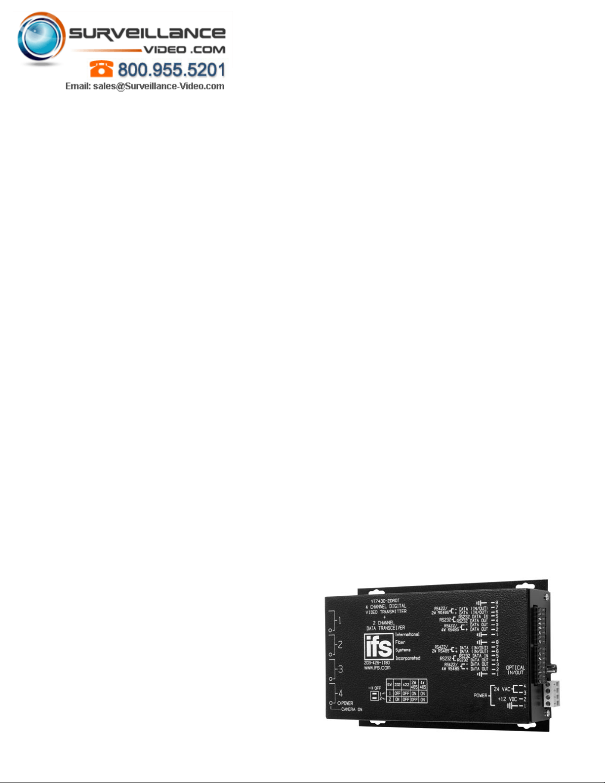
VT/VR7400-2DRDT Series
IFS 4-Channel Digitally Encoded Video
and 2 Bi-Directional Data Multiplexer
Overview
The IFS VT/VR7400-2DRDT video transmitter/data
transceiver and video receiver/data transceiver series
utilizes state-of-the-art 8-bit digital encoding and decoding for high-quality video transmission that exceeds the
requirements of EIA RS-250C for Medium-Haul Video
Transmission. These environmentally hardened units
provide transmission of four independent video channels
and two bi-directional data channels over one optical fiber
and are ideal for use in unconditioned roadside or
out-of-plant installations. Completely transparent to
and universally compatible with any NTSC, PAL, or
SECAM CCTV camera system. Data channels can be set
independently for RS-232, RS-422 and 2 or 4-wire RS-485
with tri-state support. Plug-and-play design ensures ease
of installation and no electrical or optical adjustments
are ever required. LED indicators are provided for rapidly
ascertaining equipment operating status, and these
units are available in either stand-alone or rack mount
Application Examples
• High Performance CCTV with PTZ Control
• High Performance CCTV with Access Control
4-Channel Digitally
Encoded Video
Standard Features
•
4 Real-Time Color Video Signals and 2 Bi-Directional
Data Signals on One Single Mode Optical Fiber
•
Tri-State Data Interfaces
•
Operating Parameters
•
Transmission: Extremely High Video Performance
•
Variation vs. Optical Path Loss
•
be a Problem
• Directly Compatible with All NTSC, PAL, or SECAM
CCTV Camera Systems
• Tested and Certified by an Independent Testing Laboratory
for Full Compliance with the Environmental Requirements
(Ambient Operating Temperature, Mechanical Shock,
Vibration, Humidity with Condensation, High-Line/LowLine Voltage Conditions and Transient Voltage Protection)
of NEMA TS-1/TS-2 and the Caltrans Specification for
Traffic Signal Control Equipment.
• Robust Design Ensures Extremely High Reliability In
Unconditioned Out-of-Plant Environments
• Solid-State Current Limiters on All Power Lines Provide
Unconditional Equipment Protection
• Comprehensive Lifetime Warranty
and 2 Bi-Directional
Data Multiplexer
Utilizes 8-bit digital encoding
and decoding for high-quality
video transmission.
Page 2
Specifications
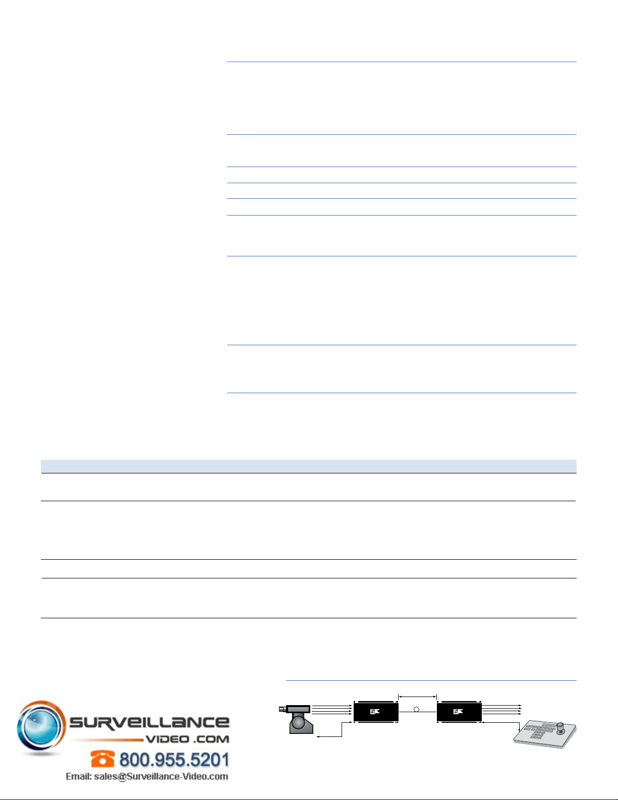
RS-232
up to 31 miles
(51 km)
1 Fiber
9/125�m SM
4 Video Inputs
(Coax)
VT7430DRDT VR7430DRDT
4 Video Outputs (Coax)
to monitors or switches
Control
Data
Control
Data
PTZ Control
Video
Video Input: 1 volt pk-pk (75 ohms)
Input/Ouput Channels: 4
Bandwidth: 10 Hz - 6.5 MHz per channel
Differential Gain: <2%
Differential Phase: <0.7°
Tilt: <1%
Signal-to-Noise Ratio (SNR): 60 dB @ Max. Optical Loss Budget
Data
Data Channel: 2
Data Format: RS-232, RS-422, 2-w or 4-w RS-485 with Tri-State, Manchester, Bi-phase
Wavelength 1310/1550 nm, Multimode or Single Mode
Optical emitter Laser Diode
Number of fibers 1
Connectors
Optical: ST, SC or FC (see ordering information)
Power: Terminal Block with Screw Clamps
Video: BNC (Gold Plated Center-Pin)
Electrical & Mechanical
Power: 12 VDC @ 500 mA (stand-alone)
Number of Rack Slots: 3
Current Protection: Automatic Resettable Solid-State Current Limiters
Circuit Board: Meets IPC Standard
Size (in./cm.) (LxWxH)
Surface Mount (Transmitter): 7.0 x 4.9 x 2.0 in., 17.8 x 12.5 x 5.1 cm
Surface Mount (Receiver): 7.0 x 4.9 x 3.0 in., 17.8 x 12.5 x 7.5 cm
Rack Mount: 7.7 x 5.0 x 3.0 in., 19.6 x 12.7 x 7.5 cm
Shipping Weight: < 2 lbs./0.9 kg
Environmental
MTBF: > 100,000 hours
Operating Temp: -40° C to +74° C
Storage Temp: -40° C to +85° C
Relative Humidity: 0% to 95% (non-condensing)†
†May be extended to condensation conditions by adding suffix ‘–C’ to model number for conformal coating.
Ordering Information
Part Number Optical Pwr. Budget Max. Distance*
Multimode
62.5/125µm**
Single Mode
9/125µm
Accessories
♦
Options
* Optical transmission distance is limited to optical loss of the fiber and any additional loss introduced by connectors, splices and patch panels.
Distance can also be limited by fiber bandwidth. ** For 50/125 Fiber, subtract 4 dB from Optical Power Budget.
*** This product may be used with 62.5 µm graded index multimode fiber having
a maximum run length of 2 km and/or a maximum optical loss budget of 10 dB.
♦
All accessories are third party manufactured.
VT7420-2DRDT
VR7420-2DRDT
VT7430-2DRDT
VR7430-2DRDT
VT7430-2DRDT-HP
VR7430-2DRDT-HP
PS-12VDC 12 Volt DC Plug-in Power Supply (Included)
PS-12VDC-230 12 Volt DC Plug-in Power Supply, 230 VAC Input (Included if specified at time of order)
Add ‘-R3’ to Model Number for R3 Rack Mount - No Charge (Requires R3 Rack purchased separately)
Add ‘-SC’ to model number for SC Optical Connector (For Single Mode equipment only)
Add ‘-C’ for Conformally Coated Printed Circuit Boards (Extra charge, consult factory)
Add ‘-HP’ to VT Model Number for 26 dB Single Mode Optical Power Budget
Add ‘-FC’ to model number for FC Optical Connector (For Single Mode equipment only)
Description
4 Channel Video Transmitter/Data Transceiver (1310/1550 nm)
4 Channel Video Receiver/Data Transceiver (1310/1550 nm)
4 Channel Video Transmitter/Data Transceiver (1310/1550 nm)
4 Channel Video Receiver/Data Transceiver (1310/1550 nm)
4 Channel Video Transmitter/Data Transceiver (1310/1550 nm)
4 Channel Video Receiver/Data Transceiver (1310/1550 nm)
Fibers Required
1
1
1
System Design
18 dB
17 dB
23 dB
1.2 miles (2 km)***
31 miles (51 km)
43 miles (69 km)
 Loading...