

Page 1

GE
Security
P/N 1069699 • REV 01.00 • ISS 16JUN10
DFR Card Cage Rack and
PS1 Power supply Unit
Installation Guide
Page 2

Copyright
© 2010 GE Security, Inc.
This document may not be copied in whole or in part or otherwise reproduced without prior
written consent from GE Security, Inc., except where specifically permitted under US and
international copyright law.
Disclaimer
The information in this document is subject to change without notice. GE Security, Inc.
(“GE Security”) assumes no responsibility for inaccuracies or omissions and specifically disclaims
any liabilities, losses, or risks, personal or otherwise, incurred as a consequence, directly or
indirectly, of the use or application of any of the contents of this document. For the latest
documentation, contact your local supplier or visit us online at www.gesecurity.com.
This publication may contain examples of screen captures and reports used in daily operations.
Examples may include fictitious names of individuals and companies. Any similarity to names
and addresses of actual businesses or persons is entirely coincidental.
Trademarks and patents
GE and the GE monogram are trademarks of General Electric Company.
Other trade names used in this document may be trademarks or registered trademarks of the
manufacturers or vendors of the respective products.
Intended use
Use this product only for the purpose it was designed for; refer to the data sheet and user
documentation for details. For the latest product information, contact your local supplier or visit
us online at www.gesecurity.com.
FCC compliance
This equipment has been tested and found to comply with the limits for a Class A digital device,
pursuant to part 15 of the FCC Rules. These limits are designed to provide reasonable protection
against harmful interference when the equipment is operated in a commercial environment.
This equipment generates, uses, and can radiate radio frequency energy and, if not installed
and used in accordance with the instruction manual, may cause harmful interference to radio
communications.
You are cautioned that any changes or modifications not expressly approved by the party
responsible for compliance could void the user's authority to operate the equipment.
Regulatory information
N4131
Manufacturer
GE Security, Inc.
HQ and regulatory responsibility:
GE Security, Inc., 8985 Town Center Parkway, Bradenton, FL 34202, USA
EU authorized manufacturing representative:
GE Security B.V., Kelvinstraat 7, 6003 DH Weert, The Netherlands
European Union directives
2002/96/EC (WEEE directive): Products marked with this symbol cannot be disposed of as
unsorted municipal waste in the European Union. For proper recycling, return this product to
your local supplier upon the purchase of equivalent new equipment, or dispose of it at
designated collection points. For more information see: www.recyclethis.info.
Contact information
For contact information see our Web site: www.gesecurity.com.
For contact information see our Web site: www.gesecurity.eu.
Page 3

DFR PS1 i
Content
Safety Instructions 1
Overview 2
Features 2
Model Numbers 4
Hardware 5
Front and Rear Panel 5
LED Indicators 6
Application Drawing 7
TROUBLESHOOTING 9
Specifications 10
Page 4

Page 5

DFR PS1 1
Safety Instructions
Please be familiar with all information in this manual prior to installation and
operation.
ALL ELECTRICAL INSTALLATIONS MUST MEET LOCAL AND NATIONAL WIRING
CODES AND SHOULD BE PERFORMED BY A QUALIFIED ELECTRICIAN.
1. Keep these instructions.
2. Heed all warnings.
3. Follow all instructions.
ENVIRONMENT
1. Do not use this apparatus near water.
2. Do not block any ventilation openings. Install in accordance with the
manufacturer's instructions.
3. To reduce the risk of fire or electric shock, do not expose this appliance to rain or
moisture.
4. Do not install near any heat sources such as radiators, heat registers, stoves, or
other apparatus (Including amplifiers) that produce heat.
5. The building installation is considered as providing Short-circuit backup protection
6. Unplug this apparatus during lightning storms or when unused for long periods of
time.
7. Apparatus shall not be exposed to dripping or splashing and no objects filled with
liquids, shall be placed on the apparatus.
CONNECTION TO AC OUTLET
The power supply should be operated only from a standard outlet with proper
grounding connection.
CAUTION! PLUG REPLACEMENT SHOULD BE DONE BY A QUALIFIED ELECTRICIAN.
PLEASE ENSURE PROPER POLARITY OF THE CONNECTIONS.
Do not use extension cord unless absolutely necessary. If an extension cord must be
used, make sure the extension cord wire size should be MINIMUM 12AWG, 20A.
FUSE REPLACEMENT
Ensure properly rated fuse (250V, 4A) is used in each of the module and should be
replaced with authorized device.
DIS-ASSEMBLY AND REPAIR
Only use attachments/accessories specified by the manufacturer.
The power supply should be disassembled or repaired by a qualified technician.
Incorrect reassemble or repair may result in a risk of electric shock of fire which may
result in personal injury and property damage.
WEEE statement: Please do not throw electronic device
Page 6

2 DFR PS1
Overview
The PS1 Internal Rack Power Supply is designed to provide power to a DFR Card Cage
Rack. The unit provides a single 12 VDC output. The power supply accepts an AC input
voltage from 100 to 240 VAC, 60/50 Hz. A second power supply can be installed in the
DFR Rack to provide redundancy.
Figure 1: DFR-PS1 product photo
Features
Alarm Features
An alarm is built into the PS1 power supply unit. The alarm activates a buzzer built
into the unit when the power supply is short circuit.
Front Panel Controls and Indicators
The PS1 front panel contains DC power and a RESET switch. The RESET switch is used
to disable the alarm and reset the PSU.
Power Supply Redundancy
The PS1 Internal Rack Power Supply is supplied with the DFR Card Cage Rack. If
power redundancy is required, a second PS1 can be installed in the card cage rack to
provide load sharing. If any unit fails, the remaining supply will take up the full load.
Standard Features
• 110 to 240 VAC, 60/50 Hz input
• 12 VDC output
• Supplied with Card Cage Rack
Page 7

DFR PS1 3
• PS1 can be provided as redundant supply for load sharing
• Power fail alarms if redundant supply installed
• Front panel indicator and MUTE switch
• AC power cord supplied
• Network management system for rack communications
o Status monitoring and operational management
o Operational level determination and access control
o Network ready for health and connection monitoring.
Page 8

4 DFR PS1
Model Numbers
Model Number Descriptions
DFR Rack chassis only
PS1 Power supply unit
Page 9

DFR PS1 5
Hardware
Front and Rear Panel
Figure 2: Front and Rear Panels for the DFR-PS1.
FRONT PANEL REAR PANEL
a Lock
b AC Outlet
c Fuse Holder
d Power switch
e Positioning pin
a b
c d
e
Page 10

6 DFR PS1
LED Indicators
Indicator Color Description
Green AC power applied and power supply operating normally.
Red Beyond the range of voltage and current limit.
POWER
OFF AC input failure.
Reset Button (RST)
a) Press this button shortly (less than 5 seconds) will make the internal alarm buzzer silent upon
recognition of the fault.
b) Press and hold the button for more than 5 seconds, the PSU will reset the unit to default setting and
resume supplying the load when the fault is cleared.
*PS1 can be controlled by NMS. For the details, please refer to the NMS User Guide.
Page 11
DFR PS1 7
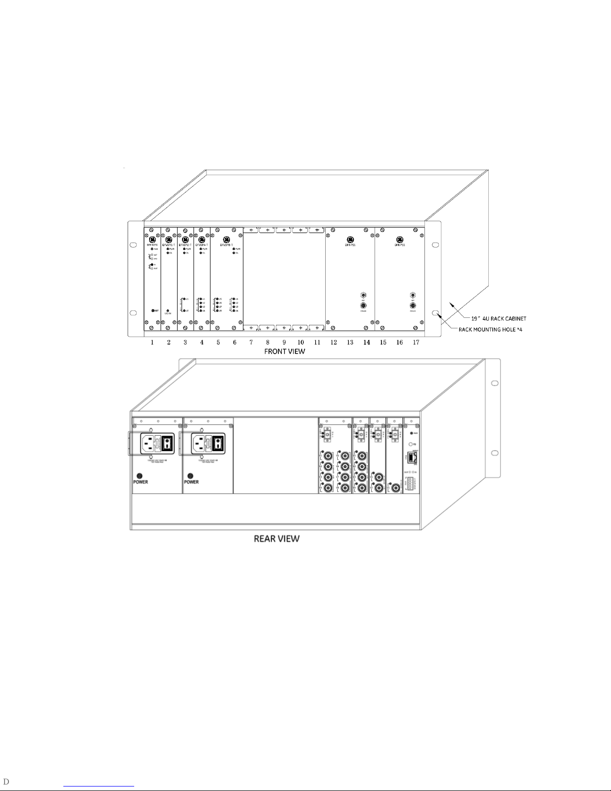
Application Drawing
Figure 3: Front and rear view of DFR (DFR, PS1 and DFV Series)
Page 12

8 DFR PS1
POWER SUPPLY
DFR is the standard 19” (483mm) 4RU chassis. The standard power supply unit for
DFR is PS1. The power supply can only be installed and operated with the DFR. The
power supply for delivering a constant 12VDC output from a wide range (100-240VAC
50-60Hz) of AC input voltages comprises with a transformer in combination with a
load sharing power supply circuit. The primary of the transformer is fused with a 4
amp slow-blow fuse at rear panel of the power supply unit.
A positioning pin is included on each PS1. The location of PS1 can only be installed in
slots 15-17 in the far right of the DFR as shown in the front view diagram above. The
secondary power supply unit PS1 for redundancy is optional. The location of
secondary power supply can only be installed at slot 12-14 in the DFR.
EARTH GROUND
Use 14AWG stranded wire attached to ground lug and earth ground.
Warning
UNDER NO CIRCUMSTANCES SHOULD THE MAINS EARTH BE DISCONNETED FROM THE
PS1 POWER SUPPLY UNIT
BACK PLANE
The back plane of the rack is for the purpose of distributing voltage to the plug-in
modules and communication with NETC and plug-in module. A 10-pin connector is
provided from the back plane for each module slot in the rack, supplying 12VDC and
data exchange by using RS485.
PLUG-IN MODULES
Plug-in modules can be installed into a DFR standard 19” (485mm) chassis with a
built-in power supply unit PS1 in a large system. Plug-in modules are installed by
sliding the module into a pair of top and bottom card guides in any available slot in
the rack. The module should be pushed in completely such that the 10-pin female
connector on the rear of the module engages the 10-pin male connector on the back
plane. The plug-in module is then fastened into place by tightening the captive panel
screw into the appropriate mating hole with a flat blade screwdriver.
Each plug-in module is equipped with a green LED, which will glow when power is
applied to the rack. It is impossible for the failure of any module to disable the entire
rack, since each input voltage line on the plug-in module is individually fused at 1
amp.
Page 13

DFR PS1 9
TROUBLESHOOTING
A. Should the power lamp on the power supply fail to light, insure that power to
the line cord is being supplied. If power is on the line cord, check and replace
the fuse in the fuse holder on the rear of the power supply. As a final measure,
the power supply should be replaced and returned.
B. Should the power LED on all individual plug-in modules fail to light, check the
following:
a. The power lamp on the power supply should be lit.
b. The 10-pin connector from the power supply should be firmly connected to
its mating connector on the back plane and located at slots 15-17 (The
optional secondary power supply should be located at slot 12-14).
c. All Plug-in modules should be firmly seated into their respective 10-pin
back plane mating connectors.
If the above conditions have been met, the rack should be replaced and returned.
C. Should the power LED on an individual plug-in fail to light, check the following:
a. The plug-in module should be firmly seated onto the 10-pin connector on
the back plane.
b. The fuses on the module should be intact. If not, return the module for
repair.
CAUTION! This product is designed for indoor use only. Do not attempt to
deploy the product for outdoor use. Damage to the product can result.
Page 14

10 DFR PS1
Specifications
Electrical
Power Supply Input 100 ~240 VAC, 50/60Hz
Input Current
1.66A@115VAC;
0.80A@230VAC
Supply Input Connector IEC C14 Chassis-mount socket
DC Voltage Output 12 VDC
Current Output 12.5A DC (max.)
Power Consumption 190VA@115VAC
Power Output 150W (max.)
Fuse Rating 4A, 250V, Slow-blow
Fuse Size 5x20mm, located in pull out tray on back panel
Connectors
Power input Recessed IEC 320 3-pin male (Cable supplied)
Mechanical
Height 158.4 mm
Width 75 mm
Depth 204.5 mm
Weight 1.57kg
Construction Aluminum
Finish Black semi-gloss paint
Mounting Four Captive screw
Environmental
Operating Temperature -20°C to +60°C
Operating Relative Humidity 20 to 90% non-condensing
Storage Temperature -40°C to +85°C
Storage Relative Humidity
10 to 95% non-condensing
MTBF
MTBF 100 Khrs min.
 Loading...