

Page 1
MVC-14S
Color Monitor
Page 2

© 2002 Kalatel, a GE Interlogix company
All Rights Reserved.
Any GE Interlogix, Kalatel division, software
supplied with GE Interlogix, Kalatel division,
products is proprietary and furnished under
license and can be used or copied only in
accordance with the terms of such license.
This document contains proprietary
information that is protected by copyright. No
part of this document may be reproduced or
transmitted in any form or by any means
without the prior written permission of GE
Interlogix, Kalatel division.
The information contained in this document is
subject to change without notice. GE
Interlogix, Kalatel division, in keeping pace
with technological advances, is a company of
product innovation. Therefore, it is difficult to
ensure that all information provided is entirely
accurate and up-to-date. GE Interlogix, Kalatel
division, accepts no responsibility for
inaccuracies or omissions and specifically
disclaims any liabilities, losses, or risks,
personal or otherwise, incurred as a
consequence, directly or indirectly, of the use
or application of any of the contents of this
document.
For the latest product specifications, visit GE
Interlogix, Kalatel division, online at
www.kalatel.com or contact your Kalatel sales
representative.
For technical support before and after installation, call 800-469-1676.
Technical support is available 24 hours a day, 7 days a week.
Call: Tech Support 800-469-1676 (6 A.M. – 5 P.M. PST Monday through Friday)
Tech Support 541-740-3589 (all other times)
Main 800-343-3358 or 541-754-9133
Fax: Tech Support 541-752-9096 (available 24 hours a day)
Main 541-754-7162
Web: www.kalatel.com
1036089A / November 2002
This equipment has been tested and
found to comply with the limits for a
Class B digital device, pursuant to part
15 of the FCC Rules. These limits are
designed to provide reasonable
protection against harmful interference
when the equipment is operated in a
commercial environment. This
equipment generates, uses, and can
radiate radio frequency energy and, if
not installed and used in accordance
with the instruction manual, may cause
harmful interference to radio
communications.
You are cautioned that any changes or
modifications not expressly approved
by the party responsible for compliance
could void the user's authority to
operate the equipment.
Page 3

MVC-14S User Manual Table of Contents
TABLE OF CONTENTS
BEFORE YOU BEGIN................................................................4
1 INSTALLATION ...................................................................5
RONT PANEL FUNCTION CONTROLS..................................8
2 F
2.1 USING THE FUNCTIONS MENU ....................................8
2.1.1 Setting a Monitor Title...................................................9
WARRANTY AND RETURN INFORMATION..................................13
ADVANCE REPLACEMENT POLICY .....................................13
1036089A / November 2002 3
Page 4

Before You Begin MVC-14S User Manual
BEFORE YOU BEGIN
Read these instructions before installing or operating this product.
Note: This installation should be made by a qualified service person and should conform to
local codes.
This manual provides installation and operation information. To use this
document, you must have the following minimum qualifications:
• A basic knowledge of CCTV systems and components
• A basic knowledge of electrical wiring and low-voltage electrical
hookups
Use this product only for the purpose for which it was designed.
Customer Support
For assistance in installing, operating, maintaining, and troubleshooting
this product, refer to this document and any other documentation
provided. If you still have questions, contact Kalatel Technical Support:
GE Interlogix, Kalatel division
Call: 800-469-1676
Fax: 541-752-9096
Note: You should be at the equipment, ready with details before calling Technical Support.
Conventions Used in this Manual
Boldface or button icons highlight command entries. The following
WARNING, CAUTION, and Note statements identify potential hazards:
* WARNING:
Improper use of this equipment can cause severe bodily injury or
equipment damage.
** CAUTION:
Improper use of this equipment can cause equipment damage.
Note: Notes contain important information about a product or procedure.
* This symbol indicates electrical warnings and cautions.
** This symbol indicates general warnings and cautions.
4 1036089A / November 2002
Page 5
MVC-14S User Manual Installation
1 INSTALLATION
CAUTION:
To prevent electric shock, do not remove the monitor cover. Qualified
service personnel should make repairs.
CAUTION:
Complete all installation steps before supplying power to the unit.
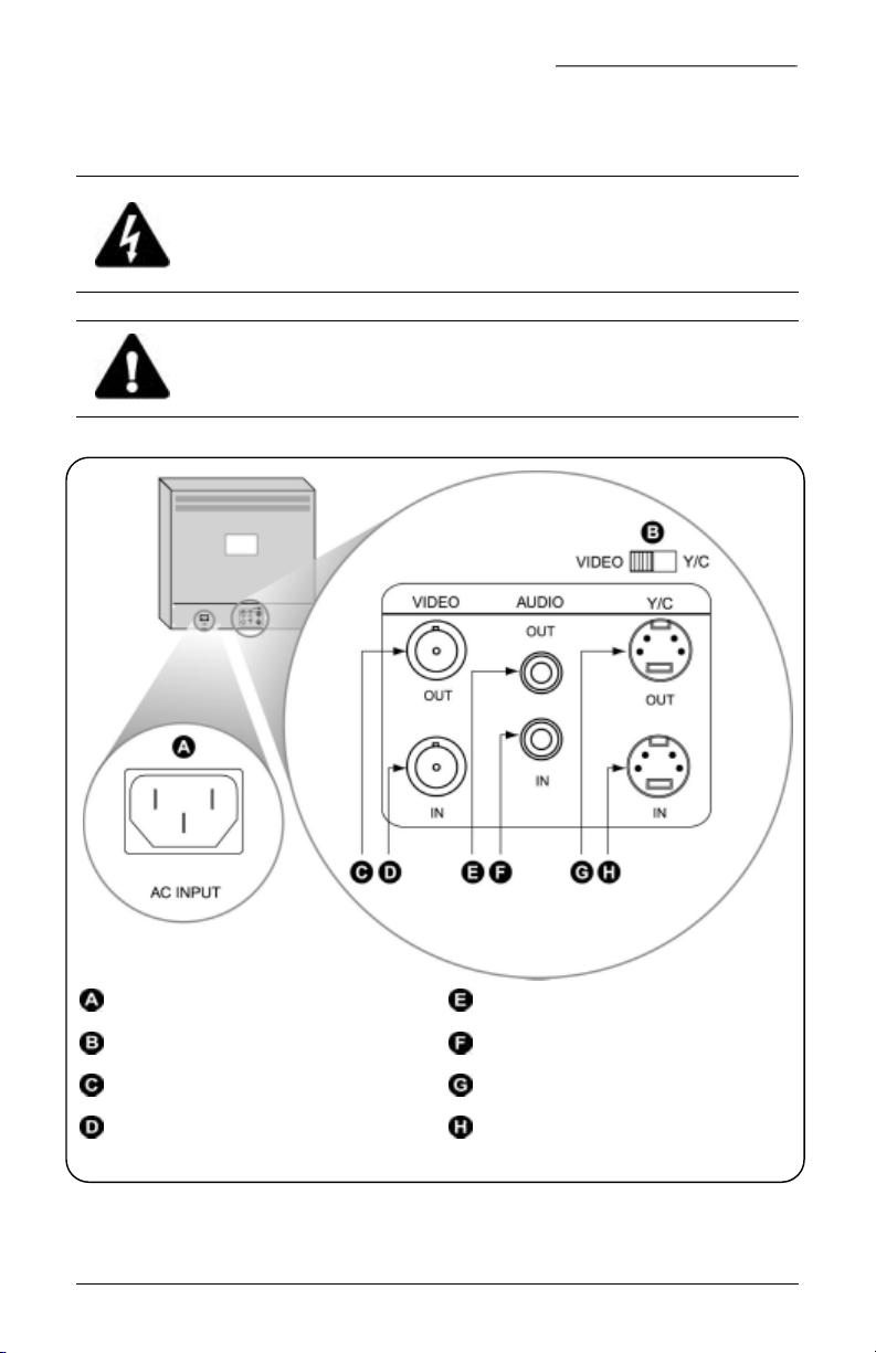
AC input connector Audio out connector (RCA)
Signal input switch (in video mode) Audio in connector (RCA)
Video out connector (BNC) Y/C out connector (4-pin mini-DIN)
Video in connector (BNC) Y/C in connector (4-pin mini-DIN)
Figure 1. Rear panel connections
See Figure 1 and perform the following:
1) Choose an appropriate location for installation.
1036089A / November 2002 5
Page 6

Installation MVC-14S User Manual
CAUTION:
To prevent the unit from overheating, keep it in a well-ventilated area and do
not place objects on the unit.
CAUTION:
To prevent fire and electric shock, do not expose the unit to moisture.
2) Set the signal input switch. For standard coaxial cable connection
set the switch to VIDEO. For Y/C cable connection set the switch to
Y/C.
NOTE: For steps 3-4 use either the Y/C or the VIDEO connections, whichever corresponds
with the selection made in step 2.
3) Attach the video in connector of the monitor to the video output
connector of the unit providing video.
4) If applicable, attach the previously installed monitor’s video out
connector to the video input connector of an additional unit as
shown in Figure 2.
NOTE: The MVC-14S monitor is auto-terminating.
Figure 2. Camera and two MVC-14S monitors
5) Attach the monitor’s power cord (provided) to the AC input
connector.
6) Insert the power plug into an approved power source.
Other connections:
• Connect the audio in connector to the audio output connector of a
VCR or other equipment.
6 1036089A / November 2002
Page 7

MVC-14S User Manual Installation
• Connect the audio out connector to the audio input connector of a
VCR or other equipment.
1036089A / November 2002 7
Page 8

Front Panel Function Controls MVC-14S User Manual
2 FRONT PANEL FUNCTION CONTROLS
To power up the unit press the power button and confirm that the green
power indicator light is on (Figure 3).
Power indicator Down/Brightness button
Power button Up/Contrast button
ENTER select button OSD (On Screen Display)
menu button
Figure 3. Front panel controls
+ Return to factory default settings
2.1 USING THE FUNCTIONS MENU
To access the functions menu see Figure 3 and perform the following
procedure.
NOTE: For quick access to the Brightness control screen press , for the Contrast control
screen press
1) Press OSD. The Functions Menu displays (Figure 4).
2) Press the down and up buttons to navigate between functions. The
active function is highlighted with a red bar.
8 1036089A / November 2002
.
Page 9

MVC-14S User Manual Front Panel Function Controls
Figure 4. Functions menu with COLOR function highlighted
3) Press ENTER to view the control screen for the highlighted
function.
4) Press the up and down buttons to make the desired adjustments to
the function. (See Setting a Monitor Title for detailed instructions on
the Title function.)
5) Press ENTER to save the adjustment and return to the functions
menu.
6) Press OSD to exit the functions menu and return to normal mode.
NOTE: Because the MVC-14S monitor is not multi-channel, the Dwell Time function is not
active.
NOTE: If you leave a function screen inactive for approximately 15 seconds, any
adjustments to that function will be lost and the monitor will default to the normal mode.
2.1.1 SETTING A MONITOR TITLE
The MVC-14S can display a monitor title containing up to eight
characters. The character options include complete upper- and lowercase alphabets as well as numeric and symbolic characters. Once
programmed, the title will display centered in the bottom of the monitor
screen.
1036089A / November 2002 9
Page 10

Front Panel Function Controls MVC-14S User Manual
To program an on-screen title for your monitor perform the following
steps.
1) Select Title from the functions menu. The Edit Title screen shown
in Figure 5 displays.
2) Confirm that CH A is highlighted with a red bar. Use the up and
down buttons to highlight it if necessary.
NOTE: Whether you use the MVC-14S in Video or Y/C mode, only the title labeled
CH A will display. Do not attempt to enter the CH B and Y/C titles: they will not
display because there is no built-in switcher in the MVC-14.
Figure 5. Title function screen with CH A highlighted
3) Press ENTER to activate the first character space. A purple box
highlights the active space.
4) Press the up and down buttons to navigate through the available
characters.
5) Press ENTER to select the desired character and move to the next
character space.
10 1036089A / November 2002
Page 11

MVC-14S User Manual Front Panel Function Controls
6) Repeat steps 3-5 until you have selected a title containing up to
eight characters.
7) Press OSD to navigate off the title.
8) Press the down arrow to navigate to either TITLE ON or TITLE
OFF, whichever is currently displayed on the screen.
a. If TITLE OFF is currently displayed, press the ENTER
button to select TITLE ON.
9) Press the down arrow to highlight EXIT.
10) Press ENTER to exit the Edit Title screen.
11) Press OSD to exit the function menu.
The title will display on the monitor screen. To edit the title repeat steps
1-11. To hide the title select TITLE OFF from the Edit Title screen.
1036089A / November 2002 11
Page 12

12 1036089A / November 2002
Page 13

MVC-14S User Manual Warranty and Return Information
WARRANTY AND RETURN INFORMATION
GE Interlogix, Kalatel division, warrants its equipment for three years
from the date of purchase. This warranty covers defects in materials and
workmanship only; equipment failures that are due to improper
installation, modification, abuse, or acts of nature are not covered by this
warranty. The repair department will evaluate all equipment returned for
repair to determine warranty coverage. The Tech Support Manager will
resolve any questions that may arise during evaluation to make a final
determination.
Note: The three-year warranty does not apply to the following products:
MobileView
purchase.
For all warranty repairs, GE Interlogix, Kalatel division, will cover all
costs, including parts, labor, and shipping. Repaired equipment will be
returned via the same method of shipment in which it was received. If a
customer requests a faster return shipment, the difference will be
charged.
For all non-warranty repairs, the customer will be billed for parts, labor,
and shipping. Labor will be billed in half-hour increments.
Note: Customers requesting an estimate prior to repair will be notified by phone. If they
cannot be reached, they will be notified by fax. If we are unable to reach the contact person
for repair authorization after one phone attempt and two fax attempts, the equipment will be
returned without being repaired. We will hold equipment no longer than two weeks.
®
and the monitor CRT, which carry a 12-month warranty from the date of
ADVANCE REPLACEMENT POLICY
When an advance replacement is required, we will send the customer
replacement equipment from our stock and receive the returned product
in exchange. The received equipment will be evaluated and the repair
department will determine whether it is a warranty replacement. If it is
non-warranty, see our repair policy above for details. The following
guidelines will be used for all advance replacements:
• Fewer than 45 days from purchase, GE Interlogix, Kalatel division,
will replace the product with new equipment.
• From 45 days to 1 year from purchase, GE Interlogix, Kalatel
division, will replace the product with refurbished equipment.
• From 1 year to 3 years from purchase, the product must be sent in
for repair. Advance replacements will be sent for a fee of $100.
If you have questions about this policy, please contact Kalatel’s RMA
department at 800-469-1676.
1036089A / November 2002 13
Page 14

 Loading...