

GE Security GEA-CE4-D36N-IP, GEA-CE3-D36P-IP, GEA-CE3-D36N-IP, GEA-C3-D36N-IP, GEA-C3-D36P-IP Quick User Guide
...Page 1

GE
Security
Legend
Quick Guide
g
Page 2
Introduction
Welcome to the Legend Quick Guide. This guide helps you install, program, and
use your Legend dome. It includes step-by-step instructions that show how to
perform basic system tasks. Please refer to the user manual for complete details,
when necessary.
Legend sets a new standard for integrated dome cameras. SilkTrak™ direct
drive technology eliminates roughness common to other domes, and easy-to-use
menus simplify the programming of presets, tours, macros, privacy masks, and
alarms.
Contents
Application diagram .......................................................................................................................... 2
W iring ....................................................................................................................................................... 3
Addressing and terminating ......................................................................................................... 4
Accessing and navigating .............................................................................................................. 5
Basic programming ............................................... 7
Advanced programming .....................................9
System defaults .................................................... 17
Troubleshooting .................................................... 18
TIP
You’ll find special items such as Tips
and Cautions in the page margins.
These items make setup and basic
operation easier.
TIP
If you have a problem installing,
programming, or operating your Legend
dome, try these solutions in this order:
1) Read the Quick Guide.
2) Read the corresponding sections of the
installation and user manuals.
3) Call Technical Support.
From 6 a.m. to 5 p.m. (Pacific Time),
Monday through Friday, excluding holidays:
Toll-free: 888.437.3287
in the US (including Alaska and Hawaii),
Puerto Rico, and Canada
Outside the toll-free area: 503.885.5700
Sales: info@gesecurity.com
Technical Support: generaltech@ge.com
Copyright © 2005, GE Security Inc.
All rights reserved.
1 | Introduction
Page 3
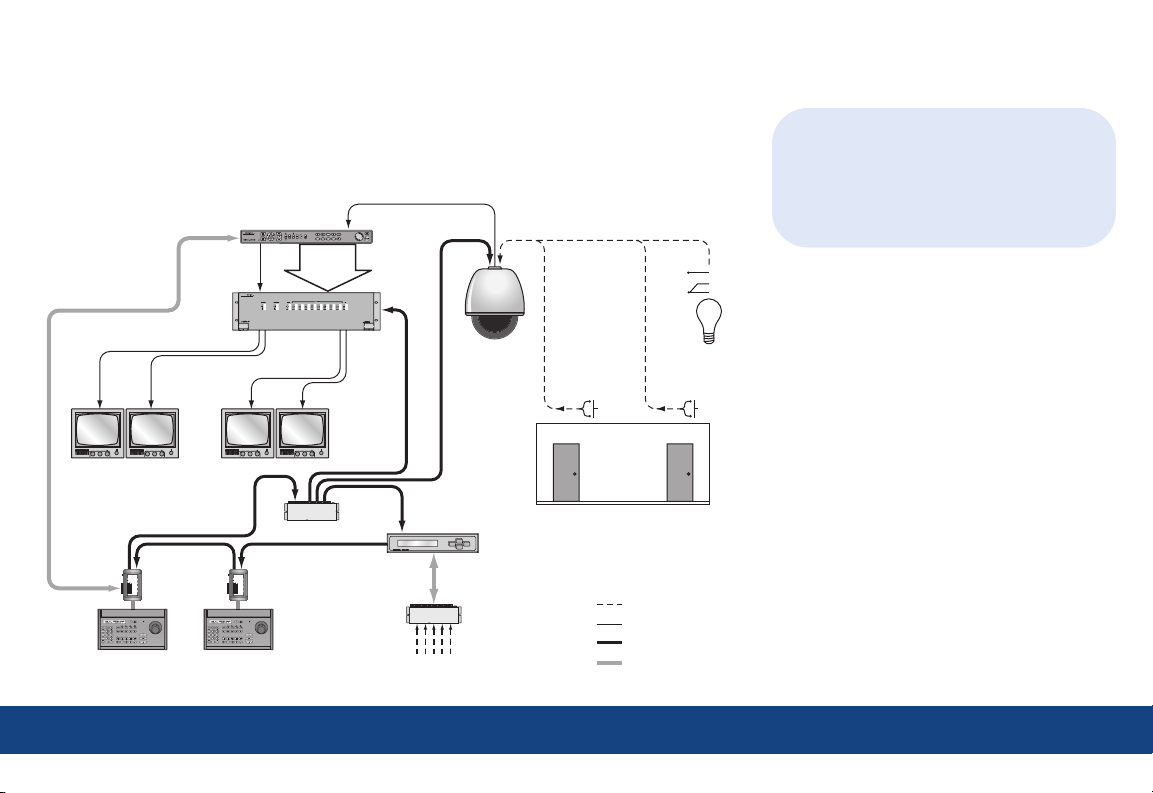
Application diagram
An advanced Legend system integrates alarms and relays. Each dome provides 8 alarm
inputs, 2 relay outputs, 127 presets, 16 ShadowTours (up to 20 minutes total), and 32 macros
(up to 16 steps each).
Digital recorder
Video
loop-
through
Mon 2 Mon 3 Mon 4
Mon 1
SWITCH
BIAS
REMOVABLE
TERMINAL STRIP
POWER
12 VDC
EARTH GROUND
A
RS485
B
A
RS422 IN
B
A
RS422 OUT
78910653214
78910653214
B
SPEAKER SHIELD
AUDIO KEYPAD RS485 RS485
+
SPEAKER
Controller
keypad
SWITCH
BIAS
REMOVABLE
TERMINAL STRIP
POWER
12 VDC
EARTH GROUND
A
RS485
B
A
RS422 IN
B
A
RS422 OUT
78910653214
78910653214
B
SPEAKER SHIELD
AUDIO KEYPAD RS485 RS485
+
SPEAKER
Controller
keypad
Matrix
switcher
Data distributor
Alarm input
Alarm chassis
module
Alarm inputs
Dome
Local alarm
inputs
(dry contacts)
1 8
Local relay
Alarms/relays
Video
RS-422 data
RS-485 data
N/O
COM
N/C
outputs
TIP
The Legend protocol is backward
compatible, so you can replace older
domes in an existing Digiplex system with
Legend domes. The hardware, however, is
not backward compatible.
2 | Application diagram
Page 4
U
U
1C
HEATER/BLOWER
HEATER/BLOWER
(1 of 2)
THERMOSTAT
POWER
~
~
-+
O/C
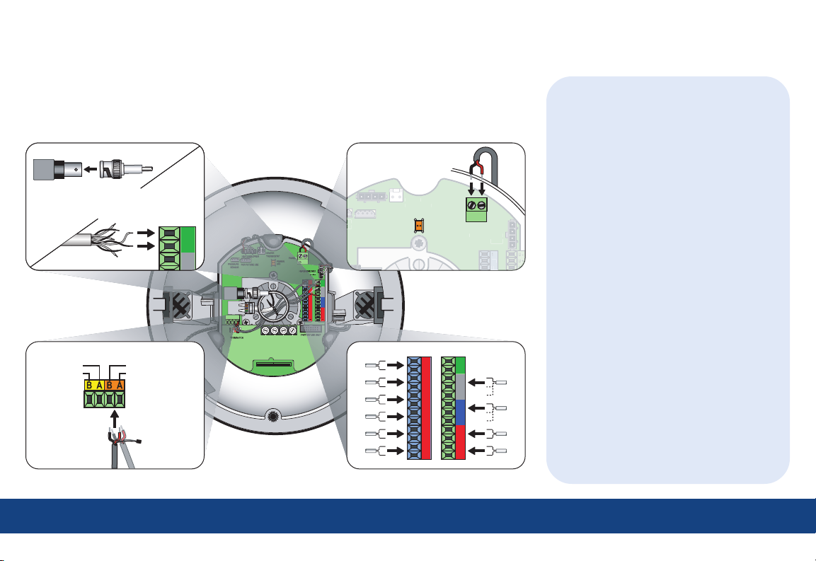
Wiring
For complete cabling requirements and installation instructions, see the installation manual.
All cables are connected to the housing board in the housing. Addressing, protocol, and
termination are set on the active housing board.
Video Power
Coaxial
— or —
AUX RS485+ MAIN RS485/422-AUX RS485--
Note: AUX is
for future use.
Data
UTP
MAIN RS485/422+
Note: Float
shield for
RS-485.
~
-+
O/C
COAXIAL
VIDEO
ETHERNET
DATA
D
E
F
0
1
2
ON
3
4
6
5
AUX
PROTOCOL
INTERCONNECT CARD
2
N/O
I/C
N/C
3
O/C
I/C
N/O
4
N/C
I/C
I/C
5
8
I/C
I/C
6
6
7
D
E
7
8
C
C
F
5
6
B
B
0
8
9
A
A
4
5
1
9
9
9
0
2
3
4
8
8
3
0
1
7
7
4
2
3
6
1
2
5
1's10's100's
--
1
I/C
+
O/C
2
I/C
N/O
N/C
3
I/C
O/C
N/O
4
I/C
N/C
I/C
5
I/C
8
I/C
6
I/C
7
Alarms/relays
TIPs
• For data, you have the choice of
connecting UTP for RS-422 or
connecting STP for RS-485.
- If you are installing RS-485,
float the shield at the dome and
ground it at the keypad.
- If you are daisy-chaining domes,
connect the incoming and outgoing
cables to the MAIN terminals.
• For video, you have the choice of
connecting UTP or coaxial.
- If you are installing coaxial video,
use only crimp-on BNC connectors.
• For power, feed the cable over the top
of the upper bracket, never through the
center. Power is not polarity sensitive.
• For alarms, use dry contacts.
• For relays, use a maximum operating
voltage of 30 VAC, 30 VDC at 0.5 A.
• Because of space constraints, if you are
installing more than five alarms and/or
relays, use a multiple-conductor cable
instead of individual single-pair cables.
• If heaters are present, route all cables
away from them.
3 | Wiring
Page 5
8
C
5C
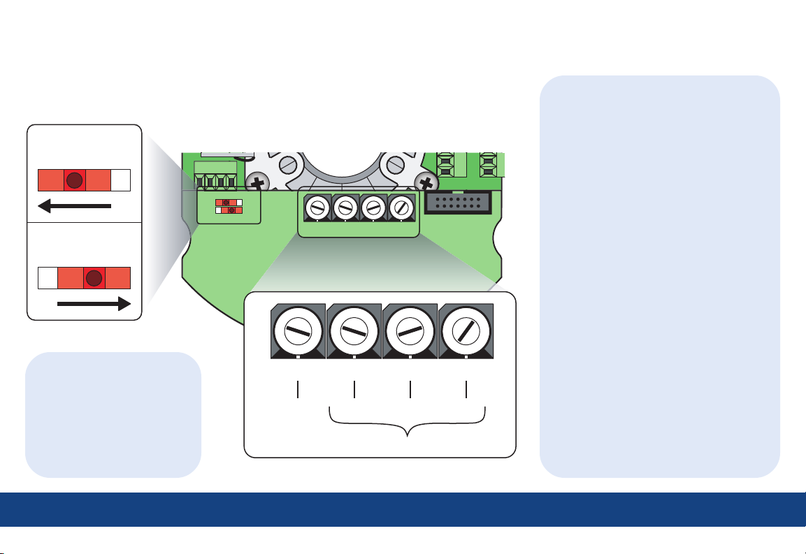
Addressing and terminating
The dome provides rotary switches for setting the camera’s site address and communication
protocol. Site addresses can be numbered from 0 to 1599. Termination is set with two slide switches.
MAIN
OFF
OFF ON
Note: AUX is for future use.
TIPs
AUX
ON
DATA
MAIN
--
Termination
OFF
AUX
AUX RS485+
MAIN RS485--
MAIN RS485+
ON
D
E
F
0
1
2
3
4
6
5
PROTOCOL
Rotary switches
D
E
C
F
B
0
INTERCONNECT CARD
3
4
6
5
A
9
8
7
1
2
PROTOCOL
6
6C
6
7
D
E
C
C
F
B
0
A
1
9
2
8
3
7
7
4
6
5
E
F
0
1
2
3
4
5
7
8
5
6
B
8
9
A
9
0
8
1
D
C
7
6
4
5
9
3
4
0
2
3
1
2
B
A
9
8
1's10's100's
9
0
1
7
8
3
2
FACTORY USE ONLY
7
6
8
5
9
4
0
1's10's100's
7
7
6
5
4
3
2
1
• Set termination to ON if the
dome or device is the final
receiver location.
• Set termination to OFF if the
data signal is looping out to
other domes or devices.
5 = ASCII 5 = 500 2 = 20 1 = 1
address = 521
TIPs
Equivalent values for the switches are:
• For the 1’s switch, the values increase
in increments of 1 from 0 to 9.
• For the 10’s switch, the values
increase in increments of 10 from 0
to 90.
• For the 100’s switch, the values
increase in increments of 100 from
0 to 900 for switch positions
0 through 9 and from 1,000 to 1,500
for positions A through F.
• For the PROTOCOL switch, the values
are as follows:
Switch Value
0 GE Digiplex (RS-422) @ 4800 baud
1 GE Impac (RS-485) @ 9600 baud
2 For future use
3 For future use
4 For future use
5 GE ASCII @ 9600 baud
6 Pelco D @ 2400 baud
7 Ultrak @ 9600 baud (even parity)
8 For factory use
9 For factory use
A For future use
B For future use
C For future use
D For future use
E For future use
F For future use
4 | Addressing and terminating
Page 6
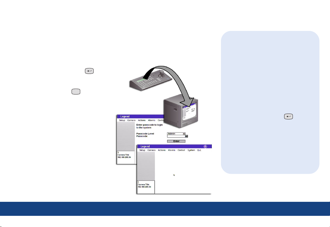
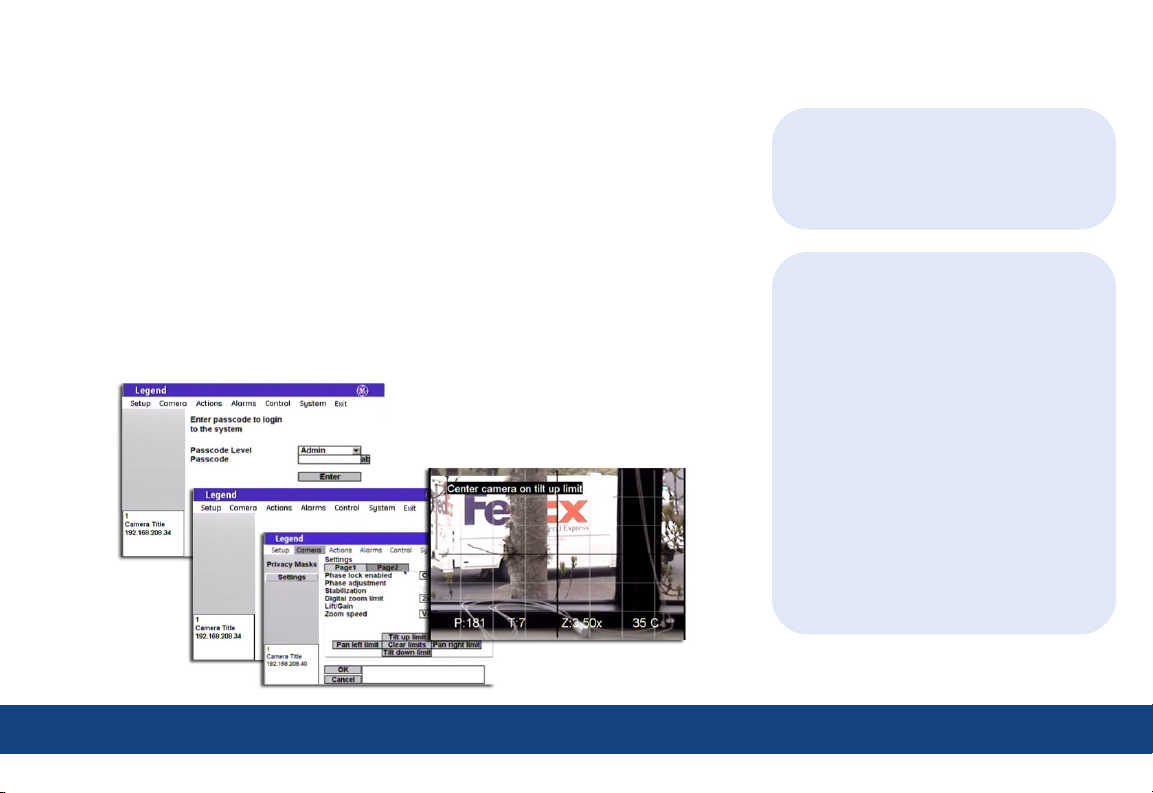
Accessing and navigating the menus
If passcodes were turned on during installation (or later), access to the menus of the graphical
programming interface will be passcode-protected. Otherwise, you will be taken directly to the
main menu. For details about passcodes, see the installation and user manuals.
Accessing the menus
1. Starting at the keypad (a GE KTD-405
keypad), press and hold the set ( ) key
until you hear a beep and the programming
code display appears on the keypad’s LCD.
2. Press the 9, 5, 1, and seq (
3. Press 3 on keypads of version 1.2.09 or later
to select CAMERA. If using a keypad of
version 1.1.06 or earlier, press 3 on the first
screen to select CAMERA/RCVR, then press 1
to select CYBERDOME on a second screen.
4. Enter the dome’s 4-digit camera site number
(fewer digits with older keypads). See TIPS.
The joystick now becomes a simulated
mouse and drives a cursor on the monitor
screen over the menus of the graphical
programming interface.
5. If passcodes are turned on, select your
passcode level and enter your passcode.
If passcodes are not turned on, you will be
taken directly to the main menu.
You can now access any programming
parameters allowed by your passcode.
seq
) keys.
TIPs
• The Legend protocol supports all of
the common commands of other
manufacturers’ keypads and protocols,
such as PelcoD, Ultrak, Impac/485, and
ASCII.
• To verify your keypad’s version, press
and hold the mon key until the keypad
beeps, then press the key.
• You can either enter the camera site
number with the preceding zeros (such
as 0003), or you can enter the camera
number without the preceding zeros
(such as 3) and press set ( ).
Note: Later keypad versions allow 4-digit camera
site numbers, while earlier keypad versions
allow 2- or 3-digit numbers.
• You can either enter passcodes by
pressing number keys on the keypad or
by opening the keyboard in the programming interface. Selecting the ab icon
opens the keyboard. Pressing the esc key
clears numbers entered from the keypad.
5 | Accessing and navigating the menus
Page 7

Navigating the menus
While in the menus of the programming interface, the joystick of your keypad operates in two
modes depending on what you are doing.
• While moving among the menus, the joystick is a simulated mouse and you enter commands
using the joystick.
• While controlling live video, the joystick is a video controller. When the joystick is a video
controller, you will use the keys of the keypad to enter commands.
Joystick as simulated mouse
To move the cursor (onscreen arrow) across
the menus:
Push or pull the
joystick in any
direction. The
farther you move
the joystick, the
faster the cursor
will move.
To make a selection:
Place the cursor
over a menu,
button,
checkbox,
item in a list,
or arrow of a
drop-down box,
and twist the
joystick.
knob on the
Note: You can also use the zoom +/- ( ) key.
zoom
+-
Joystick as video controller
To save (accept) live video programming::
iris
-
Press the iris+ (
+
) or the set ( )
key on the keypad.
To cancel (abort) live video programming::
Press the iris- (
iris
+
-
) or the esc (
esc
)
key on the keypad.
Using the onscreen keyboard
Open the keyboard by selecting the ab icon ( ). After you have entered the necessary characters,
select Done ( ) on the keyboard to return to the page and select OK ( ) to save the changes
TIPs
• The timeout of the keypad controls the
display of the programming interface.
The GE KTD-405 keypad times out after
five minutes of inactivity. The programming interface will therefore time out
after five minutes, as well, but the
system will sit on the enter camera
number display on the keypad’s LCD.
You have another five minutes within
which to reenter the camera number.
• For screens that have tabs, be aware
that the last tab accessed previously
will be the first tab accessed the next
time you enter a page.
made to the
page.
6 | Accessing and navigating the menus
Page 8

Basic programming
7 | Basic programming
Presets and ShadowTours are the most frequently used programmable features of domes. Use the
following procedures to program them quickly.
Presets
You can set presets from the keypad or with the menus. If you set presets from the keypad, you
may want to go into the menus to customize them with titles and exposure settings.
Programming presets from the keypad
1. Use the joystick to pan, tilt, and zoom the
camera to the desired view.
2. Press store (
store
) on the keypad.
3. Press the number keys on the keypad that
correspond to the preset number you want
to assign for this view.
4. Press store (
store
) again.
5. Optional: Verify your individual presets by
pressing f ind (
find
), then pressing the
number keys that correspond to a preset.
Note: You can reprogram any presets that you are
not satisfied with.
6. Optional: Go into the menus and customize
the preset with a title and exposure settings.
Command Keypad shortcut
Set a preset store | (number) | store
Set the left autopan limit store |
Set the right autopan limit store |
| store
| store
Programming presets with the menus
1. Access the menus (page 5).
2. Select:
a. Actions;
b. Presets;
c. Edit;
d. a preset
number;
e. and POS.
3. Use the joystick to pan, tilt, and zoom the
camera to the desired view.
iris
-
4. Press iris+ (
+
) or set ( ) to
save the preset position, or press iris-
iris
-
+
(
) or esc (
esc
) to cancel it.
5. After you have saved a preset position, you
can use the other options on the Edit, Display,
and Advanced tab pages to customize the
preset’s title, duration, and exposure settings.
TIPs
• There are 127 presets (1 through 127) for
each dome. If you are using presets 62
and 63 for the left and right autopan limits,
then you have a total of 125 presets.
• Most keypads have a limited number of
preset numbers they can call. If you are
using a 1.2.09 or later version of the GE
KTD-405 keypad, you can call up all 127
preset numbers directly from the keypad.
Earlier versions of the keypad can call
up only the first 63 preset numbers.
Note: To verify your keypad’s version, press and
hold the mon key until the keypad beeps,
then press the
key.
• If the keypad does not allow you to
program preset numbers 1 through 57
using the store key, you will need to
enable the lower preset numbers in the
keypad’s programming. Refer to the
keypad’s user manual.
• The dome provides the ability to remap
any preset or tour command coming in
from a keypad to activate any of the 127
presets, 16 tours, or 32 macro actions.
This enables you to manually initiate
any of the expanded capabilities of the
dome from keypad controllers with
limited command capability. Refer to the
user manual for details.
7 | Basic programming - presets
Page 9

ShadowTours
7 | Basic programming
You have a total of 16 ShadowTours (totaling 20 minutes) that you can define for each dome.
A ShadowTour is a tour that the camera learns (stores in memory) by recording your manual
operation of the camera. The tour can be replayed at any time.
To program a ShadowTour:
1. Access the menus (page 5).
2. Select:
a. Actions;
b. ShadowTours;
c. a ShadowTour
number; and
d. Program.
3. Press and release
iris+ (
) or
iris
-
+
set ( ) to start the ShadowTour timer.
4. Use the joystick to manually direct the camera through the desired PTZ movements.
5. Press iris+ (
esc
esc (
) to cancel it.
iris
-
+
) or set ( ) to save the ShadowTour, or press iris- (
iris
-
+
) or
6. After you have saved a ShadowTour, you can use the other options on the ShadowTour page to
customize the tour’s title.
7. Optional: Verify tours from the menu by selecting a tour number and selecting Show.
Note: If you are out of the menus, you can press tour (
desired tour.
tour
) and the tour number on the keypad to activate the
TIPs
• ShadowTour titles and other titles
appear on the monitor screen in default
positions. You can reposition any title
that has a Title POS button.
• When programming live video settings,
you need to save both the live video
settings and the changed settings on
the programming page.
- Save the live video settings by
iris
-
pressing iris+ (
+
) or
set ( ).
- Save the changes on the program-
ming page by selecting OK.
• The dome provides the ability to remap
any preset or tour command coming in
from a keypad to activate any of the
127 presets, 16 tours, or 32 macro
actions. This lets you manually initiate
any of the expanded capabilities of the
dome from keypad controllers with
limited command capability. Refer to
the user manual for details.
8 | Basic programming - ShadowTours
Page 10

Advanced programming
The Legend dome is ready to operate with its defaults, but it offers many features that can be
programmed to adapt to challenging lighting and performance conditions.
Menu tree
The menu tree guides you to the dome’s programmable features. Self-explanatory features have
been collapsed.
Setup Camera Actions Alarms Control System
Memory Privacy Masks Presets Summary Command Map Diagnostics
Memory
Passcode
Title/Date
Network
Preferences
Display
Language
Branding
Temperature
Coordinates
Pan
Tilt
Zoom
North
Privacy Masks
Settings
Page1
Day/Night
White balance
Exposure
Control
Autoslow
Lowest shutter
Return to auto
Page2
Phase lock
Phase adjustment
Stabilization
Digital zoom
Lift/Gain
Zoom speed
Tilt limits
Pan limits
Presets
ShadowTours
Macros
Areas
Summary
Contact Setup
Priority
Display
Relay State
Command Map
Power-on and
Resume
Speeds/Tracking
Max pan speed
Max tilt speed
Autopan speed
Proportional zoom
Zoom variable tilt
Electronic flip (E-flip)
Diagnostics
Temperature
Status
Logs
Firmware
Update
Under advanced programming:
• Menu tree on page 9.
• Cautions and performance requirements
on page 10.
• Common advanced procedures on
page 14.
Under cautions and performance
requirements:
• Cautions on page 10.
• Autopan limits on page 10.
• Pan and tilt coordinates on page 10.
• Privacy masks on page 11.
• The Exposure and Day/Night relationship
on page 11.
• Alarms on page 12.
• Command mapping on page 13.
Remember how to ...
• Access the menus? See page 5.
• Navigate the menus? See page 6.
9 | Advanced programming - menu tree
Page 11

Cautions and performance requirements
The information contained in this quick guide is condensed from the user manual. Please refer to
the user manual for complete details, when necessary.
Autopan limits
When setting autopan limits, be aware that
you must set both the right and left limit in
the same tilt hemisphere (positive or negative).
You can set them in either tilt hemisphere, but
you cannot cross hemispheres, meaning that
0°
(+90°)
you cannot pass the bottommost point or turn
the camera upside down. Allowing the camera
to E-flip will create an invalid set of autopan
Positive (+)
Positive (+)
hemisphere
hemisphere
limits that may cause unexpected camera
performance.
Pan and tilt coordinates
As shown, you can choose one of several coordinate systems to display the pan and tilt
coordinates of the camera on the monitor screen.
Pan coordinates Tilt coordinates
Choices: Bearings, Degrees 360°, and Degrees ±180° Choices: Degrees 180° and Degrees ±90°
Autopan limits
Legend
Legend
90°
(0°)
180°
(-90°)
Negative (-)
Negative (-)
hemisphere
hemisphere
CAUTION:
For all installations, heed these cautions:
• If you are using passcodes, record them
in a secure place. If you forget the
passcodes for a dome, you will need to
send the dome back to the factory so
that it can be reset with no passcodes.
• Clearing memory replaces your custom
settings with the factory default settings.
N, 0°, 0°
W, 270°, -90° E, 90°, +90°
S, 180°, +180°
10 | Advanced programming - cautions, autopan limits, and pan and tilt coordinates
NE, 45°, +45°NW, 315°, -45°
0°, +90° 180°, -90°
SE, 135°, +135°SW, 225°, -135°
N/270°/-90°
NE/225°/-135°NW/315°/-45°
135°, -45°45°, +45°
90°, 0°
Page 12

Privacy masks
When creating privacy masks, it is common
Make masks 50% larger than areas to be covered Make no masks directly below the dome
practice to make them at least 50% larger than
the areas that you wish to cover so that the
masked areas are properly covered. Also, be
Mask (50% larger)
Mask (50% larger)
aware that privacy masks cannot be created in
the area directly below the dome.
Area to be masked
Area to be masked
No masks allowed
No masks allowed
20° either side of 0° tilt
20° either side of 0° tilt
The Exposure and Day/Night relationship
Exposure is a camera feature that establishes what controls the light coming into the camera through the lens. Day/Night is a camera feature that
switches the camera mode from color (day) to monochrome (night) and removes the IR cut filter, which increases the camera’s sensitivity in low light.
It also allows the camera to function with IR lighting.
The Day/Night feature works only if the Control option of the Exposure feature is set to Auto. Two conditions can prevent the camera from switching
between the color and monochrome modes according to the Day/Night setting. One, if you’ve overridden the Auto setting of Exposure | Control with
manual commands from the keypad. Two, if you’ve called a preset (or a command containing a preset) that is programmed to override the Auto setting
of Exposure | Control.
In the second scenario, the camera returns to the Auto setting of Exposure | Control after you leave the preset. In the first scenario, you must issue a
command to return to the Auto setting of Exposure | Control. Using the iris key on the keypad manually adjusts the camera’s iris setting or shutter
speed, overriding the Auto setting of Exposure | Control. You must issue a pan or tilt command from the keypad to leave the manual override and return
to the Auto setting of Exposure | Control. While you remain in the manual override, the color and monochrome modes of the Day/Night setting will not
switch according to the changes in the lighting conditions. See the user manual for details.
11 | Advanced programming - privacy masks and the Exposure and Day/Night relationship
Page 13

Alarms
You can program up to eight alarm inputs and
two relay outputs per dome. Each alarm input
can call up (display) any preset, macro
(programmed routine), or ShadowTour. Legend
domes do not handle alarms in the same way
as most other alarm equipment. You need to be
aware of the key differences. See the user
manual for complete details.
Key differences of dome alarms
• Each dome alarm can include one dome action
(not required) and one or two relay actions.
• The Resume feature is disabled by alarms.
• Dome alarms are not acknowledged.
• When a dome alarm is set to a preset, tour,
or macro, the camera will stay with that action
until the operator issues a command from the
keypad. Resume will then be reenabled.
• Dome alarms are prioritized.
• Dome alarms are not held in a queue. Only
the highest priority alarm that is triggered
is actioned.
• If several dome alarms are triggered at the
same time, the next highest priority alarm is
actioned only if it is still being triggered after
the higher priority alarm has finished.
• If a higher priority alarm is triggered while a
lower priority alarm is being actioned, the
higher priority alarm will override the lower
priority alarm. The lower priority alarm will
be restarted only if it is still being triggered
after the higher priority alarm has finished.
• The only relay states that you need to clear
are those that are set to Infinite duration.
• Clear Infinite duration relay states by:
(1) selecting a Relay Off button; (2) using
another alarm command that sets the relay
with a duration of at least one second; or
(3) using a remapped preset command that
activates a macro.
• You can make a relay action a default action
upon the power-up of the dome by selecting
the Relay 1 on or the Relay 2 on button on
the Relay State screen.
TIP
When changing settings on any programming page, you need to confirm the new
settings by selecting OK on that page.
To program an alarm:
1. Access the menus (page 5).
2. Select Alarms and Contact Setup.
3. Select a contact number.
4. Select a contact type.
5. Optional: Give the alarm a name.
6. Optional: Assign an alarm action.
7. Select an action number, if an action was
assigned.
8. Optional: Add one or two relay actions.
9. Select relay durations, if relays were added.
10. Complete steps 3 through 9 for additional
alarms.
11. Select Priority and arrange the priority of
the alarms from the highest to the lowest.
12 | Advanced programming - alarms
Page 14

Command mapping
The dome provides the ability to remap any preset or tour command coming in from a keypad to
activate any of the 127 presets, 16 tours, or 32 macro actions. This enables you to manually initiate
any of the expanded capabilities of the dome from keypad controllers with limited capability.
Command mapping does not affect any of the internal command operations the dome performs,
such as resume and alarm actions. It only affects the actions the dome will perform when it
receives a command from an external device (keypad or alarm interface).
An example of remapping is using a preset command from the keypad (for example, Preset 7) to
run a macro (for example, Macro 1). In the command map programming, you would select the
command you wish to use (in this case, Preset 7) and remap that command to activate an assigned
action (in this case, Macro 1). See the user manual for complete details.
To remap a preset or tour number to activate another action:
1. Access the menus (page 5).
2. Select Control.
3. Select Command Map.
4. Under Command, select a command group
(preset or tour) to remap. (Preset, in the
example.)
5. Under Auxiliary input, select a number (for
example, 7) from that group to remap.
6. Under Assigned action, select an action
group (preset, tour, or macro) to assign to
that command number. (Macro, in the
example.)
7. Under Auxiliary input, select a number (for
example, 1) from that assigned action group
to assign to that command number.
8. Select Update. You have now remapped the
command (Preset 7) to activate the assigned
action (Macro 1).
9. Complete steps 4 through 8 for additional
commands.
TIPs
• When changing settings on any
programming page, you need to
confirm the new settings by selecting
OK on that page.
• Most keypads have a limited number of
preset numbers they can call, which will
limit how many commands can be
remapped. If you are using a v1.2.09 or
later version of the GE KTD-405 keypad,
you can call up all 127 preset numbers
directly from the keypad. Earlier
versions of the keypad can call up only
the first 63 preset numbers.
Note: To verify your keypad’s version, press and
hold the mon key until the keypad beeps,
then press the key.
13 | Advanced programming - command mapping
Page 15

Common advanced procedures
The information contained in this quick guide is condensed from the user manual. Please refer to
the user manual for complete details, when necessary.
Moving titles
Most titles are defaulted to align down the center of the screen and across the bottom. See
System defaults on page 17. You can, however, move titles to wherever you want them.
To move titles:
1. Select Title POS on the programming page of the title that you want to reposition.
2. Move the joystick to move the title to the desired position.
iris
-
3. Press iris+ (
esc (
+
esc
) to cancel it.
) or set ( ) to save the new position, or press iris- (
Programming actions in live video
Most actions in live video are programmed the same. Where they are programmed differently,
instructions will appear on the live video screen.
To program most actions:
1. Select Set north, Program, POS, or Set, depending on what you are programming.
2. At the live video screen, use the joystick to move the camera to the desired position or to
increase/decrease values on a scale.
iris
-
3. Press iris+ (
esc (
+
esc
) to cancel it.
) or set ( ) to save the new setting, or press iris- (
iris
-
+
+
) or
iris
-
) or
Under common advanced procedures:
• Moving titles on page 14.
• Programming actions in live video on
page 14.
• Building a macro on page 15.
• Resetting the dome on page 16.
• Rebooting the dome on page 16.
TIPs
• When changing settings on any
programming page, you need to
confirm the new settings by selecting
OK on that page.
• When establishing live video settings,
you need to save both the live video
settings and the changed settings on
the programming page.
- Save the live video settings by
iris
-
pressing iris+ (
+
) or
set ( ).
- Save the changes on the program-
ming page by selecting OK.
14 | Advanced programming - moving titles and programming actions in live video
Page 16

Building a macro
Macros are programmed routines. You can program up to 32 macros per dome and each macro can
contain up to 16 steps.
To program a macro:
1. Access the menus (page 5).
2. Select Actions, Macros, and the Program tab.
3. Select a macro number.
4. Macros have no steps initially. You can add
and program steps one at a time or you can
add up to 16 steps and go back to program
them. Select the Append button to add steps.
Note: Select a step and select the Remove button to
remove individual steps that you do not want.
5. Select a step number that you want to program or reprogram.
6. Select an action for the selected step using the options in the Type drop-down box. The step
type selected determines what additional options are available.
7. Select the specific number for the selected action. For example, preset number 14.
8. If you selected a jump as the action for the step, also select how many times you want the
jump step to repeat.
9. If you selected a preset or tour as the action for the step, also select: first , the speed for how
fast the camera will move to that preset or tour, and second, the transition of the video on the
monitor screen (freeze or zoom out) while the camera moves to that preset or tour. See TIPs.
10. If you selected a preset or relay as the action for the step, also select the duration for how
long the action for the step continues.
11. If you selected a relay as the action for the step, also select whether the relay is to be set to its energized state (check box checked) or not . See TIPs.
12. Complete steps 4 through 11 for additional steps in the macro.
13. Complete steps 3 through 11 for additional macros.
TIPs
• When changing settings on any program-
ming page, you need to confirm the new
settings by selecting OK on that page.
• The macro list shows the defined steps
for the macro in sequential order.
• The Append button adds one step to the
bottom of a macro’s list of steps.
• The Remove button deletes the currently
selected step from the macro.
• The Move up and Move down buttons
move the currently selected step up or
down one step in the macro list each
time they are selected.
• The Freeze option freezes the last image
on the monitor screen while the camera
is moving.
• The Zoom out option zooms the camera
out before it moves, remains zoomed out
while the camera is moving, and
reestablishes the zoom setting when the
camera arrives at its destination.
• Energized relay states are closed for
normally open connections and open for
normally closed connections.
15 | Advanced programming - building a macro
Page 17

Resetting the dome
You can reset the dome whether or not you have valid communication
between the keypad and the dome.
To reset the dome, cycle the power to the dome by turning the power
off then on.
o
I
Rebooting the dome
If you are using a GE KTD-405 keypad, and have valid communication between the keypad and the
dome, then you can easily reboot when necessary.
Note: You cannot currently reboot Legend domes from other keypads.
To reboot a dome, do the following from a KTD-405 keypad:
1. At the normal display (CAMERA #/MONITOR #), press and hold set ( ) until you hear a beep
and the programming code display appears on the keypad’s LCD.
2. At the ENTER PROGRAMMING CODE: display, enter the reset access code by pressing 1, 4, 7, 6,
and seq.
iris
-
3. At the RESET TO DEFAULTS? display, press iris+ (
+
) to select YES.
4. At the reset which display (ALL BUT TITLES, ALL, or CAMERA), press 3 to select CAMERA.
iris
-
5. At the RESET CAMERA #? ARE YOU SURE? display, press iris+ (
+
) to select YES.
The camera reboots in about 60 seconds. You will see the RESETTING CAMERA # display on
the keypad LCD, and the splash screen and color bars on the monitor screen, as the camera
reinitializes itself.
TIPs
Resetting or rebooting a dome does not
change or clear any programmed settings.
If you want to clear any programmed
settings, you need to clear the memory
via the options on the Memory screen
under Setup.
16 | Advanced programming - resetting and rebooting
Page 18

System defaults
Programming settings Default
Alarm box content ......................... All status
Alarm box duration ...................... During action
Alarm contact type ....................... N/O
Autopan speed ................................ Slow
Autoslow shutter ............................ Off
Backlight compensation ............ Off
Block color ........................................ Black
Block transparency ...................... No color
Branding ............................................. Off
Contact type (alarms) .................. N/O
Day/Night .......................................... Automatic
Digital zoom limit ......................... 12x
Electronic image flip (E-flip) .... On
Exposure control ........................... Iris
Gain....................................................... 0
Language ........................................... English
Lift .......................................................... 0
Night mode ....................................... Off
IP address ......................................... 192.168.208.250
Note: The 250 is the default site number (camera
address) for all domes.
Pan coordinates ............................. Degrees 360
Pan limits ........................................... Off
Passcodes ......................................... Off (blank)
Phase adjustment ......................... 50°
Phase lock enabled ..................... Off
System defaults
Programming settings Default
Power-on ........................................... Off
Preset title duration ..................... Inf inite
Privacy mask color ....................... Gray
Relay 1/Relay 2 ............................. No action
Relay duration ................................ Infinite
Resume ............................................... Off
Resume delay ................................. Off
Resume operation ........................ Preset
Return-to-auto................................. On
Subnet mask .................................... 255.255.255.0
Temperature display .................. Off
Temperature display
duration .......................................... During action
Temperature thresholds
(high and low) .............................. 0
Tilt coordinates .............................. Degrees 180
Tilt limits ............................................ Off
Title font color ................................. White
Title font weight ............................. Bold
Title font size ................................... 26 pt
Title length ........................................ 60 characters
White balance................................. Auto
Zoom coordinates ......................... Power
Zoom proportional ....................... On
Zoom speed ..................................... Variable
Zoom variable tilt ......................... On
System defaults
Default title positions
Compilation of titles on a monitor screen
17 | System defaults
Page 19

Troubleshooting
Following are the most common troubleshooting issues and their solutions.
I forgot my passcode.
If you forget the passcodes for a dome, you will
need to send the dome back to the factory so
that it can be reset with no passcodes.
I can’t get the programming interface to open.
Contact Technical Support. See page 2.
I can’t get the programming interface to
respond.
• First , reboot the dome with the keypad. See
Rebooting the dome on page 16.
• If that doesn’t work, then reset (cycle) the
power to the dome by turning the power off
then on. See Resetting the dome on page 16.
I can’t get the programming interface to close.
Reset (cycle) the power to the dome by turning
the power off then on. See Resetting the dome
on page 16.
Index
access codes .................................................... 5
actions .................................................................. 14
addressing ......................................................... 4
alarms .................................................................. 12
application diagram ..................................... 2
autopan limits .................................................. 10
backward compatibility .............................. 2
cancel/save ....................................................... 6, 8
cautions ............................................................... 10
command mapping ....................................... 13
coordinates (pan and tilt) ........................... 1 0
default settings ................................................ 17
exposure relationships ............................... 11
joystick operation .......................................... 6
keypad limitations......................................... 7, 13
live video ............................................................ 1 4
macros ................................................................. 1 5
menu tree ........................................................... 9
navigation .......................................................... 6
performance requirements ...................... 1 0
Index
presets ................................................................. 7
privacy masks .................................................. 11
protocols supported ..................................... 4, 5
rebooting the dome ...................................... 16
resetting the dome ........................................ 16
save/cancel ....................................................... 6, 8
selecting options ............................................ 6
STP (RS-485) ....................................................... 3
termination ........................................................ 4
timeout ................................................................. 6
titles ....................................................................... 14
tours (ShadowTours) ..................................... 8
troubleshooting ............................................... 1 8
UTP (RS-422) ...................................................... 3
wiring .................................................................... 3
18 | Troubleshooting
 Loading...