

GE Security FireShield FS302, FireShield FS502, FireShield FS1004 Technical Reference Manual
Page 1

FireShield
Technical Reference Manual
P/N 3100353 • Rev 3.0 • 12MAY03
Page 2

DEVELOPED BY
Phone: (941) 739-4200
Copyright © 2002
IMPORTANT INFORMATION
Limitation of liability
This product has been designed to meet the requirements of
the standards listed in “Compliance statement” below.
Installation in accordance with this manual, applicable
codes, and the instructions of the Authority Having
Jurisdiction is mandatory. The manufacturer shall not under
any circumstances be liable for any incidental or
consequential damages arising from loss of property or other
damages or losses owing to the failure of products beyond
the cost of repair or replacement of any defective products.
The manufacturer reserves the right to make product
improvements and change product specifications at any
time.
While every precaution has been taken during the
preparation of this manual to ensure the accuracy of its
contents, the manufacturer assumes no responsibility for
errors or omissions.
FCC warning
This equipment can generate and radiate radio frequency
energy. If this equipment is not installed in accordance with
this manual, it may cause interference to radio
communications. This equipment has been tested and found
to comply within the limits for Class A digital devices
pursuant to Subpart B of Part 15 of the FCC Rules. These
rules are designed to provide reasonable protection against
such interference when this equipment is operated in a
commercial environment. Operation of this equipment is
likely to cause interference, in which case the user, at his
own expense, will be required to take whatever measures
may be required to correct the interference.
Compliance statement
FireShield, when properly installed, operates as a Local
Protected Premises Fire Alarm System in accordance with
the following standards:
• NFPA Standard 72, 1999 Edition
• NFPA 70 National Electrical Code
• Underwriters Laboratories Standard 864, 8th Edition
• Underwriters Laboratories of Canada Standard ULC
S527-99
• Canadian Electrical Code Part I
• Standard for Installation of Fire Alarm Systems
ULC S524
• Standard for the Inspection and Testing of Fire Alarm
Systems ULC S536
FireShield also complies with Local Protective Signaling
(type L) - manual (M), automatic (A), waterflow (WF), and
sprinkler supervisory (SS) for:
• Coded (C) and non-coded signaling (NC)
• Remote Station (type RS) - with RPM or FSDACT
• Auxiliary (type A) - with CTM4.7 (this may include Local
with Shunt type connection to Master Box - type LS)
• Central Station (Type CS) - with FSDACT
–2003
Content
Chapter 1 System overview and operation • 1.1
System overview • 1.1
Operations overview • 1.1
Controls and indicators • 1.1
Component descriptions • 1.3
Operating the panel • 1.4
FSDACT LCD messages • 1.7
Chapter 2 Installation • 2.1
Installation checklist • 2.1
Installing the cabinet • 2.1
Installing the Remote System Indicator • 2.2
Installing the Remote Zone Indicator • 2.3
Installing the Remote Relay Module • 2.5
Installing the Power Expander Transformer • 2.7
Installing the FSDACT • 2.8
Connecting an RPM module • 2.10
Connecting a CTM module • 2.11
Connecting an auxiliary power supply • 2.12
Installing the terminal shield • 2.12
Chapter 3 Programming • 3.1
Overview • 3.1
Using the factory default settings • 3.2
Using an FSDACT • 3.2
Custom programming the panel • 3.2
FSDACT programming • 3.8
Chapter 4 Maintenance • 4.1
Preventive maintenance • 4.1
Appendix A Calculations • A.1
Battery calculation worksheet • A.1
Notification appliance voltage drop
calculation • A.3
Notification appliance circuit maximum wire
length calculation • A.4
Appendix B Programming templates • B.1
Panel programming worksheet • B.1
FSDACT programming worksheet • B.2
Appendix C Jumper settings and wiring diagrams • C.1
Appendix D Panel specifications • D.1
Appendix E Default event codes • E.1
Default Contact ID event codes • E.1
Default (4/2) event codes • E.2
Z Index • Z.1
FireShield Fire Alarm Control Panel Operating
Instructions • 1
Page 3

Chapter 1
System overview and operation
System overview
FireShield is available in three models: three-zone, five-zone,
and ten-zone. Each model is similar except for the number of
initiating device circuits (IDCs) and notification appliance
circuits (NACs), as shown in the following table.
Model IDCs NACs
FS302 (three-zone) 3 2
FS502 (five-zone) 5 2
FS1004 (ten-zone) 10 4
Model numbers may have the following suffixes: G or R
indicates gray or red enclosure, GD or RD indicates panel with
FSDACT, GC indicates ULC panel with terminal shield, GF
indicates a French ULC panel with terminal shield, and G-2
indicates 230 Vac input.
Each panel is configured for Class B operation. All models
except for the three-zone can be easily converted to Class A
by using two Class B circuits to make one Class A circuit.
If the optional FSDACT is installed, the panel:
• Sends a record of the event to the FSDACT LCD and to
the history log
• Uses the FSDACT to transmit event messages to a
monitoring station as programmed
Controls and indicators
REMOTE
DISCON-
1
2
3
4
LAMP TEST
NECT
WALK
TEST
RESET
SIGNAL
SILENCE
& DRILL
PANE L
SILENCE
DISABLE
DISABLE
DISABLE
DISABLE
DISABLE
ALARM
BATT
ANNUN
TROUBLE
TROUBL E
ALARM TROUBL E SUP/MON
1
2
3
NAC 1
NAC 2
SUPTROUBLE POWER DISAB LE
SIGNAL
WALK
GND
FAULT
TEST
SILENC ED
6
5
FireShield has the following optional components:
• Remote System Indicator (FSRSI)
• Remote Zone Indicator (FSRZI-A)
• Remote Relay Module (FSRRM)
• Power Expander Transformer (XTR3A120, XTR3A230)
(ten-zone only)
• DACT (Dialer)/Modem (FSDACT)
• City Tie Module (CTM4.7)
• Reverse Polarity Module (RPM)
• Battery Cabinet (BC-2)
Refer to Chapter 2 “Installation” for optional module details.
Operations overview
The panel operates in normal mode in the absence of any
alarm, supervisory, trouble, or monitor events. In normal
mode, the control panel monitors the system.
The panel operates in off-normal mode any time an event is
introduced into the system. When this happens, the panel:
• Changes contact positions on appropriate common relays
• Activates alarm outputs (for alarm events only)
• Turns on the appropriate LEDs and the panel buzzer
• Executes the appropriate programmed output response for
the input that signaled the event
• Communicates event information to appropriate optional
components (FSRSI, FSRZI-A, CTM4.7, or RPM)
Front panel display
(1) Lamp test
Buttons Description
REMOTE
DISCON-
NECT
Press the Remote Disconnect and Walk Test
buttons simultaneously to initiate a panel
lamp test. This lets you verify proper
operation of the LEDs on the panel and the
WAL K
TEST
remote annunciators.
(2) Control buttons
Button Description
REMOTE
DISCON-
NECT
Operating mode with FSDACT: Disables or
enables FSDACT. Has no effect on alarm
relay.
Operating mode without FSDACT: Disables
or enables the common alarm relay.
Programming mode: Selects the next option.
WAL K
TEST
Operating mode: Places the panel in walk
test mode. The Walk Test LED is on when
the panel is in walk test mode.
Programming mode: Selects the previous
option.
FireShield Technical Reference Manual 1.1
Page 4

System overview and operation
Operating mode: Initiates a panel reset.
RESET
Programming mode: Selects the next
setting for the current option.
SIGNAL
SILENCE
& DRILL
Alarm mode: Silences active notification
appliances. Pressing Signal Silence a
second time turns NACs back on. The Signal
Silenced LED indicates when the panel is in
alarm and operating with notification
appliances turned off. Visual appliances may
or may not turn off when Signal Silence is
pressed depending on panel programming.
Normal mode: Activates the drill function.
Turns notification appliances on according to
the panel programming but does not place
the panel in alarm or activate the alarm
relay. Pressing Drill a second time turns off
the drill function.
Programming mode: Selects the previous
setting of the current program option.
PANEL
SILENCE
Operating mode: Silences the panel and
FSRSI sounders during an active trouble,
supervisory, or alarm event.
Programming mode: Saves the program
setting.
(3) Indicating Device Circuits (IDCs) LEDs and controls
LED/button Description
Alarm LED
On steady when an alarm input device is
activated.
Trouble LED
On steady when there is a wiring fault on the
circuit. Double-flashes when the circuit is
disabled. Fast-flashes, during walk test,
when the IDC is resetting.
Supervisory /
Monitor LED
(SUP/MON)
On steady when a supervisory input device
is activated. Stays on until panel is reset.
Also flashes when active if programmed as a
monitor zone. Monitor zone programming
option is not approved for use in Canada.
Operating mode: Renders an IDC
DISABLE
inoperative. A disabled circuit can not initiate
a change in panel state. A disabled IDC’s
Trouble LED double-flashes. If pressed
when an IDC is active, it has no effect on the
panel’s current state but no further activity on
that IDC will be reported. Disabled IDCs
remain disabled after a system reset.
Walk test mode: Selects an IDC to place it
into or remove it from walk test mode.
Programming mode: Selects an IDC so
that settings can be viewed or changed.
(4) Notification Appliance Circuits (NACs) LEDs and
controls
LED/button Description
Trouble LED On steady when there's a wiring fault on
circuit. Double-flashes when circuit is disabled.
Operating mode: Used to render an NAC
DISABLE
inoperative. A disabled NAC trouble LED
double-flashes. If pressed when an NAC is
active, notification appliances remain active.
Once silenced, a disabled NAC does not
resound unless enabled. Disabled NACs
remain disabled after a system reset.
Programming mode: Selects an NAC so that
settings can be viewed or changed.
(5) Common system LEDs
LED Description
Alarm
On steady when there is an active alarm
event on any IDC.
Trouble
Flashes when there's a fault with a monitored
circuit or system component, when a circuit is
disabled, or when panel is in walk test mode.
Supervisory On steady when there is an active supervisory
event on any IDC.
Power On when the panel has AC power.
Disable Double-flashes when there is a disabled
circuit, FSRRM, alarm relay, or FSDACT.
Pressing Disable also places the panel in the
trouble state.
Annunciator
Trouble
On steady when there is a communication
failure between the panel and a remote
annunciator. Also places the panel in the
trouble state.
Battery
Trouble
Flashes for voltage supervisory or charger
trouble. Steady means placement trouble.
Also places the panel in the trouble state.
Ground Fault
On steady during an active ground fault. Also
places the panel in the trouble state.
Walk Test Flashes when performing an audible walk
test. Steady indicates a silent walk test. Also
places the panel in the trouble state.
Signal
Silenced
On steady indicates that NAC circuits are
turned off but the panel is still in alarm.
(6) LCD display when FSDACT is installed
Notes on LEDs:
During an alarm condition, all flashing
LEDs, regardless of their function, go steady.
When NAC or IDC pairs are configured for Class A operation,
trouble conditions may be indicated by the Trouble LED on
either NAC or IDC in the pair.
1.2 FireShield Technical Reference Manual
Page 5

Component descriptions
System overview and operation
2
1
3 4 5 7 8
6
9
(1) Main AC wiring block and fuse holder: Provides
connections for 120 or 230 volt AC (primary power) from
dedicated service. Includes a primary power fuse (5 A).
PRG
10
1211
13
(8) Cabinet enclosure: Houses the panel electronics and
standby batteries. In some cases the batteries may be housed in
an external battery cabinet (BC-2).
(2) Dual Transformer AC wiring block: Ten-zone panel only.
Provides connections between primary side of both main and
expander transformer and 120 or 230 volt AC (fused primary
power).
(3) Transformer: Changes 120 or 230 volt AC supply voltage
to 24 volt AC.
(4) Power expander transformer (XTR3A120, XTR3A230):
Optional. Available for the ten-zone panel only. Provides
additional primary power to increase the available NAC
current for the ten-zone panel.
(5) Main circuit board: Provides connections for all circuits.
Also includes the operator interface.
(6) FSDACT plug: Used to connect the FSDACT to the circuit
board.
(7) Operator Interface: Includes operator controls, LED
indicators, and circuit identification labels.
FireShield Technical Reference Manual 1.3
(9) FSDACT: Optional. Digital alarm communicator
transmitter. Provides LCD display for status messages and
programming menus. Provides two telephone line connections
for sending system messages to a compatible digital alarm
communicator receiver (DACR). Includes an event history log
of panel and FSDACT events.
(10) Program jumper PRG: Used to place the panel in
programming mode.
(11) Tie wrap mounts: Nonpower-limited. Used to secure
wires and to help maintain proper separation between powerlimited and nonpower-limited conductors.
(12) Tie wrap mounts: Power-limited. Used to secure wires
and to help maintain proper separation between power-limited
and nonpower-limited conductors.
(13) Standby batteries: Provide secondary/standby power to
the panel electronics in the absence of primary power.
Page 6

System overview and operation
Operating the panel
Resetting the panel
Pressing Reset places the panel in the reset state. The panel
should not be reset until the appropriate authority has
determined that the hazard is no longer present.
When you reset the panel:
• All LEDs on the panel light for five seconds
• The trouble and power lights remain on for an additional
15 seconds
• When reset is complete, the buzzer sounds (then turns off)
and the trouble LED turns off
In this state:
• All panel indicators are temporarily cleared
• All notification appliances are turned off
• All latched IDCs are cleared
• Alarm, trouble, and supervisory relays are returned to the
inactive state
• Auxiliary power (if programmed as resettable)
momentarily turns off
At the conclusion of the reset, if an IDC is in an off-normal
state, the panel treats the event as a new event and activates
the programmed responses. Pressing Disable for the active
IDC within 30 seconds after the panel has reset turns off the
NACs and disables the IDC.
If one or more IDCs are disabled prior to initiation of the reset,
those IDCs remain disabled.
If signal silence inhibit or reset inhibit is enabled, system reset
is inhibited during the silence or reset inhibit period.
To reset the panel:
To silence an FSRSI buzzer:
1. Press the Silence button on the FSRSI.
2. Determine the type of condition that caused the buzzer to
sound: alarm, trouble, supervisory, or monitor.
3. Determine the cause of the condition.
Silencing notification appliances
Pressing the Signal Silence & Drill button turns off all audible
devices. Visual devices or NAC circuits may or may not turn
off, depending on panel programming.
When you silence the signals, the Signal Silenced LED lights,
indicating that the notification appliances are off. The panel
does not indicate a trouble condition. If GENESIS,
horn/strobe, or horn-only devices are used on NACs
programmed for GENESIS operation, Signal Silence & Drill
silences only the horns.
WARNING: The notification appliances should not be silenced
until the building is fully evacuated and the cause of the alarm
has been determined.
To silence notification appliances:
1. Press the Signal Silence & Drill button.
When the auto signal silence timer is programmed
When an event activates the notification appliances, the 20minute auto signal silence timer is activated. The notification
appliances are activated for the 20-minute period. When the
timer expires, any NACs that are programmed as silenceable
are deactivated, and the Signal Silenced LED is illuminated.
If another event takes place that activates the previously
silenced notification appliances, the Signal Silenced LED
turns off. At any time, you can deactivate silenceable NACs
by pressing Signal Silence & Drill.
1. Press the Reset button.
Silencing panel and FSRSI buzzers
Both the panel and the optional FSRSI module have buzzer
silence buttons. Pressing the Panel Silence button silences the
buzzer on the panel and on remote FSRSIs.
Pressing the FSRSI Silence button silences the buzzer on the
FSRSI only.
To silence the panel buzzer:
1. Press the Panel Silence button on the panel.
2. Determine the type of condition that caused the buzzer to
sound: alarm, trouble, supervisory, or monitor.
3. Determine the cause of the condition.
1.4 FireShield Technical Reference Manual
Note: NACs activated by IDCs programmed as waterflow
cannot be silenced until the activated devices are restored to
normal. After the devices restore, the Signal Silence & Drill
button or the auto signal silence timer can silence the NACs.
Resounding an alarm condition
Pressing the Signal Silence & Drill button again turns the
audible devices back on if they were silenced.
To resound notification appliances:
1. Press the Signal Silence & Drill button.
Note: NACs resound automatically if a new alarm (from
another IDC) is received.
Page 7

System overview and operation
Disabling an IDC
Pressing an IDC Disable button prevents the panel from
responding to any status change from that IDC. When you
disable an IDC:
• The common Disable LED double-flashes
• The IDC Trouble LED double-flashes
• The common Trouble LED lights and the panel goes into
a trouble state
• The common trouble relay changes state
Resetting the panel has no effect on a disabled IDC, but
removing all power from the panel clears the disable and
enables the IDC.
Note: During an alarm condition, all flashing LEDs go steady.
To disable an IDC:
1. Press the Disable button for the IDC that you want to
disable.
Disabling a NAC
When you disable an NAC:
• The common Disable LED double-flashes
• The NAC Trouble LED double-flashes
• The common Trouble LED lights and the panel goes into
a trouble state
• The common trouble relay changes state
Resetting the panel has no effect on a disabled NAC, but
removing all power from the panel clears the disable and
enables the NAC.
To disable a NAC:
1. Press the Disable button for the NAC that you want to
disable.
To re-enable an IDC or NAC:
1. Press the Disable button for the IDC or NAC you want to
re-enable.
Using the drill command
You can use the drill command to activate all of the
notification appliance circuits. Pressing Drill activates all
audibles and visuals according to the panel programming, but
does not activate the Alarm relay. The FSDACT can be
programmed to transmit a drill condition, but it will never
report the drill as an alarm. Drill will not operate with an
active alarm or supervisory event at the panel.
To perform a fire drill:
1. Press and hold the Signal Silence & Drill button for one
second.
2. To stop the drill, press and hold the Signal Silence & Drill
button for one second.
Using the walk test command
A walk test lets you test IDC zones without having to create
an actual alarm condition. You can conduct a walk test in
silent or audible mode. In silent mode the audible devices
(NACs) do not sound. Walk test will not operate with an
active alarm or supervisory event at the panel.
Zones should be placed in walk test one at a time. This allows
the balance of the system to remain in service.
In a walk test, the panel responds to the first signal it receives
and ignores all others on that IDC until it clears that signal or
the panel is reset. The input must be restored to the normal
state before the next input is tested. When the input is restored,
the panel automatically resets the circuit being tested. The
automatic reset takes eight seconds. After the circuit is reset
the next device can be tested.
The panel terminates the walk test if any of the following
occur:
Re-enabling an IDC or NAC
You can re-enable a disabled IDC or NAC. When you reenable an IDC or NAC:
• The common Disable LED turns off
• The IDC or NAC trouble LED turns off
• The common Trouble LED turns off and the panel returns
to normal
• The IDC or NAC LEDs are updated to show current
status (e.g. if the IDC or NAC is in trouble, the Trouble
LED lights). After enabling an IDC, alarms from that IDC
are inhibited for 30 seconds. During this time the IDC can
be disabled to avoid an unwanted alarm.
FireShield Technical Reference Manual 1.5
• The panel enters an alarm or supervisory state
• There are 30 minutes of inactivity on the zone being
tested
• The panel is reset
• Walk Test is pressed
When you press Walk Test:
• The Walk Test LED flashes for an audible walk test and
is steady for a silent walk test
• The panel enters a trouble state. There is no fire
protection for the IDC in walk test. If an unselected IDC
goes into alarm or trouble, all programmed outputs
operate as programmed.
Page 8

System overview and operation
The IDC you are testing behaves as follows:
• For alarm events, the appropriate panel, FSRSI, and
FSRZI-A LEDs and buzzers are turned on
• In the audible test mode the notification appliances sound
for a number of times equal to the zone number (e.g. three
rings for zone three)
• After activation, the panel resets the IDC. This will take
eight seconds. During the reset period, the IDC trouble
LED fast-flashes. If the device being tested is not
restored, the IDC does not reset. If the device is restored
(no alarm is present) the panel is ready to test another
device or detector.
• If auxiliary power is programmed as resettable, the
auxiliary power is deactivated while the zone is reset
• Input zones programmed as waterflow with retard require
10 to 15 seconds of activation to initiate the test signals
• For trouble events, the appropriate LEDs and the buzzers
are turned on. In the audible (NAC) test mode a onesecond pulse sounds on the audible devices. After
sounding, the zone resets in preparation for continued
testing.
• For ground fault events, the appropriate LEDs and the
buzzers are turned on. In the audible (NAC) test mode a
one-second pulse sounds on the audible devices. After
sounding, the zone resets in preparation for continued
testing.
To conduct an audible walk test:
Conducting lamp tests
Panel lamp test
A panel lamp test lights all the LEDs on the panel, FSRSIs,
and FSRZI-As so you can verify proper operation.
To test panel lamps:
1. Press and hold the Remote Disconnect and Walk Test
buttons simultaneously.
2. Verify proper operation of all LEDs on the panel.
During lamp tests the LCD displays:
DB# xx P: x.yy.zz
D: x.yy.zz
Where: DB# is the database revision number
P: x.yy.zz is the main panel version
D: x.yy.zz is the FSDACT version
FSRSI and FSRZI-A lamp test
FSRSI and FSRZI-A modules can be installed individually or
in groups to create a complete remote annunciator. You can
perform a local lamp test on the FSRSI and FSRZI-A. An
FSRSI is required to initiate this function.
To do an FSRSI and FSRZI-A lamp test:
1. Press and hold the FSRSI Silence button for five seconds.
2. Verify proper operation of all LEDs on the FSRSI and
FSRZI-As.
1. Press the Walk Test button once.
2. Press the Disable button for the IDC you want to test.
3. Conduct your walk test for the IDC.
4. When you are finished testing an IDC, press the Disable
button to turn off the walk test for that IDC.
5. Select another IDC to walk test (steps 2 through 4) or exit
from the walk test by pressing the Walk Test button.
To conduct a silent walk test:
1. Press the Walk Test button two times.
2. Press the Disable button for the IDC you want to test.
3. Conduct your walk test for the IDC.
4. When you are finished testing an IDC, press the Disable
button to turn off the walk test for that IDC.
5. Select another IDC to walk test (steps 2 through 4) or exit
from the walk test by pressing the Walk Test button.
1.6 FireShield Technical Reference Manual
Page 9

FSDACT LCD messages
Message Description
System overview and operation
Peripheral trouble
Battery Bad
Battery Missing The battery is no longer connected
AC Failure The panel lost AC power
Charger Trouble
Ground Fault The panel detected a ground fault
Transformer 2 TR The panel detected a trouble condition
AUX Power Troub
Internal Comm TR Panel-to-FSDACT communication fault
RRM(s) disabled One or more FSRRMs are disabled
Dialing... The FSDACT is dialing a DACR
DACT Configuration
TRBL
DACT Delivery TR
DACT Line 1 Trbl A ground fault or line fault has been
DACT Line 2 Trbl A ground fault or line fault has been
The panel lost communications with the
peripherals
The battery is bad and needs to be
replaced
The panel detected a battery charger
trouble condition. The charger may not
be able to charge the batteries.
in the Power Expander Transformer
The panel detected a trouble condition
in the AUX power circuit.
FSDACT is not programmed or has
unverified changes
FSDACT failed to deliver a message to
the receiver or CMS
detected on Line 1 of the FSDACT
detected on Line 2 of the FSDACT
FireShield Technical Reference Manual 1.7
Page 10

System overview and operation
1.8 FireShield Technical Reference Manual
Page 11

Chapter 2
Installation
Installation checklist
Prepare the site: Make sure the installation location is
free from construction dust and debris and extreme
temperature ranges and humidity.
Unpack the equipment
Install the cabinet: See “Installing the cabinet” for cabinet
dimensions.
Remove the clear protective plastic from the front
panel display
Install optional components (FSRSI, FSDACT, etc.):
See module installation instructions in this chapter.
Set the panel jumpers: See Appendix C or the panel
label.
Review wire routing: See Appendix C or the panel label.
Connect the field wiring: See Appendix C or the panel
label. Meter for opens, grounds, and shorts before
connecting.
Connect AC power and ground: See Appendix C or the
panel label. Panel can not be started on batteries only.
WARNING: Make sure that the AC power circuit breaker
is off before connecting wires to the terminal block.
Panel dimensions
ModelD1 [1]D2D3D4D5 [1]
Threeand fivezone
Tenzone
[1] Add 1-1/2 in (3.81 cm) to D1 and D5 dimensions for trim kit.
D1
16.5 in
(41.9
cm)
23.65 in
(60 cm)
D2 D3
Semi-flush mounting holes
3.75 in
(9.5 cm)
3.75 in
(9.5 cm)
Surface mounting holes
9.13 in
(23.2
cm)
7.75 in
(19.7
cm)
D5
10.5 in
(26.67
cm)
21.27 in
(54.0
cm)
14.23 in
(36.14
cm)
16.25 in
(41.27
cm)
D4
Connect batteries: See Appendix C or the panel label.
Program the panel: Refer to Chapter 3.
Test for proper operation
Installing the cabinet
Cabinets can be surfaced mounted or semi-flush mounted. See
the “Panel dimensions” figure and table for framing and
mounting dimensions.
To surface mount the cabinet:
1. Position the cabinet on the finished wall surface.
2. Fasten the cabinet to the wall surface where indicated.
To semi-flush mount the cabinet:
1. Frame the interior wall as required to support the full
weight of the cabinet and standby batteries.
2. Install (optional) semi-flush trim to cabinet.
3. Fasten the cabinet to the framing studs where indicated.
FireShield Technical Reference Manual 2.1
Page 12
Installation
Installing the Remote System Indicator
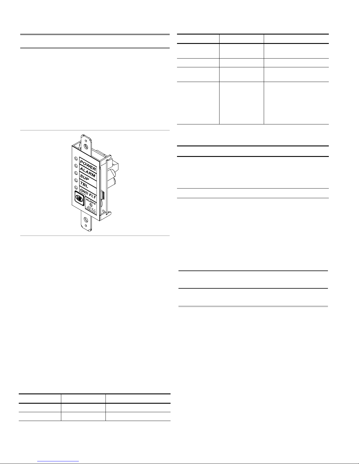
The Remote System Indicator (FSRSI) is a supervised remote
annunciator that provides remote LED indication of power,
alarm, supervisory, trouble, and ground fault conditions. A
sounder gives audible indication during a trouble, alarm, or
supervisory condition. The sounder can be silenced with the
FSRSI Silence switch.
Note: You must run the Find Annunciators program option
after adding or removing a remote annunciator. The remote
annunciators will not operate properly until the panel detects
them. For more information see Chapter 3 “Programming.”
LED State Description
Supervisory
(yellow)
Trouble (yellow) On System trouble
Ground fault
(yellow)
Buzzer On
On Active supervisory device
On System ground fault
System trouble
On (temporal)
On (slow pulse)
On (intermittent)
Off
Alarm condition
Supervisory condition
AC fail
Normal or silenced
Jumper setup
Jumper Name Description
J2 Group
jumper
Note: For jumper location, refer to the FSRSI wiring diagram.
Allows two FSRSIs to be connected
to the same panel.
Install the jumper on only one of the
two FSRSIs.
Specifications
Max. per system: 2
Voltage range
Minimum: 21 Vdc
Maximum: 25 Vdc
Current requirements
Standby: 12 mA
Alarm: 48 mA
Max. circuit capacitance: 0.03 µF
Max. circuit resistance: 13 ohms
Wire size
Minimum: 18 AWG (0.75 sq mm)
Maximum: 12 AWG (2.5 sq mm)
Compatible electric box: ANSI/NEMA OS1-1996 1-3 gang
electrical box
Operating environment
Temperature: 32 to 120 °F (0 to 49 °C)
Humidity: 93% RH, noncondensing
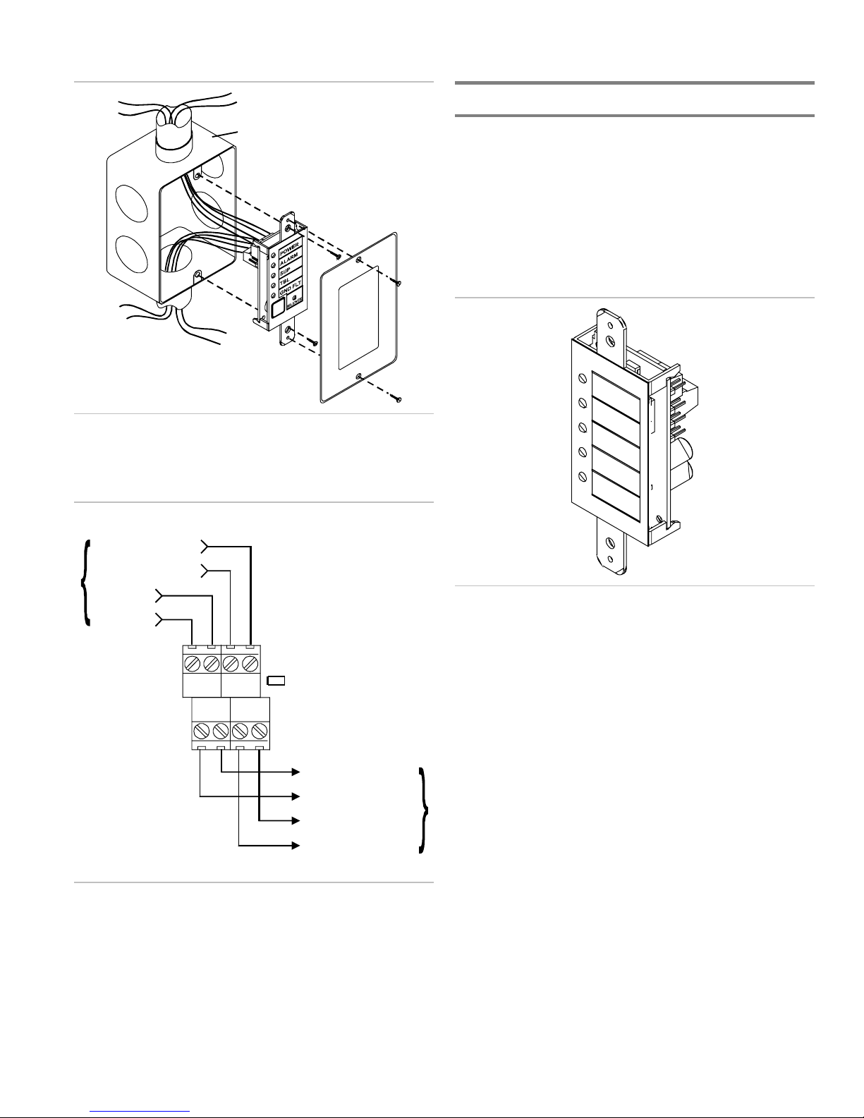
Installation instructions
A single FSRSI can be mounted in a standard, single gang
electrical box (ANSI/NEMA OS1-1996) using the single gang
cover plate that is included. Up to three FSRZI-As with or
without an FSRSI can be mounted in an approved multiple
gang electrical box (ANSI/NEMA OS1-1996) with
appropriate two, three, or four gang cover plates (model
numbers FSAT-2, FSAT-3, or FSAT-4).
Caution: Make sure all power is disconnected from the panel
before installing. Observe static-sensitive handling practices.
To install the FSRSI:
1. Verify that all field wiring is free of opens, shorts, and
ground faults.
2. Connect wires to the FSRSI as shown (see wiring diagram).
3. Using the two plain machine screws provided, mount the
module to the electrical box.
Note: If you are using a surface mounting box, you must
install washers (provided) between the FSRSI and the
surface mounting box.
LEDs and buzzer
LED State Description
Power (green) On AC power present
Alarm (red) On Active alarm state
2.2 FireShield Technical Reference Manual
4. Using the white machine screws provided with the
faceplate, mount the faceplate to the module.
5. Connect the wires to the terminals in the control panel.
6. Program the FSRSI using the Find Annunciators program
option. Refer to Chapter 3 “Programming.”
Page 13
Installation
Installing the Remote Zone Indicator
Compatible electrical box
Installing the FSRSI in an electrical box
Wiring diagram
From control panel
or pr evious device
Communication in -
Communication in +
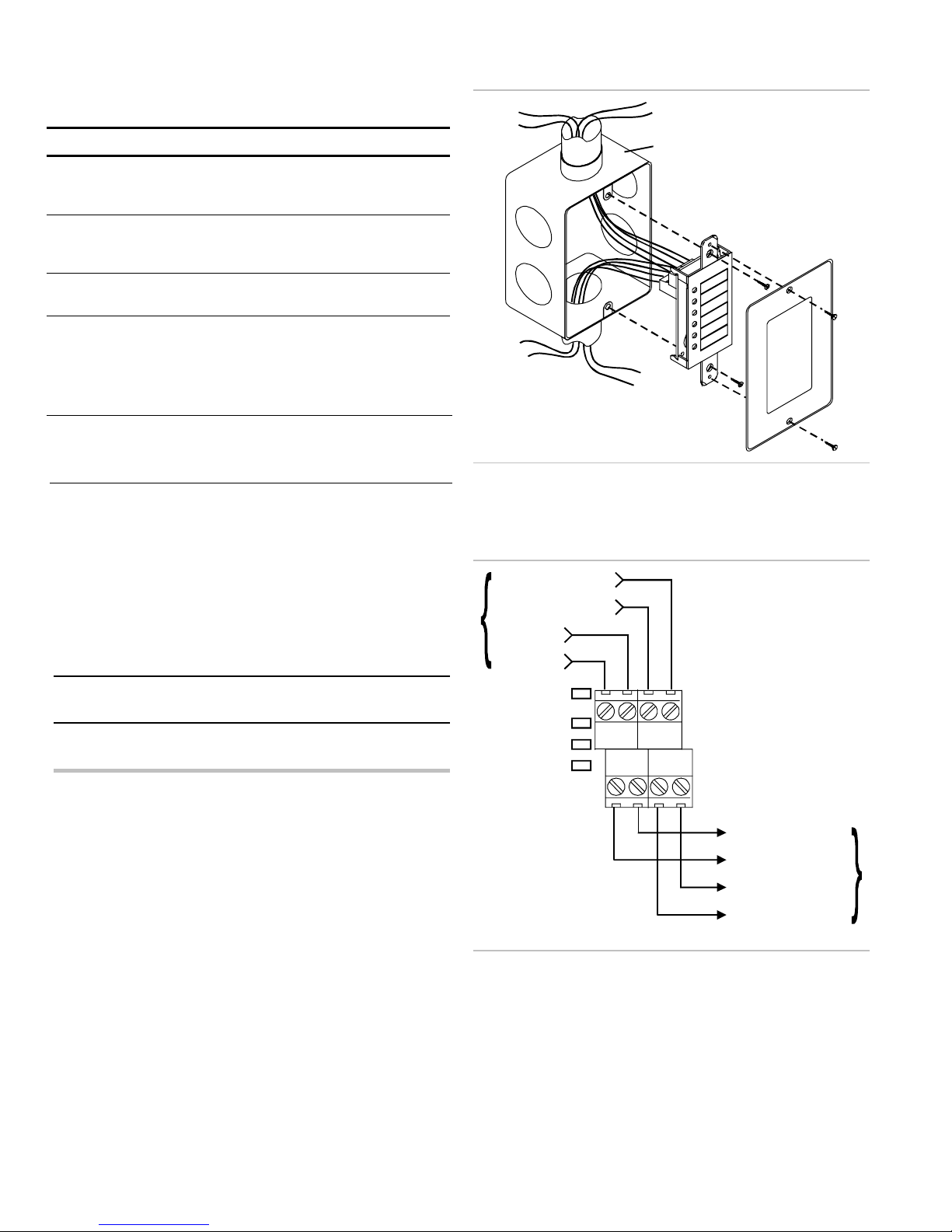
The Remote Zone Indicator (FSRZI-A) is a supervised remote
annunciator that provides remote LED indication of IDCs in
alarm state. The FSRZI-A indicates conditions for five IDCs.
The IDC groups are set by jumpers to indicate zones 1–5 or
zones 6–10. Paper inserts are provided for labeling the LEDs.
Note: You must run the Find Annunciators program option
after adding or removing a remote annunciator. The remote
annunciators will not operate properly until the panel detects
them. For more information see Chapter 3 “Programming.”
24 V in +
24 V in -
Group
C OUT
+ -
J2
24 V out +
24 V out -
Communication out -
Communication out +
To next devi ce
Notes
24V IN
- +
24V OUT
- +
C IN
+ -
1. All wiring is supervised and power limited.
2. 24 V out (aux power) must be programmed as nonresettable.
Specifications
Max. per system
FS302 (three-zone): 2
FS502 (five-zone): 2
FS1004 (ten-zone): 4
Voltage range
Minimum: 21 Vdc
Maximum: 25 Vdc
Current requirements
Standby: 8 mA
Alarm: 35 mA
Max. circuit capacitance: 0.03 µF
Max. circuit resistance: 13 ohms
Wire size
Minimum: 18 AWG (0.75 sq mm)
Maximum: 12 AWG (2.5 sq mm)
Compatible electric box: ANSI/NEMA OS1-1996 1-3 gang
electrical box
Operating environment
Temperature: 32 to 120 °F (0 to 49 °C)
Humidity: 93% RH, noncondensing
FireShield Technical Reference Manual 2.3
Page 14
Installation
Jumper setup
Jumper Name Description
J2 Reserved
N/A
for future
use
J3 Zone 6 -
10
Sets the five LEDs to report alarms
in zones 6 - 10. [1]
jumper
J4
Zone 1- 5
jumper
J5 Group
jumper
Sets the five LEDs to report alarms
in zones 1 - 5. [1]
Allows two FSRZI-As to be
connected to the same panel and
set to the same zone output option.
Install the jumper on FSRZI-As in
only one of the two groups.
[1] Install only one zone jumper on J3 or J4.
Note: For jumper location, refer to the FSRZI-A wiring
diagram.
Installation instructions
A single FSRZI-A can be mounted in a standard, single gang
electrical box (ANSI/NEMA OS1-1996) using the single gang
cover plate that is included. Up to three FSRZI-As with or
without an FSRSI can be mounted in an approved multiple
gang electrical box (ANSI/NEMA OS1-1996) with
appropriate two, three, or four gang cover plates (model
numbers FSAT-2, FSAT-3, or FSAT-4).
Caution: Make sure all power is disconnected from the panel
before installing. Observe static-sensitive handling practices.
To install the FSRZI-A:
1. Verify that all field wiring is free of opens, shorts, and
ground faults.
2. Connect wires to the FSRZI-A as shown (see wiring
diagram).
3. Using the two plain machine screws provided, mount the
module to the electrical box.
Note: If you are surface mounting the FSRZI-A, you must
install washers (provided) between the FSRZI-A and the
surface mount box.
4. Using the two white machine screws provided with the
faceplate, mount the faceplate to the module.
5. Connect the wires to the terminals in the control panel.
6. Program the FSRZI-A using the Find Annunciators
program option. Refer to Chapter 3 “Programming.”
Compatible electrical box
Installing the FSRZI-A in an electrical box
Wiring diagram
Communication in -
Communication in +
24 V in +
24 V in -
From control
panel or
previous
device
Notes
1. All wiring is supervised and power limited.
2. 24 V out (aux power) must be programmed as nonresettable.
J5
J4
J3
J2
24V IN
- +
24V OUT
- +
C IN
+ -
C OUT
+ -
24 V out +
24 V out -
Communication out -
Communication out +
To next device
2.4 FireShield Technical Reference Manual
Page 15

Installation
Installing the Remote Relay Module
The Remote Relay Module (FSRRM) provides five dry
contact relay outputs. The outputs can be wired as both
normally open and normally closed. The outputs can be set to
common or zone notifications (see the “Command options”
table below). Installing the appropriate jumper (JP3 - JP5)
configures the dry contact relay output options.
Five diagnostic LEDs provide visual indication of the status of
each relay. If the LED is lit, the relay is energized. If the LED
is off, the relay is de-energized. If configured for common
operation the trouble relay and the power relay will be
energized when the system is normal.
Note: You must run the Find Annunciators program option
after adding or removing a remote annunciator. The remote
annunciators will not operate properly until the panel detects
them. For more information see Chapter 3 “Programming.”
ACTIVE
IN
OUT
DS4
OUT 1
DS5
OUT 2
DS2
OUT 3
DS3
OUT 4
DS1
OUT 5
TB1 TB2 TB3 TB4
DISABLE
JP1
OUTPUTS
JP1 IN
MODULE TYPE
JP2
ZONE 11-15
JP3
ZONE 6-10
JP4
ZONE 1-5
JP5
COMMON
GROUP
JP6
#1
JP6
JP6
#2
Specifications
Max. per system
FS302 (three-zone): 4
FS502 (five-zone): 4
FS1004 (ten-zone): 6
Voltage range
Minimum: 21 Vdc
Maximum: 25 Vdc
Zoned operation current requirements
Standby: 8 mA
Alarm: 65 mA
Common operation current requirements
Standby: 30 mA
Alarm: 41 mA
Max. circuit capacitance: 0.03 µF
Max. circuit resistance: 13 ohms
Relay ratings: 30 Vdc @ 1 A (resistive load)
Wire size
Minimum: 18 AWG (0.75 sq mm)
Maximum: 12 AWG (2.5 sq mm)
Mounting: MFC-A cabinet or listed fire alarm enclosure
Operating environment
Temperature: 32 to 120 °F (0 to 49 °C)
Humidity: 93% RH, noncondensing
Jumper setup
Jumper Name Description
JP1 Disable
jumper
JP2 Reserved for future use.
JP3 Zone 6 -
10 jumper
JP4 Zone 1- 5
jumper
JP5
Common
jumper
JP6 Group
jumper
[1] Install only one zone jumper on J3 or J4 or J5.
Disables all outputs. This allows the
installer to test the system while the
FSRRM is disabled. Removing the
jumper reactivates the FSRRM.
The disable jumper is supervised.
With the disable jumper in place, the
panel displays Trouble, Annunciator
Trouble, Disable, sounds the panel
buzzer, and de-energizes any
energized relay.
Sets the five dry contacts to report
events on zones 6 through 10. See
“Command options” table. [1]
Sets the five dry contacts to report
events on zones 1 through 5. See
“Command options” table. [1]
Sets the five dry contacts to report
common events. See “Command
options” table. [1]
The group jumper (JP6) allows two
FSRRMs to be connected to the
same panel and set to the same
output option. Install the jumper (JP6)
to only one of the two grouped
FSRRMs.
Command options
Module type Jumper Output 1 Output 2 Output 3 Output 4 Output 5
Common JP5 Alarm Trouble [1] Supervisory Monitor Power [1]
Zone 1 - 5 JP4 Zone 1 Zone 2 Zone 3 Zone 4 Zone 5
Zone 6 - 10 JP3 Zone 6 Zone 7 Zone 8 Zone 9 Zone 10
[1] Under normal conditions the relay is energized (the internal LED is lit). Loss of power de-energizes the relay.
FireShield Technical Reference Manual 2.5
Page 16

Installation
Installation instructions
The FSRRM snaps into a snap track (shipped with the
FSRRM), which mounts inside a listed fire alarm enclosure.
The FSRRM can be positioned in the snap track with the
terminal block facing vertically or horizontally.
Caution: Make sure all power is disconnected from the panel
before installing. Observe static-sensitive handling practices.
To install the FSRRM:
1. Mount the MFC-A cabinet using the installation sheet
provided (P/N 387453).
2. Drill mounting holes in the snap track using the template
provided (P/N 3100463). These holes will align to the
mounting holes on the MFC-A. An optional extended
track (P/N FSRRM-S11) is available for mounting two to
four FSRRM modules.
3. Mount the snap track to the MFC-A cabinet.
MFC-A
Snap
track
Snap
track
5. Verify that all wiring is free of opens, shorts, and ground
faults.
6. Connect the FSRRM to the panel or other peripheral
devices.
7. Power up the panel and confirm that all relays are in the
correct state before connecting the field wiring.
8. Connect field wires to the FSRRM as shown in the wiring
diagram. Be sure connection will not adversely affect
controlled devices (e.g. elevators, fans, etc.).
9. Connect wiring to the controlled devices.
10. Program the FSRRM using the Find Annunciators
program option. Refer to Chapter 3 “Programming.”
Wiring diagram
From control panel
or previous d evice
Communication in +
Communication in -
24 V in -
24 V in +
[1]
[1]
[1]
[2] [2]
To next device
Communication out -
Communication out +
MFC-A
Snap
track
Snap
track
4. Insert one side of the FSRRM into the first snap track slot
and snap in the opposite side.
Mount in first
slot only
RRM
Snap tr ack
C IN
24V IN
+ -
24V OUT
+ -
C OUT
- +
- +
[2] [2] [2]
OUT 5
X
NO C NC
OUT 3
NO C NC
OUT 4
NO C NC
OUT 1
NO C NC
NO C NC
[1]
OUT 2
24 V out -
24 V out +
To next device
Notes
[1] Supervised and power limited.
[2] Must be connected to a power limited source.
3. 24 V out (aux power) must be programmed as nonresettable.
Service and troubleshooting
If the Disabled and Annunc Trouble LED are lit but no IDC or
NAC is disabled then the FSRRM output is disabled.
2.6 FireShield Technical Reference Manual
Page 17

Installation
Installing the Power Expander
Transformer
The Power Expander Transformer (XTR3A120, XTR3A230)
provides additional primary AC power to increase the NAC
capacity for the ten-zone panel. It provides an additional 2.5
amps of NAC current. The Power Expander Transformer
installs in the cabinet with four nuts (provided). The input side
of the Power Expander Transformer connects to 120 Vac or
230 Vac through the Dual Transformer AC Wiring Block. Its
output connects to the circuit board (J4) with the attached
cable harness. One Power Expander Transformer can be
installed in the 10-zone panel.
Note: The Power Expander Transformer does not work with
the three-zone or five-zone panels.
3. Connect the cable harness to J4 on the circuit board. Push
the cable harness until the connector clicks into place.
4. Connect the incoming power wires to the dual transformer
AC wiring block above the existing transformer.
5. Secure the incoming power wires to the side of the control
panel with the tie strap provided.
From 120 Vac, 15 A, 60 Hz
Dedicated branch circuit
—OR—
From 230 Vac, 15 A, 50/60 Hz
Dedicated branch circuit
LN
Cabinet
Main AC
wiring block
and fuse
holder
Fuse
Dual transformer
AC wiring block
Specifications
Power input
120 Vac @ 60 Hz (P/N XTR3A120)
230 Vac @ 50/60 Hz (P/N XTR3A230)
Operating environment
Temperature: 32 to 120 °F (0 to 49 °C)
Humidity: 93% RH, noncondensing
Fuse: Primary winding has thermal current protection and is
not field serviceable
Note: Input current rating is included with the overall ten-zone
ratings.
Installation instructions
Caution: Make sure all power is disconnected from the panel
before installing. Observe static-sensitive handling practices.
To install the Power Expander Transformer:
1. Position the Power Expander Transformer so that the
mounting holes align with the four mounting studs on the
control panel cabinet.
N2 L2
NL
Main
Tie wrap
mounts
Power Expander Transformer installation and wiring
Main
transformer
XTR
(optional
transformer)
controller
board
TB1
Mounti ng
studs
Plug connector
J4
2. Secure the transformer to the panel using the four nuts
provided.
FireShield Technical Reference Manual 2.7
Page 18

Installation
Installing the FSDACT
The FSDACT is a digital alarm communicator transmitter
(DACT) that transmits panel events to a compatible digital
alarm communicator receiver (DACR). Messages are
transmitted over standard loop-start telephone lines. The dialer
is capable of split reporting to two different account and
telephone numbers.
In addition to the DACT functions, this module includes:
• An alphanumeric LCD to display
programming prompts
• An event history log of panel and DACT events, viewable
through compatible software
• A modem for uploading and downloading panel
configuration, history, and current status to a PC running
compatible software
Note: The FSDACT modem is only rated for 2400 baud
communication. Some PC modems may not be compatible
with this baud rate.
The FSDACT can be programmed to operate as a single or
dual line DACT/Modem/LCD display, a Modem/LCD
display, or an LCD display only. For the FSDACT to be
NFPA 72 CS compliant, the following is required:
1. The factory installed warning label must be removed from
the FSDACT's line two phone jack.
2. A second phone line, independent of that used for line one
must be connected to phone jack two.
3. The FSDACT must be programmed for dual line
operation.
4. The FSDACT must be programmed for a daily
transmission test frequency.
UL 864 compliance requires the dual line setting.
The FSDACT can be configured for attended or unattended
downloading. JP1 is a wire loop (located near the top of the
FSDACT) that controls which download method is used.
Leaving the JP1 wire loop intact configures the FSDACT for
attended downloading. The panel will not allow changes to the
panel or dialer configuration unless the program jumper is
inserted. It will allow changes to receiver information (account
code, telephone numbers, etc.). UL requires the red wire loop
to be intact for all remote station systems.
system messages and
changes shall be 100 percent tested. In addition, 10 percent of
initiating devices that are not directly affected by the change,
up to a maximum of 50 devices, also shall be tested, and
correct system operation shall be verified. A revised record of
completion in accordance with 1-6.2.1 shall be prepared to
reflect any changes.”
For additional download security, the FSDACT can be
programmed to perform a call back function. This call back
option applies whether the FSDACT is configured for
attended or unattended downloading.
Specifications
Current requirements
Standby: 40 mA
Alarm: 60 mA
Operating environment
Temperature: 32 to 120 °F (0 to 49 °C)
Humidity: 93% RH, noncondensing
Phone line type: one or two loop-start lines on a public,
switched network
Phone line connector: RJ31/38X (C31/38X). Two 7 ft plug
cords are shipped with the FSDACT.
FCC registration number: US: EDWAL01BFSDACT
Ringer equivalence number: 0.1
Industry Canada Registration number: IC: 3944-FSDACT
Connection between panel and FSDACT: 6-pin connector
Communication formats: Contact ID (SIA DC-05) and
EST 4/2 (SIA DC-02 P3 with hexadecimal event codes)
Installation instructions
Note: It is not necessary to remove the main panel board from
the cabinet to install the dialer.
Cutting the JP1 wire loop configures the FSDACT for
unattended downloading. This means that the program jumper
need not be inserted to accept any panel or dialer
configuration changes.
NFPA 72 1999 edition states in 7-1.6.2.1 that reacceptance
testing shall be performed after any change to site-specific
software.
"All components, circuits, systems operations, or site-specific
software functions known to be affected by the change or
identified by a means that indicates the system operational
2.8 FireShield Technical Reference Manual
Caution: Make sure all power is disconnected from the panel
before removing or installing an FSDACT. Failure to
disconnect power will damage the panel and the FSDACT.
Observe static-sensitive handling practices.
To install the FSDACT:
1. Remove the blank insert from the display window.
2. Remove the clear protective plastic film from the
FSDACT LCD display.
Page 19

Installation
3. Use JP1 to configure the FSDACT for attended or
unattended downloading:
• Attended: leave the JP1 wire intact
• Unattended: cut the JP1 wire
4. Install the dialer to the back of the circuit board. Align the
LCD display with the opening in the circuit board.
5. Secure the dialer to the circuit board with the two
machine screws provided.
6. Connect the power cable to J2 on the control panel.
7. Connect RJ31X/C31X jacks to the supplied cables.
8. Connect the telephone circuits as required.
Line 1
Line 2
Phone cables
(supplied)
JP1 jumper wire
To w all
phone jack
RJ31 jacks
FCC Information
1. The dialer complies with Part 68 of the FCC rules. The dialer’s FCC
certification number and Ringer Equivalence Number (REN) is
displayed on the panel’s programming label and in this manual. This
information must be provided to the telephone company if requested.
2. Two FCC compliant telephone cords with 8-pin modular plugs at both
ends are supplied with the FSDACT. The dialer is designed to be
connected to the telephone network using the supplied cord and an
RJ31X or RJ38X jack, which must also comply with FCC Part 68 rules.
3. The REN is used to determine the maximum number of devices that may
be connected to a single telephone circuit. All telephone devices are
assigned a REN. The sum of the RENs for all connected devices may
not exceed five. The maximum REN may vary in some areas. Contact
the local telephone provider for more information.
4. If the dialer causes harm to the telephone network, the telephone
company will notify you an advance that temporary discontinuance of
service may be required. If advance notice is not practical, the telephone
company will notify you as soon as possible. You will also be advised of
your right to file a complaint with the FCC, if you believe it is
necessary.
5. The telephone company may make changes in its facilities, equipment,
operations, or procedures that could affect the operation of the dialer. If this
happens, the telephone company will provide advance notice in order for
you to make necessary modifications to maintain uninterrupted service.
6. If trouble is experienced with the dialer, for repair or warranty
information, contact the manufacturer at: (941) 739-4200. If the dialer is
causing harm to the telephone network, the telephone company may
request you disconnect the dialer until the problem is resolved.
7. No repairs may be performed on the dialer by the user.
8. The dialer can not be used on public coin phones or party line service
provided by the telephone company.
Circuit board
FSDACT installation and telephone circuit connection
The FSDACT is listed for use with the following DACRs
Receiver Models Formats
Ademco 685 EST 4/2*, Contact ID
FBII CP220 EST 4/2*, Contact ID
Osborne-Hoffman OH 2000 EST 4/2*, Contact ID
Radionics D6500 EST 4/2*
Silent Knight 9000 EST 4/2*
Sur-Gard MLR1, MLR2,
MCDI TLR, TLR+
* EST 4/2 is SIA DCS-02 P3 with the ability to transmit hexadecimal
event codes.
EST 4/2*, Contact ID
Industry Canada Information
NOTICE: This equipment meets the applicable Industry Canada Terminal
Equipment Technical Specifications. This is confirmed by the registration
number. The abbreviation, IC, before the registration number signifies that
registration was performed based on a Declaration of Conformity indicating
that Industry Canada technical specifications were met. It does not imply that
Industry Canada approved the equipment.
Before installing this equipment, users should ensure that it is permissible to
be connected to the facilities of the local telecommunications company. The
equipment must also be installed using an acceptable method of connection.
The customer should be aware that compliance with the above conditions may
not prevent degradation of service in some situations.
Repairs to certified equipment should be coordinated by a representative
designated by the supplier. Any repairs or alterations made by the user to this
equipment, or equipment malfunctions, may give the telecommunications
company cause to request the user to disconnect the equipment.
Users should ensure for their own protection that the electrical ground
connections of the power utility, telephone lines, and internal metallic water
pipe system, if present, are connected together. This precaution may be
particularly important in rural areas.
Caution: Users should not attempt to make connections themselves, but
should contact the appropriate electric inspection authority, or electrician, as
appropriate.
NOTICE: The Ringer Equivalence Number (REN) for this terminal
equipment is 0.1. The REN assigned to each terminal equipment provides an
indication of the maximum number of terminals allowed to be connected to a
telephone interface. The termination on an interface may consist of any
combination of devices subject only to the requirement that the sum of the
Ringer Equivalence Numbers of all the devices does not exceed five.
FireShield Technical Reference Manual 2.9
Page 20

Installation
Connecting an RPM module
The Reverse Polarity Module (RPM) is an interface between
FireShield and a reverse polarity receiver. It provides offpremises signal transmission for systems that must comply
with NFPA requirements. When used as a reverse polarity
remote station transmitter, it can be connected to either a
single circuit (alarm or alarm and trouble) or up to three
circuits (alarm, supervisory, and trouble).
Note: For detailed information and wiring, refer to the RPM
installation sheet P/N 3100430.
Below are application diagrams for using the RPM.
Note: The RPM must be mounted in an MFC-A enclosure
immediately adjacent to the panel and in conduit.
Alarm transmitted only
FireShield
TB3
NO
C
TRBL
NC
NO
SUP
NO
ALM
C-
C+
24VOUT
+
From ALRM on RPM
(brown wire)
From COM on RPM
(black wire)
From +24 on RPM
(red wire)
Alarm and trouble transmitted on a single circuit
Note:
JP1 on the RPM must be OUT.
FireShield
TB3
From TRBL on RPM
(yellow wire)
TRBL
NO
C
NC
NO
SUP
NO
ALM
From ALRM on RPM
(brown wire)
C-
C+
From COM on RPM
24VOUT
+
(black wire)
From +24 on RPM
(red wire)
Alarm, supervisory, and trouble transmitted on separate
circuits
Note: JP1 on the RPM must be IN.
FireShield
TB3
From TRBL on RPM
(yellow wire)
TRBL
NO
C
NC
NO
SUP
NO
ALM
From SUPV on RPM
(orange wire)
From ALRM on RPM
(brown wire)
C-
C+
From COM on RPM
24VOUT
+
(black wire)
From +24 on RPM
(red wire)
2.10 FireShield Technical Reference Manual
Page 21

Installation
_
_
_
_
A
Connecting a CTM module
The CTM4.7 City Tie Module is an interface between the
control panel notification appliance circuit and a master box. It
provides off-premises signal transmission for systems that
must comply with NFPA requirements for Auxiliary
Protective Systems. The CTM4.7 activates a local energy fire
alarm box, which provides a 24 Vdc alarm signal (current
limited at 200 mA). The 4.7 KΩ end of line resistor required
by the NAC is built in to the CTM4.7.
Requirements
When connecting a CTM to the panel, the following hardware
and programming requirements must be met:
• The NAC used must be dedicated to CTM use only
• All alarm zones must be programmed to activate the
dedicated NAC
• The NAC used must not be programmed for Signal
Silence
Specifications
Power: Nominal 24 Vdc @ 200 mA
Municipal box operation: Nominal 24 Vdc
Maximum wiring resistance: 25 Ω
Trip current: 200 mA into 14.5 Ω coil
Maximum current: 300 mA
Standby current: 20 mA
Mounting: Single gang box
Operating environment
Temperature: 32 to 120 °F (0 to 49 °C)
Humidity: 93% RH, noncondensing
Panel in alarm condition
larm condition
Master box
CTM4.7
[2]
+
[1]
+
1
[5]
2
Municipal circuit
+
_
[4]
_
+
[3]
Notification
2
1
appliance circuit
Notes
[1] 200 mA into a 14.5 Ω trip coil max., loop resistance = 25 Ω
[2] This circuit is nonpower-limited and is supervised for
grounds and opens, but not shorts
[3] Supervised and power-limited
[4] NAC must be programmed for continuous signal
[5] CTM4.7 must be mounted in the same room as the panel
The following are wiring diagrams showing how the polarity
switches during an alarm condition.
Panel in normal condition
Normal condition
Master box
CTM4.7
_
+
[4]
+
_
[3]
Notification
1
2
2
1
[5]
+
[1] [2]
+
Municipal circuit
appliance circuit
FireShield Technical Reference Manual 2.11
Page 22

Installation
Connecting an auxiliary power supply
Aux power supplied by the panel cannot exceed 0.5 A. If more
than 0.5 A is required, you must use a compatible UL/ULC
listed fire alarm power supply.
When using an auxiliary power supply, you must connect the
-24 Vdc auxiliary terminal at the panel to the -24 Vdc output
terminal of the listed auxiliary power supply used to power
FireShield devices.
Note: For detailed wiring information, refer to the installation
instructions that came with the auxiliary power supply.
Aux. Power
FireShield
FACP
UL Listed
Aux. Power Source
+
To Devices
24 Vdc @ 0.5 A Max.
-
+
To Devices
Requiring Additional
Power
-
Installing the terminal shield
The terminal shields for the three, five, and ten zone panels
(model numbers ending in GC or GF) required for Canadian
installation, cover and protect the wire connections at the
terminal blocks.
To install the terminal shield:
1. Remove the four corner mounting screws from the circuit
board. Refer to the diagram below for location.
2. Mount the supplied standoffs to the four corner locations
where you removed the screws.
3. Mount the terminal shield to the standoffs using the
screws you removed in step 1. Refer to the diagram
below.
Standoff
2.12 FireShield Technical Reference Manual
Page 23

Chapter 3
T
Programming
Overview
ANNUN
TROUBLE
16 8 4 2 1
Bottom row of LEDs
BAT
TROUBLE
GND
FAULT
Binary numbers
WALK
TEST
SIGNAL
SILENCED
Program options and settings
The features and functions of FireShield can be customized
through programming. To customize the panel, you choose a
program option, then choose a setting for that option. This
chapter shows you how to program the panel.
Programming methods
FireShield panels can be programmed using either of two
methods.
First, you can use the panel’s LEDs and switches, with or
without an FSDACT installed.
Second, you can use a PC with an FSDACT installed. PC
programming requires an optional software package, the
FireShield Configuration Utility (model number FSCU). Refer
to the FSCU online help system for complete programming
instructions.
Programming LEDs
In programming mode, the top row of panel LEDs indicates
which program option is selected. Each LED is assigned a
binary number, and the total value of the top row equals the
option number. If you are not familiar with binary numbers,
you can simply match the pattern of the LEDs with the
programming instructions.
ALARM
16 8 4 2 1
Top row of LEDs
TROUBLE
SUP
Binary numbers
POWER DISABLE
FSDACT display
If you are using the optional FSDACT to program the panel,
each option and setting is displayed on the LCD display.
The top row of the LCD displays the program option, and the
bottom row displays the setting for that option. You can use
the programming buttons to step through the options and
select the settings you want.
Programming buttons
The panel buttons take on a different function when the panel
is in programming mode. The following table shows the
buttons and describes what they do in programming mode.
Button Description
REMOTE
DISCON-
NECT
WAL K
TEST
RESET
SIGNAL
SILENCE
& DRILL
PANEL
SILENCE
Selects the next program option. The top
row of LEDs and the FSDACT LCD change
to show the option selected.
Selects the previous program option. The
top row of LEDs and the FSDACT LCD
change to show the option selected.
Selects the next setting for the current
option. The bottom row of LEDs and the
FSDACT LCD change to show the setting
selected.
Selects the previous setting for the current
option. The bottom row of LEDs and the
FSDACT LCD change to show the setting
selected.
Saves the setting you selected for the
current program option.
Each option has a number of possible settings. The bottom
row of panel LEDs indicates which setting is selected for the
current option. The settings are detailed below in “Custom
programming the panel.” Again, each LED is assigned a
binary number, and the total value of the bottom row equals
the setting number.
The values of all LEDs lit on a single row are added to
determine the option or setting number. For example, if the
Gnd Fault, Walk Test, and Signal Silenced LEDs are lit, the
value is 7 (4+2+1). This means that setting seven for the
current option is selected.
FireShield Technical Reference Manual 3.1
Page 24

Programming
Using the factory default settings
2. Press Remote Disconnect to select the Load Defaults
The panel comes from the factory programmed with a predefined set of defaults. The default settings are:
Option Default setting
Find annunciators None found
Auto signal silence timer None
Aux power reset No
Signal silence/reset inhibit timer None
IDC zone types Alarm (unverified)
All IDCs activate all NACs
IDC class Class B
NAC class Class B
NAC output (NAC1 – NAC4) GENESIS
NAC silenceable Silenceable
For a more detailed list of defaults, see Appendix B,
“Programming templates.”
If you want to use the factory programmed settings as they
are, you do not need to perform any programming. If you do
not want to use the panel’s default settings, refer to “Custom
programming the panel.”
Note: You must run the Find Annunciators program option
after adding or removing a remote annunciator. The remote
annunciators will not operate properly until the panel detects
them. These include the FSRSI, FSRZI-A, and FSRRM.
Reloading the factory default settings
When you reload defaults, you return the panel to the factoryprogrammed settings. The primary purpose for loading the
defaults is to return the panel to its original settings if the need
arises. You can then start fresh by using these settings or
custom program one or more options.
Program option
Top LEDs/LCD
Load Defaults
Key: = OFF, = ON
To reload the default settings:
1. Install program jumper PRG.
Setting
Bottom LEDs/LCD
No
Yes
Description
Do not load default
settings
Load default settings
3. Press Reset to select Yes, the setting to reload the factory
4. Press Panel Silence to perform the reload.
The trouble buzzer sounds a long beep as confirmation.
5. Exit program mode by removing the program jumper or
Using an FSDACT
If you have an FSDACT connected to your system, it must be
recognized by the panel before programming. Also, if you
remove an FSDACT from your system, it must be removed
from the panel’s memory.
To do this, install the program jumper (PRG), then remove the
program jumper. This allows the panel to recognize that an
FSDACT was installed or removed from the system.
Custom programming the panel
FireShield functionality can be custom programmed when the
factory defaults do not meet your needs. The following
options can be custom programmed:
1. Load defaults
2. Find annunciators
3. Auto signal silence timer
4. Aux power reset
5. Signal silence/reset inhibit timer
6. IDC zone types (and NACs that activate)
7. IDC class
8. NAC class
9. NAC output
10. NAC silenceable
11. Program FSDACT (if installed)
Tip: We recommend that you program the options in the order
they are listed. This matches the order of the LEDs as you
increment through each option. The lighting pattern of the
LEDs corresponds to the program option you are
programming and follows the binary number pattern
associated with each row of LEDs.
program option.
default settings.
continue to the next topic to custom program the panel.
Refer to “Custom programming the panel” for more
information.
The panel common LEDs flash and the panel enters a
trouble state. The trouble buzzer sounds.
3.2 FireShield Technical Reference Manual
Page 25

Programming
Getting started
You should complete the programming templates found in
Appendix B before you program the panel. NFPA 72 requires
that you keep a copy of these sheets on file.
The following table and procedures prepare the panel for
custom programming.
1. Program load defaults
In this topic, you do not need to load the defaults. To load the
default settings, see the topic “Reloading the factory default
settings,” above.
Program option
Top LEDs/LCD
Load Defaults
Key: = OFF, = ON
To get started:
1. Install program jumper PRG.
Setting
Bottom LEDs/LCD
No
Yes
Description
Does not load default
settings
Loads the default settings
next option or Walk Test to return to the previous option. To
save your changes, you must press Panel Silence before
advancing to the next option.
2. Program find annunciators
Description: Verifies and logs each remote annunciator
(FSRSI, FSRZI-A, and FSRRM) connected to your system.
Notes
• This process may take up to 40 seconds. During this time
do not remove the program jumper. If the program
jumper is removed, you must power down and power up
the panel to get back into the programming mode.
• The Find Annunciators program option must be
performed if you are using remote annunciators (FSRSI,
FSRZI-A, or FSRRM) or if you add or remove a remote
annunciator from your system.
Program option
Top LEDs/LCD
Find Annunc
Setting
Bottom LEDs/LCD
xx now on bus
Find devices
Description
Does not look for devices.
Logs all devices
connected to the panel.
The top rows of LEDs flash and the panel enters a trouble
state. The trouble buzzer sounds.
2. Press Remote Disconnect to advance to the first
programming option (Load Defaults).
The LEDs stop flashing, the Disable LED (binary value 1)
lights, and “Load Defaults” is displayed on the FSDACT
LCD display (if installed). The trouble buzzer turns off;
however, the panel is still in a trouble state.
The Signal Silenced LED is on, showing that setting No is
selected.
3. You can press Reset to step through the settings available
for this option (No or Yes). Notice how the Signal
Silenced and Walk Test LEDs switch to indicate the
different options.
You are now ready to program your panel.
Notes
• You can exit program mode at any time by removing the
program jumper. All saved program selections remain
intact. When the jumper is removed, the panel resets.
• If no buttons are pressed for 90 seconds, the system
returns to the initial program start state with the top row
of LEDs flashing and the buzzer sounding.
To program the panel
If no programming is required for a particular option, it can be
skipped. You can use Remote Disconnect to advance to the
To find remote annunciators:
1. Press Remote Disconnect to select the program option.
If an FSDACT is installed, the lower line of the LCD
displays “xx now on bus” where xx is the number of
devices (between 0 and 12).
2. Press Reset to select Find devices.
3. Press Panel Silence to begin finding devices.
The bottom row of LEDs flashes and the second line of
the LCD displays “Finding devices” while the panel
searches for all remote annunciators.
When the search is complete, the bottom row of LEDs
shows (in binary) the number of devices found. The
second line of the LCD displays “was xx now yy.” The
number of devices found (now) should equal the number
of devices installed. If not, there is a wiring or device
problem.
4. To end programming now, remove the program jumper.
Otherwise, continue with “Program auto signal silence
timer,” below.
3. Program auto signal silence timer
Description: A timer that, when programmed, automatically
silences the NAC circuits 20 minutes after the last alarm event.
FireShield Technical Reference Manual 3.3
Page 26

Programming
Program option
Top LEDs/LCD
Auto Sig Sil
Setting
Bottom LEDs/LCD
None
Sil aft 20 mins
Description
NACs stay on until Signal
Silence is pressed
NACs automatically turn
off after twenty minutes
To program the auto signal silence timer:
1. Press Remote Disconnect to select the program option.
2. Press Reset to select your setting.
3. Press Panel Silence to save.
The trouble buzzer sounds a long beep as confirmation.
4. Program aux power reset
Description: Causes a temporary interruption of aux power
when Reset is pressed. This is so that four-wire smoke
detectors can be reset. If this is not programmed, pressing
Reset has no effect on the aux power output.
Caution: This option must be set to No (continuous) if remote
annunciators or relays are being used.
Program option
Top LEDs/LCD
Aux Power Reset
To program aux power reset:
Setting
Bottom LEDs/LCD
No
Yes
Description
Continuous 24 Vdc on
AUX PWR terminals
Resettable 24 Vdc on
AUX PWR terminals
1. Press Remote Disconnect to select the program option.
2. Press Reset to select your setting.
3. Press Panel Silence to save.
The trouble buzzer sounds a long beep as confirmation.
5. Program signal silence/reset inhibit timer
Description: Programs all NACs with a one-minute silence
inhibit. This means that, the NACs cannot be silenced and the
panel cannot be reset during their first minute of activation.
Program option
Top LEDs/LCD
Sig Sil Inhibit
Setting
Bottom LEDs/LCD
None
Inhibit one min
Description
Signal Silence/Reset
operational immediately
after NACs turn on
Signal Silence/Reset
operational one minute
after NACs turn on
To program the signal silence/reset inhibit timer:
1. Press Remote Disconnect to select the program option.
2. Press Reset to select your setting.
3. Press Panel Silence to save.
The trouble buzzer sounds a long beep as confirmation.
6. Program IDC zone types
Description: Selects the type and functionality of each IDC.
Note: See the FireShield ULI and ULC compatibility lists P/N
3100468 for restrictions.
Default: Alarm - unverified, with all NACs active
Program option
Top LEDs/LCD
Program IDC
Setting
Bottom LEDs/LCD
Alarm-unverified
Alarm-verified
Retard-waterflow
Description
Alarm-unverified: For
circuits with smoke
detectors and contact
devices. All activations
are immediately
considered as alarms.
Circuit can not be
restored until devices are
restored to normal and
panel is reset.
Alarm-verified: For
circuits with smoke
detectors and contact
devices. 2-wire smoke
detector activations are
verified (delayed and
confirmed) before
activating an alarm. 4-wire
smoke detectors and
contact devices are not
verified and immediately
considered as alarms.
Circuit can not be
restored until devices are
restored to normal and
panel is reset.
Waterflow (retard): For
connection of both vane
type and pressure flow
switches. Device
activation must be
maintained for at least 15
seconds before being
considered an alarm.
NACs activated by
waterflow IDCs can not be
silenced until activated
devices restore to normal
(panel reset not required).
Circuit can not be
restored until devices are
restored to normal and
panel is reset.
3.4 FireShield Technical Reference Manual
Page 27

Programming
Waterflow
Ret-wf/superv
Wf-supervisory
Supervisory
Monitor
Waterflow (no retard):
For connection of both
vane type and pressure
flow switches. Activations
are immediately
considered as alarms.
NACs activated by
waterflow IDCs can not be
silenced until activated
devices restore to normal
(panel reset not required).
Circuit can not be
restored until devices are
restored to normal and
panel is reset.
Waterflow (retard) /
supervisory (latching):
Special IDC that allows
connection of both
waterflow and supervisory
devices on the same 2wire circuit. Requires the
use of two resistors (3.6
kΩ and 1.1 kΩ). The
waterflow portion of the
circuit functions the same
as IDC Type 3 Waterflow
(retard) and the
supervisory portion
functions the same as
IDC Type 7 Supervisory
(latching).
Waterflow (no retard) /
supervisory (latching):
Special IDC that allows
the connection of both
waterflow and supervisory
devices on the same 2wire circuit. Requires the
use of two resistors (3.6
kΩ and 1.1 kΩ). See
“Waterflow (no retard)”
and “Supervisory
(latching)” settings for
additional information.
Supervisory (latching):
For the connection of
supervisory devices.
Momentary activation of
normally open devices
immediately places the
panel in a supervisory
state and turns on
supervisory LEDs and
relays. Circuit can not be
restored until devices are
restored to normal and
panel is reset.
Monitor: Monitoring of
normally open switches
for other functions (fire
door position, etc.). Not
approved for use under
ULC 527 in Canada.
To program IDC zone types:
1. Press Remote Disconnect to select the program option.
For new panels, the Trouble LED of IDC 1 lights.
Otherwise, the Trouble LED of the last IDC programmed
lights. To select an IDC for programming, press the IDC
Disable button.
2. Press Reset to select the desired IDC zone type.
Note: If you program an IDC as a waterflow/supervisory,
a supervisory activation will not turn on the outputs
(NACs and relays). Only a waterflow activation will turn
on the outputs.
3. Program which NAC activates for the IDC.
The Trouble LED for the NAC lights to indicate which
NAC is associated with the IDC. Press the NAC Disable
button to deselect (or reselect) it for activation.
The default is that each alarm or waterflow IDC activates
all NACs. Only alarm, waterflow, and supervisory can
operate NACs. Alarm and supervisory IDCs should not be
assigned to the same NACs. Monitor zones can not be
assigned to NACs.
4. Press Panel Silence to save your selection for the IDC.
The trouble buzzer sounds a long beep as confirmation.
5. Select the next IDC for programming by pressing its
Disable button.
The corresponding Trouble LED lights to indicate your
selection.
6. Program the IDC by repeating steps 2 through 4, above.
Complete this procedure for each IDC before moving on
to the next program option.
7. Program IDC classes
Description: Programs the IDCs as either Class B or Class A.
This option only appears for panels that can be configured as
Class A. All IDC types except the two combination waterflow/
supervisory options can be configured as Class A
For Class A operation, you need to configure a pair of IDCs,
one odd and one even. When you change the class of an IDC,
you must change the class of both IDCs in the pair.
Program option
Top LEDs/LCD
IDC Class
Setting
Bottom LEDs/LCD
Class B
Class A
Description
IDC wired as Class B
IDC wired as Class A
FireShield Technical Reference Manual 3.5
Page 28

Programming
To program IDC classes:
1. Press Remote Disconnect to select the program option.
The last programmed IDC Trouble LED stays lit.
2. Press Reset to select Class A or Class B.
3. Press Panel Silence to save your selection.
The trouble buzzer sounds a long beep as confirmation.
4. Program each IDC class by pressing the IDC Disable
button to light the IDC Trouble LED. When the Trouble
LED is lit, you can program the IDC class by repeating
steps 2 and 3 above.
Note: Make sure you set the IDC jumpers to match the class
for which you program the IDC.
8. Program NAC classes
Description: Programs the NACs as either Class B or Class A.
For Class A operation, you need to configure a pair of NACs,
one odd and one even. When you change the class of an NAC,
you must change the class of both NACs in the pair.
Program option
Top LEDs/LCD
NAC Class
To program NAC classes:
Setting
Bottom LEDs/LCD
Class B
Class A
Description
NAC wired as Class B
NAC wired as Class A
1. Press Remote Disconnect to select the program option.
For new panels, the Trouble LED of NAC 1 lights.
Otherwise, the Trouble LED of the last NAC programmed
lights. To select a NAC for programming, press the NAC
Disable button.
2. Press Reset to select Class A or Class B.
Note: Whenever NAC pairs are programmed for Class A,
output pairs must be programmed for the same output types.
3. Press Panel Silence to save.
Program option
Top LEDs/LCD
NAC Output
Setting
Bottom LEDs/LCD
Continuous
Temporal
GENESIS
Description
NAC outputs
continuous signal: For
strobes and notification
appliances that selfgenerate a temporal
pattern.
NAC outputs temporal
(3-3-3) signal: Universal
3-3-3 pattern required for
evacuation signals by
NFPA 72. Used when
notification appliances are
not capable of selfgenerating a temporal
pattern.
GENESIS sync/silence:
Used with Genesis and
Enhanced Integrity horns
and strobes. Genesis and
Enhanced Integrity
appliances maintain
synchronization per UL
1971. For Genesis
devices, it allows
connected horns to be
silenced while strobes on
the same 2-wire circuit
continue to flash until the
panel is reset.
To program NAC outputs:
1. Press Remote Disconnect to select the program option.
The last programmed NAC Trouble LED stays lit.
2. Press Reset to select your setting.
3. Press Panel Silence to save.
The trouble buzzer sounds a long beep as confirmation.
4. Program the output for each NAC by pressing the NAC
Disable button to light the Trouble LED for that NAC.
When the Trouble LED is lit, you can program the NAC
by repeating steps 2 and 3 above.
Note: Whenever NAC pairs are programmed for Class A,
output pairs must be programmed for the same output
types.
The trouble buzzer sounds a long beep as confirmation.
4. Program each NAC class by pressing the NAC Disable
button to light the NAC Trouble LED. When the Trouble
LED is lit, you can program the NAC class by repeating
steps 2 and 3 above.
Note: Make sure you set the NAC jumpers to match the class
for which you program the NAC.
9. Program NAC outputs
Description: Programs the output of each NAC.
3.6 FireShield Technical Reference Manual
10. Program NAC as Silenceable
Description: Programs the NAC as silenceable. If set to No,
the NAC, when activated, cannot be silenced using the Signal
Silence & Drill button or the auto signal silence feature. It can
only be silenced with a panel reset.
Page 29

Programming
Program option
Top LEDs/LCD
NAC Silenceable
Note: It is not necessary to select this option for waterflow
Setting
Bottom LEDs/LCD
No
Yes
Description
NAC does not turn off
when Signal Silence is
pressed
NAC turns off when
Signal Silence is pressed
IDCs. NACs assigned to waterflow IDCs can not be silenced
as long as the IDC has an active input. The IDC remains in the
alarm state until the panel is reset.
If the auto signal silence feature is programmed, the panel
silences the associated NAC when the waterflow switch is no
longer active and the timer has expired.
If Signal Silence & Drill is pressed when a waterflow circuit is
active, the associated NAC circuit does not silence until the
waterflow condition is no longer active.
To program the NACs as silenceable:
1. Press Remote Disconnect to select the program option.
The last programmed NAC Trouble LED stays lit.
2. Press Reset to select your setting.
3. Press Panel Silence to save.
The trouble buzzer sounds a long beep as confirmation.
4. Program each NAC by pressing the NAC Disable button
to light the Trouble LED for that NAC. When the Trouble
LED is lit, you can program the zone by repeating steps 2
and 3 above.
If you selected Yes, the panel automatically switches to
FSDACT programming mode and “DACT Programming”
is displayed on the LCD. Refer the next topic “FSDACT
programming” for complete programming instructions.
If you selected No, proceed to “Finishing up,” below. You
can return to FSDACT programming at any time.
Tip: If no panel programming is needed, you can go directly to
this program option by following these steps:
1. Insert the program jumper.
2. Press Remote Disconnect.
3. Press Walk Test.
Finishing up
To finish up:
1. Remove the program jumper PRG.
You can store the suitcase jumper on one pin.
2. Panel programming is complete.
3. The panel will reset. At the conclusion of the reset, make
sure the panel is free of troubles. If IDC or NAC trouble
LEDs are on, check to see that the jumper settings match
the program options selected.
4. Test all circuits and panel functions to make sure that the
panel was programmed correctly.
11. Programming the FSDACT
Description: Initiates the FSDACT for programming. This
option is not displayed if you do not have a FSDACT; you can
proceed to “Finishing up,” below.
Program option
Top LEDs/LCD
Program DACT
To program the FSDACT:
Setting
Bottom LEDs/LCD
No
Yes
Description
Does not switch to
FSDACT programming
mode.
Automatically switches
the panel to FSDACT
programming mode.
1. Press Remote Disconnect to select the program option.
2. Press Reset to select Yes or No.
3. Press Panel Silence to save.
The trouble buzzer sounds a long beep as confirmation.
FireShield Technical Reference Manual 3.7
Page 30

Programming
FSDACT programming
Programming the FSDACT sets up the dialer for
communication with the central monitoring station. It also sets
a number of other options such as date, time, phone numbers,
etc. Many of the options have default settings, which are
detailed below. These settings can be changed if desired.
Programming buttons
The panel buttons function in the following way when in
FSDACT programming mode.
Button descriptions
Button Description
REMOTE
DISCON-
NECT
WAL K
TEST
RESET
SIGNAL
SILENCE
& DRILL
PANEL
SILENCE
Tip: In this chapter we tell you to press Reset to scroll through
each list of settings. However, to enter a setting that’s near the
end of the list, it may be faster to press Signal Silence & Drill
to move backwards through the list of selections.
Digit descriptions
The following table describes the function of each digit that
can be entered in FSDACT programming fields.
Digit Telephone number 4.2 event codes
Selects the next program option
Selects the previous program option
Selects the next setting for the current option.
Also increments through the digits of numeric
entries such as telephone numbers
Selects the previous setting for the current
option
Also decrements through the digits of numeric
entries such as telephone numbers
Saves the setting you selected for the current
program option
Advances cursor to the next digit of a field
(e.g. entering a phone number)
Note: When pressed in the last digit of a field,
the information is saved and the next program
option is displayed
Digit Telephone number 4.2 event codes
D Hexadecimal D (13)
E Hexadecimal E (14)
F Terminator (indicates
last digit)
* DTMF *
# DTMF #
, DTMF , (used for a
pause between digits)
Hexadecimal F (15)
Getting started
You should complete the programming templates found in
Appendix B before you program the panel. NFPA 72 requires
that you keep a copy of these sheets on file.
Follow the steps below to prepare the panel for FSDACT
programming. If you are already in programming mode, skip
the first three steps and start at number four below.
To get started:
1. Install program jumper PRG.
Panel common LEDs flash and the panel enters a trouble
state. The trouble buzzer sounds.
2. Press Remote Disconnect to advance to the first
programming option (Load Defaults).
The LEDs stop flashing, the Disable LED (binary 1) lights,
and Load Defaults is displayed on the LCD. The trouble
buzzer turns off; however, the panel is still in a trouble
state.
3. Do not load defaults. Press Walk Test until “DACT
Programming” is displayed.
4. Press Reset until Yes is selected.
5. Press Panel Silence to begin FSDACT programming.
The panel automatically switches to FSDACT
programming mode and “DACT Programming” is
displayed on the LCD.
6. Enter your password. Refer to “Programming the
FSDACT” below.
Note: You can exit from programming mode at any time by
removing the program jumper. All saved program selections
will remain intact.
0 to 9 Numeric digits Numeric digits
A DTMF A Hexadecimal A (10)
B DTMF B Hexadecimal B (11)
C Hexadecimal C (12)
3.8 FireShield Technical Reference Manual
Page 31

Programming
Programming the FSDACT
When you program the FSDACT, you’ll follow these general
steps:
1. Enter your passcode
2. Load default settings
3. Edit your passcode
4. Enter the date
5. Enter the time
6. Select the FSDACT mode
7. Enter the (DACR1) primary phone number
8. Enter the (DACR1) secondary phone number
9. Enter the (DACR1) account code
10. Select the DACR1 alarm format
11. Select the restore option for CMS one
12. Enter retry count one
13. Enter retry time one
14. Enter the (DACR2) primary phone number
15. Enter the (DACR2) secondary phone number
16. Enter the (DACR2) account code
17. Select the DACR2 alarm format
18. Select the restore option for CMS two
19. Enter retry count two
20. Enter retry time two
21. Select tone or pulse dialing
22. Select AC fail delay time
23. Enter the transmission test time
24. Select the transmission test frequency
25. Enter the number of rings to answer
26. Select the ring type
27. Enable (disable) call back
28. Enter the call back phone number
Tip: If you save an incorrect digit, press Walk Test then
Remote Disconnect. This returns the cursor to the first digit.
Press Panel Silence until the cursor is at the incorrect digit.
Enter the correct digit, then press Panel Silence to save and
advance to the next digit.
3. Press Reset (or Signal Silence & Drill) until the next digit
of your passcode is displayed.
4. Press Panel Silence to save and advance to the next digit.
5. Repeat steps 3 and 4 until all digits are entered.
6. When you press Reset at the last digit, the system
automatically advances you to the next program option.
2. Load default settings
Description: Loads the factory default settings for each
program option.
Settings: Yes = Loads the default settings
No = Does not load the default settings
Default: No
To load default settings:
1. Press Reset to select Yes or No.
2. Press Panel Silence to save and advance to the next
program option.
The trouble buzzer sounds a long beep as confirmation.
3. Edit your passcode
Description: You have the option to change your passcode or
continue with programming.
Format: 7 digits
Default: No default
To skip changing your passcode:
1. Press Remote Disconnect to advance to the next program
option.
To change your passcode:
1. Enter your passcode
Description: Access to dialer programming is passcode
restricted. For security, the default passcode should be
changed as part of the installation. (To change the passcode,
refer to “Edit passcode,” below.)
Format: 7 digits
Default: 1111111
To enter your passcode:
1. Press Reset (or Signal Silence & Drill) to scroll through
the setting list until the first digit of your passcode is
displayed.
2. Press Panel Silence to save and advance to the next digit.
The trouble buzzer sounds a long beep as confirmation.
FireShield Technical Reference Manual 3.9
1. Press Reset until the first digit of your new passcode is
displayed.
2. Press Panel Silence to save and advance to the next digit.
The trouble buzzer sounds a long beep as confirmation.
3. Press Reset until the next digit is displayed.
4. Press Panel Silence to save and advance to the next digit.
5. Repeat steps 3 and 4 until all digits are entered.
6. When you press Panel Silence at the last digit, the system
automatically advances you to the next program option.
4. Enter the date
Description: Sets the current date.
Format: MMDDYYYY
Default: 01012002
Page 32

Programming
Tip:
Don’t forget that you can press Reset or Signal Silence &
Drill to scroll through the list of settings. It may be faster to
press Signal Silence & Drill to scroll backwards through the
settings.
To enter the current date:
1. Press Reset until the correct month is displayed.
2. Press Panel Silence to save the month setting and advance
to the day setting.
The trouble buzzer sounds a long beep as confirmation.
3. Press Reset until the correct day is displayed.
4. Press Panel Silence to save the day setting and advance to
the year setting.
The trouble buzzer sounds a long beep as confirmation.
5. Press Reset until the correct year is displayed.
6. Press Panel Silence to save the year setting and advance
to the next option.
The trouble buzzer sounds a long beep as confirmation.
5. Enter the time
Description: Sets the current time.
Format: HHMM
Default: 0000
To enter the current time:
1. Press Reset until the correct hour is displayed.
2. Press Panel Silence to save the hour setting and advance
to the minute setting.
The trouble buzzer sounds a long beep as confirmation.
3. Press Reset until the correct minute is displayed.
4. Press Panel Silence to save the minute setting and
advance to the next program option.
The trouble buzzer sounds a long beep as confirmation.
The trouble buzzer sounds a long beep as confirmation.
Note: If Single Line DACT is selected, dual line programming
is skipped. If Modem/LCD only is selected, all account and
receiver related programming is skipped. If LCD only is
selected, all account, receiver, and telephone related
programming is skipped.
7. Enter the (DACR1) primary phone number
Note:
If a DACR1 primary phone number is not entered, skip
“Enter the (DACR1) secondary phone number” through
“Enter retry count one,” inclusive.
Description: Specifies the primary phone number that is used
to contact the central monitoring station.
Format: Up to 20 digits
Default: Blank
Tip: If you save an incorrect digit, press Walk Test then
Remote Disconnect. This returns the cursor to the first digit.
Press Panel Silence until the cursor is at the incorrect digit.
Enter the correct digit, then press Panel Silence to save and
advance to the next digit.
To enter the primary phone number:
1. Press Reset until the first digit of the phone number is
displayed.
2. Press Panel Silence to save and advance to the next digit.
The trouble buzzer sounds a long beep as confirmation.
3. Press Reset until the next digit is displayed.
4. Press Panel Silence to save and advance to the next digit.
5. Repeat steps 3 and 4 until all digits are entered.
Note: If less than 20 digits are entered, press Panel
Silence again or Remote Disconnect to advance to the
next program option.
6. When you press Panel Silence at the last digit (20th digit),
the system automatically advances you to the next
program option.
6. Select the FSDACT mode
Description: Determines how the FSDACT operates.
Settings: Single Line DACT
Dual Line DACT (required by UL 864)
Modem/LCD only
LCD only
Default: Dual Line DACT
To select the desired FSDACT mode:
1. Press Reset to select the desired format.
2. Press Panel Silence to save and advance to the next step.
3.10 FireShield Technical Reference Manual
8. Enter the (DACR1) secondary phone number
Description: Specifies the secondary phone number that is
used to contact the central monitoring station.
Format: Up to 20 digits
Default: Blank
To enter the secondary phone number, follow the same steps
you used to enter the primary phone number. (See “Enter the
(DACR1) primary phone number” above.)
Page 33

Programming
9. Enter the (DACR1) account code
Description: Sets the account code for DACR1. This is the
code that is used by the monitoring facilities receiver to
identify the panel location and response information. Use a
leading zero to enter a three-digit account code as four digits.
Format: 4 digits
Default: FFFF
To enter the account code:
1. Press Reset until the first digit of the account code is
displayed.
2. Press Panel Silence to save and advance to the next digit.
The trouble buzzer sounds a long beep as confirmation.
3. Press Reset until the next digit is displayed.
4. Press Panel Silence to save and advance to the next digit.
5. Repeat steps 3 and 4 until all digits are entered.
6. When you press Panel Silence at the last digit, the system
automatically advances you to the next program option.
10. Select the DACR1 alarm format
Description: Specifies the type of alarm format the monitoring
facility (DACR) will accept. Selecting either Contact ID or 4/2
loads default event codes (see Appendix E for more
information).
12. Enter retry count one
Description: Sets the maximum number of failed attempts to
deliver an alarm to a DACR.
Settings: 5 – 10 retries
Default: 5 (retries)
To enter retry count one:
1. Press Reset to change the retry count.
2. Press Panel Silence to save and advance to the next
program option.
The trouble buzzer sounds a long beep as confirmation.
13. Enter retry time one
Description: Sets the delay time before trying to resend an
alarm to a DACR.
Format: 2 digits max (5 – 10 seconds)
Default: 5 (seconds)
To enter retry time one:
1. Press Reset to enter the retry time.
2. Press Panel Silence to save and advance to the next
program option.
The trouble buzzer sounds a long beep as confirmation.
Settings: Contact ID
EST 4/2 (SIA DC-02 P3 with hexadecimal event codes)
Default: Contact ID
To select the DACR1 alarm format:
1. Press Reset to select the desired format.
2. Press Panel Silence to save and advance to the next step.
The trouble buzzer sounds a long beep as confirmation.
11. Select the restore option for CMS one
Description: Determines whether or not restoration events are
sent to the first central monitoring station.
Settings: Send restores
No restores
Default: Send restores
To select the restore option:
1. Press Reset to select the restore option for CMS one.
2. Press Panel Silence to save.
The trouble buzzer sounds a long beep as confirmation.
14. Enter the (DACR2) primary phone number
Note:
If a DACR2 primary phone number is not entered, skip
“Enter the (DACR2) secondary phone number” through
“Enter retry count two,” inclusive.
Description: Specifies the primary phone number that is used
to contact the central monitoring station.
Format: Up to 20 digits
Default: Blank
To enter the primary phone number:
1. Press Reset until the first digit of the phone number is
displayed.
2. Press Panel Silence to save and advance to the next digit.
The trouble buzzer sounds a long beep as confirmation.
3. Press Reset until the next digit is displayed.
4. Press Panel Silence to save and advance to the next digit.
5. Repeat steps 3 and 4 until all digits are entered.
Note: If less than 20 digits are entered, press Panel
Silence again or Remote Disconnect to advance to the
next program option.
FireShield Technical Reference Manual 3.11
Page 34

Programming
6. When you press Reset at the last digit (20th digit), the
system automatically advances you to the next program
option.
15. Enter the (DACR2) secondary phone number
Description: Specifies the secondary phone number that is
used to contact the central monitoring station.
Format: Up to 20 digits
Default: Blank
To enter the secondary phone number, follow the same steps
you used to enter the primary phone number. (See “Enter the
(DACR2) primary phone number” above.)
16. Enter the (DACR2) account code
Description: Sets the account code for DACR2. This is the
code that is used by the monitoring facilities receiver to
identify the panel location and response information.
Format: 4 digits
Default: FFFF
To enter the account code:
1. Press Reset until the first digit of the account code is
displayed.
2. Press Panel Silence to save and advance to the next digit.
The trouble buzzer sounds a long beep as confirmation.
3. Press Reset until the next digit is displayed.
4. Press Panel Silence to save and advance to the next digit.
Settings: Send restores
No restores
Default: Send restores
To select the restore option:
1. Press Reset to select the restore option for CMS two.
2. Press Panel Silence to save.
The trouble buzzer sounds a long beep as confirmation.
19. Enter retry count two
Description: Sets the maximum number of failed attempts to
deliver an alarm to a DACR.
Settings: 5 – 10 retries
Default: 5 (retries)
To enter retry count two:
1. Press Reset to change the retry count.
2. Press Panel Silence to save and advance to the next
program option.
The trouble buzzer sounds a long beep as confirmation.
20. Enter retry time two
Description: Sets the delay time before trying to resend an
alarm to a DACR.
Format: 2 digits max (5 – 10 seconds)
Default: 5 (seconds)
5. Repeat steps 3 and 4 until all digits are entered.
6. When you press Reset at the last digit, the system
automatically advances you to the next program option.
17. Select the DACR2 alarm format
Description: Specifies the type of alarm protocol the DACR
will accept.
Settings: Contact ID
EST 4/2 (SIA DC-02 P3 with hexadecimal event codes)
Default: Contact ID
To select the DACR2 alarm format:
1. Press Reset to select the desired format.
2. Press Panel Silence to save and advance to the next step.
The trouble buzzer sounds a long beep as confirmation.
18. Select the restore option
Description: Determines whether or not restoration events are
sent to the second central monitoring station.
To enter retry time two:
1. Press Reset to change the retry time.
2. Press Panel Silence to save and advance to the next
program option.
The trouble buzzer sounds a long beep as confirmation.
21. Select tone or pulse dialing
Description: Specifies whether the phone line is set up for tone
dialing or pulse dialing.
Settings: Tone
Pulse
Default: Pulse
Note: Touch tone is recommended where available.
To select tone or pulse dialing:
1. Press Reset to select tone or pulse dialing for line 1.
2. Press Panel Silence to save.
The trouble buzzer sounds a long beep as confirmation.
3.12 FireShield Technical Reference Manual
Page 35

Programming
3. Press Reset to select tone or pulse dialing for line 2.
4. Press Panel Silence to save and advance to the next
program option.
The trouble buzzer sounds a long beep as confirmation.
22. Select AC fail delay time
Description: The AC fail delay lets you set the amount of time
before the panel signals that it is operating with insufficient or
no AC power.
Settings: 6 hours (central station)
15 hours (remote station)
Default: 6 hours
To select the AC fail delay time:
1. Press Reset to select the desired AC fail delay time.
2. Press Panel Silence to save and advance to the next step.
The trouble buzzer sounds a long beep as confirmation.
23. Enter the transmission test time
Description: Specifies the time of day the transmission test
message is sent to the CMS. Values are in 24-hour time.
2. Press Panel Silence to save and advance to the next step.
The trouble buzzer sounds a long beep as confirmation.
25. Enter the number of rings to answer
Description: Sets the number of rings that are ignored before
answering an incoming modem call.
Settings: 0 – 15 rings
Default: 5 (rings)
To enter the number of rings:
1. Press Reset to change the number of rings to answer.
2. Press Panel Silence to save and advance to the next
program option.
The trouble buzzer sounds a long beep as confirmation.
26. Select the ring type
Description: Specifies the type of ring expected when an
incoming call is received.
Default: Ring type (additional options to be added in future
release). DACT answers any ring type after programmed ring
count.
Format: 0000 – 2359
Default: 0217
To enter the transmission test time:
1. Press Reset to enter the hour.
2. Press Panel Silence to save.
The trouble buzzer sounds a long beep as confirmation.
3. Press Reset to enter the minutes.
4. Press Panel Silence to save and advance to the next
program option.
The trouble buzzer sounds a long beep as confirmation.
24. Select the transmission test frequency
Description: Specifies the number of days between sending a
transmission test message to the CMS.
Note: NFPA 72 and UL 864 require daily tests for commercial
systems.
Settings: 0 = None
1 = Daily
2 = 30 days
Default: 1 (daily)
To select the ring type:
1. Press Reset to select ring type.
2. Press Panel Silence to save and advance to the next step.
The trouble buzzer sounds a long beep as confirmation.
27. Enable (disable) call back
Description: Call back adds increased security when uploading
or downloading. When an incoming call is received on line
one, the panel establishes a connection and waits for a valid
password. If call back is not enabled, uploading or
downloading begins. If call back is enabled, the panel
disconnects the incoming call and dials the programmed call
back number. Once the connection is reestablished, uploading
or downloading can begin.
Settings: No
Yes
Default: No
To enable (disable) call back:
1. Press Reset to select enable (disable) call back.
2. Press Panel Silence to save and advance to the next
program option.
To select the transmission test frequency:
1. Press Reset to select the transmission test frequency.
FireShield Technical Reference Manual 3.13
The trouble buzzer sounds a long beep as confirmation.
Page 36

Programming
28. Enter the call back phone number
Description: Specifies the phone number that is used for call
back.
Format: Up to 20 digits
Default: Blank
To enter the call back phone number:
1. Press Reset until the first digit of the phone number is
displayed.
2. Press Panel Silence to save and advance to the next digit.
The trouble buzzer sounds a long beep as confirmation.
3. Press Reset until the next digit is displayed.
4. Press Panel Silence to save and advance to the next digit.
5. Repeat steps 3 and 4 until all digits are entered.
Note: If less than 20 digits are entered, press Panel
Silence again or Remote Disconnect to advance to the
next program option.
6. When you press Reset at the last digit (20th digit), the
system automatically advances you to the next program
option.
Event notification programming
Event notification programming determines where events are
sent. Events can be sent to the primary, secondary, or both
central monitoring stations (CMS), or you can choose not to
send the event at all.
To program event notification, follow these general steps:
1. Select CMS locations for event reporting
2. Enter the system trouble restore code
Note: If you are only using one central monitoring station and
are using the default settings, no further programming is
required. You can exit from programming by removing the
program jumper.
The first event notification programming option after
completing “Select the restore option” is “Panel Tst Rcvr.”
Twenty-one event receiver locations must be programmed
using steps described below, under “Select CMS locations for
event reporting.”
CS Tst Rcvr
CS AB Tst Rcvr
Walk Tst Rcvr
Drill Rcvr
Reset Rcvr
Program Mode Rcvr
DACT Disab Rcvr
Panel Sil Rcvr
Signal Sil Rcvr
Grd Fault Rcvr
Low Batt Rcvr
Mis Batt Rcvr
Int Comm Tr Rcvr
AC Fail Rcvr
Charger Tr Rcvr
Xfrmr 2 Tr Rcvr
Aux Pwr Tr Rcvr
Periph Trb Rcvr
Line 1 Trb Rcvr
Line 2 Trb Rcvr
Delivery Tr Rcvr
After programming the receiver locations, continue with the
steps described under “Enter the system trouble restore code.”
1. Select CMS locations for event reporting
Description: Specifies which CMS receives each event.
Settings: None
CS 1
CS 2
CS 1 and 2
Default: CS 1
To select the CMS locations for event reporting:
1. Press Reset to select the desired CMS location.
2. Press Panel Silence to save and advance to the next
program option.
The trouble buzzer sounds a long beep as confirmation.
3. Repeat steps 1 and 2 to set the CMS location for each
option.
4. When you reach the last option, proceed to "Enter the
system trouble restore code" below.
2. Enter the system trouble restore code
Description: Sets the code that is transmitted to the CMS with
trouble restoral events.
Format: 1 digit (0 – 9 and A – F)
Default: See Appendix E “Default event codes.” This can be
changed if needed.
To enter the system trouble restore code:
1. Press Reset to increment the restore code if it needs to be
changed.
2. Press Panel Silence to save and advance to the next
program option.
The trouble buzzer sounds a long beep as confirmation.
3.14 FireShield Technical Reference Manual
Page 37

Programming
Circuit programming
Circuit programming defines the routes and codes used to
To select the receiver for each IDC event:
1. Select an IDC for programming by pressing the Disable
report IDC and NAC events. Unless the options described
below are changed, the factory default event codes are sent to
CS 1 only. If the default selections are acceptable, you can
2. Determine the zone type assigned to the selected IDC.
skip to “End programming” below.
Note: IDC disabled and NAC disabled events are
automatically routed to the receiver you select for the IDC
3. Use the table shown above to determine which event
trouble activation and NAC trouble activation events.
To program the circuits, you’ll follow these general steps:
1. Select the receiver for each IDC event
2. Select the receiver for each NAC trouble event
3. Set up or change system event codes
4. Set up or change IDC event codes
5. Set up or change the IDC zone restoration code
6. Set up or change the NAC trouble code
4. Press Remote Disconnect or Walk Test to select the
5. Press Reset to select the desired receiver.
6. Press Panel Silence to save the setting.
The trouble buzzer sounds a long beep as confirmation.
7. Repeat steps 4 and 5 for each event type you need to
7. Set up or change the NAC trouble restoration code
8. End programming
1. Select the receiver for each IDC event
Description: Determines where alarm, waterflow, trouble,
8. Repeat steps 1 through 7 for each IDC you want to
9. When the required IDCs have been programmed, press
supervisory, and monitor IDC events are reported.
An IDC has five possible events. You only need to program
those events that apply to the zone type of the selected IDC.
For example, if the IDC is configured as alarm-verified (or
alarm-unverified) you only need to configure the alarm and
trouble events. You don’t need to select a receiver for the
waterflow, supervisory, or monitor events for that IDC.
The following table lists the events that apply to each zone
type.
Event types
Zone type Alarm Waterflow Trouble Supervisory Monitor
Alarm X X
Waterflow X X
Waterflow /
Supervisory
Supervisory X X
Monitor X X
X X X
Settings: None
2. Select the receiver for each NAC trouble event
Description: Determines where an NAC trouble event is
reported.
Note: You must program each NAC during this step.
Settings: None
CS 1
CS 2
CS 1 and 2
Default: CS 1
To select the receiver for each NAC trouble event:
1. Select an NAC for programming by pressing the Disable
2. Press Reset to select the desired receivers.
3. Press Panel Silence to save the setting.
The trouble buzzer sounds a long beep as confirmation.
4. Repeat steps 1 through 3 for each NAC you want to
CS 1
CS 2
CS 1 and 2
5. When all NACs have been programmed, press Remote
Default: CS 1
3. Set up or change system event codes
button for that IDC.
Refer to the “Panel programming worksheet” you
completed.
types need to be configured.
desired event type.
configure.
program.
Remote Disconnect to advance to the next program
option.
button for that NAC.
program.
Disconnect to advance to the next program option.
FireShield Technical Reference Manual 3.15
Description: Defines the 4/2 event codes (reset, drill, trouble
silence, etc.) that are sent to the CMS for system level events.
Page 38

Programming
Format: 2 digits (0 – 9 and A – F)
Default: See Appendix E “Default event codes.” These can be
changed if needed.
Note: If you are using Contact ID or the default 4/2 codes, you
can skip ahead to “End programming” now.
To change system event codes:
1. Press Reset or Signal Silence & Drill to scroll to the event
code that you want to change.
2. Press Reset to change the first digit of the code.
3. Press Panel Silence to save and advance to the next digit.
The trouble buzzer sounds a long beep as confirmation.
4. Press Reset to change the second digit.
5. Press Panel Silence to save.
6. Press Reset to advance to the next event code.
4. Set up or change IDC event codes
Description: Defines the 4/2 event codes (alarm, sup, trouble,
etc.) that are sent to the CMS for IDC events.
Format: 2 digits (0 – 9 and A – F)
Default: See Appendix E “Default event codes.” These can be
changed if needed.
To change IDC event codes:
1. Select an IDC for programming by pressing the Disable
button for that IDC.
2. Press Reset or Signal Silence & Drill to scroll to the event
code that you want to change.
3. Press Reset to change the first digit of the code.
4. Press Panel Silence to save and advance to the next digit.
The trouble buzzer sounds a long beep as confirmation.
To change the IDC zone restoration code:
1. Press Reset to change the IDC zone restoration code.
2. Press Panel Silence to save and advance to the next
program option.
The trouble buzzer sounds a long beep as confirmation.
6. Set up or change the NAC trouble code
Description: Sets the 4/2 event code that is transmitted to the
CMS for a NAC trouble event.
Format: 2 digits (0 – 9 and A – F)
Default: See Appendix E “Default event codes.” This can be
changed if needed.
To change the NAC trouble code:
1. Select an NAC for programming by pressing the Disable
button for that NAC.
2. Press Reset to change the first digit of the code.
3. Press Panel Silence to save and advance to the next digit.
The trouble buzzer sounds a long beep as confirmation.
4. Press Reset to change the second digit.
5. Press Panel Silence to save.
6. Repeat steps 1 through 5 for each NAC you want to
program.
7. Press Reset to advance to the next program option.
7. Set up or change the NAC trouble restoration code
Description: Sets the 4/2 event code that is transmitted to the
CMS for a NAC restoral event.
Format: 1 digit (0 – 9 and A – F)
Default: See Appendix E “Default event codes.” This can be
changed if needed.
5. Press Reset to change the second digit.
6. Press Panel Silence to save.
7. Repeat steps 1 through 6 for each IDC you want to
program.
8. Press Reset to advance to the next event code.
5. Set up or change the IDC zone restoration code
Description: Sets the 4/2 event code that is transmitted to the
CMS for an IDC restoral event.
Format: 1 digit (0 – 9 and A – F)
Default: See Appendix E “Default event codes.” This can be
changed if needed.
3.16 FireShield Technical Reference Manual
To change the NAC trouble restoration code:
1. Press Reset to change the NAC trouble restoration code.
2. Press Panel Silence to save and advance to the next
program option.
The trouble buzzer sounds a long beep as confirmation.
8. End programming
Programming is complete.
To end programming:
1. Press Panel Silence.
Page 39

Programming
The system takes you back to the beginning of FSDACT
programming (Program DACT).
2. Remove the program jumper PRG.
You can store the jumper on one pin of the jumper.
Editing previously programmed information
You may find it necessary to change information that you
previously programmed (e.g. if a phone number changes).
To edit previously programmed information:
1. Install program jumper PRG.
2. Press Remote Disconnect until “DACT Programming” is
displayed.
3. Press Reset until Yes selected.
4. Press Panel Silence to save.
5. Enter your passcode.
6. Press Remote Disconnect to advance to the programming
option you want to change.
The currently stored data is displayed.
7. Edit the program option with the desired setting.
Use the program buttons to enter the information.
8. Press Panel Silence to save.
9. Edit other program options as needed.
10. Exit from program mode by removing jumper PRG.
Other FSDACT options
The following options can only be changed using the
FireShield Configuration Utility. Refer to the FireShield
Configuration Utility online help system for details on
programming these options.
Swinger shutdown
Description: Automatically inhibits transmission of a single
event more consecutive times than the value entered.
Format: 0 – 255
Default: 0 (none)
Contact ID
Contact ID codes can only be changed when using the
configuration utility.
FireShield Technical Reference Manual 3.17
Page 40

Programming
3.18 FireShield Technical Reference Manual
Page 41

Chapter 4
Maintenance
Canadian tests for grounds, opens, and shorts
ULC requires that you test ground fault, open circuit, and
short circuit indications.
For ground fault tests, directly short one leg of the circuit to
chassis ground. The Ground Fault and Trouble LEDs must
light.
Preventive maintenance
Before commencing testing, notify all areas where the alarm
sounds and off-premises locations that receive alarm and
trouble transmissions that testing is in progress.
• Records of all testing and maintenance shall be kept as
required by the authority having jurisdiction.
• Required tools:
-Slotted screwdriver, insulated
-Digital multimeter
-1.1 kΩ, 1 W resistor
-12 in (30.5 cm) jumper lead with alligator clips
-Panel door key
-Sound level meter
• A complete check of installed field wiring and devices
should be made at regular intervals in accordance with
NFPA 72, Canadian Electrical Code Part I, ULC S524,
and S536 requirements. This includes testing all alarm
and supervisory initiating devices and circuits and any
off-premises connections.
• Panel operation should be verified in the alarm,
supervisory, and trouble modes.
For NAC and IDC open circuit tests, remove the EOL resistor
from the last device on the circuit. The Trouble LED must
light.
For NAC short circuit testing, place a short across each NAC
output individually. The individual NAC LED must light as
well as the common LED.
For AUX power short circuit testing, place a short across the
+24 V and -24 V at the panel. The common trouble LED must
light.
For communications testing, place a short across C+ and C-.
The annunciator trouble LED must light.
• To ensure that the panel can be powered when primary
power is lost, the batteries should be periodically
inspected, tested, and replaced (at a minimum) every four
years.
Preventive maintenance schedule
Refer to NFPA 72, Chapter 7 Inspection, Testing, and
Maintenance, Canadian Electrical Code Part I, ULCS524, or
ULCS536 for more information on required inspection and
testing methods and frequency of fire alarm systems and
devices. For detector sensitivity and functionality testing, refer
to the detector manufacturer's installation instructions.
FireShield Technical Reference Manual 4.1
Page 42

Maintenance
4.2 FireShield Technical Reference Manual
Page 43

Appendix A
Standby current: three-zone - 110 mA, five-zone - 120
mA, ten-zone - 145 mA
Calculations
Alarm current: three-zone - 145 mA, five-zone - 170 mA,
ten-zone - 250 mA)
[2] The maximum battery size the panel can charge is 18 Ah
(Power-Sonic P/N PS-12180-NB or equivalent). Refer to
"Panel specifications" in Chapter 2 for more information.
Battery calculation worksheet
If batteries over 7 Ah are required for the three- and five-
zone panels, you must use the BC-2 battery cabinet. Refer
Use this worksheet to determine the minimum amperage
capacity required for the panel's standby battery. You can
obtain operating current requirements for notification
appliances from their respective installation sheets.
Notes
to installation sheet P/N 3100027.
[3] Use maximum value or actual calculated value from
Form B. The IDC alarm current is included in the panel
alarm current.
[1] Base panel includes the main controller board with no
load, only EOL resistors.
Standby
Current (mA)
Base panel [1]
FSDACT (optional) (40) (60)
Aux current (see Form A)
Alarm
Current (mA)
IDC detector current [see Form B] [3]
NAC 1 load [see page A.3] 0
NAC 2 load [see page A.3] 0
NAC 3 load [see page A.3] 0
NAC 4 load [see page A.3] 0
Total current
Required standby and alarm time
×
Standby
time 24 or
60 hour
mAh + mAh = mAh
×
Battery amp hour total = Ah
Minimum battery size [2] =
Alarm time 5 min = 0.083 hr
10 min = 0.167 hr
15 min = 0.250 hr
30 min = 0.500 hr
÷ 1000
× 1.2
Ah
FireShield Technical Reference Manual A.1
Page 44

Calculations
Form A
Standby
Module Quantity
FSRSI [1] 12 48
FSRZI-A [1] 8 35
FSRRM common [1] 30 41
FSRRM zone [1] 8 65
Other AUX
Total AUX [5] [6]
current
(mA)
Qty × Standby
current (mA)
Alarm
current
(mA)
Form B
(Note: Calculate IDC detector load or use maximum load.)
IDC
Quantity of
detectors [2]
Detector current
(mA) [3]
Total standby current [4]
(quantity x current in mA)
Qty × Alarm
current (mA)
IDC1
IDC2
IDC3
IDC4
IDC5
IDC6
IDC7
IDC8
IDC9
IDC10
Total current for all IDCs =
Max IDC standby current: FS302 = 4.5 mA, FS502 = 7.5 mA, and FS1004 = 15.0 mA
Notes
[1] Use of FSRSI, FSRZI-A, and FSRRM is limited as follows: Three- and five-zone panels support 2 FSRSIs, 2 FSRZI-As, and 4
FSRRMs, ten-zone panels support 2 FSRSIs, 4 FSRZI-As, and 6 FSRRMs.
[2] See the FireShield UL and ULC Compatibility List (P/N 3100468) for the maximum number of detectors per IDC.
[3] See FireShield UL and ULC Compatibility List (P/N 3100468) for detector current ratings.
[4] Maximum current per IDC may not exceed 1.5 mA.
[5] Aux power supplied by panel cannot exceed 0.5 A. If more than 0.5 A is required, you must use a compatible UL/ULC listed
fire alarm power supply.
[6] When using an auxiliary power supply, you must connect the -24 OUT connection on the panel to the negative connection on
the auxiliary power supply. Refer to the installation section for more information.
A.2 FireShield Technical Reference Manual
Page 45

Notification appliance voltage drop calculation
NAC 1 voltage drop calculations
Circuit length Total circuit
current [2]
feet x amps x
Wire resistance
per 1000 ft [1]
Calculations
Voltage
drop
Ω÷ 1000 =
Panel
voltage
[4] – =
NAC 2 voltage drop calculations
Circuit length Total circuit
Panel
voltage
[4] – =
NAC 3 voltage drop calculations
Circuit length
Panel
voltage
[4] – =
Voltage
drop
feet x amps x
Voltage
drop
feet x amps x
Voltage
drop
End of line
voltage [3]
current [2]
End of line
voltage [3]
Total circuit
current [2]
End of line
voltage [3]
Voltage
drop
Wire resistance
per 1000 ft [1]
Voltage
drop
Wire resistance
per 1000 ft [1]
Voltage
drop
Panel
voltage
[4] =
÷
Ω÷ 1000 =
Panel
voltage
[4] =
÷
Ω÷ 1000 =
Panel
voltage
[4] =
÷
Voltage
drop %
Voltage
drop
Voltage
drop %
Voltage
drop
Voltage
drop %
NAC 4 voltage drop calculations
Circuit length Total circuit
feet x amps x
Panel
voltage
[4] – =
Notes
[1] Use 3.5 Ω for 12 AWG and 2.5 sq mm wire, 5.2 Ω for 14 AWG and 1.5 sq mm wire, 8.0 Ω for 16 AWG and 1.0 sq mm wire,
and 13.0 Ω for 18 AWG and 0.75 sq mm wire.
[2] Use the filtered 20 Vdc Average Operating Current ratings found on the installation or catalog sheet of each device.
[3] Cannot drop below 17 Vdc.
[4] 18.6 V for 230 V at 50 Hz, 18.8 V for 230 V 60 at Hz, 18.9 V for 120 V at 60 Hz
FireShield Technical Reference Manual A.3
Voltage
drop
current [2]
End of line
voltage [3]
Wire resistance
per 1000 ft [1]
Voltage
drop
Ω÷ 1000 =
Panel
voltage
[4] =
÷
Voltage
drop
Voltage
drop %
Page 46

Calculations
Notification appliance circuit maximum
wire length calculation
Use this worksheet to determine the maximum wire length of
a notification appliance circuit. Fill in one worksheet for each
NAC connected to the panel.
Wire length matrix
Wire lengths in the following table are based on a voltage drop
of 1.9 volts or 10% and total load at the end of the line.
Maximum signal loss allowed [1] V
1000
Wire resistance per 1000 ft/pair [2]
×
÷Ω
Maximum wire length
Current
required
0.25 584 950 1460 2170
0.50 292 474 730 1084
0.75 194 316 486 722
1.00 146 236 364 542
1.25 116 190 292 434
1.50 92 158 242 362
18 AWG 16 AWG 14 AWG 12 AWG
Total operating current required [3]
Maximum circuit length ft
Notes
[1] 1.6 V for 230 V at 50 Hz
1.8 V for 230 V at 60 Hz
1.9 V for 120 V at 60 Hz
[2] Use 3.5 Ω for 12 AWG and 2.5 sq mm wire, 5.2 Ω for 14
AWG and 1.5 sq mm wire, 8.0 Ω for 16 AWG and 1.0 sq
mm wire, and 13.0 Ω for 18 AWG and 0.75 sq mm wire.
[3] Use the filtered 20 Vdc Average Operating Current ratings
found on the installation or catalog sheet of each device.
÷
A
A.4 FireShield Technical Reference Manual
Page 47

Appendix B
Programming templates
Panel programming worksheet
Project name _____________________________ Project address ___________________________________________________________
Programmed by __________________________ Date ____________ Tested by ____________________________ Date ____________
[1] Load defaults No (1) Yes (2)
[2] Find annunciators Peripherals installed
Peripherals found
[3] Auto NAC silence timer None (1) 20 minutes (2)
TROUBLE
Panel LEDs and binary number values
ALARM SUPTROUBLE POWER DISABLE
16 8 4 2 1
ANNUN
BATT
TROUBLE
Binary values
GND
FAULT
WALK
TEST
[4] Aux power reset No (1) Yes (2)
[5] Signal silence inhibit timer None (1) 1 minute (2)
16 8 4 2 1
Binary values
[6] IDC zone types IDC1 IDC2 IDC3 IDC4 IDC5 IDC6 IDC7 IDC8 IDC9 IDC10
Alarm-unverified (1)
Alarm-verified (2)
Waterflow (retard) (3)
Waterflow (no retard) (4)
Waterflow (retard) /
supervisory(latching) (5)
Waterflow (no retard) /
supervisory(latching) (6)
Supervisory (latching) (7)
Monitor (8)
NAC Assignment IDC1 IDC2 IDC3 IDC4 IDC5 IDC6 IDC7 IDC8 IDC9 IDC10
NAC1
NAC2
NAC3
NAC4
[7] IDC class
Class B (1)
Class A (2)
SIGNAL
SILENCED
[8] NAC classes NAC1 NAC2 NAC3 NAC4
Class B (1)
Class A (2)
[9] NAC outputs
Continuous (1)
Temporal (3-3-3) (2)
GENESIS synch/silence (3)
No (1) No (1) No (1) No (1)[10] NAC silenceable
Yes (2) Yes (2) Yes (2) Yes (2)
FireShield Technical Reference Manual B.1
[ ] = Top row of LEDs binary number value
( ) = Bottom row of LEDs binary number value
= Factory default settings
Button definitions (programming mode)
Remote disconnect - Selects next option
Walk test - Selects previous option
Reset - Selects next setting
Signal Silence & Drill - Selects previous setting
Panel Silence - Saves program setting
Page 48
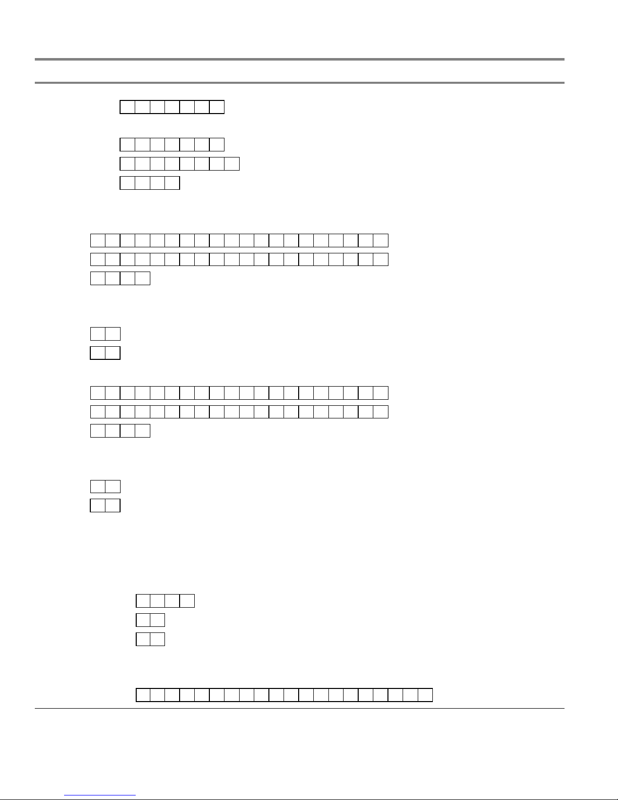
Programming templates
FSDACT programming worksheet
DACT setup
Access passcode (0 – 9, A – F) 1111111
Load defaults Yes No
Edit passcode (0 – 9, A – F)
Date (MMDDYYYY) 01012002
Time (HHMM) 0000
DACT mode Single line DACT Dual line DACT Modem/LCD LCD only
Receiver 1 (DACR1) Setup
Phone 1 Ex. 19415551212
Phone 2 Ex. 19415551212
Account (0 – 9, A – F) FFFF
Format Contact ID EST 4/2
Restores Send Restores No Restores
Retry Count (05 – 10) 05
Retry Time (05 – 10) 05
Receiver 2 (DACR2) Setup
Phone 1 Ex. 19415551212
Phone 2 Ex. 19415551212
Account (0 – 9, A – F) FFFF
Format Contact ID EST 4/2
Restores Send Restores No Restores
Retry Count (05 – 10) 05
Retry Time (05 – 10) 05
DACT Dialing Properties Setup
Tone/Pulse Line 1 Tone Pulse
Tone/Pulse Line 2 Tone Pulse
AC Fail Delay 6 Hours 15 Hours
Transmission Test Time (0000 – 2359) 0217
Transmission Test Freq. (00 – 02) 01
Rings to Answer (00 – 15) 05
Ring Type Ring type DACT answers any ring type after programmed ring count
Callback Enable No Yes
Callback Number
Note: Default settings are shown in boldface type.
B.2 FireShield Technical Reference Manual
Page 49

Programming templates
System event reporting setup
Event Where to report the event 4/2 event code
Panel test None CS 1 CS 2 CS 1 & 2 DF
Panel abnormal test None CS 1 CS 2 CS 1 & 2 6F
Walk test None CS 1 CS 2 CS 1 & 2 AF
Drill None CS 1 CS 2 CS 1 & 2 AD
Reset None CS 1 CS 2 CS 1 & 2 AB
Program mode None CS 1 CS 2 CS 1 & 2 C1
DACT Disabled None CS 1 CS 2 CS 1 & 2 AE
Panel silence None CS 1 CS 2 CS 1 & 2 CA
Signal silence None CS 1 CS 2 CS 1 & 2 AC
Ground fault None CS 1 CS 2 CS 1 & 2 66
Low battery None CS 1 CS 2 CS 1 & 2 6C
Missing battery None CS 1 CS 2 CS 1 & 2 6C
Internal comm trouble None CS 1 CS 2 CS 1 & 2 AA
AC fail None CS 1 CS 2 CS 1 & 2 69
Charger trouble None CS 1 CS 2 CS 1 & 2 6B
Transformer 2 trouble None CS 1 CS 2 CS 1 & 2 6A
Aux power trouble None CS 1 CS 2 CS 1 & 2 65
Peripheral trouble None CS 1 CS 2 CS 1 & 2 6D
DACT line 1 trouble None CS 1 CS 2 CS 1 & 2 68
DACT line 2 trouble None CS 1 CS 2 CS 1 & 2 6E
DACT delivery trouble None CS 1 CS 2 CS 1 & 2 67
System trouble restoral (4/2 code) (0 – F) D
Zone settings - IDC 1
Note: For IDCs, program only those events that apply to the IDC zone type you specified on the “Panel programming worksheet.”
Event Where to report the event 4/2 event code
Alarm activation None CS 1 CS 2 CS 1 & 2 11
Waterflow activation None CS 1 CS 2 CS 1 & 2 21
Trouble activation None CS 1 CS 2 CS 1 & 2 71
Supervisory activation None CS 1 CS 2 CS 1 & 2 31
Monitor activation None CS 1 CS 2 CS 1 & 2 51
Zone settings - IDC 2
Event Where to report the event 4/2 event code
Alarm activation None CS 1 CS 2 CS 1 & 2 12
Waterflow activation None CS 1 CS 2 CS 1 & 2 22
Trouble activation None CS 1 CS 2 CS 1 & 2 72
Supervisory activation None CS 1 CS 2 CS 1 & 2 32
Monitor activation None CS 1 CS 2 CS 1 & 2 52
Zone settings - IDC 3
Event Where to report the event 4/2 event code
Alarm activation None CS 1 CS 2 CS 1 & 2 13
Waterflow activation None CS 1 CS 2 CS 1 & 2 23
Trouble activation None CS 1 CS 2 CS 1 & 2 73
Supervisory activation None CS 1 CS 2 CS 1 & 2 33
Monitor activation None CS 1 CS 2 CS 1 & 2 53
Note: Default settings are shown in boldface type.
FireShield Technical Reference Manual B.3
Page 50

Programming templates
Zone settings - IDC 4
Event Where to report the event 4/2 event code
Alarm activation None CS 1 CS 2 CS 1 & 2 14
Waterflow activation None CS 1 CS 2 CS 1 & 2 24
Trouble activation None CS 1 CS 2 CS 1 & 2 74
Supervisory activation None CS 1 CS 2 CS 1 & 2 34
Monitor activation None CS 1 CS 2 CS 1 & 2 54
Zone settings - IDC 5
Event Where to report the event 4/2 event code
Alarm activation None CS 1 CS 2 CS 1 & 2 15
Waterflow activation None CS 1 CS 2 CS 1 & 2 25
Trouble activation None CS 1 CS 2 CS 1 & 2 75
Supervisory activation None CS 1 CS 2 CS 1 & 2 35
Monitor activation None CS 1 CS 2 CS 1 & 2 55
Zone settings - IDC 6
Event Where to report the event 4/2 event code
Alarm activation None CS 1 CS 2 CS 1 & 2 16
Waterflow activation None CS 1 CS 2 CS 1 & 2 26
Trouble activation None CS 1 CS 2 CS 1 & 2 76
Supervisory activation None CS 1 CS 2 CS 1 & 2 36
Monitor activation None CS 1 CS 2 CS 1 & 2 56
Zone settings - IDC 7
Event Where to report the event 4/2 event code
Alarm activation None CS 1 CS 2 CS 1 & 2 17
Waterflow activation None CS 1 CS 2 CS 1 & 2 27
Trouble activation None CS 1 CS 2 CS 1 & 2 77
Supervisory activation None CS 1 CS 2 CS 1 & 2 37
Monitor activation None CS 1 CS 2 CS 1 & 2 57
Zone settings - IDC 8
Event Where to report the event 4/2 event code
Alarm activation None CS 1 CS 2 CS 1 & 2 18
Waterflow activation None CS 1 CS 2 CS 1 & 2 28
Trouble activation None CS 1 CS 2 CS 1 & 2 78
Supervisory activation None CS 1 CS 2 CS 1 & 2 38
Monitor activation None CS 1 CS 2 CS 1 & 2 58
Zone settings - IDC 9
Event Where to report the event 4/2 event code
Alarm activation None CS 1 CS 2 CS 1 & 2 19
Waterflow activation None CS 1 CS 2 CS 1 & 2 29
Trouble activation None CS 1 CS 2 CS 1 & 2 79
Supervisory activation None CS 1 CS 2 CS 1 & 2 39
Monitor activation None CS 1 CS 2 CS 1 & 2 59
Note: Default settings are shown in boldface type.
B.4 FireShield Technical Reference Manual
Page 51

Programming templates
Zone settings - IDC 10
Event Where to report the event 4/2 event code
Alarm activation None CS 1 CS 2 CS 1 & 2 1A
Waterflow activation None CS 1 CS 2 CS 1 & 2 2A
Trouble activation None CS 1 CS 2 CS 1 & 2 7A
Supervisory activation None CS 1 CS 2 CS 1 & 2 3A
Monitor activation None CS 1 CS 2 CS 1 & 2 5A
Zone restoral (4/2 code) (0 – F) E
NAC settings - NAC 1
Event Where to report the event 4/2 event code
Trouble activation None CS 1 CS 2 CS 1 & 2 61
NAC settings - NAC 2
Event Where to report the event 4/2 event code
Trouble activation None CS 1 CS 2 CS 1 & 2 62
NAC settings - NAC 3
Event Where to report the event 4/2 Event code
Trouble activation None CS 1 CS 2 CS 1 & 2 63
NAC settings - NAC 4
Event Where to report the event 4/2 event code
Trouble activation None CS 1 CS 2 CS 1 & 2 64
NAC Trouble restoral (4/2 code) (0 – F) D
Other FSDACT options
Note: These options can only be changed using the FireShield Configuration Utility.
Swinger shutdown (0 – 255) 000
Contact ID codes
Code Description Code Description
Note: Default settings are shown in boldface type.
FireShield Technical Reference Manual B.5
Page 52

Programming templates
Contact ID codes
Code Description Code Description
B.6 FireShield Technical Reference Manual
Page 53

Appendix C
Jumper settings and wiring diagrams
Three-zone panel
[2] [3] [5] [11]
EOLR
+
+
–
EOLR
+
–
–
+
+
–
[2] [3] [9] [11]
–
Class B (Style Y)
NOTIFICATION APPLIANCE CIRCUITS
JP1 wire loop [12]
Ωµ
Operating voltage: 24 Vfwr
Operating current: 1.5 A/circuit, 1.5 A total
Circuit impedance: 13 , 0.03 F, max
DACT/Dialer (optional)
DACT
Ω
4.7 k , 1/2 W (P/N EOL4.7)
EOLR:
connector
Ωµ
+
+
+
+
–
+
–
NAC1–
J2
NAC2+
NAC2–
NAC1+
–
IDC1–
IDC1+
IDC2+
PRG
Normal mode
Jumper Setting Description
C–C+24VOUT–
IDC2–
–
–
Ω
Break the wire run at
4.7 k , 1/2 W (P/N EOL4.7)
Class B (Style B)
Operating voltage: 16.3 - 25.7 Vdc
Operating current: 1.5 mA/circuit, max
Circuit impedance: 13 , 0.03 F, max
INITIATING DEVICE CIRCUITS
IDC3–
IDC3+
Programming mode
RECHARGEABLE BATTERY CIRCUIT
Voltage: 24 Vdc
Amp-hour capacity: 18 Ah maximum sealed
PRG
24VOUT+
EOLR:
CAUTION:
each field device to provide proper
connection supervision. Do not loop
wires under terminals.
12 Vdc
Battery
Standby batteries larger than 7 Ah must
12 Vdc
Note:
be installed in a BC-2 battery cabi net.
lead acid batteries only
BLACK
RED
E1
E2
IN
24VAC
EGND
Battery
Never replace fuse while circuit is energized.
The middle connection on the terminal block makes a
Replacement fuse must be of equivalent size and type.
WARNING:
L
LINE
5 A, 250 V, SLO-BLO
CAUTION:
mechanical connection to the chassis even with the ground wire removed.
N
NEUTRAL
EARTH GND
FireShield Technical Reference Manual C.1
(Littlefuse P/N 218005)
DETAIL A
[10]
[10]
[10]
Nonsupervised
Nonsupervised
Nonsupervised
Ωµ
POWER OUTPUT
13 , 0.03 F, max
REMOTE MODULE
1 A @ 30 Vdc, resistive
1 A @ 30 Vdc, resistive
1 A @ 30 Vdc, resistive
COMMON TROUBLE RELAY
COMMON ALARM RELAY
COMMON SUPERVISORY RELAY
See
DETAIL A
AUXILIARY/SMOKE
COMMUNICATION BUS
24 Vdc, nominal @ 500 mA
MAIN SUPPLY CIRCUIT
120 V, 60 Hz, 0.8 A or
from dedicated branch supply
230 V, 50/60 Hz, 0.4 A
Page 54

Jumper settings and wiring diagrams
REMOTE MODULE AND
REMOTE RELAY WIRING
[6]
C–
C+
24VDC+
24VDC–
SMOKE DETECTOR CIRCUIT
IDC1+
24VDC+
24VDC–
IDC1–
WAT ERFLOW / SUPERVISORY COMBINATION CIRCUIT
IDC1+
IDC1–
POWER
ALARM
SUP
TBL
GND FLT
SILENCE
LMPTST
TYPICAL FOUR- WIRE
4.7 k
1.1 k
Ω
SS SSWFWF
[2] [3] [7]
Ω
REMOTE
RELAY
MODULE
(RRM)
UL/ULC LISTED
EOL RELAY
(shown energized)
[4] [8]
3.6 k
Ω
NOTES
1 All wiring is power-limited except for AC power and battery wiring. All wiring
is supervised unless noted other wise.
[2] Class A wiring not supported
[3] Listed EOLRs must be installed as shown for proper supervision
[4] For UL installations use EOLR P/N EOL3.6-1.1 which includes one 1.1 k
(P/N EOL1.1) and one 3.6 k (P/N EOL3.6) resistor. For ULC installations
use EOL-P1 and select the 1.1 k and 3.6 k resistors.
[5] Marking indicates output signal polarity when the circuit is active. Polarity
reverses when the circuit is not active. Wire notification appliances
accordingly. Notification appliance polarity shown in active state.
Ω
ΩΩ
Ω
Keep power-limited wiring in the shaded
area and nonpower-limited wiring in the
unshaded area at all times.
[6] Requires continuous 24 Vdc from the AUX Power
terminals or a power-limited UL/ULC listed compatible
fire signaling power supply
[7] IDC circuits do not support alarm verification using four-
wire smokes. Requires resettable 24 V dc from AUX
Power term inals.
[8] Combination circuits consist of waterflow switches (WF)
and their associated valve tampers (SS).
[9] Automatic and manual ly activated alarm initiating
devices can be installed on the same IDC circuit
regardless of circuit type except for combination circuits
(option 6, setting 5 and 6)
[10] Relay circuits c an only be connected to power-limited
sources
[11] Installation limits under jurisdiction of local authority
[12] Refer to the
(P/N 3100353) for the topic "Installing the FSDACT."
FireShield Technical Reference Manual
C.2 FireShield Technical Reference Manual
Page 55

Five-zone panel
Jumper settings and wiring diagrams
[2] [3] [5 [11]
EOLR
+
+
–
EOLR
–
–
+
–
+
–
+
–
[2] [3] [9] [11]
+
–
INITIATING DEVICE CIRCUITS
BLACK
Class B (Style B) or Class A (Style D)
Operating voltage: 16.3 - 25.7 Vdc
Ωµ
Ω
4.7 k , 1/2 W (P/N EOL4.7)
Operating current: 1.5 mA/circuit, max
Circuit impedance: 13 , 0.03 F, max
EOLR:
Standby batteries larger than 7 Ah mus t
Note:
12 Vdc
Battery
12 Vdc
Battery
be installed in a BC-2 battery cabinet.
Ωµ
+
–
+
–
Break the wire run at each field
device to provide proper connection supervision.
Do not loop wires under terminals.
NOTIFICATION APPLIANCE CIRCUITS
CAUTION:
The panel does not indicate
when JP6A is missing. A shorted NAC circuit
may damage the equipment if NAC jumpers
are missing or set incorrectly.
CAUTION:
JP1 wire loop [12]
Ω
Class B (Style Y) or Class A (Style Z)
Operating voltage: 24 Vfwr
Operating current: 1.5 A /circuit, 2.5 A total
Circuit impedance: 13 , 0.03 F, max
EOLR: 4.7 k , 1/2 W (P/N EOL4.7)
NAC1–
TB2
DACT/Dialer (optional)
NAC1+
JP6A
Normal mode
NAC2–
JP1A
Programming mode
NAC2+
+
–++
–
+
–
+
–
+
–
IDC1–
IDC1+
TB3
PRG
NAC1 and NAC2 = Class B
NAC1 = Class A Out
NAC2 = Class A Return
IDC2–
IDC2+
IDC1 and IDC2 = Class B
IDC3–
IDC3+
JP3A & JP2A
IDC1 = Class A Out
IDC2 = Class A Return
IDC4–
IDC4+
IDC3 and IDC4 = Class B
IDC5–
IDC5+
JP4A & JP5A
IDC3 = Class A Out
IDC4 = Class A Return
RECHARGEABLE BATTERY CIRCUIT
Voltage: 24 Vdc
Amp-hour capacity: 18 Ah maximum sealed
lead acid batteries only
DACT
connector
TB5
Never replace fuse while circuit is energized.
The middle connection on the terminal block makes a
Replacement fuse must be of equivalent size and type.
WARNING:
mechanical connection to the chassis even with the ground wire removed.
CAUTION:
5 A, 250 V, SLO-BLO
(Littlefuse P/N 218005)
L
N
LINE
DETAIL A
NEUTRAL
EARTH GND
PRG
Jumper Setting Description
J2
[10]
Nonsupervised
1 A @ 30 Vdc, resistive
COMMON TROUBLE RELAY
JP1A &JP6A
[10]
[10]
Nonsupervised
1 A @ 30 Vdc, resistive
1 A @ 30 Vdc, resistive
COMMON ALARM RELAY
COMMON SUPERVISORY RELAY
See
DETAIL A
C–C+24VOUT–
Nonsupervised
REMOTE MODULE
JP3A &JP2A
Ωµ
POWER OUTPUT
13 , 0.03 F, max
AUXILIARY/SMOKE
COMMUNICATION BUS
24VOUT+
24 Vdc,nominal @ 500 mA
JP4A &JP5A
MAIN SUPPLY CIRCUIT
120 V, 60 Hz, 0.8 A or
230 V, 50/60 Hz, 0.4 A
RED
E1
E2
TB1
IN
24VAC
EGND
from dedicated branch supply
FireShield Technical Reference Manual C.3
Page 56
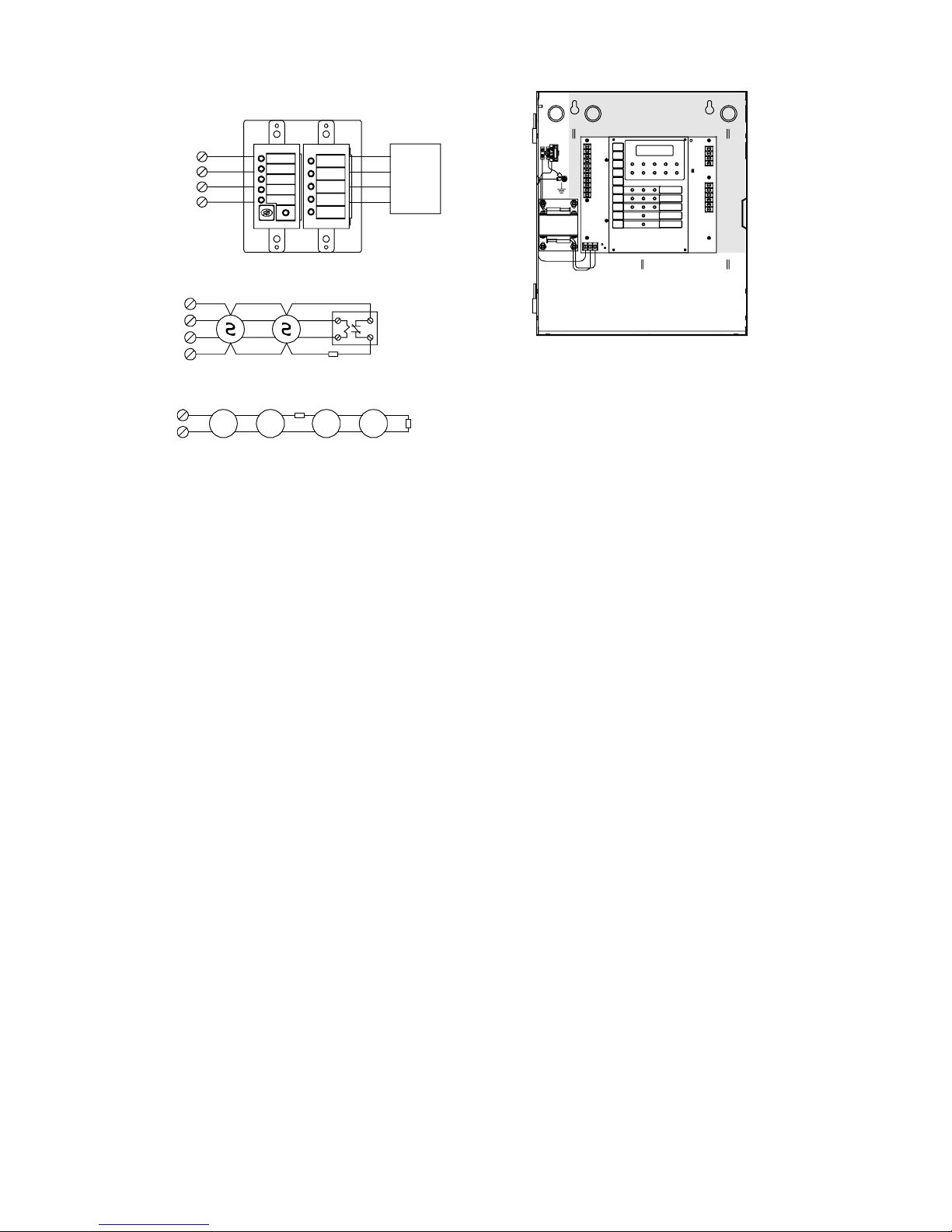
Jumper settings and wiring diagrams
REMOTE MODULE AND
REMOTE RELAY WIRING
[6]
C–
C+
24VDC+
24VDC–
SMOKE DETECTOR CIRCUIT
IDC1+
24VDC+
24VDC–
IDC1–
WAT ERFLOW / SUPERVISORY COMBINATION CIRCUIT
IDC1+
IDC1–
POWER
ALARM
SUP
TBL
GND FLT
SILENCE
LMPTST
TYPICAL FOUR- WIRE
4.7 k
1.1 k
Ω
SS SSWFWF
[2] [3] [7]
Ω
REMOTE
RELAY
MODULE
(RRM)
UL/ULC LISTED
EOL RELAY
(shown energized)
[4] [8]
3.6 k
Ω
NOTES
1 All wiring is power-limited except for AC power and battery wiring. All wiring
is supervised unless noted other wise.
[2] Class A wiring not supported
[3] Listed EOLRs must be installed as shown for proper supervision
[4] For UL installations use EOLR P/N EOL3.6-1.1 which includes one 1.1 k
(P/N EOL1.1) and one 3.6 k (P/N EOL3.6) resistor. For ULC installations
use EOL-P1 and select the 1.1 k and 3.6 k resistors.
[5] Marking indicates output signal polarity when the circuit is active. Polarity
reverses when the circuit is not active. Wire notification appliances
accordingly. Notification appliance polarity shown in active state.
Ω
ΩΩ
Ω
Keep power-limited wiring in the shaded
area and nonpower-limited wiring in the
unshaded area at all times.
[6] Requires continuous 24 Vdc from the AUX Power
terminals or a power-limited UL/ULC listed compatible
fire signaling power supply
[7] IDC circuits do not support alarm verification using four-
wire smokes. Requires resettable 24 V dc from AUX
Power term inals.
[8] Combination circuits consist of waterflow switches (WF)
and their associated valve tampers (SS).
[9] Automatic and manual ly activated alarm initiating
devices can be installed on the same IDC circuit
regardless of circuit type except for combination circuits
(option 6, setting 5 and 6)
[10] Relay circuits c an only be connected to power-limited
sources
[11] Installation limits under jurisdiction of local authority
[12] Refer to the
(P/N 3100353) for the topic "Installing the FSDACT."
FireShield Technical Reference Manual
C.4 FireShield Technical Reference Manual
Page 57

Ten-zone panel
[2] [3] [5] [8] [12]
Jumper settings and wiring diagrams
F, m ax
EOLR
µ
+
–
+
–
+
, 0.03
Ω
, 1/2 W (P/N EOL4. 7)
+
+
–
Ω
NAC1–
NAC2+
NAC2–
NOTIFICATION APPLIANCE C IRCUITS
Class B (Style Y) or Class A (Style Z)
Operating vol tage: 24 Vfwr
Operating cur rent: 1.5 A/circuit, 2.5 A total
NAC1+
Circuit impeda nce: 13
EOLR: 4.7 k
TB2
–
+
–
–
NAC3–
NAC4–
NAC3+
TB4
EOLR
+
–
+
–
+
–
+
–
+
–
+
–
+
–
+
–
+
+
–
IDC8–
+
IDC9+
–
–
IDC9–
+
–
+
NAC4+
+
–
+
–
+
–
+
–
+
–
+
–
+
IDC6–
IDC7+
–
IDC7–
IDC8+
–
IDC1–
IDC1+
IDC2–
IDC2+
IDC3–
IDC3+
IDC4–
IDC4+
IDC5–
IDC5+
TB5
IDC6+
TB6
[2] [3] [9] [12]
+
–
Ωµ
+
–
IDC10–
IDC10+
INITIATING DEVICE CIRCUITS
Ω
Break the wire run at each fiel d device to
EOLR: 4.7 k , 1/2 W (P/N EOL4.7)
CAUTION:
provide proper connection supervision.
Class B (Style B) or Class A (Style D)
Operating vol tage: 16.3 - 25.7 Vdc
Operating cur rent: 1.5 mA/cir cuit, max
Circuit impedance: 13 , 0.03 F
Do not loop wir es under terminals.
JP1
JP13
JP1 wire loop [13]
JP14
DACT/Dialer (optional)
The panel does n ot indicate w hen
DACT
connector
JP13 or JP14 are missing. A shorted NAC circuit
may damage the equipment if NAC jumpers are
missing or set incorrectly.
CAUTION:
J2
= B = A
PRG
Jumper Position D escri ption
PRG OFF Normal mode
JP6
NAC2 = Class A return
ON Programming mo de
A NAC1 = Class A out
JP1 & JP13 B NAC1 and N AC2 = Class B
JP3 & JP2
JP4 & JP 5
NAC4 = Class A return
IDC2 = Class A return
IDC4 = Class A return
A NAC3 = Class A out
A IDC1 = Class A out
A IDC3 = Class A out
JP6 & JP14 B NAC3 and N AC4 = Class B
JP2 & JP3 B IDC1 an d IDC2 = Class B
JP4 & JP5 B IDC3 an d IDC4 = Class B
JP7 & JP8
IDC6 = Class A return
A IDC5 = Class A out
JP7 & JP8 B IDC5 an d IDC6 = Class B
JP9 & JP10 B IDC7 and IDC8 = Class B
A IDC7 = Class A out
JP9 & JP 10
IDC8 = Class A return
IDC10 = Class A return
A IDC9 = Class A out
JP11 & JP12 B IDC9 and IDC10 = Class B
JP11 & JP12
12 Vd c
Battery
12 Vdc
Voltage: 24 Vdc
BLACK
Amp-hour capac ity: 18 Ah maximum sealed
lead acid batt eries only
RED
E1
E2
RECHARGEABLE BATTERY CIRCUIT
Battery
IN
EGND
C–C+24VOUT–
24VOUT+
TB3
[11]
[11]
[11]
Nonsupervised
Nonsupervised
1 A @ 30 Vdc, resistive
COMMON TROUBLE RELAY
COMMON SUPERVISORY RELAY
Nonsupervised
Ωµ
POWER OUTPUT
13 , 0.03 F, max
REMOTE MODULE
1 A @ 30 Vdc, resistive
1 A @ 30 Vdc, resistive
COMMON ALARM RELAY
COMMUNICATION BUS
AUXILIARY/SMOKE
24 Vdc,nominal @ 500 mA
The middle connection on the
CAUTION:
terminal block makes a mechani cal connecti on
to the chassis even with the ground wire removed.
Never replace
5A, 250V, SLO-BLO
(Littlefuse P/N 21800 5)
WAR NING:
fuse while c ircuit is energized.
Replacement fuse must be of
equivalent size and type.
L
N
LINE
NEUTRAL
EARTH GND
24VAC
TB1
DETAIL A
XTR3A120orXTR3A230
(OPTIONAL)
SEE DETAIL A
MAIN SUPPLY CIRCUIT
120 V, 60 Hz, 1.6 A
230 V, 50/60 Hz, 0.8 A
from dedicated branch suppl y
FireShield Technical Reference Manual C.5
Page 58

Jumper settings and wiring diagrams
REMOTE MODULE AND REMOTE RELAY WIRING
C–
C+
24VDC+
24VDC–
IDC1+
24VDC+
24VDC–
IDC1–
IDC2+
IDC2–
WATERFLOW / SUPERVISORY COMBINATION CIRCUIT
IDC1+
IDC1–
POWER
ALARM
SUP
TBL
GND FLT
SILENCE
LMPTST
TYPICAL FOUR- WIRE
SMOKE DETECTOR CIRCUIT
Ω
4.7 k
(Only Class B allowed)
1.1 k
Ω
SS SSWFWF
[2] [3] [7]
UL/ULC LISTED
(shown energized)
NOTES
1. All wiring is power-limited except for AC power and battery
wiring. All wiring is supervised unless otherwise noted.
[2] Dashed lines show Class A wiring
[3] Listed EOLRs must be installed as shown fo r proper
supervision. EOLRs are not required for Class A operation.
[4] For UL installat ions use EOLR P/N EOL3.6-1.1 which includes
one 1.1 k (P/N EOL1.1) and one 3.6 k (P/N EOL3.6)
ΩΩ
resistor. For ULC installations use EOL-P1 and select the 1.1
k an d 3.6 k resistors.
ΩΩ
[5] Marking indicates out put signal pol arity when the circuit is
active. Polarity reverses when the circuit is not active. Wire
notification appliances accordingly. Notification appliance
polarity shown in active state.
[6]
REMOTE
MODULE
EOL RELAY
[4] [10]
3.6 k
Ω
RELAY
(RRM)
[6] Requires continuous 24 Vdc from the AUX Power
terminals or a power-limited UL/ULC listed
compatible fire signaling power supply
[7] IDC circuits do not support alarm verification using
four-wire smokes. Requires resettable 24 Vdc from
AUX Power terminals.
[8] 5.0 A total with optional transformer (P/N XTR3A120
or XTR3A230
[9] Automatic and manually activated alarm i nitiating
devices can be installed on the same IDC circuit
regardless of circuit type except for combination
circuits (option 6, setting 5 and 6)
[10] Combination circuits consist of waterflow switches
(WF) and their associated valve tampers (SS)
[11] Relay circuits can only be connected to power-limited
sources
[12] I nstallation limits under jurisdiction of local authority
[13] Refer to the
(P/N 3100353) for the topic "Installing the FSDACT."
FireShie ld Technical Ref erence Manual
C.6 FireShield Technical Reference Manual
Page 59

Appendix D
Panel specifications
FS302 three-zone
panel
Class B 3 5 3 1 1086420Initiating device
circuits (IDCs)
Notification appliance
circuits (NACs)
Power supply 2.0 amps total 3.0 amps total 3.0 amps (expandable to 5.5 amps)
NAC voltage rating 24 Vfwr
Maximum NAC current 1.5 amps each
AC input
Base panel current draw (standby) 110 mA 120 mA 145 mA
Base panel current draw (alarm) 145 mA 170 mA 250 mA
Battery placement
Maximum auxiliary current 0.5 amps (may be programmed as resetable)
Auxiliary output 19 to 25.7 Vdc
IDC max. detector standby current
IDC circuit
IDC operating voltage 16.3 to 25.7 Vdc
Compatibility ID 100
Alarm contact Form A N.O. 30 Vdc @ 1 A (resistive load)
Trouble contact Form C 30 Vdc @ 1 A (resistive load)
Supervisory contact Form A N.O. 30 Vdc @ 1 A (resistive load)
Environmental
Terminal rating All terminals rated for 12 to18 AWG (0.75 to 2.5 sq mm)
Serial communications
Batteries Batteries must be sealed lead acid type only. Maximum charging capacity = 18 Ah.
120 Vac 60 Hz 0.8 amps 0.8 amps 1.6 amps - incl. optional exp. transformer
230 Vac 50/60 Hz 0.4 amps 0.4 amps 0.8 - incl. optional exp. transformer
Class A 0 0 1 2 012345
Class B 2 2 0 4 2 0
Class A 0 0 1 0 1 2
1.5 amps total
Up to two 7 Ah batteries will fit in the panel.
Note: If batteries greater than 7 Ah are required,
you must use the BC-2 battery cabinet. Refer to
installation sheet P/N 3100027.
1.5 mA (See FireShield UL and ULC Compatibility List (P/N 3100468)
Asynchronous communications maximum resistance: 13 Ω
FS502 five-zone panel FS1004 ten-zone panel
1.5 amps each
2.5 amps total
for maximum quantity of detectors per circuit.)
Maximum loop resistance: 13 Ω
Maximum loop capacitance: 0.03 µF
Temperature: 0 to 49 °C (32 to 120 °F)
Humidity: 5 to 93% RH, noncondensing
Maximum capacitance: 0.03 µF
1.5 amps each - 2.5 amps total for
NAC1 + NAC2 or NAC3 + NAC4
5.0 amps with optional
expander transformer
Up to two 18 Ah batteries will fit in the
panel.
FireShield Technical Reference Manual D.1
Page 60

Panel specifications
D.2 FireShield Technical Reference Manual
Page 61

Appendix E
Default event codes
Default Contact ID event codes
Code Description
Fire alarm – general
11000001
11000002
11000003
11000004
11000005
11000006
11000007
11000008
11000009
11000010
Fire alarm – waterflow (sprinkler)
11300001
11300002
11300003
11300004
11300005
11300006
11300007
11300008
11300009
11300010
Fire alarm – bypass
57000001
57000002
57000003
57000004
57000005
57000006
57000007
57000008
57000009
57000010
Supervisory – general
20000001
20000002
20000003
20000004
20000005
20000006
20000007
20000008
20000009
20000010
Fire IDC 1
Fire IDC 2
Fire IDC 3
Fire IDC 4
Fire IDC 5
Fire IDC 6
Fire IDC 7
Fire IDC 8
Fire IDC 9
Fire IDC10
Waterflow IDC 1
Waterflow IDC 2
Waterflow IDC 3
Waterflow IDC 4
Waterflow IDC 5
Waterflow IDC 6
Waterflow IDC 7
Waterflow IDC 8
Waterflow IDC 9
Waterflow IDC 10
Fire bypass IDC 1
Fire bypass IDC 2
Fire bypass IDC 3
Fire bypass IDC 4
Fire bypass IDC 5
Fire bypass IDC 6
Fire bypass IDC 7
Fire bypass IDC 8
Fire bypass IDC 9
Fire bypass IDC 10
Fire supervisory IDC 1
Fire supervisory IDC 2
Fire supervisory IDC 3
Fire supervisory IDC 4
Fire supervisory IDC 5
Fire supervisory IDC 6
Fire supervisory IDC 7
Fire supervisory IDC 8
Fire supervisory IDC 9
Fire supervisory IDC 10
Trouble – zone
37300001
37300002
37300003
37300004
37300005
37300006
37300007
37300008
37300009
37300010
Monitor point/zone – active
14000001
14000002
14000003
14000004
14000005
14000006
14000007
14000008
14000009
14000010
NAC – trouble
32000001
32000002
32000003
32000004
NAC – bypass
52000001
52000002
52000003
52000004
System events
30100000
30100000
30200000
30500000
30800000
30900000
31000000
31100000
31200000
31500000
32800000
33000000
35100000
35200000
35400000
53000000
55100000
60100000
60200000
60700000
60800000
62700000
62800000
Fire trouble (380 Sensor trouble) IDC 1
Fire trouble (380 Sensor trouble) IDC 2
Fire trouble (380 Sensor trouble) IDC 3
Fire trouble (380 Sensor trouble) IDC 4
Fire trouble (380 Sensor trouble) IDC 5
Fire trouble (380 Sensor trouble) IDC 6
Fire trouble (380 Sensor trouble) IDC 7
Fire trouble (380 Sensor trouble) IDC 8
Fire trouble (380 Sensor trouble) IDC 9
Fire trouble (380 Sensor trouble) IDC 10
General alarm IDC 1
General alarm IDC 2
General alarm IDC 3
General alarm IDC 4
General alarm IDC 5
General alarm IDC 6
General alarm IDC 7
General alarm IDC 8
General alarm IDC 9
General alarm IDC 10
Trouble NAC 1
Trouble NAC 2
Trouble NAC 3
Trouble NAC 4
Bypass NAC 1
Bypass NAC 2
Bypass NAC 3
Bypass NAC 4
AC failure
Transformer 2 trouble
Battery bad
Reset
Internal communications fault
Charger trouble
Ground fault
Battery missing
Auxiliary power trouble
Panel silence
Signal silence
Peripheral trouble
DACT line 1 trouble
DACT line 2 trouble
DACT delivery trouble
RRM bypass
DACT disabled
Drill
Panel test
Walk test
Panel abnormal test
Program mode entry
Program mode exit
FireShield Technical Reference Manual E.1
Page 62

Default event codes
Default (4/2) event codes
Code Description
1<N> Fire alarm activation events
2<N> Waterflow alarm activation events
3<N> Supervisory signal activation events
4 Not used
5<N> Monitor signal activation events
6<N:1-4> NAC trouble activation events
65 Aux power trouble activation
66 Ground fault activation
67 DACT delivery trouble
68 DACT line 1fail
69 AC loss
6A Transformer 2 trouble
6B Charger trouble
6C Battery missing/Battery bad
6D FSRSI, FSRZI, FSRRM trouble
6E DACT line 2 fail
6F DACT abnormal test
7<N> IDC trouble activation
8<N> IDC disabled (not configurable)
9<N> IDC enabled (not configurable)
A<N:1-4> NAC disabled (not configurable)
A5 FSRRM outputs disabled (not configurable)
AA Internal communication trouble
AB Panel reset
AC Signal silence activated
AD Drill activated
AE DACT disabled
AF Walk test activated
B<N:1-4> NAC enabled (not configurable)
B5 FSRRM outputs enabled (not configurable)
BB Panel reset restore (not configurable)
BC Signal silence ended (not configurable)
BD Drill ended (not configurable)
BE DACT enabled (not configurable)
BF Walk test ended (not configurable)
C1 Program mode entry
C2 Program mode exit (not configurable)
CA Panel silence activated
D<N:1-4> NAC trouble restoration
D5 Aux power trouble restoration
D6 Ground fault restoration
D7 DACT delivery trouble restore
D8 DACT line 1 restoration
D9 AC loss restoration
DA Transformer 2 restoration
DB Charger trouble restoration
DC Battery missing/Battery bad restore
DD FSRSI, FSRZI, FSRRM restoration
DE DACT line 2 restoration
DF DACT normal test
E<N> Fire alarm restoration
E<N> Waterflow alarm restoration
Code Description
E<N> Supervisory restoration
E<N> Monitor restoration
F<N> IDC trouble restoration
Note: N is the circuit number.
E.2 FireShield Technical Reference Manual
Page 63

Z
Index
4
4/2 event codes • E.2
A
alarm
IDC zone type • 3.4
LED • 1.2
resounding an alarm condition • 1.4
signal silenced LED • 1.2
annunciator trouble LED • 1.2
auto NAC silence timer
description • 3.3
operation • 1.4
programming • 3.3
aux power reset
description • 3.4
programming • 3.4
auxiliary power supply
installing • 2.12
B
battery calculation • A.1
battery trouble LED • 1.2
binary numbers
LEDs • 3.1
buttons
disable IDC • 1.2
disable NAC • 1.2
operating mode • 1.1
programming mode • 1.1, 3.1
buzzer
FSRSI • 2.2
silencing FSRSI buzzer • 1.4
silencing panel buzzer • 1.4
C
cabinet
dimensions • 2.1
installing • 2.1
MFC-A • 2.6
semi-flush mount • 2.1
surface mount • 2.1
calculations
battery • A.1
NAC maximum wire length • A.4
NAC voltage drop • A.3
checklist
installation checklist • 2.1
class A
programming • 3.5, 3.6
wiring • C.1, C.3, C.5
class B
programming • 3.5, 3.6
wiring • C.1, C.3, C.5
command options
FSRRM • 2.5
component descriptions • 1.3
contact ID codes • E.1
CTM
description • 2.11
installing • 2.11
wiring • 2.11
D
default event codes
FSDACT • E.1
defaults
factory defaults • 3.2
reloading the factory defaults • 3.2
disable
IDC • 1.2, 1.5
LED • 1.2
NAC • 1.2, 1.5
disabled events • 3.15
drill
drill button • 1.2
using the drill command • 1.5
E
enable
re-enable IDC or NAC • 1.5
enclosure • See cabinet
event notification programming
FSDACT • 3.14
F
find peripherals
description • 3.3
programming • 3.3
FireShield Configuration Utility • 3.1
FSCU • 3.1
FSDACT • 1.3
4/2 event codes • E.2
changing password • 3.9
contact ID • E.1
default event codes • E.1
description • 2.8
digit descriptions • 3.8
display • 3.1
editing programed information • 3.17
event notification programming • 3.14
getting started (programming) • 3.8
installing • 2.8
panel programming • 3.2
password • 3.9
programming • 3.7, 3.8, 3.9
programming buttons • 3.8
FSRPM
description • 2.10
installing • 2.10
wiring • 2.10
FSRRM
command options • 2.5
description • 2.5
installation instructions • 2.6
jumper setup • 2.5
MFC-A • 2.6
service and troubleshooting • 2.6
specifications • 2.5
wiring • 2.6
FSRSI
buzzer • 1.4, 2.2
description • 2.2
installation instructions • 2.2
jumper setup • 2.2
lamp test • 1.6
FireShield Technical Reference Manual Z.1
Page 64

Index
LEDs • 2.2
specifications • 2.2
wiring • 2.3
FSRZI-A
description • 2.3
installation instructions • 2.4
jumper setup • 2.4
lamp test • 1.6
LEDs • 2.3
specifications • 2.3
wiring • 2.4
G
ground and open tests • 4.1
ground fault LED • 1.2
I
IDC
alarm LED • 1.2
disable • 1.5
disable button • 1.2
programming class A or class B • 3.5
programming zone types • 3.4
re-enabling • 1.5
supervisory/monitor LED • 1.2
IDC disabled event • 3.15
IDC trouble LED • 1.2
initiating device circuit • See IDC
inputs
IDC zone types • 3.4
installation
checklist • 2.1
installing
auxiliary power supply • 2.12
cabinet • 2.1
CTM • 2.11
FSDACT • 2.8
FSRPM • 2.10
FSRRM • 2.5
FSRSI • 2.2
FSRZI-A • 2.3
metal dead front • 2.12
power expander transformer • 2.7
J
jumper
10-zone panel settings • C.5
3-zone panel settings • C.1
5-zone panel settings • C.3
FSRRM • 2.5
FSRSI • 2.2
FSRZI-A • 2.4
program jumper • 1.3, C.1, C.3, C.5
L
lamp test • 1.1
conducting a panel lamp test • 1.6
conducting an FSRSI and FSRZI-A lamp test • 1.6
LEDs
binary number value • 3.1
FSRSI • 2.2
FSRZI-A • 2.3
programming • 3.1
system • 1.2
load defaults
description • 3.3, 3.9
programming • 3.3, 3.9
M
maintenance • 4.1
metal dead front
installing • 2.12
MFC-A
FSRRM • 2.6
monitor
IDC zone type • 3.4
LED • 1.2
N
NAC
disable • 1.5
disable button • 1.2
maximum wire length • A.4
programming class A or class B • 3.6
programming outputs • 3.6
programming silence inhibit timer • 3.4
programming silenceable • 3.6
re-enabling • 1.5
silencing • 1.4
trouble LED • 1.2
voltage drop calculation • A.3
NAC disabled event • 3.15
notification appliance circuit • See NAC
O
open and ground tests • 4.1
operation
operating the panel • 1.4
overview • 1.1
outputs
NAC outputs • 3.6
overview
operation • 1.1
system • 1.1
P
panel
silencing buzzer • 1.4
panel silence button
operating mode • 1.2
programming mode • 3.1
password
changing FSDACT • 3.9
FSDACT • 3.9
power expander transformer • 1.3
description • 2.7
installation instructions • 2.7
specifications • 2.7
wiring • 2.7
power LED • 1.2
program jumper • 1.3, C.1, C.3, C.5
program mode
exiting • 3.2
programming
auto NAC silence timer • 3.3
aux power reset • 3.4
buttons • 3.1
find peripherals • 3.3
FSCU • 3.1
FSDACT • 3.8, 3.9
IDC class • 3.5
IDC zone types • 3.4
installing jumper • 3.2
load defaults • 3.3, 3.9
NAC class • 3.6
Z.2 FireShield Technical Reference Manual
Page 65

Index
NAC output • 3.6
NAC silence inhibit timer • 3.4
NAC silenceable • 3.6
options • 3.2
overview • 3.1
templates • B.1
programming methods • 3.1
R
remote disconnect button
operating mode • 1.1
programming mode • 1.1, 3.1
remote relay module • See FSRRM
remote system indicator • See FSRSI
remote zone indicator • See FSRZI-A
reset button
operating mode • 1.2
programming mode • 1.2, 3.1
resetting the panel • 1.4
S
semi-flush mount
cabinet • 2.1
service and troubleshooting
FSRRM • 2.6
signal silence & drill button
alarm mode • 1.2
normal mode • 1.2
programming mode • 1.2, 3.1
silencing
FSRSI buzzer • 1.4
notification appliances • 1.4
panel buzzer • 1.4
specifications
FSRRM • 2.5
FSRSI • 2.2
FSRZI-A • 2.3
panel • D.1
power expander transformer • 2.7
supervisory
IDC zone type • 3.4
LED • 1.2
surface mount
cabinet • 2.1
T
tie wrap mounts • 1.3
trouble LED • 1.2
trouble silence button
programming mode • 1.2
U
ULC tests • 4.1
W
walk test
audible • 1.6
LED • 1.2
overview • 1.5
silent • 1.6
using the walk test command • 1.5
walk test button
operating mode • 1.1
programming mode • 1.1, 3.1
waterflow
IDC zone type • 3.4
wiring
10-zone panel • C.5
3-zone panel • C.1
5-zone panel • C.3
class A • C.1, C.3, C.5
class B • C.1, C.3, C.5
CTM • 2.11
FSRPM • 2.10
FSRRM • 2.6
FSRSI • 2.3
FSRZI-A • 2.4
NAC maximum wire length • A.4
power expander transformer • 2.7
FireShield Technical Reference Manual Z.3
Page 66

Index
Z.4 FireShield Technical Reference Manual
Page 67

Frame these instructions and mount on the wall next to the control panel.
FireShield Fire Alarm Control Panel
Operating Instructions
For additional information, refer to the FireShield
Technical Reference Manual P/N 3100353.
RESPONDING TO ALARM SIGNALS
1. Evacuate the area.
2. Notify the proper authorities immediately and state
the nature and location of the emergency.
3. Be prepared to provide directions to firefighters when
they arrive.
TO SILENCE ALARM NOTIFICATION SIGNALS
WARNING! Alarm notification signals should not be
silenced until after all occupants have been evacuated.
1. Press Signal Silence & Drill.
The Signal Silenced LED turns on and all audible
notification circuits turn off. New alarm events turn the
notification circuits back on.
Note: Panel programming may delay alarm silence for up
to one minute, may prevent alarm silencing when water
flows through the sprinkler system, and may not turn off
visible notification circuits.
TO RETURN THE SYSTEM TO NORMAL AFTER AN
ALARM OR SUPERVISORY EVENT
1. Make sure all smoke detectors are free from smoke
and all manual pull stations are reset.
2. Press Reset.
Note: Panel programming may delay panel reset for up to
one minute after alarm notification circuits turn on.
TO INITIATE A FIRE DRILL
1. Press Signal Silence & Drill.
All audible notification circuits turn on. This function will
not automatically notify the fire department.
TO PERFORM A LAMP TEST (panel and remote
annunciators)
1.
Press and hold the Remote Disconnect and Walk
Test buttons simultaneously.
TO SILENCE THE PANEL BUZZER
1. Press Panel Silence.
The buzzer turns off. Any new events turn the buzzer
back on. Trouble conditions not cleared resound the
buzzer after a predetermined time.
WARNING! Trouble conditions may affect the panel's
ability to provide early detection and indication of a fire.
Clear trouble conditions immediately.
RESPONDING TO SUPERVISORY SIGNALS
1. Silence the panel buzzer.
2. Investigate the cause of the supervisory signal and
notify the authorized service personnel immediately.
RESPONDING TO MONITOR SIGNALS
1. Silence the panel buzzer.
2. Investigate the cause of the monitor signal and notify
the authorized service personnel immediately.
PERIODIC TEST RECOMMENDATIONS
See “Maintenance,” in the FireShield Technical
Reference Manual for test instructions and references.
Installed by
Name:
Company:
Address:
Phone:
Per NFPA 72
Protected Premises Fire Alarm System, Local
Auxiliary Fire Alarm System
Remote Supervising Station Fire Alarm System
Central Station
Date:
TO PERFORM A REMOTE ANNUNCIATOR LAMP
TEST
1.
Press and hold the Silence button on the RSI for
five seconds.
2. LEDs on remote annunciators will remain on until
silence button is released.
RESPONDING TO TROUBLE SIGNALS
1. Silence the panel buzzer.
2. Investigate the cause of the trouble and notify the
authorized service personnel immediately.
Operating Instruction Placard P/N: 3100470 REV: 2.0
FireShield - Fire Alarm Control Panel 1 / 1
For service contact
Company:
Address:
Phone:
Acceptance Inspection by
Date:
Page 68

 Loading...