

GE Security DFAMMD01-RX, DFAMMD01-TX, DFAMMD04-RX, DFAMMD04-TX, DFAMMF01-RX User Manual
...Page 1

Installation/Operation Instructions
DFAMMF01-TX/RX
DFASMF01-TX/RX
DFASMLF01-TX/RX
DFAMMD01-TX/RX
DFASMD01-TX/RX
DFASMLD01-TX/RX
DFAMMF04-TX/RX
DFASMF04-TX/RX
DFASMLF04-TX/RX
DFAMMD04-TX/RX
DFASMD04-TX/RX
DFASMLD04-TX/RX
Page 1/ 9
Page 2
Literature Part number
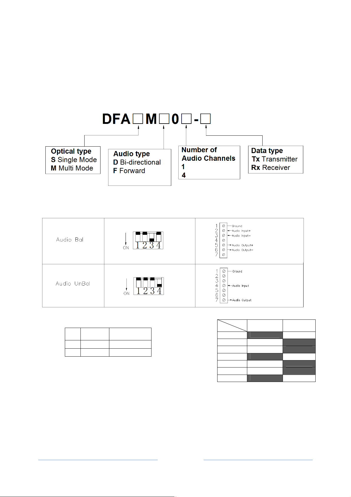
Dip switch setting and pin connections
Audio type
SW Balance Un-Balance
3 ON OFF
4 OFF ON
SW1 & SW2 are not applicable in this model
Page 2/ 9
Audio type
PIN
1 Ground Ground
2 Audio Input+ N/C
3 Audio Input- N/C
4 N/C Audio Input+
5 Audio Input+ N/C
6 Audio Input- N/C
7 N/C Audio Input-
*N/C: No connection
Balance Un-Balance
Page 3
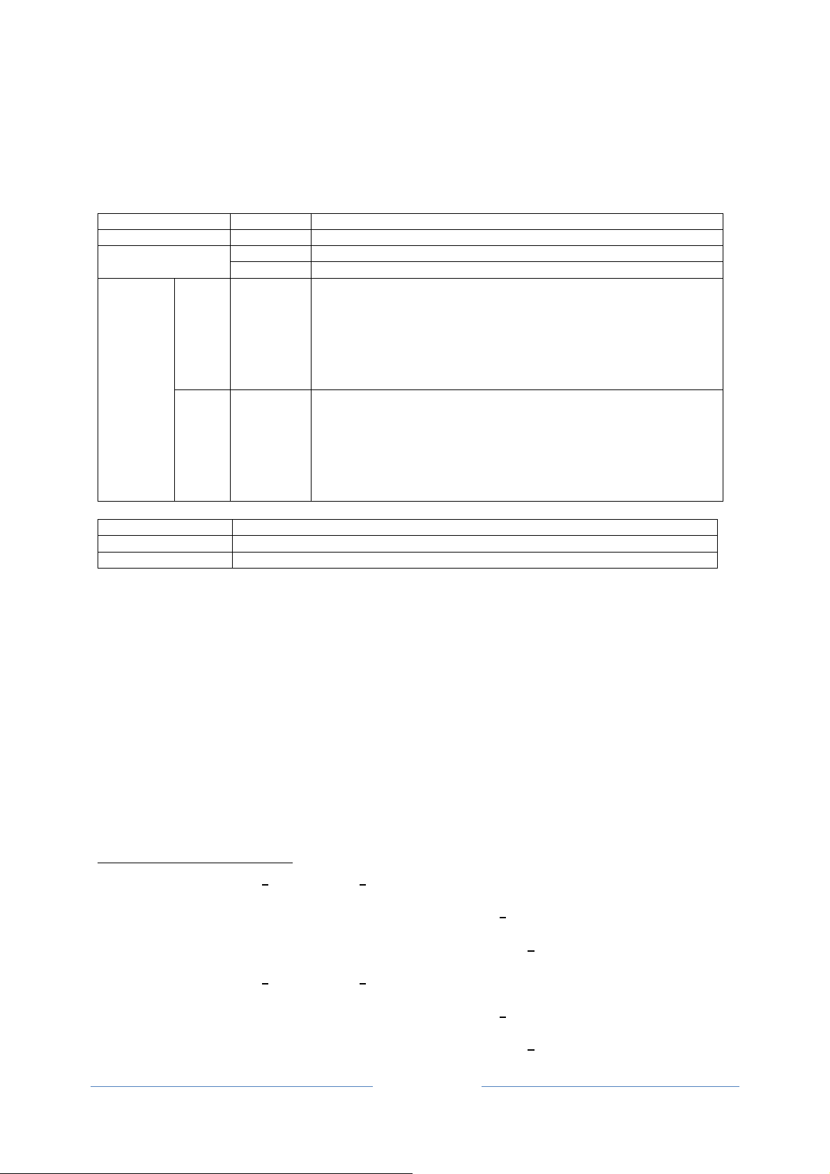
Transmitter
LED Indicators
Indicator Color Description
PWR Red Lit when power is supplied to the Transmitter.
Red Lit when fiber is not connected or without proper fiber connection. OL
Green1 Lit when optical signal from receiver to transmitter is active.
IN Green
AUDIO2
AUDIO13
AUDIO2
AUDIO3
AUDIO4
OUT4 Green
Signal Ports
OPT - ST (or FC) Optical Connector for fiber cable connection.
AUDIO5 - 7-pin Screw Terminal Block for audio signal.
AUDIO1-46- 7-pin Screw Terminal Block for audio signal.
At front panel: Blinks when forward input audio is available at Tx.
At rear panel:
a) Each audio channel has a single column of Four LEDs
assigned for displaying the input or output audio levels.
b) The LEDs (Input/Output) are lit in proportion to the signal
strength.
At front panel: Blinks when reverse output audio is available at
Tx.
At rear panel:
a) Each audio channel has a single column of Four LEDs
assigned for displaying the input or output audio levels.
b) The LEDs (Input/Output) are lit in proportion to the signal
strength.
1
Not available for the DFAMF0-T (i.e. DFASMF01-T)
2
AUDIO is only for the products with ONE audio channels (i.e. DFASMD01-T)
3
AUDIO 1-4 is only for the products with FOUR audio channels (i.e. DFASMD04-T)
4
Not available for the DFAMF0-T (i.e. DFASMF01-T)
5
AUDIO is only for the products with ONE audio channels (i.e. DFASMD01-T)
6
AUDIO 1-4 is only for the products with FOUR audio channels (i.e. DFASMD04-T)
Page 3/ 9
Page 4

Receiver
LED Indicators
Indicator Color Description
PWR Red Lit when power is supplied to the Receiver.
OL
AUDIO7
AUDIO18
AUDIO2
AUDIO3
AUDIO4
Signal Ports
OPT - ST (or FC) Optical Connector for fiber cable connection.
AUDIO10 - 7-pin Screw Terminal Block for audio signal.
AUDIO1-411- 7-pin Screw Terminal Block for audio signal.
IN9
OUT
Red Lit when fiber is not connected or without proper fiber connection.
Green Lit when optical signal from transmitter to receiver is active.
At front panel: Blinks when forward input audio is available at Rx.
At rear panel:
Green
Green
a) Each audio channel has a single column of Four LEDs assigned
for displaying the input or output audio levels.
b) The LEDs (Input/Output) are lit in proportion to the signal
strength.
At front panel: Blinks when reverse output audio is available at Rx.
At rear panel:
a) Each audio channel has a single column of Four LEDs assigned
for displaying the input or output audio levels.
b) The LEDs (Input/Output) are lit in proportion to the signal
strength.
7
AUDIO is only for the products with ONE audio channels (i.e. DFASMD01-R)
8
AUDIO 1-4 is only for the products with FOUR audio channels (i.e. DFASMD04-R)
9
Not available for the DFAMF0-T (i.e. DFASMF01-R)
10
AUDIO is only for the products with ONE audio channels (i.e. DFASMD01-R)
11
AUDIO 1-4 is only for the products with FOUR audio channels (i.e. DFASMD04-R)
Page 4/ 9
Page 5

Front and rear panel for each module
Transmitter Receiver
DFCCSMF01-TX; DFCCSMLF01-TX; DFCCMMF01-TX DFCCSMF01-RX; DFCCSMLF01-RX; DFCCMMF01-RX
DFCCSMD01-TX; DFCCSMLD01-TX; DFCCMMD01-TX DFCCSMD01-RX; DFCCSMLD01-RX; DFCCMMD01-RX
DFCCSMF04-TX; DFCCSMLF04-TX; DFCCMMF04-TX DFCCSMF04-RX; DFCCSMLF04-RX; DFCCMMF04-RX
DFCCSMD04-TX; DFCCSMLD04-TX; DFCCMMD04-TX DFCCSMD04-RX; DFCCSMLD04-RX; DFCCMMD04-RX
Page 5/ 9
Page 6

Fiber connection
Page 6/ 9
Page 7

Cable connection of DFASMD04-TX/RX, DFASMLD04-TX/RX & DFAMMD04-TX/RX
DFCCSMD04-TX DFCCSMD04-RX
DFCCSMLD04-TX DFCCSMLD04-RX
DFCCMMD04-TX DFCCMMD04-RX
This product is intended to be supplied by a UL Listed Direct Plug-In Power Unit marked "Class 2" or "LPS"
and output rated 12 VDC, 1 Amp minimum.
Page 7/ 9
Page 8

FCC Compliance
This device complies with Part 15 of the Federal Communications Commission (FCC) Rules.
Operation is subject to the following two conditions:
1.
This device may not cause harmful interference.
2.
This device must accept any interference received, including interference that may cause
undesired operation.
Changes or modifications not expressly approved by General Electric Company could void the
user’s authority to operate the equipment
NOTE: This equipment has been tested and found to comply with the limits for a Class A digital
device, pursuant to Part 15 of the FCC Rules. These limits are designed to provide reasonable
protection against harmful interference when the equipment is operated in a commercial
environment. This equipment generates, uses and can radiate radio frequency energy and, if not
installed and used in accordance with the instructions manual, may cause harmful interference to
radio communications. Operation of this equipment in a residential area is likely to cause
harmful interference in which case the user will be required to correct the interference at his own
expense.
CLASS 1 LASER PRODUCT
(For purposes of IEC 60825-1)
Complies with FDA Performance Standard for Laser Products
Title 21
Code of Federal Regulations Subchapter J
Comprehensive
Lifetime Warranty
Page 8/ 9
Page 9

Product Disassembly Instructions for WEEE
Per European Directive 2002/95/EC Waste Electrical and Electronic Equipment
Required Tools:
Phillips (cross-tip) screwdrivers.
For the enclosed box version and rack version:
1. Locate and remove box cover securement screws. Usually, but not limited to, at least 4
screws.
2. Lift off the front/ rear panel.
3. Locate and remove securement screws for printed circuit board (at bottom).
4. Slide out the printed circuit board.
5. If there are multiple boards to the assembly, continue removing securement screws unit
none are left.
6. Lift off printed circuit board.
7. Disassembly of box version of product is complete.
Page 9/ 9
 Loading...