

Page 1

imagination at work
GE
Security
1052xxx
.
.
CS875-575-375-275-175
Alarm system
Installers Manual
with CS5500 keypad
Page 2

We declare under our sole responsibility that this product is in conformity with Directive 93/68/EEC (Marking) and/or complies to the essential
requirements and all other relevant provisions of the 1999/5/EC (R&TTE) based on test results using (non)harmonized standards in accordance
with the Directives mentioned.
www.gesecurity.com
Copyright
(c) 2005 GE Security B.V.. All rights reserved. GE Security B.V. grants the right to reprint this manual for internal use only. GE Security B.V. reserves the right to change
information without notice.
Signature of representative/manufacturer: Raoul van Bergen
Manager Control & Communication GE Interlogix B.V.
Kelvinstraat 7
………………………….. 6003 DH Weert
The Netherlands
Place : Weert
Date : 9 December 2003
Page 1 of 2 Number: 02.42c
SECURITY LIFESAFETY COMMUNICATIONS
MANUFACTURERS
DECLARATION OF CONFORMITY
For
Product identification:
Model/type : CS575 series BOM revision level : see model listing
Category (description) : Alarm control panel
Brand : GE-InterlogiX/Aritech / Sentrol/ESL/ITI/Caddx/Casi Rusco/Kalatel
Manufacturer:
GE Interlogix
2008 Orchard Avenue
City West Business Campus
Naas Road,
Dublin 24
EU Representative:
GE Interlogix B.V.
Kelvinstraat 7
6003 DH Weert
The Netherlands
Concerning RTTE
EMC Safety Telecom
A sample of the product
has been tested by:
Compliance Engineering Ireland
Ltd.
RAYSTOWN, RATOATH ROAD,
ASHBOURNE, CO. MEATH, IRELAND
Interlogix Ireland Limited
Greenhills Centre,
Greenhills Road, Tallaght,
Dublin 24, IRELAND
Belcomlab
CE Qualification Plan: 02DUBCE5001-3 CS575
Test report reference
00E293-1 & 01E515-1 01DR575LV D-2 BCL/00-04
Applied standards
EN50130-4(1995) +A1(1998)
EN50081-1(1992)
EN55022(1994)
+A1(1995) +A2 (1997)
EN61000-3-2(1995) +A1(1995)
+A2(1998) +A14(2000)
EN61000-3-3(1995)
EN60950(2001) CTR21(1998)
+EG201121(1998)
Equipment class identifier (RF products falling under the scope of R&TTE)
X Not Applicable None (class 1 product)
(class 2 product)
Means of conformity
We declare under our sole responsibility that this product is in conformity with Directive 93/68/EEC (Marking) and/or
complies to the essential requirements and all other relevant provisions of the 1999/5/EC (R&TTE) based on test results
using (non)harmonized standards in accordance with the Directives mentioned
Signature of representative/manufacturer: Raoul van Bergen
Manager Control & Communication GE Interlogix B.V.
Kelvinstraat 7
………………………….. 6003 DH Weert
The Netherlands
Place : Weert
Date : 9 December 2003
Page 2 of 2 Number: 02.42c
Model listing (list of all product variants or models for which this declaration is valid)
Model Description BOM revision date
CS575 Control Panel 8 Zones Plastic
18-JUN-02
CS575M Control Panel 8 Zones Metal Hs
13-JUN-02
CS575S1 Control Panel 8 Zones Plastic
20-JUN-02
CS575S4 Control Panel 8 zones Varel
04-JUL-02
CS575S88 Control Panel 8 Securitas
21-MAR-02
CS575S88NTXF Control Panel 8 Securitas NO XFR
21-MAR-02
CS375 Control Panel 24 Zones
September 2003
CS375M Control Panel 24 Zones Metal
September 2003
CS575S88-NO Control Panel 8 Zones Securitas Norway
November 2003
CS575S88-SW Control Panel 8 Zones Securitas Sweden
December 2003
CS575S88-DK Control Panel 8 Zones Securitas Denmark
December 2003
CS575S88-BE Control Panel 8 Zones Belgacom
December 2003
RK575 Securitas Retrofit Solution
December 2003
CS375S88-BE Control Panel 16 Zones Belgacom
December 2003
CS375S88-SW Control Panel 16 Zones Securitas Sweden
December 2003
CS375S88-DK Control Panel 16 Zones Securitas Denmark
December 2003
CS375S88-NO Control Panel 16 Zones Securitas Norway
December 2003
Page 3

CS875-575-375-275-175 Installers Manual with CS5500 keypad i
Contents
Section A:
Installing and programming a basic system
1 Introducing the CSx75 system ................................................................................... A-1-1
1.1 Getting started..............................................................................................................A-1-1
1.1.1 Welcome.....................................................................................................................A-1-1
1.1.2 Default country codes.................................................................................................A-1-1
1.2 Keypads.......................................................................................................................A-1-1
1.2.1 CS5500 keypad..........................................................................................................A-1-1
1.2.2 Other LCD and LED keypads.....................................................................................A-1-3
2 Designing the CSx75 system...................................................................................... A-2-1
2.1 System versions...........................................................................................................A-2-1
2.2 Parts of the system ......................................................................................................A-2-2
3 Installation guidelines................................................................................................. A-3-1
3.1 Mains power connection ..............................................................................................A-3-1
3.2 Mounting ......................................................................................................................A-3-1
3.3 Cabling.........................................................................................................................A-3-1
3.3.1 Shielded and unshielded cable................................................................................... A-3-1
3.3.2 Twisted and untwisted cable.......................................................................................A-3-1
3.4 Wiring guidelines..........................................................................................................A-3-1
3.5 Defaulting the panel.....................................................................................................A-3-2
3.6 Using the DIP switch diagrams....................................................................................A-3-2
4 Installing a basic system ............................................................................................ A-4-1
4.1 Wiring zones ................................................................................................................A-4-1
4.1.1 General.......................................................................................................................A-4-1
4.1.2 Dual wiring..................................................................................................................A-4-1
4.1.3 Single wiring ...............................................................................................................A-4-1
4.2 Installing the control unit ..............................................................................................A-4-1
4.2.1 CS575M/CS875M (large metal housing)....................................................................A-4-2
4.2.2 CS275/CS375/CS575/CS875 (polycarbonate housing) ............................................A-4-4
4.2.3 CS175M/CS275M/CS375M/CS575SM (small metal housing) ...................................A-4-6
4.3 Installing the keypad ....................................................................................................A-4-8
4.3.1 Wiring the keypad.......................................................................................................A-4-8
4.3.2 Wiring several keypads together ................................................................................A-4-9
4.4 Wiring sounders.........................................................................................................A-4-11
4.4.1 Wiring a sounder with EOL protection......................................................................A-4-11
4.5 Wiring fire detectors ...................................................................................................A-4-13
4.5.1 4-wire fire detector (CS275-375-575-875)................................................................A-4-14
4.5.2 2-wire fire detector (CS275-375-575-875)...............................................................A-4-14
4.5.3 4-wire fire detector (CS175)......................................................................................A-4-15
4.6 Wiring the outputs......................................................................................................A-4-16
4.7 Control unit wiring diagrams.......................................................................................A-4-17
4.7.1 CS175......................................................................................................................A-4-17
4.7.2 CS275......................................................................................................................A-4-18
4.7.3 CS375, CS575 and CS875.......................................................................................A-4-19
5 Programming the system............................................................................................ A-5-1
5.1 Powering up the system...............................................................................................A-5-1
5.2 Entering programming mode........................................................................................A-5-1
5.2.1 Changing the user interface language........................................................................A-5-1
5.3 Navigating the menus ..................................................................................................A-5-1
5.3.1 Command menu.........................................................................................................A-5-1
5.4 Selecting a menu option ..............................................................................................A-5-2
5.5 Changing a menu option.............................................................................................. A-5-2
5.5.1 Changing selection list entries....................................................................................A-5-2
5.5.2 Changing binary entries..............................................................................................A-5-2
5.5.3 Changing numeric entries...........................................................................................A-5-2
5.5.4 Changing phone numbers and phone prefixes...........................................................A-5-3
5.6 Exiting the menu system..............................................................................................A-5-3
Page 4

CS875-575-375-275-175 Installers Manual with CS5500 keypad ii
5.7 Editing text ...................................................................................................................A-5-3
5.7.1 Overview.....................................................................................................................A-5-3
5.7.2 Example......................................................................................................................A-5-4
5.7.3 Word library................................................................................................................A-5-4
5.7.4 Installer message........................................................................................................A-5-5
6 Setting up a communicator ....................................................................................... A-6-1
6.1 Reporting......................................................................................................................A-6-1
0.0.1 Reporting to one phone number .................................................................................A-6-1
6.1.1 Backup reporting ........................................................................................................A-6-1
6.1.2 Dual reporting.............................................................................................................A-6-2
6.1.3 Split reporting..............................................................................................................A-6-2
Section B
Installing and programming the modules
1 Enrolling modules ...................................................................................................... B-1-1
1.1 Enrolling the system modules................................................................................................B-1-1
1.2 Defaulting the modules..........................................................................................................B-1-1
1.3 Glossary.................................................................................................................................B-1-1
2 Programming the control panel ................................................................................ B-2-1
2.1 Overview................................................................................................................................B-2-1
2.2 Programming inputs...............................................................................................................B-2-1
2.2.1 Defining a zone ...........................................................................................................B-2-2
2.2.2 Copying zone settings ................................................................................................B-2-2
2.2.3 Editing a zone type .....................................................................................................B-2-3
2.2.4 Setting swinger shutdown ...........................................................................................B-2-3
2.3 Programming outputs.............................................................................................................B-2-4
2.3.1 Configuring an output ..................................................................................................B-2-4
2.3.2 Configuring the internal siren.......................................................................................B-2-5
2.3.3 Programming the keypad sounder...............................................................................B-2-6
2.4 Assigning codes.....................................................................................................................B-2-6
2.4.1 Setting up the installer code........................................................................................B-2-6
2.5 Setting communication options..............................................................................................B-2-7
2.5.1 Defining communication with a central station.............................................................B-2-8
2.5.2 Defining communication with upload/download software ............................................B-2-8
2.5.3 Configuring the system autotest..................................................................................B-2-8
2.5.4 Enabling reporting........................................................................................................B-2-9
2.6 Configuring partitions.............................................................................................................B-2-9
2.6.1 Setting timers...............................................................................................................B-2-9
2.6.2 Configuring a partition................................................................................................B-2-10
2.7 Configuring the system........................................................................................................B-2-10
2.7.1 Setting timers.............................................................................................................B-2-11
2.7.2 Configuring system features......................................................................................B-2-11
2.8 Setting arm schedules .........................................................................................................B-2-11
2.8.1 Setting up schedules .................................................................................................B-2-11
2.9 Programming the system to work with a home automation system.....................................B-2-12
2.9.1 Enabling broadcasts..................................................................................................B-2-13
2.9.2 Enabling commands and requests............................................................................B-2-13
2.10 Glossary..................................................... ........................................................................B-2-14
2.11 Technical Specifications ....................................................................................................B-2-33
3 Programming the current keypads ........................................................................... B-3-1
3.1 Overview................................................................................................................................B-3-1
3.2 Configuring keypad features..................................................................................................B-3-1
3.3 Multi-area mode.....................................................................................................................B-3-2
3.4 Assigning X-10 devices..........................................................................................................B-3-2
3.5 Copying keypad settings........................................................................................................B-3-2
3.6 Configuring keypad text.........................................................................................................B-3-2
3.7 Setting the keypad partition and keypad number...................................................................B-3-3
3.8 Glossary.................................................................................................................................B-3-3
3.9 Technical specifications.........................................................................................................B-3-6
3.9.1 CS5006 LED keypad...................................................................................................B-3-6
3.9.2 CS5XX8 LED keypad, where XX is the country code..................................................B-3-6
3.9.3 CS5500 menu driven keypad ......................................................................................B-3-7
3.9.4 Keyswitch zones..........................................................................................................B-3-7
4 Programming the other keypads............................................................................... B-4-1
4.1 Glossary.................................................................................................................................B-4-1
Page 5

CS875-575-375-275-175 Installers Manual with CS5500 keypad iii
5 Setting up the RF receivers ....................................................................................... B-5-1
5.1 Overview................................................................................................................................B-5-1
5.1.1 Types of receivers .......................................................................................................B-5-1
5.2 Installing an RF433 Mhz receiver ..........................................................................................B-5-2
5.2.1 Wiring an RF433 Mhz receiver....................................................................................B-5-2
5.2.2 Setting the RF433 Mhz receiver DIP switches ............................................................B-5-2
5.2.3 RF433 Mhz receiver status conditions.........................................................................B-5-3
5.3 Installing an RF868 Mhz receiver ..........................................................................................B-5-4
5.3.1 Wiring an RF868 Mhz receiver....................................................................................B-5-4
5.3.2 Setting the RF868 Mhz receiver DIP switches ............................................................B-5-4
5.3.3 RF868 Mhz receiver status conditions.........................................................................B-5-5
5.4 Programming the RF system.................................................................................................B-5-6
5.4.1 Defaulting the wireless modules..................................................................................B-5-6
5.4.2 Programming the wireless detectors ...........................................................................B-5-6
5.4.3 Configuring receiver features.......................................................................................B-5-7
5.4.4 Setting supervision windows........................................................................................B-5-7
5.5 Testing wireless sensors........................................................................................................B-5-8
5.5.1 RF433 Mhz system......................................................................................................B-5-8
5.5.2 RF868 Mhz system......................................................................................................B-5-8
5.6 Deleting sensors....................................................................................................................B-5-8
5.7 Glossary.................................................................................................................................B-5-9
5.8 Technical specifications.......................................................................................................B-5-11
5.8.1 RF433 receivers: RX8i4-pcb, RX16i4-pcb, RX48i4-pcb............................................B-5-11
5.8.2 RF868 receivers: RX8w8-pcb, RX16w8-pcb, RX32w8-pcb.......................................B-5-11
5.8.3 Empty housing RXWEH00 (868 Mhz) and RXIEH00 (433 Mhz)...............................B-5-11
6 Setting up the CS208H / CS208 / CS216 ................................................................... B-6-1
6.1 Overview................................................................................................................................B-6-1
6.2 CS208 / CS216 input expander.............................................................................................B-6-1
6.1.4 Installing the CS208 / CS216 input expander.............................................................B-6-1
6.1.5 Setting the DIP switches.............................................................................................B-6-1
6.1.6 Wiring the CS208 / CS216 input expander.................................................................B-6-3
6.3 CS208H input expander.........................................................................................................B-6-4
6.1.7 Installing the CS208H input expander........................................................................B-6-4
6.1.8 CS208H input expander board...................................................................................B-6-4
6.1.9 Setting the DIP switches.............................................................................................B-6-5
6.1.10 Wiring the CS208H input expander..........................................................................B-6-6
6.4 Programming the CS208H / CS208 / CS216 input expander................................................B-6-6
6.5 Glossary.................................................................................................................................B-6-7
6.6 Technical specifications.........................................................................................................B-6-7
6.6.1 CS208 / CS216 input expander...................................................................................B-6-7
6.6.2 CS208H input expander ..............................................................................................B-6-7
7 Setting up the CS507.................................................................................................. B-7-1
7.1 Overview................................................................................................................................B-7-1
7.2 Installing the CS507 output expander....................................................................................B-7-1
7.2.1 Setting the DIP switches..............................................................................................B-7-2
7.2.2 Wiring the CS507 output expander..............................................................................B-7-2
7.3 Programming the CS507 output expander ............................................................................B-7-4
7.3.1 Setting up schedules ...................................................................................................B-7-6
7.3.2 Configuring an output ..................................................................................................B-7-6
7.3.3 Configuring users.........................................................................................................B-7-6
7.4 Glossary.................................................................................................................................B-7-7
7.5 Technical specifications.........................................................................................................B-7-9
8 Setting up the CS586.................................................................................................. B-8-1
8.1 Overview................................................................................................................................B-8-1
8.2 Connecting the CS586 direct connect module.......................................................................B-8-1
8.2.1 Connecting the CS586 to a PC ...................................................................................B-8-1
8.2.2 Connecting the CS586 to a PC and a panel ...............................................................B-8-2
8.2.3 Connecting the CS586 to a panel ...............................................................................B-8-2
8.3 Programming the CS586 direct connect module ..................................................................B-8-2
8.3.1 Enabling memory transfer using the CS5500 keypad .................................................B-8-3
8.3.2 Enabling memory transfer using UDx75 software .......................................................B-8-3
8.4 Glossary.................................................................................................................................B-8-4
8.5 Technical Specifications ........................................................................................................B-8-4
9 Setting up the CS534.................................................................................................. B-9-1
9.1 Overview................................................................................................................................B-9-1
Page 6

CS875-575-375-275-175 Installers Manual with CS5500 keypad iv
9.2 Installing the CS534 listen-in module.....................................................................................B-9-1
9.2.1 Wiring the CS534 listen-in module ..............................................................................B-9-2
9.2.2 General operating instructions.....................................................................................B-9-2
9.2.3 Control levels...............................................................................................................B-9-3
9.2.4 Tones...........................................................................................................................B-9-4
9.3 Programming the CS534 listen-in module.............................................................................B-9-5
9.3.1 Configuring listen-in options........................................................................................B-9-5
9.3.2 Programming timers....................................................................................................B-9-5
9.3.3 Setting volume levels...................................................................................................B-9-5
9.3.4 Assigning X-10 devices ...............................................................................................B-9-6
9.4 Glossary.................................................................................................................................B-9-6
9.5 Technical specifications.........................................................................................................B-9-8
10 Setting up the CS320.............................................................................................. B-10-1
10.1 Overview............................................................................................................................B-10-1
10.2 Installing the CS320 auxiliary power module.....................................................................B-10-1
10.2.1 Wiring the CS320 auxiliary power module...............................................................B-10-2
10.2.2 Setting the DIP switches............................................................ ... ... ........................B-10-2
10.2.3 Enrolling the CS320 auxiliary power module...........................................................B-10-3
10.3 Programming the CS320 auxiliary power module..............................................................B-10-3
10.3.1 Configuring outputs.................................................................................................B-10-3
10.3.2 Configuring features ................................................. ...............................................B-10-4
10.4 Glossary..................................................... ........................................................................B-10-5
10.5 Technical specification s.....................................................................................................B-10-7
11 Setting up the CS535.............................................................................................. B-11-1
11.1 Overview............................................................................................................................B-11-1
11.2 Installing the CS535 voice module.....................................................................................B-11-1
11.3 Programming the CS535 voice module.............................................................................B-11-2
11.3.1 Configuring the control panel for voice reporting.....................................................B-11-2
11.3.2 Recording voice messages......................................................................................B-11-2
11.3.3 Playing back messages...........................................................................................B-11-3
11.3.4 Configuring handshake and kiss off........................................ .................................B-11-3
11.4 Glossary..................................................... ........................................................................B-11-4
11.5 Technical specification s.....................................................................................................B-11-5
12 Setting up the CS1700............................................................................................ B-12-1
12.1 Overview............................................................................................................................B-12-1
12.2 Installing the CS1700 proximity reader..............................................................................B-12-1
12.2.1 Wiring the CS1700 proximity reader........................................................................B-12-2
12.2.2 Enrolling the CS1700 proximity reader....................................................................B-12-2
12.3 Programming the CS1700 proximity reader.......................................................................B-12-3
12.3.1 Programming badge functions.................................................................................B-12-3
12.3.2 Configuring X-10 functions......................................................................................B-12-4
12.3.3 Adding and deleting cards.......................................................................................B-12-4
12.4 Glossary..................................................... ........................................................................B-12-6
12.5 Technical specification s.....................................................................................................B-12-9
13 Setting up the CS7002............................................................................................ B-13-1
13.1 Overview............................................................................................................................B-13-1
13.2 Installing the CS7002 GPRS module................................................................................B-13-2
13.2.1 Enrol the SIM card on the GSM network........................ .........................................B-13-2
13.2.2 Inserting the SIM card..............................................................................................B-13-3
13.2.3 Wiring the CS7002 GPRS module...........................................................................B-13-3
13.2.4 Reporting LEDs ................................................ .......................................................B-13-3
13.3 Programming the CS7002 GPRS module .........................................................................B-13-4
13.3.1 Testing the RSSI value............................................................................................B-13-4
13.3.2 Reporting..................... ... ... ......................................................................................B-13-5
13.3.3 Using upload/download ............................................... ... .........................................B-13-6
13.4 Glossary..................................................... ........................................................................B-13-7
13.5 Technical specification s...................................................................................................B-13-13
14 Reserved.................................................................................................................. B-14-1
15 Setting up the CS7050............................................................................................ B-15-1
15.1 Overview............................................................................................................................B-15-1
15.2 Installing the CS7050 TCP/IP module ...............................................................................B-15-1
15.2.1 Wiring the CS7050 TCP/IP module .........................................................................B-15-2
15.2.2 LED indicators.................................... .....................................................................B-15-2
15.3 Programming the CS7050 TCP/IP module........................................................................B-15-3
15.3.1 Configuring TCP/IP reporting...................................................................................B-15-4
Page 7

CS875-575-375-275-175 Installers Manual with CS5500 keypad v
15.3.2 Configuring email reporting......................................................................................B-15-4
15.3.3 Configuring reporting options...................................................................................B-15-5
15.3.4 Configuring upload/download..................... .............................................................B-15-5
15.4 Glossary..................................................... ........................................................................B-15-7
15.5 Technical specification s...................................................................................................B-15-11
16 Setting up the CS7501............................................................................................ B-16-1
16.1 Overview............................................................................................................................B-16-1
16.2 Installing the CS7501 ISDN dialler ....................................................................................B-16-1
16.2.1 LED indicators.................................... .....................................................................B-16-2
16.2.2 Mounting the CS7501 ISDN dialler..........................................................................B-16-2
16.2.3 Wiring the battery leads...........................................................................................B-16-6
16.3 Programming the CS7501 ISDN dialler.............................................................................B-16-7
16.3.1 Configuring phone reporting....................................................................................B-16-7
16.3.2 Configuring AL2 supervised ISDN connection.........................................................B-16-8
16.3.3 Uploading and downloading ....................................................................................B-16-8
16.4 Glossary..................................................... ........................................................................B-16-9
16.5 Technical specification s...................................................................................................B-16-13
17 Reading the event log ............................................................................................ B-17-1
17.1 Overview............................................................................................................................B-17-1
17.2 Event log events ................................................................................................................B-17-2
17.3 Glossary..................................................... ........................................................................B-17-4
18 Programming with the UDx75 software................................................................ B-18-1
18.1 Other methods of programming.........................................................................................B-18-1
18.2 Connecting the panel to the computer...............................................................................B-18-1
18.2.1 Connecting using a serial port.................... .............................................................B-18-1
18.2.2 Connecting using a modem.....................................................................................B-18-1
18.3 Programming with upload/download software ...................................................................B-18-2
18.3.1 Programming tasks.............................................................. ....................................B-18-3
Section C
Reference
1 Appendices ..................................................................................................................C-1-1
1.1 Appendix 1: Reporting fixed codes in Contact ID or SIA...............................................C-1-1
1.2 Appendix 2: Overview of module numbers ...................................................................C-1-2
1.2.1 CS1700 door swipe module ........................................................................................C-1-2
1.2.2 Keypads.......................................................................................................................C-1-2
1.3 Appendix 3: Communicator formats..............................................................................C-1-3
1.4 Appendix 4: Service messages.....................................................................................C-1-3
1.5 Appendix 5: Tasks summary.........................................................................................C-1-6
1.6 Appendix 6: Word library words....................................................................................C-1-6
Page 8

Section A:
Installing and programming a
basic system
1 Introducing the CSx75 system .................................................................................................................................A-1-1
2 Designing the CSx75 system.....................................................................................................................................A-2-1
3 Installation guidelines...................................................................................................................................................A-3-1
4 Installing a basic system.............................................................................................................................................A-4-1
5 Programming the system...........................................................................................................................................A-5-1
6 Setting up a communicator.......................................................................................................................................A-6-1
Page 9

CS875-575-375-275-175 Installers Manual with CS5500 keypad A.1.1
Chapter 1: Introducing the CSx75 system
1.1 Getting started
1.1.1 Welcome
Welcome to the CSx75 system range. We hope that you find it a useful addition to our range of products.
The CSx75 system design allows a fully loaded system to be housed in one single metal or plastic enclosure. It
can be expanded as required with additional modules. Five different panel types are available: the CS175,
CS275, CS375, CS575 and CS875. In this manual they are known collectively as the CSx75.
This manual describes a CSx75 installation using the CS5500, the menu driven keypad. The CS5500 allows you
to program the system easily using a menu structure.
1.1.2 Default country codes
Table 1-1: Default country codes lists the default codes used in each country.
<
The brackets contain the additional digits for the 6-digit codes.
1.2 Keypads
1.2.1 CS5500 keypad
The CS5500 LCD keypad allows you to program the CSx75 system using a menu structure.
Table 1-1: Default country codes
Country Country
code
User code Installer code Download access code
Baltic states 03 1122 1278 12780000
France 02 1122(56) 1278(00) 84800000
Belgium 11 1122(56) 1278(00) 12780000
Czech Republic 20 1122 1278 12780000
Denmark 07 1122(00) 1278(00) 12780000
Finland 28 1122 1278 12780000
France 02 1122(56) 1278(00) 84800000
Germany 04 1122(56) 1278(00) 12780000
Hungary 22 1122 1278 12780000
Ireland 12 1122 1278 12780000
Italy 10 7777(77) 8522(22) 84800000
Netherlands 01 1122(56) 1278(00) 12780000
Norway 05 1122(00) 1278(00) 12780000
Poland 18 1122(56) 1278(00) 84800000
Portugal 21 1122(56) 1278(00) 84800000
Slovak Republic 24 1122 1278 12780000
Spain 09 1122(56) 1278(00) 84800000
Sweden 06 1122(00) 1278(00) 12780000
UK 03 1122 1278 12780000
Page 10

CS875-575-375-275-175 Installers Manual with CS5500 keypadA.1.2
Power (green)
• On if the system is connected to the mains and the battery is OK.
• Flashes if the system has no battery or a low battery.
• Off if the system is not connected to the mains.
Ready (green)
• On when the system is ready to arm.
• Flashes when the system is ready to force arm.
• Off when the system cannot be armed.
Fire (red)
• On when a fire zone has been activated.
• Flashes when there is a problem with a fire zone.
• Off when all fire zones are operating correctly.
Function keys
•Press F1 to scroll to the start of the LCD message.
•Press F3 to scroll to the end of the LCD message.
In multi-area mode, these keys have specific functions. If you select one or more areas in this mode:
•Press F1 to part arm the set of areas.
•Press F2 to full arm the set of areas.
•Press F3 to disarm the set of areas.
You can program these keys to perform a function when not in multi-area mode.
No
Press No to:
• Cancel a change to the menu selection or
• Navigate to a higher level in the menu structure or
• Cancel a sequence when entering numeric data.
OK
Press OK to:
• Activate the menu or
• Accept selection changes or
• Move forward in the menu structure or
• Complete a sequence when entering numeric data.
O
K
Page 11

CS875-575-375-275-175 Installers Manual with CS5500 keypad A.1.3
1.2.2 Other LCD and LED keypads
These are the other types of keypads that can be used with the CSx75 system. The LCD keypad can be used to
program the system, but a menu structure is not provided.
It is recommended that you program the system using the CS550 keypad or the UDx75 upload/download
software.
Hash
When editing text and phone numbers:
• Press # F1 to move to the first character or number.
• Press # F3 to move to the last character or number.
• Press # to delete from the current position to the last character or number.
Navigation keys
Press the navigation keys to scroll through menu lists and options.
When in multi-area mode or not in a menu:
• Press to display bypassed zones.
• Press to display problem zones.
When editing text and telephone numbers:
• Press to overwrite or insert text.
• Press to delete text.
Page 12

CS875-575-375-275-175 Installers Manual with CS5500 keypadA.2.1
Chapter 2: Designing the CSx75 system
2.1 System versions
There are five versions of the CSx75. The following table lists the features of each version and some differences
between them.
Table 2-1: CSx75 versions
CS175 CS275 CS375/575 CS875
Number of wired zones
on the CSx75
4688
Maximum number of
zones
8 16 24 (CS375)
48 (CS575)
168
Outputs 3 (2 open collector and 1
fire reset)
4 on-board (open collector) 4 on-board (2 relay/2 open
collector)
4 on-board (2 relay/2 open
collector)
Sounder outputs Internal sounder with built–
in siren driver for the
internal sounder
Separate on-board
external and internal
sounder with built–in siren
driver for the internal
sounder
Separate on-board
external and internal
sounder with built–in siren
driver for the internal
sounder
Separate on-board
external and internal
sounder with built–in siren
driver for the internal
sounder
Maximum number of
partitions
1248
Report formats Fast Format, Telim,
Franklin 4+2, SIA, XSIA,
Siren T one, 200 baud FSK,
Voice and Contact ID
report formats
Fast Format, Telim,
Franklin 4+2, SIA, XSIA,
Siren T one, 200 baud FSK,
Voice and Contact ID
report formats
Fast Format, Telim,
Franklin 4+2, SIA, XSIA,
Siren T one, 200 baud FSK,
Voice and Contact ID
report formats
Fast Format, Telim,
Franklin 4+2, SIA, XSIA,
Siren T one, 200 baud FSK,
Voice and Contact ID
report formats
Hardware expansion 1 module
Keypads do not count as
modules on the CS175
3 modules
Keypads do not count as
modules on the CS275
16 modules (CS375)
32 modules (CS575)
Keypads count as modules
when on the CS375-575
32 modules
Keypads count as modules
when on the CS875
Maximum number of
user codes
8 (4 or 6-digit codes) 40 (4 or 6-digit codes) 66 (6-digit codes) or 99 (4-
digit codes)
66 (6-digit codes) or 99 (4digit codes)
Maximum number of
keypads (up to 8 per
partition)
8 16 16 32
Support for Proximity
Reader
No No Yes Yes
Page 13

CS875-575-375-275-175 Installers Manual with CS5500 keypad A.2.2
2.2 Parts of the system
Table 2-2: System modules
Part number Part Purpose
CS5500 Keypad module Used to program the system. Other LCD and LED location based
keypads can also be used.
CS208/CS208H/CS216 Input expander
module
Expands the number of wired zones by 8 or 16 zones
The wired zone expanders can only be used with the CS375, CS575
and CS875. You can only expand the CS175 and CS275 by using a
wireless receiver.
CS507 Output expander
module
Expands the number of outputs available on the system.
CS586 Direct connect
module
Used as:
1. A direct connect interface between the panel and PC.
2. A storage device, when connected only to the PC. You can also
read/write from 1 of the 4 locations via the UDx75 software.
3. A storage device, connected only to the panel. You can read/write
from 1 of the 4 locations on the CSx75.
The CS590 RS232 direct connect cable is used with the CS275-375575-875 and is connected directly to the PCB. The CS586 can be
used on any panel in the range and connected to the 3-wire keypad
bus.
CS7002 GPRS module Allows events to be reported via a GSM network or a GPRS network.
CS1700 Door swipe module Proximity card reader/door control module. You can program it to
control access in any or all areas.
The CS1700 can only be used with the CS575 and CS875.
CS320 Auxiliary power
module
Provides additional power for modules attached to a panel.
CS535 Voice module Allows events to be reported using voice messages.
Page 14

CS875-575-375-275-175 Installers Manual with CS5500 keypadA.2.3
CS534 Audio (listen-in)
module
Two-way audio (listen-in) communicator that allows the situation on
the premises to be monitored.
CS7050 TCP/IP Module Dual microprocessor-controlled Internet/Intranet interface used to
connect the CSx75 control panel to the OH Network Receiver.
CS7501 ISDN Module Integrated services digital network dialler that allows digital data to be
sent over an ISDN line.
Table 2-3: System equipment
Part number Purpose
AS270/271 Internal sounders
AS500 and AS290/390 External sounders
DB701 + DP721 and DB702 +DP721R Fire detector
Table 2-2: System modules
Part number Part Purpose
Page 15

CS875-575-375-275-175 Installers Manual with CS5500 keypad A.2.4
Table 2-4: Wireless Equipment
Part Number 433 MHz 868 MHz Purpose
Wireless Receiver RX8I4CA-pcb
RX16I4CA-pcb
RX48I4CA-pcb
RX8W8CA-pcb
RX16W8CA-pcb
RX32W8CA-pcb
RF 433 versions provide
RF capability for 8, 16, or
48 wireless/RF
components.
RF868 versions provide
RF capability for 8 or 16 or
32 wireless/RF
components.
Wireless keyfobs RF352I4 (2 button)
RF354I4 (4 button)
RF354W8 (4 button) Arms and disarms the
system.
Micro multipurpose panic
button
RF356I4 Not available Used for activating police,
medical, or auxiliary
alarms throughout the
premises. When the panic
button is pressed, the LED
mounted under the front
cover will blink and an
alarm signal is transmitted.
Wireless water resistant
medical pendant
RF360I4 Not available Sends an alarm signal with
one button press to the
panel.
Wireless fire detector RF572SI4
RF572NSTI4
RF572SW8 Battery powered fire
detector.
Page 16

CS875-575-375-275-175 Installers Manual with CS5500 keypadA.2.5
Wireless door window
sensor
RF320I4
RF310I4
RF300W8
RF300W8B
Transmits events to the
control panel via the RF
receiver.
Wireless shock sensor RF620I4
RF620I4B
Not available Transmits events to the
control panel via the RF
receiver.
Wireless glass break
detector
RF903I4 RF903W8 Transmits events to the
control panel via the RF
receiver.
Wireless motion sensor RF425I4
RF425I4PI
RF425W8
RF425W8PI
Battery powered PIR.
Table 2-4: Wireless Equipment
Part Number 433 MHz 868 MHz Purpose
Page 17

CS875-575-375-275-175 Installers Manual with CS5500 keypad A.2.6
Page 18

CS875-575-375-275-175 Installers Manual with CS5500 keypadA.3.1
Chapter 3: Installation guidelines
3.1 Mains power connection
Use the mains connector terminal for connecting the mains supply. You can use a fixed cable or a flexible mains
lead to an earthed mains outlet. If fixed wiring is used, insert a dedicated circuit breaker in the power distribution
network. In all cases, the mains connection must comply with local regulations.
IMPORTANT: Disconnect the mains power before opening the cabinet. To do th is:
• Disconnect the AC mains plug from the AC mains wall socket or
• Disconnect the mains with the dedicated circuit breaker.
CAUTION: This unit can be provided with a lead battery inside. Dispose of this battery according to chemical
waste regulations only.
3.2 Mounting
• Ensure that the unit is mounted on a flat, solid, vertical surface so that the base will not flex or warp when the
mounting screws/bolts are tightened.
• Leave a 50 mm clearance between equipment enclosures mounted side by side and 25 mm between the
enclosure and the walkway.
• The battery mounting facility inside the housing is only useful for steady state use of the control panel.
Remove the battery for transport of the control panel.
• Take care that wire terminals are isolated. Use tie wraps to prevent contact with any o the r w ires o r cir cui ts in
case wires break.
3.3 Cabling
3.3.1 Shielded and unshielded cable
• In a clean environment, use unshielded cable. This provides the maximum cable length.
• In a harsh environment, use shielded cable. The maximum cable length is reduced as part of the signal will go
into the shield. The amount of length lost depends on the type and quality of the shielded cable.
3.3.2 Twisted and untwisted cable
• You can use either twisted or untwisted cable for the bus. Since the bus only has 3 wires, twisted pair cable is
not necessary.
3.4 Wiring guidelines
The CSx75 control panel has been designed, assembled and tested to meet the requirements of current relevant
standards related to safety, emission and immunity with respect to environmental electrical and electromagnetic
interference. Only a qualified electrician or other suitable trained and qualified person should attempt to wire this
system to the mains or to the public telephone network.
1. Ensure that there is a good earth for the alarm system. A good earth is essential for effective resistance to
electrical interference. Do not forget to provide a (network) earth for the telephone dialler.
2. Maintain a good separation between low voltage and mains supply cables. Use separate points of cable entry
to the control panel cabinet.
• If the entry cable holes are used to route wiring into the control panel, always use a proper pipe fitting system
by means of an appropriate conduit and junction box. For this purpose, use only materials of suitable
flammability class (HB or better).
• Avoid cable ducts and cableways that contain mains power cables. This is particularly important when such
ducts contain cables supplying electric motors, fluorescent lights or 3-phase power. If this is not possible,
Page 19

CS875-575-375-275-175 Installers Manual with CS5500 keypad A.3.2
shielded cable should be used and the cable should be connected to a GND terminal at the control panel end
only.
3. The remote bus cable is used for communication between the control panel and the keypads/expanders. The
greatest care should be taken when installing this cable. Never split it into separate cables. Do not use cables
with wires that are used for telephone connections or for switching, for example, flashing lights, sirens or
relays.
4. For mains power connection, use the mains connector terminal either through a permanent wiring or a
flexible mains cable to an earthed mains outlet. Always use cable ties to fix the mains cable, at the dedicated
fixing point provided near the mains terminal connector.
• In case of permanent fixed wiring, insert an easily accessible, dedicated bipolar circuit breaker in the power
distribution network.
• Never attempt to solder a mains connection wire’s end where they will be wired to the terminal connectors.
5. Avoid loops of wire inside the control panel and route cables so they do not lie on top or underneath the
printed circuit board. The use of cable ties is recommended and improves neatness within the box.
6. The battery used with this unit, must be made of materials of suitable flammability class (HB or bett er).
7. Any circuit connected either directly to the on-board relay’s contact or to the external relay’s contact
through the on-board electronic output, must be of SELV (Safety extra-low voltage) operating circuit.
• The mains switching relay must not be fitted inside the control panel cabinet.
• Always place a suppression diode (for example, a 1N4001) across the relay coil.
• Use only a relay with good insulation between the contacts and the coil.
8. The minimum clearance between equipment closures is 50 mm between equipment vents.
9. Only use units in a clean environment and not in humid air.
3.5 Defaulting the panel
IMPORTANT: Before installing and programming the system, default the panel to ensure that you have the
correct country defaults according to your local regulations.
3.6 Using the DIP switch diagrams
• When the DIP switch is set to the ON position, the switch is
at the top. This is illustrated in the DIP switch diagrams as
ON
• When the DIP switch is set to OFF, the switch is at the
bottom. This is illustrated in the DIP switch diagram as
OFF
• In this example the first, third and sixth DIP switches are ON
and the second, fourth and fifth DIP switches are OFF.
• The DIP switch diagram demonstrates this as shown.
Page 20

CS875-575-375-275-175 Installers Manual with CS5500 keypadA.4.1
Chapter 4: Installing a basic system
4.1 Wiring zones
4.1.1 General
The control unit inputs are set up as standard EOL (4K7) freely programmable zones. However, by programming
the zones as dual loop, all control unit zone inputs can be programmed to give alarm and tamper indication on the
same zone.
4.1.2 Dual wiring
One zone includes both alarm and tamper wiring.
The alarm devices are wired in series and a 4K7 resistor is fitted in parallel across the closed circuit contacts.
The tamper contacts are wired in series with a 4K7 EOL resistor.
• All devices closed - loop resistance is 4K7.
• Tamper device open - loop is an open or short circuit.
• Alarm device open - loop resistance is 9K4 (i.e. EOL resistor PLUS parallel resistor).
4.1.3 Single wiring
Two zones are required, one zone for alarm and one zone for tamper. The tamper contacts are wired in series with
a 4K7 EOL resistor.
Information on programming the zones can be found in chapter B-2 Programming the control panel.
4.2 Installing the control unit
The control panel is available in three separate housings. The method of installation and the positioning of
expander modules vary depending on the housing used.
1
Zone terminal
3
Alarm contact
2
Sensor
4
Tamper contact
1
Zone terminal
3
Alarm contact
2
Sensor
4
Tamper contact
4K7
4K7
E.O.L.
Z1
COM
Z2
1
2
2
2
3
4
4
4
33
Z1
COM
Z2
1
222
3
3
3
4
4
4
4K7
E.O.L.
4K7
E.O.L.
Page 21

CS875-575-375-275-175 Installers Manual with CS5500 keypad A.4.2
The instructions below show the details for installing a basic system. For details on installing the CS7050,
CS7501 and CS7002, see the relevant chapters.
<
The housing/enclosures covered in this manual are not suitable for every CSx75 model and may not be
available in your country. Contact your local supplier to get more information on availability.
4.2.1 CS575M/CS875M (large metal housing)
This large metal housing can be used with the CS375, CS575 and CS875.
1. Open the box.
2. Wire the panel.
3. If you are using a CS534 listen-in module, a CS535 voice module and a CS7002 GPRS module, complete
the following steps:
- Attach a ribbon cable to the CS7002 GPRS mod ule.
- Attach a ribbon cable to the CS534 li st en-in module.
- Connect the CS7002 GPRS module and CS535 voice module with the ribbon cable.
- Connect the CS534 listen-in modu le and CS535 voice module with the ribbon cable.
- Add the pillars for the CS700 2 GPRS m odule to the board.
- Attach the CS7002 GPRS module to the main board via the ju mpers and pillars.
- Place the CS534 listen-in module and CS535 voice module on top of the CS7002 GPRS module in the
box.
4. If you are using a CS534 and a CS535 without a CS7002 complete the following steps:
- Attach the ribbon cable to the CS534 listen-in module.
- Connect the CS534 listen-in modu le and CS535 voice module with the ribbon cable.
- Add the pillars for the CS535 voice module to the board.
- Attach the CS535 voice modul e to the board via the jumpers and pillars.
CS375/575/875
Page 22

CS875-575-375-275-175 Installers Manual with CS5500 keypadA.4.3
- Attach the pillars for the CS534 listen-in module to the box.
- Insert the CS534 listen-in module in the box.
5. Add the pillars for the CS507 output module or CS208 / CS216 input expander or CS7002 GSM module to
the box.
6. Mount the CS507 output module or CS208 / CS216 input expander or CS7002 GSM module.
7. Mount the pillars for a CS208 / CS216 input expander on the CS575/875 board.
8. Mount the CS208 / CS216 input expander on the CS575/875 board.
9. Wire the keypad bus for all modules. Check the relevant module chapter for wiring information. For
information on mounting the CS7501 ISDN dialler, see chapter B-16 Setting up the CS7501.
10. Connect the battery and power up the panel.
CS7002
CS507
CS216
CS216
CS216
CS507
CS216
CS375/575/87
5
)
a
b
cc
c
d
e
b
b
a
a
)
)
Page 23

CS875-575-375-275-175 Installers Manual with CS5500 keypad A.4.4
4.2.2 CS275/CS375/CS575/CS875 (polycarbonate housing)
This polycarbonate housing can be used with the CS275, CS375, CS575and CS875.
1. Unscrew the holding screw in the polycarbonate housing.
2. Open the box.
3. Lift off the lid of the box.
4. Flip up the PCB mounting tray.
5. If you are using a CS534 listen-in module, a CS535 voice module and a CS7002 GPRS module, complete
the following steps:
- Attach the ribbon cable to the CS7002 GPRS module.
- Attach the ribbon cable to the CS534 listen-in module.
- Remove the sticky pads and insert the pillars for the CS7002 GPRS module in the box.
- Connect the CS7002 GPRS module to the m a in board.
- Flip down the PCB mounting tray.
- Attach the pillars for the CS535 voice module to the board.
- Attach the CS535 voice modul e to the board via the jumpers and pillars.
- Connect the CS7002 GPRS module and CS535 voice module with the ribbon cable.
- Connect the CS535 voice module and CS534 listen-in module with the ribbon cable.
6. If you are using a CS534 and a CS535 without a CS7002 complete the following steps:
- Attach the ribbon cable to the CS534 listen-in module.
- Remove the stic ky pads and insert the pillars for the CS534 listen-in module in the box.
CS275/375/575/875
CS534
Page 24

CS875-575-375-275-175 Installers Manual with CS5500 keypadA.4.5
- Connect the CS534 listen-in module to the box.
- Flip down the PCB mou nting tray.
- Attach the pillars for the CS535 voice mod ule to the board .
- Attach the CS535 voi ce mod ule to the board via the jumpers and pillars.
- Connect the CS534 list en-in module and CS535 voice module with the ribbon cable.
7. Attach the pillars for the CS208 / CS216 input expander or CS507 output module to the board.
8. Mount the CS208 / CS216 input expander or CS507 output module on the board.
9. Drill 0.3 mm holes for the card guides in the box.
10. Place the card guide (NX-CA-SL) in the box.
CS275/375/575/875
CS275/375/575/875
CS275/375/575/875
CS275/375/575/875
CS275/375/575/875
CS534
CS535
CS535
CS507
CS216
CS535
CS216
CS507
Page 25

CS875-575-375-275-175 Installers Manual with CS5500 keypad A.4.6
11. Screw in the card guides.
12. Use the card guides to mount up to 3 further pre-wired modules. Check the relevant module chapter for
wiring information. For information on mounting the CS7501 ISDN dialler, chapter B-16 Setting up the
CS7501.
13. Connect the control panel battery leads to the module.
14. Mount the RF receiver in the lid of the box. This facility is not available in every country.
15. If you are installing an RX8I4, RX16I4 or RX48I4 CA series receiver , you must insert the antennae through
the lid.
16. Wire the keypad bus for any other modules that are not in the card guides.
17. Connect the battery and power up the panel.
4.2.3 CS175M/CS275M/CS375M/CS575SM (small metal housing)
This is a small metal housing that can be used with the CS175, CS275, CS375 and CS575.
1. Open the box.
2. Wire the panel.
3. If you are using a CS534 listen-in module, a CS535 voice module and a CS7002 GPRS module, complete
the following steps:
- Attach the pillars for the CS7002 GPRS modu le to the main board.
CS175/275/375/575
CS175/275/375/575
CS175/275/375/575
CS175/275/375/575
CS535
CS535
CS534
CS534
Page 26

CS875-575-375-275-175 Installers Manual with CS5500 keypadA.4.7
- Mount the CS535 voice module to the extensio n gate (ju mp e r).
- Attach a ribbon cable to the CS534 listen-in module.
- Connect the CS534 list en-in module and CS535 voice module with the ribbon cable.
- Mount the CS7002 GPRS module on the pillars to the m a in board.
4. If you are using a CS534 and a CS535 without a CS7002 complete the following steps:
- Attach the pillars for the CS534 listen-in module or CS535 voice module to the main board.
- Mount the CS534 listen-in module or CS535 voice module to the extension gate (jumper).
- Mount the CS534 listen-in module or CS535 voice module on the pillars to the main board.
5. Add the pillars for the CS208 / CS216 input expander or CS507 output expander to the main board.
6. Mount the CS208 / CS216 input expander or CS507 output expander.
7. Wire the keypad bus for all modules. Check the relevant module chapter for wiring information. For
information on mounting the CS7501 ISDN dialler, see chapter B-16 Setting up the CS7501.
8. Connect the battery and power up the panel.
CS216
CS507
CS507
CS216
CS175/275/375/575
CS175/275/375/575
CS175/275/375/575
CS575/875
Page 27

CS875-575-375-275-175 Installers Manual with CS5500 keypad A.4.8
4.3 Installing the keypad
1. Remove the keypad door.
2. Remove the bottom screw if fitted.
3. Place a short length of the shaft of the screwdriver in the hollow of the door hinge.
4. Twist the screwdriver carefully.
5. The two parts of the keypad should separate. Lift up the lid.
6. Mount the keypad on the wall using the mounting holes C.
7. Use the wire trunking B or wire cutout hole D to place the wires in the keypad.
8. Re-attach the base and lid.
9. Attach the pry-off tamper screw if desired.
4.3.1 Wiring the keypad
The keypad should be wired to the control unit as follows.
CSx75 CS5500
Aux +
COM
Data
13.8V
0101
Page 28

CS875-575-375-275-175 Installers Manual with CS5500 keypadA.4.9
4.3.2 Wiring several keypads together
The total cable length of wiring is restricted to 800 m. The chart below shows the wire gauge that should be used.
These numbers are for one keypad at the end of the wire. When connecting more than one keypad to the end of the
wire, a higher gauge wire is required.
4.3.2.1 Multidrop network
In a multidrop network, keypads are chained together. Each keypad is connected in parallel to the one before it.
4.3.2.2 Star network
In a star network, each keypad is wired back separately to the control unit terminals.
Table 4-1: Keypad bus length
Length Connected to CSx75
Length in Metres Wire mm²
110 0.50
200 0.75
333 1.00
500 1.50
800 2.50
Page 29

CS875-575-375-275-175 Installers Manual with CS5500 keypad A.4.10
4.3.2.3 Star and multidrop network
You can create a combination of a star and multidrop network. The following diagram shows how four keypads
can be connected using both methods.
Page 30

CS875-575-375-275-175 Installers Manual with CS5500 keypadA.4.11
4.4 Wiring sounders
4.4.1 Wiring a sounder with EOL protection
Any zone can be used. It should be programmed as tamper and single EOL.
4.4.1.1
AS500
Tn all cases, select negative hold-off on the sounder.
1
Beacon - hold off
5
Tamper
9
Piezo
2
Siren - hold off
6
Tamper
A
Piezo
3
+13.8 V
7
Beacon
B
Piezo
4
GND
8
Beacon
CSX75
AS500
DATA
AUX+
COM
I
N
T
C
O
M
E
X
T
R
1
N
C
R
1
N
O
R
1
C
A
U
X
+
O
U
T
2
C
O
M
R
3
N
C
R
3
N
O
R
3
C
A
U
X
+
C
O
M
O
U
T
4
T
A
M
P
E
R
T
A
M
P
E
R
Z
1
C
O
M
Z
2
Z
3
C
O
M
Z
4
Z
5
C
O
M
Z
6
Z
7
C
O
M
Z
8
4K7
4K7
9 8 7 6 5 4 3 2 10 1 11
4K7
Page 31

CS875-575-375-275-175 Installers Manual with CS5500 keypad A.4.12
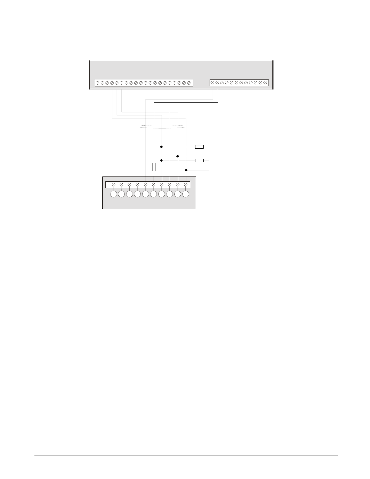
4.4.1.2 AS271
A resistor should be added between the COM and the Ext on the panel PCB. This resistor prevents the
panel being constantly in a trouble condition. Both the internal and external sirens are supervised.
This wiring configuration for the AS271 allows the beacon to follow the internal sounder.
1
Tamper
4
0 V speaker
2
Tamper
5
0 V beacon (AS271 only)
3
+13.8 V
CSX75
AS271
DATA
AUX+
COM
I
N
T
COM
EXT
R1NC
R1NO
R
1
C
AUX+
OUT2
COM
R
3
N
C
R3NO
R3C
AUX+
COM
O
U
T
4
TAMPER
T
A
M
P
E
R
Z1
COM
Z2
Z
3
COMZ4Z5
COM
Z
6
Z7
COM
Z8
4K7
4K7
12345
4K7
Page 32
CS875-575-375-275-175 Installers Manual with CS5500 keypadA.4.13
4.4.1.3 AS290/390
Cut jumpers 5 and 7 for negative hold-off on the sounder.
Information on programming the sounders can be found in chapter B-2 Programming the control panel.
4.5 Wiring fire detectors
In a 4-wire configuration, you can connect as many fire detectors, as long as you do not exceed the AUX power
capacity of the panel.
In a 2-wire configuration, you can connect a maximum of three fire detectors on the same loop.
1
Piezo
4
Beacon
7
GND
2
Piezo
5
Tamper
8
+13.8 V
3
Beacon
6
Tamper
9
Siren - hold off
A
Beacon - hold off
CSX75
AS290/390
DATA
AUX+
COM
I
N
T
COM
EXT
R1NC
R1NO
R
1
C
AUX+
OUT2
COM
R
3
N
C
R3NO
R3C
AUX+
COM
O
U
T
4
TAMPER
T
A
M
P
E
R
Z1
COM
Z2
Z
3
COMZ4Z5
COM
Z
6
Z7
COM
Z8
4K7
4K7
98765432 101
4K7
DATA
AUX+
COM
I
N
T
COM
E
X
T
R1NC
R1NO
R
1
C
A
U
X
+
OUT2
COM
R
3
N
C
R
3
N
O
R
3
C
AUX+
COM
O
U
T
4
TAMPER
T
A
M
P
E
R
Z
1
COM
Z2
Z
3
C
O
M
Z4
Z
5
COM
Z
6
Z7
COM
Z8
9 8 7 6 5 4 3 2 10 1
Page 33

CS875-575-375-275-175 Installers Manual with CS5500 keypad A.4.14
4.5.1 4-wire fire detector (CS275-375-575-875)
4.5.2 2-wire fire detector (CS275-375-575-875)
A fire alarm is activated as an alarm on zone 8 for the CS375-575-875 and as an alarm on zone 7 on the
CS275. The fire detector power is connected to Aux and Output.
If you are using a 2-wire fire detector you must change the menu option for 2-wire fire detector to On.
The CS175 does not support a 2-wire fire detector. A fire alarm activates the zone connected to the 4-wire fire
detector.
1
+ Line in
4
NC (normally closed)
2
+ Line out
5
COM
3
- Line
6
NO (normally open)
1
+ Line in
2
+ Line out
3
- Line
CS275
CS375
CS575
CS875
DB702 +DB721R
DB702 +DB721R
C
O
M
Z
4
A
U
X
+
C
O
M
O
U
T
4
11
2
2
3
3
4
4
5
5
6
6
CS275
CS375
CS575
CS875
DB701 +DB721R
DB701 +DB721R
C
O
M
Z
4
A
U
X
+
A
U
X
+
C
O
M
C
O
M
O
U
T
4
O
U
T
4
1
1
22
3
3
Page 34

CS875-575-375-275-175 Installers Manual with CS5500 keypadA.4.15
4.5.3 4-wire fire detector (CS175)
If you are using a CS175, you must program output 3 for the fire detector.
1. Select Installer Menu>Control Panel>Outputs>Prog Outputs>Output 3>Event>Alarms>Fire Reset.
2. Make sure that the option to follow the event is 0. To do this, select Installer Menu>Control
Panel>Outputs>Prog Outputs>Output 3>Time and set the time to 0.
1
+ Line in
4
NC (normally closed)
2
+ Line out
5
COM
3
- Line
6
NO (normally open)
CS175
DB702 +DB721R
DB702 +DB721R
C
O
M
Z
1
A
U
X
+
C
O
M
S
M
O
K
E
11
2
2
3
3
4
4
5
5
6
6
Page 35

CS875-575-375-275-175 Installers Manual with CS5500 keypad A.4.16
4.6 Wiring the outputs
Information on programming the outputs can be found in chapter B-2 Programming the control panel.
1
1A rated contacts. Relays are powered and switched from the panel. No external power is needed to switch the relays.
2
Digital outputs limited to 40 mA.
1
1
2
2
2
2
2
2
2
2
CS175
CS875
CS575
CS375
CS275
DATA
AUX+
COM
INT
COM
EXT
R1NC
R1NO
R1C
AUX+
OUT2
COM
R3NC
R3NO
R3C
AUX+
COM
OUT4
TAMPER
TAMPER
DATA
AUX+
COM
I
N
T
COM
EXT
O
U
T
1
AUX+
OUT2
OUT3
AUX+
COM
OUT4
TAMPER
TAMPER
DATA
AUX+
COM
E
X
T
COM
OUT1
OUT2
S
M
O
K
E
AUX+
COM
TAMPER
Z
1
COM
Z2
Z3
COM
Z4
Page 36

CS875-575-375-275-175 Installers Manual with CS5500 keypadA.4.17
4.7 Control unit wiring diagrams
4.7.1 CS175
4.7.1.1 Inputs and outputs
1
Zones 1-4
6
External sounder
B
Serial expansion
2
Box tamper input
7
Keypad bus
C
Phone line connector
3
Fire detector reset output
8
Additional keypad bus connection
D
Phone line communication LED
4
Open collector 2
9
Lid tamper
5
Open collector 1
A
Bus supervision LED
DATA Communication/Expander data (0101) (including keypad) COM Ground
AUX + Communication/Expander power (including keypad) TAMPER Tamper loop
COM Communication/Expander ground (including keypad) Z1 Zone 1
EXT External bell return COM Ground
COM Ground Z2 Zone 2
OUT 1 Output 1 Z3 Zone 3
OUT 2 Output 2 COM Ground
SMOKE Fire detector reset output Z4 Zone 4
AUX + Power
J14
RED
J15
BLACK
.
.
J16
J1
COMZ2Z3
Z1
Z4
DATA
AUX+
COM
EXT
O
U
T
2
A
U
X
+
C
O
M
T
A
M
P
E
R
S
M
O
K
E
O
U
T
1
5
7 6
4
3
2 1
S1
J17
EXPANSION
LED 2
LED 3
DATA
AUX+
COM
E
X
T
C
O
M
O
U
T
1
O
U
T
2
S
M
O
K
E
A
U
X
+
C
O
M
T
A
M
P
E
R
Z
1
C
O
M
Z
2
Z
3
C
O
M
Z
4
Page 37

CS875-575-375-275-175 Installers Manual with CS5500 keypad A.4.18
4.7.2 CS275
4.7.2.1 Inputs and outputs
1
Zones 1-6
7
Open collector 1
C
Serial expansion
2
Lid tamper
8
External sounder
D
Bus supervision LED
3
Box tamper input
9
Internal sounder
E
Full expansion port
4
Open collector 4 (2 wire smoke)
A
Keypad bus
F
Phone line connector
5
Open collector 3
B
Additional keypad bus connection
G
Phone line communication LED 3
6
Open collector 2
C
Serial expansion
DATA Communication/Expander data (0101) (including keypad) OUT 4 Output 4
AUX + Communication/Expander power (including keypad) TAMPER Tamper loop
COM Communication/Expander ground (including keypad) Z1 Zone 1
INT Internal bell return COM Ground
COM Ground Z2 Zone 2
EXT External bell return Z3 Zone 3
OUT1 Output 1 COM Ground
AUX + Power Z4 Zone 4
OUT 2 Output 2 Z5 Zone 5
OUT 3 Output 3 COM Ground
AUX + Power Z6 Zone 6
COM Ground
11
S1
J14
RED
J15
BLACK
J16
J1
. .
COMZ2Z3
COMZ1COMZ4Z5
Z6
J18
12
J17
EXPANSION
DATA
AUX+
INT
COM
EXT
O
U
T
2
A
U
X
+
A
U
X
+
C
O
M
T
A
M
P
E
R
O
U
T
4
T
A
M
P
E
R
O
U
T
3
O
U
T
1
13 14
15
16
4
1
9 8
7
6 5
3
2
LED 2
LED 3
DATA
AUX+
COM
I
N
T
C
O
M
E
X
T
O
U
T
1
AUX+
OUT2
O
U
T
3
AUX+
C
O
M
O
U
T
4
T
A
M
P
E
R
T
A
M
P
E
R
Z1
COM
Z2
Z3C
O
M
Z
4
Z5
C
O
M
Z
6
Page 38

CS875-575-375-275-175 Installers Manual with CS5500 keypadA.4.19
4.7.3 CS375, CS575 and CS875
*Always use in parallel. Only one or the other can be used.
1
Zones 1-8
7
Relay 1
D
Bus supervision LED
2
Lid tamper *
8
External sounder
E
Full expansion port
3
Box tamper input *
9
Internal sounder
F
Phone line connector
4
Open collector 4 (2 wire smoke)
A
Keypad bus
G
Phone line communication LED
5
Relay 3
B
Additional keypad bus connection
6
Open collector 2
C
Serial expansion
S1
J14
RED
J15
BLACK
J16
. .
11
J18
12
J17
EXPANSION
13 14
15
16
T
A
M
P
E
R
T
A
M
P
E
R
J1
COMZ2Z3
COM
Z1
COMZ4Z5Z6Z7Z8COM
DATA
AUX+
R1C
INT
COM
EXT
R1NO
R1NC
O
U
T
2
R
3
N
C
R
3
N
O
A
U
X
+
A
U
X
+
R
3
C
C
O
M
O
U
T
4
1
9 8
7 6
5
4
3
2
LED 2
LED 3
Page 39

CS875-575-375-275-175 Installers Manual with CS5500 keypad A.4.20
4.7.3.1 Inputs and outputs
DATA Communication/Expander data (0101) (including keypad)
AUX + Communication/Expander power (including keypad)
COM Communication/Expander ground (including keypad)
INT Internal bell power
COM Ground
EXT External bell return
R1NC Relay 1 (normally closed)
R1NO Relay 1 (normally open)
R1C Relay 1 (ground)
AUX + Power
OUT 2 Output 2
COM Ground
R3NC Relay 3 (normally closed)
R3NO Relay 3 (normally open)
R3C Relay 3 (ground)
AUX + Power
COM Ground
OUT 4 Output 4
TAMPER Tamper loop
Z1 Zone 1
COM Ground
Z2 Zone 2
Z3 Zone 3
COM Ground
Z4 Zone 4
Z5 Zone 5
COM Ground
Z6 Zone 6
Z7 Zone 7
COM Ground
Z8 Zone 8
DATA
AU
X+
COM
I
N
T
C
O
M
E
X
T
R
1
N
C
R
1
N
O
R
1
C
A
U
X
+
O
U
T
2
C
O
M
R
3
N
C
R
3
N
O
R
3
C
A
U
X
+
C
O
M
O
U
T
4
T
A
M
P
E
R
T
A
M
P
E
R
Z
1
C
O
M
Z
2
Z
3
C
O
M
Z
4
Z
5
C
O
M
Z
6
Z
7
C
O
M
Z
8
Page 40

CS875-575-375-275-175 Installers Manual with CS5500 keypadA.5.1
Chapter 5: Programming the system
5.1 Powering up the system
When the CS5500 if powered up for the first time, the language, keypad defaults, partition and keypad must be
set. These options must also be set each time a keypad is defaulted.
• The language option sets the first language of the keypad.
• The keypad defaults option sets the country specific keypad defaults. It does not default the keypad.
• The partition and keypad options set the keypad address.
Use the navigation keys to scroll between the different options and press OK to select an option. See Navigating
the menus for more information.
5.2 Entering programming mode
Your inst aller code allow s you to program the system through the installer menu. There are two levels in the
installer menu. The light menu contains the most important options and the advanced menu contains additional
options. The system cannot be armed while in programming mode on the current keypad or another keypad.
1. Press OK at the system prompt and enter your installer code. For a list of default codes, see chapter A-1
Introducing the CSx75 system.
2. Use the µ¶ keys to navigate the menu. The full menu map can be found in the Menu Structure included in
your language kit. The light menu is in green text and the advanced menu is in black text.
3. Select OK to select an option or use the numerical/character keys to edit the existing option.
<
'To switch to 'Advanced menu', navigate to Commands>Advanced and select Enabled. The keypad displays
the advanced menu until this option is disabled.
5.2.1 Changing the user interface language
1. Press OK at the system prompt.
2. Press OK again to display the system prompt in a different language.
3. Press OK until you find the language you require.
4. Continue using the keypad as normal.
For more information on setting languages, see chapter B-3 Programming the current keypads.
5.3 Navigating the menus
•Press the µ¶ keys to scroll through menu lists and options.
•Press # µ to move to the same menu item for the previous option. For example, if you are in a submenu for
zone 2, press # µ to move to the same submenu for zone 1.
•Press # ¶ to move to the same menu item for the next option. For example, if you are in a submenu for zone
2, press # ¶ to move to the same submenu for zone 3.
<
The keypad may timeout from the menu system and return to the default display.
5.3.1 Command menu
You can access a limited number of menu options without entering your installer code. This opens the command
menu.
1. Press OK at the system prompt.
2. Press the µ¶ keys to enter and navigate the command menu.
Page 41

CS875-575-375-275-175 Installers Manual with CS5500 keypad A.5.2
5.4 Selecting a menu option
• Press OK to select a menu option and move forward in the menu structure.
• Press NO to reject a menu option and move backwards in the menu structure.
• Press F1 to move through the second line of the LCD display, one word at a time, from right to left.
• Press F3 to move through the second lin e of the LCD display , one word at a time, from left to right.
5.5 Changing a menu option
The CSx75 has several editors that you can use to change the value of certain programmable menu options. You
can change selection list entries, binary entries, phone numbers and text. This section describes how to change
selection list entries, binary entries, numeric entries and phone numbers. For information on changing text, see
Editing text.
5.5.1 Changing selection list entries
1. Navigate with the µ¶ keys to the relevant menu option and press OK.
2. The current value for the menu option is displayed, for example, Enabled.
3. Press the µ¶ keys to change the value, for example, change Enabled to Disabled.
4. Press OK to accept the change.
- If the new value is valid, the keypad beeps once to confirm the change and returns to the menu option.
- If the new value is invalid, the keypad beeps three times to reject the change and returns to the menu
option.
5. Press NO to cancel the change and return to the menu option.
5.5.2 Changing binary entries
1. Navigate with the µ¶ keys to the relevant menu option and press OK.
2. The current value for the menu option is displayed, for example, 1 2 3 - - - - 8 means that 1, 2, 3 and 8 are on
(included) while 4, 5, 6 and 7 are off (excluded).
3. Press the corresponding numerical key to change a value, for example, press 1 to change the state of 1 to off
and press 4 to change the state of 4 to on. The display changes to - 2 3 4 - - - 8.
4. Press OK to accept the changes.
- If the new values are valid, the keypad beeps once to confirm the change and returns to the menu option.
- If the new value is invalid, the keypad beeps three times to reject the change and returns to the menu
option.
5. Press NO to cancel the changes and return to the menu option.
5.5.3 Changing numeric entries
1. Navigate with the µ¶ keys to the relevant menu option and press OK.
2. The current value for the menu option is displayed, for example, 55.
3. Do one of the following:
- Press a number key to clear the current value and display the value of the key pressed.
- Press µ to increase the current value by one.
Page 42

CS875-575-375-275-175 Installers Manual with CS5500 keypadA.5.3
-Press ¶ to decrease the current value by one.
-Press ## to clear the current value to 0.
4. Press the number keys to enter the value.
5. Press OK to accept the changes.
- If the new value is valid, the keypad beeps once to confirm the change and returns to the menu option.
- If the new value is invalid, th e keypad beeps three times to reject the change and returns to the menu
option.
6. Press NO to cancel the changes and return to the menu option.
5.5.4 Changing phone numbers and phone prefixes
1. Navigate with the µ¶ keys to the relevant menu option and press OK.
2. The current value for the menu option is displayed, for example, 4567999.
3. Do one of the following:
-Press µ to toggle between insert mode and overwrite mode (insert mode allows you to insert new
numbers and overwrite mode allows you to overwrite existing numbers).
-Press ¶ to delete the number at the cursor position.
-Press #¶ to delete all the numbers from the number at the cursor position to the end of the string.
4. Do one of the following:
-Press the keys 0 to 9 to insert new numbers.
-Press #0 to insert G.
-Press #1 to insert a star.
-Press #2 to insert #.
-Press #3 to insert a four-second delay when programming numbers on the control panel.
-Press #3 to insert + when programming numbers on the CS7002 GPRS module.
-Press #4 to insert P (this enables pulse dialing).
5. Press OK to accept the changes.
- If the new number is valid, the keypad beeps once to confirm the change and returns to the menu option.
- If the new number is invalid, the keypad beeps three times to reject the change and returns to the menu
option.
6. Press NO to cancel the changes and return to the menu option.
5.6 Exiting the menu system
1. Press ## to display the OK to Exit prompt.
2. Press OK at this prompt to exit the menu system.
5.7 Editing text
5.7.1 Overview
The CSx75 has a text editor that includes a word library. You can use this editor to change the text of certain
programmable text options.
Page 43

CS875-575-375-275-175 Installers Manual with CS5500 keypad A.5.4
1. Navigate with the µ¶ keys to the relevant menu option and press OK.
2. Press OK to select the language you want to edit.
3. The current text for the menu option is displayed, for example, Zone 2.
4. Do one of the following:
• Press µ to toggle between insert mode and overwrite mode (insert mode allows you to insert new text and
overwrite mode allows you to overwrite existing text).
• Press ¶ to delete the character at the cursor position.
• Press #¶ to delete all the characters from the character at the cursor position to the end of the string.
5. Press the keys 0 to 9 to insert new characters. Each key cycles through lower case and then upper case
characters.
6. Press OK to accept the changes. The keypad beeps once to confirm the change and returns to the menu
option.
7. Press NO to cancel the changes and return to the menu option.
<
A flashing cursor highlights the character you are editing. Press F2 to toggle flashing on the current word.
5.7.2 Example
To cha nge a zone name from Zone 2 to Upstairs:
1. Navigate to Zone 2 and press OK.
2. Press #F1 to go to the start of the zone name.
3. Press #¶ to delete all the characters.
4. Press 8 four times to enter the upper case letter ‘U’.
5. Press 7 once to enter the lower case letter ‘p’. Continue until you have entered the new zone name.
6. Press OK to save your changes.
<
Each character key cycles through lower and upper case letters and language specific characters.
5.7.3 Word library
The word library is a predefined collection of words that speeds up text editing. As you type a character, the
keypad automatically displays a matching word. The word library is enabled by default. For a complete list of
words in the word library, see chapter C-1 Appendix 6: Word library words.
• To accept the word, press F3. The cursor moves to the end of the new word and you can continue to enter
text.
• To accept a shortened version of the word, press F3 to accept the word. Then move the cursor to the
unnecessary characters and press ¶ to delete them.
• To reject the word, continue entering text as normal.
• Press the µ¶ keys to scroll through the list of word library words.
• To disable the word library:
1. Navigate with the µ¶ keys to Word Li brary and press OK.
2. The current state of the word library is displayed. In this case, it is enabled.
3. Use the µ¶ keys to change the state to disabled and press OK.
Page 44

CS875-575-375-275-175 Installers Manual with CS5500 keypadA.5.5
4. The keypad beeps once to accept the change and returns to Word Library.
5.7.4 Installer message
Up to four messages can be displayed on the LCD when the keypad is idle or when it times out from a menu. If
you enable more than one message, the messages are shown in a continuous cycle.
• Installer message
• Date and time
• Service required
• System ready/not ready
To enable the installer message:
1. Navigate with the µ¶ keys to This Keypad and press OK.
2. Select Keypad Features>Display and press OK.
3. Scroll to Custom Message and press OK. The current status of the installer message is displayed. In this case,
it is disabled.
4. Use the µ¶ keys to change the status to enabled and press OK.
5. The keypad beeps once to accept the change and returns to Custom Message.
Page 45

CS875-575-375-275-175 Installers Manual with CS5500 keypad A.6.1
Chapter 6: Setting up a communicator
6.1 Reporting
The CSx75 supports different modes of reporting events to multiple central stations. There are six phone
numbers - each phone number has it own account code, protocol and events. The configured prefix is common to
all six phone numbers. If a four-second delay is specified in the prefix, the panel does not look for a dial tone, but
performs blind-dialling. The following scenarios are examples of how to set different modes of reporting.
6.1.1 Reporting to one phone number
The control panel reports events to one central station only. You specify settings for phone number 1. Events for
phone number 1 are enabled by default.
<
The characters B, C, D, E, F can be used in control panel account codes. The letter ‘A’ cannot be used as
part of the code as it is a termination digit.
6.1.2 Backup reporting
Backup reporting configures the control panel to report to two or more central stations. The first ph one num ber
belongs to the main central station and all other phone numbers belong to the backup central stations. Events are
reported to the first number but, if the panel cannot reach this number, it dials the backup number(s). The control
panel makes two calls to each number in sequence. It performs the sequence for the number of times specified in
ARC Dial Attempts or until it receives a kiss off. The same account code is used to report to all numbers. Events
for phone number 1 are enabled by default and events for phone numbers 2 - 6 are disabled by default. If phone
number 1 and phone number 2 are programmed, the default sequence is 1,1 2,2 1,1,2,2 for a total of eight calls to
each number.
Level 1 Level 2 Value State
Phone Number Phone Number 1 123456
Phone Number 2
Account Code Phone Number 1 BE5566
Phone Number 2
Protocol Phone Number 1 SIA
Phone Number 2
Events Phone Number 1 – Alarms Enabled
Phone Number 1 – Alarm Restores Enabled
Phone Number 1 – Tampers and Restores Enabled
Phone Number 2 – Alarms
Phone Number 2 – Alarm Restores
Phone Number 2 – Tampers and Restores
Level 1 Level 2 Value State
Phone Number Phone Number 1 123456
Phone Number 2 456789
Account Code Phone Number 1 BE5566
Phone Number 2 445566
Protocol Phone Number 1 SIA
Phone Number 2 SIA
Page 46

CS875-575-375-275-175 Installers Manual with CS5500 keypadA.6.2
6.1.3 Dual reporting
Dual reporting configures the control panel to report to two different central stations. Events must be reported to
both phone numbers. The control panel dials the first number twice. If it cannot reach this number, it dials the
second number twice. It performs this sequence for the number of times specified in ARC Dial Attempts or until it
reports the events to both numbers. The same account code is used to report to both numbers. Events for phone
number 1 are enabled by default and events for phone number 2 are disabled by default.
6.1.4 Split reporting
Split reporting configures the control panel to report to two different central stations. Some events must be
reported to phone number 1 and others to phone number 2. The control panel dials the first number twice. If it
cannot reach this number, it dials the second number twice. It performs this sequence for the number of times
specified in ARC Dial Attempts or until it reports the relevant event to each number. The same account code is
used to report to both numbers. Events for phone number 1 are enabled by default and events for phone numbers
2 are disabled by default.
Events Phone Number 1 – Alarms Enabled
Phone Number 1 – Alarm Restores Enabled
Phone Number 1 – Tampers and Restores Enabled
Phone Number 2 – Alarms Disabled
Phone Number 2 – Alarm Restores Disabled
Phone Number 2 – Tampers and Restores Disabled
Level 1 Level 2 Value State
Phone Number Phone Number 1 123456
Phone Number 2 456789
Account Code Phone Number 1 BE5566
Phone Number 2 445566
Protocol Phone Number 1 SIA
Phone Number 2 SIA
Events Phone Number 1 – Alarms Enabled
Phone Number 1 – Alarm Restores Enabled
Phone Number 1 – Tampers and Restores Enabled
Phone Number 2 – Alarms Enabled
Phone Number 2 – Alarm Restores Enabled
Phone Number 2 – Tampers and Restores Enabled
Level 1 Level 2 Value State
Phone Number Phone Number 1 123456
Phone Number 2 456789
Account Code Phone Number 1 BE5566
Phone Number 2 445566
Protocol Phone Number 1 SIA
Phone Number 2 SIA
Level 1 Level 2 Value State
Page 47

CS875-575-375-275-175 Installers Manual with CS5500 keypad A.6.3
Events Phone Number 1 – Alarms Enabled
Phone Number 1 – Alarm Restores Enabled
Phone Number 1 – Tampers Disabled
Phone Number 2 – Alarms Disabled
Phone Number 2 – Alarm Restores Disabled
Phone Number 2 – Tampers and Restores Enabled
Level 1 Level 2 Value State
Page 48

Section B
Installing and programming the
modules
1 Enrolling modules ...........................................................................................................................................................B-1-1
2 Programming the control panel ..............................................................................................................................B-2-1
3 Programming the current keypads .......................................................................................................................B-3-1
4 Programming the other keypads............................................................................................................................B-4-1
5 Setting up the RF receivers ........................................................................................................................................B-5-1
6 Setting up the CS208H / CS208 / CS216 ..............................................................................................................B-6-1
7 Setting up the CS507.....................................................................................................................................................B-7-1
8 Setting up the CS586.....................................................................................................................................................B-8-1
9 Setting up the CS534.....................................................................................................................................................B-9-1
10 Setting up the CS320...............................................................................................................................................B-10-1
11 Setting up the CS535...............................................................................................................................................B-11-1
12 Setting up the CS1700 ............................................................................................................................................B-12-1
13 Setting up the CS7002 ............................................................................................................................................B-13-1
14 Reserved ......................................................................................................................................................................B-14-1
15 Setting up the CS7050 ............................................................................................................................................B-15-1
16 Setting up the CS7501 ............................................................................................................................................B-16-1
17 Reading the event log.............................................................................................................................................B-17-1
18 Programming with the UDx75 software ........................................................................................................B-18-1
Page 49

CS875-575-375-275-175 Installers Manual with CS5500 keypad B.1.1
Chapter 1: Enrolling modules
To enroll and default the system modules, you must enable the advanced menu. Select Commands>Advanced
Menu>Enabled and press OK.
1.1 Enrolling the system modules
When you select the enrol modules process, new modules are enrolled on both the control panel and the keypad.
The keypad must enrol modules in order to display the relevant menu options.
1. Press OK at the system prompt and enter your installer code.
2. Navigate with the µ¶ keys to Enrol Modules>Enrol and press OK.
3. The keypad starts enrolling the modules. The Enrolling message is displayed while enrolment is taking
place (approximately 12 seconds). When the modules have been enrolled, a beep sounds and the message
disappears.
4. When the modules have been enrolled, the keypad returns to Enrol.
5. Verify the enrolled modules. Navigate with the µ¶ keys to Commands and press OK.
6. Scroll to Event Log and press OK. When the control panel enrols a module, it adds an enrol event to the
event log. This event contains the module number. Scroll through the event log to verify that each module
has been enrolled.
<
The modules are enrolled each time you leave programming mode. In this case, the Enrolling message is
displayed but no beep sounds.
1.2 Defaulting the modules
Each module can be defaulted. It is recommended that you default each module before modifying its settings.
1. Navigate with the µ¶ keys to Default Settings in the relevant module menu and press OK. In this case,
select Control Panel>Default Settings to restore the default control panel settings.
2. A confirmation message is displayed. Press OK to accept the default settings.
3. The keypad sounder beeps once to confirm the reset.
1.3 Glossary
Location Term Definition
1 Enrol Modules A menu option that activates the process by which the control makes an internal list of all
keypads and modules connected to the system.
1.1 Enrol A menu entry that groups enrolled module information.
1.2 Number of Modules A menu option that displays the total number of installed modules.
Enrol
Number of Modules
1.1
1.2
Page 50

CS875-575-375-275-175 Installers Manual with CS5500 keypadB.2.1
Chapter 2: Programming the control panel
2.1 Overview
You must enroll and default the control panel before you begin to program the system. For more information on
enrolling and defaulting, see chapter B-1 Enrolling modules.
2.2 Programming inputs
An input is any zone that is set up on the system. A zone is an area guarded by a group of one or more detection
devices. It represents a single input in the system.
A zone may reside in any combination of partitions. A zone that resides in more than one partition becomes a
common zone and is reported to its lowest partition number. A common zone is armed only when all the partitions
that it belongs to are armed. It is immediately disarmed when one of the partitions it belongs to is disarmed.
The control panel can have a maximum of eight on-board inputs. RF receivers and CS208H / CS208 / CS216
input expanders can be used to increase the number of inputs to a maximum total of 168 depending on the model
of the control panel. For more information on the maximum number of zones per model, see chapter A-2
Designing the CSx75 system. For information on RF receivers, see chapter B-5 Setting up the RF receivers. For
information on CS208H / CS208 / CS216 input expanders, see chapter B-2 Programming the control panel. To
program on-board inputs, select Installer Menu>Control Panel>Inputs.
*Enabled according to
Keyswitch zone option
Zone Type Name
End of Line Resistor
Loop Response
Double Knock
Swinger Shutdown
Bypassable
Force Arm able
Group Bypass
Zone Inact i v ity Moni to r
Pulsed Keyswitch*
No Keypad Display**
Attributes
Fire
24-hour
Keyswitch
Follower/Access*
Delay 1
Delay 2
Interior
Entry Guard
Final Set Doo r
Roller Shutter
B-Alarm Trip
Trou ble
Local Only
Restore Reporting*
Dialler Delay
Listen-in
Copy Zone Type
(1) Zone 1
Zone Type
Zone Name
<Language 1>
Partitions
Copy Zone
Input Type
(1) Burglary
2.1.1.1.1
2.1.1.1.2
2.1.1.1.3
2.1.1.1.2.1
2.1.3.1.1
2.1.3.1.1.1
2.1.3.1.2
2.1.3.1.3
2.1.3.1.1.2
2.1.3.1.1.3
2.1.3.1.1.4
2.1.3.1.1.5
2.1.3.1.1.6
2.1.3.1.1.7
2.1.3.1.1.8
2.1.3.1.1.9
2.1.3.1.1.10
2.1.3.1.1.11
2.1.3.1.1.12
2.1.3.1.3.10
2.1.3.1.6
2.1.3.1.3.9
2.1.3.1.3.8
2.1.3.1.3.7
2.1.3.1.3.6
2.1.3.1.3.5
2.1.3.1.3.4
2.1.3.1.3.3
2.1.3.1.3.2
2.1.3.1.3.1
2.1.1.1.4
Zones
Swinger Shutdown
Zone Types
2.1.1 2.1.1.1
2.1.2
2.1.3
2.1.3.1
Zones 2 - 168
Same as above
If more th an 16 zones,
z
ones are first displayed
in groups and then as
above.
Languages 2 - 4
Same as above
Zone Types 2 - 20
Same as above
* Enabled accordin
g
to Key s witch
zone option
** Enabl e d accordin g to 24-hour
zone option
*Enabled a ccording to
24-hour zone option
Sound Yelping Siren - Bu rglary
Temporal Siren - Fire
Keypad Beeping
Chime
Reporting
2.1.3.1.5
2.1.3.1.4 2.1.3.1.4.1
2.1.3.1.4.4
2.1.3.1.4.3
2.1.3.1.4.2
2.1.3.1.5.1
2.1.3.1.5.4
2.1.3.1.5.3
2.1.3.1.5.2
(1) Burglary
2.1.3.1.6.1
* Enabled accordin
g
to Key s witch
zone option
Page 51

CS875-575-375-275-175 Installers Manual with CS5500 keypad B.2.2
2.2.1 Defining a zone
You must sel ect the language in which to program the new name and also assign partitions to the zone. You can
select the zone type and zone name for each new zone. The following steps explain how to select the zone type
and zone name for a new zone.
1. Navigate with the µ¶ keys to Control Panel>Inputs>Zones and press OK.
2. Select the zone number of the new zone to be configured and press OK.
3. Select Zone Type and press OK.
4. Scroll to the relevant zone type and press OK.
5. Select Zone Name and press OK.
6. Scroll to the relevant language and press OK. The current name for zone is displayed, for example, Zone 1.
7. Press µ to enter overwrite mode and press the keys 0 to 9 to insert new characters.
8. Press OK to accept the changes.
9. The keypad beeps once to confirm the change and returns to Zone Name.
10. Scroll to Partitions and press OK. The current partitions for that zone are displayed, for example, 1 2 3 - - -
- 8 means that 1, 2, 3 and 8 are included in the zone definition while 4, 5, 6 and 7 are excluded.
11. Press the corresponding numerical key to include or exclude a partition, for example, press 1 to exclude
partition 1 and press 4 to include partition 4. The display changes to - 2 3 4 - - - 8.
12. Press OK to accept the changes.
13. The keypad beeps once to confirm the change and returns to Partitions.
2.2.2 Copying zone settings
You can copy the settings for the current zone to another zone or a set of other zones. All the zone settings
(except the user defined zone name and RF settings) are copied to the target zones. The following steps explain
how to copy the settings from one zone to another.
1. Navigate with the µ¶ keys to Control Panel>Inputs>Zones and press OK.
2. Select the relevant zone number and press OK.
3. Scroll to Copy Zone and press OK.
4. The keypad prompts you to enter the start zone.
5. Enter the number of the first zone to which the settings will be copied and press OK.
6. The keypad prompts you to enter the end zone.
7. Enter the number of the last zone to which the settings will be copied and press OK.
8. The keypad prompts you to confirm your selection.
9. Press OK.
10. Copying message is displayed while the zone settings are copied. When copying is complete, the keypad
beeps once and returns to Copy Zone.
Page 52

CS875-575-375-275-175 Installers Manual with CS5500 keypadB.2.3
2.2.3 Editing a zone type
A zone type is a collection of characteristics. All the zones included in a particular zone type share the same
characteristics. Each zone must belong to a zone type. There are 20 pre-defined zone types which you can edit. To
edit a zone type, you must enable the advanced menu. The following example edits a burglary zone type so that
the input type is 24-hour and it can be automatically bypassed after five alarms within one arm period.
1. Ensure the advanced menu is enabled. See chapter 20 for more information.
2. Navigate with the µ¶ keys to Control Panel>Inputs>Zone Types and press OK.
3. Select Burglary>Input Type>24-hour>Yes and press OK.
4. The keypad beeps once to confirm the change and returns to 24-hour.
5. Scroll to Attributes>Swinger Shutdown>Yes and press OK.
6. The keypad beeps once to confirm the change and returns to Swinger Shutdown.
7. Set the value of Inputs>Swinger Shutdown to 5. For more information see Setting swinger shutdown below.
2.2.4 Setting swinger shutdown
Swinger shutdown allows the selected zone to be automatically bypassed after a specified number of alarms. To
configure swinger shutdown, you must enable the advanced menu. The following example sets swinger shutdown
to 5. This means that any zone for which swinger shutdown is enabled can be activated five times within one arm
period before it is automatically bypassed.
1. Ensure the advanced menu is enabled. See chapter 20 for more information.
2. Navigate with the µ¶ keys to Control Panel>Inputs>Swinger Shutdown and press OK.
3. Enter 5 and press OK.
4. The keypad beeps once to confirm the change and returns to Swinger Shutdown.
Page 53

CS875-575-375-275-175 Installers Manual with CS5500 keypad B.2.4
2.3 Programming outputs
The control panel includes up to four on-board auxiliary outputs. CS507 output expander modules and CS320
power modules can be used to increase the number of outputs. For more information on the CS507 output
expander, see chapter 11. For information on the CS320 power module, see chapter 15.
T o program on-board outputs, select Installer Menu>Control Panel>Outputs.
2.3.1 Configuring an output
You can change the characteristics of each output. You must specify the events and/or partitions that activate an
output and the length of time for which the output is activated. The events are grouped in the programming tree.
A full list of all possible selectable events can be found in Table 2-1: Control panel output events. The following
example configures output 1 to activate for 15 minutes when a burglary alarm occurs.
1. Navigate with the µ¶ keys to Control Panel>Outputs>Prog Outputs>Output 1 and press OK.
2. Scroll to Event>Alarms>Burglary Alarm and press OK.
3. The keypad beeps once to confirm the change and returns to Alarms.
4. Scroll to Time Unit>Minutes and press OK.
5. The keypad beeps once to confirm the change and returns to Time Unit.
6. Scroll to Time and press OK.
7. Select 15 min. and press OK to accept the changes.
8. The keypad beeps once to confirm the change and returns to Time.
1 (<Event>) Event Alarms
Arm/Disarm
Communications
Keypads
Sirens
Tam per/ Trouble
Tes ts
Miscellaneous
2.2.1.1.1
2.2.1.1.1.1
2.2.1.1.1.8
2.2.1.1.1.7
2.2.1.1.1.6
2.2.1.1.1.5
2.2.1.1.1.4
2.2.1.1.1.3
2.2.1.1.1.2
Prog Outputs
2.2.1 2.2.1.1
Outputs 2 - 4
Same as above
Sounds On
Short Blast On
Output Signa l Type
Sound On
Time Unit
Time
Partitions
Attributes
Phone Line Cut
Tam pers
Expander Trouble
Arming
Exit Expiry
Closing Kissoff
Keyswitch Arming
Phone Line Cut
Mains Failure
Low Battery
B-Alarm Trip
Tam pers
Expander Trouble
Latched
Code Stops Timer
Only if Closed
Only if Open
Inverted
When Armed
When Disarmed
When Armed
When Disarmed
2.2.1.1.2
2.2.1.1.5
2.2.1.1.4
2.2.1.1.3
2.2.2.1.1
2.2.2.2.1
2.2.2.2.4
2.2.2.2.3
2.2.2.2.2
2.2.3.1.1
2.2.3.1.6
2.2.3.1.5
2.2.3.1.4
2.2.3.1.3
2.2.3.1.2
2.2.3.1.1.1
2.2.1.1.5.1
2.2.1.1.5.5
2.2.1.1.5.4
2.2.1.1.5.3
2.2.1.1.5.2
2.2.2.1.1.1
2.2.2.1.3
2.2.2.1.2
2.2.2.1.1.2
2.2.3.1.1.2
Internal S i re n
Keypads
2.2.2
2.2.3
2.2.2.1
2.2.2.2
2.2.2.3
2.2.3.1
Page 54

CS875-575-375-275-175 Installers Manual with CS5500 keypadB.2.5
<
1. When Event 48 is programmed, it is possible to program a user code's authorization to select which
output(s) a particular code activates.
<
2. Always program Event 39, Fire al arm reset, to follow the event.
2.3.2 Configuring the internal siren
You can specify conditions and/or events that activate the internal siren. To configure the internal siren, you must
enable the advanced menu. The following example configures a short blast of the internal siren when the system
is armed using a keyswitch.
1. Ensure the advanced menu is enabled.
2. Navigate with the µ¶ keys to Control Panel>Outputs>Internal Siren>Short Blast On and press OK.
Table 2-1: Control panel output events
# Event # Event # Event
Misc Keypads Alarms
8 Any Bypass 12 Keypad Fire 0 Burglary Alarm
11 Duress 13 Keypad Medical 1 Fire Alarm
48 Code Entry (Note 1) 14 Keypad Panic 2 24-hour Alarm
37 Program Mode 15 Keypad Tamper 3 Trouble Alarm
49 * Keyfob Funct 1 27 Chime 4 Tamper Alarm
50 * Keyfob Funct 2 47 Keypad Beeping 46 Any Alarm
Tests 56 Audible Panic 17 Alarm Memory
29 Dyn Battery Test 57 Silent Panic
Sirens
52 Manual Test
Tampers and faults 5 Burglary Siren
16 Automatic Test 25 Fire LED 6 Fire Siren
59 Walktest Mode 39 Smoke Det Reset (Note 2) 7 Any Siren
Arm/Disarm 40 Over-current 60 External Siren
21 Armed 41 Box Tamper 61 Internal Siren
22 Disarmed 42 Siren Tamper
Communications
23 Ready to Arm 43 Any Open Circuit 32 Listen-in
24 Not Ready to Arm 44 Any Short Circ’t 33 Line Seizure
53 Armed Away 45 Any Open/Short 35 Fail to Comm’ate
54 Armed Stay 26 Fire Trouble 36 Phone Line Fault
30 Open Period 28 Expander Trouble 38 Downloading
31 Closed Period 9 Mains Failure 55 Aux Comm Fail
18 Entry 10 Low Battery
19 Exit
20 Entry or Exit
*
Events 49 and 50 require RX8w8, RX16w8, RX32w8, RX8i4, RX16i4, or RX48i4 wireless receivers to operate.
If set to latched condition, these events are one second
.
Page 55

CS875-575-375-275-175 Installers Manual with CS5500 keypad B.2.6
3. Scroll to Keyswitch Arming>Yes and press OK.
4. The keypad beeps once to confirm the change and returns to Keyswitch Arming.
2.3.3 Programming the keypad sounder
You can specify conditio ns and/o r event s that activate the keypad sounder. To configure the sounder, you must
enable the advanced menu. The following example programs the keypad sounder to activate when an expander
trouble condition occurs.
1. Ensure the advanced menu is enabled.
2. Navigate with the µ¶ keys to Control Panel>Outputs>Keypads>Sound On and press OK.
3. Scroll to Expander Tr ouble>Enabled and press OK.
4. The keypad beeps once to confirm the change and returns to Expander Trouble.
2.4 Assigning codes
System codes can be either four or six digits long. There are two types of programmable code; an installer code
and a duress code. A duress code disarms the system and activates a duress alarm. This is a silent alarm that
sends a special report to the central station. T o program codes, select Installer Menu>Control Panel>Codes.
2.4.1 Setting up the installer code
An installer code has associated arming options and access rights. To set the authority and access rights, you
must enable the advanced menu. The following example assign partitions 1 and 2 to a new installer code that can
be used only to arm the system.
1. Ensure the advanced menu is enabled.
2. Navigate with the µ¶ keys to Control Panel>Codes>Installer Code and press OK twice.
3. Enter the new code and press OK.
4. Enter the new code and press OK.
5. The keypad beeps once to confirm the change and returns to Code.
6. Scroll to Authority>Arm Only>Yes and press OK.
7. The keypad beeps once to confirm the change and returns to Arm Only.
8. Navigate with the µ¶ keys to Partitions and press OK.
9. Press the corresponding numerical key to include partitions 1 and 4 and to exclude all other partitions and
press OK.
10. The keypad beeps once to confirm the change and returns to Partitions.
Duress Code
Code
Arm Only After Closing
Arm Only
Arm/Disarm
Master Code
Bypass Zones
Reports Op e n/Close
Installer Code
4/6 Digit Codes
Authority
2.3.1
2.3.2 2.3.2.1
2.3.2.2
2.3.2.2.1
2.3.2.2.2
2.3.2.2.3
2.3.2.2.4
2.3.2.2.5
2.3.2.2.6
Partitions
2.3.2.3
2.3.3
Page 56

CS875-575-375-275-175 Installers Manual with CS5500 keypadB.2.7
2.5 Setting communication options
C
hannels 1 - 8
Channels 9 - 16
Fast Format Channels
Communications
Program/Download
Zone Inactiv i t y Mo nitor
Power
Power Tr ouble and Restores
Aux
Overcurrent and Restores
Fail to Communicate
Tes t R ep o r t s
Miscellaneous
2.4.1.2.1.4.4
2.4.1.2 .1.4.5
2.4.1.2.1.5.1
2.4.1.2 .1.5.2
2.4.1.2.1.4.3.2
2.4.1.2.1.4.4.1
2.4.1.2.1.4.4.2
2.4.1.2. 1.4.5
.1
2.4.1.2.1.4.5.2
At Disarm
For Zones On Siren Timeout
Send Restores
2.4.1.2.1.5
Phone Numb
er
Account Code
Protocol
Phone Number 1
Phone Prefix
Central Station
Events
Alarms
Alarm Restores
Opening/Closings
Zone Byp a
ss and Resto res
Arm/Disarm/Alarm
Phone Numbers
Tam pe r/ Tro u ble Tamp e
rs and Restores
Zone Trouble a n d Restor e s
Expander Trouble and Res
tores
Siren/Phone Faults and Restores
RF Sensor Lost and Restores
RF Low
Battery and Restores
2.4.1
2.4.1.1
2.4.1.2.1 2.4.1.2.1.1
2.4.1.2
2.4.1.2.1.3
2.4.1.2.1.2
2.4.1.2.1.4
2.4.1.2.1.4.1
2.4.1.2.1.4.2
2.4.1.2.1.4.3
2.4.1.2.1.4.1 .1
2.4.1.2.1.4.1.2
2.4.1.2.1.4.1.3
2.4.1.2.1.4.1.4
2.4.1.2.1.4.2.1
2.4.1.2.1.4.2
.2
2.4.1.2.1.4.2.3
2.4.1.2.1.4.2.4
2.4.1.2.1.4.2.5
2.4.1.2.1.4.2.6
2.4.1.2. 1.4.3 .1
Phone Numbers 2 - 6
Same as above
(1)
Partition 1
Dial Attempts
Partition Account Codes
Diall
er Output Level
Dialler Abo rt Delay
Listen-in Time
ARC Dial Attempts
FTC Dial Attempts
Voice /Sir e n Di al Att
empts
2.4.1.3
2.4.1.4
2.4.1.5
2.4.1.7
2.4.1.6
2.4.1.8
2.4.1.3.1
2.4.1.4.1
2.4.1.4.2
2.4.1.4.3
2.4.1.8.1
2.4.1.8.2
Partitions 2 - 8
Same as above
Call Back Numbe
r
Access C ode
Call Back Reqd
Rings to Answer
Answer Machine Defeat
Call PC on Autotes
t
Require Code for Download
Up/Download
Syste
m Shutdown
Local Programming
Comms Settings
Download Settings
Autotest
Autotest Control
Interval
Hour
Minute
Time Since Test
L
o
c
k
o
u
t
2.4.2
2.4.3
2.4.2.1
2.4.2.8
2.4.2.7
2.4.2.6
2.4.2.5
2.4.2.4
2.4.2.3
2.4.2.2
2.4.3.1
2.4.3.5
2.4.3.4
2.4.3.3
2.4.3.2
2.4.2.8.1
2.4.2.8.2
2.3.2.8.3
2.4.2.8.4
Box Tamper
Expander Tr
ouble
Siren Supervision
RF Sensor Lost
RF Low Battery
Mains Failure
Low Batter y
Aux Overcurrent
Log Full
Start/End Programming
End Downloa d
Phone Line Cut
Fail t o Comm unic ate
Autotest
Autotest D
isarmed No Call
(1) Burglary SIA Code*
Contact ID Code*
FF Channel*
FF Restore Channel
4+2 Restore Code*
200Bd FSK Channel*
200Bd FSK Restore Channel
Voice Channel*
*
TELIM Channel*
TELIM Code*
4+2 Code*
*
2.4.4.3.1.1.1
2.4.4.3.1.1.2
2.4.4.3.1.1.3
2.4.4.3.1.1.4
2.4.4.3.1.1.5
2.4.4.3.1.1.6
2.4.4.3.1.1.7
Partition ReportsReporting Ope
ning/Closings
Zone By pass
Zone Re store
Zone Trou ble
Zone Tamp er
Cance
l
Recent Closing
Exit Error
Tam pe r/ Tro u bl eSystem Report s
Communications
Miscellaneous
Power
Zone Types
Report Codes
Bypass on Force Arm
First
to Open/Last to Close
2.4.4
2.4.4.1
2.4.4.2
2.4.4.3
2.4.4.1.1
2.4.4.1.2
2.4.4.1.3
2.4.4.1.4
2.4.4.1.5
2.4.4.1.6
2.4.4.1.7
2.4.4.1.8
2.4.4.2.1
2.4.4.2.2
2.4.4.2.3
2.4.4.2.4
2.4.4.2.5
2.4.4.2.6
2.4.4.3.1
2.4.4.2.1.1
2.4.4.2
.1.2
2.4.4.2.1.3
2.4.4.2.1.4
2.4.4.2.1.5
2.4.4.2.2.1
2.4.4.2.2.2
2.4.4.2.2.3
2.4.4.2. 3.1
2.4.4.2.3.2
2.4.4.2.3.3
2
.4.4.2.3.4
2.4.4.2.4.1
2.4.4.2.4.2
2.4.4.2.4.3
2.4.4.3.1.1
Z
o
n
e
T
y
p
e
s
2
-
2
0
S
a
m
e
a
s
a
b
o
v
e
2.4.4.3.1.1.8
2.4.4.3.1.1.9
2.4.4.3.1.1.10
Opening
Closing
Partarm
Recent Closing
Exit Error
Cancel
FF Channel*
T
EL
IM Channel*
4+2 Code*
200Bd FSK Channel*
Voice Channel*
Zone
T
amper
Zone
T
rouble
Siren
T
amper
Box
T
rouble
Expander
T
rouble
RF Sensor Lost
RF Low Battery
FF Channel*
FF Restore Channel
4+2
Restore Code*
200Bd FSK Channel*
200Bd FSK Restore Channel
Voice Channel*
*
T
ELIM Channel*
4+2 Code*
*
FF Channel *
T
ELIM Channel*
4+2 Code*
2
00Bd FSK Channel*
Voice Channel*
B-Alarm
T
rip
2.4.4.3.2.1.1
2.4.4.3.2.1.2
2.4.4.3.2.1.3
2.4.4.3.2.1.4
2.4.4.3.2.1.5
2.4.4.3.3.1.1
2.4.4.3.3.1.2
2.4.4.3.3.1.3
2.4.4.3.3.1.4
2.4.4.3.3.1.5
2.4.4.3.3.2.1
2.4.4.3.3.2.2
2.4.4.3.3.2.3
2.4.4.3.3.2.4
2.4.4.3.3.2.5
2.4.4.3.3.2.6
Open/Close/Cancel
Tam per /Tr ou bl e
2.4.4.3.2
2.4.4.3.3
2.4.4.3. 2.1
2.4.4.3.2.2
2.4.4.3.2.3
2.4.4.3.2.4
2.4.4
.3.2.5
2.4.4.3.2.6
2.4.4.3. 3.1
2.4.
4.3.3.2
2.4.4.
3.3.3
2.4.4.3.3.4
2.4.4.3.3.5
2.4.4.3. 3.6
2.4.4.3.3.7
2.4.4.3. 3.8
2.4.4.3.3.2.7
Format Ove rride
2.4.5
Features 1
Features 2
2.4.5.1
2.4.5.2
Mains Failu re
Low Battery
Aux Overcurrent
Duress
Keypad Tamper
Keypad P anic
Keyp
ad Aux 1 (Fire)
Keypad Aux 2 (Medical)
FF Channel*
FF Restore Ch
annel
4+2 Code*
4+2 Restore Code*
200Bd FSK Channel*
*
TELIM Channel*
200Bd FSK Res
tore Channel*
Voice Channel*
FF Channel*
TELIM Channel*
4+2 Code
*
200Bd FSK Channel*
Voice Channel*
2.4.4.3.4.1.1
2.4.4.3.4.1.2
2.4.4.3.4.1.3
2.4.4.3.4.1.4
2.4.4.3.4.1.5
2.4.4.3.5.1.1
2.4.4.3.5.1.2
2.4.4.3.5.1.3
2.4.4.3.5.1.4
2.4.4.3.5.1.5
2.4.4.3.5.1.6
Keypad
P
ower
2.4.4.3.4
2.4.4.3.5
2.4.4.3.4.1
2.4.4.3.4.2
2.4.4.3.4.3
2.4.4.3.4.4
2.4.4.3.4.5
2.4
.4.3.5.1
2.4.4.3.5.2
2.4.4.3. 5.3
2.4.4.3.5.1.7
FF Channel*
FF Restore C
hannel
T
ELIM Channel*
4+2 Code*
4+2 Restore Code*
200Bd FSK Channel*
Voice Channel*
*
200Bd FSK Re
store Chan n el*
Phone
Line Cut
2.4.4.3.6.1.1
2.4.4.3.6.1.2
2.4.4.3.6.1.3
2.4.4.3.6.1.4
2.4.4.3.6.1.5
2.4.4.3.6.1.6
Communications
2.4.4.3. 6
2.4.4.3 .6.1
Log Full
Start Programming
End Programming
End Download
Fail to Commun i c a te
Autotes t
FF Channel*
T
ELIM
Channel*
4+2 Code*
200Bd FSK Channel*
Voice Channel*
(1) Zone 1
2.4.4.3.6.2.1
2.4.4.3.6.2.2
2.4.4.3.6.2.3
2.4.4.3.6.2.4
2.4.4.3.6.2.5
20
0Bd FSK Channel*
FF Channe l *
T
ELIM Ch
annel*
4+2 Code*
200Bd FSK Channel*
Voice C hannel *
2.4.4.3.7.1.1
2.4.4.3.7.1.2
2.4.4.3.7.1.3
2.4.4.3.7.1.4
2.4.4.3.7.1.5
2.4.4.3.8.1.1
Miscellane ous
Zones 200Bd FSK
2.4.4.3.7
2.4.4.3.8
2.4.4.3.6.2
2.4.4.3.6.3
2.4.4.3.7.1
2.4.4.3.7.2
2.4.4.3.7.3
2.4.4.
3.7.4
2.4.4.3.8.1
Zones 2 - 99 same as above.
If more than 16 zones, zones are first display ed
in
g
roups an d then dis
played as above.
*If relevant protocol set in Phone Num be rs
2.4.4.3.6.1.7
2.4.4.3.1.1.11
2.4.4.3.3.2.8
2.4.4.3
.5.1.8
2.4.4.3.6.1.8
Page 57

CS875-575-375-275-175 Installers Manual with CS5500 keypad B.2.8
The control panel can report to a central station after all or specified events. Communication between the control
panel and the central station is monitored to ensure against damage or faults. The control panel can also
communicate with up/download software when a download session has been established. To program control
panel communciation options, select Installer Menu>Control Panel>Communications.
2.5.1 Defining communication with a central station
You can specify up to six central stations to which the control panel reports events. You can also select the
events to be reported to each station. For more information on setting up a communicator, see chapter 21. For an
example of how to program phone settings, see chapter 5.
You can set a number of conditions that must be met before a communication session is established between the
control panel and the central station. To enable restore report options, you must enable the advanced menu. The
following example configures the control panel to ring the central station three times before a fail to
communicate condition occurs. It also enables a restore report to be sent at the moment the system is disarmed.
1. Ensure the advanced menu is enabled.
2. Navigate with the µ¶ keys to Control Panel>Communications>Central Station and press OK.
3. Scroll to Dial Attempts>FTC Dial Attempts and press OK.
4. Select 3 and press OK.
5. The keypad beeps once to confirm the change and returns to FTC Dial Attempts.
6. Navigate with the µ¶ keys to Send Restores>At Disarm>Yes At Disarm and press OK.
7. The keypad beeps once to confirm the change and returns to At Disarm.
2.5.2 Defining communication with upload/download software
You can set up a number of conditions that must be met before a communication session is established between
the control panel and the up/download software. For more information on programming using the upload/
download software, see chapter 22.
2.5.3 Configuring the system autotest
The autotest is run at configured intervals to ensure communication between the control panel and central station
or the control panel and up/download software is functioning correct ly. The following example sets the system
autotest to run every Friday at 12.45, assuming that today is Wednesday.
1. Navigate with the µ¶ keys to Control Panel>Communications>Autotest>Autotest Control>Days and
press OK.
2. Scroll to Interval>7 days and press OK.
3. The keypad beeps once to confirm the change and returns to Autotest Control.
4. Scroll to Hour>12 and press OK.
5. The keypad beeps once to confirm the change and returns to Hour.
6. Scroll to Minutes>45 and press OK.
7. The keypad beeps once to confirm the change and returns to Minutes.
8. Scroll to Time Since Test>5 Days and press OK.
9. The keypad beeps once to confirm the change and returns to Time Since Test.
Page 58

CS875-575-375-275-175 Installers Manual with CS5500 keypadB.2.9
2.5.4 Enabling reporting
You must enable event reporting in the control panel and program the events and zone types for which reports are
sent. You must specify the format of the report and, in the case of voice reports, you must map each event to a
recorded message. You can map one message to a number of events. The following example enables voice
reporting to phone number 2 for a phone line cut event and assigns a voice message to this event.
1. Navigate with the µ¶ keys to Control Panel>Communications>Central Station and press OK.
2. Scroll to Phone Numbers>Phone Number 2>Protocol>Voice and press OK.
3. The keypad beeps once to confirm the change and returns to Protocol.
4. Navigate with the µ¶ keys to Reporting>Report Codes>Communications and press OK.
5. Scroll to Phone Line Cut>Voice Channel and press OK.
6. Scroll to the number of the message that you want to map to that zone and press OK.
7. The keypad beeps once to confirm the change and returns to Voice Channel.
2.6 Configuring partitions
A partition is a group of zones which operate as a unit and can be armed and disarmed independently of other
partitions in the system. A partition is also known as an area. The control panel can be divided into separate
partitions with distinct zones, keypad and user codes for each partition. Arming and bypass options can be set for
each partition. To program partition settings, select Installer Menu>Control Panel>Partition Settings.
2.6.1 Setting timers
You can specify the time in which a user must disarm or arm a system before a full alarm occurs. The following
example sets time within which the user must leave the
protected zone after arming the system (12 seconds). It also
sets the time within which the user must disarm the system (10 seconds).
1. Navigate with the µ¶ keys to Control Panel>Partition Settings>Timers >Entry 1 and press OK.
2. Enter 12 and press OK.
3. The keypad beeps once to confirm the change and returns to Entry 1.
4. Scroll to Exit 1 and press OK.
5. Enter 10 and press OK.
Entry 1
Exit 1
Entry 2
Exit 2
Arming
Quick Arm
Re-exit
Silent Auto Arm
Silent Exit Always
Armin
g
with Zone Lost
Miscellaneous
Silent PA (7+9)
Audible PA (7+9)
Fire/Aux 1 (1+3)
Medical / Aux 2 (4+6)
Multi Code Tamper
LED Extinguish
Bypass Auto Bypass
Code Required
Sounder Alert
Bypass Toggle
Mains/Batt Sounder Alert
Zone Lost Gives Tamper
Timers
Feature Select
2.5.1
2.5.2
2.5.1.1
2.5.1.2
2.5.1.3
2.5.1.4
2.5.2.1
2.5.2.2
2.5.2.3
2.5.2.4
2.5.2.1.1
2.5.2.1.2
2.5.2.1.3
2.5.2.1.4
2.5.2.1.5
2.5.2.2.1
2.5.2.2.2
2.5.2.2.3
2.5.2.2.4
2.5.2.2.5
2.5.2.2.6
2.5.2.3.1
2.5.2.3.2
2.5.2.3.3
2.5.2.3.4
2.5.2.4.1
2.5.2.4.2
Keypads
Page 59

CS875-575-375-275-175 Installers Manual with CS5500 keypad B.2.10
6. The keypad beeps once to confirm the change and returns to Exit 1.
2.6.2 Configuring a partition
You can set partiti on feat ures including arming and bypassing options. You can also enable life safety keys for
the partition keypads. The following example allows the system to be armed with a lost zone and enables the
personal alarm combination keys so they activate a personal attack alarm when pressed.
1. Ensure the advanced menu is enabled.
2. Navigate with the µ¶ keys to Control Panel>Partition Settings>Feature Select>Arming and press OK.
3. Scroll to Arming with Zone Lost>Yes and press OK.
4. The keypad beeps once to confirm the change and returns to Arming with Zone Lost.
5. Navigate with the µ¶ keys to Keypads>Silent PA (7+9)> Yes and press OK.
6. The keypad beeps once to confirm the change and returns to Silent PA (7+9).
<
When the Arming with Zone Lost option is enabled, the user is always allowed to arm the system even if the
PIR or door/window sensor does not report within the short window. For more information on short windows,
see chapter 9.
2.7 Configuring the system
Configurable system settings include timers, input features, the system clock and serial port and various tests that
can be performed on the control panel. To program system settings, select Installer Menu>Control
Panel>System Settings.
Sounders
Batt Dynamic Test Duration
Mains Report Delay
Power Up Delay
Inputs
Power
Communications
Internal S i re n Ti me out
Extern a l S i re n Ti m eout
Chime Time
Phone Line Cut Delay
Inputs
On-board 8 zones
Box Tamper
2-wire Smoke Det e ctors
Force Default Zone Types
Batt Presence Test
Dynamic Batt Test at Armin
g
Manual Sire n Test
Manual Dialler Test
Walktest
Diagnostics
Fire Verification Time
Zone Inact. U nit
Zone Inactivity Monitor
Double Knock Time
Double Knock Open Time
B-Alarm Timer
Timers
Feature Select
Mains Frequency
Lost Clock Indication
Summer/Winter Tim e
Fire Siren
Master Code Resets Tamper Memory
Transfo r mer Siz e
All Abort
Blank Keypads
Reset Tamper Before Arming
Clock
Miscellaneous
2.6.1
2.6.2
2.6.1.1
2.6.1.2
2.6.1.3
2.6.1.4
2.6.2.1
2.6.2.2
2.6.2.3
2.6.2.4
2.6.1.1.1
2.6.1.1.2
2.6.1.1.3
2.6.1.1.4
2.6.1.1.5
2.6.1.1.6
2.6.1.2.1
2.6.1.2.2
2.6.1.2.3
2.6.1.3.1
2.6.1.3.2
2.6.1.3.3
2.6.1.4.1
2.6.2.1.1
2.6.2.1.2
2.6.2.1.3
2.6.2.1.4
2.6.2.2.1
2.6.2.2.2
2.6.2.2.3
2.6.2.2.4
2.6.2.2.5
2.6.2.3.1
2.6.2.3.2
2.6.2.3.3
2.6.2.4.1
2.6.2.4.2
2.6.2.4.3
2.6.2.4.4
2.6.2.4.5
2.6.3
Serial Port Connection Type
Speed
2.6.3.1
2.6.3.2
2.6.2.4.6
Page 60

CS875-575-375-275-175 Installers Manual with CS5500 keypadB.2.11
2.7.1 Setting timers
You can set timers to control the duration of various system functions. The following example sets the internal
siren timer to five minutes. When the siren starts ringing, the timer starts counting down. When the timer is
finished, the siren automatically cuts out.
1. Ensure the advanced menu is enabled. See chapter 20 for more information.
2. Navigate with the µ¶ keys to Control Panel>System Settings and press OK.
3. Scroll to Timers>Sounders>Internal Siren Timeout and press OK.
4. Enter 5 and press OK.
5. The keypad beeps once to confirm the change and returns to Internal Siren Timeout.
2.7.2 Configuring system features
You can specify various system features, enable the tests that can be performed on the control panel and set clock
options. The following example programs the control panel to activate the siren and make a manual test call to the
central station during the do self tests.
1. Ensure the advanced menu is enabled. See chapter 20 for more information.
2. Navigate with the µ¶ keys to Control Panel>System Settings>Feature Select and press OK.
3. Scroll to Diagnostics>Manual Siren Test>Enabled and press OK.
4. The keypad beeps once to confirm the change and returns to Manual Siren Test.
5. Scroll to Manual Dialler Test>Enabled and press OK.
6. The keypad beeps once to confirm the change and returns to Manual Dialler Test.
2.8 Setting arm schedules
The control panel can be programmed to automatically open and close partitions at specified times on specified
days. To program schedules, you must enable the advanced menu. Select Installer Menu>Commands>Advanced
Menu>Enabled and press OK. Then select Installer Menu>Control Panel>Arm Schedules.
2.8.1 Setting up schedules
You can set up a schedule to control the opening and autoarming events for each partition. The following example
sets a schedule for partition 1 so that it is automatically closed at 18.00 on a Monday if there is no activity in the
building. If there is activity at closing time, the control panel will try to arm after every 45 minutes of inactivity
until the next opening time, or until the system is armed manually.
Partitions Opening (1) Partition 1
Schedule Times
Partitions Autoarmin
g
Closing/Autoarm
Opening
(1) Partition 1
2.7.1
2.7.2
2.7.3
2.7.1.1
2.7.2.1
2.7.3.1
2.7.3.2
2.7.1.1.1
2.7.1.1.2
2.7.1.1.3
2.7.1.1.4
2.7.1.1.5
2.7.1.1.6
2.7.1.1.7
2.7.2.1.1
2.7.2.1.2
2.7.2.1.3
2.7.2.1.4
2.7.2.1.5
2.7.2.1.6
2.7.2.1.7
2.7.2.1.8
2.7.3.1.1
2.7.3.1.2
2.7.3.2.1
2.7.3.2.2
Hour
Minute
Sunday
Monday
Tue s day
Wednesday
Thursday
Friday
Saturday
Hour
Minute
Sunday
Monday
Tue s day
Wednesday
Thursday
Friday
Saturday
45 Minute Retry
Partitions 2 - 8
Same as above
Partitions 2 - 8
Same as above
Page 61

CS875-575-375-275-175 Installers Manual with CS5500 keypad B.2.12
1. Ensure the advanced menu is enabled. See chapter 20 for more information.
2. Navigate with the µ¶ keys to Control Panel>Arm Schedules and press OK.
3. Scroll to Partitions Autoarming>Partition 1>Sunday>Yes and press OK.
4. The keypad beeps once to accept the change and returns to Sunday.
5. Scroll to 45 Minute Retry>Enabled and press OK.
6. The keypad beeps once to accept the change and returns to 45 Minute Retry.
7. Navigate with the µ¶ keys to Schedule Times>Closing/Autoarm>Hour and press OK.
8. Enter 18 and press OK.
9. The keypad beeps once to confirm the change and returns to Hour.
10. Scroll to Minute and press OK.
11. Enter 0 and press OK.
12. The keypad beeps once to confirm the change and returns to Minute.
2.9 Programming the system to work with a home automation system
The control panel can communicate to home automation protocols such as the X-10 protocol. The connection
between the control panel and the X-10 home automation module is made through the CS507 output expander or
the CS534 listen-in module RJ11 connectors. The on-board RS232 connector on the CS275, CS375, CS575 and
Interface Configuration
Zone Name
Zone Status
Zone Snapshot
Partition Status
Partition Snapshot
System Status
Log Event
Interface Confi
g
uration
Zone Status
Zone Snapshot
Partition Status
Partition Snapshot
System Status
X-10 Message
Log Event
Keypad Message
Transition Broadcasts
Protocol
Commands/Requests
Misc Requests
Programming Progra m Da ta Request
Program Data Command
Misc Comma nds X-10 Message
Store Comms Event
Zone Bypass Toggle
User Info Request
Set User Code
Set User Authority
Keypad Fun c tio ns 1s t Keypad Fu n ctio n
2nd Keypad Function
Send Keypad Text
Keypad Terminal Mode
Set Date/Ti me
2.8.2.1
2.8.2.2
2.8.2.3
2.8.2.4
2.8.2.5
2.8.2.6
2.8.2.7
2.8.2.8
2.8.2.9
2.8.3.1
2.8.3.2
2.8.3.3
2.8.3.4
2.8.3.1.1
2.8.3.1.2
2.8.3.1.3
2.8.3.1.4
2.8.3.1.5
2.8.3.1.6
2.8.3.1.7
2.8.3.1.8
2.8.3.2.1
2.8.3.2.2
2.8.3.2.3
2.8.3.3.1
2.8.3.3.2
2.8.3.3.3
2.8.3.3.4
2.8.3.3.5
2.8.3.3.6
2.8.3.4.1
2.8.3.4.2
2.8.3.4.3
2.8.3.4.4
2.8.1
2.8.2
2.8.3
With PIN
Without PIN
With PIN
Without PIN
2.8.3.3.3.1
2.8.3.3.3.2
2.8.3.4.1.1
2.8.3.4.1.2
LCD Keypad Address
2.8.4
Page 62

CS875-575-375-275-175 Installers Manual with CS5500 keypadB.2.13
CS875 can be used to connect to other home automation systems. Consult your local Aritech Support to obtain
more information.
Updated system information can be sent from the control panel to the home automation system in binary or ASCII
format. The control panel can respond to requests sent by the home automation system and in turn can send
commands to the home automation system. To program home automation options, you must enable the advanced
menu. Select Installer Menu>Commands>Advanced Menu>Enabled and press OK. Then select Installer
Menu>Control Panel>Home Automation.
2.9.1 Enabling broadcasts
You can specify how updated information is sent to the home automation system from the RS232 interface. The
following example enables the home automation protocol to send different end-user messages to the keypad
display.
1. Ensure the advanced menu is enabled. See chapter 20 for more information.
2. Navigate with the µ¶ keys to Control Panel>Home Automation and press OK.
3. Scroll to Transition Broadcasts>Keypad Message>Enabled and press OK.
4. The keypad beeps once to accept the change and returns to Keypad Message.
2.9.2 Enabling commands and requests
You can specify which commands can be sent to the serial port by the home automation system. These include
arming and disarming, programming and bypassing zones. The following example enables primary keypad
functions that are sent by the home automation system with a valid user code.
1. Ensure the advanced menu is enabled. See chapter 20 for more information.
2. Navigate with the µ¶ keys to Control Panel>Home Automation and press OK.
3. Scroll to Commands/Requests>Keypad Functions>1st Keyad Function>With PIN>Enabled and press OK.
4. The keypad beeps once to confirm the change and returns to Wit h PIN .
Page 63

CS875-575-375-275-175 Installers Manual with CS5500 keypad B.2.14
2.10 Glossary
Location Term Definition
2 Control Panel This groups all options relating to the central processing unit of the alarm
system. The control panel monitors the detection devices and activates any
number of signalling devices.
2.1 Inputs A menu entry that groups options relating to all zones.
2.1.1 Zones An menu entry that groups zone options.
2.1.1.1.1 Zone Type An menu option that specifies the zone type of a particular zone.
2.1.1.1.2 Zone Name An menu option that allows the installer to define names for each installed
zone. For example, Zone 1 can be named Living Room PIR.
2.1.1.1.3 Partitions A menu entry that lists the partitions assigned to the selected zone. The
selected zone can trigger an event on these partitions.
A zone may reside in any combination of partitions. A zone that resides in
more than one partition becomes a common zone and is reported to its lowest
partition number. A common zone is armed only when all the partitions that it
belongs to are armed. It is disarmed the moment one of the partitions it
belongs to is disarmed.
2.1.1.1.4 Copy Zone A menu option that copies the settings for an individual zone to a contiguous
set of other zones.
2.1.2 S wing er Shutd own A zone characteristic that allows the selected zone to be automatically
bypassed after a specified number of alarms.
An Inputs menu entry that contains the swinger count.
2.1.3 Zo ne Types A menu entry that groups zone type characteristics and allows the installer to
select a pre-defined zone type. There are 20 pre-defined zone types. The
characteristics of each zone can be changed. For example, if a keypad beeps,
if the zone is a delay 1 or delay 2 zone, a 24-hour zone and so on.
2.1.3.1.1 Input Type A menu entry that groups options that determine the basic features of the
selected zone type.
2.1.3.1.1.1 Fire A zone type that reports a fire alarm when activated.
2.1.3.1.1.2 24-hour A zone type where reaction is not dependent on the arm/disarm state of the
system. It is permanently active 24 hours a day unless bypassed by forced
arming. An example of a 24-hour zone is a fire, panic or glassbreak zone.
2.1.3.1.1.3 Keyswitch A zone type that can be used to arm or disarm a partition using a switch
connected to a zone instead of a code. Both pulsed and maintained
keyswitches can be used.
2.1.3.1.1.4 Follower/Access A zone type that acts like a normal burglary zone except during entry and exit
times when it is inhibited. The entry time is started when a Delay zone is
opened. The zone is instant when the system is armed and no entry or exit
delay is timed.
2.1.3.1.1.5 Delay 1 A zone type whose events can be delayed for a specified interval before a
zone creates an alarm. This type of zone is usually used to allow exit and entry
to a building. The time intervals for a Delay 1 zone are defined in Entry 1 and
Exit 1.
2.1.3.1.1.6 Delay 2 A zone type whose events can be delayed for a specified interval before a
zone creates an alarm. This type of zone is usually used to allow exit and entry
to a building. The time intervals for a Delay 2 zone are defined in Entry 2 and
Exit 2.
Page 64

CS875-575-375-275-175 Installers Manual with CS5500 keypadB.2.15
2.1.3.1.1.7 Interior A zone type within the building that is bypassed when the system is armed in
stay mode.
2.1.3.1.1.8 Entry Guard A zone type that reduces false alarms. If an armed entry guard zone is
opened, the keypad sounder activates and the entry delay starts before
creating an alarm. This can be programmed as a zone type.
2.1.3.1.1.9 Final Set Door A zone type that arms the system the moment the exit door is closed. It differs
from an exit terminator zone in that it is available in the standard CSx75 and is
attached to a zone that can also create alarms and so on.
2.1.3.1.1.10 Roller Shutter A zone type used with roller shutter blinds. These zones can be used only on
the control panel. They cannot be used on a CS208/CS216 input expander.
2.1.3.1.1.11 B-Alarm Trip A zone type that generates a B-alarm trip event. The event is reported to the
central station using the codes set in the B-Alarm Trip report codes menu.
Typically, all alarms are A-alarms. Both A-alarms and B-alarms activate sirens
and keypad buzzers. However, the central station reacts differently to A and Balarm trip events. A police patrol is sent when an A-alarm trip event is reported
(full alarm), whereas a guard from the security company is sent when a Balarm trip event is reported (near alarm).
If two B-alarm trip events occur within the pre-set B-alarm time, the second Balarm trip event is treated as an A-alarm trip event.
2.1.3.1.1.12 Trouble A zone type that sends an alarm when the system is armed and trouble when
the system is disarmed.
2.1.3.1.2 Zone Type Name A menu option that specifies the name of a particular zone type. This option
also allows the name to be edited.
2.1.3.1.3 Attributes A menu entry that groups the additional characteristics of the selected zone
type.
2.1.3.1.3.1 End of Line Resistor A zone characteristic that specifies that two 4K7 end of line resistors are used.
An end of line resistor (EOL) is a resistor that is placed on the line to stop the
signal being bounced back.
2.1.3.1.3.2 Loop Response A zone characteristic of on-board control panel zones that specifies the
response rate. This can be either 500 ms or 50 ms.
2.1.3.1.3.3 Double Knock A zone characteristic that causes an event only if the zone is activated twice
within a specified time. This is to prevent false alarms on PIRs.
2.1.3.1.3.4 Swinger Shutdown A zone characteristic that allows the selected zone to be automatically
bypassed after a specified number of alarms.
An Inputs menu entry that contains the swinger count.
2.1.3.1.3.5 Bypassable A zone characteristic that allows the zone to be bypassed.
2.1.3.1.3.6 Force Armable A zone characteristic that allows the zone to be force armed.
2.1.3.1.3.7 Group Bypass A zone characteristic that allows the user to bypass multiple zones with a
single operation.
2.1.3.1.3.8 Zone Inactivity Monitor A zone characteristic that sends a report to the central station when the zone
does not change conditions within a specified time period.
2.1.3.1.3.9 Pulsed Keyswitch A zone characteristic that allows a zone input to be used with a momentary
keyswitch. Each activation of the keyswitch toggles the armed state of the
control.
2.1.3.1.3.10 No Keypad Display A zone characteristic that blanks the zone status when armed.
2.1.3.1.4 Sound A menu entry that groups sounder characteristics for a particular zone type.
These characteristics determine the sounds produced by the sirens and
keypads when the selected zone is activated.
Location Term Definition
Page 65

CS875-575-375-275-175 Installers Manual with CS5500 keypad B.2.16
2.1.3.1.4.1 Yelping Siren - Burglary A menu option that sounds a yelping siren when a burglary zone is activated.
2.1.3.1.4.2 Temporal Siren - Fire A menu option that sets whether a zone type activates a fire or a burglary
siren.
2.1.3.1.4.3 Keypad Beeping A menu option that activates the keypad buzzer when an alarm occurs.
2.1.3.1.4.4 Chime A menu option that sets whether a zone type activates a chime.
A chime is generally a single stroke signal and is often used as an indication
on a shop door. This can be set as a zone type. There is a beep on chime
activation and no beep on deactivation.
2.1.3.1.5 Reporting A menu entry that groups reporting options for the selected zone type.
2.1.3.1.5.1 Local Only A zone characteristic that causes that zone not to report alarms to the central
station. Locally, the sirens are activated according to the other zone type
characteristics.
2.1.3.1.5.2 Restore Reporting A menu option that causes restore events to be reported to the central station.
2.1.3.1.5.3 Dialler Delay A menu option that sets the length of time (in seconds) the dialler waits before
reporting an abortable alarm. If the system is disarmed during this time, the
abortable alarm is not sent to the central station. The delay can be from 0-255
seconds. A value of 0 means that there is no abort delay.
2.1.3.1.5.4 Listen-in A menu option that sends a report to the central station indicating that a listen-
in session must be started.
In order to use listen-in, a CS534 listen-in module must be installed and a
microphone must be connected. When an alarm is generated and reported,
the central station can listen to what is happening on the premises.
Certain protocols (such as SIA, Contact ID and 200Bd FSK) have ‘listen-in
blocks’ that are communicated with the alarm code and indicate that a listen-in
session must be started.
2.1.3.1.6 Copy Zone Type A menu option that copies the settings for a zone type to a new zone type.
2.2 Outputs A menu entry that groups options relating to programmable outputs.
2.2.1 Prog Outputs A menu entry that groups options that configure outputs.
2.2.1.1.1 Event Any occurrence such as system arming, faults and alarms.
A menu option that specifies which event activates an output.
2.2.1.1.1.1 Alarms A menu option that groups together the alarm events that can be selected to
trigger an output.
2.2.1.1.1.2 Arm/Disarm A menu option that groups the events that can be used to trigger outputs. The
entry is available to make selection of output events more convenient.
2.2.1.1.1.3 Communications A menu option that groups together the communication events that can be
selected to trigger an output.
2.2.1.1.1.4 Keypads A menu option that groups the keypad events that trigger an output.
2.2.1.1.1.5 Sirens A menu option that groups together the siren events that can be selected to
trigger an output.
2.2.1.1.1.6 Tamper/Trouble A menu option that groups together the tamper and trouble events that can be
selected to trigger an output.
2.2.1.1.1.7 Tests A menu option that groups settings related to different tests. These include
tests such as automatic test calls, dynamic battery tests and so on.
should this be changed to:
An Outputs menu option that groups together the test events that can be
selected to trigger an output.
Location Term Definition
Page 66

CS875-575-375-275-175 Installers Manual with CS5500 keypadB.2.17
2.2.1.1.2 Time Unit A menu option that specifies whether the outputs are timed in minutes or
seconds.
2.2.1.1.3 Time A menu option that sets the length of time for which an output is activated. If it
is set to 0, the output follows the event.
2.2.1.1.4 Partitions A menu entry that lists the partitions assigned to the selected output. The
selected output can be triggered by an event on these partitions.
A zone may reside in any combination of partitions. A zone that resides in
more than one partition becomes a common zone and is reported to its lowest
partition number. A common zone is armed only when all the partitions that it
belongs to are armed. It is disarmed the moment one of the partitions it
belongs to is disarmed.
2.2.1.1.5 Attributes A menu entry that groups the programmable attributes of the selected output.
2.2.1.1.5.1 Latched A menu option that causes an output to remain activated until a code is
entered at the keypad.
2.2.1.1.5.2 Code Stops Timer A menu entry that allows the timer used on programmable outputs to be reset
by entering a valid user code.
2.2.1.1.5.3 Only if Closed A menu option that activates an output after closing time and before opening
time. During these times, codes can be used to arm/disarm the system. A
timer is used to set these times.
2.2.1.1.5.4 Only if Open A menu option that activates an output between opening time and closing
time.
2.2.1.1.5.5 Inverted A menu option that enables a mode that inverts the state of an output
(normally activated and then deactivated when an event occurs).
2.2.2 Internal Siren A menu entry that groups options that set the conditions/events that activate
the internal siren. This is a siren which sounds within the building.
2.2.2.1 Sounds On A menu entry that groups events that activate the internal siren.
2.2.2.1.1 Phone Line Cut A menu entry that groups options that activate the internal siren when a phone
line cut event occurs.
2.2.2.1.1.1 When Armed A menu option that activates the internal siren if a phone line cut event occurs
while the system is armed.
2.2.2.1.1.2 When Disarmed A menu option that activates the internal siren if a phone line cut event occurs
while the system is disarmed.
2.2.2.1.2 Tampers A menu option that activates the internal siren when a tamper occurs.
2.2.2.1.3 Expander Trouble A menu option that activates the internal sound when an expander trouble
condition occurs.
2.2.2.2 Short Blast On A menu entry that groups internal sounder options. Each option specifies a
time at which the sounder blasts. These options are: Arming, Exit Expiry,
Closing Kissoff and Keyswitch Arming.
2.2.2.2.1 Arming A menu option that causes the internal sounder to blast when the system
arms.
2.2.2.2.2 Exit Expiry A menu option that causes the internal sounder to blast when the exit time
expires.
2.2.2.2.3 Closing Kissoff A menu option that causes the internal sounder to blast when the central
station receives a closing report.
2.2.2.2.4 Keyswitch Arming A menu option that causes the internal sounder to blast when the system is
armed by keyswitch or armed and disarmed by keyswitch. There is one blast
for arming and two blasts for disarming.
Location Term Definition
Page 67

CS875-575-375-275-175 Installers Manual with CS5500 keypad B.2.18
2.2.2.3 Output Signal Type A menu option that converts the internal siren to accept a speaker. The built-in
112db siren driver can be converted to a 1-amp voltage output. The siren can
be 15 or 30 Watt maximum, with an impedance of 4, 8 or 16 ohms.
2.2.3 Keypads A menu option that groups keypad buzzer options.
2.2.3.1 Sound On A menu entry that groups events that activate the keypad buzzer.
2.2.3.1.1 Phone Line Cut A menu entry that groups options that activate the keypad buzzer when a
phone line cut event occurs.
2.2.3.1.1.1 When Armed A menu option that activates the keypad buzzer if a phone line cut event
occurs while the system is armed.
2.2.3.1.1.2 When Disarmed A menu option that activates the keypad buzzer if a phone line cut event
occurs while the system is disarmed.
2.2.3.1.2 Mains Failure Amenu option that activates the keypad buzzer when the mains power supply
fails.
2.2.3.1.3 Low Battery A menu option that activates the keypad buzzer when a low battery event
occurs.
2.2.3.1.4 B-Alarm Trip A menu option that activates the keypad buzzer when a B-Alarm Trip event
occurs.
2.2.3.1.5 Tampers A menu option that activates the keypad buzzer when a tamper occurs.
2.2.3.1.6 Expander Trouble A menu option that activates the keypad buzzer when an expander trouble
condition occurs.
2.3 Codes A menu entry that groups user code options.
2.3.1 4/6 Digit Codes A menu option that specifies whether a four or six digit code is used.
2.3.2 Installer Code A four or six-digit code used to program the system. It specifies the partitions
and parts of the system the installer can access. It can also be used as a
standard arm/disarm code, in which case it becomes user 255.
A Codes menu entry that groups installer code options.
2.3.2.1 Code A menu option that sets the user code. This is a series of four or six numbers
that allows access to the system.
2.3.2.2 Authority A menu entry that groups access options. These options specify the level of
access an individual has when using the control panel.
2.3.2.2.1 Arm Only After Closing A menu option that specifies a code that arms the system during the close
window only (when the system is scheduled to be armed). If entered during the
open window when the system is turned off, the code does not arm the
system.
2.3.2.2.2 Arm Only A menu option that specifies a code that arms the system and does not
perform any other function. For example, the code issued to service staff.
2.3.2.2.3 Arm/Disarm A menu option that specifies a four-digit or six-digit code that arms or disarms
the system depending on its current status.
2.3.2.2.4 Master Code A menu option that specifies a code that can program other user codes
provided it has access to the same partitions as the user code. The user 1
code is the default master code.
2.3.2.2.5 Bypass Zones A menu option that allows the selected code to bypass zones.
2.3.2.2.6 Reports Open/Close A menu option that specifies a code that reports arms (close) and disarms
(open) to the central station.
Location Term Definition
Page 68

CS875-575-375-275-175 Installers Manual with CS5500 keypadB.2.19
2.3.2.3 Partitions A Codes menu entry that lists the partitions assigned to the selected code. The
selected code can trigger an event on these partitions.
2.3.3 Duress Code A menu option that sets the duress code. A duress code disarms the system
and activates a duress alarm. This is a silent alarm that sends a special report
to the central station.
2.4 Communications A menu entry that groups options for communication between the control
panel and the up/download software or central stations.
2.4.1 Central Station A menu entry that groups options relating to the central station. This is a
remote location that is designed to monitor signals and reports from alarm
systems and summon assistance if necessary. This is also known as a control
station or ARC.
2.4.1.1 Phone Prefix A menu option that specifics the phone prefix. This is a four-digit telephone
prefix that is used to select tone and pulse dialing and enter a delay to wait for
a dial tone. This sequence is pre-dialled by each of the telephone numbers.
- Press #0 to insert G.
- Press #1 to insert a star.
- Press #2 to insert #.
- Press #3 to insert a four-second delay.
- Press #4 to insert P (this enables pulse dialing).
If a four-second delay is programmed at the first digit, the panel does not wait
for a dial tone before starting to dial the number. Select this option when the
phone system has a poor quality dial tone or does not generate a dial tone.
2.4.1.2 Phone Numbers A menu entry that groups phone number reporting options.
2.4.1.2.1.1 Phone Number A menu option that sets the phone number to which events are reported. The
control panel can report to up to six phone numbers.
2.4.1.2.1.2 Account Code A menu option that specifies the unique code sent from the modem in the
control panel to the selected phone number. This code is used to identify and
charge the user. Separate account codes can be set up for each phone
number and each partition. This is also known as the account number. The
letters B, C, D, E and F can be included in control panel account codes.
2.4.1.2.1.3 Protocol A menu option that sets the communicator format used to transmit to the
receiver connected to a phone. Up to six phones can be set up. Multiple
formats are available, such as Contact ID, SIA, 4+2 and pager format. Contact
ID and SIA are the recommended formats.
Consult the instructions for your central station receiver to determine which
format is compatible.
2.4.1.2.1.4 Events A menu entry that groups settings that control which events are reported for
phone communication.
2.4.1.2.1.4.1 Arm/Disarm/Alarm A menu entry that groups the events that are reported to the selected phone
number.
2.4.1.2.1.4.1.1 Alarms A menu option that sends a report to the selected phone number when an
alarm occurs.
2.4.1.2.1.4.1.2 Alarm Restores A menu option that sends a report to the selected phone number when the
alarm has been restored after an alarm.
2.4.1.2.1.4.1.3 Opening/Closings A menu option that sends a report to the selected phone number stating when
the system is opened (disarmed) and closed (armed).
2.4.1.2.1.4.1.4 Zone Bypass and Restores A menu option that sends a report to the selected phone number when a zone
is bypassed. A report is also sent when the zone is restored (un-bypassed).
2.4.1.2.1.4.2 Tamper/Trouble A menu entry that groups together the tamper and trouble events that are
reported to the selected phone number.
Location Term Definition
Page 69

CS875-575-375-275-175 Installers Manual with CS5500 keypad B.2.20
2.4.1.2.1.4.2.1 Tampers and Restores A menu option that sends a report to the selected phone number when a
tamper occurs. A report is also sent when the tamper is no longer active.
2.4.1.2.1.4.2.2 Zone Trouble and Restores A menu option that sends a report to the selected phone number when a zone
trouble condition occurs. A report is also sent when the trouble condition is no
longer active.
2.4.1.2.1.4.2.3 Expander Trouble and Restores A menu option that sends an expander trouble and restore report to the
selected phone number.
2.4.1.2.1.4.2.4 Siren/Phone Faults and Restores A menu option that sends a report to the selected phone number when a siren
or phone fault occurs. A restore report is sent when the fault is fixed.
2.4.1.2.1.4.2.5 RF Sensor Lost and Restores A menu option that sends a report to the selected phone number when an RF
sensor is missing. A restore report is sent to the central station when the
receiver receives a valid signal from the lost transmitter.
2.4.1.2.1.4.2.6 RF Low Battery and Restores A menu option that sends a report to the selected phone number when a low
battery condition occurs in an RF sensor. A restore report is also sent when
the low battery condition is no longer active.
2.4.1.2.1.4.3 Power A menu entry that groups the power events that are reported to the selected
phone number.
2.4.1.2.1.4.3.1 Power Trouble and Restores A menu option menu option that reports mains failure, mains restore, low
battery and low battery restore events to the selected phone number.
2.4.1.2.1.4.3.2 Aux Overcurrent and Restores A menu option that sends a report to the selected phone number when too
much current is detected. A restore report is also sent when the overcurrent
condition is fixed.
2.4.1.2.1.4.4 Communications A menu entry that groups together the communication events that are reported
to the selected phone number.
2.4.1.2.1.4.4.1 Fail to Communicate A menu option that reports a fail to communicate event to the selected phone
number.
2.4.1.2.1.4.4.2 Test Reports A menu option that sends a test report to the selected phone number at preprogrammed intervals. The units can be set in days or hours.
2.4.1.2.1.4.5.1 Program/Download A menu option that reports programming and up/download events to the
selected phone number.
2.4.1.2.1.4.5.2 Zone Inactivity Monitor A menu option that sends a report to the selected phone number when a zone
inactivity event occurs.
2.4.1.2.1.5 Fast Format Channels A menu option that specifies which Fast Format channels are enabled. These
are grouped as Channels 1 – 8 and Channels 9 – 16.
2.4.1.3 Partition Account Codes A menu option that lists the account codes for each partition. The account
code is sent when the relevant partition is reported.
2.4.1.4 Dial Attempts A menu entry that groups dialling options.
2.4.1.4.1 ARC Dial Attempts A menu option that specifies the number of dial attempts (1 to 15 attempts)
that the communicator makes when reporting to the central station.
2.4.1.4.2 FTC Dial Attempts A menu entry that groups options related to the number of attempts that are
made to a specified phone number, before the Fail To Communicate condition
appears.
2.4.1.4.3 Voice/Siren Dial Attempts A menu option that specifies the number of dial attempts (1 to 15) that the
communicator makes for voice dialing, pager or Siren Tone formats.
Location Term Definition
Page 70

CS875-575-375-275-175 Installers Manual with CS5500 keypadB.2.21
2.4.1.5 Dialler Output Level A menu option that sets the volume of the output tone. The Dialler Output
Level can only be used in combination with the stand-alone ISDN dialler
TDA2001.
2.4.1.6 Dialler Abort Delay A menu option that creates a delay, programmed in seconds, in reporting an
alarm to the central station.
2.4.1.7 Listen-in Time A menu option that sets the length of time the central station can listen for
sounds of intrusion by means of microphones at the alarm site.
2.4.1.8 Send Restores A menu entry that groups restore report options. Each option specifies a time
at which the restore report is sent to the central station. Restores can be sent
As They Occur, At Disarm or For Zones On Siren Timeout.
2.4.1.8.1 At Disarm A menu option that sends a restore report to the central station when a code is
entered to disarm the system.
2.4.1.8.2 For Zones On Siren Timeout A menu option that sends a restore report to the central station when the siren
times out.
2.4.2 Up/Download A menu entry that groups options used to control download sessions between
the up/download software and the control panel.
2.4.2.1 Call Back Number A menu option that specifies the telephone number that the control panel dials
if the Call Back Req’d option is enabled.
2.4.2.2 Access Code A menu option that specifies the eight-digit access code sent by the up/
download software to the control panel. The panel permits downloading to
occur when it receives this code.
2.4.2.3 Call Back Reqd A menu option that controls access of the up/download software to the control
panel. When the software calls the control panel, the panel answers the call
and then hangs up. After approximately 36 seconds, the panel calls the
software back.
2.4.2.4 Rings to Answer A menu option that sets the number of rings that must occur before the panel
answers to start a download session. If the value is 0, the panel will never pick
up the phone line.
2.4.2.5 Answer Machine Defeat A menu entry used to defeat an answering machine. If two-call Answer
Machine Defeat AMD is enabled, two telephone calls are required to defeat
the answering machine. On the first call, the phone rings once or twice. The
control panel detects the rings and starts a 45-second timer. During this timer,
the control panel answers the next call on the first ring. This is not
recommended for commercial applications.
2.4.2.6 Call PC on Autotest A menu option that allows the panel to use call back when the central station
performs an autotest. After the test report is delivered to the central station, the
panel calls the up/download software using the call back phone number.
Actions, such as upload event log and download phone numbers, can be
selected in the up/download software.
2.4.2.7 Require Code for Download A menu option that requires a user code to be entered before downloading can
start.
2.4.2.8 Lockout A menu entry that groups options that lock certain system functions.
2.4.2.8.1 System Shutdown A menu option that allows the up/download software to shutdown the control
panel. This option can be set only from the up/download software. The
shutdown LCD message is shown to explain the reason for the shutdown.
During shutdown the system is completely inactive. It is not possible to arm/
disarm the system and no reports or sirens are activated.
2.4.2.8.2 Local Programming A Communications menu option that disables the installer menu. This option
can be set only through the up/download software.
Location Term Definition
Page 71

CS875-575-375-275-175 Installers Manual with CS5500 keypad B.2.22
2.3.2.8.3 Comms Settings A menu option that prevents the installer changing the communication settings
(telephone numbers, account codes and so on). This option must be set using
the up/download software.
2.4.2.8.4 Download Settings A menu option that prevents the installer changing the following download
settings:
Answer Machine Defeat
Call Back Req’d
Lockout>System Shutdown
Lockout>Local Programming
Lockout>Comms Settings
Lockout>Download Settings
Call PC on Autotest
This option must be set through the up/download software.
2.4.3 Autotest A menu entry that groups options that configure the automatic test run by the
system.
2.4.3.1 Autotest Control A menu option that specifies whether the autotest occurs after a specified
number of days or hours. The autotest can be suppressed if another report
has been sent.
2.4.3.2 Interval A menu option that sets the length of time between autotests. The unit is set in
autotest control. The Hour and Minute options set the time at which the test is
performed.
2.4.3.5 Time Since Test A menu option that sets the length of time since the last autotest. It controls
when the next autotest report is sent to the central station.
2.4.4 Reporting A menu entry that groups reporting options.
2.4.4.1 Partition Reports A menu option that specifies the events that are enabled for each partition.
Events specified in this option are related to all partitions in the system.
2.4.4.1.1 Opening/Closings A menu option that enables opening/closings reporting.
2.4.4.1.2 Zone Bypass A menu option that that sends a report to the central station when zones are
bypassed.
2.4.4.1.3 Zone Restore A menu option that sends a report to the central station when zones are
restored.
2.4.4.1.4 Zone Trouble A menu option that sends a report to the central station when a zone trouble
condition occurs.
2.4.4.1.5 Zone Tamper A menu option that sends a report to the central station when a zone tamper
occurs.
2.4.4.1.6 Cancel A menu option that enables cancel reporting. A cancel report is sent to the
central station when the system is disarmed (within the time specified by the
dialler delay) after an alarm.
2.4.4.1.7 Recent Closing A menu option that sends a report to the central station if an alarm occurs
within five minutes after the panel has been armed. The user number that
armed the system is also sent.
2.4.4.1.8 Exit Error A menu option that specifies that the control panel sends an exit error report if
an entry/exit zone is faulted when the exit delay expires. This report is sent
along with the user number that armed the system, if the panel is not disarmed
before the entry delay expires. The alarm report is also sent. Even if this
feature is not enabled, the siren sounds if any entry/exit zone is faulted when
the exit delay expires.
2.4.4.2 System Reports A menu entry that groups options relating to system reports.
Location Term Definition
Page 72

CS875-575-375-275-175 Installers Manual with CS5500 keypadB.2.23
2.4.4.2.1 Tamper/Trouble A menu entry that groups together the tamper and trouble events that are
reported to the central station.
2.4.4.2.1.1 Box Tamper A menu option that enables the box tamper switch on the control panel. The
CSx75 has an input for a normally closed tamper switch. When opened, a box
tamper is reported as an event.
2.4.4.2.1.2 Expander Trouble A menu option that sends a report to the central station when an expander
trouble condition occurs.
2.4.4.2.1.3 Siren Supervision A menu option that monitors the siren to detect cut wires. If the wires are cut,
the control panel sends a report to the central station.
2.4.4.2.1.4 RF Sensor Lost A menu option that sends a report to the central station, when an RF sensor is
missing.
RF sensors send out supervision signals every 15 or 64 minutes, depending
on the frequency. An RF receiver must receive these signals within a specified
time window. This window is set by the Supervision timer. If the RF receiver
does not receive these signals during the time window, the RF sensor is
considered missing.
2.4.4.2.1.5 RF Low Battery A menu option that sends a report to the central station when a low battery
condition occurs in an RF sensor.
2.4.4.2.2 Power A menu entry that groups the power events that are reported to the central
station.
2.4.4.2.2.1 Mains Failure A menu option that sends a report to the central station when the mains power
supply fails. A delay time can be set for this report.
2.4.4.2.2.2 Low Battery A menu option that enables low battery reporting on the control panel.
2.4.4.2.2.3 Aux Overcurrent A menu option that enables overcurrent reporting. A report is sent to the
selected central station when too much current is drawn from a device
powered by the system.
2.4.4.2.3 Communications A menu entry that groups together the communication events that are reported
to the central station.
2.4.4.2.3.1 Phone Line Cut A menu option that sends a report is sent to the central station the moment the
phone line cut is restored.
2.4.4.2.3.2 Fail to Communicate A menu option that sends a report to the central station when the system has
failed to communicate with the central station after the number of attempts set
in FTC Dialler Attempts. The report is sent when communication with the
central station has been restored.
2.4.4.2.3.3 Autotest A menu option that enables reporting of autotest events to the central station
at a specified interval.
2.4.4.2.3.4 Autotest Disarmed No Call A menu option that allows test calls to be made only when the system is
armed.
2.4.4.2.4.1 Log Full A menu option that sends a report to the central station when the event log is
full.
2.4.4.2.4.2 Start/End Programming A menu option that causes reports to be sent to a specified phone number. A
report is sent when local programming begins and ends.
2.4.4.2.4.3 End Download A menu option that sends a report to the central station when downloading
from the up/download software to the control panel is complete.
2.4.4.2.5 Bypass on Force Arm A menu option that enables bypass reporting when a zone is force armed.
Location Term Definition
Page 73

CS875-575-375-275-175 Installers Manual with CS5500 keypad B.2.24
2.4.4.2.6 First to Open/Last to Close A menu option that sends a report to the central station stating when the
system opened and closed. This option can only be used in a multi-partitioned
system.
A report is sent stating the first area opened. A log is then kept recording when
the other areas opened and when they closed. This information is sent in a
second report when the last open area closes.
2.4.4.3 Report Codes A menu option that groups codes that are sent to the central station when a
particular event occurs.
2.4.4.3.1 Zone Types A menu entry that groups all reporting codes for the selected zone type.
2.4.4.3.1.1.1 SIA Code A menu option that sets the SIA code reported for the selected zone type.
2.4.4.3.1.1.2 Contact ID Code A menu option that specifies the contact ID code to be used when reporting
the selected zone type.
2.4.4.3.1.1.3
2.4.4.3.2.1.1
2.4.4.3.2.1.1
2.4.4.3.3.1.1
2.4.4.3.3.2.1
2.4.4.3.4.1.1
2.4.4.3.5.1.1
2.4.4.3.6.1.1
2.4.4.3.6.2.1
2.4.4.3.7.1.1
FF Channel A menu option that specifies that the Fast Format channel format is used to
report the selected zone, zone type or event.
Other options with this definition include:
2.4.4.3.1.1.4
2.4.4.3.3.2.2
2.4.4.3.5.1.2
2.4.4.3.6.1.2
FF Restore Channel A menu option that sets the channel used by the selected zone, zone type or
event for FF channel restore events.
2.4.4.3.1.1.5
2.4.4.3.2.1.2
2.4.4.3.3.1.2
2.4.4.3.3.2.3
2.4.4.3.4.1.2
2.4.4.3.5.1.3
2.4.4.3.6.1.3
2.4.4.3.6.2.2
2.4.4.3.7.1.2
TELIM Channel A menu option that specifies that the TELIM channel format is used to report
the selected zone, zone type or event.
2.4.4.3.1.1.6 TELIM Code A menu option that specifies the text message that is sent to the receiver with
the TELIM channel. This message provides extra information.
2.4.4.3.1.1.7
2.4.4.3.2.1.3
2.4.4.3.3.1.3
2.4.4.3.3.2.4
2.4.4.3.4.1.3
2.4.4.3.5.1.4
2.4.4.3.6.1.4
2.4.4.3.6.2.3
2.4.4.3.7.1.3
4+2 Code A menu option that specifies the event code sent to the central station
indicating a 4+2 alarm.
2.4.4.3.1.1.8
2.4.4.3.3.2.5
2.4.4.3.5.1.5
2.4.4.3.6.1.5
4+2 Restore Code A menu option that specifies the event code sent to the central station
indicating a 4+2 restore.
Location Term Definition
Page 74

CS875-575-375-275-175 Installers Manual with CS5500 keypadB.2.25
2.4.4.3.1.1.9
2.4.4.3.2.1.4
2.4.4.3.3.1.4
2.4.4.3.3.2.6
2.4.4.3.4.1.4
2.4.4.3.5.1.6
2.4.4.3.6.1.6
2.4.4.3.6.2.4
2.4.4.3.7.1.4
2.4.4.3.8.1.1
200Bd FSK Channel A menu option that sets the channel used by the selected zone, zone type or
event for 200Bd FSK protocol. The zones between 1 and 99 can be directed to
separate channels. The zones between 100 and 168 follow the 200Bd FSK
Channel as specified on the zone type.
2.4.4.3.1.1.10
2.4.4.3.5.1.7
2.4.4.3.3.2.7
2.4.4.3.6.1.7
200Bd FSK Restore Channel A menu option that sets the channel used by the selected zone, zone type or
event for 200Bd FSK protocol restore events.
2.4.4.3.1.1.11
2.4.4.3.2.1.5
2.4.4.3.3.1.5
2.4.4.3.3.2.8
2.4.4.3.4.1.5
2.4.4.3.5.1.8
2.4.4.3.6.1.8
2.4.4.3.6.2.5
2.4.4.3.7.1.5
Voice Channel A menu option that sets the voice message to be reported for the selected
zone type or event. The channel corresponds to one of the 15 pre-recorded
voice messages.
2.4.4.3.2 Open/Close/Cancel A menu entry that groups all reporting codes for opening, closing and cancel
events.
2.4.4.3.2.1 Opening A menu entry that groups the codes reported on an opening (disarm) event.
2.4.4.3.2.2 Closing A menu entry that groups the report codes sent to the central station when the
system arms.
2.4.4.3.2.3 Partarm A menu option that groups the report codes sent to the central station when
the system is part armed.
2.4.4.3.2.4 Recent Closing A menu entry that specifies the code (SIA/ContactID/FastFormat/200Bd FSK)
or voice channel to be used for recent closings events.
2.4.4.3.2.5 Exit Error A menu entry that groups the report codes sent to the central station if an
alarm is created during the exit time.
2.4.4.3.2.6 Cancel A menu entry that groups the report codes sent to the central station when a
Cancel event occurs.
2.4.4.3.3 Tamper/Trouble A menu entry that groups together the codes used to report tamper and
trouble events to the central station.
2.4.4.3.3.1 B-Alarm Trip A menu entry that groups the report codes sent to the central station when a
B-Alarm Trip event occurs.
2.4.4.3.3.2 Zone Tamper A menu entry that groups report codes that are sent to the central station when
a zone tamper event occurs.
2.4.4.3.3.3 Zone Trouble A menu entry that groups report codes that are sent to the central station when
a zone trouble condition occurs.
2.4.4.3.3.4 Siren Tamper A menu entry that groups report codes sent to the central station when a siren
tamper has occurred.
2.4.4.3.3.5 Box Trouble A menu entry that groups the report codes sent to the central station when a
Box Trouble condition is activated.
2.4.4.3.3.6 Expander Trouble A menu entry that groups report codes sent to the central station when an
expander trouble event occurs.
Location Term Definition
Page 75

CS875-575-375-275-175 Installers Manual with CS5500 keypad B.2.26
2.4.4.3.3.7 RF Sensor Lost A menu entry that groups report codes sent to the central station when an RF
sensor lost event occurs.
2.4.4.3.3.8 RF Low Battery A menu entry that specifies the code (SIA/ContactID/FastFormat/200Bd FSK)
or voice channel to be used for RF Low Battery events.
2.4.4.3.4 Keypad A menu entry that groups the report codes sent to the central station for
keypad related events.
2.4.4.3.4.1 Duress A menu entry that groups the report codes sent for a duress event.
A duress situation is one in which a user is being threatened and forced to
disarm the system. A duress code is entered to disarm the system as normal
and a duress alarm is activated.
2.4.4.3.4.2 Keypad Tamper A menu entry that groups the report codes sent for the keypad tamper event.
2.4.4.3.4.3 Keypad Panic A menu entry that groups the report codes sent for the keypad panic event.
2.4.4.3.4.4 Keypad Aux 1 (Fire) A menu entry that groups the report codes sent for the keypad aux 1 (fire)
event.
2.4.4.3.4.5 Keypad Aux 2 (Medical) A menu entry that groups the report codes sent for the keypad aux 2 (medical)
event.
2.4.4.3.5 Power A menu entry that groups report codes that are sent to the central station when
power related events occur.
2.4.4.3.5.1 Mains Failure A menu entry that groups the codes used to report a mains failure event.
2.4.4.3.5.2 Low Battery A menu entry that groups report codes sent to the central station for a low
battery event. A restore report is sent to the central station when this condition
is no longer active.
2.4.4.3.5.3 Aux Overcurrent A menu entry that groups the report codes sent to the central station when an
overcurrent event occurs.
2.4.4.3.6 Communications A menu entry that groups together the codes used to report communication
events to the central station.
2.4.4.3.6.1 Phone Line Cut A menu entry that groups the report codes sent when a phone line is cut.
2.4.4.3.6.2 Fail to Communicate A menu entry that groups the report codes sent to the central station when a
fail to communicate event occurs.
2.4.4.3.6.3 Autotest A menu entry that groups the report codes sent to the central station when an
autotest is performed.
2.4.4.3.7.1 Log Full A menu entry that groups the report codes sent to the central station when the
event log is full.
2.4.4.3.7.2 Start Programming A menu entry that groups the reporting codes sent to the central station when
programming starts.
2.4.4.3.7.3 End Programming A menu entry that groups the report codes that are sent to the central station
when the installer leaves programming mode.
2.4.4.3.7.4 End Download A menu entry that groups the report codes sent to the central station when
downloading is complete.
2.4.4.3.8 Zones 200Bd FSK A menu entry that groups 200Bd FSK protocol options.
2.4.5 Format Override A menu option that allows you to build communication formats if using a non-
standard central station. Consult technical support before using this option.
2.4.5.1 Features 1 A menu option that allows you to configure your own reporting protocol based
on the options enabled.
Location Term Definition
Page 76

CS875-575-375-275-175 Installers Manual with CS5500 keypadB.2.27
2.4.5.2 Features 2 A menu option that allows you to configure your own reporting protocol based
on the options enabled.
2.5 Partition Settings A menu entry that groups all partition settings. These settings include partition
features, partition timers and so on.
2.5.1 Timers A menu entry that groups timer options.
2.5.1.1 Entry 1 A menu option that sets the time within which the user must disarm the system
before a full alarm occurs. This time can be between 10 and 255 seconds.
2.5.1.2 Exit 1 A menu option that sets the time within which the user must leave the
protected zone after arming the system before a full alarm occurs. This time
can be between 10 and 255 seconds.
2.5.1.3 Entry 2 A menu option that sets the time within which the user must disarm the system
before a full alarm occurs. This time can be between 10 and 255 seconds.
2.5.1.4 Exit 2 A menu option that sets the time within which the user must leave the
protected zone after arming the system before a full alarm occurs. This time
can be between 10 and 255 seconds.
2.5.2 Feature Select A menu entry that groups all optional features relating to partitions.
2.5.2.1 Arming A menu entry that groups the arming characteristics of the selected partition.
2.5.2.1.1 Quick Arm A menu option that enables the function keys for part arming and for full
arming. These options work on a single-area keypad only.
2.5.2.1.2 Re-exit A menu option that enables the exit delay without disarming the system.
The exit delay can be restarted if in arm stay mode by using the Arm Away
command in the user menu or by pressing a function key programmed by the
installer to activate arm away.
2.5.2.1.3 Silent Auto Arm A menu option that arms the system automatically at a preset time without the
keypad buzzer sounding.
2.5.2.1.4 Silent Exit Always A menu option that prevents the exit time buzzer activating whenever the
system is armed or during the re-exit time.
2.5.2.1.5 Arming with Zone Lost A menu option that allows the system to be armed when RF zones have not
reported to the RF receiver for a period longer than the normal supervision
window. When this option is disabled, the system cannot be armed when an
RF zone is lost.
2.5.2.2 Keypads A menu entry that groups keypad options.
2.5.2.2.1 Silent PA (7+9) A menu option that prevents all audible and visual indications when a personal
attack alarm occurs.
2.5.2.2.2 Audible PA (7+9) A menu entry that causes the keypad to beep and sounds the internal and
external sirens when a PA alarm is activated.
2.5.2.2.3 Fire/Aux 1 (1+3) A menu option that activates keys 1 and 3 as the fire alarm combination keys.
When this option is enabled and these keys are pressed at the same time, a
fire alarm is generated.
2.5.2.2.4 Medical/Aux 2 (4+6) A menu option that activates keys 4 and 6 as the medical alarm combination
keys. When this option is enabled and these keys are pressed at the same
time, a medical alarm is generated.
2.5.2.2.5 Multi Code Tamper A menu option that disables the keypad for 60 seconds and sends a tamper
signal to the central station if 30 key presses are entered without producing a
valid code.
2.5.2.2.6 LED Extinguish A menu option that enables or disables LED Extinguish for all partitions.
Location Term Definition
Page 77

CS875-575-375-275-175 Installers Manual with CS5500 keypad B.2.28
2.5.2.3 Bypass To temporarily remove a zone from operation when arming the system.
A menu entry that groups bypass options.
2.5.2.3.1 Auto Bypass A menu option that automatically bypasses interior follower zones if no exit is
detected during the exit delay time. The exit is detected by the opening and
closing of an entry/exit zone.
2.5.2.3.2 Code Required A menu option that specifies whether a user code is required for bypassing
zones.
2.5.2.3.3 Sounder Alert A menu option that activates the keypad buzzer when a user arms the system
with one or more zones bypassed.
2.5.2.3.4 Bypass Toggle A menu option that allows an interior zone be bypassed or included while the
system is armed.
2.5.2.4.1 Mains/Batt Sounder Alert A menu option that causes the keypad sounder to beep upon arming or
disarming if the mains power is missing or a low battery is detected.
2.5.2.4.2 Zone Lost Gives Tamper A menu option that sends a report to the central station when a wireless zone
sensor is lost and activates a tamper alarm. Different reports are sent
depending on the system status. When armed the tamper and the lost report
are sent. When disarmed only the lost report is sent.
2.6 System Settings A menu entry that groups programmable system features and reporting
options.
2.6.1 Timers A menu entry that groups timer options.
2.6.1.1 Inputs A menu entry that groups time settings relating to inputs.
2.6.1.1.1 Fire Verification Time A menu option that sets the amount of time within which a second trip must
occur on a smoke detector in order to generate an alarm.
2.6.1.1.2 Zone Inact. Unit A menu option that allows the zone inactivity option to be configured in hours
or days.
2.6.1.1.3 Zone Inactivity Monitor A menu option that sets the zone inactivity time. It is possible to specify this
time in minutes or hours.
2.6.1.1.4 Double Knock Time A menu option that sets the double knock time. If a double knock zone is
opened twice within this time, an alarm is activated.
2.6.1.1.5 Double Knock Open Time A menu option that sets the double knock open time. If a double knock zone
remains open longer than this time, an alarm is activated.
2.6.1.1.6 B-Alarm Timer A menu option that sets the time during which a second B-Alarm Trip event is
treated as a full burglary alarm.
2.6.1.2 Power A menu entry that groups the timer options relating to power events.
2.6.1.2.1 Batt Dynamic Test Duration A menu option that sets the length of time that the control panel performs the
Dynamic Battery test. This can be between 0 to 255 minutes where 0 is no
test.
2.6.1.2.2 Mains Report Delay A menu option that sets the length of time between detecting a mains failure
on the control panel and sending a report to the central station. The restore
event is sent four minutes after the mains is restored.
2.6.1.2.3 Power Up Delay A menu option that sets the time between mains restore after a power failure
and the system powering up again. This can be set from 0-60 seconds. 0
means no power up delay.
2.6.1.3 Sounders A menu entry that groups timers for the internal siren, external siren and chime
duration on the keypad.
Location Term Definition
Page 78

CS875-575-375-275-175 Installers Manual with CS5500 keypadB.2.29
2.6.1.3.1 Internal Siren Timeout A menu option that sets the length of time the internal siren rings before
automatically cutting out. This time can be between 0 and 255 minutes. When
set to 0, the siren is active until a valid code is entered on the keypad.
2.6.1.3.2 External Siren Timeout A menu option that sets the length of time an external sounder/siren rings
before automatically cutting out. A new alarm trip reactivates the external
sounder for the length of time specified in this option. This time can be
between 0 and 255 minutes. When set to 0, the siren is active until a valid
code is entered on the keypad.
2.6.1.3.3 Chime Time A menu option that sets the length of time that the chime operates. This time
can be set in 50 ms (1/20th second) increments from 0-12 seconds. 0 =
follows zone.
2.6.1.4 Communications A menu option that groups timers for communication events.
2.6.1.4.1 Phone Line Cut Delay A menu option that sets the length of time before a phone line cut is signalled
after a phone line cut is detected.
A phone line fault is displayed in Service Check>Reset when Phone Line Cut
Delay = 0.
2.6.2 Feature Select A menu entry that groups all optional features relating to control panel system
settings.
2.6.2.1 Inputs A menu entry that groups options that enable features relating to inputs.
2.6.2.1.1 On-board 8 zones A menu option that disables the zones on the control panel. This provides a
completely wireless alarm system.
2.6.2.1.2 Box Tamper A menu option that enables the box tamper switch on the control panel. The
CSx75 has an input for a normally closed tamper switch. When opened, a box
tamper is reported as an event.
2.6.2.1.3 2-wire Smoke Detectors A menu option that enables the 2-wire smoke detector in the control panel. A
2-wire smoke detector is connected to the control panel with two wires instead
of four. A maximum number of three 2-wire smoke detectors can be
connected.
2.6.2.1.4 Force Default Zone Types A menu option that uses the default zone types in the country defaults for the
selected country rather than configured zone types.
2.6.2.2 Diagnostics A menu entry that groups test options. These options specify the tests that can
be performed on the control panel.
2.6.2.2.1 Batt Presence Test A menu option that enables a test to determine whether the battery is
connected to the system. This test is usually performed automatically when
the system is first powered up and periodically thereafter.
2.6.2.2.2 Dynamic Batt Test at Arming A menu option that enables a dynamic battery test at arming. This is an
automatic test carried out by the control panel at the moment of arming to
ensure the battery is working properly. The panel lowers the battery charging
voltage in order to draw current from the battery. If the system is not armed
between 00:01 and 23:59, the test is performed at 00:00.
2.6.2.2.3 Manual Siren Test A menu option that activates the siren test when the Do Self Test command is
selected from the user menu.
2.6.2.2.4 Manual Dialler Test A menu option that includes a dialler test in the user’s manual test. A manual
test call is made to the central station and the corresponding signal is
transmitted.
2.6.2.2.5 Walktest A menu option that enables walktest mode. This mode allows an authorised
user to test the detection devices and to verify that all zone inputs operate
correctly.
2.6.2.3 Clock A menu entry that groups options that configure the clock.
Location Term Definition
Page 79

CS875-575-375-275-175 Installers Manual with CS5500 keypad B.2.30
2.6.2.3.1 Mains Frequency A menu option that provides an accurate clock in situations where different
mains frequencies are used: 50 Hz or 60 Hz are possible selections.
2.6.2.3.2 Lost Clock Indication A menu option that enables the service message ‘Control Loss of time'.
2.6.2.3.3 Summer/Winter Time A menu option that allows automatic switching of summer and winter time.
2.6.2.4.1 Fire Siren A menu option that sets the type of siren activated when a fire alarm occurs.
This can be either yelping or temporal.
2.6.2.4.2 Master Code Resets Tamper Memory A menu option that allows a master user to reset the system after a tamper
alarm. If this option is disabled, an installer must reset the system each time a
tamper occurs. The user should identify the cause of the alarm before arming
the system and contact the installer if necessary.
2.6.2.4.3 Transformer Size A menu option that specifies the size of the transformer that is used. There are
two possibilities: 25 VA or 40/50 VA. Depending on the setting, the power
supply of the CS275, CS375, CS575 and CS875 can deliver 0.5 A (25 VA
setting) or 1 A (40/50VA setting) on the AUX terminals. If this is not sufficient,
additional CS320 power modules can be used.
2.6.2.4.4 All Abort A menu option that aborts all on-board communications. Any alarms in the
dialler buffer waiting to be sent to the central station are cancelled.
2.6.2.4.5 Blank Keypads A menu option that allows an authorised user to turn off all LEDs (except the
Power LED) on the keypad and to lock the keypad so that it does not accept
key presses.
2.6.2.4.6 Reset Tamper Before Arming A menu option that requires you to reset the tamper message after a tamper
event has occured so that the user can arm the system. To do this, you must
enter and then leave programming mode.
2.6.3 Serial Port A menu entry that groups the settings of the on-board Serial RS232 port.
2.6.3.1 Connection Type A menu option on the serial port that specifies what the serial port is used for.
It can be set to Serial printer or Home Automation Protocol.
2.6.3.2 Speed A menu option that sets the data communications speed from the computer to
the control panel. This can be set from 600 baud to 76.8k baud. It is
recommended to use the default setting of 9600 baud.
2.7 Arm Schedules A menu entry that groups scheduling options. These options configure the
schedules used by the control panel for auto arming.
2.7.1 Partitions Opening A menu option that specifies the days of the week that each partition is open.
2.7.2 Partitions Autoarming A menu option that allows the control panel to auto arm at a specified time. At
this time, the keypad beeps for 50 seconds before the panel arms. The arming
process is stopped if a code is entered on the keypad.
2.7.2.1.8 45 Minute Retry A menu option that causes the panel to try to arm after every 45 minutes of
inactivity until the next opening time, or until the system is armed. The 45minute timer is extended when there is activity in the building. This causes the
Ready LED to turn off and on. If closing reports are sent, the user code is 97.
2.7.3 Schedule Times A menu entry that groups entries related to automatic arming, opening and
closing schedules.
2.7.3.1 Opening A menu option that sets the time at which the selected schedule enters the
open state. At this time, the control panel enables codes designated as ‘arm
only after closing’.
Location Term Definition
Page 80

CS875-575-375-275-175 Installers Manual with CS5500 keypadB.2.31
2.7.3.2 Closing/Autoarm A menu option that sets the time after which the partitions selected in
Partitions Autoarming start to arm automatically. Users with arm only after
closing rights can arm the partitions selected in Partitions Opening only after
this time.
2.8 Home Automation A menu entry that groups options relating to the home automation system.
2.8.1 Protocol A menu option that sets the home automation protocol to binary or ASCII.
2.8.2 Transition Broadcasts A menu entry that groups methods of sending updated information to the
home automation system from the RS232 interface.
2.8.2.1 Interface Configuration A menu option that enables interface configuration transition broadcasts.
These broadcasts transmit changes to zones, partitions and so on to the home
automation system.
2.8.2.2 Zone Status A menu option that sends the entire status for one zone.
2.8.2.3 Zone Snapshot A menu option that allows the control panel to send a snapshot of the current
status of the zones. A snapshot sends the tripped, bypassed, trouble/tamper
and alarm memory state for sixteen zones. This is done on a zone-by-zone
basis.
2.8.2.4 Partition Status A menu option that enables partition status transition broadcasts.
2.8.2.5 Partition Snapshot A menu option that enables partition snapshot transition broadcasts.
2.8.2.6 System Status A menu command request sent by the home automation system to the CS586
direct connect module to transmit the system status.
2.8.2.7 X-10 Message A menu option that enables X-10 message transition broadcasts.
2.8.2.8 Log Event A menu option that enables log event transition broadcasts.
2.8.2.9 Keypad Message A menu option that allows the home automation protocol to send different end-
user messages to the keypad display.
2.8.3 Commands/Requests A menu option that performs commands sent to the serial port module by the
home automation system.
2.8.3.1 Misc Requests A menu entry that groups home automation requests.
2.8.3.1.1 Interface Configuration A menu option that enables the control panel to respond to interface
configuration requests sent by the home automation system.
2.8.3.1.2 Zone Name A menu option that enables the home automation system to change zone
names on the control panel.
2.8.3.1.3 Zone Status A menu option that enables the control panel to respond to zone status
requests sent by the home automation system.
2.8.3.1.4 Zone Snapshot A menu option that enables the control panel to respond to zone snapshot
requests sent by the home automation system.
2.8.3.1.5 Partition Status A menu option that enables the control panel to respond to partition status
requests sent by the home automation system.
2.8.3.1.6 Partition Snapshot A menu option that enables the control panel to respond to partition snapshot
requests sent by the home automation system.
2.8.3.1.7 System Status A menu request sent by the home automation system to the CS586 direct
connect module to view the system status of the entire system.
2.8.3.1.8 Log Event A menu option that causes the control panel to log an event each time an
output on the CS507 output expander module trips and each time an output
restores.
Location Term Definition
Page 81

CS875-575-375-275-175 Installers Manual with CS5500 keypad B.2.32
2.8.3.2 Misc Commands A menu entry that groups home automation commands.
2.8.3.2.1 X-10 Message A menu option that enables the control panel to respond to X-10 message
commands sent by the home automation system.
2.8.3.2.2 Store Comms Event A menu command that allows a device connected to the serial port to send
reports to the central station using the controls modem.
2.8.3.2.3 Zone Bypass Toggle A menu option that enables the control panel to respond to zone bypass toggle
commands sent by the home automation system.
2.8.3.3 Programming A menu entry that groups home automation commands.
2.8.3.3.1 Program Data Request A menu command request sent by the home automation system to the CS586
Direct Connect module. It is used to read configuration data from the control
panel through the serial port.
2.8.3.3.2 Program Data Command A menu command request sent by the home automation system to the CS586
Direct Connect module. It is used to configure the system through the serial
port.
2.8.3.3.3 User Info Request A menu command that allows the device connected to the serial port to read
out the programmed settings for a particular user. This can be activated with a
PIN or without a PIN.
2.8.3.3.4 Set User Code A menu entry that groups home automation commands. The home automation
protocol allows new users to be defined in the control panel. These commands
specify the user’s code.
2.8.3.3.5 Set User Authority A menu entry that groups home automation commands. The home automation
protocol allows new users to be defined in the control panel. These commands
specify the user’s authority, for example, and arm/disarm.
2.8.3.3.3.1 With PIN A menu command request sent by the home automation system to the CS586
direct connect module to grant user access with a PIN number only.
2.8.3.3.3.2 Without PIN A menu command request sent by the home automation system to the CS586
direct connect module to grant user access without a PIN number.
2.8.3.3.6 Set Date/Time A menu command request sent by the home automation system to the CS586
direct connect module to set the time and date.
2.8.3.4 Keypad Functions A menu entry that groups settings that enable home automation commands
related to keypads.
2.8.3.4.1 1st Keypad Function A menu entry that groups keypad options that enable home automation
commands. The commands activate the primary function of a keypad. These
options are With PIN and Without PIN.
2.8.3.4.1.1 With PIN A menu command request sent by the home automation system to the CS586
direct connect module to grant user access with a PIN number only.
2.8.3.4.1.2 Without PIN A menu command request sent by the home automation system to the CS586
direct connect module to grant user access without a PIN number.
2.8.3.4.2 2nd Keypad Function A menu option that enables the home automation command that activates the
secondary function of a keypad.
2.8.3.4.3 Send Keypad Text A menu command request sent by the home automation system to the control
panel. It is used in terminal mode to allow the device connected to the serial
port to put text on the keypad.
2.8.3.4.4 Keypad Terminal Mode A menu option that makes the keypad a home automation terminal when
requested by the CS586 direct connect module.
Location Term Definition
Page 82

CS875-575-375-275-175 Installers Manual with CS5500 keypadB.2.33
2.11 Technical Specifications
2.8.4 L CD Ke ypa d Addres s A menu option that uses the programmed keypad address as the keypad
terminal mode and keypad text.
Mains power specifications
Mains Input Voltage (25VA Transfo) 230V - 50Hz - 25VA
Mains Input Voltage (40VA Transfo) 230V - 50Hz - 40VA
Current consumption at 230V~ (25 VA) 0.108 A
Current consumption at 230V~ (40 VA) 0.173 A
Main board supply voltage 16.5 V ~ typical
Power supply specifications
Power supply voltage 13.8V ± 2%
Power supply current (CS275-375 -575-875) 2.0 A max. at 13.8V ± 2%
Power supply current (CS175) 1.0 A max. at 13.8V ± 2%
Auxiliary Power output (CS275-375 -575-875) 1.2 A max at 13.8V ± 2%
Auxiliary Power output (CS175)
Note: maximum permanent current to power devices external to the control
equipment in the absence of alarm conditions.
0.5 A max at 13.8V ± 2%
Battery Power output (CS275-375 -575-875) 0.800 A max at 13.8V ± 2%
Battery Power output (CS175) 0.500 A max at 13.8V ± 2%
Battery Type and max. capacity (Large Metal Housing for CS575M-CS875M) Lead acid rechargeable 16 Ah 12 V nom.
Battery Type and max. capacity (Polycarbonate Housing for CS275– CS375-
CS575-CS875)
Lead acid rechargeable 10 Ah 12 V nom.
Battery Type and max. capacity (Small Metal Housing for CS175M–
CS275M-CS575M)
Lead acid rechargeable 7.2 Ah 12 V nom.
Main board consumption (No EOL) 60 mA at 13.8V ± 2%
Main board consumption (With EOL on zones, smoke and supervised siren) 91 mA at 13.8V ± 2%
Main board consumption (With EOL on zones, smoke and supervised siren)
and dialer active
105 mA at 13.8V ± 2%
Location Term Definition
Page 83

CS875-575-375-275-175 Installers Manual with CS5500 keypad B.2.34
General feature specifications
Nr. of combination of codes From 9.999 (4 digits) to 99.999 (6 digits)
End of line resistor (standard) 4,7 KOhm, 2% 0.25W
End of line resistor (2 wire smoke) 560 Ohm, 2% 0.25W
Loop Response Selectable 50 msec or 500 msec
Built-in Siren Driver 2 tone ( Temporal and Yelp)
On-board Outputs
Note: see general installation guidelines
Aux Outputs (Relay) NC/NO Relay Rating: 1 A at 13.8 V
Aux Outputs (OC) Electronic output Rating: 40 mA at 13.8 V
External siren Electronic output Rating: 1 A at 13.8 V
Internal siren Electronic output Rating: 1 A at 13.8 V
Environmental (Housing) IP protection grade IP30
Large metal housing Dimensions 315x447x80 mm Colour Beige
Small metal housing Dimensions 250x250x80 mm Colour Beige
Large polycarbonate housing Dimensions 257x400x112 mm Colour Grey
Small polycarbonate housing Dimensions 257x228x112 mm Colour Grey
Environmental Operating temperature +0° C to + 40 °C
Humidity Max 93% non condensing
Shipping Weight 4.500 Kg
Fuses
* Mains fuse F315 mA L 20x5 F1 Battery T 5 A L 20x5
Page 84

CS875-575-375-275-175 Installers Manual with CS5500 keypadB.3.1
Chapter 3: Programming the current keypads
3.1 Overview
Each keypad has a sounder and an LCD display that displays messages in a number of possible languages.
Each keypad must be enrolled, defaulted to the country settings for the selected country and defaulted to the
factory defaults before starting to program the system. For more information on enrolling and defaulting, see
chapter B-1 Enrolling modules.
To program the current keypad, select Installer Menu>This Keypad.
3.2 Configuring keypad features
You can configure the LCD display, the keypad sounder and combination keys. The following example
configures the keypad so that all codes are displayed as stars rather than in digits. It also configures the keypad
sounder to beep when a wireless receiver does not report within the supervision window .
For more information on
supervision, see chapter 9.
1. Navigate with the µ¶ keys to This Keypad>Keypad Features and press OK.
2. Scroll to Display>Hide PINs>Yes and press OK.
3. The keypad beeps once to confirm the change and returns to Hide PINs.
Armed Zone Info
Service Message
Custom Message
Clock
24-hour Clock
Typ e OK f or Me n u
Custom Message Lock
LED Extinguish
Hide PINs
Always Multi-Area
Display
Keypad Features
3.1
3.1.1
3.1.1.1
3.1.1.2
3.1.1.3
3.1.1.4
3.1.1.5
3.1.1.6
3.1.1.7
3.1.1.8
3.1.1.9
Silent Keypad
Din
g
Dong Chime
5 sec sile nce
Beep on Panics
Beep on RF loss
Module Numb e r
House Code
(1) Partition 1 Keypad 1
<Language 1>
(1) Zone 1
Custom Message
Shutdown Message
Line 1
Line 2
Zone Names
Partition Names
Copy La nguage
Language 1
(1) User Name 1
(1) Burglary
(1) Partition 1
3.4.1.1.1
3.5.2.1.4
3.5.2.1.2
3.5.2.1.3
3.5.2.1.5
3.5.2.1.1
3.5.2.1.1.1
3.5.2.1.1.2
3.5.2.1.3.1
3.5.2.1.4.1
Sounds
F1 FunctionFunction Keys
X-10 Devices Device 1
To One Keyp a d
To All Keypads
Copy Keypad
Tex t
Set Languages
Language Text
User Names
Zone Type Names
Word Library
Partition
Keypad Number
Keypad Defaults
Model
Version
Default Settings
3.2
3.3
3.4
3.5
3.8
3.9
3.1.2
3.1.3
3.1.4
3.1.5
3.1.6
3.2.1
3.3.1
3.4.1
3.4.2
3.5.1
3.5.2
3.5.3
3.5.4
3.5.5
3.1.2.1
3.1.2.2
3.1.2.3
3.1.2.4
3.1.2.5
3.3.1.1
3.3.1.2
3.4.1.1
3.5.1.1
3.5.2.1
3.5.3.1
3.5.4.1
Partitions 2 - 8
Same as above
Keypads 2 - 8
Same as above
Languages 2 - 4
Same as above
Languages 2 - 4
Same as above
Zones 2 - 168
Same as above
Partitions 2 - 8
Same as above
User Names 2 - 99
Same as above
Zone Type Names 2 - 20
Same as above
Devices 2 - 10
Same as above
F2 - F3 Functions
Same as above
Case Tamper
Multi-Area Keypad
Panic Keys
User Phone Editing
3.10
3.1.1.10
3.5.2.1.5.1
Language 1
3.11
3.7
3.6
Page 85

CS875-575-375-275-175 Installers Manual with CS5500 keypad B.3.2
4. Navigate with the µ¶ keys to Sounds>Beep on RF loss>Yes and press OK.
5. The keypad beeps once to confirm the change and returns to Beep on RF loss.
3.3 Multi-area mode
Y ou can program a keypad to act as a single-area keypad or a multi-area keypad by default. A single-area keypad
allows the user to arm one area only while a multi-area keypad allows the user to arm one or more areas. A user
with rights can change a single-area keypad to a multi-area keypad and vice versa.
1. Navigate with the µ¶ keys to This Keypad>Keypad Features>Multi-Area Keypad and press OK.
• Select Yes to set the keypad as a multi-area keypad by default.
• Select No to set the keypad as a single-area keypad by default.
2. Press OK to save the setting.
3. The keypad beeps once to confirm the change and returns to Multi-Area Keypad.
3.4 Assigning X-10 devices
The keypad can be used to activate selected X-10 devices. The following example programs the module number
(3) and house code (L) for device 1.
1. Navigate with the µ¶ keys to This Keypad>X-10 Devices>Device 1 and press OK.
2. Scroll to Module Number and press OK.
3. Select 3 and press OK.
4. The keypad beeps once to confirm the change and returns to Module Number.
5. Scroll to House Code and press OK.
6. Select L and press OK.
7. The keypad beeps once to confirm the change and returns to House Code.
3.5 Copying keypad settings
The current keypad settings can be copied to one or multiple keypads in the system. The following example
copies the current keypad settings to another keypad in the system.
1. Navigate with the µ¶ keys to This Keypad>Copy Keypad>To One Keypad and press OK.
2. Select the relevant partition number and press OK.
3. Select the number of the keypad to which the settings will be copied and press OK.
4. The keypad displays the message ‘Copying’ while copying the settings and returns to Keypad # when
copying is complete.
3.6 Configuring keypad text
You can set several languages on the keypad. The following example configures French as the second keypad
language.
1. Navigate with the µ¶ keys to This Keypad>Text>Set Languages and press OK.
2. The current language is displayed as Language 1.
Page 86

CS875-575-375-275-175 Installers Manual with CS5500 keypadB.3.3
3. Scroll to Language 2 and press OK.
4. Use the µ¶ keys to select Français and press OK.
5. The keypad returns to Set Languages.
6. Repeat these steps to set other languages.
For information on changing the user interface language or setting the keypad messages, see chapter 5.
3.7 Setting the keypad partition and keypad number
When you first power up the keypad, you are prompted to set the language, the default country and the partition
and keypad number for the current keypad. The keypad can connect to the bus only after you set these numbers.
The partition number and keypad number prompts are displayed for the initial setting only. To change these
numbers again, scroll to This Keypad>Partition and This Keypad>Keypad Number .
3.8 Glossary
Location Term Definition
3 This Keypad A menu entry that groups the settings of the current keypad. It allows resetting
of the keypad, configuration of keypad features and verification of software
version and models.
3.1 Keypad Features A menu entry that groups keypad options.
3.1.1 Display A menu entry that groups LCD display options for the keypad.
3.1.1.1 Armed Zone Info A menu option that enables the mode that displays zone status on the keypad
when the system is armed. When this mode is disabled, zone status
information is not displayed when armed.
3.1.1.2 Service Message A menu option that enables or disables the service messages on the keypad.
A message displayed on the LCD keypad informing the user or installer of a
system fault. The service message disappears from the keypad when the
installer enters and leaves programming mode. The message is used as an
Engineer Reset.
3.1.1.3 Custom Message A menu option that shows or hides the custom message on the LCD keypad.
3.1.1.4 Clock A menu option that displays the clock on the keypad. This is the internal real
time clock used for the schedules and autotest intervals.
3.1.1.5 24-hour Clock A menu option that switches between 24-hour and 12-hour notation.
3.1.1.6 Type OK for Menu A menu option that enables the menu prompt ‘Type OK for Menu’.
3.1.1.7 Custom Message Lock A menu option that prevents the customized keypad message being edited.
3.1.1.8 LED Extinguish A menu option that enables or disables LED Extinguish for an individual
keypad. Both options must be enabled for this feature to work.
LED extinguish turns off all LEDs on the keypad (except the Power LED) after
60 seconds without a key press. All LEDs are illuminated again when any key
is pressed.
3.1.1.9 Hide PINs A menu option that displays the user code as dashes when programming
codes using the keypad. If this option is disabled, each digit is shown rather
than displayed as a dash.
3.1.1.10 Always Multi-Area A menu option that enables a mode on a multi-area keypad in which partition
status is always displayed regardless of each partition state.
3.1.2 Sounds A menu entry that groups sounder characteristics for the current keypad. It
defines the events that activate the keypad buzzer.
Page 87

CS875-575-375-275-175 Installers Manual with CS5500 keypad B.3.4
3.1.2.1 Silent Keypad A menu option that silences the keypad’s entry/exit sounder and chime only.
3.1.2.2 Ding Dong Chime A menu option that sets the sound a chime makes. It is either a ding dong or a
beep.
3.1.2.3 5 sec silence A menu option that silences the pulsing keypad sounder for five seconds when
a key is pressed.
3.1.2.4 Beep on Panics A menu option that sounds a keypad beep when the personal attack alarm
combination keys are held down long enough.
3.1.2.5 Beep on RF loss A menu option that activates the keypad sounder, causing it to beep, when an
RF zone is lost. This beep indicates that the receiver did not receive the
supervision signal from the wireless transmitter.
3.1.3 Case Tamper A menu option that sends a tamper report to the central station and activates a
siren and/or the keypad when interference with keypad housing occurs.
A tamper occurs when the casing of a piece of hardware (for example, the
control panel, sound box or keypad) is interfered with. The CSx75 has an input
for a normally closed tamper switch. When opened, a box/case tamper is
reported as an event.
3.1.4 Multi-Area Keypad A menu option that sets the default mode of the selected keypad to multi-area
mode. This is a mode of operation on a keypad that allows a user or installer
access multiple partitions within the system and to perform functions in these
partitions.
A multi-area keypad can be temporarily switched to operate in single-area
mode and a single-area keypad can be temporarily switched to operate in
multi-area mode.
3.1.5 Panic Keys A menu option that enables panic keys to be programmed. The CSx75 allows
the user to generate different types of panic by pressing two keys at once.
3.1.6 User Phone Editing A menu option that allows the user to change the phone numbers used for
alarm reporting.
Typically, the installer programs the central station phone numbers and is the
only person who can change the number.
However, when voice protocol and siren protocol are used, the user can
change the phone number. These protocols typically report to the
homeowner’s mobile phone rather than to the central station.
3.2 Function Keys A menu entry that groups all programmable function key options.
Function keys are dedicated for a particular function as programmed by the
installer.
3.3 X-10 Devices A menu entry that groups X-10 device options for the selected keypad.
3.3.1.1 Module Number A menu options menu option that sets the X-10 module number used to
identify a particular X-10 device on the selected module.
A CSx75 bus module number is assigned to each system module. The system
uses this number to identify the module. It is also used to report module
problems (such as tampers and module supervision lost) to the central station.
3.3.1.2 House Code A menu option that sets the code used to identify a particular premises. It is
necessary in case any neighbouring premises also has an X-10 home
automation system.
More information on the X-10 home automation system can be found at
www.x-10europe.com.
3.4 Copy Keypad A menu option that copies the current keypad settings to another or multiple
keypads in the system.
3.4.1 To One Keypad A menu option that specifies that the current keypad settings are copied to one
specific keypad.
Location Term Definition
Page 88

CS875-575-375-275-175 Installers Manual with CS5500 keypadB.3.5
3.4.2 To All Keypads A menu option that specifies that the current keypad settings are copied to all
connected keypads.
3.5 Text A menu entry that groups the language options of the current keypad. It allows
the installer to set options such as zone name descriptors and user names.
3.5.1 Set Languages A menu option that selects the keypad language. There are four possible
languages.
3.5.2 Language Text A menu entry that groups descriptors such as Custom Message and Shutdown
Message. These messages are language independent.
3.5.2.1.1 Custom Message A This Keypad menu option that edits the custom message.
3.5.2.1.2 Shutdown Message A menu option that edits the message that is displayed on the keypad when
the control panel is in shutdown mode.
3.5.2.1.3 Zone Names A menu option that specifies the name of each zone and allows these names
to be edited.
3.5.2.1.4 Partition Names A menu option that specifies the name of each partition.
3.5.2.1.5 Copy Language A menu option that copies information from the current keypad descriptors to
another or multiple keypads in the system. Included are the zone descriptors,
custom message, shutdown message, zone names and partition names.
3.5.3 User Names A menu option that specifies a name for each user code. The maximum length
of a user name is 15 characters.
3.5.4 Zone Type Names A menu option that allows the installer to define names for each installed zone
type. For example, Type 1 can be named Burglary A Alarm, Type 2 can be
named Fire Alarm, Type 3 can be named Entry/Exit and so on.
3.5.5 Word Library A menu option that enables the word library. This is a predefined collection of
words that speed up text editing. As the user/installer types a character, the
keypad automatically displays a matching word. The word library is enabled by
default.
3.6 Partition A menu entry menu option that specifies the partition that the selected keypad
can access if it is a single-area keypad. Together with the keypad number, it
determines the keypad bus module number for both single-area and multi-area
keypads.
3.7 Keypad Number A menu option that sets the keypad number within the partition. The keypad
can be numbered from one to eight. The selected number links to the module
number reported to the central station in the case of tampers or expansion
troubles.
3.8 Keypad Defaults A menu option that defaults the keypad to the country settings for the selected
country.
3.9 Model A menu option that displays the current model of the keypad.
3.10 Version A menu option that displays the current software version of the keypad.
3.11 Default Settings A menu option that defaults the keypad to factory defaults.
Location Term Definition
Page 89

CS875-575-375-275-175 Installers Manual with CS5500 keypad B.3.6
3.9 Technical specifications
3.9.1 CS5006 LED keypad
3.9.2 CS5XX8 LED keypad, where XX is the country code
Power supply specifications
Power supply voltage 13.8V ± 0.2V
Consumption – Normal condition (Piezo Off) 78 mA at 13.8V ± 2%
Consumption – Normal condition (Piezo On) 90 mA at 13.8V ± 2%
Consumption – Standby 7 mA at 13.8V ± 2%
Consumption – In Alarm 36 mA at 13.8V ± 2%
General feature specifications
PCB Size Dimensions (width x height x depth) 90x135x1.2 mm
Housing Size Dimensions (width x height x depth) 102x153x29 mm
Environmental Operating temperature +0° C to + 40 °C
Humidity Max 93% non condensing
Shipping Weight 170 g
Power supply specifications
Power supply voltage 13.8V ± 2%
Consumption – Normal condition (Piezo Off) 92 mA at 13.8V ± 2%
Consumption – Normal condition (Piezo On) 103 mA at 13.8V ± 2%
Consumption – Standby 12 mA at 13.8V ± 2%
Consumption – In Alarm 65 mA at 13.8V ± 2%
General feature specifications
PCB Size Dimensions (width x height x depth) 90x135x1.2 mm
Housing Size Dimensions (width x height x depth) 102x153x29 mm
Environmental Operating temperature +0° C to + 40 °C
Humidity Max 93% non condensing
Shipping Weight 170 g
Page 90

CS875-575-375-275-175 Installers Manual with CS5500 keypadB.3.7
3.9.3 CS5500 menu driven keypad
3.9.4 Keyswitch zones
Power supply specifications
Power supply voltage 13.8V ± 2%
Consumption – Normal condition (Piezo Off) 90 mA at 13.8V ± 2%
Consumption – Normal condition (Piezo On) 100 mA at 13.8V ± 2%
Consumption – Standby 7 mA at 13.8V ± 2%
Consumption – In Alarm 36 mA at 13.8V ± 2%
General feature specifications
PCB Size Dimensions (width x height x depth) 90 x 135 x 1.2
Housing Size Dimensions (width x height x depth) 102x153x29 mm
Environmental Operating temperature +0° C to + 40 °C
Humidity Max 93% non condensing
Shipping Weight 170 g
Static Impulse
Single loop 4k7: Disarmed Quiet
Short Armed Change status
Open: No reaction No reaction
Dual loop 9k4 Disarmed Quiet
4k7 Armed Change status
Short or totally open Tamper Tamper
Page 91

CS875-575-375-275-175 Installers Manual with CS5500 keypad B.4.1
Chapter 4: Programming the other keypads
To program other keypads, select Installer Menu>Other Keypads and select the partition containing the keypad.
You can view the keypad version and model and default the selected keypad.
4.1 Glossary
Location Term Definition
4 Other keypads A menu entry that groups programming options for other keypads in the
system.
4.1.1.1 Model A menu option that displays the current model of the selected keypad.
4.1.1.2 Version A menu option that displays the current software version of the selected
keypad.
(1) Partition 1
Keypad 1 Mo d el
Version
Default Settings
4.1
4.1.1
4.1.1.1
4.1.1.3
4.1.1.2
Partitions 2 - 8
Same as above
Keypads 2 - 8
Same as above
Page 92

CS875-575-375-275-175 Installers Manual with CS5500 keypadB.5.1
Chapter 5: Setting up the RF receivers
5.1 Overview
You can add either an 868 Mhz or 433 Mhz wireless receiver to the CSx75. Adding a receiver module makes a
CSx75 control panel compatible with wireless sensors and keychain touchpads or keyfobs.
5.1.1 Types of receivers
Table 5-1: Types of receivers
Type of Receiver Description
RX8I4CA-pcb 433 Mhz receiver allowing up to 8 wireless zones.
RX16I4CA-pcb 433 Mhz receiver allowing up to 16 wireless zones.
RX48I4CA-pcb 433 Mhz receiver allowing up to 48 wireless zones.
RX8W8CA-pcb 868 Mhz receiver allowing up to 8 wireless zones.
RX16W8CA-pcb 868 Mhz receiver allowing up to 16 wireless zones.
RX32W8CA-pcb 868 Mhz receiver allowing up to 32 wireless zones.
Page 93
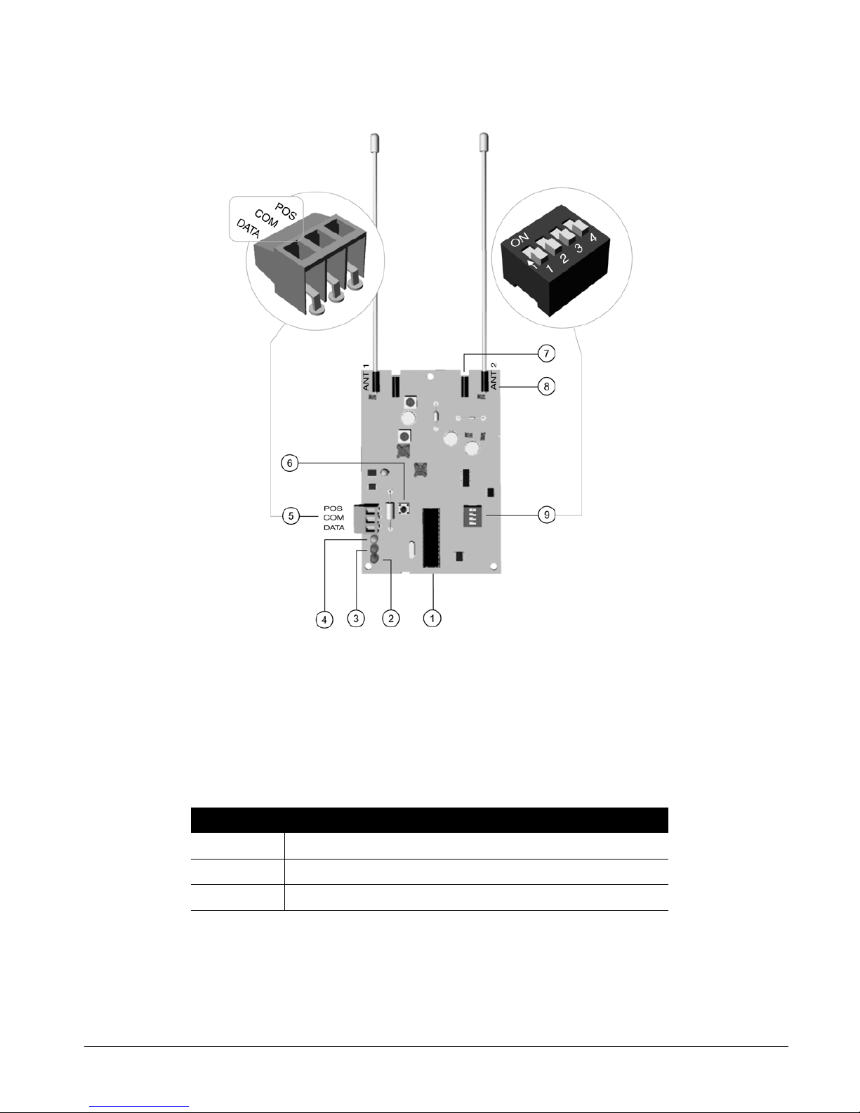
CS875-575-375-275-175 Installers Manual with CS5500 keypad B.5.2
5.2 Installing an RF433 Mhz receiver
5.2.1 Wiring an RF433 Mhz receiver
Wire the RF433 Mhz receiver terminals 5 as follows.
5.2.2 Setting the RF433 Mhz receiver DIP switches
1. Power down the RF433 Mhz receiver.
2. Decide the module number of the RF433 Mhz receiver .
1
Processor
4
Wireless communication LED
7
Not used
2
No function
5
Keypad bus connection
8
Antenna
3
Bus supervision LED
6
Lid tamper
9
DIP switches
Table 5-2: RF433 Mhz receiver terminal connections
Terminal Description
POS Connect to the KP POS terminal of the CSx75. Current draw is 30 mA.
COM Connect to the KP GND terminal of the CSx75.
DATA Connect to the KP DATA terminal of the CSx75.
Page 94

CS875-575-375-275-175 Installers Manual with CS5500 keypadB.5.3
3. Set the DIP switch 9 from Table 5-3: RF433 Mhz receiver DIP switches.
4. Power up the RF433 Mhz receiver.
5.2.3 RF433 Mhz receiver status conditions
When you apply power to the CSx75, the middle (red) LED should start blinking. The LEDs on the receiver
indicate the module status.
The red LED at the bottom of the RF433 Mhz receiver may emit a dim glow but is not used as an indicator
and can be ignored.
For information on installing the RF433 Mhz receiver in the various housings, see chapter A-4 Installing a basic
system.
Table 5-3: RF433 Mhz receiver DIP switches
DIP switch 1-3
settings
RF
receiver
Module
number
DIP switch 1-3
settings
RF receiver Module
number
1 34 5 38
233 6 37
3 32 (default) 7 36
4 39 8 35
= ON = OFF DIP switch 4 is not used
Table 5-4: RF433 Mhz receiver LED indications
LED Module Status
Red blinking
Red off
Normal data communication with the CSx75.
No data communication with the CSx75, check the wiring and power source.
Yellow blinking
Yellow off
Receiving radio signals from learn mode wireless sensors.
No radio signals currently being received.
Page 95

CS875-575-375-275-175 Installers Manual with CS5500 keypad B.5.4
5.3 Installing an RF868 Mhz receiver
5.3.1 Wiring an RF868 Mhz receiver
5.3.2 Setting the RF868 Mhz receiver DIP switches
1. Power down the receiver.
2. Decide the module number of the RF868 Mhz receiver .
3. Set the DIP switch A
from Table 5-6: RF868 Mhz receiver DIP switches.
4. Power up the RF868 Mhz receiver.
1
Jumper setting
5
Wireless communication LED
9
Jumper setting
2
Lid tamper
6
Keypad bus connection
A
Processor
3
Eeprom
7
Not used
B
DIP switches
4
Bus supervision LED
8
Antenna
Table 5-5: RF868 Mhz receiver terminal connections
Terminal Description
DATA Connect to the KP DATA terminal of the CSx75.
COM Connect to the KP GND terminal of the CSx75.
POS Connect to the KP POS terminal of the CSx75. Current draw is 30 mA.
Page 96

CS875-575-375-275-175 Installers Manual with CS5500 keypadB.5.5
Some RX8W8, RX16W8 and RX32W8 receivers have DIP switch labels with On/Off rather than Open/Closed
labels. In the table below you can find both references. The label on the receiver always refers to Open/Close (O/
C).
5.3.3 RF868 Mhz receiver status conditions
When you apply power to the CSx75, the red LED should start blinking. The LEDs on the receiver indicate the
module status.
If you are installing a system in Holland or Belgium, you must use the test antennas RX 9008 when installing
an RF868 system.
For information on installing the RF868 Mhz receiver in the various housings, see chapter A-4 Installing a basic
system.
Table 5-6: RF868 Mhz receiver DIP switches
DIP switch 1-3
settings
RF
receiver
Module
number
DIP switch 1-3
settings
RF receiver Module
number
1 34 5 38
233 6 37
3 32 (default) 7 36
4 39 8 35
= C (ON) = O (OFF) DIP switch 4 is not used
Table 5-7: RF868 Mhz receiver LED indications
LED Module status
Red blinking
Red off
Normal data communication with the CSx75.
No data communication with the CSx75, check the wiring and power
source.
Green blinking
Green off
Receiving radio signals from learn mode wireless sensors.
No radio signals currently being received.
Page 97

CS875-575-375-275-175 Installers Manual with CS5500 keypad B.5.6
5.4 Programming the RF system
5.4.1 Defaulting the wireless modules
You must enroll and default each RF receiver before you begin programming the system.
You must default each module before you start programming it.
1. Navigate with the µ¶ keys to RF Receivers and press OK.
2. Select the relevant module bus ID and press OK. In this case select RF Receiver 32 and press OK.
3. Select Default Settings and press OK.
4. A confirmation message is displayed. Press OK to accept the default settings.
5. The keypad sounder beeps once to confirm the reset.
5.4.2 Programming the wireless detectors
1. Navigate with the µ¶ keys to RF Receivers and press OK.
2. Select the relevant module bus ID and press OK. In this case select RF Receiver 32 and press OK.
3. Scroll to Start Zone and press OK.
4. Enter the starting zone of the receiver . In this case, ente r zone 9 to set zone 9 as the starting zone for receiver
32.
5. Scroll to Learn-in Mode and press OK.
6. To learn-in more than one device, scroll to Sequential Programming, select Yes and press OK.
Model
Version
Default Settings
Internal Reed
External Contact
Receiver Features
Tam per
Jam Detection
Keyfob User ID
Keyfob Low Battery Reports*
Antenna Tamper**
Box Tamper**
Inputs
Enabled
Supervised
Fire Supervision
Keyfob
Keyfob Funct 1
Keyfob Funct 2
Partitions
Door/Window*
Smoke*
Sensor 1
5.1.3
5.1.4
5.1.3.1
5.1.4.1
5.1.4.2
5.1.4.3
5.1.4.4
5.1.3.1.1
5.1.3.1.2
5.1.3.1.3
5.1.3.1.4
5.1.3.1.5
5.1.3.1.6
5.1.3.1.4.1
5.1.3.1.4.3
5.1.3.1.4.2
5.1.3.1.5.1
5.1.3.1.5.2
5.1.3.1.6.1
RSSI Check Zone*
RSSI Value*
Last Round Count**
Supervision
Normal Window
Short Window
Fire Window
RF Signal
5.1.5
5.1.6
5.1.7
5.1.8
5.1.9
5.1.4.5
5.1.5.1
5.1.5.2
5.1.5.3
5.1.6.1
5.1.6.2
5.1.6.3
Sensors 2 - 168
Same as above
Range of se nsors depends
on the number of sensors
and the start zone
number.
*Disabled for 868 Mhz
receivers
*Disabled for 868 Mhz
receivers
* Disabled f or 433 Mhz receivers
**Disable d for 868 Mhz receive rs
* Disabled f or 433 Mhz receivers
** Disable d for 868 Mhz r e ce ivers
Delete
5.1.3.1.7
Start Learning
Start ZoneRF Receiver 32
Learn-in Mode
5.1 5.1.1
5.1.2 5.1.2.1
5.1.2.2
RF Receivers 33 - 39
Same as above
(1) Zone 1
Sequential Programming
5.1.2.1.1
Page 98

CS875-575-375-275-175 Installers Manual with CS5500 keypadB.5.7
7. Scroll to Start Learning and press OK.
8. Enter the zone number to start with. In this case, enter 9 to program the detectors in zones 9 and 10 and press
OK.
5. Tamper the different detectors in sequence. To do this, you activate the sensor’s tamper switch. Table 5-8:
Learning RF sensors explains how to activate each type of sensor.
9. Press ## to leave the programming mode. The OK to Exit prompt is displayed. The system now functions as a
normal alarm system. See the CS5500 LCD Keypad User Manual for information on arming and disarming
the system.
<
Select Installer Menu>RF Receivers>RF Receiver x>Inputs>Sensor x>Delete to delete an enrolled RF zone.
5.4.3 Configuring receiver features
Configurable receiver features include tampers and communication errors. The following example enables RF
jamming detection on RF receiver 32. RF communication is considered to be jammed when there has been a
jamming signal for more than 30 seconds in a 60 second window.
1. Navigate with the µ¶ keys to RF Receivers>RF Receiver 32>Receiver Features and press OK.
2. Scroll to Jam Detection>Enabled and press OK.
3. The keypad beeps once to accept the change and returns to Jam Detection.
5.4.4 Setting supervision windows
There are three wireless supervision options: Short Window, Normal Window and Fire Window. PIR and door/
window sensors follow short and normal windows.
• If a PIR or door/windows sensor does not report within the time specified in Short Window, the system does
not allow the user to arm the system. However, an RF Sensor Lost condition is not reported to the central
station.
• If a PIR or door/windows sensor does not report within the time specified in Normal Window, an RF Sensor
Lost condition is reported to the central station and a service message is displayed on the keypad.
The short and normal window timers are configured differently according to country and frequency. 868 Mhz
transmitters typically report every 15 minutes while 433 Mhz transmitters typically report every 64 minutes.
If you are installing a system in Holland or Belgium, you must set the supervision values to 120 for a long
supervision window. Set the short supervision window in Belgium to 15 and in Holland to 20. Fire transmitter
supervision windows should be set to 240.
When the Arming with Zone Lost option is enabled, the user is always allowed to arm the system even if the PIR
or door/window sensor does not report within the short window.
Smoke detectors follow the fire window. 433 Mhz and 868 Mhz smoke sensors report every 64 minutes. Smoke
detectors follow supervision windows only and report to the central station when not reporting within the fi re
window.
Table 5-8: Learning RF sensors
Transmitter Action
Door/Window Activate the tamper switch by removing the cover.
Door/Window with external contact Activate the tamper switch by removing the cover.
PIR Activate the tamper switch by removing the back plate from the PIR.
Fire detector Press and hold the test button.
Single Button Panic Press and hold the button.
Keyfobs Press and hold the arm and disarm buttons together.
Page 99

CS875-575-375-275-175 Installers Manual with CS5500 keypad B.5.8
5.5 Testing wireless sensors
5.5.1 RF433 Mhz system
The RF433 Mhz system uses a last round count to provide an indication of the quality of the data reception. It
displays the number of rounds of RF data received during the last transmission. The following example tests the
last round count on sensors enrolled on RF receiver 33.
1. Activate a tamper alarm and wait five seconds before resto ring the tamper to prevent additional signals
being counted.
2. Navigate with the µ¶ keys to RF Receivers>RF Receiver 33 and press OK.
3. Scroll to RF Signal>Last Round Count and press OK.
4. The last round count is displayed on the keypad.
5.5.2 RF868 Mhz system
The Remote Signal Strength Indication Value (RSSI) is a measure of the RF reception and is similar to the
indication on a mobile phone. The value is linked to the level of the signal between the wireless sensors and the
RF receiver. On an 868 Mhz system, the RF receiver stores the signal strength of the transmission it receives
from the sensor in a specified zone. The values in this zone are read as follows:
• Values between 1 and 5: The sensor will not work properly and must be moved to another location.
• Values between 6 and 10: The sensor will work but ideally should be moved to another location.
• Values between 11 and 20: These are low values but the sens or will still work properly.
• V alues between 20 and 50: These are normal working values for sensor located at a longer distance from the
receiver.
• Values above 50: Perfect conditions.
RSSI Values may change due to environmental circumstances, for example, additional furniture or metal
constructions. The following example tests the RSSI value of zone 2 on receiver 32.
1. Navigate with the µ¶ keys to RF Receivers>RF Receiver 32 and press OK.
2. Scroll to RF Signal>RSSI Check Zone>(2) Zone 2 and press OK.
3. Open and close zone 2.
4. Scroll to RSSI Value and press OK.
5. The RSSI value is displayed on the keypad.
5.6 Deleting sensors
You can program a receiver to ignore a sensor. This does not remove the sensor identification from the module’s
memory. The sensor can be reactivated later or a new sensor can be learned into the zone. The following
example removes sensor 10 learned in on receiver 32.
1. Navigate with the µ¶ keys to RF Receivers>RF Receiver 32 and press OK.
2. Scroll to Inputs>Sensor 10>Enabled>NO and press OK.
3. The keypad beeps once to accept the change and returns to Enabled.
Page 100

CS875-575-375-275-175 Installers Manual with CS5500 keypadB.5.9
5.7 Glossary
Location Term Definition
5.1 RF Receiver 32 An menu entry that groups all options for the selected RF receiver.
5.1.1 Start Zone
An menu option that specifies the first zone number of zones on the RF
receiver.
5.1.2 Learn-in Mode
An menu option that enables the mode in which a new wireless device is
enrolled on the system.
5.1.2.1 Start Learning An menu command that triggers the learn-in mode.
5.1.2.2 Sequential Programming
An menu option that allows a group of RF sensors to be enrolled in sequence.
Once the first sensor (Start Learning sensor) is configured, the detectors are
learned-in in sequence. The value of ‘Start Learning’ is increased
automatically. This option allows easier programming.
5.1.3 Inputs An menu entry that groups options relating to RF zones only.
5.1.3.1.2 Supervised An menu option that enables supervision of the selected RF sensor.
5.1.3.1.3 Fire Supervision
An menu option that specifies that the RF433 or RF868 receiver uses the fire
supervision timing window.
5.1.3.1.4 Keyfob
An menu entry that groups options relating to any device that sends
commands by a wireless receiver.
5.1.3.1.4.1 Keyfob Funct 1
An menu option that enables the light bulb button on the keyfob for the
selected RF zone on the selected RF receiver. If this option is enabled,
pressing the light bulb button sends a keyfob function 1 event. Control panel
auxiliary outputs and CS507 outputs can be programmed to respond to this
event.
5.1.3.1.4.2 Keyfob Funct 2
An menu option that enables the * button on the keyfob for the selected RF
zone on the selected RF receiver. If this option is enabled, pressing the *
button sends a keyfob function 2 event. Control panel auxiliary outputs and
CS507 outputs can be programmed to respond to this event.
5.1.3.1.4.3 Partitions
An menu entry that lists the partitions assigned to the selected keyfob. The
selected keyfob can trigger an event on these partitions.
A zone may reside in any combination of partitions. A zone that resides in more
than one partition becomes a common zone and is reported to its lowest
partition number. A common zone is armed only when all the partitions that it
belongs to are armed. It is disarmed the moment one of the partitions it
belongs to is disarmed.
5.1.3.1.5 Door/Window
An RF Receiver menu option that configures door/window settings on an RF
433 Mhz receiver. It includes the use of internal reed and additional external
contact of the door/windows transmitters.
5.1.3.1.5.1 Internal Reed
An menu option on an RF door/window sensor that enables the internal reed
contact.
5.1.3.1.5.2 External Contact
An menu option on an RF door/window sensor that enables an additional
external contact. When the external contact is triggered, an alarm is generated
on the same zone number as the door/window sensor (reed contact) itself.
5.1.3.1.6 Smoke An menu entry that groups smoke sensor options.
5.1.3.1.6.1 Tamper An menu option that enables/disables the tamper of a smoke sensor.
5.1.3.1.7 Delete An menu entry that deletes an enrolled RF zone.
5.1.4 Receiver Features An menu entry that groups programmable options for RF receivers.
5.1.4.1 Jam Detection A menu option that enables the detection of RF jamming.
 Loading...