

Page 1
SENTROL
AP633/AP643
Passive Infrared Detectors
Installation Instructions
INTRODUCTION FEATURES
The AP633 and AP643 offer the detection of motion for
infrared targets in selectable ranges extending 40 ft., 80 ft.
and 200 ft.(12 m, 24 m, and 60 m). The detector’s sensitivity
may be programmed to suit most environmental applications. Aritech’s traditional viewing angle selection (mirror
blocking) allows the installer to select and delete any portion
of the coverage pattern to customize the optical performance
of the unit. In addition, the mounting plate of the sensor is
equipped with precise adjusting screws to allow the installer
to alter the horizontal viewing point as much as 2 degrees to
the left or right, above or below the unit. These features
combine to make this passive infrared sensor the most stable
detector available for commercial and industrial installation
needs in the security industry today. The more sophisticated
model AP643 enhances standard operation with options
such as alarm memory, unit to unit double check, eye to eye
check, and first in alarm indication as well as remote control
of the walk test mode.
SPECIFICATIONS
Input Power....................................................... 9.5 –15 V DC
Peak to Peak Ripple ................................... 2 V max. (@12V)
Current Consumption ................... 20mA Nominal 35mA Max
Contact Rating.............................Alarm–100 mA @ 28 V DC
Tamper–100 mA @ 28 V DC
Coverage Pattern ........12 selectable patterns using snap-on
blockers (see last page for patterns)
Mounting Height ....................... 6 ft. to 10 ft. (1.8 m to 3.0 m)
Environmental Limitations .. 0°F to +131°F (–18°C to +55°C)
Dimensions ..................................6.30 in. x 4.13 in. x 2.95 in.
(160 mm x 105 mm x 75 mm)
T
S
I
L
U
N
D
E
R
U
W
R
I
T
L
E
R
S
L
A
B
LISTED
• Integral Coverage 200 ft. max. (60 m)
• Precision Mirror Optics
• Step Focus Curtain
• 12 Different Protection Patterns
• Form C Contacts
• Calibrated Sensitivity
• Measures And Adjusts To Temperature Changes
• UL and ULC Listed
AP643 Additional Features
• Eye To Eye Checker Mode
• First To Alarm Memory
• Programmable Double Checker Mode
• Remote Control Of Walk Test LED
• UL and ULC Listed
DETECTION HAZARDS
Planning Installation of the Unit:
Avoid these sources of disturbance:
• Sunlight or vehicle headlights shining directly onto the
detector.
• Heat sources or mobiles in the field of view.
• Strong air drafts blowing onto the detector.
• Animals in the field of view.
• Insects in the housing or on the face of the unit.
• Objects or circumstances which may cause rapid
temperature changes in the field of view.
• Very strong sources of RF energy and induction of
electrical noise.
D
E
B
Y
A
D
A
N
A
C
F
O
S
E
I
R
O
T
O
A
R
Page 2
MOUNTING TIPS
SENSOR HOOKUP
• This sensor is for interior applications only.
Do not mount outside.
• Do not block the viewing angle of the sensor.
• Mount this and all passive infrared sensors so that would
be intruders will cross the pattern of detection at 90°
(or as close to 90° as possible).
• Seal all openings and cable entries.
• When mounting sensor on masonry surfaces use appropriate moisture barrier.
• Use of the vertical adjustment screw may result in a
reduction of range.
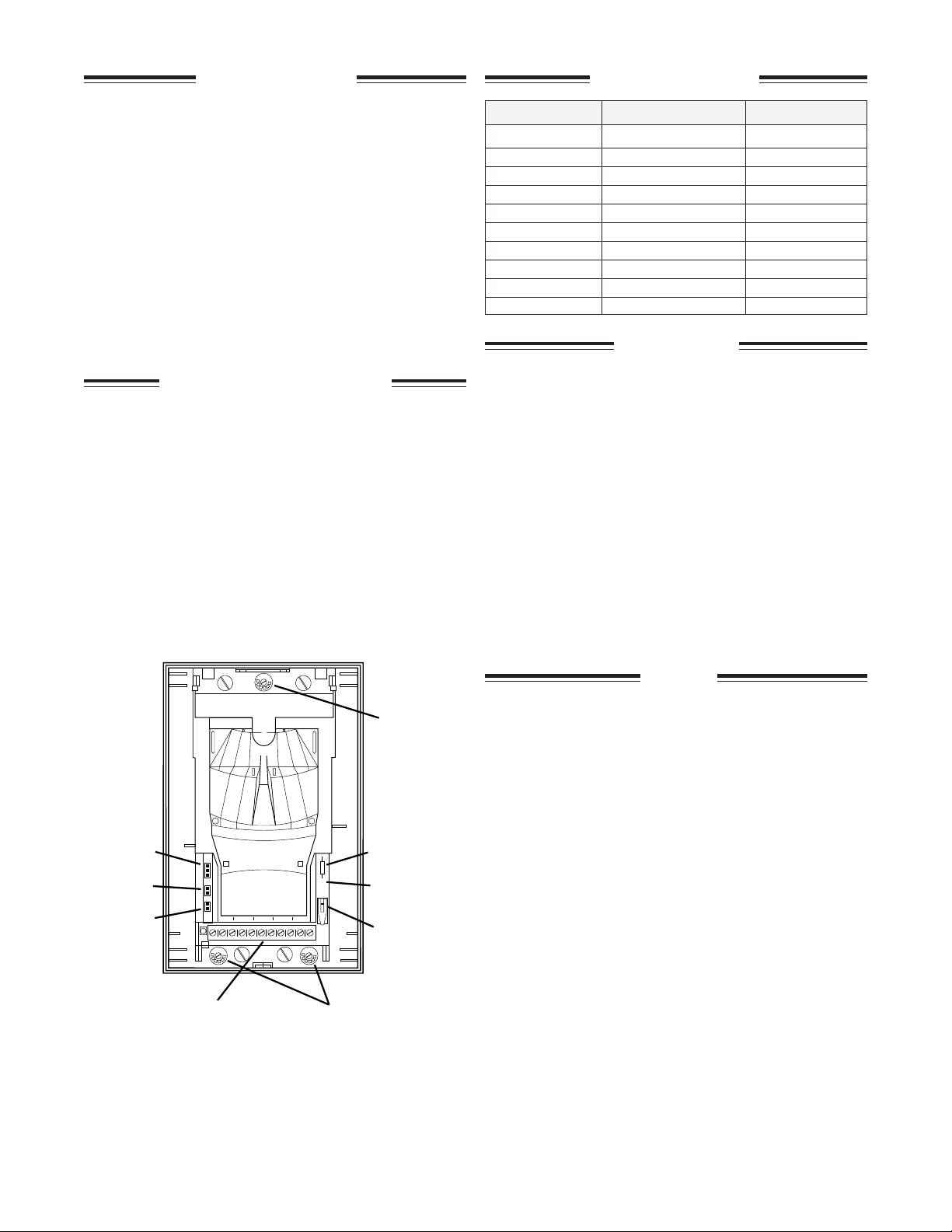
MOUNTING THE SENSOR
The ideal mounting height for this sensor is 6 ft. to 10 ft.(1.8
m to 3.0 m). Loosen the retaining screw and lift the front
cover off of the unit. Using an awl or similar punch type
device, remove the necessary knockouts and create a path for
the cables to enter the backplate. Remove only those
knockouts which you plan to use. Pull cable through the
entries and level the backplate on the wall. Mark the screw
holes and insert 8-32 x 2 inch screws and tighten until
secure. Be careful not to over-tighten the backplate as you
may wish to adjust the viewing angle after walk testing. It is
important to leave a 1/2 inch clearance space between the top
of the sensor and any surfaces above it (i.e. ceiling, shelves
or cabinets, etc.). This will allow the cover to be replaced
with ease.
TERMINAL AP633 AP643
#1 (–) Negative (–) Negative
#2 (+) Positive (+) Positive
#3 N.C. Contact N.C. Contact
#4 Common Common
#5 N.O. Contact N.O. Contact
#6 Tamper N.C. Tamper N.C.
#7 Tamper N.C. Tamper N.C.
#8 Spare (not used) Spare
#9 N/A Alarm Latch
#10 N/A Walk Test
USAGE TIPS
Both units are equipped with a Form C alarm initiation
circuit (Terminals 3,4, and 5) and a closed loop tamper
circuit (Terminals 6 and 7). The installer may wire these
circuits in series if desired. If the control panel requires class
B supervision, the spare terminal (# 8) may be used to
anchor the EOL device. This allows the installer to place the
EOL device in the sensor without the use of splice connectors. Some of the advanced detection features of the AP643
(discussed later) require an additional switched voltage from
the control. If the protective loop and the control panel
power supply share a common negative, both may use the
same conductor. This will free up a single conductor for use
in one of the advanced features.
Detectors must be connected to a UL listed control or
power supply which will provide a minimum of four
hours standby power.
Jumper A
Jumper B
Jumper C
#2 to #10 Jumper
Factory Installed
AP643
Terminal 9 requires a +12 V DC input during the armed
Viewing Angle
Adjustment
(tighten or
loosen screw to
adjust)
cycle to latch the LED of any violated detectors. Terminal 10
requires a +12 V DC input while the walk test LED response
is desired. The unit has a factory installed jumper at Terminals 2 and 10. This jumper must be removed if any of the
advanced detection (Alarm Memory, First to Alarm, etc.)
features are to be used.
Eye to Eye
Jumper
A
B
C
2
8
1046
(AP643 Only)
Jumper D
(AP633 only)
Tamper
Notes:
1. The AP633 uses pin jumper D to enable/disable the walk
test LED. The pin cover connects to both pins to enable
this feature.
2. This unit uses a 33Ω (ohm) current limiting resistor for
transient protection on the protective loop. It is important
to consider this value when calculating loop resistance.
Viewing Angle
Adjustment
Page 3

SENSITIVITY
The sensor uses a unique signal processing method known as
Dynamic Data Discrimination. “4D” allows the sensor to
analyze the size and shape of a waveform produced in the
detector and determine whether the signal is generated by an
intruder or an environmental source. The sensor has three
field changeable settings of sensitivity for “4D”: High
Sensitivity, Increased Sensitivity and Standard Sensitivity.
The installer may select standard sensitivity by moving the
pin connector of jumper A to cover the lower two (2) of the
three (3) pins. High sensitivity is selected by inserting the pin
connector in such a way that it only makes contact with one
of the three (3) pins of jumper set A. Increased sensitivity is
selected by inserting the pin connector of jumper set A so
that the upper two (2) pins are covered.
Standard Sensitivity should be selected for normal and all
40-foot-wide angle applications. For use with patterns E,
G, and H only.
High Sensitivity should only be used in hazard free, high
security applications. For use with patterns A through L.
Increased Sensitivity should be used in 80-foot-wide angle
areas, 40-foot curtain only or long range applications. For
use with patterns A through L.
ZONE LOCATION TESTING
This sensor is equipped with a test feature which goes
beyond walk testing and allows the installer to identify
exactly each zone of coverage. This advantage allows the
installer to avoid splitting a zone of coverage between two
areas of dissimilar background infrared energy levels, such
as a metal door and a freezer. By inserting the pin connector
so that both of the pins in jumper set B are covered, the zone
location test mode is active. After activating this mode, walk
without stopping across the coverage pattern and observe the
sensor. Each time the green LED illuminates, you enter a
zone. If the green LED goes out, you are in the center of a
zone (between two pyroelectric elements) or you are between
two zones. By connecting the armed output of the control
panel (+12 VDC) to Terminal 9 of all detectors connected on
this run (up to 40 units), the LED will latch in alarm any and
all sensors which were activated during the armed period.
After determining all zone locations, return to the normal
mode by inserting the pin connector so that the two pins of
jumper set B are not connected.
ALARM MEMORY SETTING–AP643
By connecting the armed output of the control panel
(+12 VDC) to Terminal 9 of all detectors connected on this
run (up to 40 units), the LED will latch in alarm any and all
sensors which were activated during the armed period.
The jumper from Terminal 2 to Terminal 10 must be
removed after walk test to enable this feature.
FIRST TO ALARM SIGNAL–AP643
An added feature to the Alarm Memory Setting is the First to
Alarm Signal. By connecting Terminal 10 of the first sensor
on the run to Terminal 10 of subsequent sensors, as well as
wiring described in Alarm Memory Setting, the first unit
activated in an armed cycle will indicate activation by
flashing. Subsequently activated sensors will annunciate by a
solid indication on the walk test LED.
The jumper from Terminal 2 to Terminal 10 must be
removed after walk test to enable this feature.
FIRST TO ALARM INDICATION–AP643
Z1100 J-16 #8 (Yellow) Through Auxiliary Relay
1st
Control
+12 V
Armed Output
Apply on arming system
Remove on disarming
NOTE: Avoid viewing customer exit path with this application
#9
#10
2nd 3rd 4th
Up to 40 Sensors
DOUBLE CHECKER MODE–AP643
The Double Checker Mode is a special discrimination
method in which a valid alarm signal will be given only
when a minimum of 2 detectors have recognized an event or
when the same sensor detects 2 events within a specific time
frame. This feature will allow the installer to station 2 or
more detectors in a premises along a projected path of
intrusion. Should the sensors see any 2 events within a 2
minute time period then the violated sensors will activate
the control panel. To select this mode of operation, insert
the pin connector of jumper set C so that both pins are
disconnected. (Wire same as First to Alarm Indication).
Not for use in UL installations.
Settings: Increased sensitivity, walk test off, eye to eye
not cut, jumper 2 to 10 removed.
EYE TO EYE CHECKER–AP643
In extremely hazardous environments or installations
requiring absolute accuracy of an alarm, dual detector
verification may be desired. By cutting a special compo-
nent on the sensor and aligning the viewing angle of 2
sensors so that they view a common area, the sensors will
only activate the control if both share a violation within a
short time frame (10 sec.). This offers an unparalleled
accuracy of detection. An intruder must violate the coverage
pattern that the 2 sensors share in common. (Wire same as
First to Alarm Indication).
For use in UL installations, protection patterns must
overlap and provide detection by both sensors per UL
standard walk test procedures.
Settings: High or increased sensitivity, walk test off,
double checker off, eye to eye on.
ALARM MEMORY WIRING
Z1100 J-16 #8 (Yellow) Through Auxiliary Relay
Control
+12 V
Armed Output
Apply on arming system
Remove on disarming
NOTE: Avoid viewing customer exit path with this application
1st
#9
#10
Up to 40 Sensors
2nd 3rd 4th
EV on.
EV on.
curtain
EV off.
TEST off.
TEST on.
CHECKER off.
CHECKER on.
A 1
A 2
A 3
B 4
B 5
C 6
C 7
A
B
C
21046
8
EYE TO EYE off.
EYE TO EYE on.
D8
D9
Page 4

REMOTE CONTROL OF WALK TEST LED
1
4
6
If your control panel provides a switchable +12 V output which can be activated and de-activated by the user or installer, this
can be used as the ‘walk test enable’ as shown. Select a timed access (through auxiliary relay) output from the Z1100 System
1 or System E for this feature.
Control
+12 V
#9
#10
2nd 3rd 4th
1st
Up to 40 Sensors
Walk test is active as long as +12 V is present.
Link between terminals 2 and 10 must be removed.
PATTERN OPTIONS AS VIEWED BY THE SENSOR
Removes Right 40 ft., Wide Angle Pattern ➀
Removes Left 40 ft., Wide Angle Pattern ➁
Removes Left 80 ft., Wide Angle Pattern ➂
12
3
4
Removes Right 80 ft., Wide Angle Pattern ➃
Removes 80 ft. Center Pattern Only ➄
Removes 200 ft. Long Range Pattern Only ➅
INSTALLATION NOTE: Be certain to locate field of view
carefully for required detection. As with all PIR sensors, there is
no detection between fields of view. Installation must be tested
one or more times yearly.
Example of factory setting
A
6
40 ft. 80 ft.
D
B
2
1
4
3
6
E
2
3
4
3
5
6
40 ft. 80 ft.
G
1
4
3
H
5
6
40 ft.
J
K
6
2
4
3
5
6
40 ft. 80 ft.
40 ft.
40 ft.
C
F
I
L
5
6
Curtain Pattern
2
1
4
3
5
6
40 ft. 80 ft.
40 ft.
40 ft. 80 ft. 200 ft.
2
1
4
3
40 ft. 80 ft. 200 ft.
The unit is to be connected to a UL Listed power supply or control unit capable of providing a minimum 4 hours of standby power.
The equipment should be installed in accordance with NFPA 70. The unit shall be tested at least once a year.
CORPORATE HEADQUARTERS
12345 SW Leveton Dr.
Tualatin, OR 97062
Tel.: 503.692.4052 F ax: 503.691.7566
U.S. & Canada: 800.547.2556
Technical Service: 800.648.7424
SENTROL
FaxBack: 800.483.2495
1
4
40 ft. 80 ft. 200 ft.
2
3
40 ft. 80 ft. 200 ft.
Sentrol reserves the right
to change specifications
without notice.
©1998
P–3412-0398
15597 Rev A
 Loading...