

Page 1
*(6HFXULW\
)
ZZZJHVHFXULW\FRP
Part No:
60-875
60-910 (Not investigated for use by UL)
600-1012
466-1873-01 Rev B
July 2004
Disarm
Lights
System
Status
On OffSensorMotion Time
AUX
H O M E S E C U R I T
9 / 05 / 63 / 4 7 / 81 / 2
H O M E C O N T R O L
E M E R G E N C Y
Y
C O D E
Doors
Chim
Doors &
Windows
e
Bypass
Arm
Motion
Sensors
Test Weekly
POLICEFIRE
Simon Security
System
Installation Instructions
Page 2
FCC Notices
FCC Part 15 Information to the User
Changes or modifications no t ex pre ssly a pproved by GE Security can voi d the user’s authority to operate the eq ui pm ent.
FCC Part 15 Class B
This equipment has been tested and found to comply with the limits for a Class B digital device, pursuant to part 15 of the FCC Rules. These limits are designed
to provide reasonable prote ct io n against interference in a reside ntial installation.
This equipment generates, uses, and can radiate radio frequency energy and, if no t in stalled and used in accordance w it h the instructions, may cause harmful
interference to radio communications. However, there is no guarantee that interference will not occur in a particular installation.
If this equipment does cause harmful interference to radio or television reception, which can be determined by turning the equipment off and on, the user is
encouraged to try to correct the interference by one or more of the following me asures:
• Reorient or relocate the receiving antenna.
• Increase the sep a r ation between the equipment and receiver.
• Connect the af f ected equipment and th e panel receiver to sep arate outlets, on di fferent branch ci r cuits.
• Consult the dealer or an ex perienced radio/TV technician for help.
FCC ID: B4Z-787E-SIMON
ACTA Part 68
This equipment comp lies with Part 68 of the FCC Rule s. Located on this equipment is a label that contains, among other informat ion, the FCC registration number and the ringer equivale nc e number (REN) for this eq uipment. If requested, this information must be provi de d to t he telephone company.
FCC Part 68 Registration No. B4ZUSA- 27621-AL-E REN: 0.2B
The REN is used to determine the maximum number of devices that may be connected to your telephone line. Excessive RENs on a telephone line may result in
devices not ringing in response to an inc o m in g ca ll . In mo st are as, the sum of all device REN s sh ould not exceed five (5.0). To be certain of the number of
devices that may be connected to a line, as determined by the total RENs, contact the local telephone company. For products approved after July 23, 2001, the
REN for this product is part of the product identifier that has the format US:AAAEQ##TXXXX. The digits represented by ## are the REN without a decimal
point (e.g., 03 is a REN of 0.3). For earlier products, the REN is separately shown on the label.
A plug and jack used to connect thi s equi pment to the premises wiring an d te le phone network must comply with the applicable FCC Part 68 rules a nd re qui rements as adopted by ACTA. A compliant telephone cor d and modular plug is provided with this product. It is designed to be c onnected to a compliant modular
jack that is also complian t. See the Installation In s tr uctions for d etails.
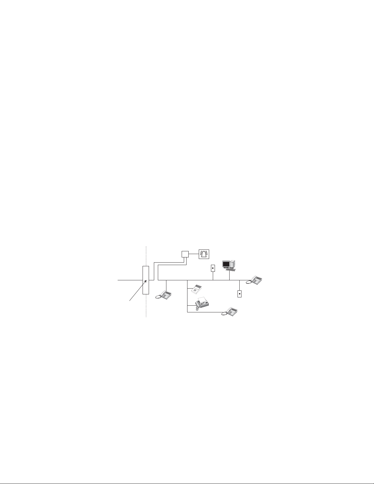
Alarm dialing equipme nt must be a ble to se iz e the telephone line and pla ce a ca ll in an emergency situation. It m ust be able to do this even if other equ ipment
(telephone, answering system, c om puter modem, etc.) alre ady has the telephone line in use. To do so, alarm dialing equipm e nt m ust be connected to a properly
installed RJ31X jack that is electr i cally in series an d ahead of all other eq uipment attached to the same telephone line. Proper installation is depicted in the following diagram. If you have any questions concerning these instructions, consult your local telephone company or a qualified installer about installing an RJ31X
jack and alarm dialing equipment for you.
C u s t o m e r P r e m i s e s E q u i p m e n t a n d W i r i n g
N e t w o r k
S e r v i c e
P r o v i d e r ' s
F a c i l i t i e s
T e l e p h o n e
L i n e
N e t w o r k
D e m a r c a t i o n
P o i n t
T e l e p h o n e
R J 3 1 X
J a c k
If this equipment causes harm to the telephone network, the teleph one com pa ny may temporarily disconn ec t yo ur service. If possible, you will be notified in
advance. When advance notice is not practical, you will be not ifi ed as soon as possible. You will also be advised of your right to file a complaint with the FCC.
The telephone comp any may make changes in its facilities, equipment, ope rations, or procedures that could affect the operation of th e equipment. You will be
given advance notice in order to maintain uninterrupted service.
If you experience trouble with this equipment, please contact the company that installed the equipment for service and/or repair information. The telephone company may ask you to disconne ct this equipment from the net w ork until the problem has been corre cted or you are sure that the eq ui pment is not malfunct ioning.
This equipment may no t be us ed on coin service provided by the telephone compa ny. Connection to party lines is subject to state tariffs.
Patent Information
This product and the use of this product may be covered by one or more of the following patents: 5,805,063, 5,872,512, 5,942,981, 5,686,896, 5,686,88 5,
4,855,713. Except expressly provided herein, the purchase of this product shall not constitute a license or otherwise provide a right to practice a method cover ed
by any of the identified pate nts. GE Security hereby grants the purchaser of this product a limited, non-exc lu s ive li cense to practice the meth od s p atented in the
identified patents solely with products manufactured, sold or licensed by GE Security. This license grant do es not extend to the use of unlice nse d, thi rd party
products with this product.
U n u s e d
R J - 1 1 J a c k
A n s w e r i n g
S y s t e m
A l a r m D i a l i n g
E q u i p m e n t
F a x M a c
h i n e
T e l e p h o n e
C o m p u t e r
U n u s e d
R J - 1 1 J a c k
T e l e p h o n e
Page 3

Canada Notice
all
)
The Canadian Department of Communications label identifies certified equipment. This certification means that the equipment meets certain telecommunications network protec ti ve, operational, and safet y requirements. The depart ment does not guarantee the equipment will ope rate to the user’s satisfaction.
Before installing this equipment, users should ensure that it is permissible to be connected to the facilities of the local telecommunications company. The
equipment must also be installe d usi ng a n acceptable method of conn ection. In some cases, the company’s inside wiring associated with a single-line i ndi vidual service may be extended by means of a certified connector assembly (telephone extension cord). The customer should be aware that compliance with
the above conditions may n ot prevent degradation of service in som e situ ations.
Repairs to certified equipment should be made by an auth orized Canadian mainte nance facility designated by th e supplier. Any repairs or alterations made
by the user to this equipment, or equipment malfunctions, may give the telecommunications co mpan y cause to reque st the u ser to dis connect the e qu ipment.
For your protection, make sure that the electrical ground connections of the power utility, telephone lines, and internal metallic water pipe system, if present,
are connected together
Do not attempt to make connections yourself. Contact the appro priate electrician or elec-
!
Caution
The Load Number (LN) assigned to each terminal device denotes the percentage of the total load to be connected to a telephone loop which is used by the
device, to prevent ov erl oading. The terminat ion on a loop may consist of an y combination of devic e s sub je ct only to the requirement that the total of the
LNs of all the devices does not ex ce ed 100. Load Nu m b er: .1 The t e r m “IC:” before the certificat io n/registration n umber onl y s ignifies tha t the Industr y
Canada technical specifications were met. IC: 867 A 787SIMON
“AVIS: - L ´étiquette du ministère de s Com m unications du Canada identifi e le matériel homologué. Cette étiquette certifie que le matériel est conforme a
certaines normes de protection, d ´ exploitation et de sécurité des réseaux de télécommunications. Le ministère n ´ assure toutefois pas que le matériel fonctionnera a la satisfacti on de l ´ uti li s at eur.
Avant d ´ installer ce matériel, l ´ utilisateur doit s ´ assurer qu´ il est perm i s de le rac corder aux installations de l ´ enterprise locale de télécommunication.
Le matériel doit également etre installé en suivant une méthod acceptée de raccordement. Dans certains cas, les fils intérieurs de l´ enterprise utilisés pour
un service individuel a ligne uni que peuvent etre prolongés au moyen d´ un dispositif homologué de ra ccordement (cordon prol ongateur téléphonique
interne). L ´ abonné ne doit pas oublier qu ´ il est possible que la conformité aux conditions énoncées ci-dessus n ´ empechent pas le dégradation du service
dans certaines situations. Actuellement, les enterprises de télécommunication ne permettent pas que l ´ on raccorde leur matériel a des jacks d ´ abonné, sauf
dans les cas précis prévus pas les tarrifs particuliers de ces enterprise s.
Les réparations de matériel homologué doivent etre effectuées pas un centre d ´ entretien canadien autorisé désigné par le fournisseur. La compag ne de télécommunications peut dem a nder a l ´ utilisateur de débranche r un appareil a la suite de réparations ou de modifications effectuées par l ´ utilisateur ou a
cause de mauvais fonctionnem ent.
Pour sa propre protection, l ´ utilisateur doit s ´ assurer que tous les fils de mise a la terre de la source d ´ énergie électrique, des lignes téléphoniques et des
canalisations d ´´ eau métalliques, s ´ il y en a, sont raccordés ensemble. Cette précaution est particulièrement importante dans les régions rurales.
Avertissment. - L ´ utilisateur ne doit pas tenter de faire ces raccordements lui-meme; il doit avoir recours a un service d ´ inspection des installations électriques, ou a electricien, selon le cas”.
Une note explicative sur les indices de charge (voir 1.6) et leur emploi, a l ´ intention des utilisateurs du matériel terminal, doit etre incluse dans l ´ information qui accompagne le ma te riel homologué. La not e pourrait etre rédigée sel on le modèle suivant:
“L ´ indice de charge (IC) assigné a chaque dispositif terminal indique, pour éviter toute surcharge, le pourcentage de la charge totale qui peut etre raccordée
a un circuit téléphonique bouclé utilisé par ce dispositif. La terminaison du circuit bouclé peut etre constituée de n ´ import somme des indices de charge de
l ´ ensemble des dispositifs ne dépasse pas 100.”
L ´ Indice de charge de cet produi t est ____________.
tric inspections authority.
DO NOT change Option 56 from its default if the customer doesn’t have c
*(6HFXULW\
*(6HFXULW\6LPRQLVDUHJLVWHUHGWUDGHPDUNRI*(6HFXULW\$OORWKHUWUDGH
PDUNVDUHSURSHUWLHVRIWKHLURZQHUV
$OOULJKWVUHVHUYHG
5HG)R[5RDG
$UGHQ+LOOV01
7HFKQLFDO6XSSRUW
Page 4

Contents
About This Manual 1
Special Installation Requirements ................................................................................................ ... ........... 1
Planning the Installation 4
Standard Panel...................................... .... .... ......................... ..................................................................... 4
System Overview 4
System Components................................................................................................................................... 4
Planning Sensor Types & Locations 7
Device Locations.......................................................................................................................... ... .... ....... 7
X10 Modules...................................................................................................................... ......................... 8
UL Listed Installations.... .......................... ............................................... ......................... ...................... 1
SIA System Requirements...................................................................................................................... 2
Central Station Reporting ....................................................................................................................... 3
UL Canada Listed Installations........................................................................................................ ... .... 3
California State Fire Marshall Listed Installations................................................................................. 3
Control Panel...................... ... ................................................ ............................................... .... ... ........... 4
System Devices................................................................................................................................... .... 5
Control Panel...................... ... ................................................ ............................................... .... ... ........... 7
Remote Handheld Touchpad................................................................................................................... 8
QS1500 Keypad.................................................................................................................... .................. 8
Keychain Touchpad................................................................................................................................ 8
Dialog Telephone Interface Module....................................................................................................... 8
House Code and Unit Numbers....................................................................................................... ... .... 8
Manually Controlling Lights .................................................................................................................. 8
Installing the System 9
Materials Needed........................... .......................... ............................................... ......................... .... ... .... 9
Opening the Panel Cover and Chassis........................................................................................................ 9
Mounting the Panel................................................................................................................................... 10
Wall Mounted Panel.............................................................................................................................. 10
Tabletop Mounted Panel....................................................................................................................... 10
Connecting Hardwire Devices.................................................................................................................. 11
AC Terminals........................................................................................................................................ 11
HWIN1, HWIN2, and DCOUT Terminals........................................................................................... 11
Wiring Interior Sirens............................................................................................................................... 11
LD105 Hardwire Interior Siren............................................................................................................. 12
Wiring Exterior Sirens.............................................................................................................................. 12
Hardwire Exterior Siren with Supe rv is ion ... .... ......................... ................................................ ............ 12
Hardwire Exterior Siren withou t Supe rv isio n................... ......................... .......................... ................ 13
Wiring Hardwire Contacts........................................................................................................................ 13
Wiring a Phone Line to the Panel............................................................................................................. 13
Full Line Seizure................................................................ ......................... .......................................... 14
i
Page 5

No Line Seizure.................................................................................................................................... 15
Wiring the Power Transformer................................................................................................................. 15
Powering Up the Panel ............................................................................................................................. 15
Installing the Panel Backup Battery...................................................................................................... 15
Applying AC Power.............................................................................................................................. 16
Installing X10 Modules.............................................. ............................................... ............................... 16
Lamp and Appliance Modules.............................................................................................................. 16
Universal Module................................................................................................................................. 16
Sensor Installation.... .... ............................................... ............................................... ............................... 17
Programming 17
Entering Program Mode...... .... ............................................... ......................... .......................................... 17
Exiting Program Mode.............................................................................................................................. 17
Reset Memory to the Factory Defaults..................................................................................................... 17
Set the Clock.................................. .... ......................... ............................................... ............................... 17
Adding (Learning) Sensor s...................................................................... ................................................. 18
X10 Module Operation............................................................................................................................. 20
Ethernet Interface Module........................................................................................................................ 21
Requirements........................................................................................................................................ 21
Activate the Ethernet Interface Module................................................................................................ 21
Numbered Options.................................................................................................................................... 22
Option 01: Panel Piezo Beeps............................................................................................................... 22
Option 02: Panel Voice......................................................................................................................... 23
Option 03: Latchkey ............................................................................................................................. 24
Option 04: Primary Phone Number...................................................................................................... 24
Option 05: Secondary Phone Number.................................................................................................. 25
Option 06: Downloader Phone Number............................................................................................... 25
Option 07: Account Number................................................................................................................. 25
Option 08: Phone Lock......................................................................................................................... 26
Option 09: Downloader Code............................................................................................................... 26
Option 10: Entry Delay......................................................................................................................... 26
Option 11: Exit Delay........................................................................................................................... 27
Option 12: Phone 1 Reports.................................................................................................................. 27
Option 13: Phone 2 Reports.................................................................................................................. 27
Option 14: DTMF Dialing.................................................................................................................... 28
Option 15: No Activity Timeout........................................................................................................... 28
Option 16: Auto Phone Test.................................................................................................................. 29
Option 17: Dialer Delay........................................................................................................................ 29
Option 18: Alarm Cancel Report .......................................................................................................... 29
Option 19: RF Timeout......................................................................................................................... 30
Option 20: Manual Phone Test ............................................................................................................. 30
Option 21: Opening Reports................................................................................................................. 30
Option 22: Closing Reports.................................................................................................................. 31
Option 23: Force Armed Report........................................................................................................... 31
Option 24: AC Power Failure Report................................................................................................... 31
Option 25: CPU Low Battery Report ................................................................................................... 32
Option 26: Fail to Communicate.......................................................................................................... 32
Option 27: Ring/Hang/Ring.................................................................................................................. 32
Option 28: No Delay from Keychain Touchpad................................................................................... 33
Option 29: Panel Piezo Alarms............................................................................................................. 33
Option 30: Panel Panic Alarms............................................................................................................. 34
Option 31: Downloader Enable............................................................................................................ 34
ii
Page 6

Option 32: 300 Baud............................................................................................................................. 34
Option 33: Audio Verification.............................................................................................................. 35
Option 34: Fail to Open Report..................................................................................... ....................... 35
Option 35: Fail to Close Report............................................................................................................ 35
Option 36: Sensor Activated Light Lockout Start Time....................................................................... 36
Option 37: Sensor Activated Light Lockout Stop Time....................................................................... 36
Option 38: Auto Arm............................................................................................................................ 37
Option 39: Siren Timeout..................................................................................................................... 37
Option 40: Trouble Beeps..................................................................................................................... 38
Option 41: Chime Voice ....................................................................................................................... 38
Option 42: Speaker Level..................................................................................................................... 38
Option 43: Numeric Pager/Voice Event Notification Phone Number.................................................. 39
Option 44: Numeric Pager/Voice Event Notification Phone 3 Reports................................................ 39
Option 45: Sensor Alarm Restoral Report............................................................................................ 40
Option 46: Fire Shutdown - AVM ........................................................................................................ 40
Option 47: AVM Mode......................................................................................................................... 41
Option 48: Panic Talk - AVM............................................................................................................... 41
Option 49: Arming LEDs Shutdown.................................................................................................... 41
Option 50: RF Jam Detect .................................................................................................................... 42
Option 51: 24 Hour Sensor Tamper...................................................................................................... 42
Option 52: Unvacated Premises............................................................................................................ 42
Option 53: Hardwire Siren Supervision................................................................................................ 43
Option 54: Access Code Length........................................................................................................... 43
Option 55: Status Beep Volume............................................................................................................ 44
Option 56: Call Waiting........................................................................................................................ 44
Option 57: Supervisory/Tamper Report................................................................................................ 44
Option 58: Remote Touchpad Arming.................................................................................................. 45
Option 59: Exit Extension .................................................................................................................... 45
Option 60: Secure Arming.................................................................................................................... 45
Option 61: Demo Mode........................................................................................................................ 46
Option 62: Supervisory Protest............................................................................................................. 46
Option 63: 24 Hour Time...................................................................................................................... 46
Option 64: No Arm on Panel Low Battery........................................................................................... 47
Option 65: No Usage Report ................................................................................................................ 47
Option 66: External Siren Delay........................................................................................................... 47
Option 67: Quick Exit........................................................................................................................... 48
Option 68: Swinger Shutdown.............................................................................................................. 48
Option 69: SIA Limits.......................................................................................................................... 48
Option 70: Not Available...................................................................................................................... 49
Option 71: Programming Report.......................................................................................................... 49
Option 72: Supervisory Time................................................................................................................ 49
Option 73: Modem Sensitivity.............................................................................................................. 50
Option 74: Silent Panel Police Panic.................................................................................................... 50
Option 75: VOX Mic Gain................................................................................................................... 50
Option 76: VOX Gain Range................................................................................................................ 51
Option 77: Manual Mic Gain................................................................................................................ 51
Option 78: VOX Receiver Gain............................................................................................................ 51
Option 79: Panel Cover Tamper ........................................................................................................... 52
Option 80: Alarm Report Verification .................................................................................................. 52
Option 81: Heating Set Point................................................................................................................ 52
Option 82: Cooling Set Point................................................................................................................ 53
Option 83: X10/RF Light Control ........................................................................................................ 53
iii
Page 7

Option 84: European Compliance......................................................................................................... 53
Option 85: Smoke Supervision............................................................................................................. 53
Option 86: Fire Alarm Verify................................................................................................................ 54
Option 87: 2-Way RF Touchpad Voice................................................................................................. 54
Option 88: Custom Defaults................................................................................................................. 54
Option 89: Serial Port Protocol............................................................................................................. 54
Option 90: Comm Channel 1 Reports .................................................................................................. 55
Option 91: Comm Channel 2 Reports .................................................................................................. 55
Option 92: Comm Channel 3 Reports .................................................................................................. 55
Option 93: DTIM Reports Phone 1....................................................................................................... 56
Option 94: DTIM Reports Phone 2....................................................................................................... 56
Option 95: Not Available...................................................................................................................... 56
Option 96: HWIN2 Output Function.................................................................................................... 57
Option 97: HWIN1 Output Function.................................................................................................... 57
Programming System Access Codes........................................................................................................ 57
Testing the System 58
Control Panel...................... .... ............................................... ................................................................... 58
Sensor Testing................................ .... ............................................... ........................................................ 59
Improving Sensor/Panel Communication................................................................................................. 61
Antenna................................................................................................................................................. 61
If a Sensor Fails the Sensor Test........................................ .... ... .......................... .................................. 61
Phone Communication.............................................................................................................................. 61
Off-Site Phone Operation ......................................................................................................................... 62
Central Station Communication................................................................................................................ 62
Dialog Telephone Interface Module (DTIM)........................................................................................... 63
Pager Communication............................................................................................................................... 63
2-Way Voice Operation............................................... ............................................... ............................... 64
Voice Event Notification........................................................................................................................... 65
RF Thermostat Operation ......................................................................................................................... 65
Personal Help Button....................................... .... .... ......................... ......................... .... ........................... 65
X10 Operation........................................................................................................................................... 65
Manual Lamp Module Control............................................................................................................. 65
X10 Siren and Lamp Module Functions............................................................................................... 66
Emergency Planning 66
Appendix A: 68
Troubleshooting........................................................................................................................................ 68
System Status........................................................................................................................................ 68
Control Panel...................... ... ................................................ ............................................................... 68
Options (Programmable by the homeowner)........................................................................................ 68
Sensors.................................................................................................................................................. 68
X10 Modules......................................................................................................................................... 69
Appendix B: System Configuration 70
Alphabetical Listing of Senso r Names.................................. ......................... .......................................... 70
Cross-Zoning ............................................................................................................................................ 72
System Access Codes............................................................................................................................... 73
Option Settings......................................................................................................................................... 73
iv
Page 8

Appendix C: Software Release Notes 77
Software Version 4.0................................................................................................................................. 77
Dialog Telephone Interface Module (DTIM)....................................................................................... 77
Ethernet Interface Module.................................................................................................................... 77
Option Changes..................................................................................................................................... 77
New Options......................................................................................................................................... 77
Specifications 78
Quick Reference Table Back Page
v
Page 9

About This
Manual
Note
* Not inve stigated f or use by
UL.
This manual provides information for planning, instal l ing, programming, and testing
this security system. When necessary, this manual refers you to other documentation
included with compatible devices.
Planning sheets are included for you to record sensor locations and softwa re programming settings.
Special Installation Requirements
This security system can be used as a fire warning system, an intrusion alarm system,
an emergency notification system, or any combination of the three.
Some installations may require configurations dictated by city/state codes, insurance,
or Underwriter’s Laboratories (UL). This section describes the various component and
configuration listings.
UL Listed Installations
This section describes the requirements for UL Listed installations.
Basic System
• Control Panel:
60-875-95R (basic pane l )
60-875-01-95R (with *2-way voice)
60-875-10-3 (with *transmitter)
60-875-11-3 (with *2-way voice and *transmitter)
600-1012 (Broadband Ready)
• Backup Battery 6V 1.2 AH (34-025) (Portalac model # PE6V1.2)
• Standard Clas s II 9 VAC, 700 mA Power Transf ormer (22-109-ITI) or Cl ass II
9 VAC, 700 mA Line Carrier Power Transf ormer (22-129-ITI). Obtained th rou gh
GE Security.
• Hardwire Siren (13-046)
Household Burglary Alarm System Unit (UL 1023)
Basic system, plus:
• Hardwire Magnetic Contact (13-068 or 13-071) or Wireless Learn Mode Door/
Window Sensor (60-670)
• Option 01: Panel Piezo Beeps set to on
• Option 10: Entry Delay set to 45 seconds or less
• Option 11: Exit Delay set to 60 seconds or less
• Option 19: RF Timeout set to less than 24 hours
• Option 29: Control Panel Alarms turned on
• Option 38: Auto Arm set to on
• Option 39: Siren Timeout set to 4 minutes or more
• Option 40: 7 set to on
• Option 50: RF Jam Detect set to on
• Option 53: Hardwire Siren Supervision set to on if Option 29: Control Panel
Alarms is set to off
• Option 59: Exit Extension set to off
• Option 67: Quick Exit set to off
Household Fire Warning System (UL 985)
Basic system, plus:
• Wireless Smoke Sensor 60-848-95 learned into sensor group 26
• Option 01: Panel Piezo Beeps turned on
Simon Security System 1
Page 10

Note
These option settings are in
addition to UL 1023 and 985
and are required only if the
system is set up for Centr al
station reporting.
• Option 29: Control Panel Alarms set to on
• Option 39: Siren Timeout set to 4 minutes or more
• Option 40: Trouble Beeps set to on
• Option 50: RF Jam Detect set to on
• Option 53: Hardwire Siren Supervision set to on if Option 29: Control Panel
Alarms is set to off
• Option 85: Smoke Supervision must be set to on
UL 1023 & 985 24-Hour Backup
• For 24-hour backup, t he total current draw for all connected de vices is limited to 25
mA (during normal standby conditions) using a 1.2 AH battery.
UL 1635 Digital Alarm Communicator System
Same as UL 1023 & 985, plus:
• Option 12: Phone 1 Reports set to 0 or 1
• Option 16: Auto Phone Test set to 001
• Option 19: RF Timeout set to less than 4 hours
• Option 24: AC Power Failure Report set to on
• Option 25: CPU Low Battery Report set to on
• Option 26: Fail to Communicate set to on
• Option 50: RF Jam Detect set to on
• Option 10 and 17: Entry Delay plus the Dialer Delay must not exceed 60 seconds
SIA System Requirements
Note
UL requirements take priority over SIA requirements.
Opt.
Function Programming
#
10 Entry Delay 26 58 30 sec. 30-254 sec.
11 Exit Delay 27 58 60 sec. 45-254 sec.
17 Dialer Delay 29 58 30 sec. 15-45 sec.
38 Auto Arm 37 58 On On
45 Sensor Alarm
Restoral Report
52 Unvacated
Premises
56 Call Waiting 44 58 Off On if reporting to central
59 Exit Extension 45 58 On On
68 Swinger Shutdown 48 58 On (one
69 SIA Limits 48 58 On On
86 Fire Alarm Verify 54 58 Off On
SIA system requirements are the same as those described for a UL Listed Basic System
on page 1, plus:
• If multiple annunciation is required, use Hardwire Siren part no.13-046.
SIA Setting Requirements
The following table describes programming requirements to meet ANSI-SIA CP-01.
Page Reference
Testing Page
Reference
Default
Setting
Required Setting
40 58 Off 3
42 58 On On
station and customer has call
waiting service
On (one trip)
trip)
2
Simon Secur i t y System
Page 11

Opt.
#
N/A Duress/Panic Code 57 58 Disabled Disabled
N/A Cross Zoning 71 58 Disabled Enabled for PIRs
Function Programming
Page Reference
Testing Page
Reference
Default
Setting
Required Setting
The following table describes non-programmable (hard coded) system operation as
required to meet ANSI-SIA CP-01 and i s provided only for your reference.
Function Operation
Silent Exit All annunciators enabled
Remote Arming Exit Time &
Progress Annunciation
Abort Annunciation Enabled
Cancel Report Annunciation Enabled
Recent Closing Enabled (2 minute window)
Exit Error Enabled
Restoration of Power Panel resumes operation in same arming state
and disregards alarm signals from sensors for the
All annunciators enabled
first 60 seconds after power restoration
Central Station Reporting
Note
The communication path be tween the panel and the receive rs listed below can be either
DACT or internet. One is no t a b ackup for the other.
The panel has been tested with the following central station receivers using SIA and
Contact ID reporting formats:
Note
Before beginning installation, installers must verify
compatibility with the following central station receivers.
• Radionics D6600 Central Station Receiver
• Sur-Gard Central Station Receiver with models SG-DRL2A and SG-CPM2
• CS5000 Digital Alarm Communicator Receiver
• Osborne-Hoffman (OH2000E) Network Receiver
UL Canada Listed Installations
This section describes the requirements for CUL (UL Canada) Listed installations.
Canadian Standards CSA Certified Accessories
Residential Burglary Alarm System Unit (ORD-C1023-1974)
Basic system as described for “UL 1023 Listed Ins t al lati o ns” pl us:
• Hardwire Magnetic Contact (13-068 or 13-071) or Wireless Learn Mode Door/
Window Sensor (60-670)
• Option 39: Siren Timeout set to 5 minutes or more
Residential Fire Warning System Control Unit (ULC-S545-M89)
Basic system as described for “UL 985 Listed Installations” plus:
• Wireless Smoke Sensor 60-848-95 learned into sensor group 26
• Option 39: Siren Timeout set to 5 minutes or more
• For 24-hour backup, the total current draw for all connected devices is limited to
33 mA (during normal standby conditions) using a 1.2 AH battery.
California State Fire Marshall Listed Installations
Applied for.
Simon Security System 3
Page 12
Planning the
L
Installation
This section describes system capabilities to help you get familiar with the system.
“Appendix B” provides plann ing sheets wi th tables that let you record the hardwar e and
programming configuration of the system. Fill in all necessary information ahead of
time to help prepare for system installation.
Standard Panel
The following describes the basic panel (out-of-box) hardware capabilities.
• Power: Input for an AC step-down, plug-in style transformer.
• 2 Siren Out pu t s / Zone Inputs: Terminals for connecting hardwire sirens or nor-
mally closed (NC) loop switch circuits.
• Phone Line Connection: Allows panel to communicate with central monitoring
station, voice event notification and/or pagers.
System
Overview
This section gives an overview of the components that make up the system (control
panel and system devices). Before installation, plan your system layout and programming using the worksheets in “Appendix B.”
System Components
The security system has three types of components: the control panel, devices that
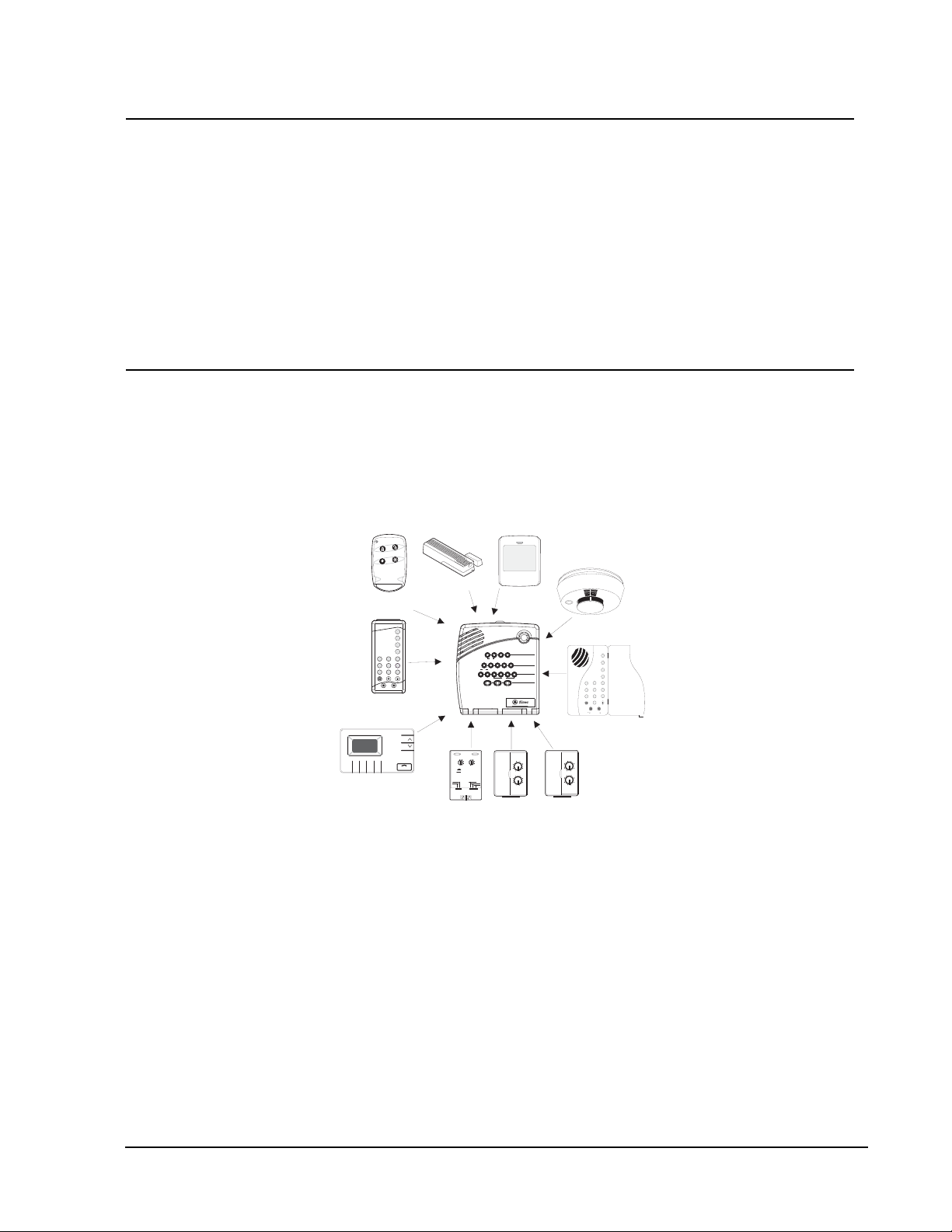
report to the panel and devices that res pond t o co mmand s fr om t he pan el (see Figure 1).
Door/Window
$$"
+, !$
$(,$
# $
.
! "# $% &'($#)*
Sensor
Universal
*
Module
Keychain
*
Touchpad
Remote Handheld
Touchpad
RF Electronic
*
Thermostat
Figure 1. Typical Security System Components
Motion
Sensor
System
Doors &
Motion
Status
Windows
Sensors
H O M E S E C U R I T Y
Arm
Disarm
9 / 05 / 63 / 4 7 / 81 / 2
C O D E
Chim
e
On OffSensorMotion TimeDoors
H O M E C O N T R O L
Lights
Bypass
E M E R G E N C Y
AUX
POLICEFIRE
Test Weekly
Appliance
Lamp
**
Module
Smoke
Sensor
Dialog QS1500 Touchtalk
*
Interactive Keypad
* Not investigated for use by U
Module
Control Panel
The control panel is the main processing unit for all system functions. It receives and
responds to signals from wireless sensors and wireless touchpads throughout the premises. For monitored systems, the panel can be connected to the premises pho ne line for
central monitoring station, pager and/or voice event notification reporting.
Two panel models are available. One has an on-board 2-way voice microphone, the
other does not. The Interrogator
panel.
An optional Braille Kit (60-915) is available for visually impaired users.
4
®
200 Audio Verification Module can be added to either
Simon Secur i t y System
Page 13

Note
ToolBox has not been inve stigated by UL and should not
be used to prog r am panels
in UL lis ted syst e ms.
User Interface
When the panel cover is closed, the panel buttons operate the security system. The
user operates the p anel by pressing panel bu tto ns or by using a touchpad. See t h e U ser
Manual for complete operation instructions.
When the panel cover is open, the buttons program the security system. The panel can
be programmed on-site by the installer or user, or from off-site using ToolBox
®
software. See the “Programming” section of this manual for complete on-site programming instructions. See the ToolBox m a nual and ToolBox on-line help for off-site
programming instructions.
Panel Tamper
If the panel cover is opened while the system is armed, an intrusion alarm occurs.
When the system status button is subsequently pressed, the panel says System Access
Alarm.
System Devices
The system can monitor up to 24 sensors and may use any of the following:
Door/Window Sensor (60-670)
For intrusion protection, install Door/Window sensors on all ground-floor doors and
windows. At a minimum, install them in the following locations:
• All easily accessible exterior doors and windows.
• Interior doors leading into the garage.
• Doors to areas containing valuables such as cabinets and closets.
Indoor Motion Sensor (60-639)
Indoor motion sensors are ideal whenever it is not practical to install door/window
sensors on every opening. Identify areas where an intruder is likely to walk through.
Large areas in an open floor plan, downstairs family rooms, and hallways are typical
locations for indoor motion sensors. For installations with pets, use the SAW Pet
Immune PIR (60-807).
Outdoor Motion Sensor (60-639)
Use outdoor motion sensors to detect motion in a protected outdoor area. Detected
motion in this protected area can sound chimes or turn on outside lights. Do not use
Outdoor Motion Sensors for intrusion protection.
Freeze Sensor* (60-742)
Freeze sensors detect low temperature conditions which may indicate a furnace failure. The sensor contains a bimetallic thermal switch connected to the built-in transmitter. The sensor transmits an alarm signal to the panel when the surrounding
temperature drops to about 41°F (5°C). When the temperature rises to 50°F (10°C),
the sensor transmits a restore signal.
Water Sensor* (60-744)
Water sensors detect a water leak/rising water. The detector is connected to the sensor
by an 8-foot (2.4-meter) cable. Water that reaches both detector contact points activates the sensor, causing it to transmit an alarm signal.
Smoke Sensor (60-848-95)
Smoke sensors provide fire protection by causing an alarm to sound throughout the
house. You can add smoke sensors near sleeping areas and on every floor of the house.
Avoid areas that could have some smoke or exhaust such as attics, kitchens, above
fireplaces, dusty locations, garages, and areas with temperature extremes. In these
areas you may want to install Rate-of-Rise sensors to detect extreme temperature
changes. See “Emergency Planning” and the instructions packaged with the smoke
sensor for complete placement information.
Simon Security System 5
Page 14

Note
The ELM Keychain Touchpad is only compatible with
®
3 panels version 3.3
Simon
and later.
Carbon Monoxide (CO) Alarm* (60-652-95)
The Learn Mode™ CO Alarm alerts users to hazardous levels of carbon mono xide g as.
If dangerous concentrations of gas are present, the red indicator light comes on, the
internal siren goes off, and an alarm is transmitted to the panel. The panel sounds its
own alarm and reports to the central station.
Keychain Touchpad* (60-659)
The Keychain T o uchpad lets you t urn the syst em on and of f from right outside the home
or activate a panic alarm if there is an emergency. If you have X10 Lamp Modules, you
can use keychain touchpads to turn all system controlled lights on and o ff.
ELM (Encrypted Learn Mode) Keychain Touchpad (60-832)
The ELM (Encrypted Learn Mode™) 2-Button Keychain Touchpad is an alkaline battery-powered, wireless touchpad that allows users to arm and disarm their system, and
activate a police or auxiliary panic alarm. Random encrypted signal transmissions provide high security to help prevent signal copying.
Remote Handheld Touchpad (60-671)
The Remote Handheld Touchpad lets you turn the system on and off while in the ho me,
turn system controlled lights on and off (all or individual lights), or activate a panic
alarm if there is a non-medical emergency.
Dialog QS1500 Touchtalk Interactive Keypad* (60-924-01-3)
The wall-mounted wireless Dialog QS1500 Touchtalk Interactive Keypad combines a
conventional Learn Mode
™
touchpad with an RF receiver, speech chip, and voice ampli-
fication circuit.
Dialog RF Electronic Thermostat* (60-909-95)
The Dialog RF Electronic Thermostat provides a money saving and convenient way to
monitor and control temperatures. The thermostat uses low and high temperature limits
to save energy. Temperature limits set on the thermostat determine when the heat or air
conditioning turns on. There can be only one RF Thermostat per system.
Note
Use of X10 modules has not
been investigated by UL.
Water Resistant Personal Help Button* (60-906-95)
The Water Resistant Personal Help Button is a wireless device used for activating
police, medical or auxiliary alarms through your system. When the help button is
pressed, the light mounted under the cover will blink and an alarm signal is transmitted.
X10 Modules*
When the panel is powered using the line carrier power transformer, the system can
work with any of the following modules:
• X10 Lamp Module (13-403)
• X10 Appliance Module (13-402)
• X10 Powerhorn/Remote Siren Module (13-398)
• X10 Universal Module (13-399)
Interrogator 200 Audio Verification Module* (60-787)
The Audio Verification Module (AVM) gives the central station operator the ability to
hear what’s happening at the premises during an alarm and to speak directly to the system user. The operator can then determine how serious an alarm is, find out what kind
of help is needed, and dispatch the appropriate assistance. Only one AVM may be
installed per panel.
Ethernet Interface Module (60-938)
The Ethernet Interface Module is designed to provide an additional reporting method
for Simon panels. The module reports events to the premisesconnect.com web site and
up to two Osborne Hoffman (OH2000E) network receivers.
Premisesconnect.com is used by:
• Installers - to aid in installation and maintenance of security systems.
6
Simon Secur i t y System
Page 15

Note
The DTIM doesn’t support
AVM, remote access or any
call back from the central
station. It is for reporting purposes only.
• Dealers - to simplify customer and account management.
• First Responders - to identify where and how to respond.
• Customers - to receive event notifications and to control their security system.
Dialog™ Telephone Interface Mod ule (DTIM ) (60-879 -95 R)
The DTIM is a battery operated communication link between the security system control panel and the central monitoring station. The DTIM receives radio signals from
the panel, then uses the phone line to report security system events to the central station.
* Not investigated for us e by UL.
Planning
Sensor Types &
Locations
The first step to an easy and successful installation is to decide what areas or items to
protect, which lights or appliances to operate, and the best location for the panel,
touchpad, sensors, and sirens.
Metal objects, mirrors, and metallic wallpaper can block signals sent by the wireless
sensors. Make sure there are no metal objects in the way when installing the system.
Use the planning tables in “Appendix B” to determine the appropriate Sensor Type for
the sensors you will be adding. You’ll need to understand the application for each sensor. For example, Keychain Touchpads are typically programmed as sensor group 01
(Portable panic), used to send an intrusion alarm to a central monitoring station. This
sensor type is instant intrusion, it does not require restoral or supervisory communication with the panel and it is active in 4 arming levels (disarm, arm doors & windows,
arm motion sensors, and arm doors/windows and motions sensors).
Recommended Sensor Groups
Device Recommended Sensor Group
Keychain Touchpad 01, 03, 06, 07
ELM Keychain Touchpad 01, 03, 06, 07
Remote Handheld Touchpad 01, 03, 06, 07
QS1500 Keypad 01, 03, 06, 07
Indoor Motion Sensor 17 (intrusion), 25 (chime)
Outdoor Motion Sensor 25
Smoke Sensor 26
Exterior Door 10
Interior Door 14
Window Sensor 13
CO Alarm 34
Freeze Sensor 29
Water Sensor 38
RF Electronic Thermostat 36
Personal Help Button 01, 03
DTIM 08, 36
Device Locations
Control Panel
Locate the panel where alarm sounds can be heard and is easily accessible for operation.
Do not install the panel near a window or door where it can be reached easily by an
intruder.
Simon Security System 7
Page 16

Note
All Lamp Modules with the
same house code will tu rn
on or flash as a group during
an alarm or when operating
the “Light” button on a Keychain Touchpad.
Remote Handheld Touchpad
Locate Remote Handheld Touchpads where they will be convenient and offer quick
access to the user.
QS1500 Keypad
Locate QS1500 Keypads where they will be convenient and offer quick access to the
user. When mounted, they must be within 600 feet (183 meters) of the control panel.
Keychain Touchpad
Keychain Touchpads attach to the owner’s key ring or can be conveniently carried.
Dialog Telephone Interface Module
Mount the DTIM within 100 feet (30 meters) of the panel, but no closer than 10 feet (3
meters) to another DTIM or the panel.
X10 Modules
The system can control up to 8 individual unit numbers on Lamp, Wall switch, Appliance, and Universal Modules.
House Code and Unit Numbers
Each device (lamp, appliance, etc.) controlled by the panel must have an identification
setting. The modules use two dials to set identification codes: one with letters A through
P and one with numbers 1 through 16.
The lettered dial sets the house code, which enables the system to differentiate this
home from other homes in the area. Set all modules (except the remote siren) and the
panel to the same house code.
The numbered dial sets the un i t number, which identifies and lets you control a specific
device. Each device must have a unique unit number (1- 8) to be individual ly controlled.
For example, lights and appliances operated from a Remote Handheld Touchpad or
operated by a sensor; or lights programmed to go on duri ng the entry/exit delay or at
scheduled times.
Note
When unit numbers 9-16 are used for lamp modul es, they can only be controlled by an al l on
or all off command. A lamp will flash to the arming level if its unit number is set to 10. A lamp
set to unit number 10 will flash once if the panel is disarmed, twice if doors & windows are
armed, etc. The remote si re n can be set to any unit number to hear alarm sounds. Set it to
unit number 9 to also hear arming level beeps, status beeps, and trouble beeps. Do not use a
lamp module to contro l appl i ances. Use an appliance m od ul e, si nce the wattage rating on
Lamp Modules is less th an on Appliance Modules .
Note
The house code instructions
that come with the Powerhorn Siren won’t work with
this panel. Follow the housecode instructions given here.
Note
If you are using a Universal
Module to operate a device ,
make sure to assign a
unique unit number to this
module, choosing from 1- 8.
8
Manually Controlling Lights
Lights with even unit numbers (2, 4, 6, 8) can be controlled from either the panel,
Remote Handheld Touchpad or QS1500 Keypad. Lights with odd unit numbers (1 , 3, 5,
7) can only be controlled from a Remote Handheld Touchpad or QS1500 Keypad.
¾
To Fill Out the Home Control Planning Table:
1. Set the house code on all modules (except the remote siren) to the same letter.
2. Set the Remote Siren house code to the next alphabetical letter. For example, if you
chose house code B in step 1 above, set the remote siren house code to C.
3. Set the module unit numbers.
4. List the location of the lamp or appliance in the Location column of the Home Control Planning Table.
5. Write the location of each Lamp Module on an adhesive note and label the module.
6. Decide if the device should be activated by sensors, entry/exit delay, time, or a
combination. An example of sensor activation is using a motion sensor to turn on a
light. Record the information in the appropriate columns.
Simon Secur i t y System
Page 17

Use the following tables to help you further plan X10 module installation.
X10 House Code Assignments
X10 Device Settings
Lamp, Appliance, Universal Set all modules to the same house code (A
Remote Siren House code must be set to the next higher
- O) except the remote sirens.
alphabetical letter.
X10 Unit Number Assignments
Unit # Result
1 - 8
• Used for sensor-activated, time-activated, and entry/exit delay lights.
• Sensor activated lights are enabled and disabled by pressing the
LIGHTS Sensor Activated button on the panel.
• Time activated lights are enabled and disabled by pressing the
LIGHTS Time Activated button on the panel.
• If using the universal module to operate a device, be sure to assign a
unique unit number.
• The STAR button on the KeyChain Touchpad activates the universal
module controlled device or to turn on special lights if programmed.
9
• Used for remote siren or light control.
• For remote siren use, sirens with this setting sound alarms, arming
level beeps, status beeps, and trouble beeps.
• For light control, lamp modules with this setting are controlled by an
all on or all off command.
Installing the
System
Note
If Option 40 Trouble Beeps
is on, the panel will sound
six trouble beeps every
minute the panel cover is
open.
10
• Used for remote siren or light control.
• For remote siren use, sirens with this setting only sound alarms.
• For light control, lamps will flash according to selected arming level
and are controlled by an all on or all off command.
11 16
• Used for lamp modules and controlled by an all on or all off command.
This section describes how to open the panel for mounting, mount the panel, connect
sirens, hardwire contacts, and the AC power transformer.
Materials Needed
• Pencil
• Phillips Screwdriver
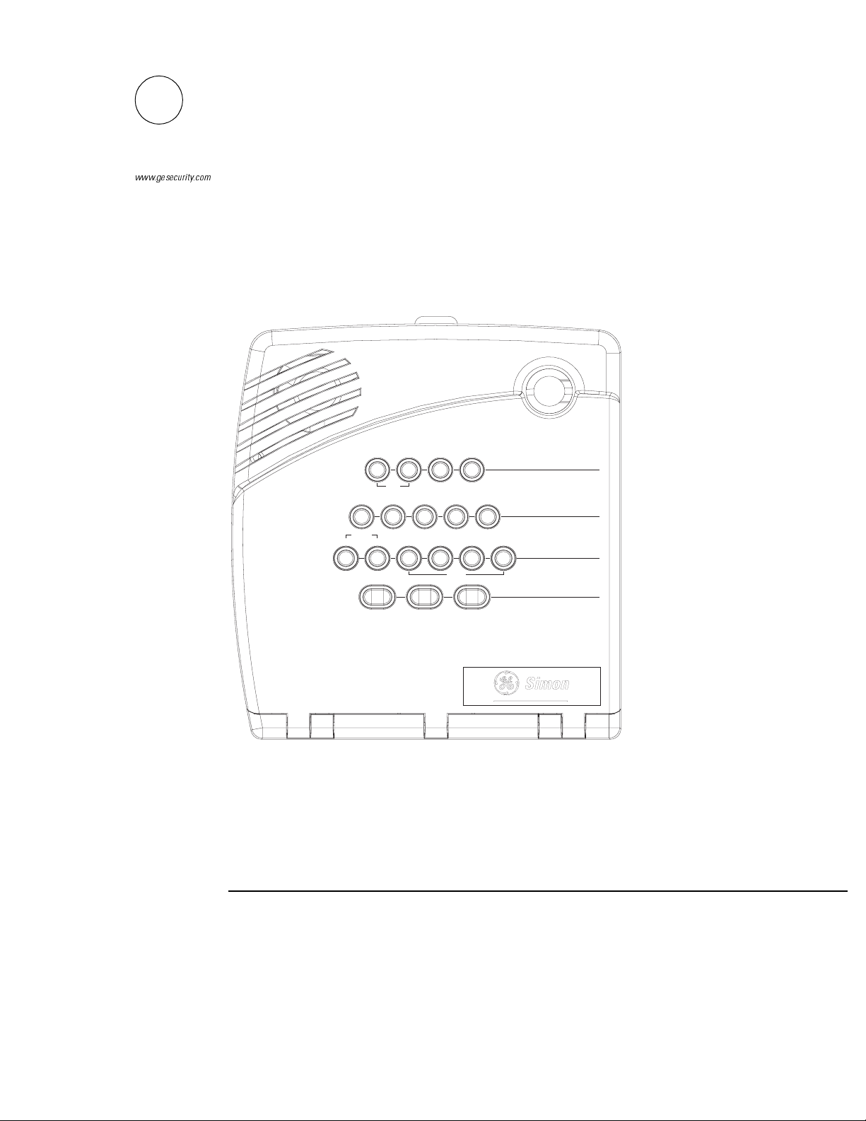
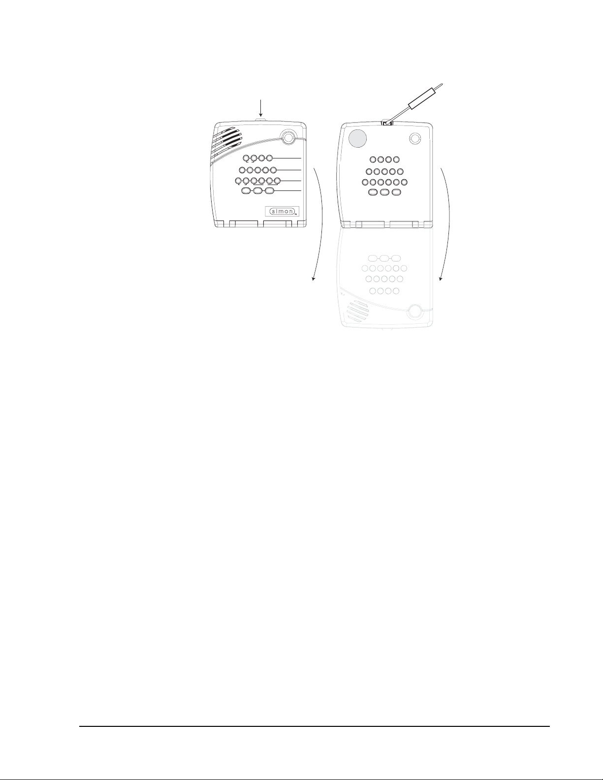
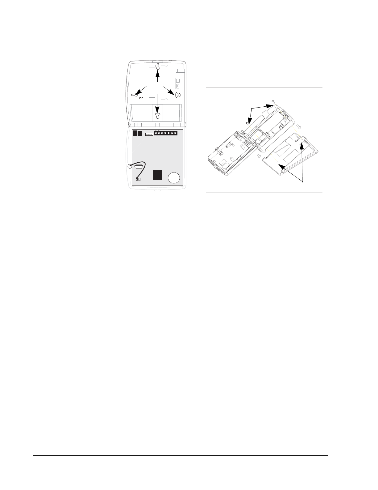
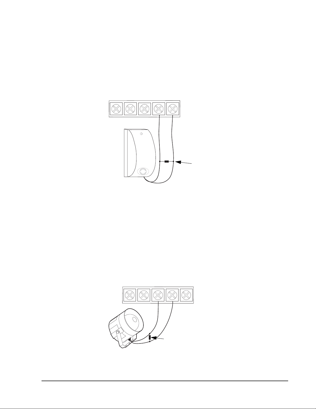
Opening the Panel Cover and Chassis
Tabs at the top of the panel secure and release the front cover and the chassis. The
plastic hinges on the panel bottom allow the cover and chassis to swing down and out
of the way (see Figure 2).
Simon Security System 9
Page 18
Press tab with thumb,
Press tab up with
then swing cover down.
screwdriver, then
swing chassis
down.
D o o r s &
M o t i o n
W i n d o w s
S e n s o rs
S t a t u s
H O M E S E C U R I T Y
D is a r m
S y s t e m
9 / 0
5 / 6
S e n s o r
L i g h t s
A U X
O n O f f
C O D E
H O M E C O N T R O L
E M E R G E N C Y
D o o r s
1 / 2
S p e c i a l
M o t i o n T im e
C h i m e
F I R E P O L I C E
A r m
3 / 4 7 / 8
T e s t W e e k l y
Figure 2. Opening the Panel Cover and Chassis
Mounting the Panel
The panel must be securely mounted on a wall or on the optional Tabletop Base.
Note
When choosing the AC ou tlet location for the AC power
transformer, make sure the
outlet is not controlled by a
switch or that it is not part of
a ground fault interrupt cir cuit (GFIC).
Note
A tabletop mounted application is only recommended
when the panel requires the
power and telephone ca bl e
as the only hardwire connections. Use the wall mounted
position in all other applications.
Wall Mounted Panel
The panel must be securely mounted to the wall using the 4 screws supplied to prevent
accidental movement and to protect the consumer from the system wiring and terminals.
1. Choose a panel location.
2. Run all necessary power, phone, siren, and hardwire contact wires to the desired
panel location.
3. Refer to Figure 3 (Wall Mount) for mounting hole locations.
4. Hold the panel against the wall and mark the mounting hole locations with a pencil.
5. Insert wall anchors into holes where studs are not present.
6. Install all screws and tighten gently.
Tabletop Mounted Panel
The tabletop base must be fitted to the back of the panel if the panel is to be used on a
table or bench.
1. Select a suitable location near power and phone line.
2. Run all necessary wires from the panel through the openings in the tabletop base.
3. Refer to Figure 3 (Tabletop Mount) for mounting hole locations.
4. Place the panel back on the tabletop base until the top and bottom panel mounting
holes line up with the mounting holes on the tabletop base.
5. Secure the panel to the tabletop base with the screws provided.
6. Ensure the cables are neat and will not create a tripping hazard.
10
Simon Secur i t y System
Page 19
Wall Mount
Mounting
Holes
Tabletop Mount
Mounting
Screws
Tabletop Mounting
Holes
Figure 3. Panel Mounting Hole Locations
Connecting Hardwire Devices
The panel has 5 screw terminals located on the upper-right corner of the circuit board
(see Figure 3) for connecting AC power, sirens and/or hardwire detectors.
Note
All inputs and outputs are
Class II power limited circuits.
Note
The total current available
from the DCOUT terminal is
250 mA (50 mA with the
Ethernet Interface Modu le
installed) at up to 122° F
(50° C).
AC Terminals
These terminals are used for connecting a Class II 9 VAC, 700 mA AC power transformer. For systems with no X10 modules, use transformer part no. 22-109-ITI. For
systems with X10 modules, use transformer part no. 22-129-ITI.
HWIN1, HWIN2, and DCOUT Terminals
These terminals are dual purpose and can be used for either siren or hardwire detector
connections. Options 96 and 97 control how the output on HWIN1 and HWIN2 will
function.
Sirens
From the factory, these terminals are set up for siren operation with HWIN1 handling
interior sirens (status and alarm sounds), HWIN2 handling exterior sirens (alarm
sounds only), and DCOUT providing the positive (+) voltage.
With Option 53: Hardwire Siren Supervision turned on, sirens connected to HWIN1
and HWIN2 are supervised and require a 4.7k resistor in the circuit. If either of these
terminals i s not used with Option 53 on, you must connect a 4.7k resistor between the
unused terminal and DCOUT.
Hardwire Detectors
To set up HWIN1 and/or HWIN2 for hardwire detectors, make the required connections as described under “Wiring Hardwire Contacts,” then proceed to the “Programming” section to add (learn) them into panel memory.
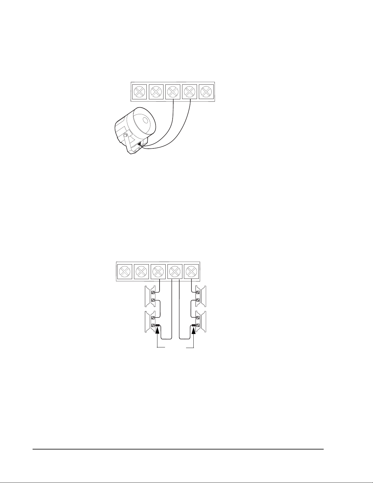
Wiring Interior Sirens
Panel terminal HWIN1 can be used for connecting interior sirens and activates for status and alarm sounds.
Simon Security System 11
Page 20
Note
n)
)
Do not install the resistor at
the panel terminals. This
does not provide supervision
of the wire.
Note
If you are installing only an
interior siren and no exterior
siren and Option 53 is on,
you must connect a 4.7k
resistor between the HWIN2
and DCOUT terminals in
addition to the resistor
between HWIN1 and
DCOUT shown in F igur e 4.
For circuit supervision, which allows the panel to detect if the siren wire is cut (open) ,
Option 53: Hardwire Siren Supervision must be turned on (see the “Programming ” section) and interior sirens must be wired with a resistor in the circuit.
LD105 Hardwire Interior Siren
Connect the LD105 Hardwire Interior Siren (13-374) to the panel using a 4.7k resistor
(included with siren) as shown in Figure 4. The resistor must be connected across the
siren wires as close to the siren as possible.
A C A C
Figure 4. Hardwire Interior Siren with Supervision
H W I N 2
Red
H W I N 1D C O U T
Black
4.7k Resistor
(located at sire
Note
Do not install the resistor at
the panel terminals. This
does not provide supervision
of the wire.
Note
If you are installing only an
exterior siren and no interior
siren and Option 53 is on,
you must connect a 4.7k
resistor between the HWIN1
and DCOUT terminals in
addition to the resistor
between HWIN2 and
DCOUT shown in F igur e 5.
Wiring Exterior Sirens
Panel terminal HWIN2 can be used for connecting exterior sirens and activates when
intrusion and fire alarms occur.
Exterior sirens can be wired with or without a resistor in the circuit for supervision. For
circuit supervision which allows the panel to detect if the siren wire is cut (open),
Option 53: Hardwire Siren Supervision must be turned on (see the “Programming ” section).
Hardwire Exterior Siren with Supervision
Connect the Hardwire Exterior Siren (13-046) to the panel using a 4.7k resistor
(included with siren) as shown in Figure 5. The resistor must be connected across the
siren wires as close to the siren as possible.
A C A C
H W I N 2
Black
4.7k Resistor
(located at siren
H W I N 1D C O U T
Red
12
Figure 5. Hardwire Exterior Siren with Supervision
Simon Secur i t y System
Page 21
Hardwire Exterior Siren without Supervision
With Option 53 turned off, connect the Hardwire Exterior Siren (13-046) to the panel
without a resistor as shown in Figure 6
Important !
Connect only normally
closed (N/C) reed switc hes
to HWIN1 and/or HWIN2.
Other types of hardwire
detectors should not be
used.
Note
Do not install the resistor at
the panel terminals. This
does not provide supervision
of the wire.
A C A C
Figure 6. Hardwire Exterior Siren without Supervision
H W I N 2
Black
H W I N 1D C O U T
Red
Wiring Hardwire Contacts
Y o u can conne ct hardwi re reed swi tches (normall y closed loop onl y) to HWIN1 an d/or
HWIN2, if either terminal is not being utilized for a hardwire siren.
The total resistance of the wire loop must not exceed 3 ohms. This allows you to use
up to 200 feet (61 meters) of 2-conductor, 22-gauge stranded wire.
Connect hardwire reed switch es to the p anel us ing a 47k r esis tor as sh own in F igur e 7.
The resistor must be connected at the last switch in the circuit.
A C A C
Figure 7. Connecting Normally Closed Hardwire Reed Switches
H W I N 2
Resistor
H W I N 1D C O U T
47k
Wiring a Phone Line to the Panel
You can connect a phone line to the panel for systems monitored by a central monitoring station and/or systems that notify users by a digital pager or voice event notification.
Basically, there are two methods for connecting the panel to a phone line; full line seizure and no line seizure.
Simon Security System 13
Page 22
Note
Black
F
For UL Listed systems, the
RJ-31X jack must be
mounted within 5 feet (1.5
meters) of the panel.
Full Line Seizure
This method requires that the panel be wired ahead (or in front) of all other phones,
answering machines, computers, or other devices on the phone line. This allows the
panel to take over (seize) the phone line, even if another device on the line is in use.
An RJ-31X (CA-38A) jack should be installed when wiring for full line seizure. This
lets the user quickly and easily disconnect the panel from the phone line in case the
panel disables the phone line due to a malfunction.
Full Line Seizure Wiring with an RJ-31X
1. Run a 4-conductor cable from the TELCO block to the RJ-31X (A in Figure 8).
2. Connect the 4-conductor cable wires to the RJ-31X (B in Figure 8).
3. Disconnect the Green and Red premises phone jack wires from the TELCO block
and splice them to the 4-conductor cable Black and White (or Yellow) wir es (C in
Figure 8). Use weatherproof wire connectors for these splices.
4. Connect the 4-conductor cable Green and Red wires to the TELCO block TIP (+)
and Red to RING (-) posts (D in Figure 8).
5. Connect the phone cord included with the panel to the RJ-31X and the panel LINE
IN jack (E in Figure 8)
E
H W I N 1
H W I N 2
BRN GRY
GRN RED
Green
TIP
(+)
D
Green
Black
C
Green
igure 8. Full Line Seizure Wiring with an
RJ-31X
B
Red
White
(or Yellow)
RING
(-)
Red
White (or Yellow)
Red
A
Premises
Phone Jack
Wires
Lone Premises Phone
Premises
Phone Jack
Figure 9. Full Line Seizure Wiring with 1
A
B
Premises Phone
H W IN 1
H W IN 2
Full Line Seizure Wiring with 1 Premises Phone
Note
If the customer ever add s a
phone or other phone device
to another phone jack, full
line seizure no longer exists.
Inform the customer to contact you if they want to add a
phone or other device so
that you can rewire for full
If a single phone is all that exists on the premises, full line seizure can be acco mplis hed
without an RJ-31X.
1. Disconnect the phone from the premises phone jack and plug it into the panel
PHONE jack (A in Figure 9). This jack is disconnected automatically whenever the
panel reports.
2. Connect the phone cord included with the panel to the panel LINE IN jack and the
premises phone jack (B in Figure 9).
line seizure by adding an
RJ-31X.
14
Simon Secur i t y System
Page 23
Note
A
B
d
C
Connecting the panel to a
standard phone (voice) lin e
in this manner should be
avoided. Other device s i n
use at the same time the
panel is using the line can
prevent reports from going
through.
Note
Do not plug in the transformer at this time
No Line Seizure
This method is typically used where DSL (digital subscriber line) service exists. DSL
allows multiple devices on a single phone line to be used simultaneously. Simply connecting the panel LINE IN jack to an available phone jack on the premises is all that is
required.
An in-line filter may be required to ensure panel reporting is successful.
* For UL installations, installer needs to verify line seizure.
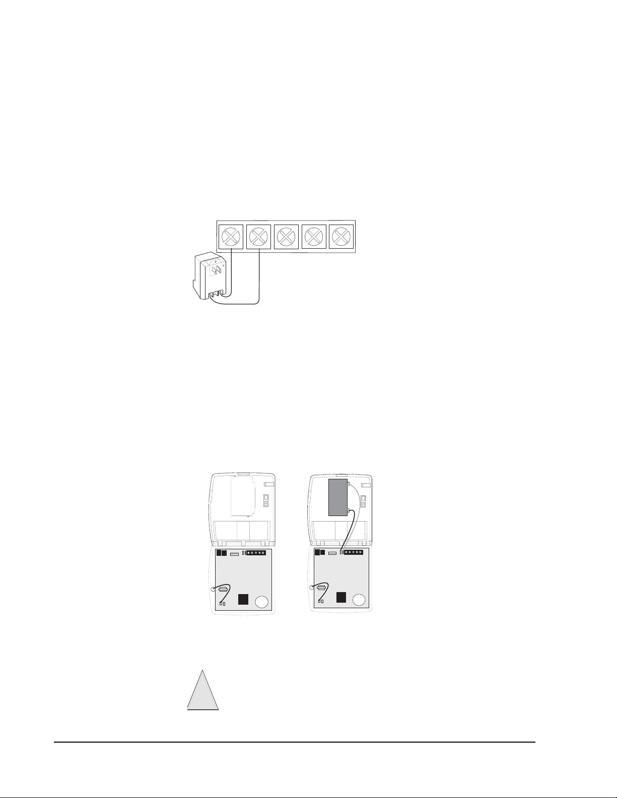
Wiring the Power Transformer
Connect the power transformer to the panel AC terminals as shown in Figure 10.
A C A C
Figure 10. Connecting the Power Transformer
H W I N 2
H W I N 1D C O U T
Powering Up the Panel
When applying power to the panel connect the battery first, then plug in the AC power
transformer . This sequence prevents a battery fault condition.
Installing the Panel Backup Battery
1. Remove the cover from the Battery Compartment (A in Figure 11).
2. Connect the red and black battery leads (included with panel) to the battery and
panel terminals (see B in Figure 11).
3. Place the battery in the compartment, running the wires through the openings in
the top and bottom of the compartment.
+
Black
-
+
Red
-
Cover
-
+
Figure 11. Installing the Panel Backup Battery
4. Replace the cover to the Battery Compartment (see Figure 12).
Tighten the screws to the Battery Compartment securely. Failure to do so coul
result in damage to the panel board when the cover and chassi s are closed.
!
aution
Simon Security System 15
Page 24
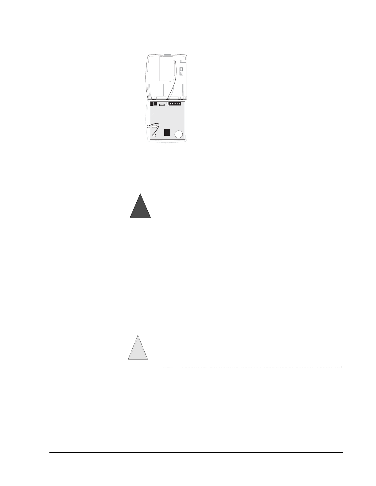
Note
Make sure the outlet is not
controlled by a switch or that
it is no t p a rt of a gr ou nd f aul t
interrupt circuit (GFIC).
Red
+
Black
-
-
+
Figure 12.Battery Connected in Compartment
Applying AC Power
1. Remove the center screw from the outlet cover plate and hold the cover plate in
place.
Use extreme caution when securing the transformer to a metal outlet cover.
You could receive a serious shock if a metal outlet cover drops down onto the
prongs of the plug while you are securing the transformer and outlet cover to
!
Warning
2. Plug the transformer into the lower receptacle of the outlet so that the hole in the
3. Insert the cover plate screw through the transformer tab and the outlet cover plate.
the outlet box.
transformer tab lines up with the outlet cover screw hole. The panel voice should
announce “Hello, system XX is OK”
Tighten the screw firmly.
Note
See “Light and Appliance
Controls” to program a Keychain Touchpad to activate a
Universal Module controlled
device.
Installing X10 Modules
Lamp and Appliance Modules
1. Set the unit code dial to a unit number different from all other X10 modules
(between 1 and 8).
2. Set the house code for the installation.
3. Plug the module into a wall outlet.
4. Plug the lamp/appliance into the module.
Do not plug in appliances or lamps with 300-watt or larger bulbs into Lamp
Modules
!
Caution
Universal Module
1. Set the unit code dial to a unit number different from all other X10 modules
(between 1 and 8).
2. Set the house code for the installation.
3. Set the module switches to momentary and relay only.
4. Connect the module terminals to the desired device terminals.
5. Plug the universal module into a wall outlet.
16
Simon Secur i t y System
Page 25

Sensor Installation
e
Program sensors and devices b efore you i nstall them. Use the fol lowing sectio n to pro gram the panel and add the sensors to panel memory.
Programming Entering Program Mode
There are 2 codes you can use to enter program mode.
Utility Access Code 1 (Dealer Code)
Depending upon how Option 54 is set, the default utility access code is 654321,
54321, 4321 (factory default), or 321. This code can be used for all programming.
Utility Access Code 2 (Installer Code)
Depending upon how Option 54 is set, the default access code is 654321, 54321, 4321
(factory default), or 321. This code is limited to changing all but the following: Utility
Access Code 1, Options 4, 5, 6, 8, 9, 12, 13, 54, and 69.
1. Open the panel cover.
2. Enter Utility Access Code 1 or 2 using the numbered keys.
Note
Do not remove panel power
while in program mode. Programming changes are
saved only when exiting program mode (closing the
panel cover).
The panel is now in program mode. Follow the programming arrows on the panel
label. The system prompts you through programming steps with beeps and voice messages.
¾
Program the panel in this order:
1. Set the panel clock.
2. Add (learn) sensors.
3. Set House Code and Light & Appliance Controls (Entry/Exit activated lights,
Sensor activated lights, Time activated lights).
4. Change numbered Options as needed.
Note
If Option 8: Phone Lock is
on, options 04, 05, 06, 07,
08, 09, 12, 13, 54, 56 and
Dealer Code will not reset to
their defaults.
Exiting Program Mode
Close the cover to exit program mode when you are finished programming.
Do not power down the p anel whil e in p rog ram m ode or all p rog ramm ing will b
lost. The panel stores programmed information only when you exit program
!
mode (close the cover and leave cl osed for at least 5 seconds).
Caution
Reset Memory to the Factory Defaults
1. Open the panel cover and enter Utility Access code 1.
2. Unplug the transformer and disconnect the battery.
3. Simultaneously press and hold Cancel, Clock Set, and Minutes +.
4. Restore power to the panel with the battery while pressing these three buttons.
The panel announces “Hello. System XX OK.” Release the buttons.
5. Plug in the transformer to the outlet.
Set the Clock
1. Press Clock Set from the Start Menu.
2. Press the Hours + and
voice announces the correct hour.
3. Press the Minutes + and
panel announces the correct minutes.
4. Press Done. The panel announces the set time.
– keys and listen to the voice prompts. Stop when panel
– keys and listen to the voice prompts. Stop when the
Simon Security System 17
Page 26
Adding (Learning) Sensors
These instructions describe how to add sensors, touchpads and other system devices
into panel memory. The panel recognizes a sensor when you press a sensor program
button, press and release a tamper switc h, press a sensor test butto n, or put a sensor in to
alarm.
Note
The hardwire inputs m ust have sire ns or hardwire sensors with 47k Ohm resistors connected
between the DCOUT an d H W IN1 or HWIN2 terminals b ef or e learning in a sensor. If one of
these connections is not made, the panel will learn in a hardwire zone.
Note
If you are installing a sensor on a gun case, jewelry box, or sim i l ar u sage, and the sensor is
active in level one, you must sub-disarm to avoid putting the panel into alarm when the sensor
and the magnet are separated.
The following table, “Device Programming,” describes the programming button location for each device.
Device Programming
Device To Program
Door/Window Sensor Press button on top of sensor (cover removed)
or trip tamper
Motion Sensor Pre ss button on ba ck of senso r (moun ting p late
removed) or trip tamper
Smoke Sensor Trip tamp er, press test button, remove from
base or put sensor in alarm
Keychain Touchpad Press and hold Lock & Unlock buttons together
ELM Keychain Touchpad
Press
Press
Hold Flash Flash Flash
Press
Hold until LED is done flashing.
Hold
Hold
Flash
Flash
Flash
Remote Handheld Touchpad Press the EMERGENCY buttons
QS1500 Keypad Press Lights Off button 6 times
Hardwire Sensors Separate sensor from magnet
CO Alarm Plug in the module wait 5-7 seconds press and
hold the test button for 9 beeps
Freeze & Water Trip tamper or press and hold button on top of
the sensor (cover removed) until control panel
confirms programming. If button is not held
down long enough, SYSTEM STATUS reports
sensor as open.
18
Dialog RF Electronic Thermostat Unplug the thermost at from the ba se plate, w ait
a few seconds, then plug the thermostat back
into the base plate.
Personal Help Button Press the help button until the light blinks.
Simon Secur i t y System
Page 27

Device Programming
Device To Program
Note
For a more specific location
name, press Option # for
compass directions (north,
northeast, east, southeast,
south, southwest, west,
northwest).
DTIM
Note
When changes are made to pane l
programming option s th at af fe ct
DTIM (i.e. phone numbers), the
DTIM is not updated until panel
programming mode is exited. After
a few minutes, the DTIM sh ould
be updated.
Press and release the DTIM tamper switch as
follows:
1. Press 3 times, holding the tamper switch
down on the third press until the LED
flashes 3 times. Release after third flash.
2. Immediately press 2 times, holding the
tamper switch do wn on the second press
until the LED flashe s 2 times. Rel ease afte r
second flash.
3. Immediately press and hold, then wait for
the panel to bee p once in dicating it learned
the DTIM. Release the tamper switch.
When adding (learning) sensors, the panel uses an ascending numbering sequence
starting with 1. You can override this by entering a 2 digit sensor number using the
numbered keys immediately after entering the sensor group.
Use the T a ble in Ap pendix B, wh ich wa s filled out d uring the s ystem plann ing, to h elp
program sensors.
To add a hardwire or RF sensor or remote control:
¾
1. Press Add. The panel announces “Select from Main Menu.”
2. Press Sensor/Remote. The panel announces “Press button on sensor.”
3. Press the sensor program button or release sensor tamper switch. The panel
announces “Keychain Remote. Press sensor again for next name o r pres s Done to
select.”
4. Press Sensor/Remote repeatedly until you hear the name or item you want to use.
An alphabetical list of names the panel uses appears in Appendix B. Each name
may be used more than once.
5. Press DONE when you hear the desired name. The panel announces “Use numbered keys to enter sensor group.”
6. Enter the 2-digit sen sor gr oup. The p anel announ ces th e sensor group an d the fir st
available sensor number, then prompts you to press DONE to accept.
7. Press DONE. The panel confirms programming by announcing the sensor number, name, and group.
Simon Security System 19
Page 28

Version 3
Press for program
*
information.
Light
Control
Unit #
Instruction
Summary
Add Option
Option #1:
Panel Beeps
Panel Voice
Option #2:
Latchkey Time
Option #3:
Option #36:
Sensor Activated Light Lockout Start Time
Sensor Activated Light Lockout Stop Time
Option #37:
Chime Voice
Option #41:
Speaker Volume
Option #42:
Pager Phone Number
Option #43:
Status Beep Volume
Option #55:
Add Option #
Press
and follow voice prompts.
See Note
Entry/Exit
Delay
*
DONE
START MENU
Add
Option #
**
Delete
CONTROL MENU
Sensors
Cancel
MAIN MENU
Sensor/
Remote
*
**
645
-
Add Access Code
Add
Press
use red numbers to enter 4-digit code.
Set Clock
Clock Set
Press
Access Clock
Code
10
Time
Minutes
Access Code
See Note
Hours
Test
-
+
DONE
Minutes
See Note
Set
Hours
, then
DONE
System should be checked
by a qualified technician
at least every three years.
32
Note:
Hold key or press
+
repeatedly until you
hear the desired item.
978
Delete
To delete an option or access code
Delete
press
and follow the voice
prompting.
Cancel
If you make a mistake or want to
start over press
Cancel
Sensor or Phone Test
To select a test, press
follow the voice prompting.
422-2806 Rev A
Test
and
¾To delete sensors:
1. Press Delete. The panel announces “Select from Main Menu.”
2. Press Sensor/Remote repeatedly until you hear the name and number you want
deleted, the n press DONE. The panel announces that the sensor is deleted.
Note
A Keychain Touchpad button
can also be programme d t o
control a light or appliance
module.
X10 Module Operation
Use the following procedure to program X10 module operations into panel memory.
Notice that the Light Control button is used to program all X10 module operations
(light, appliance, and universal).
¾
To program the house code:
1. Press Add.
2. Press Light Control repeatedly until you hear the desired house code letter.
3. Press DONE.
4. Set the HOUSE dial on each lamp, appliance, and universal module, to the same
letter.
5. Set the HOUSE dial on powerhorn/remote sirens to the next sequential alphabetical
letter.
¾
To add an entry/exit activated module:
1. Press ADD.
2. Press Light Control.
3. Press Unit # repeatedly until you hear the unit number that matches the one you
chose for the module.
4. Press Entry/Exit Delay. The panel confirms your programming.
¾
To add a sensor-activated module:
1. Press ADD.
2. Press Light Control.
3. Press Unit # repeatedly until you hear the unit number that matches the one you
chose for the module.
4. Press Sensors until you hear the sensor you want to control the light.
20
Simon Secur i t y System
Page 29

5. Press DONE. The panel confirms your programming.
p,
st.
¾
To add a time-activated module:
1. Press Add.
2. Press Light Control.
3. Press Unit # until you hear the unit number that matches the one you chose on the
module.
4. Press Time.
5. Press Hours and Minutes to set the beginning of the schedule.
6. Press DONE.
7. Press Hours and Minutes to set the end of th e schedule.
8. Press DONE. The panel confirms your programming.
¾
To delete an Entry/Exit-activated module:
1. Press Delete.
2. Press Light Control.
3. Press Unit # repeatedly until you hear the unit number you want deleted.
4. Press Entry/Exit Delay, then press DONE. The panel confirms your program-
ming.
To delete a sensor-activated module:
¾
1. Press Delete.
2. Press Light Control.
3. Press Unit # repeatedly until you hear the unit number you want deleted.
4. Press Sensors until you hear the one you want deleted.
5. Press DONE. The panel confirms your programming.
Note
Devices between the Ethernet Interface module and the
transmission line (hub,
router, cable modem, etc.
must be UL listed and mu st
not receive power from a
switched outlet.
¾
To delete a time-activated module:
1. Press Delete.
2. Press Light Control.
3. Press Unit # repeatedly until you hear the unit number you want deleted.
4. Press Time.
5. Press DONE. The panel confirms your programming
Ethernet Interface Module
Requirements
• Broadband Internet connection (DSL or cable modem)
• An available 10-Base-T or 10/100-Base-T Ethernet Port
If connecting devices (“hub”, router, cable modem) do not have battery backu
!
Caution
Activate the Ethernet Interface Module
In order to program the module through the Simon panel you must activate the connection between the panel and module. Activating the communication channel and
gaining access to the module’ s Remote Options is accomplished by turnin g Option 89
On. Follow the instructions below to activate the module.
¾
1. Enter Utility Access Code 1 (Dealer Code) if you are not already in program
2. Press Add.
the system will lose communication with the reportin g sta tion if AC power is lo
To activate the Ethernet Interface module:
mode.
Simon Security System 21
Page 30

Note
Although the panel voice
prompts you through programming, it is not nece ssary to wait for the complete
message before pressi ng
the next button in the programming sequence.
3. Press Option #.
4. Press 8, then 9.
5. Press Done. The panel announces “Option 89 is on.”
6. Verify both t he red and green LEDs on the module and ethernet connector are
blinking.
See Options 89-92 in this manual for custom programming options. See the Ethernet
Interface Installation Instructions (466-2161) for more information on this module.
Numbered Options
Numbered options let you customize system operation according to dealer and user
needs.
The “Option Settings” table in Appendix B lists all system options and their characteristics. Fill in the last column of the table before programming to help speed up the programming process.
There are two ways to reach the desired option setting.
•Press Add or Delete, then press Option # repeatedly until you hear the option you
want changed.
Or—
•Press Add or Delete, Option #, then enter the option number using the numbered
keys.
The following instructions use the last method.
Option 01: Panel Piezo Beeps
Determines whether the panel piezo produces beeps based on system activity (on) or is silent (off). The following table describes all
possible beeps.
Note
For all UL listed systems, Op tio n 1 m ust be on (added).
Panel Piezo Beeps
Activity Piezo Beep Response
ARM Doors & Windows Exit Delay—2 beeps sound every 5 seconds and 2
times per second during the last 10 seconds.
Silent Exit—2 beeps sound at the beginning of the
exit delay and 2 more sound just before the exit
delay expires.
Entry Delay—2 beep s sou nd every 5 seco nds and 2
times per second during the last 10 seconds.
(Default = on)
¾ To turn on Panel Piezo Beeps, press:
1. Add
2. Option #
3. 01
4. DONE
¾
To turn off Panel Piezo Beeps, press:
1. Delete
2. Option #
3. 01
4. DONE
22
Simon Secur i t y System
Page 31

Panel Piezo Beeps
Activity Piezo Beep Response
Option 02: Panel Voice
ARM Motion Sensors Exit Delay—3 beeps sound every 5 seconds and 3
ARM Doors/Windows &
Motion Sensors
DISARM 1 beep
CHIME DOORS 2 beeps (when programmed)
CHIME SPECIAL MOTION 3 beeps (when programmed)
Trouble Beeps 6 beeps every minute. Press SYSTEM STATUS to
No Activity 20 beeps every minute for 5 minutes (when pro-
times per second during the last 10 seconds.
Silent Exit—3 beeps sound at the beginning of the
exit delay and 3 more sound just before the exit
delay expires.
Entry Delay—3 beep s sou nd every 5 seco nds and 3
times per second during the last 10 seconds.
Exit Delay—4 beeps sound every 5 seconds and 4
times per second during the last 10 seconds.
Silent Exit—4 beeps sound at the beginning of the
exit delay and 4 more sound just before the exit
delay expires.
Entry Delay—4 beep s sou nd every 5 seco nds and 4
times per second during the last 10 seconds.
stop beeps for 4 hours.
grammed)
(Default = on)
Determines whether the panel announces all status, alarm, and program mode messages (on), or only announces messages for canceled alarms, open sensors (protesting), when SYSTEM STATUS is
pressed, or if the panel is in program mode (off).
¾
To turn on Panel Voice, press:
1. Add
2. Option #
3. 02
4. DONE
¾
To turn off Panel Voice Beeps, press:
1. Delete
2. Option #
3. 02
4. DONE
Simon Security System 23
Page 32

Option 03: Latchkey
(Default = off)
Determines whether the panel reports a Latchkey alarm if the system is not disarmed at a preset time between midnight and 11:59
P.M. (on). If the Latchkey feature is disabled (off), the panel will not
report a Latchkey alarm.
Note
The system clock must be set for the Latchkey featur e t o w or k.
Option 04: Primary Phone Number
Lets you program up to a 26-digit central monitoring station
receiver phone number for monitored systems (on), or delete
an existing primary phone number (off).
•Press Test for each required pause
•Press Add for a *
•Press Delete for a #
Each pause, * and # uses one of the 26 available places.
Note
Pressing DONE is requi re d if yo u enter fewer than 26 digits. The
phone number is autom at i ca lly stored without pressing D O NE if
all 26 places are used.
¾ To set Primary Phone Number, press:
1. Add
2. Option #
3. 04
4. Use the numbered keys to enter the phone num-
5. DONE
¾
1. Delete
2. Option #
3. 04
4. DONE
¾ To turn set Latchkey, press:
1. Add
2. Option #
3. 03
4. Press the Hours +/- buttons to select the
correct hour.
5. Press the Minutes +/- buttons to select the
correct minute.
6. DONE
¾
To turn off Latchkey, press:
1. Delete
2. Option #
3. 03
4. DONE
(Default = off)
ber (up to 26 digits).
To delete Primary Phone Number, press:
24
Simon Secur i t y System
Page 33

Option 05: Secondary Phone Number
(Default = off)
Lets you program up to a 26-digit central monitoring station
receiver/numeric pager/voice event notification phone number for monitored systems (on), or delete an existing secondary phone number (off).
•Press Test for each required pause
•Press Add for a *
•Press Delete for a #
Each pause, * and # uses one of the 26 available places.
Note
For numeric pagers, add 2 pauses at the end of the number.
Some pagers may require 3, 4 or more additional pauses to work
correctly. Pagers that require the panel to dial more than 26 digits
will not work. The panel calls a numeric pager twice for each
report. Silent alarms report to a pager as an intrusion alarm. See
the Table “Pager Reporting Messages” for more r eporting information.
Pressing DONE is required if you enter fewer than 26 digi ts. The
phone number is autom atically stored withou t pressing DONE if
all 26 places are used.
Option 06: Downloader Phone Number
Lets you program up to a 26-digit phone number for a computer modem for using ToolBox Downloader (on), or delete
an existing phone number (off).
Press Test for each required pause, Add for a *, and Delete
for a # (each of which uses one of the 26 available places).
Note
Pressing DONE is required if you enter fewer than 26 digi ts. The
phone number is autom atically stored withou t pressing DONE if
all 26 places are used.
¾ To set Secondary Phone Number, press:
1. Add
2. Option #
3. 05
4. Use the numbered keys to enter the phone number (up to 26 digits).
5. DONE
¾
To delete Secondary Phone Number, press:
1. Delete
2. Option #
3. 05
4. DONE
(Default = off)
¾ To set Downloader Phone Number, press:
1. Add
2. Option #
3. 06
4. Use the numbered keys to enter the phone number (up to 26 digits).
5. DONE
¾
To delete Downloader Phone Number, press:
1. Delete
2. Option #
3. 06
4. DONE
Option 07: Account Number
Lets you program up to a 10-character alphanumer ic account
number (on) or delete an existing account number (off).
To enter letters (A - F only), press 9 then the Minutes + button. The panel announces the letter A. Continu e pressing the
Minutes + button to progress through the alphabet.
Note
The CID format only sup ports account numbers with le tter s B
through F, or numbers 0 through 9 (or a combination of those letters and numbers).
Pressing DON E is re quir ed i f you en ter f ewer t han 10 char act ers .
The account number is aut om atically stored withou t pressing
DONE if 11 characters are entered, of which only the first 10 are
stored.
¾ To set Account Number, press:
1. Add
2. Option #
3. 07
4. Use the keys to enter the account number (up to
10 characters).
5. DONE
¾
To delete Account Number, press:
1. Delete
2. Option #
3. 07
(Default = 00000)
4. DONE
Simon Security System 25
Page 34

Option 08: Phone Lock
Prevents resetting of phone/reporting related Options 04, 05,
06, 07, 08, 09, 12, 13, 54, 56 and Utility Code 1 when a
memory cl ear is performed (on), or resets the s e options to
their default values when a memory clear is performed (off).
To turn on Phone Lock, press:
¾
1. Add
2. Option #
3. 08
4. DONE
¾
To turn off Phone Lock, press:
1. Delete
2. Option #
3. 08
4. DONE
(Default = off)
Option 09: Downloader Code
Lets you set a unique 5-digit code that is required for initiating ToolBox sessions (on) or sets the code to its default (off).
The code must be 5 digits long and can range from 00000 to
99999. The Downloader Code must match the downloader
access code in the ToolBox account to perform ToolBox sessions.
Note
The downloader code should always be changed from the default
setting to avoid compe tit or the ft.
Option 10: Entry Delay
Determines how much time the user has to disarm the system
after entering the armed premises through a designated delay
door, before an alarm occurs. Beeps sound during the entire
delay time to remind the user to disarm the system.
When turned on, the Entry Delay can be set from 005-254
seconds (030-254 if SIA Limits Option 69 is on). All entries
must be 3 digits. When turned off, the Entry Delay is set to
005 seconds.
Note
For UL listed systems, the entry del ay must not exceed 45 sec onds.
(Default = 12345)
¾ To set Downloader Code, press:
1. Add
2. Option #
3. 09
4. Use the numbered keys to enter the downloader
code (5 digits).
5. DONE
¾
To delete Downloader Code, press:
1. Delete
2. Option #
3. 09
4. DONE
(Default = 030 sec.)
¾ To set Entry Delay, press:
1. Add
2. Option #
3. 10
4. Use the numbered keys to enter the 3-digit delay
time.
5. DONE
¾
To turn off Entry Delay, press:
1. Delete
2. Option #
3. 10
4. DONE
26
Simon Secur i t y System
Page 35

Option 11: Exit Delay
(Default = 060 sec.)
Determines how much time the user has to leave the premises through a designated delay door after arming the system. Beeps sound after arming the system to remind the user
to leave the armed premises.
If a delay door is opened after the Exit Delay expires, the
Entry Delay begins. If the user arms the system with No
Delay and opens a delay d oor af ter t he Ex it Del ay exp ires, an
alarm occurs.
When turned on, the Exit Delay can be set from 005-254 s econds (045-254 if SIA Limits Option 69 is on). All entries
must be 3 digits. When turned off, the Exit Delay is set to
005 seconds.
Note
For UL listed systems, th e exi t del ay must not exceed 60 seconds.
Option 12: Phone 1 Reports
Determines the primary phone numb er (Option 4) repor t content and reporting format. All entries must be 2 digits.
Note
UL has only verified reporting compatibility with the CS5000 Digital Alarm Communicator Receiver . For UL listed syste ms, Phone
1 Reports must be set to 0 or 1.
The Phone 1 & 2 Reports table below describes the choices.
Alarms include: Fire, Intrusion, Emergency, Silent, and
Alarm Cancels.
Non-alarms include: Latchkey, No Activity, Openings, Clos-
ings, Fail to Open, Fail to Close, Force Armed, AC Power
Failure, CPU Low Battery, and Trouble Restorals.
Note
This option must be tur ned off if using a DTIM to transm it o n th e
regular phone line.
¾ To set Exit Delay, press:
1. Add
2. Option #
3. 11
4. Use the numbered keys to enter the 3-digit delay
time.
5. DONE
¾
To turn off Exit Delay, press:
1. Delete
2. Option #
3. 11
4. DONE
(Default = 00)
¾ To set Phone 1 Reports, press:
1. Add
2. Option #
3. 12
4. Use the numbered keys to en ter 0 0 - 1 0 ( see table
below).
5. DONE
¾
To turn off Phone 1 Reports, press:
1. Delete
2. Option #
3. 12
4. DONE
Option 13: Phone 2 Reports
Determines the secondary phone number
(Option 5) report content and reporting format. The Phon e 1 & 2 Reports table below
describes the choices. All entries must be 2
digits.
Note
This option must be turned off if u sing a DTIM to
transmit on the regular ph one line.
¾ To set Phone 2 Reports, press:
1. Add
2. Option #
3. 13
4. Use the numbered keys to enter 00 - 10 (see table below).
5. DONE
¾
To turn off Phone 2 Reports (return to default), press:
(Default = off)
1. Delete
2. Option #
3. 13
4. DONE
Simon Security System 27
Page 36

Phone 1 & 2 Reports
Setting # Content Format
Off None None
00 All SIA
01 All Contact ID
02 A larm s onl y SIA
03 A larm s onl y Contact ID
04 Non-Alarms only SIA
05 Non-Alarms only Contact ID
06 Phone Failure (backup) SIA
07 Phone Failure (backup) Contact ID
08 L atchkey , No Activity , Phone Test, Openings, Closings,
Fail to Open/Close, AC Power Restorals/Failures
09 Same as setting 8 plus Alarms Pager
10 Alarms and Latchkey only (See Options 43 and 44 for
more details.)
Pager
Voice Event
Notification
Option 14: DTMF Dialing
Determines whether the panel uses DTMF (o n) or puls e (of f)
for dialing programmed phone numbers.
Option 15: No Activity Timeout
Determines whether the panel sends a No Activity report to a
central station or pager when the programmed time period
elapses (on), or if the feature is disabled (off).
No activity means control panel, remote handheld, and keychain touchpad buttons have not been pressed and sensors
have not been tripped within a specified period of time
(except sensors in group 25).
The timeout can be set from 02 - 24 hours. All entries must
be 2 digits.
(Default = on)
¾
To turn on DTMF Dialing, press:
1. Add
2. Option #
3. 14
4. DONE
¾
To turn off DTMF Dialing, press:
1. Delete
2. Option #
3. 14
4. DONE
(Default = off)
¾
To set No Activity Time-out, press:
1. Add
2. Option #
3. 15
4. Use the numbered keys to enter a time 02 - 24 (all
entries must be 2 digits).
5. DONE
¾
To turn off No Activity Time-out, press:
1. Delete
2. Option #
3. 15
4. DONE
28
Simon Secur i t y System
Page 37

Option 16: Auto Phone Test
(Default = off)
Determines whether the panel automatically performs a periodic phone test (on) or not (off).
The test interval can be from 001 - 254 days. Entr ies must be
3 digits. The time of day the panel performs the test is determined by Option 72: Supervisory Time, which must be
turned on for this feature to work.
Note
For UL 1635 listed systems, Auto Phone Test must be set to 001
days.
Option 17: Dialer Delay
Determines whether the panel delays dialing programmed
phone numbers before sending reports (on), or if dialing
begins immediately (off).
If Option 21: Opening (Disarming) Reports is on, the panel
does not delay dialing if the system is disarmed before the
delay time expires. The panel dials immediately for both the
alarm and opening report.
Note
Regardless of this op tion setting, the panel always dial s i m m edi ately for alarms from sensors in groups 0-8, 26, for alarms triggered by the control panel or rem ote handheld touchpad
emergency buttons, and for programming, AC power failure, and
low battery reports.
The delay time can be set from 005 - 25 4 seconds (0 15 to 045
if Option 69: SIA Limits is on). Entries must be 3 digits.
Note
For UL installations, the Dialer Delay must not exceed 45 seconds.
¾ To set Auto Phone Test, press:
1. Add
2. Option #
3. 16
4. Use the numbered keys to enter the number of
days 001 - 254 (all entries must be 3 digits).
5. DONE
¾
To turn off Auto Phone Test, press:
1. Delete
2. Option #
3. 16
4. DONE
(Default = 030)
¾ To set Dialer Delay, press:
1. Add
2. Option #
3. 17
4. Use the numbered keys to enter the time 005 254 seconds (all entries must be 3 digits).
5. DONE
¾
To turn off Dialer Delay, press:
1. Delete
2. Option #
3. 17
4. DONE
Option 18: Alarm Cancel Report
Sets the time frame that determines whether the panel reports
an alarm cancel message to the central station.
If the system is disarmed from an alarm state within the programmed time, the panel sends an alarm cancel message to
the central station. An alarm cancel message is not reported
if the system is disarmed after the programmed time expires.
The time can be set from 006 - 255 minutes. Entries must be
¾
To turn on Alarm Cancel Report, press:
1. Add
2. Option #
3. 18
4. Use the numbered keys to enter the time 006 255 minutes (all entries must be 3 digits).
5. DONE
(Default = 006)
3 digits. When set to 255, the panel always repor ts alarm can-
¾
cel messages. Turning off this option disables alarm cancel
reporting.
To turn off Alarm Cancel Report, press:
1. Delete
2. Option #
3. 18
4. DONE
Simon Security System 29
Page 38

Option 19: RF Timeout
(Default = 12 hours)
Determines the time period the panel must receive at least
one supervisory signal from learned sensors before identifying a sensor failure and sounding trouble beeps. Any sensor
failure is reported immediately and again at the supervisory
time (Option 72: Supervisory Time).
The timeout can be set from 02-36 hours. Entries must be 2
digits.
Note
Setting this feature to 2 hour s ( 02) m ay cause false reports. For
UL 1635 listed systems, RF Timeout must be set to less than 4
(04) hours. For UL 1023 listed systems, RF Timeout must be set
to less than 24 hours.
Option 20: Manual Phone Test
Determines whether the user can perform a manual phone
test to verify communication to a central station/pager (on),
or not (off).
¾ To change RF Timeout, press:
1. Add
2. Option #
3. 19
4. Use the numbered keys to enter the time 02 - 36
hours (all entries must be 2 digits).
5. DONE
¾
To reset RF Timeout (return to default), press:
1. Delete
2. Option #
3. 19
4. DONE
(Default = on)
¾
To turn on Manual Phone Test, press:
1. Add
2. Option #
3. 20
4. DONE
To turn off Manual Phone Test, press:
¾
1. Delete
2. Option #
3. 20
4. DONE
Option 21: Opening Reports
Determines whether the panel sends opening reports to a central station or pager whenever the syst em is disarmed (on), or
not (off).
30
To turn on Opening Reports, press:
¾
1. Add
2. Option #
3. 21
4. DONE
¾
To turn off Opening Reports, press:
1. Delete
2. Option #
3. 21
4. DONE
Simon Secur i t y System
(Default = off)
Page 39

Option 22: Closing Reports
Determines whether the panel sends closing reports to a central station or pager whenever the system is armed (on), or
not (off).
¾
To turn on Closing Reports, press:
1. Add
2. Option #
3. 22
4. DONE
To turn off Closing Reports, press:
¾
1. Delete
2. Option #
3. 22
4. DONE
(Default = off)
Option 23: Force Armed Report
Determines whether the panel sends a force armed report to a
central station or pager if the user bypasses protesting sensors (indirect bypass) when arming the system (on), or not
(off).
Option 24: AC Power Failure Report
Determines whether the panel sends AC power failure
reports to a central station or pager after the programmed
time expires (on), or not (off).
When the panel is without AC power for 30 seconds, the
panel LEDs turn off. When the panel is without AC power
for the programmed time, an AC power failure is reported.
The panel reports an AC power restoral when AC power
returns to the panel.
The time can be set from 005-254 m inutes . Entries must be 3
digits.
Note
For UL listed systems, A C Power Failure must be set to 15 mi nutes.
(Default = off)
¾
To turn on Force Armed Report, press:
1. Add
2. Option #
3. 23
4. DONE
¾
To turn off Force Armed Report, press:
1. Delete
2. Option #
3. 23
4. DONE
(Default = off)
¾To turn on AC Power Failure Report, press:
1. Add
2. Option #
3. 24
4. Use the numbered keys to enter the time 005 254 minutes (all entries must be 3 digits).
5. DONE
¾
To turn off AC Power Failure Report, press:
1. Delete
2. Option #
3. 24
4. DONE
Simon Security System 31
Page 40

Option 25: CPU Low Battery Report
(Default = on)
Determines whether the panel sends a low CPU battery
report to the central station when the panel backup battery
voltage drops below 5.4 volts (on), or not (off).
Note
For UL listed systems, CP U Low Battery Report must be on .
Option 26: Fail to Communicate
Determines whether the panel and interior sirens sound trouble beeps if it is unable to successfully send a report to a central station or pager (on), or not (off).
Note
For UL listed systems, Fai l to Communicate must be on.
¾To turn on CPU Low Battery Report, press:
1. Add
2. Option #
3. 25
4. DONE
To turn off CPU Low Battery Report, press:
¾
1. Delete
2. Option #
3. 25
4. DONE
(Default = on)
¾To turn on Fail to Communicate, press:
1. Add
2. Option #
3. 26
4. DONE
¾
To turn off Fail to Communicate, press:
1. Delete
2. Option #
3. 26
4. DONE
Option 27: Ring/Hang/Ring
Determines when the panel answers a remote phone access
or Toolbox call. Depending on whether an answering
machine exists at the panel location, off-site access to the
panel can be done with a series of phone calls or just one.
For off-site access where an answering machine does not
exist, the user or ToolBox operator simply calls the panel
location once and listens for 10 rings. The panel should
answer after the tenth ring.
For off-site access where an answering machine exists, the
user or ToolBox operator must perform the following steps:
1. Call the panel location.
2. Let the phone ring once, then hang up.
3. Wait at least 10 seconds but not more than 40, then call
the panel location again. The panel should answer on the
first ring.
If set to 1 or 5, perform steps 1 - 3 once.
If set to 2 or 6, perform steps 1 - 3 twice.
If set to 3 or 7, perform steps 1 - 3 three times.
The table below shows the available settings.
(Default = 1)
¾
To turn on Ring/Hang/Ring, press:
1. Add
2. Option #
3. 27
4. Use the numbered keys to enter 1 - 7 (see table
below).
5. DONE
¾
To turn off Ring/Hang/Ring (disable remote
access), press:
1. Delete
2. Option #
3. 27
4. DONE
32
Simon Secur i t y System
Page 41

Ring/Hang/Ring Settings
Setting Control Panel answers after:
1 ring/hang/ring or 10 rings
2 ring/hang/ring/hang/ring or 10 rings
3 ring/hang/ring/hang/ring/hang/ring or 10 rings
4 10 rings
5 ring/hang/ring
6 ring/hang/ring/hang/ring
7 ring/hang/ring/hang/ring/hang/ring
Off Disabled—no remote (off-site) access
Option 28: No Delay from Keychain Touchpad
Determines whether a keychain touchpad arms the system
with no delay (on) or not (off).
Note
When this feature is on , the system must be disarmed before
entering the premises, si nc e it is disabling the Entry Delay. If
Option 58: Remote Touchpad Arming is on, keychain touc hpads
cannot disarm the system and will cause an alarm upon entering.
Option 29: Panel Piezo Alarms
Determines whether the panel piezo emits alarm sounds (on)
or not (off).
Note
For UL listed systems where this option is off, at least one UL
listed external audible signal device must be used and Option 53:
Hardwire Siren Supervision m us t be on.
(Default = off)
¾To turn on No Delay from Keychain Touch-
pad, press:
1. Add
2. Option #
3. 28
4. DONE
¾
To turn off No Delay from Keychain Touchpad, press:
1. Delete
2. Option #
3. 28
4. DONE
(Default = on)
¾To turn on Panel Piezo Alarms, press:
1. Add
2. Option #
3. 29
4. DONE
¾
To turn off Panel Piezo Alarms, press:
1. Delete
2. Option #
3. 29
4. DONE
Simon Security System 33
Page 42

Option 30: Panel Panic Alarms
Determines whether the panel panic buttons (police, auxiliary, and fire) activate alarms when pressed (on), or not (off).
To turn on Panel Panic Alarms, press:
¾
1. Add
2. Option #
3. 30
4. DONE
To turn off Panel Panic Alarms, press:
¾
1. Delete
2. Option #
3. 30
4. DONE
(Default = on)
Option 31: Downloader Enable
Determines whether the panel can be accessed using ToolBox (on), or not (off).
Option 32: 300 Baud
Determines whether the baud rate used by the panel for central station or ToolBox com munication is 300 bps (on ) or 1 10
bps (off).
¾
To turn on Downloader Enable, press:
1. Add
2. Option #
3. 31
4. DONE
¾
To turn off Downloader Enable, press:
1. Delete
2. Option #
3. 31
4. DONE
¾
To turn on 300 Baud, press:
1. Add
2. Option #
3. 32
4. DONE
¾
To turn off 300 Baud, press:
1. Delete
2. Option #
3. 32
4. DONE
(Default = on)
(Default = on)
34
Simon Secur i t y System
Page 43

Option 33: Audio Verif ication
(Default = off)
Determines whether the system can perform 2-way voice
audio sessions with a central station operator (on), or not
(off).
Note
Panel voice announc em en ts are si l enced during audio session s.
If the operator does not te rm inate the sess ion correctly, panel
announcements may not occur for up to 90 seconds after the
operator hangs up. If this option is off, Option 47: AVM Mode and
Option 48: Panic Talk—AVM will not work.
For this option to work correctly, the panel must have a 2-way
voice microphone or an I nt er ro gator 200 Audio Voice Module
attached.
Option 34: Fail to Open Report
Determines whether the panel sends a Fail to
Open report to a central station or pager if the
system has not been disarmed by the programmed time (on), or not (off).
Note
System time must be set correctly for this feature to
work.
¾To turn on Fail to Open Report, press:
1. Add
2. Option #
3. 34
4. Press the Hours +/- buttons to select the correct hour.
5. Press the Minutes +/- buttons to select the correct minute.
6. DONE
¾
To turn off Fail to Open Report, press:
1. Delete
2. Option #
3. 34
4. DONE
¾To turn on Audio Verification, press:
1. Add
2. Option #
3. 33
4. DONE
To turn off Audio Verification, press:
¾
1. Delete
2. Option #
3. 33
4. DONE
(Default = off)
Option 35: Fail to Close Report
Determines whether the panel sends a Fail to Close
report to a central station or pager if the system has
not been armed by the programmed time (on), or
not (off).
Note
System time must be set c or rec t ly for th is fe at ur e t o
work.
¾To turn on Fail to Close Report, press:
1. Add
2. Option #
3. 35
4. Press the Hours +/- buttons to select the correct hour.
5. Press the Minute s +/- buttons to select the correct minute.
(Default = off)
6. DONE
¾
To turn off Fail to Close Report, press:
1. Delete
2. Option #
3. 35
4. DONE
Simon Security System 35
Page 44

Option 36: Sensor Activated Light Lockout Start Time
Sets the STAR T time that determines when the panel prevents the sensor
activated lights feature from turning on sensor ac tivated li ghts.
Note
System time must be set correctly for this feature to work.
When a time value is set (on) and the sensor activated lights feature is
on, the panel prevents sensor activated lights from turning on between
the progra mmed start time (this option) an d the programmed stop time
(Option 37).
Note
Both Options 36 and 37 must have a time programm ed for this feature to
work correctly.
When both Options 36 and 37 are turned off and the sensor activated
lights feature is on, sensor activated lights turn on at all times.
(Default = off)
¾
To set Sensor Activated Light
Lockout Start Time, press:
1. Add
2. Option #
3. 36
4. Press the Hours +/- buttons to select
the correct hour.
5. Press the Minutes +/- buttons to select
the correct minute.
6. DONE
¾
To turn off Sensor Activated Light
Lockout Start Time, press:
1. Delete
2. Option #
3. 36
4. DONE
Option 37: Sensor Activated Light Lockout Stop Time
Sets the STOP time that determines when the panel prevents the sensor
activated lights feature from turning on sensor ac tivated li ghts.
Note
System time must be set correctly for this feature to work.
When a time value is set (on) and the sensor activated lights feature is
on, the panel prevents sensor activated lights from turning on between
the programmed start time (Option 36) and the programmed stop time
(this option).
Note
Both Options 36 and 37 must have a time programm ed for this feature to
work correctly.
When both Options 36 and 37 are turned off and the sensor activated
lights feature is on, sensor activated lights turn on at all times.
(Default = off)
¾
To set Sensor Activated Light
Lockout Stop Time, press:
1. Add
2. Option #
3. 37
4. Press the Hours +/- buttons to select
the correct hour.
5. Press the Minutes +/- buttons to select
the correct minute.
6. DONE
¾
To turn off Sensor Activated Light
Lockout Stop Time, press:
1. Delete
2. Option #
3. 37
4. DONE
36
Simon Secur i t y System
Page 45

Option 38: Auto Arm
(Default = on)
Determines how long the system protest s (announces open/failed sensors) when attempting to arm wi th open/failed se nsors, before byp assing
these sensors and automatically arming the rest of the system.
Note
The panel protests an arming attempt when it has not received a restore
(close) signal from sensors learned into restore -s pecific sensor groups. Sensors learned into group 26 ( Fi re ) ca nnot be bypassed. See “Sen sor G ro up
Characteristics” in “App endix B” to identify sensor gro ups w ith r estore signal
requirements.
When this option is on, the panel announces all open/failed sensors
repeatedly for 4 minutes, then automatically bypasses the open sensors
and arms the rest of the system. If a sensor is opened during the exit
delay and then left open, the panel will go into alarm after the exit delay
has expired.
Note
This option must be on for Option 52 and 59: Unvacated Premis es and Exit
Extension to work correctly.
If there are open sensor s, pres sing t he ARM Door s & Windows butto n a
second time (before the 4-minute time expires) bypasses all open sensors and arms the rest of the system. Pressing this button a third time
eliminates the entry delay.
If there are no open sensors, pressing the ARM Doors & Windows button a second time (before the exit delay expires) eliminates the entry
delay.
Note
For UL Listed systems, th is opt i on m ust be on.
When this option is off, the panel announces all open/failed sensors
once, then automatically bypasses the open sensors and arms the rest of
the system after the exit delay has expired. If other sensors are opened
during the exit delay, they will also be bypassed if left open.
Note
If a Group 13 (Instant Perimeter ) se ns or is opened during the exit delay, the
panel goes into immediate alarm.
¾To turn on Auto Arm, press:
1. Add
2. Option #
3. 38
4. DONE
To turn off Auto Arm, press:
¾
1. Delete
2. Option #
3. 38
4. DONE
Option 39: Siren Timeout
Determines how long sirens sound alarms if no one is
present to disarm the system.
The time can be set from 002 - 254 minutes. Entries
must be 3 digits. When this feature is turned off, sirens
sound alarms until the alarm is canceled (system is disarmed).
Note
For UL listed systems, Siren Timeout must be set to at le ast
4 minutes.
¾To set Siren Timeout, press:
1. Add
2. Option #
3. 39
4. Use the numbered keys to enter the time 002 - 254
minutes (all entries must be 3 digits).
5. DONE
¾
To turn off Siren Timeout, press:
(Default = 004 minutes)
1. Delete
2. Option #
3. 39
4. DONE
Simon Security System 37
Page 46

Option 40: Trouble Beeps
(Default = on)
Determines whether the p anel, X10, and hardwire interior s i rens s ou nd
six beeps every minute when a trouble condition occurs (on) or not
(off). The following conditions cause trouble beeps:
• AC power failure (when Option 24 is on)
• Low CPU battery
• Sensor failure (supervisory)
• Sensor trouble (i.e. low battery, tamper, etc.)
• Fail to communicate
• Restoration of Power (if no DTIM installed)
• No Activity timer has timed out. Trouble beeps continue for 5 minutes and if the panel does not see activity, trouble beeps stop and
the panel reports the no activity to the central station.
Trouble beeps can be silenced by arming or disarmi ng the system, or
by pressing the STATUS button. Trouble beeps resume 4 hours later if
the trouble condition is not cleared.
Note
For UL listed systems, Trouble Beeps must be on.
Option 41: Chime Voice
Determines whether the panel announces the sensor number and name
(on) or only sounds beeps (off), when the CHIME Doors or CHIME
Special Motion features are on and se nsors in grou ps 10, 1 3, and 25 are
tripped while the system is disarmed.
¾To turn on Trouble Beeps, press:
1. Add
2. Option #
3. 40
4. DONE
To turn off Trouble Beeps, press:
¾
1. Delete
2. Option #
3. 40
4. DONE
(Default = off)
¾
To turn on Chime Voice, press:
1. Add
2. Option #
3. 41
4. DONE
Option 42: Speaker Level
Sets the volume of voice messages from the panel
speaker.
The volume can be set from 1 (l o west ) to 8 (highest). Resetting this option returns the setting to
the default value.
This option returns to the default setting (8) when
deleted.
To turn off Chime Voice, press:
¾
1. Delete
2. Option #
3. 41
4. DONE
¾
To set Speaker Level, press:
1. Add
2. Option #
3. 42
4. Use the numbered keys to enter 1 - 8.
5. DONE
¾
To reset Speaker Level (return to default), press:
1. Delete
2. Option #
3. 42
4. DONE
(Default = 8)
38
Simon Secur i t y System
Page 47

Option 43: Numeric Pager/Voi ce Event Notification Phone Number
(Default = off)
Lets you program up to a 26-digit phone number for numeric
pager or voice event notification (on), or delete an existing
phone number (off).
When used to call a numeric pager, a 3-digit code appears on
the pager display to identify the report. When used to call a
remote phone (Voice Event Notification), a person at the
remote phone location can hear s ystem v oice alarm ann oun cements. See the “Testing” section for more information.
Press Te st for each required pause, Add for a *, and Delete for
a # (each of which uses one of the 26 available places).
Note
Some pagers may require more than 3 or 4 additional pauses after
the last digit to work correctly (see Option 05).
Pressing DONE is requir ed i f yo u enter fewer than 26 digits. The
phone number is automatically stored without pressing DONE if all
26 places are used.
Option 44: Numeric Pager/Voice Event
Notification Phone 3 Reports
Determines the report content and reporting format
when Option 43: Numeric Pager/V oice Event Notification Phone Number is programmed. The table below
describes the choices. All entries must be 2 digits.
¾
1. Add
2. Option #
3. 44
4. Use the numbered keys to enter 08, 09 or 10 (all
5. DONE
¾To set Numeric Pager/Voice Event Notifi-
cation Phone Number, press:
1. Add
2. Option #
3. 43
4. Use the numbered keys to enter the phone
number (up to 26 digits).
5. DONE
T o delete Numeric Pager/Voice Event Noti-
¾
fication Phone Number, press:
1. Delete
2. Option #
3. 43
4. DONE
(Default = off)
To set Numeric Pager/Voice Event Notification
Phone 3 Reports, press:
entries must be 2 digits).
¾
To turn off Numeric Pager/Voice Event Notification Phone 3 Reports (return to default), press:
1. Delete
2. Option #
3. 44
4. DONE
Phone 3 Reports
Setting # Content Format
Off None None
08 Latchkey, No Activity, Phone Test, Openings,
Closings, Fail to Open/Close, AC Power Resto-
rals/Failures
09 Same as setting 8 plus Alarms Numeric Pager
10 Alarms and Latchkey only Voice Event Notification
Simon Security System 39
Numeric Pager
Page 48

Option 45: Sensor Alarm Restoral Report
Determines whether the panel reports sensor alarm
restorals (on), or not (off). The table below describes
the possible settings.
Setting When Restorals are Reported
Off No restoral reporting
1 Immediately after sensor is closed or restored after dial delay
2 After siren timeout expires if sensor is restored
¾
To turn on Sensor Alarm Restoral Report, press:
1. Add
2. Option #
3. 45
4. Use the numbered keys to enter 1, 2 or 3.
5. DONE
To turn off Sensor Alarm Restoral Report, press:
¾
1. Delete
2. Option #
3. 45
4. DONE
Sensor Alarm Restoral Settings
(Default = off)
3 When system is disarmed if sensor is restored
Option 46: Fire Shutdown - AVM
Determines whether system sirens are silenced during
a 2-way audio session (on) or not (off). Beeps sound
every 10 seconds while sirens are silenced.
¾
To turn on Fire Shutdown - AVM, press:
1. Add
2. Option #
3. 46
4. DONE
¾
To turn off Fire Shutdown - AVM, press:
1. Delete
2. Option #
3. 46
4. DONE
(Default = off)
40
Simon Secur i t y System
Page 49

Option 47: AVM Mode
(Default = off)
Determines whether the panel hangs up and waits for a
callback from the central station operator before starting an audio session (on), or stays on line with the central station for an instant audio session (off).
Note
Option 33: Audio Verification must be on for this feature to
work.
Option 48: Panic Talk - AVM
Determines whether the central station operator can
talk to the user during a silent alarm (off) or just listen
in on the premises (on).
Silent alarms occur when sensors learned into groups
02 or 03 are tripped, when the Panic Code is entered,
or when the panel Police button is pressed and Option
74: Silent Panel Police Panic is turned on.
Note
Option 33: Audio Verification must be on for this feature to
work.
¾To set AVM Mode to Callback, press:
1. Add
2. Option #
3. 47
4. DONE
To set AVM Mode to Instant, press:
¾
1. Delete
2. Option #
3. 47
4. DONE
¾To turn on Panic Talk - AVM, press:
1. Add
2. Option #
3. 48
4. DONE
¾
To turn off Panic Talk - AVM, press:
1. Delete
2. Option #
3. 48
4. DONE
(Default = off)
Option 49: Arming LEDs Shutdown
Determines whether the panel LEDs (buttons) turn off
30 seconds after the last button press (on), or remain
on for the entire arming period (off).
¾
To turn on Arming LEDs Shutdown, press:
1. Add
2. Option #
3. 49
4. DONE
¾
To turn off Arming LEDs Shutdown, press:
1. Delete
2. Option #
3. 49
4. DONE
(Default = off)
Simon Security System 41
Page 50

Option 50: RF Jam Detect
(Default = off)
Determines whether the panel checks for and reports RF
interference/jam to the central station (on), or not (off).
If this option is on and the panel receives a constant
319.5 MHz signal, the panel speaker announces “RF
Failure” and reports the condition to the central station.
Touchpads will announce “Option 50 Detected”. If this
option is off, the panel does not detect an RF jam.
Note
For UL listed systems, RF Jam Detect must be on.
Option 51: 24 Hour Sensor Tamper
Determines whether the system (armed or disarmed)
goes into and reports an alarm anytime a sensor tamper
switch is tripped (on), or only when the system is
armed and a tamper switch of an armed sensor is
tripped (off).
¾To turn on RF Jam Detect, press:
1. Add
2. Option #
3. 50
4. DONE
To turn off RF Jam Detect, press:
¾
1. Delete
2. Option #
3. 50
4. DONE
¾
To turn on 24 Hour Tamper, press:
1. Add
2. Option #
3. 51
4. DONE
¾
To turn off 24 Hour Tamper, press:
1. Delete
2. Option #
3. 51
4. DONE
(Default = off)
Option 52: Unvacated Premises
Determines whether the system automatically arms
down to level 2 (ARM Doors & Windows) if the user
arms the system to level 4 (ARM Doors & Windows, +
ARM Motion Sensors) without leaving the premises
(on), or remains at the armed level chosen by the user
(off).
Note
If Options 81 and 82 are programmed, the RF Thermostat
will change from Energy Saving Mode to normal operating
mode when the panel is arm ed t o level 2.
This feature does not work from a keychain touchpad.
Option 38: Auto Arm must be on for this feature to work.
(Default = on)
¾To turn on Unvacated Premises, press:
1. Add
2. Option #
3. 52
4. DONE
¾
To turn off Unvacated Premises, press:
1. Delete
2. Option #
3. 52
4. DONE
42
Simon Secur i t y System
Page 51

Option 53: Hardwire Siren Supervision
(Default = off)
Determines whether the panel monitors hardwired
sirens for open conditions (on), or not (off).
If this option is turned on, sirens connected to the
panel terminals require an EOL resistor in the wire circuit (see “Installing the System” for siren wiring). If
this option is turned of f, EOL resistors ar e not required
whether sirens are connected or not.
Note
For UL liste d systems, th is feature must be on and EOL
resistor s in st alled. Also f or UL Li st ed sy ste ms , thi s f eat ur e
must be on if Option 29: Panel Piezo Alarms is off.
Option 54: Access Code Length
Determines how many digits are in all access codes.
Turning on this option lets you set the access code
length to 3, 4, 5, or 6 digits. Turning off this option
resets the access code length to the default setting,
resets Master, Utility 1, and Utility access codes.
Read the following before changing this option.
• This option affects all system access codes (Master, Utility 1, Utility 2, Panic, and User).
• Changing the access code length changes the
Master, Utility 1, and Utility 2 access codes to
their respective defaults as described in the table
below.
Note
Changing the Access Code Length clears/de lete s any
User Codes that wer e pr evi o usl y programmed. If the customer wants the Access Cod e Length changed, it shou ld
be set before programming any new (unprogrammed)
access codes, whenever possible.
¾To turn on Hardwire Siren Supervision, press:
1. Add
2. Option #
3. 53
4. DONE
To turn off Hardwire Siren Supervision, press:
¾
1. Delete
2. Option #
3. 53
4. DONE
(Default = 4)
¾To change Access Code Length, press:
1. Add
2. Option #
3. 54
4. Use the numbered keys to enter 3, 4, 5 or 6.
5. DONE
¾
To reset Access Code Length (to default), press:
1. Delete
2. Option #
3. 54
4. DONE
Access Code Length Defaults
Setting Default Code
3 Master—123
Utility 1—321
Utility 2—321
4 Master—1234
Utility 1—4321
Utility 2—4321
5 Master—12345
Utility 1—54321
Utility 2—54321
6 Master—123456
Utility 1—654321
Utility 2—654321
Simon Security System 43
Page 52

Option 55: Status Beep Volume
g
ts
ll
Determines the panel piezo volume level for
status sounds such as arming, trouble, and
status beeps.
The volume can be set from 1 (lowest) to 10
(highest). Resetting this option return s the
volume to the default setting. Entries must
be 2 digits.
This option returns to the default setting
(07) when deleted.
(Default = 07)
To set Status Beep Volume, press:
¾
1. Add
2. Option #
3. 55
4. Use the numbered keys to enter 01 - 10 (entries must be 2 digits).
5. DONE
To reset Status Beep Volume (return to default), press:
¾
1. Delete
2. Option #
3. 55
4. DONE
Option 56: Call Waiting
Lets you program up t o a 26- di gi t nu mber or code that disables call wa it ing
or any other phone service before dialing central station, pager, or voice
event notification phone numbers (on). When this option is turned off, the
panel dials only the central station or pager phone numbers.
DO NOT change Option 56 from its default if the customer doesn’t
have call waiting. Verify with the customer that they have call waitin
!
Caution
Press Test for each required pause, Add for a *, and Delete for a # (each of
which uses one of the 26 available places).
Note
Pressing DONE is required if you enter fewer than 26 digits. The phone number
is automatically stored w ith out pressing DONE if all 26 pl aces are used.
with their phone service provider before changing this option from i
default. Changing this option fro m its default without call wa iting wi
prohibit the panel from calling the central station.
Option 57: Supervisory/Tamper Report
Determines whether the panel sends supervisory
reports to a central station as a tamper (on) or a
supervisory (off).
Note
This option is typically use d on ly in Eur ope where a
supervisory conditi on i s re quired to report as a
tamper.
¾To report supervisories as Tamper Reports, press:
1. Add
2. Option #
3. 57
4. DONE
¾
To report supervisories as Supervisory Reports,
press:
1. Delete
2. Option #
3. 57
4. DONE
(Default = off)
¾To program Call Waiting, press:
1. Add
2. Option #
3. 56
4. Use the numbered keys to enter the
phone number (up to 26 digits).
5. DONE
¾
To delete Call Waiting, press:
1. Delete
2. Option #
3. 56
4. DONE
(Default = off)
44
Simon Secur i t y System
Page 53

Option 58: Remote Touchpad Arming
Determines whether keychain and remote touchpads can disarm the sy stem only during exit and en try delays (o n), or arm and d isarm the sy stem
anytime (off).
If this option and Option 28 (No Delay from Keychain Touchpad)
are on, users cannot enter an d/o r disa rm us ing r e mo te touc hp ads
!
without causing an alarm.
Caution
(Default = off)
¾
To turn on Remote Touchpad
Arming, press:
1. Add
2. Option #
3. 58
4. DONE
To turn off Remote Touchpad
¾
Arming, press:
1. Delete
2. Option #
3. 58
4. DONE
Option 59: Exit Extension
Determines whether the panel restarts the exit delay time if the user
enters the armed premises during the initial exit delay period (on), or not
(off).
Turning on this feature allows users to re-enter during the exit delay
period, without disarming and then re-arming the system. Turning off
this feature requires the user to disarm and re-arm the system.
Note
Option 38 must be ON fo r ex it ext ension to work.
For UL listed systems, Exit Extension must be off.
Option 60: Secure Arming
Determines whether an access code is required when arming the system
(on) or not (off).
This option does not affect keychain touchpad arm/disarm operation.
(Default = on)
¾To turn on Exit Extension, press:
1. Add
2. Option #
3. 59
4. DONE
To turn off Exit Extension, press:
¾
1. Delete
2. Option #
3. 59
4. DONE
(Default = off)
¾
To turn on Secure Arming, press:
1. Add
2. Option #
3. 60
4. DONE
¾
To turn off Secure Arming, press:
1. Delete
2. Option #
3. 60
4. DONE
Simon Security System 45
Page 54

Option 61: Demo Mode
Determines whether the panel operates as a demonstration model (on) or
a standard panel (off).
Turning on this feature disables low battery supervision and allows the
microphone to remain on continuously during an AVM session. System
time setting is not required when this setting is on.
(Default = off)
To turn on Demo Mode, press:
¾
1. Add
2. Option #
3. 61
4. DONE
To turn off Demo Mode, press:
¾
1. Delete
2. Option #
3. 61
4. DONE
Option 62: Supervisory Protest
Determines whether the p anel pr otests ar ming if it has not
received a supervisory signal from any sensor 15 minutes
before arming (on) or not (off).
Note
This feature must be turned on for European installations, but
turned off for U.S. in stallations.
Option 63: 24 Hour Time
Determines whether the panel uses a 24-hour clock (on)
or 12-hour clock (off).
(Default = off)
¾To turn on Supervisory Protest, press:
1. Add
2. Option #
3. 62
4. DONE
¾
To turn off Supervisory Protest, press:
1. Delete
2. Option #
3. 62
4. DONE
(Default = off)
¾
To turn on 24 Hour Time, press:
1. Add
2. Option #
3. 63
4. DONE
¾
To turn off 24 Hour Time, press:
1. Delete
2. Option #
3. 63
4. DONE
46
Simon Secur i t y System
Page 55

Option 64: No Arm on Panel Low Battery
Determines whether the system prevents users from
arming if a low CPU battery condition exists (on) or
not (off).
(Default = off)
¾
To turn on No Arm on Panel Low Battery, press:
1. Add
2. Option #
3. 64
4. DONE
To turn off No Arm on Panel Low Battery, press:
¾
1. Delete
2. Option #
3. 64
4. DONE
Option 65: No Usage Report
Determines whether the panel sends a No Usage
report to the central station if the user has not oper ated
the system before the programmed time expires (on)
or not (off). The timer starts each time the system is
disarmed.
This is a customer service feature that alerts the central station if a customer is not using their security
system. The service provider can then contact the customer to find out why the system is not being used,
and help correct any problems for the customer.
The time can be set from 001 to 254 days. Entries
must be 3 digits.
Option 66: External Siren Delay
Determines whether external siren activation is
delayed 30 seconds after an alarm caused by a
delayed sensor (on), or if external siren activation is
immediate upon alarm activation (off).
(Default = off)
¾
To turn on No Usage Report, press:
1. Add
2. Option #
3. 65
4. Use the numbered keys to enter 001 - 2 54 days (entri es
must be 3 digits).
5. DONE
¾
To turn off No Usage Report, press:
1. Delete
2. Option #
3. 65
4. DONE
(Default = off)
¾
To turn on External Siren Delay, press:
1. Add
2. Option #
3. 66
4. DONE
¾
To turn off External Siren Delay, press:
1. Delete
2. Option #
3. 66
4. DONE
Simon Security System 47
Page 56

Option 67: Quick Exit
(Default = off)
Determines whether pressing the Disarm button when
the system is armed activates the exit delay time to
allow exit and re-entry without disarming the system
(on) or not (off).
This feature is useful if the user wants to step outside
briefly and return, such as to get the paper. If the system is armed and the user presses the Disarm button,
the panel announces “Exit time on” and sounds exit
delay beeps. This allows a designated entry/exit door
to be open for up to 2 minutes without causing an
alarm. When the door is closed, the beeps stop and the
door is armed again.
Note
For UL listed systems, Quick Exit must be off.
Option 68: Swinger Shutdown
Determines whether the panel prevents the same sensor
from activating an alarm more than once in a single
arming period (on) or not (off).
Note
Swinger Shutdown does not affect smoke and fire sensors.
¾To turn on Quick Exit, press:
1. Add
2. Option #
3. 67
4. DONE
¾
To turn off Quick Exit, press:
1. Delete
2. Option #
3. 67
4. DONE
(Default = on)
¾To turn on Swinger Shutdown, press:
1. Add
2. Option #
3. 68
4. DONE
¾
To turn off Swinger Shutdown, press:
1. Delete
2. Option #
3. 68
4. DONE
Option 69: SIA Limits
Determines whether Entry, Exit, and Dialer delay times
fall within SIA limits (on) or factory ranges (off).
The table below shows the available settings when this
option is on or off.
Note
If options 10, 11 or 17 are set outside the SIA limits while
Option 69 is OFF, turning Option 69 ON will not affect
options 10, 11 or 17 until they are manually chan ged .
Not investigated for use by UL.
Note
When this option is off, th er e ar e no CS reports for sensor
tests.
Affected Option
Option 10: Entry Delay 030-254 seconds 005-254 seconds
48
¾To turn on SIA Limits, press:
1. Add
2. Option #
3. 69
4. DONE
¾
To turn off SIA Limits, press:
1. Delete
2. Option #
3. 69
4. DONE
SIA Limits
SIA Limits
(Option 69 on)
Factory Ranges
(Option 69 off)
(Default = on)
Simon Secur i t y System
Page 57

SIA Limits
Affected Option
Option 11: Exit Delay 045-254 seconds 005-254 seconds
Option 17: Dialer Delay 015-045 seconds 005-254 seconds
Option 70: Not Available
Option 71: Programming Report
Determines whether the panel sends a repo rt to th e central station anytime the programming mode is entered/
exited (on) or not at all (off).
The panel sends a report whenever the dealer (Utility
1) or installer (Utility 2) code is used to enter programming mode and another report is sent when the programming session ends (when the cover is closed).
SIA Limits
(Option 69 on)
¾
To turn on Programming Report, press:
Factory Ranges
(Option 69 off)
1. Add
2. Option #
3. 71
4. DONE
To turn off Programming Report, press:
¾
1. Delete
2. Option #
3. 71
4. DONE
(Default = off)
Option 72: Supervisory Time
Determines when the panel reports supervisory
conditions (sensor failures) and automatic phone
tests to the central station.
Note
The panel clock must be set to the correct time for
this option and Option 16: Auto Phone Test to work
correctly.
(Default = 12:00am)
¾To set Supervisory Time, press:
1. Add
2. Option #
3. 72
4. Press the Hours +/- buttons to select the correct hour.
5. Press the Minutes +/- buttons to select the correct minute.
6. DONE
¾
To turn off (disable) Supervisory Time, press:
1. Delete
2. Option #
3. 72
4. DONE
Simon Security System 49
Page 58

Option 73: Modem Sensitivity
(Default = off)
Determines whether the modem sensitivity is set
to normal (off) or high (on).
Note
This feature should be used only if the panel experiences consistent trouble reporting to the cent ra l station. Otherwise, leave this option off.
Option 74: Silent Panel Police Panic
Determines whether pressing the panel police
panic button causes an audible (off) or silent (on)
alarm.
Note
For UL Listed systems , thi s op tion must be off (audible).
¾To turn on Modem Sensitivity, press:
1. Add
2. Option #
3. 73
4. DONE
To turn off Modem Sensitivity, press:
¾
1. Delete
2. Option #
3. 73
4. DONE
(Default = off)
¾To turn on Silent Panel Police Panic, press:
1. Add
2. Option #
3. 74
4. DONE
¾
To turn off Silent Panel Police Panic, press:
1. Delete
2. Option #
3. 74
4. DONE
Option 75: VOX Mic Gain
Sets the mic gain (sensitivity) that triggers the
voice-activated switching (VOX).
Room size, acoustics, and furnishings where
the panel or Interrogator 200 are located will
influence the setting. The available settings
are 01 (low) - 64 (hig h). Entri es mus t be 2 d igits.
For panels with a built-in microphone, a setting of 14 is recommended. For systems using
the Interrogator 200, a setting of 7 should be
used.
(Default = 14)
¾
To set VOX Mic Gain, press:
1. Add
2. Option #
3. 75
4. Use the numbered keys to ent er 01 - 64 (ent ries mus t be 2 d i gi ts).
5. DONE
¾
To reset VOX Mic Gain (return to default), press:
1. Delete
2. Option #
3. 75
4. DONE
50
Simon Secur i t y System
Page 59

Option 76: VOX Gain Range
(Default = 64)
Sets the gain range for the voice-activated
switching (VOX).
The available settings are 01 (low) - 64
(high). Entries must be 2 digits.
For best results, this option should be se t
equal to or greater than Option 75: VOX Mic
Gain. For panels with a built-in microphone,
this option should be set to the default value.
Note
This option works in conjunction with Option 75:
VOX Mic Gain. It is important to follow the setting recommendati ons as described to achieve
accepta ble operation.
Option 77: Manual Mic Gain
Determines the gain level (sensitivity) during
2-way audio sessions, when Option 33:
Audio Verification is set to 0 or 1 (Speak).
Room size, acoustics, and furnishings where
the panel or Interrogator 200 are located will
influence the setting. The available settings
are 01 (low) - 64 (high). Entries must be 2
digits.
For panels with a built-in microphone, a setting of 64 is recommended. For systems
using the Interrogator 200, a setting of 20
should be used.
¾To set VOX Gain Range, press:
1. Add
2. Option #
3. 76
4. Use the numbered keys to enter 0 1 - 64 ( entries must be 2 dig its).
5. DONE
To reset VOX Gain Range (return to default), press:
¾
1. Delete
2. Option #
3. 76
4. DONE
(Default = 64)
¾
To set Manual Mic Gain, press:
1. Add
2. Option #
3. 77
4. Use the numbered keys to enter 01 - 64 (entri es must be 2 di gits ).
5. DONE
¾
To reset Manual Mic Gain (return to default), press:
1. Delete
2. Option #
3. 77
4. DONE
Option 78: VOX Receiver Gain
Determines the receiver gain level during 2way audio sessions.
If the VOX is switching the speaker on when
the central station operator is not talking,
lower both this setting and Option 75: VOX
Mic Gain setting. If the VOX is not switching
the speaker on when the central station operator is talking, raise this setting and lower
Option 75: VOX Mic Gain setting.
Note
Changing this setting does not affect speaker
volume.
This option can be set from 01 - 10. Entries
¾
To set VOX Receiver Gain, press:
1. Add
2. Option #
3. 78
4. Use the numbered keys to enter 01 - 10 (entri es must be 2 di gits ).
5. DONE
¾
To reset VOX Receiver Gain (return to default), press:
1. Delete
2. Option #
3. 78
4. DONE
(Default = 06)
must be 2 dig i ts.
Simon Security System 51
Page 60

Option 79: Panel Cover Tamper
Determines whether the panel activates a
tamper alarm anytime the cover is opened
(on), or only when the system is armed (off).
To enter program mode when this option is
on, you must first enter the Master Access
code, then open the cover and enter program
mode within 10 seconds.
(Default = off)
¾
To turn on Panel Cover Tamper, press:
1. Add
2. Option #
3. 79
4. DONE
¾
To turn off Panel Cover Tamper (return to default), press:
1. Delete
2. Option #
3. 79
4. DONE
Option 80: Alarm Report Verification
Determines whether the panel verifies successful alarm reports to the central station/pager
with the voice message “Phone communication
okay” (on), or not (off).
Option 81: Heating Set Point
If the room temperature falls below the Heating Set Point, the RF Electronic Thermostat
will turn the furnace on until the room temperature returns to the Heating Set Point.
The Heating Set Point can be set between 51°F
and 91°F
See the Dialog RF Electronic Thermostat
Instructions (466-1931) for more information
on its use.
(Default = off)
¾
To turn on Alarm Report Verification, press:
1. Add
2. Option #
3. 80
4. DONE
To turn off Alarm Report Verification (return to default),
¾
press:
1. Delete
2. Option #
3. 80
4. DONE
(Default = off)
¾
To adjust Heating Set Point, press:
1. Add
2. Option #
3. 81
4. Use the numbered keys to enter 51 - 91.
5. DONE
To turn off Heating Set Point (return to default), press:
¾
1. Delete
2. Option #
3. 81
4. DONE
52
Simon Secur i t y System
Page 61

Option 82: Cooling Set Point
If the room temperature rises above the Cooling Set Point, the RF Electronic Thermostat
will turn the air conditioner on until the room
temperature returns to the Cooling Set Point.
The Cooling Set Point can be set between 51°F
and 91°F
See the Dialog RF Electronic Thermostat
Instructions (466-1931) for more information
on its use.
(Default = off)
¾
To adjust Cooling Set Point, press:
1. Add
2. Option #
3. 82
4. Use the numbered keys to enter 51 - 91.
5. DONE
¾
To turn off Cooling Set Point (return to default), press:
1. Delete
2. Option #
3. 82
4. DONE
Option 83: X10/RF Light Control
Determines what type of light control will
be used by the panel.
If this option is on, the panel uses the GE
RF light control modules to control lights.
If this option is off, the panel uses X10
modules to control lights.
Option 84: European Compliance
For European installations.
Option 85: Smoke Supervision
Determines how often the panel must receive
supervisory signals from the smoke sensors.
If this option is on, the panel must receive at
least one supervisory signal from smoke sensors every four hours or it will identify a sensor
failure and sound trouble beeps.
If this option is off, the time for receiving
supervisory signals is determined by Option
19: RF Timeout.
Note
For UL 985 listed systems, option 85 must b e set
to on.
(Default = off)
¾
To turn on X10/RF Light Control, press:
1. Add
2. Option #
3. 83
4. DONE
To turn off X10/RF Light Control (return to default), press:
¾
1. Delete
2. Option #
3. 83
4. DONE
(Default = off)
(Default = off)
¾To turn on Smoke Supervision, press:
1. Add
2. Option #
3. 85
4. DONE
¾
T o turn off Smoke Supervision (return to default), press:
1. Delete
2. Option #
3. 85
4. DONE
Simon Security System 53
Page 62

Option 86: Fire Alarm Verify
Determines when a fire alarm is repor ted to the
central station.
If this option is on, a single smoke senso r must
stay in alarm for at least one minute before the
panel reports the alarm to the central station. If
a second (different) smoke sensor goes into
alarm before the Siren Timeout (Option 39)
expires, the panel immediately reports the
alarm to the central station.
If this option is off, the panel immediately
reports an alarm to the central station when a
smoke sensor goes into alarm.
(Default = off)
To turn on Fire Alarm Verify, press:
¾
1. Add
2. Option #
3. 86
4. DONE
¾
To turn off Fire Alarm Verify (return to default), press:
1. Delete
2. Option #
3. 86
4. DONE
Option 87: 2-Way RF T ouchpad Voice
¾
Determines the amount of broadcast speech that
is sent to 2-Way RF touchpads (Dialog QS1500
Touchtalk Interactive Keypad).
If this option is on, the panel will send broadcast
speech messages to the touchpads for arming,
disarming, alarm cancel and dialer abort events.
If this option is off, the panel only sends broadcast speech messages to the touchpads for voice
chime events.
See the Dialog QS1500 Touchtalk Interactive
Keypad Instructions (466-2105 ) for more information on its use.
To turn on 2-Way RF Touchpad Voice, press:
1. Add
2. Option #
3. 87
4. DONE
¾
To turn off 2-Way RF Touchpad Voice (return to default),
press:
1. Delete
2. Option #
3. 87
4. DONE
Option 88: Custom Defaults
Important !
DO NOT attempt to change or program this option without authorization from GE Security. Changing
this option could make your panel inoperable.
Option 89: Serial Port Protocol
(Default = off)
(Default = off)
Determines if the Ethernet Interface module is
enabled.
If this option is on, the Ethernet Interface module protocol on the serial port connector is
enabled.
If this option is off, the downloader protocol on
the serial port connector is disabled.
54
¾
To turn on Serial Port Protocol, press:
1. Add
2. Option #
3. 89
4. DONE
¾
T o turn off Serial Port Protocol (return to default), press:
1. Delete
2. Option #
3. 89
4. DONE
Simon Secur i t y System
Page 63

Option 90: Comm Channel 1 Reports
(Default = off)
The setting for this option determines which
reports are sent to central station receiver 1 by
the Ethernet Interface module.
• Off = no reports
• 0 = all event reports
• 1 = alarms and manual comm test
Note
When this option is on, only SIA accounts will
report phone communication failures to premisesconnect.com.
Option 91: Comm Channel 2 Reports
The setting for this option determines which
reports are sent to central station receiver 2 by
the Ethernet Interface module.
• Off = no reports
• 0 = all event reports
• 1 = alarms and manual comm test
Note
When this option is on, only SIA accounts will report
phone communication failures to premisesconnect.com.
¾To set Comm Channel 1 Reports, press:
1. Add
2. Option #
3. 90
4. Use the numbered keys to enter 0 or 1.
5. DONE
¾
To turn off Comm Channel 1 Reports (return to default),
press:
1. Delete
2. Option #
3. 90
4. DONE
(Default = off)
¾To set Comm Channel 2 Reports, press:
1. Add
2. Option #
3. 91
4. Use the numbered keys to enter 0 or 1.
5. DONE
To turn off Comm Channel 2 Reports (return to default),
¾
press:
1. Delete
2. Option #
3. 91
4. DONE
Option 92: Comm Channel 3 Reports
The setting for this option determines which
reports are sent to premisesconnect.com by the
Ethernet Interface module.
• Off = no reports
• 0 = all event reports
Note
When this option is on, only SIA accounts will report
phone communication failures to premisesconnect.com.
¾To set Comm Channel 3 Reports, press:
1. Add
2. Option #
3. 92
4. Use the numbered keys to enter 0.
5. DONE
¾
To turn off Comm Channel 3 Reports (return to default),
press:
(Default = off)
1. Delete
2. Option #
3. 92
4. DONE
Simon Security System 55
Page 64

Option 93: DTIM Reports Phone 1
The setting for this option determines what events
the DTIM reports on phone 1 (Option 04).
Note
See Option 12: Phone 1 Reports, for more information on Phone 1 reporting forma ts.
• Off = no reports
• 0 = all events SIA format
• 1 = all events CID format
• 2 = alarms and manual phone test SIA format
• 3 = alarms and manual phone test CID format
• 4 = non alarms only SIA format
• 5 = non alarms only CID format
(Default = off)
¾
To set DTIM Reports Phone 1, press:
1. Add
2. Option #
3. 93
4. Use the numbered keys to enter 0 - 5.
5. DONE
¾
To turn off DTIM Reports Phone 1 (return to default),
press:
1. Delete
2. Option #
3. 93
4. DONE
Option 94: DTIM Reports Phone 2
The setting for this option determines what events
the DTIM reports on phone 2 (Option 05).
Note
See Option 13: Phone 2 Reports, for more information
on Phone 2 reporting formats.
• Off = no reports
• 0 = all events SIA format
• 1 = all events CID format
• 2 = alarms and manual phone test SIA format
• 3 = alarms and manual phone test CID format
• 4 = non alarms only SIA format
• 5 = non alarms only CID format
• 6 = backup channel SIA format
• 7 = backup channel CID format
Option 95: Not Available
(Default = off)
¾
To set DTIM Reports Phone 2, press:
1. Add
2. Option #
3. 94
4. Use the numbered keys to enter 0 - 7.
5. DONE
To turn off DTIM Reports Phone 2 (return to default),
¾
press:
1. Delete
2. Option #
3. 94
4. DONE
56
Simon Secur i t y System
Page 65

Option 96: HWIN2 Output Function
(Default = 1)
The setting for this option determines how the
HWIN2 output will function.
• Off = no output
• 1 = exterior siren output
• 2 = output activated when armed
• 3 = output activated when disarmed
• 4 = fail to communicate output; activates
when fail to communicate condition
occurs (Option 26 must be on)
• 5 = alarm output activated when panel is
in alarm
Note
When hardwired sensors are on HWIN2, this
option should be set to Off.
Option 97: HWIN1 Output Function
The setting for this option determines how the
HWIN1 output will function.
• Off = no output
• 1 = interior siren output
• 2 = output activated when armed
• 3 = output activated when disarmed
• 4 = fail to communicate output; activates
when fail to communicate condition
occurs (Option 26 must be on)
• 5 = alarm output activated when panel is
in alarm
Note
When hardwired sensors are on HWIN1, this
option should be set to Off.
¾To set HWIN2 Output Function, press:
1. Add
2. Option #
3. 96
4. Use the numbered keys to enter 1 - 5.
5. DONE
To turn off HWIN2 Output Function, press:
¾
1. Delete
2. Option #
3. 96
4. DONE
¾To set HWIN1 Output Function, press:
1. Add
2. Option #
3. 97
4. Use the numbered keys to enter 1 - 5.
5. DONE
¾
To turn off HWIN1 Output Function, press:
1. Delete
2. Option #
3. 97
4. DONE
(Default = 1)
Programming System Access Codes
Utility Access Code 1 (Dealer Code)
Depending upon how Option 54 is set, the default utility access code is 654321,
54321, 4321 (factory default), or 321. This code can be used for all programming.
Utility Access Code 2 (Installer Code)
Depending upon how Option 54 is set, the default access code is 654321, 54321, 4321
(factory default), or 321. This code is limited to changing all but the following: Utility
Access Code 1, Options 4, 5, 6, 8, 9, 12, 13, 54, 56 and 69.
Utility Access Code 3 (For Future Use)
Master Access Code
Depending upon how Option 54 is set, the default Master Access Code is 123456,
12345, 1234 (factory default), or 123. This code is used to: disarm the panel, subdisarm the panel, program light control, set the system clock, program the master code,
program access codes 1-5, prog ram the panic code , perform a se nsor or phon e test, and
program options 1, 2, 3, 31, 36, 37, 41, 42, 43, 55, 81 and 82.
Simon Security System 57
Page 66

Access Codes (1 - 5)
The panel can have up to 5 secondary user access codes. These could be used by children, a baby sitter, o r a service person to disarm (o r arm if Option 60 is on). Thes e codes
cannot be used for programming.
Panic Code
The Panic Code is able to arm, disarm, or subdisarm the panel and send a silent alarm to
the Central Station. There will be no indication of an alarm at the panel.
Note
Because different codes can be entered using th e sam e button presses you have to use caution when programming the panic code. You need to ensure that the panic code does not use
the same button press es as ot her access codes. For example if the master code is 12 34, do
not program the panic code to be 2244. The panel would interpret these codes to be the same
code.
¾To add a code:
1. Press Add.
2. Press Access Code button. Continue pressing this button until you hear the access
code to be changed.
3. Press DONE.
4. Enter the new access code by using the numbered keys. The panel announces the
new code.
¾
To delete a code:
1. Press Delete.
2. Press Access Code. Continue pressing this button until you hear the access code to
be deleted.
3. Press DONE. The panel announces the code is deleted.
Testing the
System
Note
An access code is required
when arming if Option 60:
Secure Arming is on.
Importa nt !
40 keypresses for invalid
codes (i.e. 10 invalid 4-digit
codes) will cause a system
access alarm. The alarm
locks all touchpads, exce pt
keychains, for 90 seconds.
This section describes how to perform the following test procedures:
• Control Panel
• Testing sensors
• Testing phone communication
• Testing central station communications
• Testing the X10 Lamp Modules
You should test the system after installing, after servicing, and after adding or removing
devices from the system.
Control Panel
Test the Control Panel by pressing the buttons as described below.
• ARM Doors & Windows-The panel arms Doors & Windows. Press twice to eliminate the programmed entry delay. The button will blink when No Entry Delay is on.
• ARM Motion Sensors-The panel will arm Motion Sensors. Press twice to turn
Latchkey on. The button blinks when Latchkey is on.
• DISARM -The panel will prompt you to enter an access code. Enter the ap propriate
code and the panel will disarm Doors, Windows, and Motion Sensors.
Arming Levels
Arming Level Description of Level
0 Sub-disarms (Master Access and Panic codes only), and
bypasses 24 hour intrusion sensors (Master Access Code
only). Fire sensors (group 26) cannot be sub-disarmed.
58
Simon Secur i t y System
Page 67

Arming Levels
Arming Level Description of Level
1 Disarm the system
2 Arm Doors and Windows
3 Arm Motions
4 Arm Doors, Windows, and Motions
No beeps verify sub-disarms (LED blinks).
One beep indicates the system is disarmed
Two beeps verify that Door/Window sensors are armed.
Three beeps verify that Motion Sensors are armed.
Four beeps verify that both Door/Window and Motion sensors are armed.
• SYSTEM STATUS-Press to determine system status and system time.
• CHIME Doors-Press to enable two beeps that sound from interior sirens, panel
siren, and the X10 power horn siren ( if set to un it number 9 ) when a prot ected door
or window learned into sensor group 10 or 13 is opened. If Option 41: Chime
Voice is on, the panel speaker also announces the sensor name and number.
• CHIME Special Motion- Press to enable three beeps that sound from interior
sirens, panel siren, and the X10 powerhorn siren (if set to unit number 9) when a
Motion Sensor that is programmed as sensor type 25 is activated. If there are no
sensors learned into sensor grou p 25, this funct ion will no t be available. If Opt ion
41: Chime Voice is on, the panel speaker also announces the sensor name and
number.
• LIGHTS Time Activated-Press to enable system controlled lights to turn on/off at
a scheduled time.
• LIGHTS Sensor Activated-Press to enable system controlled lights to turn on for
4 minutes when a specific sensor is tripped.
• AUX, POLICE, FIRE-Press and hold or press twice quickly to activate a nonmedical, police, or fire emergency alarm
Sensor Testing
We recommend that you test the sensors after all programming is completed and
whenever a sensor-related problem occurs.
Note
While the sensor test is a
valuable installation and service tool, it only tests sensor
operation for the current
conditions. You should perform a sensor test after any
change in environmen t,
equipment, or programm i ng.
Simon Security System 59
1. Place all sensors in their secured (non-alarm) state.
2. Open the panel cover.
3. Enter the appropriate access code.
4. Press Test.
The panel responds with Sensor test, press again to change or DONE to select.
5. Press DONE.
The panel will prompt you to trip each sensor one at a time. You may follow the panel
voice prompting or test the sensors in any order. Use the “Sensor Tripping Instructions”
table to trip sensors.
Sensor Tripping Instructions
Sensor Do This
Door/Window Open the secured door or window.
Freeze Remove sensor cover. Apply ice i n a pl astic bag t o t he
sensor (for 10-15 min utes ). Do no t a llo w th e s ens or to
get wet.
Page 68

Sensor Tripping Instructions
Sensor Do This
Water Press a wet rag or wet finger over both of the round,
Carbon Monoxide Alarm Unplug t he CO Alarm. Plug it back in, wait 5 seconds,
Glass Guard Tap the glass 3 or 4 inches (8 cm) from the sensor.
Motion Sensor Avoid the Motion Sensor field of view for 5 minutes,
Rate-of-Rise Heat Detector Rub your hands together until warm, then place one
Shock Tap the glass twice, away from the sensor. Wait at
Smoke Press and hold the test button until the system sounds
Personal Help Button Press and hold the help button until th e light blinks and
KeyChain Touchpad Press and hold LOCK and UNLOCK simultaneously
Remote Handheld Touchpad / QS1500 Keypad
RF Electronic Thermostat /
DTIM
gold-plated terminals on the underside of the detector.
then press the TEST/RESET button until the unit
beeps 8 times.
then enter its view.
hand on the detector for 30 seconds.
least 30 seconds before testing again.
transmission beeps.
the panel sounds al least 7 beeps.
for 3 seconds.
Press and hold the 2 EMERGENCY buttons simulta-
neously for 3 seconds.
Automatically tested when sensor test begins.
Note
If a sensor does not meet
the minimum transmission
beep requirements, refer to
the “If a Sensor Fails the
Sensor Test” section of this
manual
6. Interior sirens and speakers sound transmission beeps and a voice announcement
identifies the tripped sensor. Each beep represents one RF packet. Count the num-
ber of beeps and refer to the “Minimum Beeps” table for minimum requirements.
After the beeps, the panel announces, Sensor Name is act ivated, se nsor statu s is XX
(XX = number of RF packets). The system will continue to prompt for sensors that
have not yet been tested. When all sensors have been tested the panel will
announce, Sensor test complete, press DONE.
Minimum Beeps
Type of Sensor Number of Beeps
Wireless Intrusion Sensors 7–8
Wireless Smoke & Heat Sensors 7–8
Wireless Environmental/Personal Help Buttons 7–8
Hardwire Loops, RF Thermostat, DTIM 1
Emergency Buttons (Remote Handheld Touchpad s onl y) 7-8
7. Press DONE. The panel announces, Sensor Test OK.
8. If Cancel or DONE is pressed and the panel has not heard from all sensors, the
panel will respond, Sensor test canceled or failure.
60
Simon Secur i t y System
Page 69

Improving Sensor/Panel Communication
Antenna
The panel antenna can be put into the wall to increase the panel RF range.
Do not do this for installations that require antenna tamper for external
!
Caution
If a Sensor Fails the Sensor Test
If sirens do not beep when a sensor is tripped, use an RF Sniffer (60-401) test tool to
verify that the sensor is transmitting. Constant beeps from the RF Sniffer indicate a
runaway (faulty) sensor. Replace the sensor.
If possible, locate sensors within 100 feet (30 meters) of the panel. While a sensor may
have a range of 500 feet (152 meters) or more out in the open, the environment at the
installation site can have a significant effect on transmitter range. A change in sensor
location may help overcome adverse wireless conditions and can be accomplished by
the following:
• reposition the sensor
• relocate the sensor
• if necessary, replace the sensor
¾
1. Rotate the sensor and test for improved sensor communication at 90 and 180
2. If poor communication persists, relocate the sensor.
antennas.
To reposition a sensor
degrees from the original position.
¾
To relocate a sensor
1. Test the sensor a few inches from the original position.
2. Increase the distance from the original position and retest until an acceptable location is found.
3. Mount the sensor in the new location.
4. If no location is acceptable, replace the sensor.
¾
To replace a sensor
1. Test a known good sensor at the same location.
2. If the transmission beeps remain below the minimum level, avoid mounting a sensor at that location.
3. If the known-good sensor f unctions, co ntact GE Security for repair or r eplacement
of the problem sensor.
Phone Communication
Perform a phone test to check the phone communication between the panel and the
central station.
¾
* To perform a phone test or Downloader (DL) phone test
1. Open the panel cover.
2. Enter the appropriate access code.
3. Press Test twice to perform a phone test
OR
Press Test three times to perform a DL phone test.
4. Press DONE. The panel confirms that a phone test or downloader phone test has
begun. When the phone test is complete, the panel will announce Phone Test is
Simon Security System 61
Page 70

OK within 3 minutes. The panel will say Phone test is on three times if you have a
pager . Your pager will display 101 101 if the phone test to the pager was s uccessful.
If the test is unsuccessful, the SYSTEM STATUS button will light and the panel will
say Phone communication failure within 10 minutes.
If the panel announces Phone communication failure, proceed to the following instruc-
tions.
¾
If the phone test fails
1. Check that the panel is connected to the phone jack.
2. Check the phone number programmed into the panel.
3. Perform the phone test again.
4. If the phone test fails again, check the phone connection wiring.
* Not investigated for use by UL.
Off-Site Phone Operation
Test the system from a remote phone by calling the panel and using the commands in
the following table.
Remote Phone Operation
System Function Phone Command
DISARM * + CODE + 1
ARM Doors/Windows * + CODE + 2
ARM Motion Sensors * + CODE + 3
ARM Doors/Windows with No Entry Delay * + CODE + 2 + 2
ARM Motion Sensors with Latchkey * + CODE + 3 + 3
ARM Doors/Windows and Motion Sensors * + CODE + 2 + 3
ARM Doors/Windows with No Entry Delay
and Motion Sensors with Latchkey
Toggle Lights * + CODE + 0
System Status * + CODE + # + 1
Audio Verifica tion * + CODE + 5 + X (X = a command from
Terminate Session * + CODE + 9
* + CODE + 2 + 2 + 3 + 3
Audio Verification Set)
Central Station Communication
After performing sensor and phone tests, check that the system is reporting alarms successfully to the central station.
¾
To test communication with the central station:
1. Call the central station and tell the operator that you will be testing the sy stem .
2. Arm the system.
3. Test each of the wireless panic buttons and trip at least one sensor of each type
(fire, intrusion, etc.) to verify that the appropriate alarms are working correctly.
62
Simon Secur i t y System
Page 71

Note
Be sure to a tta ch the cov er
onto the DTIM before testing
wireless communications.
4. When you finish testing the system, call the central station to verify that the
alarms were received.
Sensor/User Reporting Codes
Arm or Disarm from: Reports as User:
Panel, Remote Handheld Touchpad or QS15 00 Keypad 0
Keychain Touchpad 1-24 (sensor number)
Panel Aux Panic 25
Panel Tamper 26
Panel Police Panic 27
Panel Fire Panic 28
Utility Access Code 1 28
Utility Access Code 2 29
Master Code 30
Access Codes 1-5 31-35
Panic Code 36
Dialog Telephone Interface Module (DTIM)
The following describes the basic steps for testing transmitting range from the DTIM
to the panel. For complete testing instructions, see the DTIM installati on instructions.
1. Place the DTIM in the desired location, between 10 and 100 feet (3 and 30
meters) from the panel.
2. Put the panel into sensor t est mode (See “S ensor Testing). The panel should sound
1 beep. This indicates good reception from the DTIM to the panel.
Note
If you don’t hear a beep, test the DTIM in different locations. Mounting locations should be
limited to areas where the panel responds with a beep. Also, you may not get any beeps if a
neighboring Simon panel is in a downloading session wi th ToolBox
3. To retest transmitting range after relocating the DTIM (or after a neighboring system is finished downloading), you must exit and re-enter sensor test mode.
4. Exit from test mode after determining acceptable locations.
®
.
Pager Communication
Use the following table to determine what the numeric message is reporting.
Pager Reporting Message
Reports Numeric Message
Phone Test -101 -101
AC Power Restoral -102 -102
AC Power Failure -103 -103
Latchkey -104 -104
No Activity -105 -105
Panic Code -106 -106
Simon Security System 63
Page 72

Pager Reporting Message
Reports Numeric Message
Emergency -107 -107
Intrusion -108 -108
Fire -109 -109
Openings -110 -110
Closings -111 -111
Fail to Open -112 -112
Fail to Close -113 -113
Bypass -114-114
Restoral -115-115
Supervisory -116-116
Trouble -117-117
Tamper -118-118
Gas -119-119
Freeze -120-120
Note
Panel voice announce ments are si lenced duri ng
AVM sessions. If the operator does not terminate the
session correctly, panel
announcements may not
occur for up to 90 seconds
after the operator hangs up.
Note
T o conduct an audio session
using remote phone acc ess
see the Table “Phone Commands for Remote Access”
in the “Testing” section.
Environmental -121-121
Programming/Sensor Test -122-122
2-Way Voice Operation
To initiate an audio session, the central station operator must perform the following
steps:
1. After the panel has completed reporting the alarm, pick up the CS phone and press
the
‚ button to start the audio session.
2. Press 1 or 0 to speak, 2 for VOX operation, and 3 or 6 to listen.
3. Press 99 to terminate the session.
Audio Verification Set
Phone Button(s) Function
0-1 Speak
2 VOX operation
3 or 6 Listen
7 Extend session for 90 more seconds
88 Terminates se ss io n w i th c al l b ac k (the panel answe rs on the
first ring if called within 5 minutes)
64
99 Terminates session with no call back
Simon Secur i t y System
Page 73

Important !
You must terminate the call
by pressing
the panel may not disconnect from the phone line for
up to 2 minutes.
ƒ. Otherwise,
Voice Event Notification
Testing this feature requires two people; one at the alarm site and the other at the location the panel is programmed to call (Options 5 and/or 43). The panel only reports
alarms and Latchkey when this feature is set up.
If the system is monitored by a central station, contact them first before set-
!
Caution
1. Contact the central monitoring station (if system is monitored) to inform them you
2. At the system site, put the system into an alarm condition.
3. At the calling location, pick up the phone after it starts ringing. You should hear
4. Press
5. After all alarms have been identified, the panel announces “Press ƒ to exit.”
6. Press
ting off any alarms to avoid a false dispatch.
are testing the system and not to dispatch authorities.
the panel voice announce “Press star for alarm.”
‚ and the panel voice identifies the alarm. If there is more than one alarm
in progress, the user must press
‚ for the panel voice to identify them.
ƒ to terminate the call.
RF Thermostat Operation
The following information is important for the RF Thermostat to function through
your control panel:
• The panel needs to be armed to Level 4 (Doors & Windows and Motion Sensors)
for Energy Saving Mode to work.
• If there are no Motion Sensors in the system, the Motion Sensors button must still
be pressed (armed to level 4).
• Both options can be turned on at the same time.
• Thermostat has to be in Auto Mode for Options 81 and 82 to work correctly.
• If Options 81 and 82 are programmed, the RF Thermostat will go from Energy
Saving Mode to normal operating mode when the panel is armed to level 2.
Personal Help Button
The following information is important for the Personal Help Button to function
through your control panel:
• Test the help button from several locations within the premises to check for a consistent response.
• Instruct the user to test the help button weekly
• Decide how the user wants to access the help button (wall mount, belt clip, wrist
band or necklace)
For more information on the Personal Help Button refer to the Water Resistant Per-
sonal Help Button Installation Ins tructions (4 66-1815).
X10 Operation
The following sections describe how to test X10 Lamp, Siren, Appliance, and Universal Module operation.
Manual Lamp Module Control
• Control Panel: Press the Lights On button and the unit # of the lamp module
using the numeric buttons to test individual lamp modules 2, 4, 6, and 8. The
panel responds with L ights # on/off. Press the Lights On button twice to turn on all
lamp modules. Press the Lights Off button twice to turn off all lamp modules.
Simon Security System 65
Page 74

Note
The X10 Siren m ust be set
to unit #9 to “hear” emergency alarms and Status
Beeps. To “hear” emergency alarms only, set to
unit #10.
• Keychain Touchpad: Press the LIGHT button repeatedly to turn all lights on and
off. The panel responds with Lights on/off.
• Remote Handheld Touchpad/QS1500 Keypad: Press the Lights On button an d
the unit # of the lamp module using the numeric buttons to test individual lamp
modules 1 - 8. The panel responds with Lights # on/off. Pressing the Lights On or
Off button twice, turns all the lights on or off.
X10 Siren and Lamp Module Functions
All sirens turn off when the system is disarmed or when the siren timeout expires. Siren
priority is as follows:
1. Fire (highest priority)
2. Intrusion
3. Emergency
If an alarm of greater priority occurs during an alarm of lo wer p riority, the greater priority alarm sirens sound. Fire alarms sound a temporal 3 pattern (0.5 seconds on, 0.5 seconds off for three beeps then 1.5 seconds off ) .
Alarm Siren and X10 Light Information
Fire Intrusion Emergency
X10 Lights Steady Flashing Steady
X10 Siren Steady Steady Alarm beeps
Interior & Panel Siren Temporal 3 Steady Fast on/off
Emergency
Planning
Exterior Siren Temporal 3 Steady
Emergency Planning Floor Plan
Use these guidelines when drawing an emergency floor plan for the homeowner:
• Show all building levels.
• Show exits from each room (2 exits per room are recommended).
• Show the locations of all security system components.
• Show the locations of any fire extinguishers.
66
Simon Secur i t y System
Page 75

Bedroom
Living
Room
Basement
Hall
Bedroom
Dining
Room
A smoke detector should
be located on each level.
Living
Room
Basement
Bedroom
x
Hall
Recreation
Room
Bedroom
Dining
Room
Living
Room
Dining
Room
TV
Room
Bedroom
NOTE: Ceiling-mounted smoke detectors should be located i n th e c en te r o f th e r oo m
or hall, or not less than 4 inches from the wall. When the detector is mounted
on the wall, the top of the detector should be 4 to 12 inches from the ceiling.
NOTE: Do not install smoke detectors where normal ambient temperatures are above
100°F or below 40°F. Also, do not locate detectors in front of AC/ Heat
registers or other locations where normal air circulation will keep smoke
from entering the detector.
NOTE: Additional information on household fire warning is available at nominal
cost from: The National Fire Protection Association, Batterymarch Park,
Quincy, MA 02269. Request Standard No. NFPA74.
Kitchen
H
Living
Room
Kitchen
H
Bedroom
Bedroom
Hall
Bedroom
Bedroom
In family living units with more
than one sleeping area, locate a
smoke detector at each area.
Bedroom
Required smoke detector
H
Heat detector
x
Indicates smoke detector is optional if door is not provided between
basement and recreation rooms.
Figure 13. Diagram of Smoke Detector Locations
Smoke detectors should
be located between the
sleeping area and the rest
of the family living unit.
Simon Security System 67
Page 76

Appendix A: Troubleshooting
System Status
How to clear SYSTEM STATUS (Alarm Memory)
From a disarmed state press SYSTEM ST ATUS, listen to the status message, then press
DISARM.
Panel announces Siren 1 failure or Siren 2 failure.
• Turn option 53 off if a hardwire siren or sensor is not connected.
• Check for the correct end-of-line resistor in HWIN 1 and 2 circuits.
Panel announces Low Battery.
• Check that panel backup battery is connected.
• Check panel backup battery voltage. If less than 5 .4 volts, replace battery, clear system status message and run a sensor test.
• If AC power has been off for an extended period, the backup battery could still be
charging.
Panel announces RF Failure. Touchpads announce Option 50 Detected.
• Option 50 is RF jam detect. The control panel has detected RF interference.
Panel announces that a sensor is open.
• See Sensors section below.
Panel announces System time is not set.
• Set the system time.
Control Panel
Panel announces Function not avai lable when Chime Doors is pressed.
• No sensors are programmed using sensor type 10 or 13.
Panel announces Function not avai lable when Chime Special Motion is pressed.
• No sensors are programmed using sensor type 25.
Panel announces Function not avai lable when LIGHTS Time Activated is pressed.
• No time activated lights have been programmed.
Panel announces Function not avai lable when LIGHTS Sensor Activated is pressed.
• No sensor activated lights have been progra mmed.
Panel announces Invalid. Sensor already programmed as Sensor Name.
• This senso r is already programmed. Delete sensor if not correctly programmed.
Options (Programmable by the homeowner)
Panel does not beep.
• Turn on (add) Option 1.
Latchkey does not funct ion.
• Latchkey time (option 3) is not set. Set Latchkey time.
• Latchkey is not enabled. Enable Latchkey by pressing ARM Motion Senso rs twice.
• The phone number is not programmed properly. Reprogram the phone number.
(options 13 or 43)
• System Time is not set. Set system time.
68
Sensors
A sensor does not work.
Simon Secur i t y System
Page 77

• Make sure the battery is good and installed correctly.
• Check for interference from metal objects. Move or rotate the sensor.
• Move the sensor to a new location.
Door or window is closed, but the panel announces it is open.
• Be certain the arrow on the magnet and the guide line on the transmitter are
aligned and within 1/4 inch of each other.
• The sensor tamper switch may be open (cover off).
Motion sensors go off continuously.
• Be sure the sensor is mounted on a solid surface and the viewing field is free fro m
sources of changing temperature.
Motion sensor does not respond to motion.
• Make sure the sensor battery is good and installed correctly. Wait 2 minutes after
installing a new battery to test the sensor.
• Adjust the sensor mounting.
• Leave the area for 3 minutes, then retest.
• The environment is too hot or too cold. Outdoor sensors will operate between 32°
and 120°F (0°and 49°C).
• Dirt or dust may be causing the problem. Wipe the sensor with a clean, damp
cloth.
X10 Modules
All Lamp Modules or Siren not working.
• Be sure the panel transformer is plugged into an outlet that is not controlled by a
switch.
• Check that the panel is powered using the line carrier power transformer.
• House code was programmed incorrectly.
One Lamp Module or Siren is not working.
• Unplug nearby equipment that may be causing interference (light dimmer
switches, televisions, appliances with older motors).
• Check that the switch on the lamp or appliance is turned on and remains on.
• Make sure the lamp has a working bulb.
• Make sure the lamp or appliance is plugged into the Lamp/Appliance Mod ule, the
Module is plugged into the outlet and the outlet is not controlled by a switch.
• Make sure the House and Unit Codes are correct.
• Move the Module to a different outlet that is on the same phase (branch) of the
household electrical circuit as the panel.
Time or sensor activated light not working.
• Make sure you have programmed the light to be activated by a timer or sensor.
• Make sure the system clock is set.
• Make sure these functions have been enabled by p res sing the LIGHTS Time Activated/Sensor Activat ed button on the panel. The functions are enabled if the but-
ton is lit.
Simon Security System 69
Page 78

Appendix B:
System
Configuration
Sensor Assignments/Locations
Sensor
No.
01
02
03
04
05
06
07
08
09
10
11
12
13
14
15
16
17
18
19
20
21
22
23
24
Device
Sensor
Group
Sensor Name/Location Notes
70
Alphabetical Listing of Sensor Names
Attic, Back Door, Back Window, Basement, Basement Window, Bathroom, Bathroom
Window, Bedroom, Bedroom Window, Child’s Room, Child’s Room Window, Closet,
Den, Den Window, Dining Room, Dining Room Window, Downstairs, Downstairs
Window, Front Door, Front Window, Garage, Garage Door, Garage Window, Guest
Room, Guest Room Window, Hallway, Keychain Remote, Kitchen, Kitchen Window,
Laundry Room, Laundry Room Window, Living Room, Livin g Roo m Window, Master
Bedroom, Master Bedroom Window, Medicine Cabinet, Module, Office, Office Window, Patio Door, Phone Communication Module, Porch, Porch Window, Special
Chime, System Panic, Touchpad Remote, Upstairs, Upstairs Window, Utility Room
Simon Secur i t y System
Page 79

Sensor Group Characteristics
Active
Type
00 Fixed Panic: 24 hour audible fixed em er gency button Intrusion I No Yes 1234
01 Portable Panic: 24 hour audible portable emergency buttons Intrusion I No No 1234
02 Fixed Panic: 24 hour silent fixed em er gency buttons. Status light will not blink. Silent I No Yes 01234
03 Portable Panic: 24 hour silent por table em er gency buttons. Status light will not
blink.
04 Fixed Auxiliary: 24 hour auxiliary se nsor Emergency I No Yes 01234
05 Fixed Auxiliary: 24 hour emer gency button. Siren shut off confir m s CS re po rt Emergency I No Yes 01234
06 Portable Auxi l iary : 24 hour portable auxiliary alert button Emergency I No No 01234
07 Portable Auxiliary: 24 hour portable auxiliary button . Siren shut off confirms CS
report
08 Special Intrusion: suc h as gu n cabinets and wall safes. DT I M (tampe r on l y) Intrusion I Yes Yes 1234
09 Special Intrusion: such as gun cabinets and wall safes. Intrusion S Yes Yes 1234
10 Entry/Exit Delay: Entry/Exit Delay that require a standard delay time. Chime Intrusion S Yes Yes 24
13 Instant perimeter: Exterior door s and windows. Chime . Intrusion I Yes Yes 24
14 Instant Interior: Interior doors Intrusion F Yes Yes 234
15 Instant Interior: Interior PIR motion sensors* Intrusion F No Yes 234
16 Instant Interior: Interior doors Intrusion F Yes Yes 34
17 Instant Interior: PIR motion se nsors and Sound sensors * Intrusion F No Yes 34
18 Instant Interior Cross-Zone# PIR motion sensors* Intrusion F No Yes 34
19 Delayed Interior: interior doors that initiate a delay before going into alarm* Intrusion S Yes Yes 34
20 Delay ed Interior: PIR motion sens or s th at in itiat e a delay before going into
alarm*
21 Local Instant Interior: 24 hour lo cal alarm zone protectin g anything that opens
and closes. No Reports
22 Local delayed interior: same as gr oup 21, plus activation init iate s a delay
before going into alarm. N o re por ts.*
23 Local instant A uxi l ia ry : 24 h our lo cal al a rm z one pr ot ec ti ng an yt hi ng t hat opens
and closes.‡ No repor ts
24 Local Instant Auxiliary: 24 hour local alarm zone protecting anything that opens
and closes. Sirens shut off at rest or al. No reports.*
25 Local Special Chime: Notify the user when a door is opened. Sounds emit from
a local annunciator.* Direct Bypass and Unbypass when no Special Motion
Chime sensors are in th e security system. No rep or ts
26 Fire: 24 hou r f ire, rate-of-rise heat, and smoke sensors§. Fire I Yes Yes 01234
27 Lamp control or other cus t om er fe at ur e. ‡ N o r eports Silen t I Yes Yes 01234
Name/Application Siren Type
Silent I No No 01234
Emergency I No No 01234
Intrusion S No Yes 34
Intrusion I Yes Yes 1234
Intrusion S Yes Yes 1234
Emergency I Yes Yes 01234
Emergency I Yes Yes 01234
Three Beeps I No Yes 01234
Delay
Restoral
in
Levels
Supervisory
* This type is not certified as a primary protection circuit for UL-listed systems and is for supplementary use only.
§ This type is required for UL-listed residential fire alarm applications.
‡ This type has not been investigated by UL.
# See “Cross Zoning” section on page 72
Delays:
I = Instant Delay (no delay, immediate alarm)
S = Standard Delay (alarm sounds after programmed entry delay time)
F = Follower Delay (alarm sounds immediately if entry/exit delay is not active, othe rwise al a rm soun ds aft e r programmed
entry delay time)
Simon Security System 71
Page 80

Sensor Group Characteristics
Active
Type
28 PIR motion sensor, sound sensor or pressure mat.‡ No reports Silent I No Yes 01234
29 Auxiliary: Freeze Sensors Trouble
32 PIR m otio n sensor or sound sensor‡ N o r eports Silent I No No 01234
34 Carbon Monoxide Ala rm Emergency I Yes Yes 01234
35 Entry/Exit Delay Interior PIR Motion Intrusion S No Yes 234
36 Special Intrusion: such as gun cabine ts and wa ll safes. Reports as tamper if
tripped. RF Thermostat. DT IM ( tamper only).
37 Light Switch Control: X10 Modules turn either on or off when a door is opened.
No reports.
38 Auxiliary: Water Sensors. Trouble
Name/Application Siren Type
Beeps
Intrusion I Yes Yes 1234
Silent I No Yes 01234
Beeps
Delay
Restoral
I Yes Yes 01234
I Yes Yes 01234
in
Levels
Supervisory
* This type is not certified as a primary protection circuit for UL-listed systems and is for supplementary use only.
§ This type is required for UL-listed residential fire alarm applications.
‡ This type has not been investigated by UL.
# See “Cross Zoning” section on page 72
Delays:
I = Instant Delay (no delay, immediate alarm)
S = Standard Delay (alarm sounds after programmed entry delay time)
F = Follower Delay (alarm sounds immediately if entry/exit delay is not active, otherwise alarm sounds after programmed
entry delay time)
Note
Cross-Zoning is not recom-
mended for exit/entry zones.
Each zone has the ability t o
individually protect the
intended area. (e.g. motion
detector patterns overlap).
Cross-Zoning
Cross-Zone (Two-Trip) refers to two different Group 18 sensors that must be tripped
within two minutes of each other to report an alarm to the central station. The diagram
in Figure 14 shows the path of a person walking from the kitchen to the living room.
When the person is detected walking through the kitchen, the motion sensor in the
kitchen is tripped, sounding a local alarm. If motion is detected by the living room
motion sensor within two minutes, an alarm report will be sent to the central station.
D i n i n g
R o o m
D e t e c t i o n P a t h / K i t c h e n M o t i o n S e n s o r
D e t e c t i o n P a t h / L i v i n g R o o m M o t i o n S e n s o r
M o t i o n S e n s o r
P a t h o f P e r s o n W a l k i n g
Figure 14. Cross-Zone Diagram
K i t c h e n
L i v i n g
R o o m
B e d r o o m
B e d r o o m
H a l l
B e d r o o m
72
Simon Secur i t y System
Page 81

Home Control Planning Table
Module Activated by Time Activated
Unit # Type Location Sensor Entry/Exit Start Time Stop Time
Example Lamp Hall lamp Motion Yes 8 p.m. 10:30 p.m.
1
2
3
4
5
6
7
8
System Access Codes
The factory default settings are 4-digit access codes, but the default codes will change whenever
Option 54 (Access Code Length) is reset. The default for each access code length is listed.
System Access Codes
Type Default Installer Settings
Utility Access Code 1 654321, 54321, 4321, or 321
Utility Access Code 2 654321, 54321, 4321, or 321
Master Access Code 123456, 12345, 1234, or 123
Access Code 1 None
Access Code 2 None
Access Code 3 None
Access Code 4 None
Access Code 5 None
Panic Code None
Option Settings
Function Default Delete Range Who Can
Opt. #
01 Panel Piezo Beeps (must be on for UL listed
systems)
02 Panel Voice On Off On/Off U1 U2 M
03 Latchkey Option Off Off 12:00 Midnight -
04 Primary Phone Number Off Off 26 digits U1
05 Secondary Phone Number Off Off 26 digits U1
On Off On/Off U1 U2 M
11:59 PM
Change:
U1 U2 M
Installer
Settings
Simon Security System 73
Page 82

Function Default Delete Range Who Can
Opt. #
06 Downloader Phone Number Off Off 26 digits U1
07 Acco unt Number 00000 00000 0 - FFFFFFFFFF U1 U2
08 Phone Lock Off Off On/Off U1
09 Downloader Code 12345 12345 00000-99999 U1
10 Entry Delay (must be 45 seconds or less f or UL
listed systems)
11 Exit Delay (must be 60 seconds or less for UL
listed systems)
12 Phone 1 Reports (must be 00 or 01 for UL listed
systems)
13 Phon e 2 Reports Off Off 00-10 U1
14 DTMF On Pulse On/Off U1 U2
15 No Activity Report Off Off 02-24 hrs U1 U2
16 Auto Phone Test (must be set to 001 for UL listed
systems)
17 Dialer Delay 030 Off 005-254 sec
18 Alarm Cancel 006 Off 006-255 min U1 U2
19 RF Time out (SUPSYNC) (must be set to less than
04 for UL 985 & 1635 Listed systems, or less than
24 for UL 1023 Listed syst em s
20 Manual Phone Test On Off O n/ O ff U1 U2
21 Open i ng Reports Off Off On/Off U1 U2
22 Closing Reports Off Off On/Off U 1 U2
23 Force Armed Report Off Off On/Off U1 U2
24 AC Power Failure Report (must be added for UL
listed systems)
25 CPU Low Battery Report
(must be added for UL listed systems)
26 Fail to Communicate (must be added for UL listed
systems)
27 Ring/Hang/Ring 1 Off 1-7 U1 U2
28 No Delay from Key Chain Touchpad O ff O ff On/Off U1 U2
29 Pane l Piezo Alarm s ( m ust be added for UL listed
systems OR a siren must be connected)
30 Panic Alarms On Off On/Off U1 U2
31 Downloader Enable On Off On/Off U1 U2 M
32 300 Baud Central Station Communications On 110 Baud On/Off U1 U2
33 Audio Verification Off Off On/Off U1 U2
34 Fail to Open Off Off 12:00 Midnight -
35 Fail to Close Off Off 12:00 Midnight -
36 Sensor Activated Light Lockout Start Time Off Off 12:00 Midnight -
030 sec 005 sec 005-254 sec
030-254 if Option 69
is added
060 sec 005 sec 005-254 sec
045-254 if Option 69
is added
00 Off 00-10 U1
Off Off 001-254 days U1 U2
015-045 is Option
69 is added
12 hrs 12 hrs 02-36 hrs U1 U2
Off Off 005-254 min U1 U2
On Off On/Off U1 U2
On Off On/Off U1 U2
On Off On/Off U1 U2
11:59 PM
11:59 PM
11:59 PM
Change:
U1 U2
U1 U2
U1 U2
U1 U2
U1 U2
U1 U2 M
Installer
Settings
74
Simon Secur i t y System
Page 83

Function Default Delete Range Who Can
Opt. #
37 Sensor Activated Light Lockout Stop Time Off Off 12:00 Midnight -
38 Auto Arm (must be added for UL listed systems) On Off On/Off U1 U2
39 Siren Time Out
(must be greater than 4 minutes for UL listed
systems)
40 Trouble Beeps (must be added for UL listed
systems)
41 Chime Voice Off Off On/Off U1 U2 M
42 Speaker Level 8 8 1-8 U1 U2 M
43 Pager Phone Number Off Off 26 digits U1 U2 M
44 Pager Phone 3 Reports Off Off 08-10 U1 U2
45 Sensor Alarm Restoral Off (0) Off (0) 0 - 3 U1 U2
46 Fire Shutdown - AVM Off Off On/Off U1 U2
47 Audio Verification Mode Off Off On (Callback)
48 Panic Talk - AVM Off Off On/Off U1 U2
49 Arming LEDs Shutdown Off Off On/Off U1 U2
50 RF Jam Detect (must be added for UL li st ed
systems)
51 24 Hour Sensor Tamper Off Off On/Off U1 U2
52 Unvacated Premises On Off On/Off U1 U2
53 Hardwire Siren Supervision (must be added for UL
listed systems if Optio n 29 is deleted)
54 Access Code Length 4 4 3-6 U1
55 Status Beep Volume 07 07 01 - 10 U1 U2 M
56 Call Waiting Off Off 1-26 digits/Off U1 U2
57 Supervisory Tamper Report Off Off On/Off U1 U2
58 Remote Touchpad Arming Off Off On/Off U1 U2
59 Exit Extension (must be deleted for UL listed
systems)
60 Secure Arming Off Off On/Off U1 U2
61 Demo Mode Off Off On/Off U1 U2
62 Supervisory Protest Off Off On/Off U1 U2
63 24 Hour Clock Off Off On/Off U1 U2
64 No Arm on Panel Low Battery Off Off On/Off U1 U2
65 No Usage Report Off Off 1-254/Off U1 U2
66 External Siren Delay Off Off On/Off U1 U2
67 Quick Exit (must be disabled for UL listed
systems)
68 Swinger Shutdown On Off On/Off U1 U2
69 SIA Limits On Off On/Off U1
70 Not Available
71 Programming Report Off Off On/Off U1 U2
72 Supervisory Time Midnight Off 12:00 Midnight -
004 min Siren
never
times out
On Off On/Off U1 U2
Off Off On/Off U1 U2
Off Off On/Off U1 U2
On Off On/Off U1 U2
Off Off On/Off U1 U2
11:59 PM
002 - 254 minutes/
no time out
Off (Instant)
11:59 PM
Change:
U1 U2 M
U1 U2
U1 U2
U1 U2
Installer
Settings
Simon Security System 75
Page 84

Function Default Delete Range Who Can
Opt. #
73 Modem Sensitivity Off
(normal)
74 Panel Police Panic Audio Off
(audible)
75 VOX Mic Gain 14 14 01 - 64 U1 U2
76 VOX Gain Range 64 64 01 - 64 U1 U2
77 Manual Mic Gain 64 64 01 - 64 U1 U2
78 VOX Receiver Gain 06 06 01 - 10 U1 U2
79 Panel Tamper Alarm Off Off On/Off U1 U2
80 Alarm Report Verification Off Off On/Off U1 U2
81 Heating Set Point Off Off 51°F - 91°F (10°-
Off On (high)/Off
(normal)
Off On (silent)/Off
(audible)
Change:
U1 U2
U1 U2
U1 U2
33°C)
82 Coo ling Set Point Off Off 51°F - 91°F (10°-
U1 U2
33°C)
83 X10 RF Light Control Off Off On/Off U1 U2
84 European Compliance (for European insta llati ons)
85 Smoke Supervision (must be set to on for UL 985
listed systems)
86 Fire Alarm Verify Off Off On/Off U1 U2
87 2-Way RF Touchpad Voice Off Off On/Off U1 U2
88 Custom Defaults (for custom installations )
Importa nt !
DO NOT atte mpt to ch ange or pr og ra m th i s opt i o n
without authorization from GE Security. Changing
this option could make y our panel in operable.
89 Serial Port Protocol Off Off On/Off U1 U2
90 Comm Channel 1 Reports Off Off 0 - 1 U1 U2
91 Comm Channel 2 Reports Off Off 0 - 1 U1 U2
92 Comm Channel 3 Reports Off Off O ff - 0 U1 U2
93 DTIM Reports Phone 1 Off Off 0 - 5 U1 U2
94 DTIM Reports Phone 2 Off Off 0 - 7 U1 U2
95 Not Available
96 HWIN2 Output Function 1 Off 1 - 5 U1 U2
97 HWIN1 Output Function 1 Off 1 - 5 U1 U2
Off Off On/Off U1 U2
U1 = Utility Access Code 1
U2 = Utility Access Code 2
M = Master Access Code
Installer
Settings
76
Simon Secur i t y System
Page 85

Appendix C:
Software
Release Notes
Software Version 4.0
The following features were changed/added for software version 4.0.
Dialog Telephone Interface Module (DTIM)
The DTIM is a battery operated communication link between the security system control panel and the central monitoring station. The DTIM receives radio signals from
the panel, then uses the phone line to report security system events to the central station.
Ethernet Interface Module
The Ethernet Interface module is an ethernet module designed to provide an additional
reporting method for Simon panels. The module reports events to the premisesconnect.com web site and up to two Osborne Hoffman (OH2000E) network receivers.
Premisesconnect.com is used by:
• Installers - to aid in installation and maintenance of security systems.
• Dealers - to simplify customer and account management.
• First Responders - to identify where and how to respond.
• Customers - to control their security system.
Option Changes
Option 12
Option 12 settings are now off and 00 - 10.
Option 13
Option 13 default changed from 0 to off.
Option 44
Option 44 default changed from 09 to off.
New Options
Option 87 2-Way RF Touchpad Voice
Determines the amount of broadcast speech that is sent to 2-Way RF touchpads (Dialog QS1500 Touchtalk Interactive Keypad).
If this option is on, the panel will send broadcast speech messages to the touchpads for
arming, disarming, alarm cancel and dialer abort events.
If this option is off, the panel only sends broadcast speech messages to the touchpads
for voice chime events.
Option 88 Custom Defaults
Custom default settings for custom installations
Option 89 Serial Port Protocol
Determines if the Ethernet Interface Module is enabled.
If this option is on, the Ethernet Interface module protocol on the serial port con nector
is enabled.
If this option is off, the downloader protocol on the serial port connector is enabled.
Option 90 Comm Channel 1 Reports
The setting for this option determines which repo rts are sent to central station receiver
1 by the Ethernet Interface module.
Simon Security System 77
Page 86

Option 91 Comm Channel 2 Reports
The setting for this option determines which reports are sent to central station receiver 2
by the Ethernet Interface module.
Option 92 Comm Channel 3 Reports
The setting for this option determines which reports are sent to the premisesconnect.com website by the Ethernet Interface module.
Option 93 DTIM Reports Phone 1
The setting for this option determines what events the DTIM reports on phone 1.
Option 94 DTIM Reports Phone 2
The setting for this option determines what events the DTIM reports on phone 2.
Option 96 HWIN2 Output Function
The setting for this option determines how the HWIN2 output will function.
Option 97 HWIN1 Output Function
The setting for this option determines how the HWIN1 output will function.
Specifications Power Requirements: .....9 VA C, 700 mA
Rechargeable Batteries: ..6.0 VDC, 1.2 Ah Lead-Acid. The battery will last 24 hours with no
Radio Frequency: ............319.5 MHz (60-875) 433 MHz (60-910)
Nominal Range: ..............500 feet (152 meters), open-air receiving range
Storage Temperature Range:-29° to140° F (-34° to 60° C)
Operating Temperature Range: 32° to 120° F (0° to 49° C)
Maximum Humid it y : ......90% relative humidity, noncondensing
Auxiliary Power: .............Unregulated 5.1 - 12 VDC, power-limited to 250 mA (maximum) @
AC and specified standby load
10 VDC
78
Simon Secur i t y System
Page 87

Simon Security System 79
Page 88

Quick Reference Table
How to …
r
How to …
Disarm the
Disarm the
System (Level 1)
System
Control Panel
Control Panel
Access Code
+
Disarm
Disarm
Remote Handheld
Remote Handheld
Touchpad
Touchpad
Access Code
+
Keychain
Key Chain
Touchpad
Touchpad
Press once
Remote
Remote
Phone
Phone
Press * +
Code + 1
Subdisarm the
Subdisarm the
System (Level 0)
System
Arm Only - Doors
& Windows
Arm Only - Doors
(Level 2)
& Windows
Arm Only –
Motion Sensors
Arm Only –
(Level 3)
Motion Sensors
Arm Doors,
Windows & Motion
Arm Doors,
Sensors
Windows &
(Level 4)
Motion Sensors
Activate No Entry
Activate No Entry
Delay
Delay
Activate Latchkey
Activate Latchkey
Feature
Feature
Activate a Panic
Activate a Panic
Alarm
Alarm
Check the System
Check the System
Status
Status
~
*
~
~
Set Doors or
Special Motion to
Set Doors to
Chime
Chime
Direct Bypass a
Set Special
Sensor
Motion to Chime
Turn Time
Turn Time
Activated Lights
Activated Lights
On/Off
On/Off
Turn Sensor
Turn Sensor
Activated Lights
Activated Lights
On/Off
On/Off
Open Garage
Door or Turn On
Turn On/Off
Special Lights
Special Lights
Turn Lights On
Turn All Lights
On/Off
Turn Lights Off
Enter Master Code while
system is disarmed
Doors &
Windows
Press once
Arm
Motion
Sensors
Press once
Arm
Motion
Doors &
Windows
Arm
Doors &
Windows
Motion
Sensors
Arm
Sensors
Arm
Press
each
button
once
Press twice
Press twice
Press twice
Police
System
Status
Chime
Bypass
Time
Press once
Press either
MotionDoors
Doors or
Motion once
Bypass
Press once to
bypass, then
code. Press
again to unbypass
Press once
Lights
Sensor
Press once
Lights
On
OR
Lights
Press once + even unit
number
Lights
On
OR
Lights
Lights
Press twice
Enter Master Code while
system is disarmed
ARM
Doors &
Windows
ARM
Motion
Sensors
ARM
Doors &
Windows
Press each button once
ARM
Doors &
Windows
ARM
Motion
Sensors
SYSTEM
STATUS
Off
Off
Press once
Press once
ARM
Motion
Sensors
Press twice
Press twice
Press both
Emergency buttons
and hold for 3
seconds
Press once
+ Unit #
OR
+ Unit #
Press twice
OR
Press twice
Press once
Press twice
Press once (if
programmed)
Press 3 times
Press both
& hold for
3 second s
Press once
Press once
Press * + Maste
Code + 1
Press * +
Code + 2
Press * +
Code + 3
Press * +
Code + 2 + 3
Press * +
Code + 2 + 2
Press * +
Code + 3 + 3
Press * +
Code + # + 1
Press * +
Code + 0
~
Automatically activates Energy Saving Mode for systems with an RF Thermostat
 Loading...