

Page 1
SuperBus 2000 Commercial RF Transceiver
Installation Instructions
466-1653D • March 2009
Copyright © 2009, GE Security Inc.
Introduction
This is the GE SuperBus 2000 Commercial RF Transceiver
Installation Instructions for models 60-821-95 and 60-856-95.
The transceiver adds or extends a compatible panel’s wireless
capabilities in both residential and commercial installations.
You can mount the transceiver near the panel cabinet or up to
4,000 ft. (1219 m) away. The transceiver receives information
from wireless sensors and touchpads and sends the data to the
panel, via the SuperBus 2000 digital data bus. Power for the
module is provided by the panel.
Advent systems support up to five transceiver modules.
Transceiver features include:
• Spatial diversity reception to minimize wireless signal nulls
or dead spots.
• Compatibility with all GE Security 319.5 MHz crystal learn
mode wireless sensors and touchpads.
• Open air receiving range of 3,500 ft. (1067 m) typical in
metal case and 2,500 ft. (762 m) in plastic case.
• LED indications of transceiver power, wireless packet
reception, and bus status.
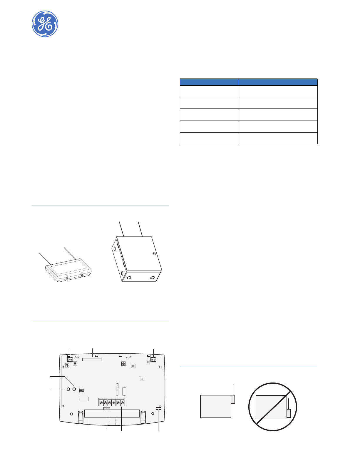
• two case versions (Figure 1), 60-821-95 (plastic) and
60-856-95 (metal).
Figure 1. Model cases
60-821-95
plastic case model
Figure 2 shows the transceiver components (plastic case version
shown) and Table 1 describes the components.
Figure 2. Transceiver components
Antenna
terminal
SuperBus
ID label
ID: XXXXXXXX
60-856-95
metal case model
Antenna
terminal
Table 1. Transceiver components
Component Description
Antenna terminals Provide antenna connections (outer termi-
Unique SuperBus 2000 ID label Indicates the unique identif ication number
Module power LED On when module is powered, flickers when a
Bus status LED Flashes when the transceiver communicates
Wiring terminals Connections for power, bus, and hardwire
nals are used with optional metal enclosure).
of the module.
wireless signal is received.
with the panel via the SuperBus.
zone.
Tools and supplies
You will need the following tools and supplies to install the
transceiver:
• Mounting screws and anchors for plastic enclosure
(included).
• Two 9-in. (22 cm) antennas (included).
• Two antenna grounding screws (included in metal case kit).
• 1/4 in. plastic spacers (included in metal case kit).
• Small standard and Phillips screwdrivers.
• Four-conductor, 18-gauge or larger, stranded hookup wire
(recommended).
Installation
Use the following guidelines to install the transceiver:
• Advent systems can accommodate up to 250 sensors/zones.
Refer to your panel documentation for maximum zone
count.
• Advent systems can have up to 62 SuperBus devices.
• Leave at least 10 in. (25 cm) above the transceiver for the
antennas.
• Avoid areas that expose the transceiver to moisture.
• Use 4-conductor, 18-gauge or larger stranded wire from the
transceiver to the panel.
For power wiring, refer to your panel documentation for
maximum wire length recommendations. If the maximum
recommended wire length must be exceeded, a remote DC
power supply is required. When using a remote power
supply, the power and ground connections of panel and
remote supplies must remain isolated and the power supply
output must be isolated from earth ground. Do not connect
the panel and remote power supplies together.
• Avoid areas with excessive metal or electrical wiring,
including furnace and utility rooms. If unavoidable, mount
on or near metal with the antennas extending above the
metallic surfaces (Figure 3).
Status
LED
Power
LED
Wire
access
Card
latch
Wiring
terminals
Card
latch
Figure 3. Mounting near metal
Metal
Metal
Page 2
SuperBus 2000 Commercial RF Transceiver
2
Installation Instructions
• Mount the transceiver on any interior wall (protected from
the elements).
• If possible, temporarily mount, connect, and test the RF
transceiver at the desired location to evaluate performance
in the particular environment.
Plastic case module installation
To install the module in the plastic case (60-821-95), do the
following:
1. Disconnect the panel backup battery and turn off power to
the AC power transformer.
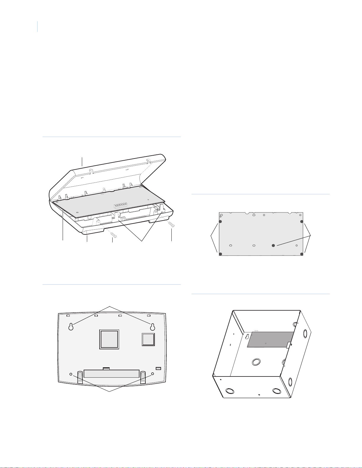
2. Remove the transceiver cover and the circuit board and set
them aside (Figure 4).
Figure 4. Remove cover and circuit board
Cover
Antenna installation
To install the antennas, do the following:
1. Loosen the inside terminals of the left and right antenna
terminal block (Figure 2 on page 1).
2. Insert an antenna into each inside terminal.
3. Tighten the antenna terminal screws.
Metal case installation
To install the module in the metal case (60-856-95). do the
following:
1. Remove the metal case cover and transceiver circuit board,
and set aside.
2. Hold the case against the mounting surface and mark the
four (larger) mounting holes. Remember to leave at least 10
in. (25 cm) above the case for the antennas.
3. Drill the mounting holes in the wall and insert the appropriate anchors.
4. Remove the case wiring knockouts as necessary.
5. Secure the case to the wall with panhead screws.
6. Snap the 1/4 in. plastic spacers (included) into the back of
the circuit board (Figure 6).
Figure 6. Plastic spacers
Circuit
board
Backplate
Cover
screws
Card
latches
Cover
screws
3. Hold the backplate against the mounting surface and mark
the four mounting holes (Figure 5). Remember to leave at
least 10 in. (25 cm) above the base for the antennas.
Figure 5. Mounting holes
Mounting holes
Mounting holes
Plastic
Plastic
spacers
spacers
7. Snap the circuit board into the case (Figure 7).
Figure 7. Snap the circuit board in the metal case
Plastic
spacers
4. Drill holes and insert appropriate anchors.
5. Secure the backplate to the wall with panhead screws.
6. Snap the circuit board back into the backplate.
Page 3

3
Antenna installation
To install the antennas in the metal case, do the following:
1. Loosen the left and right antenna terminal blocks
(Figure 8).
Figure 8. Metal case antenna installation
Antennas
Antenna
grounding
screw
Antenna
terminal
block
Antenna
terminal
block
Antenna
grounding
screw
2. Screw an antenna grounding screw (included) into each
outside terminal.
3. Insert an antenna into each inside terminal.
4. Tighten the antenna and ground terminal screws.
Wiring
This section describes how to wire the transceiver to compatible
panels and how to wire the transceiver hardwire zone input
terminals.
CAUTION: Improper connections can result in
damage to the equipment.
Advent panel wiring
Wire the transceiver to the panel SuperBus wiring harness as
shown in Figure 9.
Hardwire zone wiring
Connect the module Zone 1 and Zone Com terminals to the hardwired device as shown in Figure 10 using 2.0 Kohm EOL resistors (49-467) on the last device.
Figure 10. Hardwire zone wiring
SuperBus commercial
RF transceiver module
Zone 1 Zone COM
(OR)
UL listed
normally closed (N/C)
contacts in series
EOL resistor
EOL resistor
UL listed
normally open (N/O)
contacts in parallel
Module device address
Each bus module connected to the panel SuperBus must have a
unique (different) device address number set for correct communication. SuperBus 2000 compatible panels such as Advent set
the address automatically when the module is added (learned)
into panel memory.
Figure 9. SuperBus wiring harness connections
SuperBus commercial
RF transceiver module
+12VDC Bus A Bus B GND
To other
SuperBus
devices
Black
White
Green
Red
Panel SuperBus
wiring harness 46-462
Power up
Splice
Use the following procedures for powering up the system and
verifying bus communications for both new and existing installations.
New installations
To power up the system in new installations, do the following:
1. Verify that all wiring at the panel and the transceiver is
correct.
2. Connect the panel backup battery and the AC power transformer. Alphanumeric touchpad displays should come on.
3. Verify that the transceiver module green power LED is on
and the red bus LED flashes to indicates successful communication with the panel (Figure 2 on page 1).
Note: If the transceiver power LED is not on or the red bus
LED does not flash, unplug the panel AC power
transformer, disconnect the backup battery, and see
Troubleshooting on page 4.
Page 4

SuperBus 2000 Commercial RF Transceiver
4
Installation Instructions
Existing installations
To power up the system in existing installations, do the
following:
1. Verify that all wiring at the panel and the transceiver is
correct.
2. Connect the panel backup battery and the AC power transformer. Alphanumeric touchpad displays should come on.
3. Press 8 to select System menu.
4. Press 0 to enter program mode.
5. Enter the install code (defaults to 0123).
6. Enter item number 48001 to add SuperBus devices. All
installed devices are automatically added (learned) into
panel memory when Devices Added is indicated.
7. Press * twice to return to normal mode of operation and
refer to the testing sensors/inputs section of your panel
documentation for testing module operation.
8. Verify that the transceiver module green power LED is on
and the red bus LED flashes to indicate successful communication with the panel.
Note: If the transceiver power LED is not on or the red bus
LED does not flash, unplug the panel AC power
transformer, disconnect the backup battery, and see
Troubleshooting.
Programming
Refer to your panel documentation for adding (learning) wireless
devices into panel memory.
Testing
Verify that the module red bus LED flickers when wireless
devices are activated. Verify that the panel recognizes wireless
device and hardwire zone actuation (if used).
For complete testing procedures, refer to your panel documentation.
Troubleshooting
The module green power LED stays off.
Check for incorrect wiring connections and for panel power.
If the module power LED still stays off, replace the trans-
ceiver.
The module green power LED is on, but doesn’t flicker when
wireless transmitters are tripped (no or limited wireless operation).
Check transceiver antenna connection.
Check for transceiver antenna proximity to metal obstruc-
tions such as duct work or AC wiring.
Verify sensors are learned into panel memory.
If the transceiver still malfunctions, replace the module.
The red bus status LED flashes, but system does not respond.
Check panel/transceiver programming.
Delete transceiver from panel memory and relearn. Refer to
the Advent panel installation instructions for specific
details.
If the transceiver still malfunctions, replace the module.
Wireless device compatibility
The transceiver is compatible with the wireless devices listed in
Tab le.
Table 2. Compatible wireless devices
Part number Description
60-348 Learn mode handheld wireless touchpad
60-362 Learn mode door/window sensor
60-452 Learn mode pendant panic sensor
60-453 Wall-mount wireless touchpad
60-457 Dual-button panic sensor
60-458 Single-button panic sensor
60-459 Sound sensor
1 Rate-of-rise heat sensor
60-460
60-461 Learn mode shock sensor (with 13-214 detector)
60-462 Learn mode glass guard sensor
60-499 Learn mode SlimLine door/window sensor
60-504 Learn mode freeze sensor
60-506
1 Learn mode smoke sensor (System Sensor) 2001RF
60-511 Learn mode DS924i PIR motion sensor
60-578 Water-resistant pendant panic sensor
60-589 Learn mode fire pull station sensor
60-597 HiTech handheld wireless touchpad
60-606 Four-button keychain touchpad
60-607 Two-button keychain touchpad
60-615 Quik Bridge learn mode repeater
60-641 Learn mode long life door/window sensor
60-652 Carbon monoxide sensor
60-688 Learn mode micro door/window sensor
60-703 PIR motion sensor
60-741 Learn mode recessed micro door/window sensor
60-834 Learn mode FlexGuard sound sensor
60-848
1 Wireless smoke sensor (for UL 217 listed residential installa-
60-849
1 Wireless smoke sensor (for UL 268 listed commercial instal-
1. Learn mode repeaters are not UL 864 listed. All wireless fire devices (rate-ofrise heat sensors and smoke sensors) cannot be used with repeaters. Fire
sensor signals transmitted from repeaters cannot be processed by the RF
transceiver.
tions)
lations)
Page 5

5
FCC compliance
FCC part 15 information to the User
Changes or modifications not expressly approved by GE Security can void the
user’s authority to operate the equipment .
FCC part 15 class A
This equipment has been tested and found to comply with the limits for a class
A digital device, pursuant to part 15 of the FCC rules. These limits are designed
to provide reasonable protection against harmful interference when the equipment is operated in a commercial environment .
This equipment generates, uses, and can radiate radio frequency energy and, if
not installed and used in accordance with the instruction manual, and may
cause harmful interference to radio communications. Operation of this equipment in a residential area is likely to cause harmful interference in which case
users will be required to correct the interference at their own expense.
FCC part 15 class B
This equipment has been tested and found to comply with the limits with a class
B digital device, pursuant to part 15 of the FCC rules. These limits are designed
to provide reasonable protection against interference in a residential installation.
This equipment generates, uses, and can radiate radio frequency energy and, if
not installed and used in accordance with the instructions, may cause harmful
interference to radio communication. However, there is no guarantee that interference will not occur in a particular installation.
If this equipment does cause harmful interference to radio or television reception, which can be determined by turning the equipment off and on, the user is
encouraged to try to correct the interference by one or more of the following
measures:
Reorient or relocate the receiving antenna.
Increase the separation between the equipment and receiver.
Connect the affected equipment and the panel receiver to separate outlets,
on different branch circuits.
Consult the dealer or an experienced radio/TV technician for help.
Specifications
Compatibility Advent panels (60-562-01, 60-562-02, 60-
Number of wireless sensors Limited to the maximum capacity of the
Hardwire zones One class B, style A supervised, fire-rated,
Power required 12 VDC nominal at 50 mA maximum (from
Data bus SuperBus 2000, auto-addressing digital data
Data bus range Up to 4,000 ft . (1219 m) from panel, 18 gauge
Signal range 3,500 ft. (1067 m) typical in metal case,
Operating temperature 32 to 120°F (0 to 49°C) for extended periods,
Storage temperature -30 to 140°F (-34 to 60°C)
Max. relative humidity 90% noncondensing
Dimensions (L x W x D)
60-821-95 commercial burg
60-856-95 commercial fire
Case material
60-821-95
60-856-95
Listings UL 365: Police Connected Burgl ar Alarm Units
562-03), GE Security 319.5 MHz crystal learn
mode wireless sensors and touchpads, all dry
contact-type hardwire contacts
panel
normally open or closed dry contact zone
input
panel)
bus
or larger hookup wire
open air
2,500 ft. (762 m) typical in plastic case,
open air
(may vary with application)
up to 140°F (60°C) under temporary conditions
6.0 x 8.5 x 1.5 in. (152 x 216 x 38 mm)
11.25 x 9.75 x 4.63 in. (285 x 248 x 118 mm)
excluding antennas
High-impact, ABS plastic
16-gauge steel
and Systems
UL 609: Local Burglar Alarm Units and
Systems
UL 985: Household Fire Warning System
Units
UL 1023: Household Burglar Alarm System
Units
UL 1610: Central Station Burglar Alarm
System Units
ULC Canada Commercial Fire/Burglary
Warning System (applied for)
CSFM California State Fire Marshall
DOD Sensitive Compartment Information
Fac. (applied for)
FM Factory Mutual (applied for)
MEA New York City Material Equipment
Acceptance (applied for)
Complies with NFPA for Fire Alarm Code
Toll-free: 888.GESECURity (888.437.3287 in the US, including Alaska and Hawaii; Puerto Rico; Canada).
Outside the toll-free area: Contact your local dealer.
Technical support
www.gesecurity.com
 Loading...