

Page 1
Power Line Carrier Card
Document Number: 466-1518 Rev A.
March 1998
60-755
INSTALLATION
INSTRUCTIONS
Product Summary
The Power Line Carrier Card provides X-10 lamp
module and wireless siren features with a plug-in
®
card that is compatible with the following ITI
Learn Mode™ security panels:
■ Concord Hybrid Control Panel (60-734)
■ Concord RF16 Wireless Control Panel (60-
735-95R)
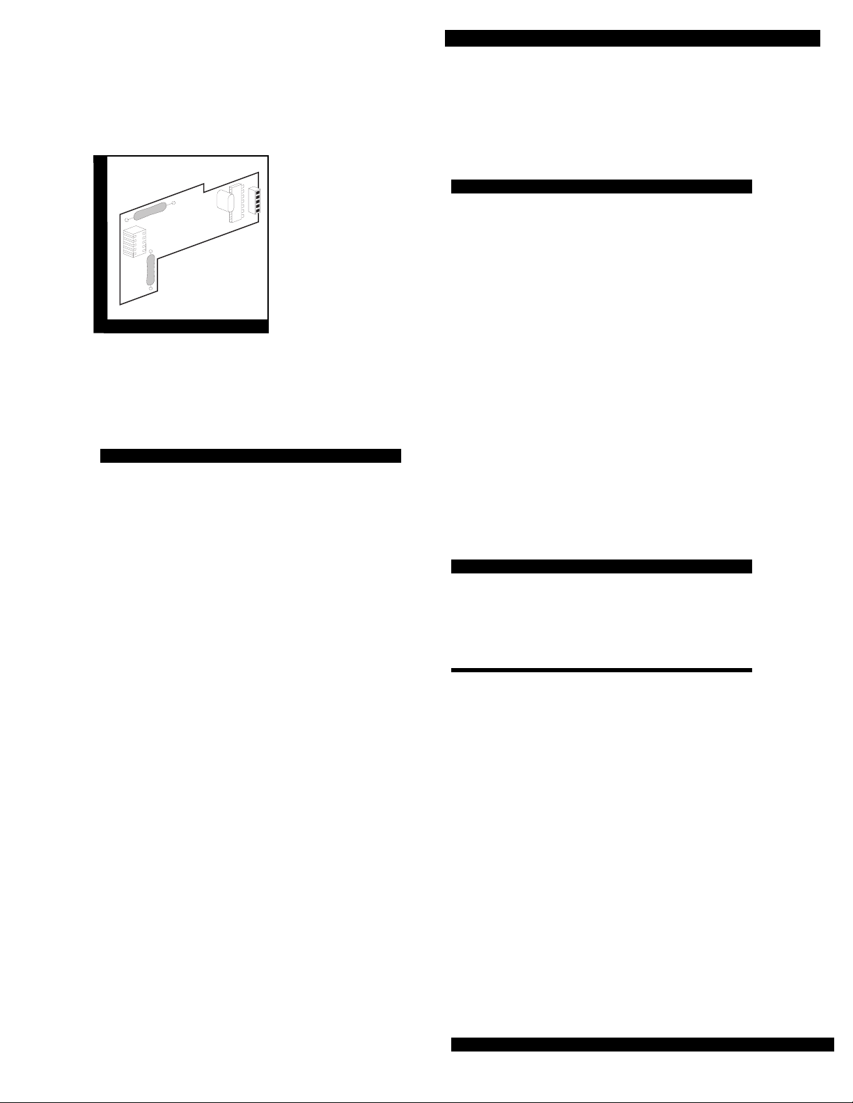
Power Line Carrier Card
Installation Guidelines
Follow the installation guidelines listed below:
■ The panel must be powered by a Line Carrier
Power Transformer (P/N 60-762 or 60-779)
■ Use 22 AWG (or larger) stranded wire to
connect the transformer to the panel
■ All X-10 modules and ITI Sup ervised Wireless
Sirens must be plugged into electrical outlets
on the same electrical phase
■ Avoid plugging the ITI Supervised Wireless
Sirens, transformers, and X-10 Lamp Modules
into outlets that share major appliances, such
as computers, microwave ovens, refrigerators,
dryers, or washing machines
■ The Power Line Carrier Card, X-10 Lamp
Modules, and sirens require a programmed
house code in order to operate
Installation
This section describes how to install the Power
Line Carrier Card.
Additional features include the following:
■ Communication with ITI Supervised Wireless
Sirens and X-10 modules via existing AC
electrical wiring
■ Simple “plug-in” functionality
■ Adds ITI Supervised Wireless Sirens
compatibility for sirens in the event of an
alarm
■ Adds X-10 module compatibility for light
control
■ Light control by turning lights on either
individually, simultaneously, or through
programmed time schedules
Installing in Concord Systems
Complete the following steps to install the Power
Line Carrier Card in both the Hybrid and Wireless
Concord systems:
1. Open the panel door.
WARNING:
2. Unplug the AC power transformer and disconnect the panel backup battery.
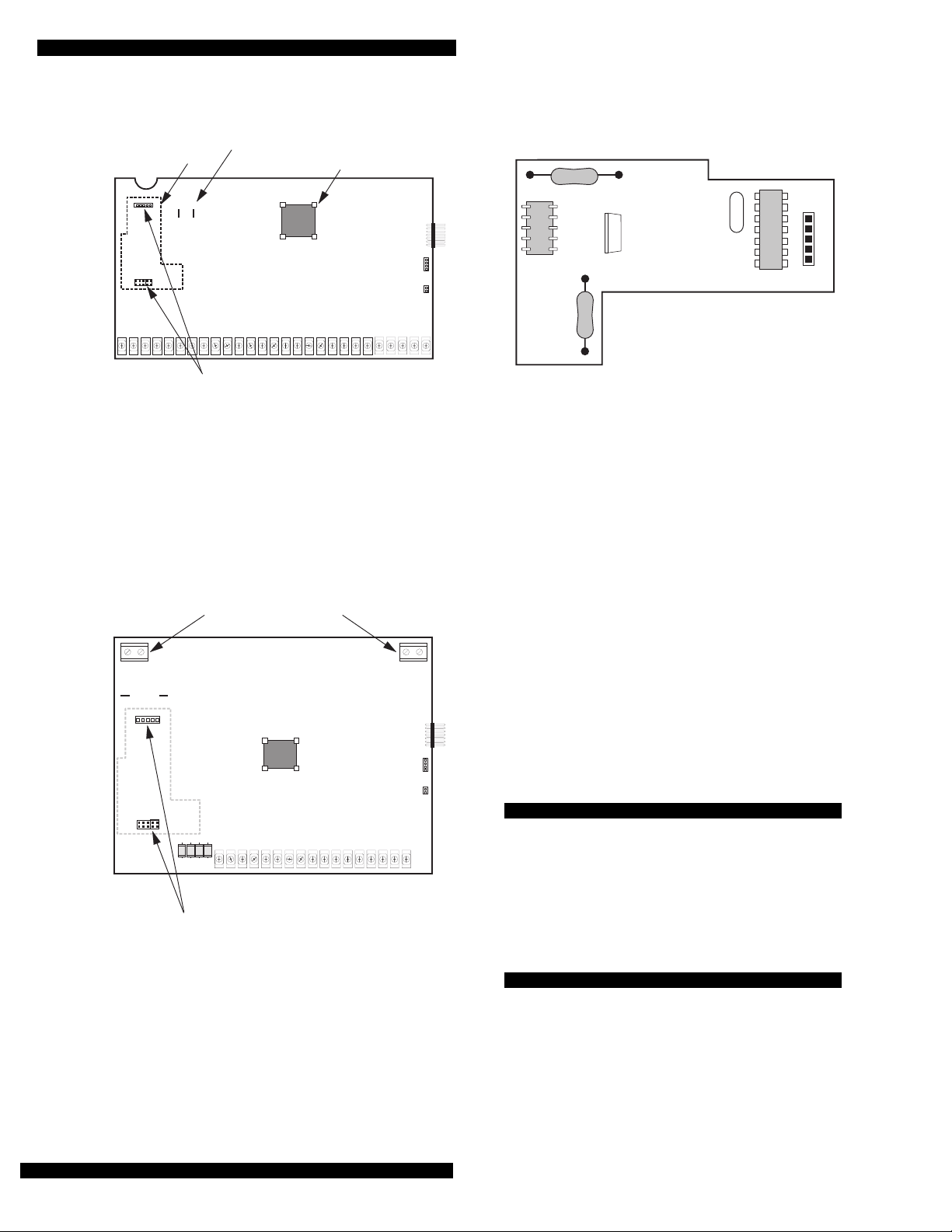
3. Remove both
tecting the Power Line Carrier Card headers on
the panel circuit board (see either Figure 1 or Figure 2).
Wear a grounding strap to prevent static
electricity damage to the card and panel.
1
/4” plastic jumpers that are pro-
Page 1
Page 2
Power Line Carrier Card
F
PHONE LINE
CARRIER CARD
BACKUP BATTERY
CONNECTIONS
–+
TERMINAL STRIP
MICRO
PROCESSOR
SNAP
CARD
HEADER
POWER LINE CARRIER
CARD HEADERS
8615G03A.DS
Figure 1. Concord Hybrid Panel Circuit Board
ANTENNAE CONNECTORS
PLC
CARD
+
BACKUP BATTERY
CONNECTIONS
MICROPROCESSOR
SNAP CARD
HEADER
–
8615G01A.DSF
Figure 3. Power Line Carrier Card
Note:
You can discard the jumpers, unless you plan
to eventually remove the Power Line Carrier
Card.
4. Insert the Power Line Carrier Card (see Figure 3)
solder side down and gently press into the panel
system board. (See either Figure 1 or Figure 2 fo r
the proper location of the Power Line Carrier
Card.)
5. Reconnect the panel’s backup battery and AC power transformer.
When the installation is complete, see the
“Testing” section of this manual.
Programming and Light Control
Page 2
TERMINAL STRIP
POWER LINE CARRIER
CARD HEADERS
8615G04A.DSF
Figure 2. Concord RF16 Wireless Panel Circuit Board
For complete programming information, refer to
the specific panel’s
Installation I nstructions
or the
ITI Supervised Wireless Siren’s Installation
Instructions.
Testing
Test ITI Supervised Wireless Sirens by arming the
panel, disarming it, bypassing sensors, etc. Test
light control by turning lights on and off
individually, simultaneously, or through
programmed time schedules.
Page 3

Power Line Carrier Card
Troubleshooting
Table 1 describes problems you may experience
after connecting devices to your panel. Possible
solutions are listed in the Cause/Action column.
Table 1. Troubleshooting
Problem Cause/Action
The light or siren will not
work.
The power transformer is
1.
not line carrier compatible.
Replace it with a Power
Line Carrier Transformer
(60-672 or 60-779).
The house code is not
2.
programmed into the panel,
ITI Supervised Wireless
Sirens, or X-10 modules.
Verify that the prope r house
code is entered for all components. Program the prop er
house code if necessary.
Specifications
Compatibility:
■ Concord Hybrid Control Panel
■ Concord RF16 Wireless Control Panel
P ower Requirements:
■ Input Voltages: +5 and +12 VDC
■ Output Voltages: 4.2 V, peak to peak, across
5 ohm load
■ Current Draw: Nominal = 110 mA
Idle = 10 µA
■ Dimensions: 2.95” x 1.95” x.875”
(7.49 x 4.95 x 2.22 cm)
■ Operating Temperature
10° to 120° F
(0° to 50° C)
Power Line Carrier isn’t
3.
seated cor rectly.
the card and gently press it
back onto the panel circuit
board.
Remove
Page 3
Page 4

Power Line Carrier Card
Notices
This equipment ha s been te sted and found t o comp ly with the limits for a class
B device, pursuant to part 15 of the FCC Rules. These limits are designed to
provide reasonable protection against harmful interference in a residential
installation. This equipment generates, uses, and can radiate radio frequency
energy and, i f n o t i nst a ll ed a nd us e d in a cco rd an ce with the inst ructions, may
cause harmful in terference to radio communic ations. However, there is no
guarantee that interference will not occur in a par ticular installation. If this
equipment does cause harmful interference to radio or television reception,
which can be determined by turning the equipment off and on, the user is
encouraged to try to correct the inte rference by one or more of the followi ng
measures:
■ Reorient or relocate the receiving antenna on the radio or TV.
■ Increase the separation between the equipment and receiver.
■ Connect the equipment into an outlet on a circuit different from that to
which the receiver is connected.
■ Consult the dealer or an experienced radio/TV technician for help.
Page 4
651/777-2690
651/779-4890
ITI is a registered trademark of Interactive Technologies, Inc.
Learn Mode and Concord are trademarks of Interactive Technologies, Inc.
 Loading...