

Page 1
600-1053-3 Concord 4 GSM Module Installation
Sheet
Description
Model numbers:
600-1053-3
600-1053-3-AT 600-1053-3-ZWAVE-AT
600-1053-3-TM 600-1053-3-ZWAVE-TM
The module interfaces with the Concord panel data bus and is
powered by the panel battery or an auxiliary 12 VDC power
supply. The module can be used on Concord 4.0 and higher. Status
LEDs indicate bus and paging network communications. A
supervised zone input allows you to connect a hard-wired contact.
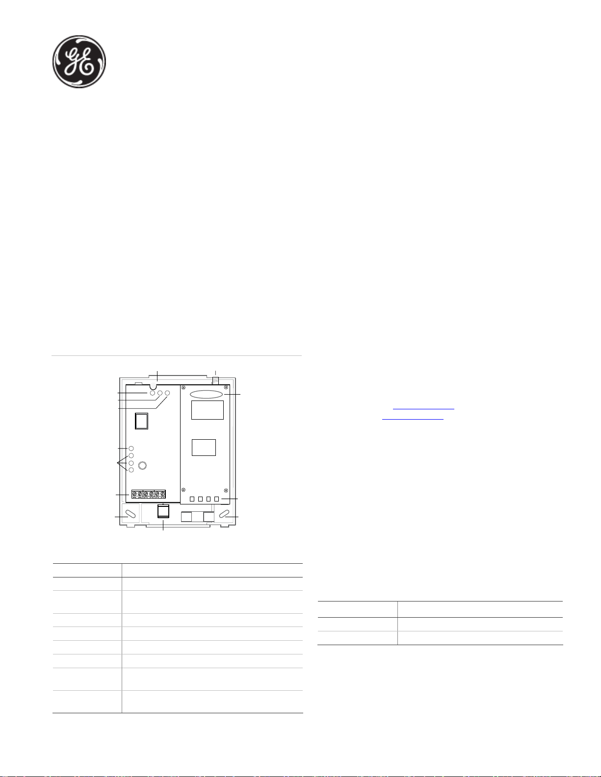
Figure 1 below shows the location of the main module
components and
Figure 1: Components
PWR LED
AUTO LED
Unused LED
Status LEDs
terminals
Mounting
hole
Table 1: Components
Component Function
PWR LED Indicates module power status.
BUS LED Indicates data bus activity between the panel and
AUTO LED Indicates module/data transceiver communication.
Status LEDs Indicates communication status with GSM network.
Wiring terminals Provides panel and zone wiring connections.
Antenna jack Antenna connection for wireless data transceiver.
GSM status LEDs Indicates communication with the GSM network,
Serial number A 15-digit number. Only the last 10 digits are used for
Table 1 describes the component functions.
Mounting hole
BUS LED
Wiring
Wire access area
module.
report errors, and signal strength.
account activation.
Antenna jack
SIM card
Serial
number
GSM status
LEDs
Mounting
hole
Use the following tips to ensure success with the Alarm.com
Concord GSM module:
• Make sure you create the customer account on the
Alarm.com dealer website at least 24 hours before
installation.
• Make sure you turn off the Access Code Lock feature.
• Use the LEDs on the module to check the signal strength
before you permanently mount the module.
• Power the module off the battery, not off the panel.
• Do a manual phone test to initiate communication (see
Power up” on page 3).
“
Account creation
Alarm.com recommends creating the customer account 24 hours
prior to installation to ensure that the GSM radio is activated. If
you are not currently an Alarm.com dealer, please visit the
Alarm.com website (
request, or email
www.alarm.com) and submit an information
info@alarm.com.
Installation
Before you install the system, the module must be activated. The
account creation process automatically activates the module
within 24 hours.
The module draws a maximum of 65 mA (continuous) from the
panel in power save mode, and 100 mA (continuous) from the
panel in idle and connected modes. Do not exceed the panel total
output power when using panel power for bus devices and
hardwired sensors (refer to the panel documentation).
Use four-conductor, 22 or 18 gauge stranded wire to connect the
module to the panel.
length for each gauge.
Table 2: Maximum wire length
Gauge Maximum wire length to panel
22 gauge 40 ft. (12.2 m)
18 gauge 90 ft. (27.4 m)
You will need the following tools and supplies to install the module:
• Small blade and Phillips screwdrivers
• Drill and bits for screws and/or anchors
• Wire cutter/stripper
• Four-conductor, 22-gauge or larger stranded wire
Table 2 below shows the maximum wire
P/N 466-2262 • REV D • June 2011 1
Page 2
• Wall anchors (four included)
• 2-Kohm EOL resistor (included)
Use the following guidelines to choose a location for the module:
• Check the signal strength before choosing a location. Do a
walking signal strength test by powering the module off the
battery directly (connect the GND and +12V terminals). After 2
minutes, GSM status LED 4 will flash between one and five
times, equivalent to the number of bars on a cell phone. We
recommend a signal level of two or higher.
• Do not mount the module within 6 ft (1.8 m) of panel.
• Avoid mounting the module in areas with excessive metal or
electrical wiring, such as furnace or utility rooms.
• Locate the module near an outside wall, preferably on an
upper level.
• Leave 12 to 18 in. (30 to 45 cm) of open space above the
module for the antenna.
• For homes or businesses located in canyons or with hills
nearby, it is necessary to place the antenna higher in the
building.
Caution: You must be free of static electricity before handling
electronic components. Touch a grounded metal surface before
touching the circuit board.
To mount the module:
1. Press down on the top of the enclosure cover, remove it, and
set it aside.
2. Screw the antenna onto the antenna jack (see Figure 1 on
).
page 1
3. Place the backplate on the wall at the desired mounting
location, check for level, and mark the three mounting holes
and the wire access area (see
Figure 1 on page 1). Be sure to
leave at least 12 to 18 in. (30 to 45 cm) above the backplate
for the antenna.
4. Set the backplate aside and drill holes at the mounting and
wire access area locations.
5. Use wall anchors where studs are not present and secure the
backplate to the wall with the enclosed screws.
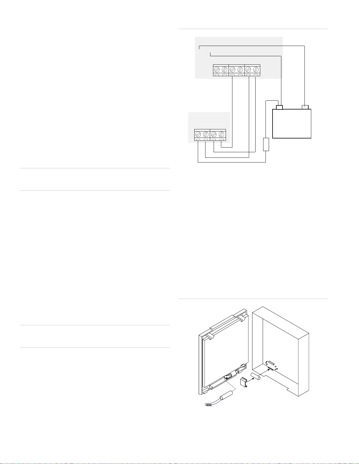
Figure 2: Wiring connections
Concord control panel or power supply 600-101 9
-+
16AC GND +12DC A B
Black
GSM module
+12V A B GND
Green
White
Red Black
10 amp fuse
+
12V battery
-
Case tamper switch
If the module is easily accessible, you can add case tamper
detection to activate an alarm or trouble (depending on panel
programming) when the cover is removed.
To install the tamper switch:
1. Slide the reed switch into the plastic holder on the module
backplate.
2. Connect a UL-Listed reed switch (with 2 Kohm EOL resistor
01-022) to the module zone input or to any unused hardwired
input on the panel.
3. Insert the magnet into the nibs on the top cover and press
the magnet clip down over the magnet until it clicks into
place into the cover.
Figure 3: Case tamper switch
Backplate
Cover
Wiring
Caution: To prevent damaging the panel or module, you must
remove panel AC power and disconnect the backup battery before
making or changing wiring connections.
To wire the module:
1. Remove AC panel power and disconnect the backup battery.
2. Wire the module to the panel bus and to the battery
terminals for power. (The module can also be powered off the
SuperBus 2000 two-amp power supply (600-1019), but should
not be powered directly off the panel.)
3. You can connect an input device to the module ZI and ZCOM
Reed switch
2.0 kohm EOL resistor
terminals if required.
2 600-1053-3 Concord 4 GSM Module Installation Sheet
Magnet
Magnet clip
Page 3
Power up
You will need to power up the module and panel to start
communication between them.
To power up:
1. Verify that all wiring between the panel and module is
correct.
2. Connect the backup battery and restore AC power to the
panel.
Whenever any module is added or changed, you must
remove panel power and reapply it for the panel and module
to communicate successfully.
3. Enter installer program mode and turn off the Access Code
Lock feature (in the Security menu).
This must be set to off for the system to communicate with
Alarm.com. The module PWR LED should turn on. After a few
seconds, the module BUS and AUTO LEDs should flash to
indicate successful communication with the panel.
4. Verify that GSM status LED 1 is not flashing any errors and
that LED 4 is at flashing at least a level of two.
Otherwise, relocate the module. If LED 1 and LED 4 are not
flashing at all, and LED 2 and LED 3 are flashing together, the
module is in power save mode and the battery needs to be
changed.
5. Do an installer GSM manual phone test (at system touchpad,
enter 8, installer code, 3). Disarm the panel by entering 1
<installer code> within 10 seconds of starting the phone test.
Before doing the manual phone test, the bottom red status
LED should be on and the yellow status LED should be
flashing. The yellow LED will stay on solid once the manual
phone test is completed.
Do not press any system touchpad buttons during the 5 to 8
minutes, or the time will not set. During this time, the keypad
will go in and out of programming mode and will beep
several times.
Green LED
• Off as soon as Alarm.com receives the message from the
module (off most of the time).
• Blinks when the message is being sent by the module.
Table 3 below describes status LED condition patterns.
Table 3: Status LED condition patterns
Number Red
1 Off Off Off Not powered up/not working.
2 On Off Off In range, first message not sent,
3 On On Off In range, first message sent, not
4 On On Blinks In range, first message sent,
5 On Blinks Blinks In range, sending first message,
6 Blinks On Blinks Out of range, first message sent,
7 Blinks On Off Out of range, first message sent,
8 Blinks Blinks Blinks Out of range, sending first
LED
Yellow
LED
Green
LED
Module condition
currently sending message.
currently sending message.
currently sending message.
currently sending message.
currently sending message.
not currently sending message.
message, currently sending
message.
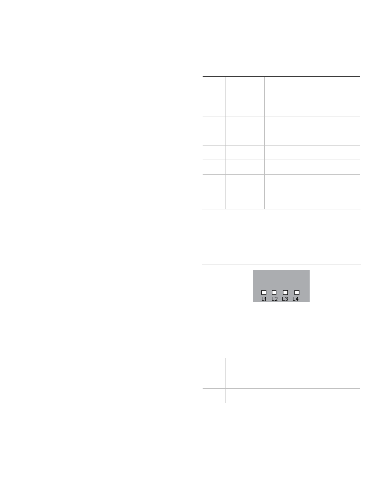
GSM status LEDs
The GSM status LEDs are four small LEDs located on the lower
right side of the module.
Figure 4: GSM status LEDs
Status LEDs
The status LEDs located on the left side of the module indicate the
current signal and the status of the wireless gateway module. The
bottom red LED indicates if the module is in range and if it is
registered. The yellow and green LEDs indicate the message
status. The top LED is not used.
Red LED
• On when the module is in range and registered with the
network.
• Off when the module is out of range and not registered with
the network.
• Blinks when the module is registered with the network, but
LED 1 (red). Flashes 1 to 8 times in an 8-second interval to
indicate specific error conditions. The number of flashes indicates
the error number. If there are two or more errors at the same time,
the errors will flash one after the other. The LED will stay off for at
least 4 seconds between errors.
Table 4: LED 1 errors
Flashes Error
1 flash Module cannot communicate with the panel. Check wiring
between the panel and the module. Make sure the bus wires
are not swapped.
2 flashes The SIM card is missing. The SIM cardholder can be found in
the gateway just below the antenna.
out of range.
Yellow LED
• On after the first message has been sent by the module and
received by Alarm.com.
• Off until a message has been sent by the module.
• Blinks when the first message is being sent by the module.
600-1053-3 Concord 4 GSM Module Installation Sheet 3
Page 4

Flashes Error
3 flashes This is a common error if the module takes more than 10
seconds to register with the GSM network. It is normal for this
error to show up for approximately 30 seconds while the
module registers with the GSM network (at power up, for
example). If it persists, the module is unable to register with the
GSM network. Check LED 4 for signal level. If the signal level is
too low, change the module’s location or use a higher gain
antenna. If the signal is good, the module may be roaming on
a GSM network that doesn’t partner with our ATT-Cingular. If
the module had been communicating in the past, there may be
new interference from some other device or building.
4 flashes The module is registered on the GSM network, but cannot
connect with Alarm.com. Contact Alarm.com technical
support.
5 flashes The radio portion of the module is not working correctly.
6 flashes This is an error only if it persists for more than a minute.
Otherwise, it is just an indication that the module is fixing an
unusual condition regarding communication with the GSM
network.
7 flashes Access Code Lock is on. The module cannot do certain
operations with the panel. This option should be turned off at
the panel (System Programming – 0003).
8 flashes Contact Alarm.com technical support.
LED 2 (yellow). Flashes with every communication between the
module and the panel. Normal pattern calls for a series of quick
flashes every 2 seconds in idle mode or every 4 seconds in power
save mode.
LED 3 (green). Flashes with every communication between the
module and its radio unit in idle mode, and with every
communication with Alarm.com in connected mode. In power
save mode, this LED flashes in unison with LED 2.
LED 4 (green). Indicates GSM signal level as a number of flashes (1
to 5). The signal level is updated every 8 seconds. No flashes
indicate one of the following:
• The module is in power save mode or in connected mode.
• The module is just powering up, or has just exited power save
mode.
• There is no GSM tower coverage in the area.
In connected mode, the LED toggles on and off.
Module modes
The module modes (states) include:
Idle mode. AC power is up, the battery level is greater than 11.5
volts, and the module is currently not connected to Alarm.com
servers. This is normal for the module and the most common
state.
• LED 1 flashes errors, if any.
• LED 2 indicates communication with panel.
• LED 3 indicates communication with radio unit.
• LED 4 indicates the signal level (1 to 5 bars).
Power save mode. The module just powered up, AC power is
down, or battery level is less than 11.5 volts. The radio part of the
module draws 10 mA in power save mode. It is fully functional and
will go into connected mode as soon as a signal needs to be sent.
Doing a manual phone test will switch the module into idle mode
and update the signal level reading.
• LED 1 is inactive.
• LED 2 indicates communication with panel.
• LED 3 flashes in unison with LED 2.
• LED 4 is inactive.
Connected mode. The module is connected to Alarm.com servers
and reported an alarm or other condition. The module stays in
connected mode for at least 6 minutes after the last message is
exchanged. Entering the panel’s Installer Programming mode will
cause the module to go into idle mode.
• LED 1 flashes errors, if any.
• LED 2 indicates communication with panel.
• LED 3 indicates communication with Alarm.com.
• LED 4 alternates 2 seconds on, then 2 seconds off.
Sensors 94, 95, and 96
If sensors 94, 95, and 96 are not learned in, after doing a manual
phone test, the text for these sensors will display important
information for troubleshooting purposes. Alarm.com technical
support staff may request this information during service calls.
• Sensor 96 text displays the SIM card number.
• Sensor 95 text displays the type of central station reports
enabled.
• Sensor 96 text displays the serial number.
Troubleshooting
Check GSM status LED 1 to see if it is flashing any errors. See
Table 4 on page 3 for descriptions of the errors indicated.
• The power LED (the green LED at the top of the module) is not
on.
Turn off the panel power and verify that all wiring is correct.
• Module status LEDs (on the left side of the module) do not turn
on immediately after initial power up.
You must wait 5 to 8 minutes after power up for the module
to communicate with Alarm.com.
Access Code Lock feature (in panel memory) must be turned
off for correct operation.
• Touchpads/sirens are beeping even though the system is not
armed.
Press the touchpad Status button and the panel reports the
status issue and stops beeping.
• The status LEDs (on the left side of the module) are all off.
Verify that there is GSM coverage in the location.
Do a walking signal test. Ensure that the module is correctly
powered off the battery.
If the wireless gateway module is powered down for a short
period, buffered messages may be received from the GSM
network when module power is restored.
The GSM module does support reporting of all touchpad panics,
but will not send touchpad numbers along with the cancel report.
This module does not support the keypad tamper feature at this
time.
4 600-1053-3 Concord 4 GSM Module Installation Sheet
Page 5

Z-Wave devices
Required items for installation
• Concord panel (software versions 4.0 and higher)
• Alarm.com Z-Wave-enabled GSM Module for Concord (600-1053-3-ZWAVE-TM or 600-1053-3-ZWAVE-AT)
• Z-Wave peripherals to be installed
Account creation and system setup
1. Create a new account on the Alarm.com Dealer Site (or swap the module into an existing customer account). Add the appropriate
emPower services (Lights, Thermostats, and/or Locks) on the service plan page. (Note that “Light Automation” refers to X10 and is not
compatible with emPower.)
2. Install the Alarm.com Z-Wave-enabled GSM Module and gateway, connecting it to the Concord panel.
3. Perform a GSM test at the panel to initiate communication between the module and Alarm.com.
Make sure to install the Alarm.com module and gateway outside the metal can. If it is inside the can, this will negatively impact ZWave signal transmission.
Figure 5: Z-Wave module overview
600-1053-3 Concord 4 GSM Module Installation Sheet 5
Page 6

Adding z-Wave devices
Make sure the Concord panel is connected to AC power when
enrolling Z-Wave devices.
When adding devices, first add the devices closest to the
Alarm.com system, and then move outwards.
Devices must be within 6 ft of the Alarm.com module when adding
it to the network, Install each of the Z-Wave peripherals in their
desired locations, following the manufacturer’s instructions. Then
follow the instructions to add (include) each device into the
Alarm.com module’s network. If a device will not be within 6 ft. of
the Alarm.com module in its permanent installation location,
include it in the network before installation or use a controller
(controllers are not available for locks, see below).
If installing a portable Z-Wave controller, first add the controller to
the Alarm.com Z-Wave network using the Concord panel, and
then use the portable controller to add the remaining devices to
the network while the devices are in their permanent locations.
(Locks cannot be added to the controller, and will need to be
added by the Alarm.com module.) Devices must be within 6 ft. of
the controller if a controller is being used to learn in devices.
Add a Z-Wave device to the Alarm.com module’s network (Device Inclusion)
1. Put the Alarm.com module into Z-Wave Add mode.
On the Alarm.com module, press and hold down the Z-Wave
Mode button for a few seconds, until the Busy LED begins
flashing a 4-blink pattern to indicate Z-Wave Add mode. (See
Figure 5 on page 5) for illustration of how to press the button.)
Or,
Use a portable Z-Wave controller to add devices to the
network. (See the section on Controllers for details).
2. Press buttons on the Z-Wave device to add.
Once the module (or controller) is in Z-Wave Add mode, press
the appropriate buttons on the Z-Wave device to add it to the
network. See Device-specific instructions (or the instructions
that came with the device) for more information.
3. Confirm the Z-Wave device is added successfully.
Once the device has been added successfully, the panel will
beep, and the orange Busy LED on the Alarm.com module’s ZWave board will become solid and stay solid for 1 minute
(allow up to 5 seconds for confirmation once the device has
been triggered).
To add another device, repeat the steps above. (You do not need
to wait for the solid light to go away before holding down the
Alarm.com Z-Wave button to enter Add mode again.
See “
Z-Wave Troubleshooting” on page 9 for more information on
interpreting the Z-Wave LEDs on the module.
Checking the Devices list with Alarm.com
Once you’ve added the devices, the customer website will
automatically update the Devices list (under the emPower tab)
within about 2 minutes of the last device being added. (To
manually trigger the update sooner, you can perform a GSM
phone test at the panel.) You can also view the Z-Wave devices
through the Alarm.com Dealer website by pulling up the customer
account and clicking on the emPower Devices link in the left-hand
navigation.
Testing device communication with Alarm.com
Once the Z-Wave devices have been installed in their permanent
locations and are displayed in the device list on Alarm.com, we
recommend sending a remote command to each device (e.g., turn
on a light; adjust the target temperature at a thermostat) to verify
that it is successfully communicating with the Alarm.com module.
If you are onsite at the customer location and do not have access
to the website, you can also check communication using the ZWave Busy LED. When the Alarm.com module is in Normal mode
(i.e. not in Add/Delete mode), its Busy LED is by default off, but
issues a single flash whenever it receives a message from a device
in its own Z-Wave network. if a device is next to the panel, you can
use this feature to test whether or not the device is currently
installed on the Alarm.com Z-Wave network, and whether or not it
is communicating properly.
To check communication between a Z-Wave device and the Alarm.com module:
1. Ensure that the Z-Wave device is powered on, and then press
the same button you would use if you were trying to add it to
a network (check the device’s installation instructions if you
are unsure which button to press).
2. The Busy LED on the module will issue a quick single flash to
indicate it has heard the signal form the device. If the Busy
LED does not flash when the device’s button is pressed, this is
most likely because of one of the following: a) the device is
not in the Alarm.com module’s Z-Wave network; b) it is out of
direct communication range form the Alarm.com module; or
c) the device is not powered on or working properly.
Deleting a Z-Wave device (Device Exclusion)
You can enter Delete mode to:
• Delete a Z-Wave device from the Alarm.com module’s ZWave network if you no longer want the device in the
network (e.g., if it is no longer in use).
• Delete a Z-Wave device from a different network so that it
can then be added into the Alarm.com network. (A given ZWave device and only be assigned to one Z-Wave network at
a time. If it is already assigned to one network, it needs to be
deleted from one network before it can be added to another
network.)
Whether you are deleting a device from the Alarm.com module’s
Z-Wave network or another Z-Wave network, the steps are the
same.
1. Put the Alarm.com module into Z-Wave Add mode.
On the Alarm.com module, press and hold down the Z-Wave
Mode button to enter Add mode (4-blink pattern on the Busy
LED). Once in Add mode, press and hold down the Z-Wave
Mode button again until the Busy LED begins flashing a 2blink pattern to indicate Z-Wave Delete mode. (See
Figure 5
on page 5 for illustration of how to press the button.)
2. Press buttons on the Z-Wave device to delete.
Once the module (or controller) is in Z-Wave Delete mode,
press the appropriate buttons on the Z-Wave device to add it
6 600-1053-3 Concord 4 GSM Module Installation Sheet
Page 7

to the network. See Device-specific instructions (or the
instructions that came with the device) for more information.
3. Confirm the Z-Wave device was deleted successfully.
4. Once the device has been deleted successfully, the panel will
beep, and the orange Busy LED on the Alarm.com module’s ZWave board will become solid and stay solid for 1 minute
(allow up to 5 seconds for confirmation once the device has
been triggered).
If a device is not longer functioning, you can also delete it through
the Device Automation page on the Alarm.com Dealer website.
Send a remote command to the device and wait a few minutes for
the command to register as failed. The failed device will have a
remote node link next to it.
emPower on the Alarm.com Dealer website
Through the Alarm.com Dealer Website you can modify the
emPower service plan, view the Z-Wave device list, and order
emPower modules and devices. To add or remove emPower
features from your customer’s service plan, go to the customer’s
service plan page and check the features (lights, locks, thermostat,
or the energy package - lights and thermostat) that you would like
to add/remove. To view a list of your customer’s Z-Wave devices,
pull up their account and click the “emPower Devices” link.
Device-specific instructions
Controllers
Advanced Remote Controller
Note: if a controller will be used with the system, Alarm.com
recommends adding it before the rest of the Z-Wave devices.
Refer to the instructions that came with your controller for more
information on controller features and operation.
To add the controller to the security panel (system):
1. Enter your panel into Add mode.
2. With the controller close to your panel, press and hold the
Setup button on the controller until the controller screen
displays “Lights Setup”.
3. Use the arrow buttons to scroll until you see “Transfer” on the
controller screen. Press the OK button.
4. The controller screen should now display “Primary”. Use the
arrow buttons to scroll until you see “Receive”.
5. Press the OK button. The controller screen should display
“Receiving”.
6. The controller screen will briefly display “Success” after the
controller has been successfully included into the panel.
To add a light module to the system using the controller:
1. Press and hold the Setup button on the controller until the
screen displays “Light Setup”. Press the OK button.
2. The controller screen should now display “Add”. Press the OK
button.
3. The controller screen should now display “To Network”.
4. Use the arrow buttons to scroll until you see “To a Key” and
then press the OK button.
5. Press a number key 1 to 9 or Setup (Shift) and a number key
for numbers 10 to 18.
6. Press the OK button and the screen should now display
“Setup Waiting”.
7. Double-click the button on the light module. The controller
screen will briefly display “Success” to confirm you have
added the device to the controller key and system network.
Note: To add a light module using the controller without adding it
to a specific number key on the controller, skip steps 4 and 5.
To add a thermostat to the system using the controller:
1. Press and hold the Setup button on the controller until the
screen displays “Light Setup”.
2. Use the arrow buttons to scroll until the screen displays
“Thermostat”. Press the OK button.
3. The screen should now display “Add”. Press the OK button.
4. The screen should now display “Setup Waiting”. Follow the
device-specific directions for the thermostat you are adding
to the system to trigger it. The controller screen will display
“Success” to confirm you have successfully added it to the
system network.
To remove a light module from the system network using the controller:
1. Press and hold the Setup button on the controller until the
screen displays “Light Setup”. Press the OK button.
2. The controller screen should now display “Add”. Use the
arrow buttons to scroll until you see “Delete”. Press the OK
button.
3. Double-click the button on the light module. The controller
screen will briefly display “Success” to confirm you have
removed the device from the controller key and system
network.
To remove the thermostat from the system network using the controller:
1. Press and hold the Setup button on the controller until the
screen displays “Light Setup”. Press the OK button.
2. Use the arrow buttons to scroll until the screen displays
“Thermostat”. Press the OK button.
3. The controller screen should now display “Add”. Use the
arrow buttons to scroll until you see “Delete”. Press the OK
button. The screen should now display “Setup Waiting”.
4. Follow the device-specific directions for the thermostat that
you are removing from the system to trigger it.. The controller
screen will briefly display “Success” to confirm you have
removed it from the system network.
To delete the controller from the security panel (system):
1. Enter your panel into Delete mode.
2. Follow steps 2 to 5 in the instructions for “
controller to the security panel (system):
3. The controller screen will briefly display “Success” after the
controller has been successfully deleted from the panel.
To add the
” above.
600-1053-3 Concord 4 GSM Module Installation Sheet 7
Page 8

Lights and appliances
Plug-in Lamp Module or Plug-in Fluorescent Light/Appliance Module
1. Plug in the device.
2. Enter Add mode on the security panel.
3. To add the device, double-click the button in the middle of the
light or appliance module. (If there is no beep at the panel
confirming successful enrollment of the device, try pressing
the button again.)
Tips
• Lamp modules cannot be used with compact fluorescent
bulbs (CFBs). Use appliance modules instead.
• Make sure the lamp to be controlled is plugged into the ZWave side of the module (indicated by the Z-Wave logo).
• We recommend using a non-switched outlet for the module.
If using an outlet controlled by a switch, make sure the outlet
is switched on before sending light commands.
• Keep lamps switch on to allow control through the Z-Wave
module, Alarm.com website, and mobile applications.
• Control dimming of lamp modules by pressing and holding
the button on the module, or through the Alarm.com website
In-Wall Dimmer Light Switch or In-Wall On/Off Light Switch
1. Follow the provided directions to install the device and ensure
that it functions properly with manual on/off control.
2. Enter Add mode on the security panel.
3. To add the device, turn on and turn off the light switch. (If
there is no beep at the panel confirming successful
enrollment of the device, try turning the device on and off
again.)
Locks
Note: If the security panel cannot be taken to within 6 ft. of the
lock installation location, add the lock to the system first as
directed beginning in step 2. (You will need to connect the battery
pack to the keypad before attempting to perform these steps.)
Tips
• Before removing old locks or beginning installation, check the
layout of the door to make sure the new lock will not conflict
with existing hardware.
• Contact a locksmith if you experience difficulties removing
old hardware or installing the new lock.
• Send user codes to the lock (via the customer website - see
step 4) before leaving the property. Alarm.com does not
recommend programming codes locally via the lock keypad all codes should be programmed through the Alarm.com
interface.
• Ask your customer to save the programming code that
comes with the lock (Schlage only). This will be convenient to
have if they ever have issues in the future.
Schlage lever lock or Schlage deadbolt
1. Follow the instructions included with the lock. When
prompted to continue setup online, do the following steps to
program the lock into the Concord panel.
2. Enter Add mode on the security panel.
3. On the lock keypad, enter the six-digit programming code
(given by Schlage), then press the Schlage button, followed by
0. The Schlage button will flash green (
Note: Wait until the light flashes green before disrupting the
lock or panel. Failure to do so will result in lock malfunctions.
Figure 6: Schlage lock
Figure 6 below).
Tips
• Dimmer switches and on/off switches cannot be
interchanged. Use the appropriate type of switch.
• If it is not practical to move the security panel 3 to 6 ft. to the
device, consider investing in a controller for installations.
In-Wall Outlet Receptacle
1. Follow the provided directions to install the device and ensure
that it functions properly with manual control.
2. Enter Add mode on the security panel.
3. To add the device, double-click the button in the middle of the
outlet. (If there is no beep at the panel confirming successful
enrollment of the device, try double-clicking the button
again.)
Tips
• If it is not practical to move the security panel 3 to 6 ft. to the
device, consider investing in a controller for installations.
• We recommend using a non-switched outlet for the Z-Wave
outlet. If using a switch outlet, make sure the outlet is
switched on before sending commands.
• Only the lower outlet is controlled by Z-Wave. Ensure you are
plugging devices into the lower outlet while testing if the
outlet works for Z-Wave control. The opposite is true if the
device is installed upside down.
4. Login online to the customer account at www.alarm.com to
select which user codes are allowed to use this lock. To do
this, go to the emPower then Locks tab. On the User Code
table, you will see a column labeled Lock Access. Check the
box of the lock you want to allow each user code to access.
Tip
If you observe a red blinking light at the end of the installation
keystrokes instead of green, follow these instructions:
1. Enter the panel into Delete mode (see “
device (Device Exclusion)
” on page 6).
Deleting a Z-Wave
2. Enter the six-digit programming code on the keypad and wait
for three orange lights and three beeps.
3. Press the Schlage button and then 0 on the keypad. Wait for
three orange lights and three beeps.
8 600-1053-3 Concord 4 GSM Module Installation Sheet
Page 9

4. Wait for all lights to stop blinking. You should now be able to
enroll the lock normally by repeating the steps shown above
(after re-entering Add mode).
Kwikset deadbolt
1. Follow all instructions provided to install the lock onto the
door and doublecheck that the programmable keypad lock
works.
2. Enter the panel into Add mode.
3. To trigger the lock to add it, press button “B” (
Figure 7 below).
Note: Wait until the red light (under the paper next to button
“B”) stops flashing before disrupting the lock or panel. Failure
to do so will result in lock malfunctions.
4. Login online to the customer account at www.Alarm.com to
select which user codes are allowed to use this lock. To do
this, go to the emPower then Locks tab. On the User Codes
table, you will see a column labeled Lock Access. Check the
box of the lock you want to allow each user code to access.
volt transformer and add the thermostat to the system as
described in steps 2 and 3 before installing the thermostat.
1. Follow the instructions included with the thermostat through
step 19.
2. Instead of step 20, enter Add mode on your panel.
3. Hit the Menu button on the thermostat panel. Scroll down to
Z-Wave Install and press Select (
Figure 8 below). Press the Yes
button to enroll the thermostat.
Figure 8: Trane thermostat
Figure 7: Lock trigger button
Thermostats
Tips
• The new thermostat should be placed in the same location as
the original thermostat unless an HVAC professional
approves the new location.
• Learn the thermostat into your emPower network while it is
powered using the power source (AC power vs. battery
power) it will use during regular use after installation.
UTC Z-Wave Thermostat
1. Follow the manufacturer’s instructions to install the
thermostat.
2. Enter Add mode on your panel.
3. Under the top cover of the thermostat, press the black Mate
button located in the upper right hand side.
Note: The thermostat should be connected to AC before it is
learned into the network.
Trane Remote Energy Management Thermostat
Note: The Trane thermostat requires a 24 VAC common wire to
power the thermostat. Before beginning installation, verify the
HVAC system has a common wire or contact a qualified HVAC
technician. If the security panel cannot be taken to within 6 ft of
the thermostat installation location and you do not have a
portable controller, power the thermostat temporarily using a 24
Tip
Verify the enrollment of the thermostat. Scroll down to Thermostat
Info and press the Select button. Look at the number listed after
ZNID. If the number listed is anything other than 000, the
thermostat was successfully enrolled. If the number listed is 000,
then the thermostat has not been successfully enrolled. Try
enrollment again or verify that the thermostat is not currently part
of another network.
Figure 9: Verify enrollment
Z-Wave Troubleshooting
Device not added successfully
If there is an error, or the two-minute time limit expires when
adding a device, the Error light will issue a 4-blink, and the Busy
light will never light up to indicate that the device was added
successfully.
Try the following troubleshooting steps:
• The device may already be part of a Z-Wave network
(whether or not you have learned the device into a network or
not, the manufacturer may have tested the device and left it
learned into another system). Try deleting (excluding) it from
its network and the try adding it again. If you receive a
Timeout/Error message when trying to delete the device, the
issue is likely range-related.
• If the device is too far from the Alarm.com module when you
are adding it, you may need to move the device closer to the
panel (or vice versa) while adding it, or else use a portable
controller to add it.
600-1053-3 Concord 4 GSM Module Installation Sheet 9
Page 10

• Other 900 MHz wireless devices may be interfering with the
Z-Wave messages. Try moving or replacing any 900 MHz
headsets, cordless phones, baby monitors, wireless speaker
extenders, IR remote control extenders, or similar devices.
Increasing wireless range of device network
• Expand your network in pairs:
If a device has been added successfully but does not appear to be
communicating reliably with the system, it may be necessary to
place another Z-Wave device (that’s already on the network)
between the panel and the problem device, to serve as a repeater
that can relay messages between the two. We recommend
expanding your network in pairs of devices. More devices allow for
multiple Z-Wave communication paths, preventing any one device
from becoming a bottleneck in the network.
• Expand your network using beaming devices:
Locks and battery-powered thermostats enter sleep mode to
conserve battery life, and therefore can only communicate directly
with the panel or with beaming devices that can send a wake-up
message. In general, devices powered off of batteries do not
beam, and most (but not all) devices powered off of AC power
beam.
Note: Newer light/appliance modules support beaming, but some
earlier versions did not. To find out if a given module is beamingcompatible, check the label. The light/appliance plug-in module
supports beaming if the date code starts with 11 or the version
includes the letter a or the letter b.
Lock not securely enrolled
Lock devices must complete a secure enrollment process during
addition, which can take up to a minute to complete while the lock
is within 6 ft. of the panel. If this process is interrupted before
completing, the lock will not function properly. A warning message
will display on the Alarm.com customer site and on the Dealer site
that secure enrollment is not complete. The lock should be deleted
from the network and re-added, making sure to allow enough
time for secure enrollment to complete before disrupting the lock
or panel.
No response/no LED activity from Z-Wave board
If you are having trouble adding, deleting, or communicating with
Z-Wave devices on the network and you are not seeing any
activity on the Z-Wave LEDs, make sure that the Z-Wave board is
securely connected to the Alarm.com GSM module. Try pressing it
into the GSM module to make sure it is securely connected. Then
power cycle the system and check to see if there is any activity on
the Z-Wave LEDs.
No Home ID (5 flashes on Z-Wave Busy LED)
This error occurs when the Alarm.com module has not received
the Z-Wave “Home ID”. Usually, this occurs when the module has
not yet communicated with Alarm.com since the Home ID is sent
during initial communication. Perform the GSM phone test and
confirm that communication between Alarm.com and the module
has been initiated. If the module is already communicating with
Alarm.com and this error persists, check that the Z-Wave
daughterboard is securely connected to the module and power
cycle the unit.
Device already in Network (4 flashes on Z-Wave Busy, steady
blinking on Error light)
The device being added is already part of a Z-Wave network
(whether the existing network or an old network) and cannot be
added again. Clear the device by deleting (excluding) it from its
network.
Note: The Alarm.com module can be used to delete devices in any
network. The device will clear itself and be able to be added to
another network. The device’s old network will still list that device
as part of its network (but the device will not be able to be
controlled by that network) until the device is removed from its old
network.
Table 5: Z-Wave LED status/troubleshooting lights
Error light Busy light Device status or error Duration of LED pattern
4-blink Add mode As long as module is in Add mode (maximum 120 seconds)
2-blink Delete mode As long as module is in Delete mode (maximum 120 seconds)
Slow on/off
toggle
Normal mode N/A (this is the light’s default state)
Solid Successful Add node/Remove node/Replication 60 seconds
5-blink No Home ID assigned to Alarm.com module (rare) Until GSM phone test performed
4-blink Error with Add node/Delete node/Replication 60 seconds
4-blink Steady blinking Add node attempt failed because node already in
3-blink One or more nodes did not respond (may be
2-blink An ACK is not received from another node (rare) 60 seconds
1-blink No other nodes are in the network Until a node is added to network
Solid Solid Unit was just powered on 3 seconds after unit is powered on
Replicate mode As long as module is in Replication mode (maximum 120
seconds)
60 seconds
network
60 seconds
unplugged or out of range)
10 600-1053-3 Concord 4 GSM Module Installation Sheet
Page 11

600-1053-3 Concord 4 GSM Module Installation Sheet 11
Page 12

Specifications
Compatibility Concord panels with software versions 4.0 and
higher
Voltage 12 V nominal, 65 mA (continuous) 1600 mA
(instantaneous peaks) maximum (from panel
or auxiliary power supply)
Inputs One hardwired zone input
Cellular network Quad-band GSM/GPRS
Power/data bus One four-wire SuperBus auto addressing
power/communication data bus
Indicators One module/panel communication status LED,
one module power LED, one automation LED,
three wireless communication status LEDs
Dimensions (H × W × D) 5.25 × 4.125 × 1 in. (133 × 105 × 25 mm)
Case color Belgian gray
Case material High-impact, ABS plastic
Operating temperature 32 to 120ºF (0 to 49ºC)
Storage temperature -30 to 140ºF (-34 to 60ºC)
Relative humidity 90% noncondensing (maximum)
Listings FCC Part 15, PTCRB, AT&T or T-Mobile
Regulatory information
FCC
This device complies with part 15 of the FCC rules. Operation is
subject to the following conditions.
1. This device may not cause harmful interference.
2. This device must accept any interference received, including
interference that may cause undesired operation.
Changes or modifications not expressly approved by the party
responsible for compliance could void the user’s authority to
operate the equipment.
In accordance with FCC requirements of human exposure to
radiofrequency fields, the radiating element shall be installed such
that a minimum separation distance of 20 cm is maintained from
the general population.
600-1053-3
FCC ID: MIVGSM0308
IC: 4160A-GSM0308
ETL
For models: 600-1053-3, 600-1053-3-AT, 600-1053-3-TM, 6001053-3-ZWAVE-AT, and 600-1053-3-ZWAVE-TM
A representative sample of this product was evaluated and found
to comply with the applicable requirements of the standards for:
• Household Fire Warning System Units, ANSI/UL 985, 5
th
Ed rev
04/04
th
• Household Burglar-Alarm System Units, ANSI/UL 1023, 6
rev 12/04
• Digital Alarm Communicator System Units, ANSI/UL 1635, 3
Ed
rd
Ed rev 12/04
• Residential Fire Warning System Control Units, ULC-S545, 2nd
Ed dated 07/02
• Household Burglar Alarm System Units, ULC Subject C1023,
st
Ed dated 01/74
1
Contact information
www.utcfireandsecurity.com or www.interlogix.com
For customer support, see www.interlogix.com/customer-support
GE and the GE monogram are trademarks of the General Electric
Company and are under license to UTC Fire & Security, 9 Farm
Springs Road, Farmington, CT 06034-4065
Copyright © 2011 UTC Fire & Security. All rights reserved.
600-1053-3-ZWAVE
FCC ID: YL61432005V4
IC: 9111A-1432005V4
12 600-1053-3 Concord 4 GSM Module Installation Sheet
 Loading...