

Page 1

600-1048-XT-6 Simon XT GSM
Cellular Kit Installation Sheet
Description
The GSM Cellular Module enables wireless reporting of
all alarms and other system events from the Simon XT
control panel, using an all-digital GSM/GPRS wireless
(cellular) network. The module can be used as the
primary communication path for all alarm signaling, or as
a backup to a telephone line connection to the central
monitoring station.
Note: The difference between a primary reporting and a
backup reporting system is determined at account
creation (it can be changed later via the dealer site). If
you select “Always report to CS”, the module is primary.
If you select “Report when phone line is cut”, the module
is backup.
Alarm.com operates the wireless alarm signaling and
routing service. The module interfaces with the Simon
XT panel board, fits into a special compartment inside
the panel, and is powered by the control panel and panel
battery.
Account creation
Before installing an Alarm.com GSM module in a Simon
XT system, you must create a new customer account
with Alarm.com. We recommend creating the account at
least 24 hours in advance of installation to ensure that
the radio is activated prior to installation.
To activate an account, go to www.alarm.com/dealer,
and log on. Click the Customer tab at the top left of the
page. Then click the Create Customer sub tab on the
line below. You will need the following customer
information to create the account:
• Customer name
• Customer address
• Customer phone number
• Customer email
• Preferred login name for the customer
At the end of the account creation process, you will be
able to print a welcome letter for your customer that has
their log on information and temporary password for the
Alarm.com website.
Installation
Follow these guidelines during installation:
• Do not exceed the panel total output power when using
panel power for the GSM module, hardwired sensors, and
sirens. Refer to the panel documentation for details.
• Simon XT panels allow a maximum of one Alarm.com
GSM module.
• The GSM module draws a maximum of 30 mA average
during normal operation. In power-save mode, during or
immediately following an AC power failure, the module will
draw only 10 mA on average.
• Leave 12 to 18 in. (30 to 46 cm) of open space around the
module.
• Do not install the control panel and module in a basement
or other below-ground location. Doing so will negatively
impact GSM signal strength.
You will need the following tools and supplies:
• Small flat-head and Phillips screwdrivers
• Screws (included)
• Antenna (included)
To install the module:
1. Disconnect the battery and AC power from the
panel.
2. Open the panel by pressing the two tabs on the top
of the panel (Figure 1 on page 2).
P/N 466-2291 • REV C • 28JAN11 1
Page 2
The GSM module compartment is behind the front
panel that swings down, to the left of the battery
compartment.
3. To reduce the possibility that the GSM module will
affect the panel’s RF sensor range, install the brass
shield included in the kit into the module bay. If no
brass shield is included in your kit, ignore this step
as the shield may have been installed into the
module at the factory.
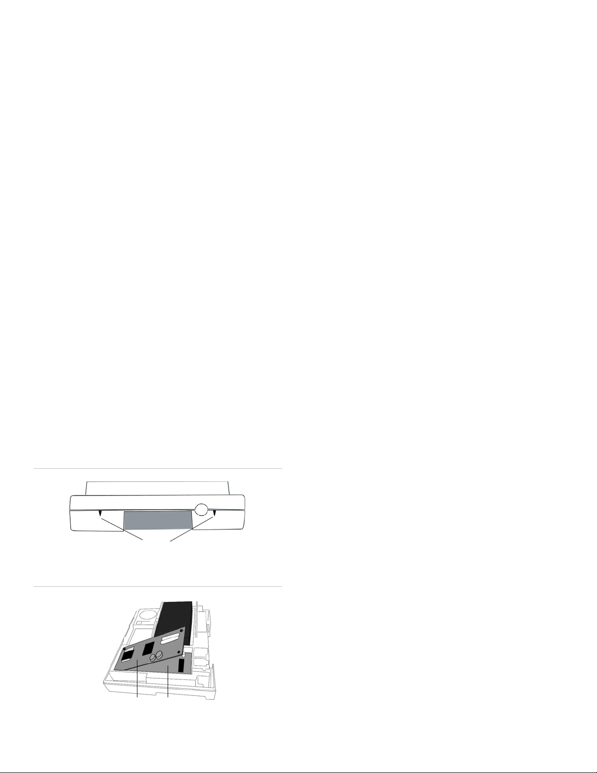
4. Insert the module by angling it down and placing the
antenna connector in the round opening (see
Figure 2 below). Make sure to angle the top of the
module
when inserting the antenna connector into
the opening so that the module is below the two
small, plastic corner tabs in the top of the module
compartment.
5. Once the module is seated evenly, carefully push
the bottom of the module into the 8-pin connector
beneath it.
6. Screw the antenna onto the module.
Make sure the antenna is screwed in completely (a
little over two turns), but do not force it. The module
must be seated correctly beneath the two small,
plastic corner tabs for the antenna to thread freely
through the round opening. If the module is above
either corner tab, the module and the antenna will
not fit correctly.
7. Pull the antenna through the back of the enclosure
and insert it inside the wall.
Power up
When a GSM module is connected to the control panel,
the panel display will show GSM Module OK for 15
seconds. If it does not display that message, check the
four LEDs at the bottom of the module. If the LEDs do
not light up at all, do a full power cycle.
To do a full power cycle:
1. Disconnect the battery leads and unplug the system
from AC power.
2. Verify that the module is inserted securely and that
the antenna is screwed in completely.
3. Connect the battery leads to the battery. Observe
polarity, red to + and black to -.
4. Place the battery inside the battery compartment
making sure to keep the wires outside the tab
holding them in place.
5. Plug the panel power transformer into the AC outlet.
It is important to connect the battery before plugging in
the AC, otherwise the panel will issue a system low
battery message regardless of the battery voltage level.
GSM phone test
To make the module connect to Alarm.com and the
GSM network the first time, you can do a GSM phone
test or initiate a panic/alarm.
To do a GSM phone test:
Figure 1: Panel tabs
1. Scroll down through the control panel menu to
System Test, and then press OK.
2. Enter the installer code (default 4 3 2 1), and then
press OK.
3. Scroll down to Comm Test, and then press OK.
Tabs
The panel displays the following GSM phone test
information:
Figure 2: Installing the module
GSM Comm Test in progress. Displays when the test
starts.
GSM Comm Test not available. Displays if the GSM
phone tests are disabled (they are enabled by default).
Top of panel
GSM Comm Test no more trials. Displays if the
allocation of ten tests has been used up. At power up,
the module starts with an allocation of ten GSM phone
tests. One test allocation will be added every 24 hours
after that to replenish the ten tests allocation. If more
Module Brass shield
2 600-1048-XT-6 Simon XT GSM Cellular Kit Installation Sheet
GSM phone tests are required, do a full power cycle.
Page 3

GSM test signal sent OK. Press Status to end.
Displays when Alarm.com has received and
acknowledged the signal. This does not guarantee that
the signal went through to a central station; it confirms
that the Alarm.com operations center received the
signal. Contact the central station directly to verify that
the signal was received on the correct account and that
the central station routing settings have been set up
correctly. The signal may not go through to the central
station if the central station account settings were
entered incorrectly on the Alarm.com dealer website, or
if Alarm.com was unable to send the signal successfully
to the central station receivers. In these cases, the panel
displays a failure to communicate message.
Control panel settings that change
Some panel settings change automatically when the
GSM module is connected to the control panel. These
settings should not be altered by the installer and
include:
Sensor/zone 40. Upon initial module power up, the
panel recognizes and learns (programs) the GSM
module as sensor/zone 40 and assigns “GSM Module”
as the sensor/zone name. Any device previously
residing in panel memory as sensor/zone 40 is
automatically deleted and must be learned
(programmed) into panel memory using an available
sensor/zone number between 01 and 39.
Clock. The GSM module sets the panel clock when it
connects to Alarm.com and then updates it every 18
hours. It is important to select the correct panel time
zone on the Alarm.com website, or the panel time will
not be accurate. If a system is powered up before the
customer account has been created, the time zone will
default to Eastern Time.
LEDs
Status LEDs indicate network and module status. The
LEDs are visible through an opening at the back of the
panel (see Figure 3 below).
Figure 3: Status LEDs
• L1 (red) = LED 1
• L2 (yellow) = LED 2
• L3 (green or yellow) = LED 3
• L4 (green or yellow) = LED 4
LED 1 error indicator. Flashes one to eight times in an
8-second interval to indicate specific error conditions.
The number of flashes indicates the error number. If
there are two or more errors at the same time, the errors
will be flashed one after the other. The LED will stay off
for at least 4 seconds between errors.
Table 1: LED 1 errors
# of
Flashes
1 The module cannot communicate with the panel. Do a
2 The SIM card is missing. The SIM cardholder can be found
3 The module is trying to register on the GSM network. This is
4 The module is registered on the GSM network, but cannot
5 The radio portion of the module is not working correctly. If
6 This is an error only if it persists for more than a minute.
7 The module being used has been programmed for a regular
8 If this error persists, the account may have been set up
Error
power cycle on the panel. If it still doesn’t work, lift the
module out of the panel and reinsert it. If that doesn’t fix the
problem, try a different module. If that doesn’t fix the
problem, try a different panel.
on the Module. Verify that the SIM cardholder is closed
securely and that there is a SIM card in the holder.
normal if it doesn’t last more than 30 seconds. If it persists
for more than a few minutes, the module is having problems
registering with the GSM network. Check LED 4 for signal
level. If the signal level is too low, change the panel’s
location or use a remote antenna option. If the signal is
good, the module may be roaming on a GSM network that
doesn’t partner with our GSM providers, or the SIM card
was not activated yet because the Alarm.com account was
not created correctly. If the module had been
communicating in the past, there may be new RF
interference from some other device or building.
connect with Alarm.com. Contact Alarm.com technical
support at 866.834.0470.
this persists for more than a few minutes, the module may
need to be replaced. This error is extremely rare so verify
that the module is flashing 5 times.
Otherwise, it is just an indication that the module is fixing an
unusual condition regarding communication with the GSM
network.
Simon panel (not Simon XT). Please label the module
appropriately and swap it with a different Simon XT module.
incorrectly. Contact Alarm.com technical support at
866.834.0470. You will be asked t check the serial number
of the module.
LED 2 panel communication. Flashes with every
communication between the module and the panel. The
L2 L3 L4
L1
600-1048-XT-6 Simon XT GSM Cellular Kit Installation Sheet 3
pattern is a series of quick flashes every 2 seconds in
idle mode or every 4 seconds in power save mode.
Page 4

LED 3 GSM communication. Flashes with every
communication between the module and its radio unit in
idle mode, and with every communication with
Alarm.com in connected mode. In power save mode, this
LED flashes in unison with LED 2.
LED 4 GSM signal level. Flashes up to five times to
indicate signal strength, or toggles on/off when
communicating with Alarm.com servers. The number of
bars may not correspond to the bars shown on your cell
phone. A level of five bars is obtained only in the
strongest signal conditions.
Signal level is updated every 10 seconds if it fluctuates,
or every 30 seconds if it is stable. If LED 4 is not flashing
it indicates one of the following:
• The module is in power save mode.
• The module is just powering up.
• There is no GSM coverage in the area.
We recommend a signal level of two or higher for proper
operation of the module.
• LED 2 indicates communication with panel.
• LED 3 indicates communication with Alarm.com.
• LED 4 alternates 2 seconds on, then 2 seconds off.
Sleep mode. The panel is not connected to AC power,
or there is an AC power failure and the battery level is
low. The module will connect to Alarm.com to send a
signal, but otherwise is in a state that draws no power.
LED 2 and LED 3 may occasionally flash in sleep mode.
Special key presses
Press any of the following panel keys for 10 seconds or
more and the related information will display on the
panel. Most messages display for less than 30 seconds,
but can be cut short by pressing the # key for 10
seconds.
1 key. Displays the 10-digit module serial number. This
number is needed to create the Alarm.com customer
account.
2 key. Displays the module firmware version.
Module modes
The module modes (states) include:
Idle mode. AC power is okay and the module is not
currently talking to Alarm.com servers.
• LED 1 flashes errors, if any.
• LED 2 indicates communication with panel.
• LED 3 indicates communication with radio unit.
• LED 4 indicates the signal level (0 to 5 bars).
Power save mode. The module just powered up, or AC
power is down, or AC power was recently restored and
the battery is charging. The module draws 10 mA while
in power save mode. It is fully functional and will go into
connected mode as soon as a signal needs to be sent.
Pressing the 5 key for 10 seconds or more will switch the
module into idle mode and update the signal level
reading. The system will go into idle mode every 2 hours
to check for any incoming messages.
• LED 1 is inactive.
• LED 2 indicates communication with panel.
• LED 3 flashes in unison with LED 2.
• LED 4 is inactive.
Connected mode. The module is currently talking to
Alarm.com servers. The module stays in connected
mode for at least 4 minutes after reporting an event to
Alarm.com, unless the 5 key is pressed for 10 seconds
or more, which will cause the module to go back to idle
mode.
3 key. Displays the 15-digit SIM card number. You may
be asked for this number by a technical support
representative to verify that the module was activated on
the GSM network.
4 key. Displays a list of report types that the module will
send to Alarm.com and to the central station.
5 key. Displays the wireless signal strength level and
module status or error, if any. This key is also used to
force the module to read the signal strength.
6 key. Displays the battery voltage as read by the
module to two decimal places, and the AC power status.
8 key. Displays the GSM frequency at which the radio is
currently connected. “High” equals 1900 MHz, and “Low”
equals 850 MHz.
Report types (4 key)
Press the 4 key for 10 se
conds or more to get a list of
the types of events that will be reported by the module.
These types will be displayed on the keypad. Reports
can be turned on or off via the Alarm.com dealer website
and may depend on the customer service plan.
Table 2 on page 5 describes the reporting codes from
the 4 key. Co
des not included in the table are for
Alarm.com internal use only.
• LED 1 flashes errors, if any.
4 600-1048-XT-6 Simon XT GSM Cellular Kit Installation Sheet
Page 5

Table 2
: Reporting codes
Code Description Code Description
Tst Phone test Pgm Panel
Ala Alarms Tpr Tamper
Sys System troubles Can Cancels
Zon Sensor troubles Nor Normal activity
Arm Arm/disarm Pow Modem online
Byp Sensor bypass Png Pings
Ac AC power failure C&S Smash and crash
Pho Phone failure Bat Panel low battery
programming
Note: Certain report types are not included with all
Alarm.com service plans. Contact Alarm.com for more
information.
GSM status and signal level (5 key)
Press the 5 key for 10 se
conds or more to get the signal
level and the module status or error, if any. The panel
will display bars for the signal level (0 to 5) and a
number (2 to 31) followed by the current mode.
Table 3 below describes the module status indications.
Improving wireless signal strength
For optimal wireless signal strength, follow these
guidelines:
• Install the module above ground level, as high up as
possible within the structure.
• Install the module near or adjacent to an outside-facing
wall of the structure.
• Do not install the module inside a metal structure or close
to large metal objects or ducts.
• Make sure to follow the antenna positioning guidelines that
are included with the antenna. Certain antennas must be
oriented in a specific way in order to receive signals.
• Upgrade the antenna. If you are using the ¼ wave
antenna included with the GSM gateway module, upgrade
to a remote cable antenna. Contact Alarm.com technical
support at 866.834.0470 for antenna options.
As you make changes to the module location or antenna
to improve strength, you can press and hold the 5 key on
the panel keypad to get an updated signal strength
reading on the display.
Table 3: Module status
Status Description
Idle Most common state.
Roaming Roaming on partner network.
SIM missing Same as 2 flashes on LED 1.
Power save mode AC power is down.
Registering Same as 3 flashes on LED 1.
Connection error Same as 4 flashes on LED 1.
Radio error Radio is not operating correctly, same as 5
flashes on LED 1.
Server error Same as 8 flashes on LED 1.
Connected Currently talking to Alarm.com servers.
Connecting… In the process of connecting to Alarm.com.
Updating… Updating signal level.
Pressing the 5 key for 10 seconds while the module is in
power save mode or is connected to Alarm.com (but not
actively transmitting), will allow the module to refresh its
signal level reading. This can be useful during panel
installation while looking for the best location, and when
the module is likely to go in power save mode because
the transformer is unplugged, or because it is connected
to Alarm.com when it cannot get a signal level reading.
Troubleshooting
• The LEDs are not responding.
Turn off the panel power and verify that the module
is correctly inserted into the panel.
• The module status LEDs do not turn on immediately after
initial power up.
You may need to wait a few minutes after powering
up for the module to register on the network.
• Panel/sirens are beeping even though the system is not
armed.
Press the touchpad status button and the panel
reports the trouble condition. Consult the panel
documentation for details.
Note: If the GSM module is powered down for a short
time, it may receive buffered messages from Alarm.com
when module power is restored.
• The panel will not do a GSM phone test.
Only 10 GSM phone tests are allowed in a 24-hour
period. If more GSM phone tests are required,
power cycle the control panel.
600-1048-XT-6 Simon XT GSM Cellular Kit Installation Sheet 5
Page 6

New user web setup
Regulatory information
This section describes how to help your customers set
up their website account, and only applies to
web/interactive customers. You can skip this section if
your customers are using Alarm.com for wireless
signaling only.
Before a customer can configure their website account,
the Alarm.com account for that customer must be
created on the dealer website, and the GSM module
associated with the account must be installed
successfully.
To log on and access the New User Setup Wizard, go to
www.alarm.com (or custom dealer website address) to
complete the new subscriber setup procedure.
Customers will need the following:
• The website login and temporary password included on
the Alarm.com welcome letter generated when the
account was created by the dealer.
• A list of their service sensors and touchpads with
corresponding IDs.
• At least one phone number and email address where
notifications can be sent.
Note: If not all sensors and touchpads were learned
(programmed) in before powering up the module, an
updated sensor list must be requested by sending a
command from the dealer site under Support Options >
Sensor List.
At least one sensor must be learned (programmed) into
the panel to complete the new subscriber setup.
Specifications
Compatibility Simon XT panels with software versions
0.0.H and later
Voltage 6 V nominal (operating range 5.1 to 12 VDC)
Standby current 30 mA (10 mA in power save mode)
Peak current 1.7 A
Cellular network Quad-band GSM/GPRS
Dimensions (H × W) 4-1/16 × 1-7/8 in.
Operating temperature 32 to 120ºF (0 to 49ºC)
Storage temperature -30 to 140ºF (-34 to 60ºC)
Relative humidity 90% noncondensing max.
Listings FCC Part 15, PTCRB, Cingular
FCC
This device complies with part 15 of the FCC rules for
Class A devices. Operation is subject to the following
conditions.
1. This device may not cause harmful interference.
2. This device must accept any interference
received, including interference that may cause
undesired operation.
Changes or modifications not expressly approved by the
party responsible for compliance could void the user’s
authority to operate the equipment.
In accordance with FCC requirements of human
exposure to radiofrequency fields, the radiating element
shall be installed such that a minimum separation
distance of 20 cm is maintained from the general
population.
FCC ID: MIVGSM0308
IC: 4160A-GSM0308
ETL
A representative sample of this product was evaluated
and found to comply with the applicable requirements of
the standards for:
• Household Fire Warning Systems Units, ANSI/UL 985, 5th
Ed rev 04/04
• Household Burglar-Alarm System Units, ANSI/UL 1023,
th
Ed rev 12/04
6
• Digital Alarm Communicator System Units, ANSI/UL 1635,
rd
Ed rev 12/04
3
• Residential Fire Warning System Control Units, ULCS545, 2
• Household Burglar Alarm System Units, ULC Subject
C1023, 1
nd
Ed dated 07/02
st
Ed dated 01/74
Contact information
For contact information, see www.utcfireandsecurity.com
or www.interlogix.com.
Copyright © 2011 UTC Fire & Security. All rights
reserved.
6 600-1048-XT-6 Simon XT GSM Cellular Kit Installation Sheet
 Loading...