

Page 1
Page 2
STANDBY GENERATOR SETS V-6.4
1
1. WELCOME............................................................................................................................................3
2. BASIC SAFETY RULES ......................................................................................................4
3. DESCRIPTION OF GENERATOR SET............................................................................................... 6
3.1. SOUND INSULATION.............................................................................................................. 11
3.2. CONTROL PANEL .................................................................................................................... 12
3.3. ELECTRICAL CONFIGURATION...........................................................................................15
3.4. RETENTION BATH...................................................................................................................16
4. INSTALLATION OF THE GENERATOR SET ................................................................................. 17
4.1. UNLOADING AND TRANSPORT........................................................................................... 17
4.2. INTALLATION PRINCIPLES...................................................................................................18
4.2.1. Premises........................................................................................................................... 18
4.2.2. Ventilation and cooling.................................................................................................... 19
4.2.3. Fuel .................................................................................................................................. 19
4.2.4. Automatic fuel transfer system........................................................................................ 19
4.2.5. Exhaust ............................................................................................................................ 20
4.2.6. Generator set startup ........................................................................................................21
4.2.7. Electrical connection .......................................................................................... 22
4.2.7.1. Safety instructions............................................................................................... 22
4.2.7.2. Installation of CONTROL section : ......................................................... 27
4.2.7.3. Installation of ELECTRICAL POWER section: .................................................. 28
4.2.7.4. Earthing:............................................................................................................. 30
4.2.7.5. Motorized changeover switches:.........................................................................30
4.3. STORAGE .................................................................................................................................. 30
5. STARTUP ............................................................................................................................................ 31
5.1. POWER FACTOR AND GENERATOR SETS ......................................................................... 32
5.2. LIGH LOAD OPERATION ON DIESEL ENGINES ................................................................ 32
Page 3

STANDBY GENERATOR SETS V-6.4
2
6. OPERATION MANUAL.....................................................................................................................33
6.1. CONTROL PANEL COMPONENTS ........................................................................................33
6.1.1. Deep sea 4420 digital control module..............................................................................35
6.1.2. DEEP SEA 7310/7320 Digital Control Module ..............................................................39
6.1.3. INTELIGENNTDigital Control Module ..........................................................................50
7. MAINTENANCE OF GENERATOR SET.......................................................................................... 56
7.1. PRIOR TO MAINTENANCE..................................................................................................... 56
7.2. DURING MAINTENANCE .......................................................................................................56
7.3. MAINTENANCE CHART .........................................................................................................60
8. TROUBLESHOOTING .......................................................................................................................61
9. PROTECTION FROM THE ENVIRONMENT ..................................................................................62
10.WARRANTY .......................................................................................................................................62
11.NOISE LEVEL..................................................................................................................................... 63
12.DECLARATION OF CONFORMITY ..................................................................................... 63
13.APPENDIX 1: FIGURES.....................................................................................................................64
14.APPENDIX 2: IMAGE INDEX...........................................................................................................66
15.APPENDIX 3: PRE-DELIVERY INSPECTION DOCUMENT......................................................... 67
16.APPENDIX 4: DERATING OF ENGINE POWER RATING: ...........................................................68
Page 4

STANDBY GENERATOR SETS V-6.4
3
1. WELCOME
Thank you for choosing a GRUPOS
ELECTRÓGENOS EUROPA S.A.generator set.
The purpose of this manual is to familiarize the
user on how to use and work with the electrical
generator, its components and maintenance.
We recommend a carefully reading this
document prior to working with the equipment to
ensure its correct use.
Save this manual for future reference and if the
generator set is resold be sure to include the
manual along with the unit.
The following is a general description of the unit
and the information necessary for installation,
operation and preventive maintenance.
Additionally, you should have received a
specific user manual for the Engine and
Alternator, electrical setup, a set of keys, ATS
(upon order), silencer or exhaust tube and
flexible tube (supplied separately for open-skid
units).
Should you have any problem with the
equipment provided, please contact the
distributor directly.
GRUPOS ELECTRÓGENOS EUROPA S.A.,
in a constant effort towards product
improvement, shall revise its manuals and
include improvements made to the supplied
units. Thus the information contained in this
document is subject to change without prior
notice and without obligation to update.
Page 5

STANDBY GENERATOR SETS V-6.4
4
2. BASIC SAFETY RULES
Safety precautions and recommendations for handling the Electrical Generator supplied by GRUPOS
ELECTRÓGENOS EUROPA S.A.
1) Do not allow the unit to be used by non-authorized personnel or minors not accompanied by an adult.
2) Use the necessary individual protection equipment.
3) Ground the machine and ATS panel.
4) Make sure there is sufficient lighting on the genset and on the control panels before start-up; the
minimum lightning level should be 20 lux.
5) Do not install the open-skid electrical generator outdoors: risk of electrocution and non-functioning.
6) The connection should be made by a qualified electrician in accordance with current norms and
regulations. An incorrectly made connection can cause electrical feedback with electrocution hazards
for anyone working with the mains power supply. The mains connection should always be made using
an automatic transfer switch (ATS); if none has been supplied, contact your distributor or GRUPOS
ELECTRÓGENOS EUROPA S.A.
7) The supply line between the generator set and the consumers should be protected by means of a
differential relay for protection against earth leakage.
8) The electrical installation between the generator unit and ATS should be protected using
electromagnetic circuit breaker for protection against short circuits and overcurrents. The circuit breaker
is supplied optionally by GRUPOS ELECTRÓGENOS EUROPA S.A.
9) Do not operate the unit with the doors open: risk of electrocution, burns or entrapment. Be sure the
doors are closed with keys before the start-up.
10) The exhaust system generates enough heat to ignite some materials. Therefore, never install the
generator set near flammable materials or near materials that may ignite easily or in locations where the
risk of a fire occurring is high.
11) The gases generated by the set’s engine are highly toxic and may result in death. Never inhale the
exhaust gases generated by the set. If the unit must be operated in an enclosed area or in a poorly
ventilated area, the engine exhaust gases must be routed towards the exterior for a safe operation.
12) Do not touch the engine or the exhaust during operation of the generator set: Severe burns may occur.
The exhaust hot areas are protected against accidental contact. In areas where this type of protection is
not feasible, the risk is indicated using appropriate signs.
13) Ensure proper ventilation in the area where the generator is installed in order to guarantee sufficient
flow of cooling air.
Page 6

STANDBY GENERATOR SETS V-6.4
5
14) Know how to stop the unit in case of emergency. Be special careful with his handling and storage.
15) For refueling the engine, the generator set incorporates an exterior fuel filler neck and cap for filling the
tank with diesel. Never refuel with the engine running or in poorly ventilated areas; remember that fuel
vapors are toxic and flammable. Take the necessary safety precautions when handling fuel; the use of
gloves and safety goggles is recommended.
16) The fuel used is flammable, volatile and toxic. Prevent any spill and carefully wash your hands after
handling.
17) If you notice abnormal behavior by the generator set, stop the unit, and then locate, examine and resolve
the potential failure of the unit prior to restarting. Contact our technical services department if needed.
18) Keep the unit at least one meter away from buildings or other units.
19) Be cautious when switching or installing batteries as they contain acids which are highly hazardous.
Avoid spills and use protection to avoid contact with the skin and eyes. In case of accidental contact,
rinse thoroughly with water and contact a doctor service immediately.
20) In case of ingestion of battery acid, drink large amounts of water and milk and contact a doctor
immediately.
21) Use only distilled water in the battery, the tap water
22) If a battery is filled above the maximum level, the electrolytes will spill out; if this happens, clean the
area quickly to avoid corrosion of the parts it has come in contact with.
23) Frequently clean the unit to avoid obstructions or the entry of foreign elements into the unit (dust,
moisture, etc.).
24) Regularly inspect the unit’s electrical cables.
25) Engine oil is toxic and hazardous to the environment. Adopt the necessary safety measures when
handling engine oil. Prolonged exposure to used engine oil may cause skin cancer. Carefully wash your
hands after handling.
26) Avoid oil spills on both the inside and outside of the generator. In case of oil spill on the inside of the
unit, clean it properly as it could potentially become a flammable material.
27) Do not overfill the tank and make sure it is closed properly after filling. Use extreme precaution if fuel
is spilled: the vapors and the fuel itself are flammable. Clean the area completely before starting up the
unit.
28) Do not smoke or bring any flames or sparks in the vicinity of the electrical generator: risk of explosions.
Page 7
STANDBY GENERATOR SETS V-6.4
6
3. DESCRIPTION OF GENERATOR SET
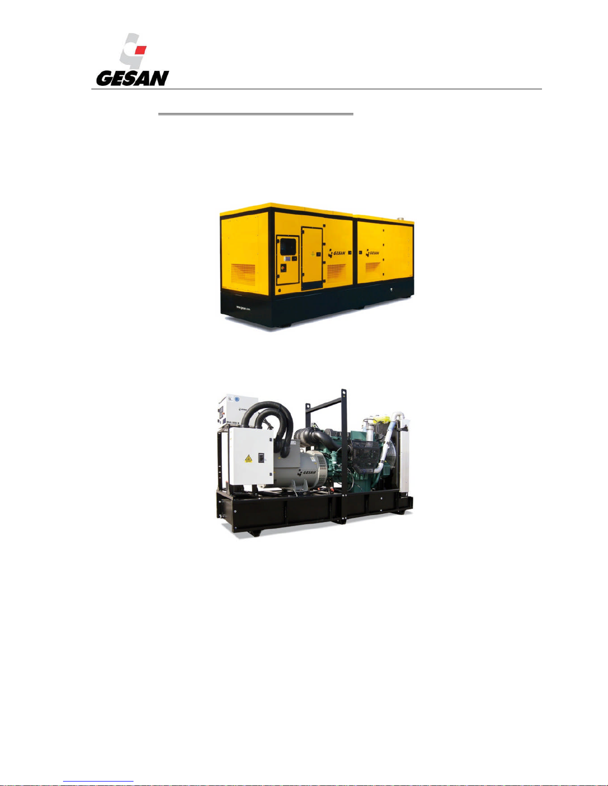
Following you have general overview of the generator set (doesn´t match with the delivered genset) and
its different configurations manufactured by GRUPOS ELECTRÓGENOS EUROPA S.A.
Image 1- Generator set with sound proof canopy.
Image 2- Generator set without canopy
Page 8
STANDBY GENERATOR SETS V-6.4
7
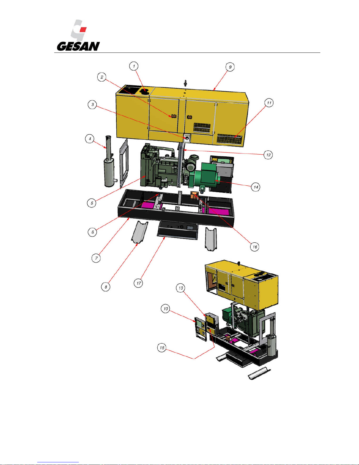
Image 3- Detailed view of Insonorized genset
Page 9

STANDBY GENERATOR SETS V-6.4
8
1) Coolant tank hatch
2) Side access door
3) Fuel tank cap
4) Exhaust silencer
5) Engine
6) Shock absorbers
7) Base frame
8) Base support
9) Canopy
10) Electrical Panel Doors
11) Ventilation grill
12) Lifting frame and eyebolt
13) Control panel
14) Alternator
15) Electrical power panel
16) Battery
17) Fuel tank
Page 10
STANDBY GENERATOR SETS V-6.4
9
Image 4- Detailed view of openskid genset
Page 11

STANDBY GENERATOR SETS V-6.4
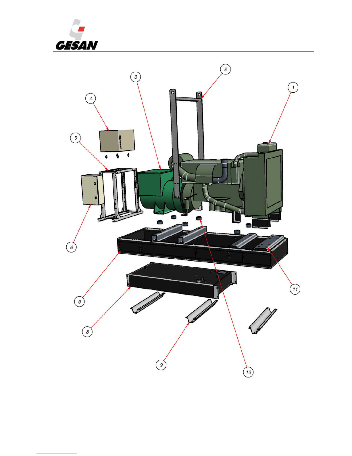
10
1) Lifting frame
2) Engine
3) Shock absorbers
4) Base frame
5)
Fuel tank
6) Base support
7) Control panel
8) Electrical power panel (optional)
9) Alternator
10) Battery
Page 12
STANDBY GENERATOR SETS V-6.4
11
3.1. SOUND INSULATION
The supplied unit may be:
Soundproofed. Includes sound-insulating canopy.
Over base support Open skid. You must keep in mind that in compliance with current
regulations may require that proper room sound insulation will be provided for this model. (See
4.2 INSTALLATION)
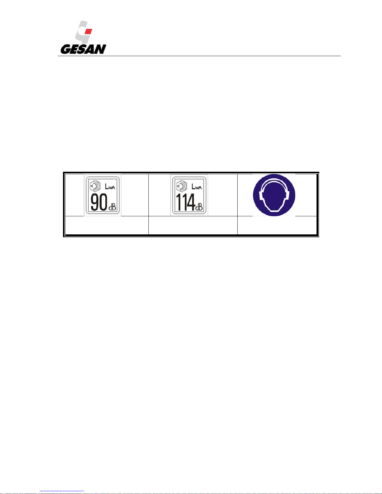
Each Electrical Generator is provided with a sticker indicating the level of noise output produced and the
need to use hearing protection.
Noise output 90 dBA Noise output 114 dBA
Use of hearing
protection required.
Image 5- Noise output pictograms and hearing protection required
The noise level has been measured according to the European directive 2000/14/EC and in compliance
with the maximum levels established by directive 2005/88/EC.
Please consider the local and national regulations that could be more restrictive. In any case, it’s the
installer and owner responsibility to comply with the current legislation
Page 13
STANDBY GENERATOR SETS V-6.4
12
3.2. CONTROL PANEL
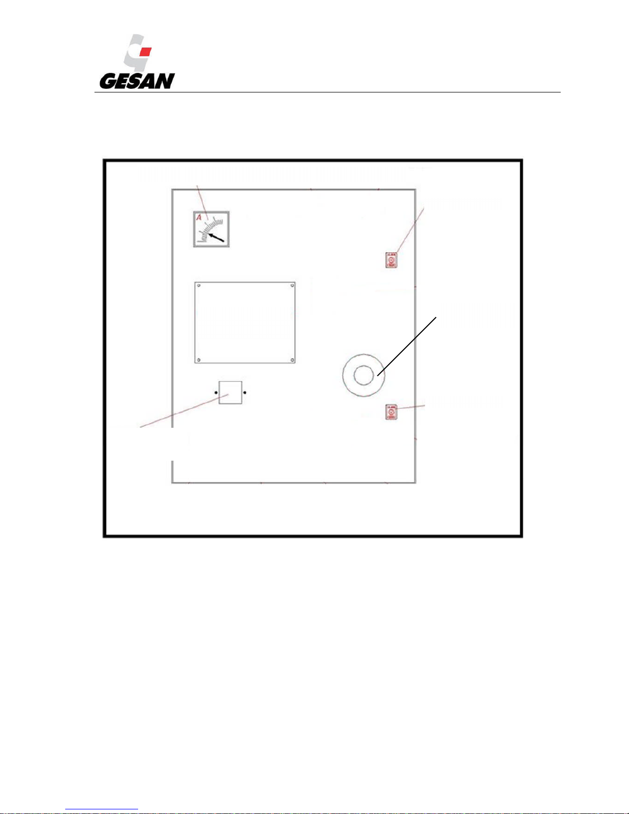
The unit provided may be controlled by different modules depending on the type of function it has been
designed to perform.
Image 6- Generic Control Panel
1-3 →.Electrical Gauges
4→ Hour meter
5→ Earth leakage relay (It may be
installed inside the electrical panel)
6→ Indication lamps (green, red, yellow)
7→ Mode Switch
8→ Engine Gauges
AMMETER (OPTIONAL IN DEEP SEA 4420 CONTROL PANNEL)
LOCK
LOCK
DIFFERENTIAL
(OPTIONAL)
AUTOMATIC
CONTROL UNIT
EMERGENCY
BUTTON
Page 14
STANDBY GENERATOR SETS V-6.4
13
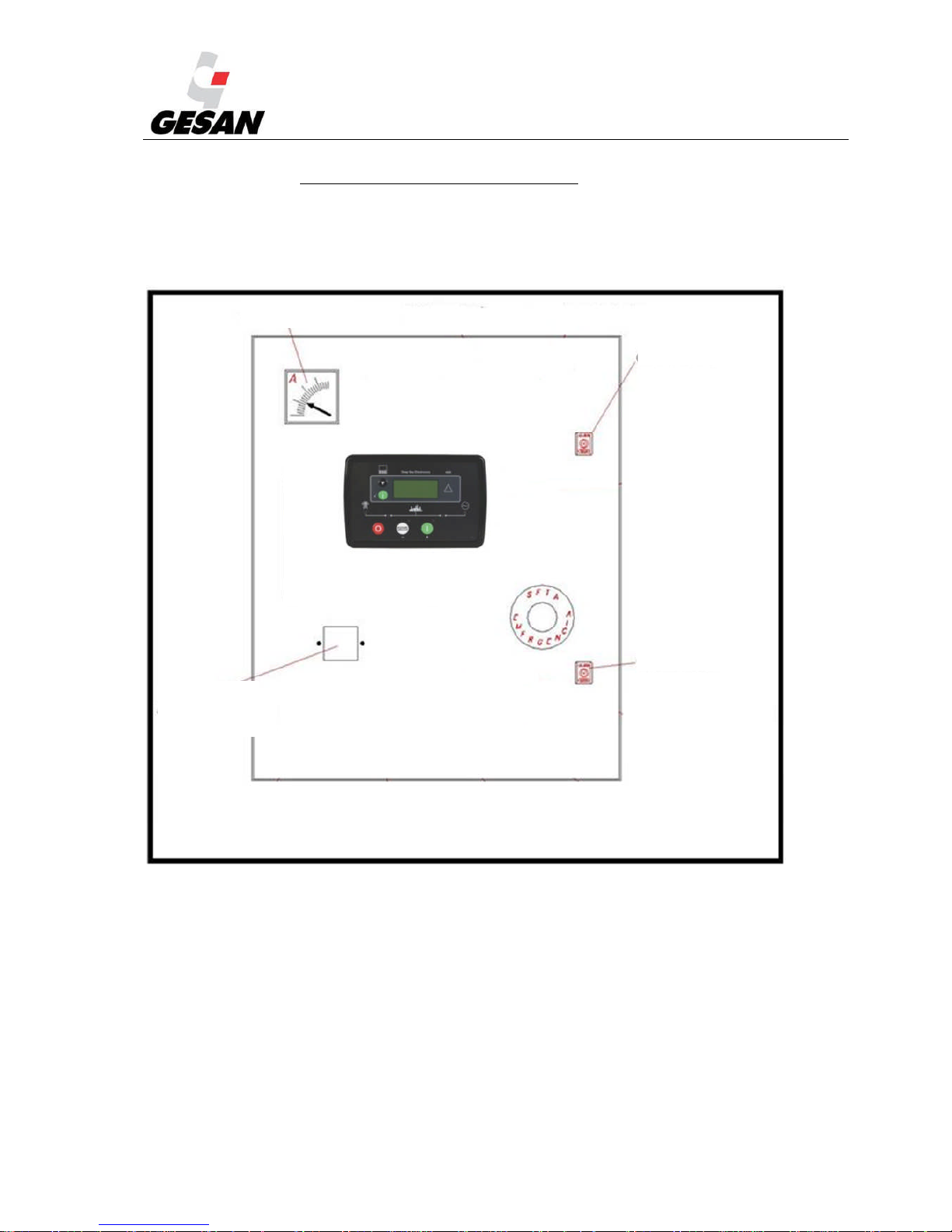
3.2.1. INTELIGENNTDIGITAL CONTROL PANNEL
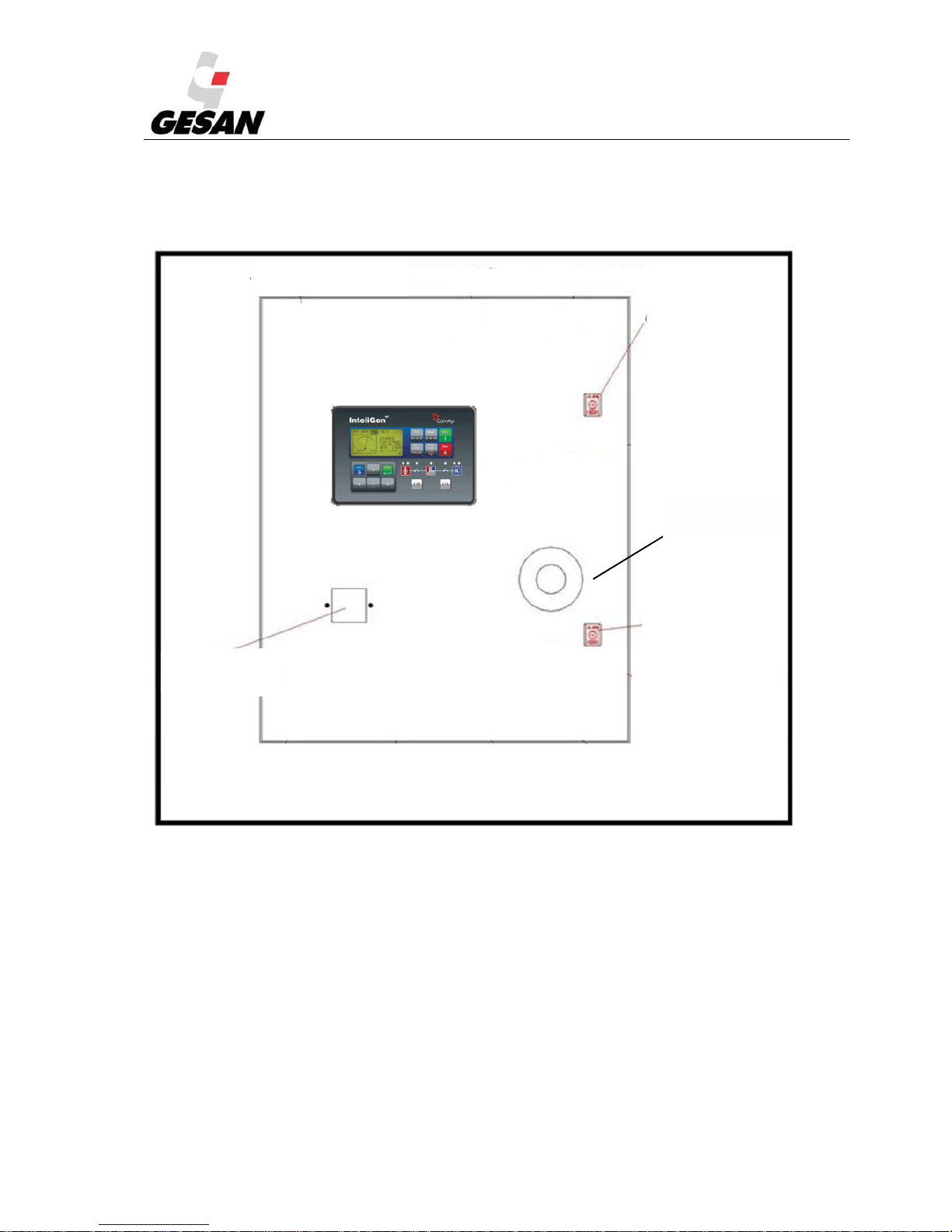
I you have adquire a genset with INTELIGEN control panel; the electrical box will have an appearance as
shown in the figure below:
Image 7-Control panel with InteliGen
N T
module
LOCK
DIFRERENTIAL
(OPCIONAL)
LOCK
EMERGENCY
BUTTON
Page 15
STANDBY GENERATOR SETS V-6.4
14
3.2.2. PLACA DIGITAL DE CONTROL DEEP SEA
I you have acquire a genset with INTELIGEN control panel; the electrical box will have an
appearance as shown in the figure below:
Image 8-Control panel with DEEP SEA Control module
DIFERENCIAL
(OPCIONAL)
CERRADURA
CERRADURA
AM
METER
Page 16
STANDBY GENERATOR SETS V-6.4
15
3.3. ELECTRICAL CONFIGURATION
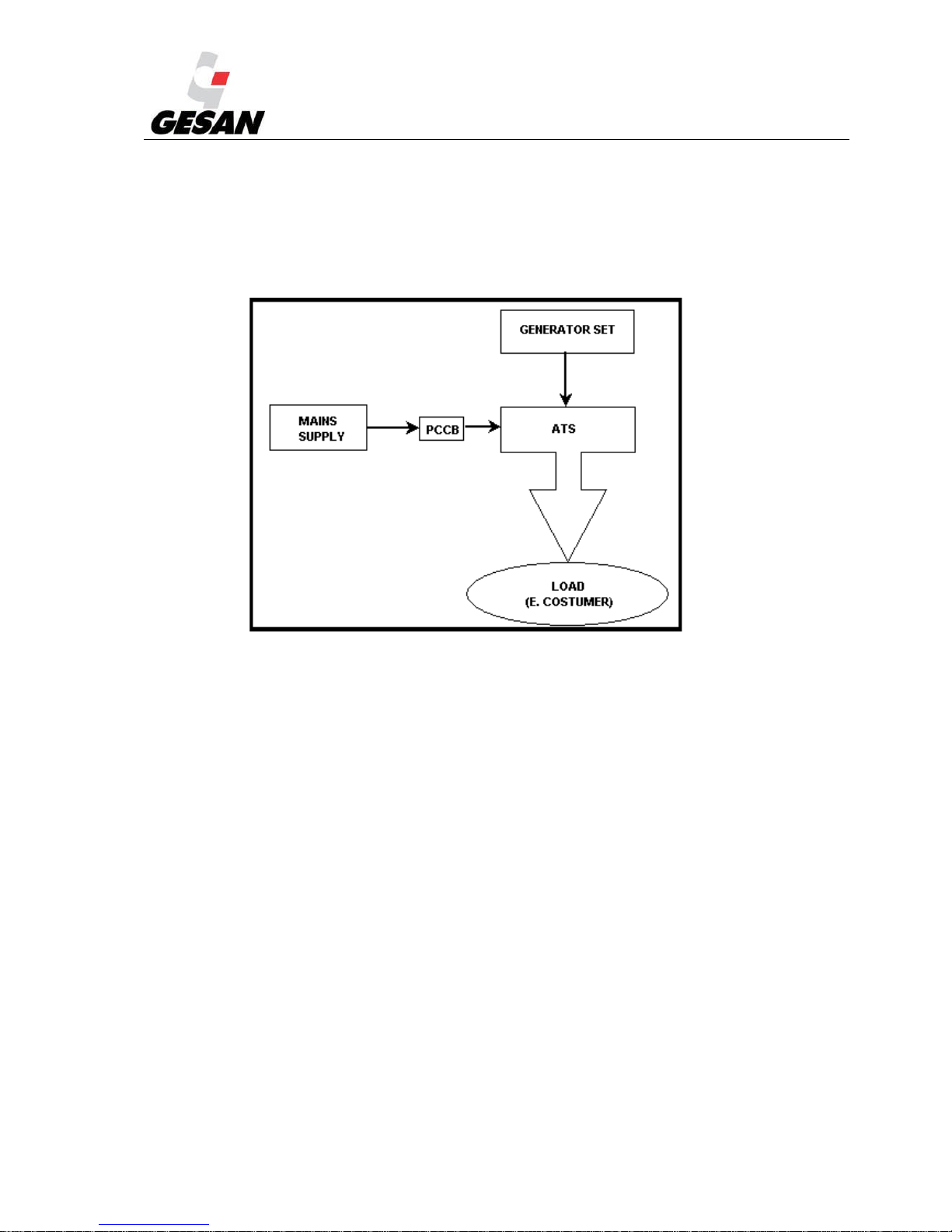
The supplied unit may be one of three types:
The generator unit is supplied with automatic transfer switch (ATS).
The generator unit is supplied without ATS. Note that its installation is required.
Image 9- Load Transfer diagram
Note: PCCB = Power Control Circuit Breaker
ATS may be with contactors, motorized changeover switch or motorized circuit breakers
The genset is supplied as “Standby by signal” without ATS. The Electrical Generator
stands idle until it receives a signal from an autonomous external system which monitors the mains
and controls the automatic transfer switch for startup.
Page 17

STANDBY GENERATOR SETS V-6.4
16
3.4. RETENTION BATH
The generator set may include a built-in retention bath to prevent spills from the unit—such as fuel, oil or
coolant—with a capacity of 110% with respect to the total volume of liquids.
It is the responsibility of the installer and the owner to take the appropriate measures to avoid
contaminants spillage, in case your genset doesn´t includes retention bund and consider that it should have
it, please contact with our technical service.
Image 10- Retention Bath
1) 4 drain plugs, 2 on each side of the pan
2) Slots for inserting forklift arms
3) Retention bath level senders (optional)
221
1
3
Page 18
STANDBY GENERATOR SETS V-6.4
17
4. INSTALLATION OF THE GENERATOR SET
In this part of the manual it is described how to install a “generic” generator set composed of a diesel
engine, alternator and electrical panel supplied by GRUPOS ELECTROGENOS EUROPA S.A. For other
applications, our technical service will advise.
4.1. UNLOADING AND TRANSPORT
Uploading and transport must be performed by qualified personal, taking into account minimal security
conditions.
The floor must be capable of supporting the full weight of the Generator and the forklift.
Make sure that the battery is disconnected.
Make sure that the fuel tank is empty.
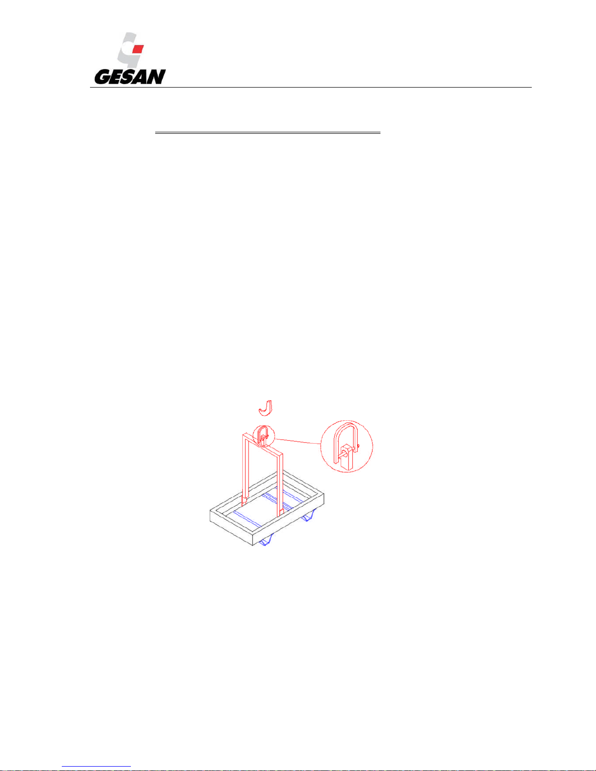
Place the arms of the forklift below the chassis at an equal distance with respect to the
lifting frame.
With a hoist, raise the unit using the lifting frame eyebolt.
The image below shows a drawing of a generator unit which includes a frame with a single lifting point.
Image 11- Lifting frame
Page 19
STANDBY GENERATOR SETS V-6.4
18
4.2. INTALLATION PRINCIPLES
4.2.1. Premises
The following considerations must be kept in mind: the fuel supply, ventilation of the premises, the
output and direction of the exhaust gases and the noise produced.
Dimensions
The dimensions should allow for the various required maintenance or disassembly operations. A
minimum of one meter should be left on all sides of the generator to allow for the doors to be opened.
Openings
The premises should have an entrance that is large enough for the generator to pass through and openings
large enough for ventilation (fresh-air intake and radiator hot air outlet), with the appropriate surface area
based on the generator’s output, the premises’ cooling system and the soundproofing system used.
GRUPOS ELECTRÓGENOS EUROPA S.A. does not recommend installing canopied units in closed
spaces.
If the unit must be installed in an enclosed space, it is recommended to use an open-skid model and
soundproof the work area, in keeping with the current fire-prevention regulations.
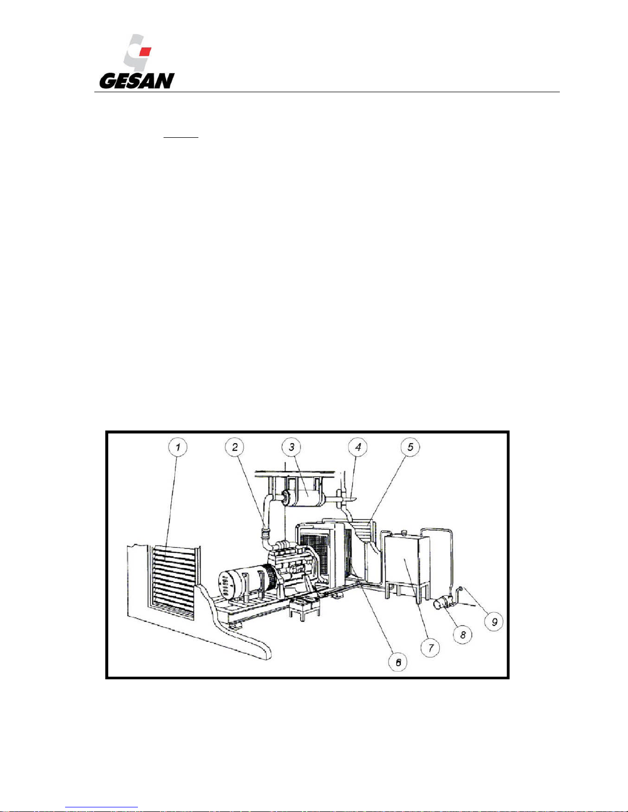
The following image shows a typical installation of an open-skid unit in a closed space.
Image 12- Detailed view of installation of an open-skid unit
Page 20
STANDBY GENERATOR SETS V-6.4
19
1) Air intake grill. Will be at least 1.4 times the surface area of the engine’s radiator panel.
2) Smoke exhaust line. This will be explained in more detail later.
3) Silencer. Must be firmly installed and fastened to a stable structure.
4) Smoke exhaust outlet. Smoke must flow out through a point which impedes its re-entry into the
space where the working unit is installed.
5) Radiator air outlet grill. Will be at least 1.25 times the surface area of the engine’s radiator panel.
6) Cooling air channel. Prevents re-entry of hot air into the space where the unit is installed.
7) Optional external fuel tank (optional).
4.2.2. Ventilation and cooling
The heat produced by the generator’s thermal engine must be evacuated from the premises.
The heat is generated by the cooling of the cylinders, the radiation from the engine block, the exhaust pipe, the
cooling of the alternator and the radiator air output.
Insufficient ventilation could produce an increase in the ambient temperature of the premises and cause the
generator to lose engine power until finish in a shut down.
4.2.3. Fuel
In keeping with current regulations, special attention should be paid to the storage of fuel, which is classified
as a hazardous product. The installation of the generator will include a day tank and an optional external fuel
storage tank.
Depending on the output of the generator, the fuel tank may be external instead of being built into the base
frame. This tank should be installed within a maximum distance according to the engine fuel pump suction
capability (see the Engine manufacturer’s manual). The installation will be carried out according to current
regulations.
4.2.4. Automatic fuel transfer system
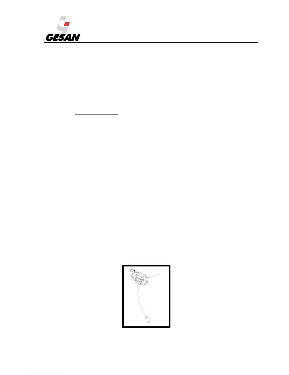
The unit may include a self-suction, eccentric fuel transfer pump (SAB-BE) for the transfer of the fuel from an
external fuel tank to the internal one. This pump will self-prime with self-adjusting blades. Includes a recirculation
bypass valve. The pump has an internal removable filter, which must be used.
Image 13- SAB-BE Pump
Page 21
STANDBY GENERATOR SETS V-6.4
20
To install the pump, consult the manual supplied by the client.
Note: If unit is positioned beyond the recommended distance, pump should be dismounted and placed near external tank Pump will
function if the unit is running; it has an OFF/AUTO switch located on the door of the unit’s electrical panel.
4.2.5. Exhaust
In the exhaust installation, pressure drop, insulation, suspension and sound levels should all be taken into
account.
The compensators and flexible pipes used in the installation will absorb the displacement of the unit (due to
dilations and vibrations).
The units supplied by GRUPOS ELECTRÓGENOS EUROPA S.A., depends on the model, may or may not
include a rain cap. The units are equipped with two holes on the underside to prevent internal water
accumulation.
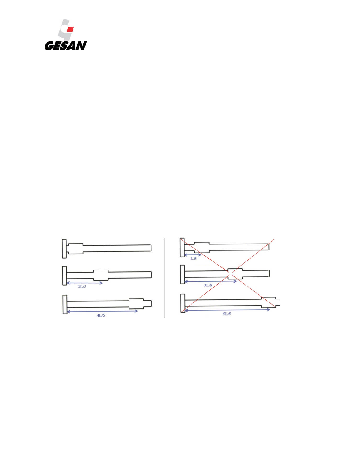
The optimum muffler locations are, first, directly behind the exhaust manifold, and secondly at 2/5 or 4/5 of
the total exhaust system length. The reason for this is the existing standing waves, especially for long exhaust
systems, when the natural pipe frequency is in resonance with the fundamental engine frequency or one of its
harmonics. The worst muffler locations in order of valve are 1/3, 3/5 or at the end of the system.
The best muffler locations in order of values are The worst muffler locations in order of value are
L = total exhaust system length (elbows may be considered as straight portions).
Note: In installations where it is required, the exhaust pipe diameter must be increased. If the installation
isn´t correct, seriously engine damage can be caused.
In some models, the silencer is exactly symmetric, in this case, manufacturers often marks the exhaust
side with an “S” mark.
Page 22

STANDBY GENERATOR SETS V-6.4
21
4.2.6. Generator set startup
The startup system used by the generator set is electrical and consists of a 12 or 24 V electric engines
powered by one or more batteries, usually lead.
Low temperatures make engine cranking difficult. Start-up failure (three attempts without success) entails
the stopping of the motor and, as a result, of the entire generator unit. In order to avoid it, and to ensure
correct start up of the generator set at any external temperature, heating of the entire unit is made (heating
of coolant water) by means of a boiler powered by mains. This system will work automatically, by a
thermostat (setup in factory from 40 to 60ºC) and it will be correctly indicated on the control panel by a
lamp.
If the genset is supplied outside Spain, the batteries will be supplied charged.
The placement into service of the this batteries should be done by removing the vent caps and filling each
cell using sulphuric acid with a density of 1.28 (or 1.23 in tropical countries). Let it sit for at least 20
minutes and check the electrolyte level (25 mm above the plates; never fill to the brim). Finally put the caps
back on.
It is recommended that protective eyewear and gloves be worn when adding battery acid. Make sure that there is nearby
access to tap water in order to wash any areas that come into contact with the acid.
Caution should be performed indicated in this Manual. (Be especially careful with potential short circuits that could occur
when coming in contact with the unit’s metallic objects).
In the case that an MTU engine has been purchased, when a shutdown occurs due to continuous
operation, the central unit uses a large amount of battery power, which may cause the battery to run out and
not be able to restart the engine; therefore, a selector is available in the control panel, which allows
disconnecting the battery in the case of a prolonged stoppage. For this purpose, we advise you carry out the
following start-up process:
1) Place the switch in position 1.
2) Start the generator set.
3) Place the switch in position 0.
Note: Step 1 is strongly recommended, as if the selector is in position 0 once the generator set is running, the board will
remain without a power supply.
It is recommended that the central unit not be set to position 1 for more than 2 days since the battery would completely
discharge, which would not allow restarting the set.
If your generator set does not have an MTU engine installed, you will find an informative sticker warning
you to disconnect the battery to avoid it discharging during extended stops.
Page 23
STANDBY GENERATOR SETS V-6.4
22
4.2.7. Electrical connection
4.2.7.1. Safety instructions
These connections should be made while following a number of safety measures:
1) Use the proper individual protection equipment to ensure complete safety while
performing the electrical installation.
2) Set the control module switch to the OFF position.
3) Make sure the emergency button has been pressed.
4) Verify that the battery is disconnected.
5) Switch off main power
6) Before beginning the installation of the unit provided, make sure that it meets your
particular needs for voltage and frequency.
7) Check the cables are free-voltage.
8) Connect correctly the generator set and ATS. (Identified by the following icon: ).
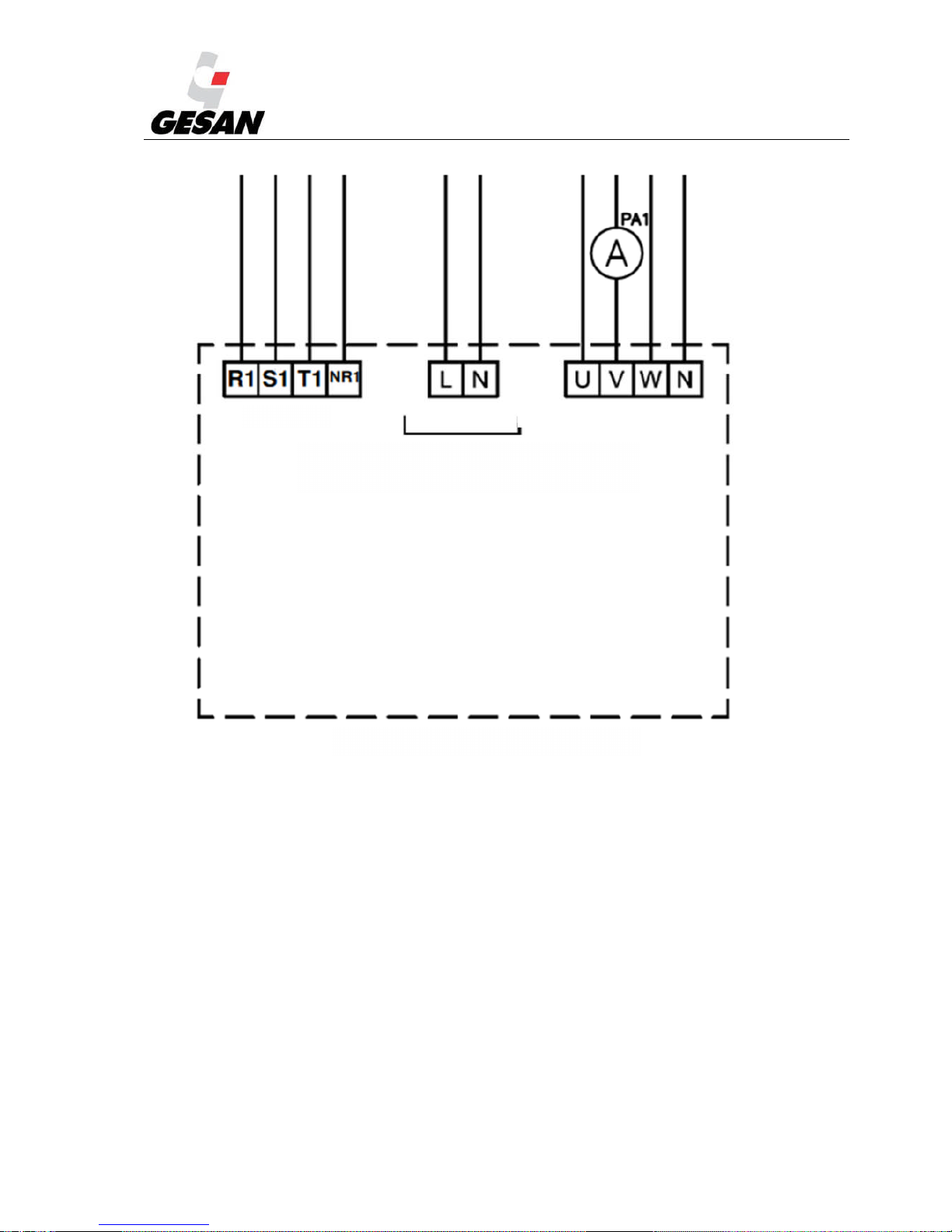
Antifreeze resistors, battery charger and heater connection:
Those connections are realized through L-N external power terminals.
Page 24
STANDBY GENERATOR SETS V-6.4
23
Image 14- Connecting external power input
-400/230 50 Hz: Phase-neutral connection.
-208/120 60 Hz: Phase-phase connection.
-220/127 60 Hz: Phase-phase connection.
-400/230 60 Hz: Phase-phase connection.
-480/277 60 Hz: Phase-neutral connection.
The unit manufactured by GRUPOS ELECTRÓGENOS EUROPA S.A., may or may not be supplied
with ATS (depends on electrical configuration: see section 3.3); if it is not supplied, it must be added by the
customer.
There are three kinds of different control switchgear used in GRUPOS ELECTRÓGENOS EUROPA
S.A. automatic transfer switch systems:
EXIT GENSET MAINS
MAINS
AUXILARY SYSTEM MAINS
230 V 50 Hz
USER CONNECTION
Page 25

STANDBY GENERATOR SETS V-6.4
24
Contactors: mechanically and electrically interlocked: They are manufactured from
40A to 125A.
Motor operated changeover switches: They are manufactured from 160A.
Motor operated circuit breakers: They are supplied only on customer request.
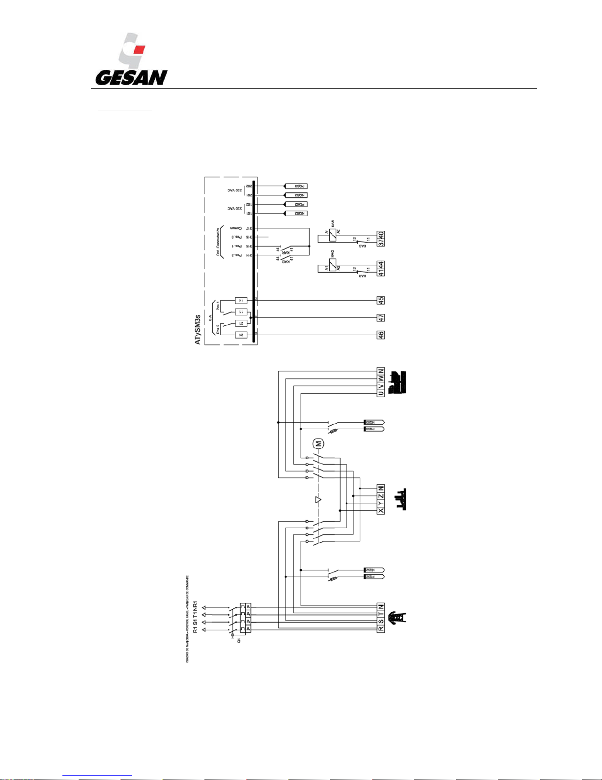
The following diagram shows a basic ATS setup.
Image 15- ATS setup
The electrical installation of the ATS is performed in two separate steps: firstly, the installation of the
CONTROL section and secondly, the ELECTRICAL POWER section.
Page 26
STANDBY GENERATOR SETS V-6.4
25
ATS schemes:
The electrical schemes of a typical ATS manufactured by GRUPOS ELECTRÓGENOS EUROPA S.A.
are:
a) ATS by contactors:
Image 16- Diagram of ATS Panel
Page 27

STANDBY GENERATOR SETS V-6.4
26
b) ATS by motorized contacts:
Image 17- Diagram of ATS Panel by motorized contactors
Page 28

STANDBY GENERATOR SETS V-6.4
27
4.2.7.2. Installation of CONTROL section :
The installation of the Control section can be done in three different ways:
1)ATS supplied by GRUPOS ELECTRÓGENOS EUROPA S.A.
2)ATS not supplied by GRUPOS ELECTRÓGENOS EUROPA S.A.
3)Unit is a “Standby by signal” type.
1) ATS provided by GRUPOS ELECTRÓGENOS EUROPA S.A.
a) Connect the terminals R1 S1 T1 NR1 on the control panel installed on the generator to the
ATS terminals equally named.
b) Connect the terminals numbered as 37, 40, 41, 44, of the control panel installed in the
genset to the ATS terminals equally named.
c) It´s not necessary to connect the terminals 38, 39, 40 and 43 of the genset control box.
d) Do not connect terminals 38-39-40-43 in the control panels.
In making these connections, you must use an 8-wire conductor of 1.5mm². This cable is not provided
with the generator set. The maximum distance between the control panel and the ATS panel should be 25m
for a 1.5mm² cross section and a generator set power of 650 kVA. In case of higher power or distance,
increase the cross section to avoid excessive voltage drop.
2) ATS not supplied by GRUPOS ELECTRÓGENOS EUROPA S.A.,
Check the user manual of the corresponding ATS and follow these steps:
Connect the terminals R1 S1 T1 NR1 of the control panel (referential mains
voltage) to the input of the electric company mains.
Connect the terminals numbered 37 to 47 (both inclusive) to the ATS control
panel (check the electrical setup on the generator set control panel).
Make sure that the electrical and mechanical interlocking is completed correctly.
Also make sure that the ATS that you want to install is compatible with the generator
unit provided.
The cable cross section must be appropriate for your installation.
Page 29

STANDBY GENERATOR SETS V-6.4
28
3) Generator unit is “Standby by signal” type:
Neither the generator set will monitor the mains nor control the ATS: these must be controlled
by the user’s management system.
The terminals through which the generator set receives the startup signal are 184 and 185, which should
be volt-free.
The generator set uses terminals 120 and 121 to return a volt-free signal when the voltage and frequency
of the generator set are correct.
Terminals R S T N should be connected to a mains input prior to the ATS, as these terminals provide the
power supply for the engine block heater and battery maintainer. The cable cross section should be
appropriate for your installation.
4.2.7.3. Installation of ELECTRICAL POWER section:
The power installation could be carried out in two ways:
1) ATS supplied by GRUPOS ELECTRÓGENOS EUROPA S.A.
- Connect the generator’s current output terminals U V W N to the ATS terminals U V W N.
- Connect the electric company’s power control switch (PCS) to terminals R S T N.
- Then connect ATS terminals X Y Z N to the installation.
2) ATS not supplied by GRUPOS ELECTRÓGENOS EUROPA S.A. or the generator set is the
“Standby via signal” type.
- Connect the generator’s current output terminals U V W N to the input of the ATS on the generator
set. Check the manual of your ATS.
This installation should be performed by qualified personnel, who should determine the conductor section
to be used.
Page 30
STANDBY GENERATOR SETS V-6.4
29
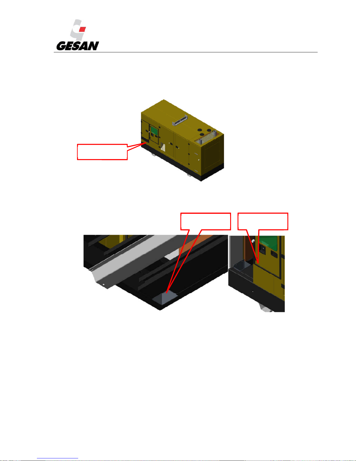
In isolated power box gensets, mains cable instalation could be realized by two ways:
-Lateral power cables outlet: This way, power cables come out by the trapdoor with protective rubber
placed in the control box door, as shown in the image:
Image 18- Lateral power cables trapdoor entry
-Power cables lower exit: This way, the power cables enter directly from the bedplate lower part throught
the duct adapted in the base.
Image 19- Power cables entry by bedplate
In the installation drawing you could find the exact measures, and also relative positions.
Lateral power cables
inlet.
Power cables lower
entry
Power cables lower
exit
Page 31

STANDBY GENERATOR SETS V-6.4
30
4.2.7.4. Earthing:
Ensure that the generator set, including mobile ones, is effectively grounded (earthed) in accordance with
every relevant regulation, electrical code, standard or other requirement, prior to start operations.
The electrical resistant of earthing installation must be enough low in order to allow earth leakage
protection systems to work properly and to limit the voltage in exposed conductive parts, to avoid dangers
to people or goods. Check regularly this value to avoid its increasing.
To avoid the transfer of currents or voltages from other electrical systems (for example, high voltage
network), independence between grounding systems must be guaranteed.
4.2.7.5. Motorized changeover switches:
Motorized changeover switches are a kind of special designed control switchgear for electrical networks
transfer, which simplify the equipment and control wiring needed.
Motorized changeover switches can also be manually operated. They include a handle key to network
switching in case of emergency when any power source is available.
For security purposes, the changeover switch can be padlocked in position 0 (then manual operations are
impossible and electrical controls are disabled).
For additional information, please consult manufacturer manual.
4.3. STORAGE
If you think your generator will be inactive for a long period of time, follow these instructions:
1) Switch the control module to the OFF position.
2) Press the emergency stop button to avoid future involuntary startups when connecting.
3) Empty the fuel tank.
4) Disconnect the battery.
5) Avoid storing the unit in spaces with high dust accumulation or excessive humidity.
6) Do not use pressurized water when cleaning the unit.
7) Check your engine manual for care instructions; the manual has been provided together
with this document.
8) Check your alternator manual for maintenance instructions; the manual has been provided
together with this document.
Page 32

STANDBY GENERATOR SETS V-6.4
31
5. STARTUP
Prior to start up the generator set, or after making a change in location, you must follow these steps:
1) Check the genset right mechanical balance and the right contact of every base support
with the floor.
2) Check and retighten, when necessary, radiator to base frame and radiator to motor screws.
3) Check and retighten, when necessary, engine-alternator coupling to base frame screws.
4) Check and adjust, when necessary, the fan belt and battery charger alternator belt
alignment. If generator set output is over 750 kVA, this recommendation turns into mandatory.
Please, contact with your distributor to request specific information to make this task.
5) Check canopy sealing material, especially in the roof. Clean and reseal when necessary.
6) Check battery connections, and retighten, clean and grease when necessary.
After checking the mechanical, in order to proceed to the genset shut down.
1)Check levels: oil, coolant and fuel.
2)Close the battery isolator switch.
3)Release the emergency push button if it has been pressed.
4)Connect to the mains power and verify that the voltage indicator is giving an adequate
reading.
5)Check circuit breaker (the lever must be above).
6)After completing the pre-startup tasks, make sure that the generator’s control module
switch is in the desired position. For this reason, the user should carefully read about the
operation of the control module in section 6 of the OPERATION MANUAL.
It is recommendable to run a simulation of mains failure to verify that the unit is functioning
properly.
To proceed with the genset stop:
1) Disconnect the batteries.
2) Disconnect the main switch.
3) Leave the engine running without load during 2 minutes in order to cool the genset.
4) Stop the engine completely, changing the control module switch to OFF position.
Page 33

STANDBY GENERATOR SETS V-6.4
32
5.1. POWER FACTOR AND GENERATOR SETS
The power factor (cos φ) of the generator set loads must be determined. Lagging power factor below 0,8
can overload the generator. It can work properly from 0,8 to 1 lagging power factor.
Special attention must be given to installation with power factor corrections equipment (based on
capacitors) in order to avoid leading power factor. This could prompt the generator set to voltage instability
and could result in dangerous over voltages. Whenever generator set is supplying the load, any power factor
correction equipment must be switched off.
5.2. LIGH LOAD OPERATION ON DIESEL ENGINES
If an engine is operated on a load less than 25-30% of its rated output, certain symptoms will be observed
which may be cause for concern. The engine is designed to run up to a maximum power and so the size of
the piston, the wall loading of the piston rings, etc., is designed for this.
When an engine is run at light load then the energy put into the cylinder is low and consequently the
cylinder pressure is lower and so is the temperature. The result is the piston to bore clearance is increased
allowing more oil to pass the piston and be burnt, which is indicated by high oil consumption.
Oil will start to appear from the manifolds from the bearing arrangement in the turbocharger.
Turbochargers are fitted to an engine to increase power by supplying more air to the cylinders. When
running a turbocharger, air is sucked in, which can have vacuum levels up to 500 mm H2O, with pressure
ratios of 3:1.The compressor seals are designed to work most efficiently when the turbocharger compressor
is operating at its’ most efficient point. If the engine is running at low powers then the turbocharger is
running at low speed (no energy from the exhaust because the fuel inlet to the engine is low) and the inlet
vacuum is low resulting in poor turbocharger seal loading and pull over of oil from the bearing assembly.
This oil is mixed with the air and pumped into the manifolds where some separates from the air when it
collides with the inside of the manifold. The manifold gaskets will become impregnated with oil, eventually
this will show as an oil leak from the manifold mating surfaces.
Black smoke will be produced from the exhaust outlets, due to poor combustion at light load, as excess
fuel is pumped through into the exhaust system, resulting in soot being expelled into the exhaust system.
A further result is that of abnormal carbon build-up on the valves, piston crowns and exhaust ports. Thus
the normal service interval of 2500 hours between top overhauls may be reduced. Fuel dilution of the
lubricating oil will also occur.
It is therefore recommended that the following precautions are observed:
Running on light load should be avoided or reduced to a minimum period. If weekly
exercising on no load is carried out, the running period should be kept down to maximum 15
minutes or until the battery charge rate returns to normal.
Page 34
STANDBY GENERATOR SETS V-6.4
33
Every year the engine / generating set should be run on full load for four (4) hours, to
burn off accumulations of carbon in the engine and exhaust system. This may require a “dummy”
load. The load should be built-up gradually from zero over the four hour run.
If you expect prolonged operation at low load is necessary to plan an additional charge
through resistor banks.
6. OPERATION MANUAL
Never, under no circumstance shall the generator adjustment parameters be modified. Consult with the
Technical Service if the parameters need to be modified.
The generator set you purchased was designed for standby use, which means that it will mainly be
operational when the mains voltage is inadequate.
Therefore it is necessary to connect the mains to the unit’s ATS as well as to the generator set (see section
4 – Installation).
The following is a description of the different variable elements, according to the generator set chosen.
6.1. CONTROL PANEL COMPONENTS
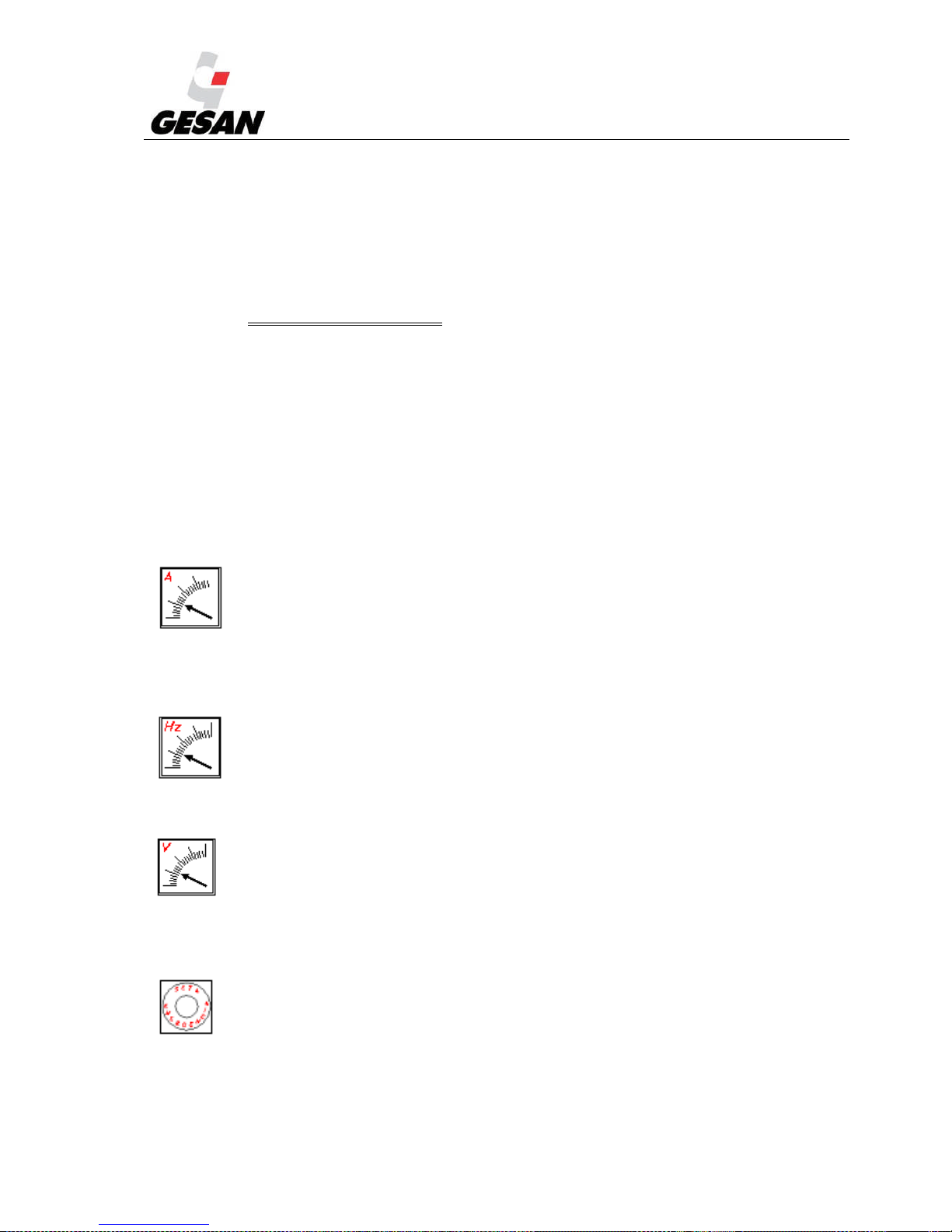
Ammeter:
Is an indicator of the current generated (A), by means of a switch, you may read the same of the different
phases of the generator set.
Frequency meter:
Is an Indicator the frequency of the generator set (Hz).
Voltmeter:
Is an indicator of the voltage (V) of the main power supply or generator set, depending on the position of
the voltmeter switch (Ph-Ph, Ph-N).
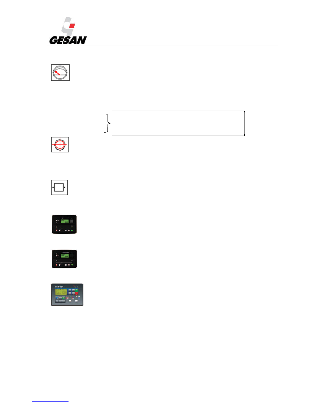
Emergency stop button:
Pressing this button brings the generator set to an immediate stop. To cancel, turn to the left, assuring
plenty of the end of the emergency.
Page 35
STANDBY GENERATOR SETS V-6.4
34
Gauges indicating engine parameters:
Oil Pressure
Battery charger current
Engine Temperature
Fuel Level
Diagnostic Button:
Allows engine parameters to be checked when generator set is stopped (electronically controlled engines).
Also gives readout of the generator’s different alarms.
Differential:
Protection against earth leakage of one phase, switching off the generator set circuit breaker.
DEEP SEA 4420, Control module which controls the mains, and if it fails, the genset
startup.
DEEP SEA 7320, control module which controls the mains, and if it fails, the genset
startup.
ComAp INTELIGENT (optional). Automatic control module which controls the mains,
and if it fails, the genset startup.
Activated by temperature and fuel button when
generator set is stopped. When the generator is
operating, the gauges show the corresponding levels.
Page 36
STANDBY GENERATOR SETS V-6.4
35
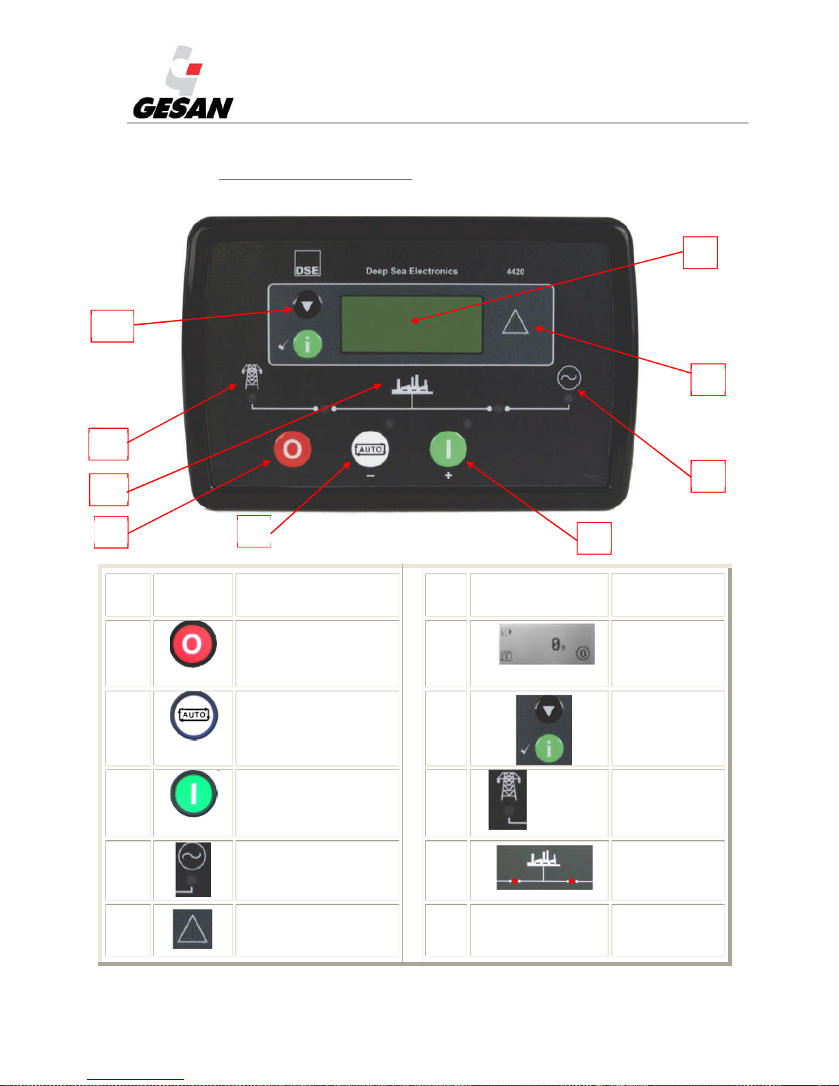
6.1.1. Deep sea 4420 digital control module
Image 20- Deep Sea 4420 Control Module
SYÍMBO
L
DESCRIPTIÓN SYMBOL DESCRIPT
IÓN
(1) Stop / Manual mode
/ Reset button
(9) Status
generator set
display
(2) AUTOMATIC mode
button
(10) Menu
navigator
(3) Generator set start up
button
(11) Mains
available
(4) Generator led (12) Status of
ATS for
mains and
generator set.
(8) Warning “!”.
1
2
3
4
8
9
10
11
12
Page 37
STANDBY GENERATOR SETS V-6.4
36
Deep Sea 4420 is an automatic control module that monitors the main power supply; if a mains failure
occurs, generator set will start up and loads are transferred. This control module also allows the option of
manual startup. The user can also control all of the generator unit’s parameters as well as the status of
mains power supply. This model is supplied with standby generator sets with or without ATS.
Deep Sea 4410 control module is supplied with “stand-by by signal” type units.
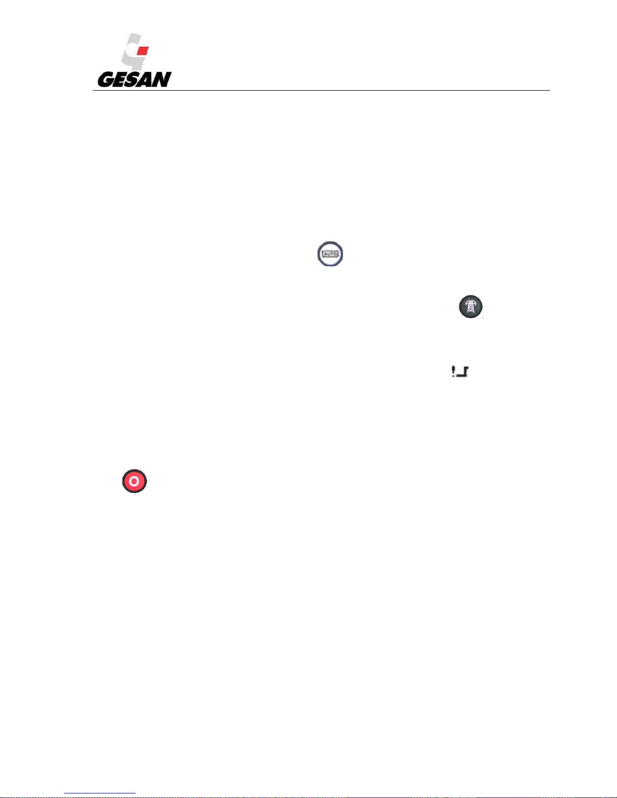
AUTOMATIC Mode (AUTO):
This is the normal operating mode.
The automatic mode is activated by pressing the button (4), at which point the LED at the top of
the button will turn on, indicating that it is operational.
If the mains power supply fails for longer than the unit’s programmed period, the LED (11)
indicating that the mains power is available will be turned off.
The engine will start; if it should fail, there will be a maximum number of startup attempts (3). If all three
startup attempts have been unsuccessful, the information screen will display a startup alarm:
When mains power is restored (or when the remote startup signal disappears) there will be a period of
time in which the engine will continue operating at no load to cool down before stopping completely.
If a mains failure occurs or remote startup signal appears again during the no-load operating period (cool-
down period), the generator set would begin the startup process again.
Press (1) or the emergency stop button to intentionally stop the unit.
Page 38
STANDBY GENERATOR SETS V-6.4
37
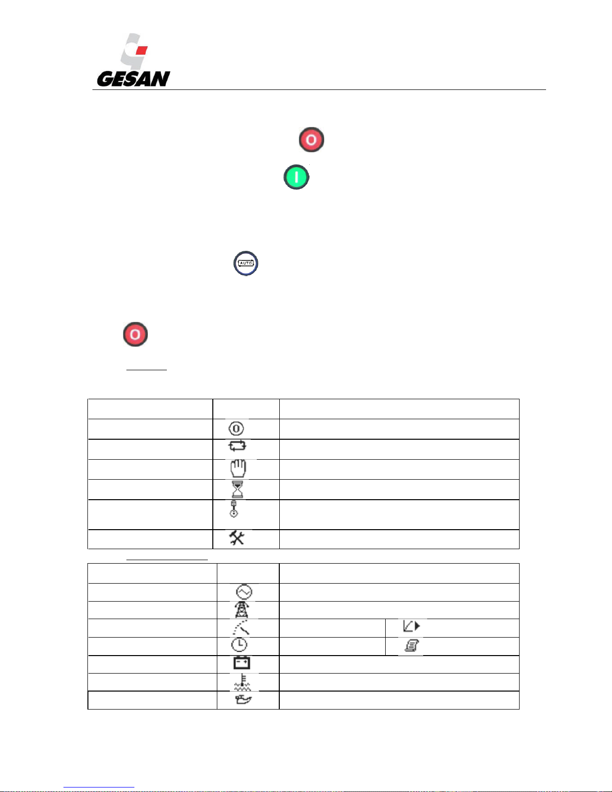
MANUAL Mode:
The manual mode is activated by pressing the button ,
To begin the starting sequence, press the button.
If a mains failure occurs, a remote startup signal is received; loads will be transferred to the generator set.
Once the load has been transferred to the generator, it will not be automatically transferred back to the
mains supply.
To terminate this mode, press the (2) button, once is pressed and there is adequate mains power
supply (without the remote startup signal activated), the shutdown sequence will begin as described in the
automatic mode.
Press (1) or the emergency stop button to intentionally stop the unit.
.Mode icon
An icon is displayed in the mode icon area of the display to indicate what mode the unit is currently in.
Icon
Graphi
c
Details
Stopped Appears when the engine is at rest and the unit is in
stop mode.
Auto Appears when the engine is at rest and the unit is in
auto mode.
Manual Appears when the engine is at rest and the unit is in
manual mode.
Timer animation Appears when a timer is active, for example cranking
time, crank rest etc.
Running animation Appears when the engine is running, and all timers
have expired, either on or off load. The animation will
be rate is reduced when running in idle mode.
Front panel editor Appears when the unit is in the front panel editor
.Instrumentation icons
Icon
Graph
ic
Details
Generator Used for generator voltage and generator frequency
Mains Used for mains voltages and mains frequency
Engine speed Flexible sensor
Hours Run Event log
Battery voltage
Engine temperature
Oil pressure
Page 39
STANDBY GENERATOR SETS V-6.4
38
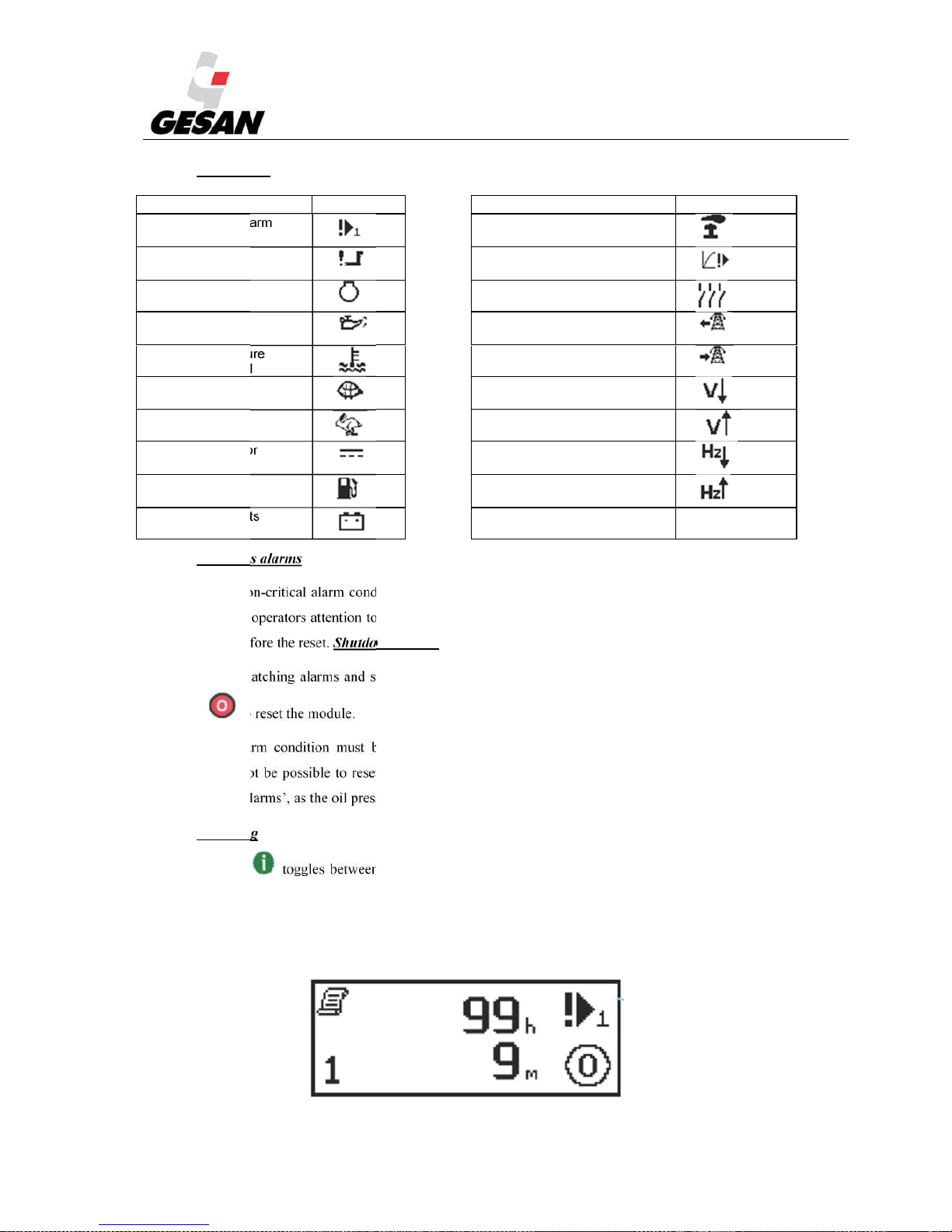
Alarm icons
Alarm
Icon
Alarm
Icon
External input alarm Emergency stop
Failed to start Flexible sender alarms
Failed to stop Generator contactor
alarm
Low oil pressure
Mains Failure
Water temperature
/ Low coolant level
Mains Return
Under speed Under voltage
Over speed Over voltage
Charge alternator Under frequency
Low fuel Over frequency
Plant battery volts
(under/over)
Warnings alarms
Warnings are non-critical alarm conditions and do not affect the operation of the generator system, they
serve to draw the operators attention to an undesirable condition. The condition that provokes the warning
must be solved before the reset. Shutdown alarms
Shutdowns are latching alarms and stop the Generator. Clear the alarm and remove the fault then press
Stop/Reset to reset the module.
NOTE: The alarm condition must be rectified before a reset will take place. If the alarm condition
remains, it will not be possible to reset the unit (The exception to this is the Low Oil Pressure alarm and
similar ‘delayed alarms’, as the oil pressure will be low with the engine at rest).
Event log
The info button toggles between the display of the instrumentation and the event log. Pressing the
down button will move to the previous event, the event log entry at position 1 being the most recent. On
moving from the instrumentation value to the event log the unit will display the most recent entry.
Example of Auxiliary Input Shutdown Alarm..
Page 40
STANDBY GENERATOR SETS V-6.4
39
6.1.2. DEEP SEA 7310/7320 Digital Control Module
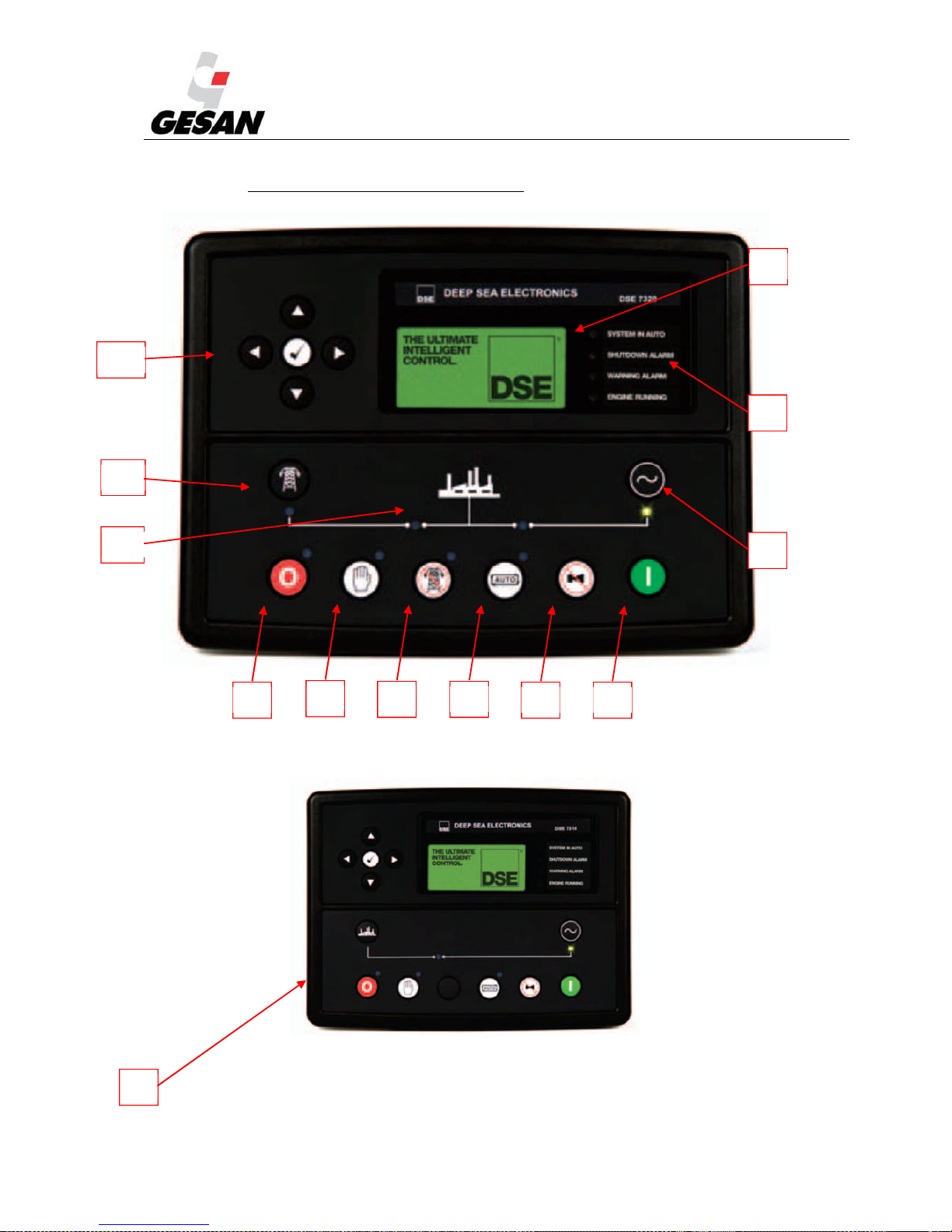
Image 21- Deep Sea 7320 Control Module
Image 22- Deep Sea 7310 Control Module
1
2
3 4
5 6
7
8
9
10
11
12
A
Page 41
STANDBY GENERATOR SETS V-6.4
40
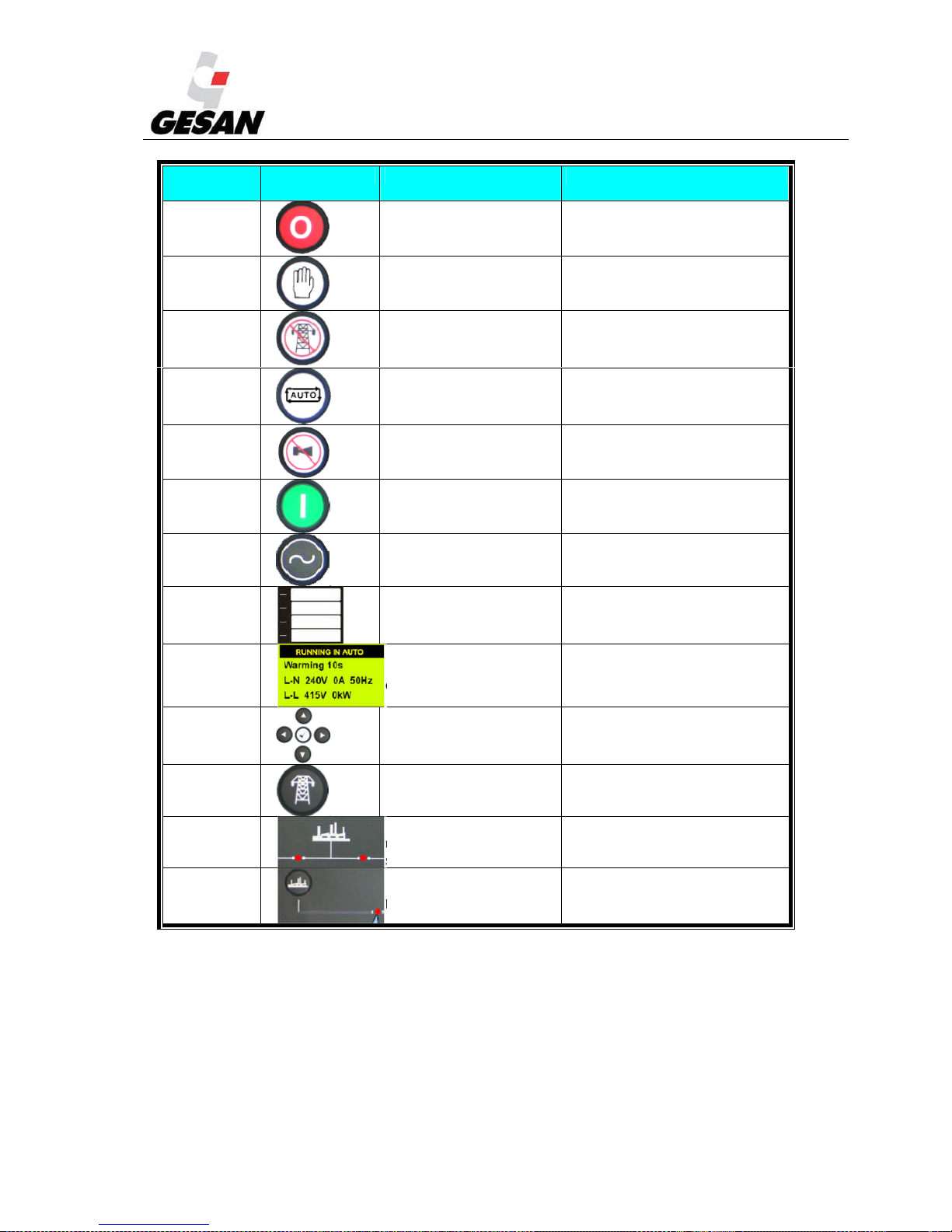
NUMB
ER
SYMBOL DESCRIPTION IDENTIFICATION
(1) Stop button. Red LED
(2)
MANUAL mode
button
Red LED
(3) TEST mode button
Green LED (available on
model 7320 only)
(4)
AUTOMATIC mode
button
Red LED
(5)
Mute alarm / Lamp
test button
(6)
Generator set start up
button
(7)
“Transfer to
generator” button
Green LED on when
generator set is available
(8)
Configurable LED
indicators.
Red LED
(9)
Status generator set
display.
(10) Menu navigator
(11)
”Transfer to mains”
button
Green LED (available on
Model 7320 only)
(12)
Status of ATS for
mains and generator
set.
Left LED on: mains closed /
Right LED on: generator
closed.
(A)
“Open generator”
button
LED on: generator set is
supplying loads.
Deep Sea 7320 is an automatic control module that monitors the main power supply; if a mains failure
occurs, generator set will start up and loads are transferred. This control module also allows the option of
manual startup. The user can also control all of the generator unit’s parameters as well as the status of
mains power supply. This model is supplied with standby generator sets with or without ATS.
Deep Sea 7310 control module is supplied with “standby by signal” type units.
Page 42

STANDBY GENERATOR SETS V-6.4
41
AUTOMATIC mode (AUTO):
This is the normal operating mode.
The automatic mode is activated by pressing the button (4), at which point the LED at the top of
the button will turn on, indicating that it is operational.
(7320) If the mains power supply fails for longer than the unit’s programmed period, the LED
(7310) If a mains failure occurs, the external management system should send a startup signal to the
generator set, at which point the LED indicating remote startup active (8) turns on and the startup process
of the generator set begins.
The engine will start; if it should fail, there will be a maximum number of startup attempts (3). If all three
startup attempts have been unsuccessful, the information screen will display a startup alarm:
When mains power is restored (or when the remote startup signal disappears) there will be a period of
time in which the engine will continue operating at no load to cool down before stopping completely.
If a mains failure occurs or remote startup signal appears again during the no-load operating period (cool-
down period), the generator set would begin the startup process again.
Press (1) or the emergency stop button to intentionally stop the unit.
MANUAL mode: The manual mode is activated by pressing the button (2), at which point
the LED at the top of the button will turn on, indicating that it is operational.
Press (6) to start up the unit.
If a mains failure occurs, a remote startup signal is received or “transfer to generator” button (7) is
pressed, loads will be transferred to the generator set. Once the load has been transferred to the generator, It
will not be automatically transferred back to the mains supply.
Loads can be manually transfer back to mains pressing “transfer to mains” button (11) (7320) or
pressing “open generator” button (A) (7310).
To terminate this mode, press the button (4).
Once button (4) is pressed and there is adequate mains power supply (without the remote startup signal
activated), the shutdown sequence will begin as described in the automatic mode.
Press (1) or the emergency stop button to intentionally stop the unit.
Page 43
STANDBY GENERATOR SETS V-6.4
42
LOAD TEST mode (7320):
A test for proper functioning of the generator set can be done pressing (3).
To start up, press the start button (6).
In this operating mode, a mains failure is simulated, with the loads being transferred to the generator set.
To terminate this mode, press the button (4).
Once button (4) is pressed and there is adequate mains power supply (without the remote startup
signal activated), the shutdown sequence will begin as described in the automatic mode. After this period of
time, the load will be carried by the mains power.
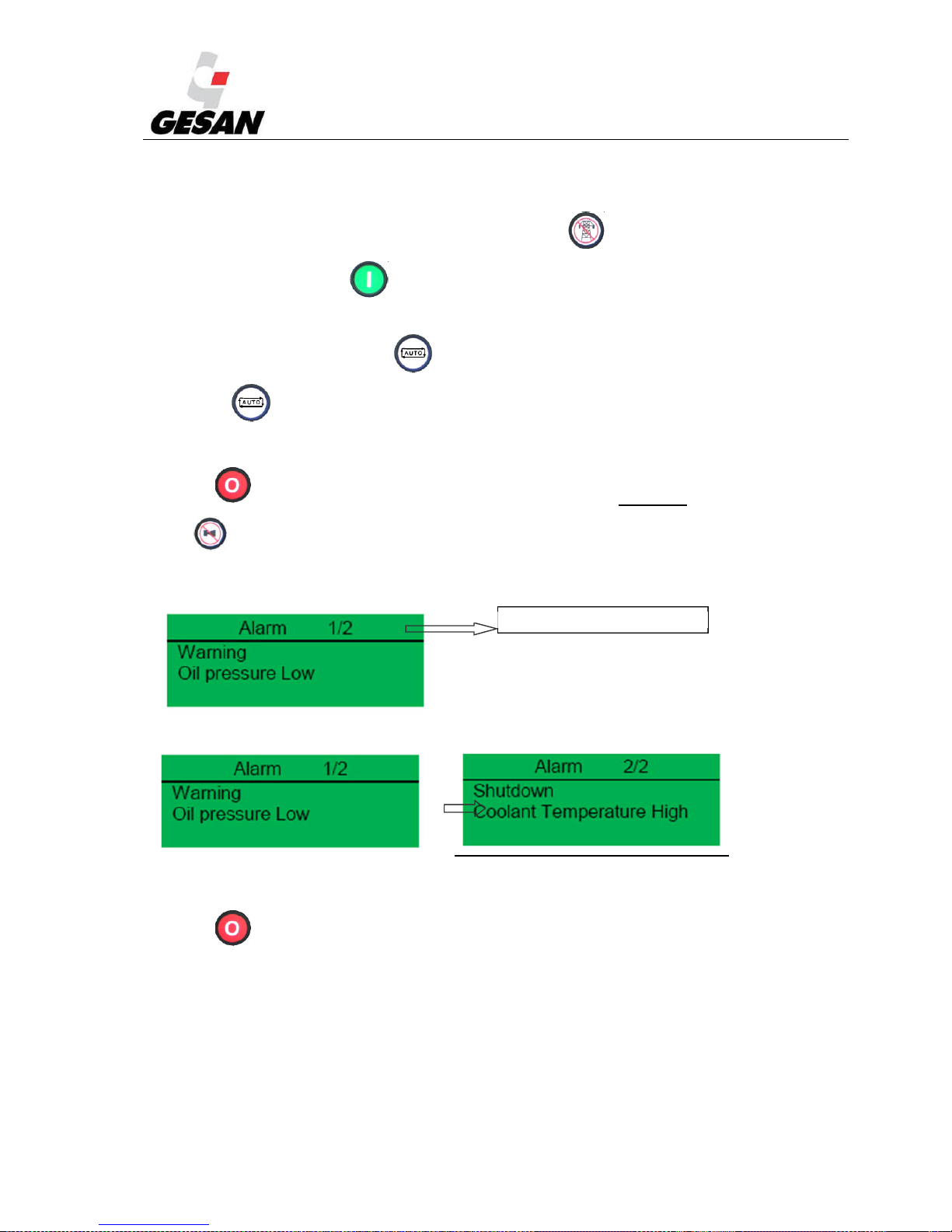
Press (1) or the emergency stop button to intentionally stop the unit.ALARMS:
Press (5) to silence the audible alarm and acknowledge the common alarm LED.
By default, the information screen will show the status screen and if an alarm occurs, the screen will
display the following:
If shutdown occurs while a warning is active, the screen will cycle through the active alarms:
The warnings do not entail generator unit shutdown.
Press (1) to reset all the alarms which causes the stops. If the cause which caused the alarm has
not gone we cannot reset the board
Alarm 1 of a total of 2 present alarms
Page 44
STANDBY GENERATOR SETS V-6.4
43
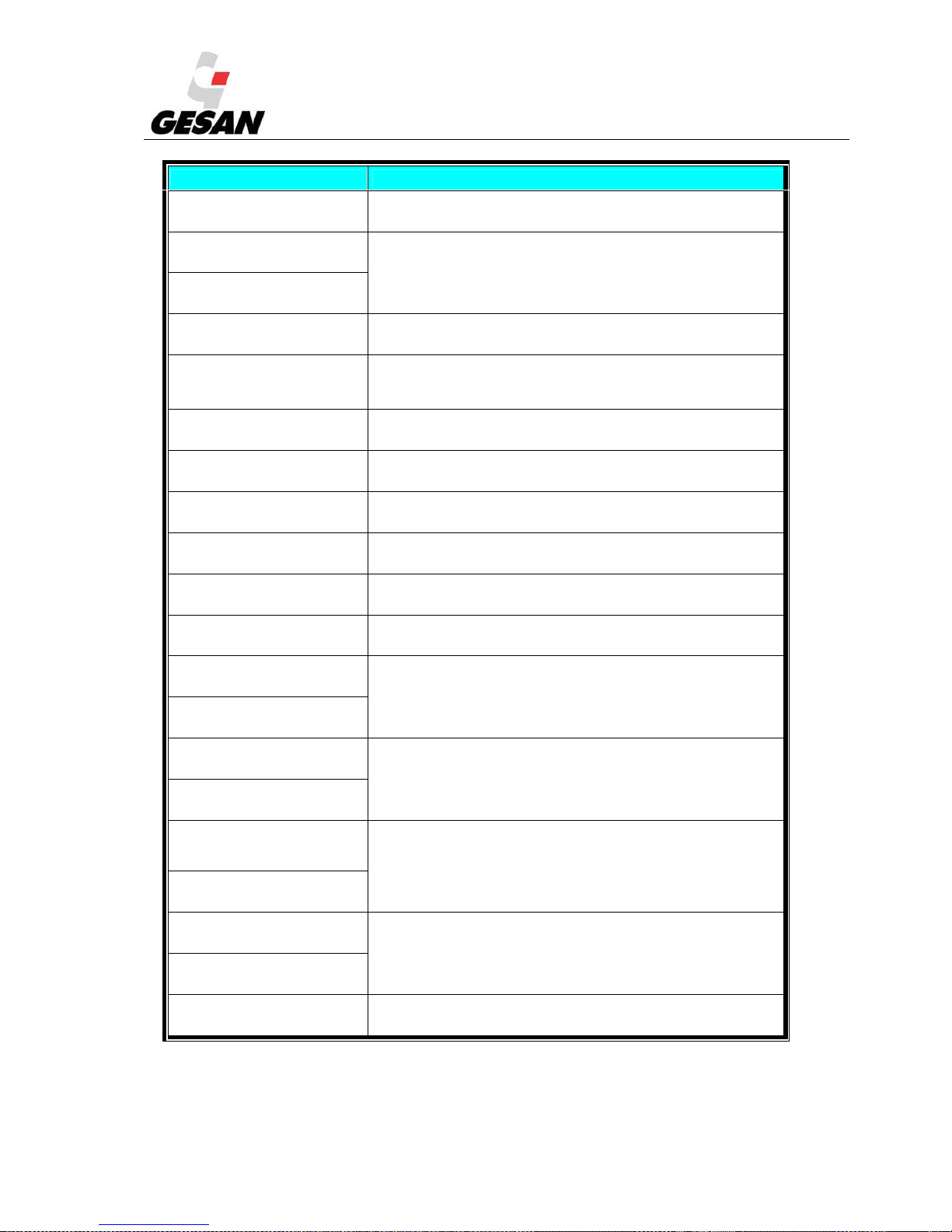
INCIDENT ALARM DESCRIPTIONS
ALARM
Warning
Charge failure
Charge alternator voltage not detected
ALARM
Warning
Battery under voltage
Battery voltage beyond established limits
ALARM
Warning
Battery over voltage
ALARM
Warning
Fail to Stop
After shutdown command, engine continues running.
Could also indicate faulty oil pressure sender
ALARM
Warning
Auxiliary inputs
Auxiliary inputs can be configured and will display the
message as written by the user
ALARM
Warning
Low fuel level
Fuel level below established limits
ALARM
Warning
CAN ECU error
Engine ECU has detected a warning alarm. The exact error is
also indicated on module display (only for electronic engines).
ALARM
Warning
kW overload
The total kW are above the warning setting.
ALARM
Warning
Earth fault
The earth fault current is above alarm settings (only under
customer request)
ALARM
Warning
Negative phase sequence
Indicates “out of balance” current loading of the generator set.
ALARM
Warning
Low oil Pressure
Low oil pressure, below established limit
ALARM
Warning
Engine high temperature
Engine temperature beyond established limits
ALARM
Warning
Engine low temperature
ALARM
Warning
Underspeed
Engine speed beyond established limits
ALARM
Warning
Overspeed
ALARM
Warning
Generator over frequency
Generator set frequency beyond established limits
ALARM
Warning
Generator under frequency
ALARM
Warning
Generator over voltage
Generator set voltage beyond established limit
ALARM
Warning
Generator under voltage
ALARM
Warning
High Current
Current of the generator set output beyond established limits
Page 45
STANDBY GENERATOR SETS V-6.4
44
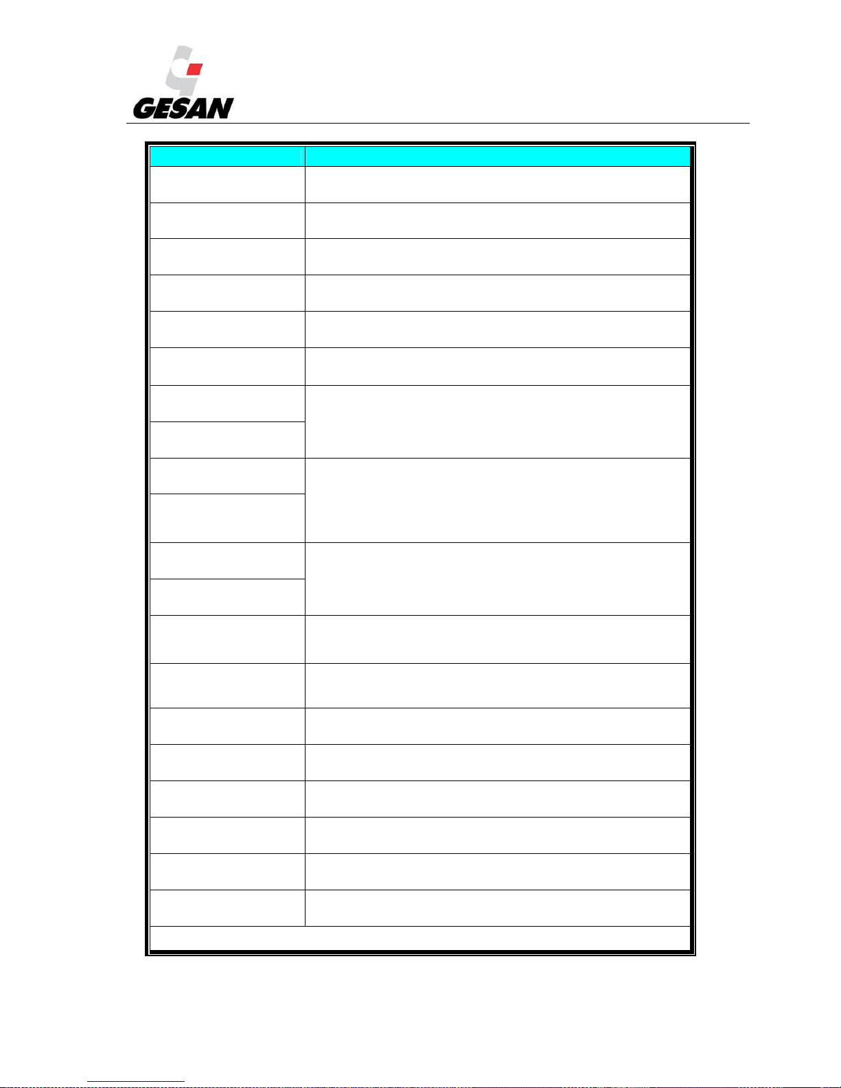
INCIDENT DESCRIPTION OF SHUTDOWNS
ALARM
Shutdown
Earth fault
The earth fault current is above shutdown settings (only under
customer request)
ALARM
Shutdown
Failed to Start
Engine does not start, three attempts made.
ALARM
Shutdown
Emergency stop
Controlled shutdown of the unit. It will not be functional until the
emergency stop button has been reset.
ALARM
Shutdown
Low oil pressure
Oil pressure below established limit
ALARM
Shutdown
High temperature
Engine temperature above established limit
ALARM
Shutdown
Phase rotation
The phase rotation is different to the configured direction
ALARM
Shutdown
Overspeed
Engine speed beyond established limits
ALARM
Shutdown
Underspeed
ALARM
Shutdown
Generator over frequency
Generator set frequency beyond established limits
ALARM
Shutdown
Generatp
or under frequency
ALARM
Shutdown
Generator over voltage
Generator set voltage beyond established limit
ALARM
Shutdown
Generator under voltage
ALARM
Shutdown
Oil pressure sender open
circuit
Faulty oil pressure sender
ALARM
Shutdown
Auxiliary input
An active auxiliary input configured as a shutdown will cause the
engine to shutdown. The display shows the text as configured by
the user.
ALARM
Shutdown
Loss o speed signal
The speed signal from magnetic pick up as not received by the
module.
ALARM
Shutdown
ECU data fail
The module configured for CAN operation and doesn´t detect
data on data link.
ALARM
Shutdown
ECU shutdown
Engine ECU has detected a shutdown alarm. The exact error is
also indicated on module display (only for electronic engines).
ALARM
Shutdown
kW overload
The total kW is above the shutdown setting.
ALARM
Shutdown
Negative phase sequence
Indicates “out of balance” current loading of the generator set.
ALARM
Shutdown
High Current trip
Current of the generator set output beyond established limits
Note: If the established limit for shutdown is exceeded, a corresponding alarm screen will be displayed and on the
configurable LED indicator (8) the Common Shutdown alarm will appear.
Page 46
STANDBY GENERATOR SETS V-6.4
45
INCIDENT DESCRIPTION OF ELECTRICAL TRIPS
ALARM
Electrical trip
Generator over current
Generator set current above electrical trip setting.
ALARM
Electrical trip
Auxiliary inputs
Auxiliary inputs can be configured and will display the message
as written by the user
ALARM
Electrical trip
kW overload
The total kW is above electrical trip setting.
ALARM
Electrical trip
Earth fault
The earth fault current is above electrical trip settings (only under
customer request)
ALARM
Electrical trip
Negative phase sequence
Indicates “out of balance” current loading of the generator set.
Note: Electrical trips are latching and stop the generator set but in a controlled manner. Firstly de-energize the “close
generator” output to remove the load from the generator set, and later, cool down and shutdown the unit.
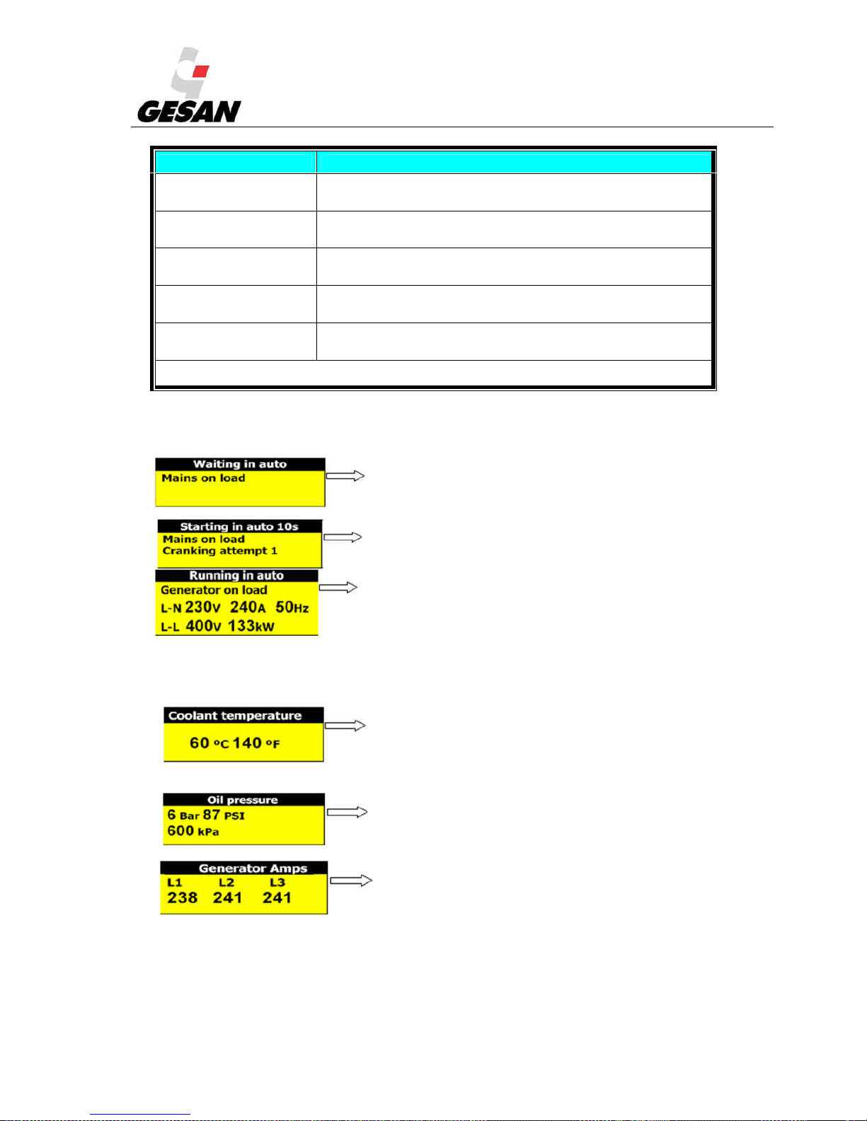
Typical LCD Display Screens
Indicates that the generator set will respond to either a
mains failure or an active remote start.
Indicates that generator set is in automatic mode and has
been initiated after a mains failure has been detected.
Indicates generator set running normally in automatic
mode. Also indicates the average line to neutral voltage (LN), the highest of the three phase currents, the rated
frequency, average line-to-line voltage (L-L) and total kilowatts.
Measurement Parameter Display Screens:
Coolant temperature in degrees (ºC) Celsius and degrees
Fahrenheit (ºF)
Displays engine oil pressure in Bar, PSI and kPa.
All three generator line currents.
Page 47
STANDBY GENERATOR SETS V-6.4
46
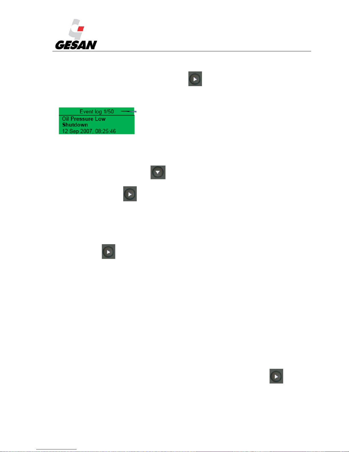
Event Log:
To view the event log, press the following button repeatedly until the LCD display the event log.
It registers the shutdown alarms occurring in the generator unit. A screen similar to this is shown:
“On September 12, 2007, at 08:25:46, the unit detected that the oil pressure was below the minimum
level and has shut down the generator. It´s the event 1 of a total of 50 logged events”
To move from one event to the next, press .
To exit the main screen, press .
Note: Warning alarms are not logged.
Displaying information:
Pressing this button: .
Page order:
Status display
Instrument display (engine, generator and mains)
Alarms display
ECU DTCs (electronic engines only)
Event Log
Scheduler (if enabled)
About
It is possible to scroll through the different display screens by pressing the next page button: .
Once selected, the page will remain on the screen until the user selects a different page or after a period of
inactivity for the control module, at which point the status display appears.
Page 48

STANDBY GENERATOR SETS V-6.4
47
If no buttons are pressed upon entering an instrumentation page, the instruments will be displayed
automatically.
Alternatively, by pressing on or buttons, the user can scroll through all the instruments on
a particular screen. This disables autoscroll. When autoscroll is disabled, if no buttons are pressed the
display will return to the status page. To re-enable autoscroll, press on or buttons to scroll to
the title of the instrument page.
If an alarm becomes activated while viewing instruments, the Alarms page will be automatically
displayed.
Instrument page content:
Engine
Engine speed
Oil pressure
Coolant
temperature
Engine battery volts
Run time
Oil temperature*
Coolant
temperature*
Inlet temperature*
Exhaust
temperature*
Fuel temperature*
Turbo pressure*
Fuel pressure*
Fuel consumption*
Fuel used*
Fuel level*
Auxiliary sensors
(if fitted and configured)
Engine mantenience
due (if configured)
Engine ECU link*
* When connected to suitably configured and compatible engine ECU.
Generator
Generator AC voltage L-N
Generator AC voltage L-L
Generator frequency
Generator current
Generator earth current (under customer request)
Page 49

STANDBY GENERATOR SETS V-6.4
48
Generator load (kW)
Generator load (kVA)
Generator power factor
Generator load (kVAr)
Generator load (kWh, kWAh, kVArh)
Generator phase sequence
Mains (DSE 7320 only)
Mains voltage L-N
Mains voltage L-L
Mains frequency
About
Module type
Application version
USB ID – unique identifier for PC USB connection
Analogue measurements version
Firmware update boot loader version
If the following appears in an instrument display: *****, this means that the engine can’t provide this
parameter; the control module, however, does provide this option.
If the following appears in an instrument display: ####### with the generator set in OFF/AUTOMATIC
mode (with the engine stopped), this means that the control module is not connected to the engine. Press
this button (6) to display the given value.
Alarm LED:
Remote start on load
Overload pre
-
alarm
Common alarms
Common shutdown
Page 50

STANDBY GENERATOR SETS V-6.4
49
Editing the current Date and Time:
The date and time are adjustable. When the battery is disconnected, the date and time are frozen; when
the battery is reconnected, the date and time shown will be from the last time the battery was disconnected.
The date and time reflected in the Event Log will be taken from the configuration according to the
following steps:
Press and simultaneously, then enter the correct PIN number using or
buttons to select the right figure, and using and to move from one figure to another. Finally
press button
Press until the Display section. Press until “Current date and time”.
When “Current Date and Time” appears, press the button. The figures will start to flash. Press
or to adjust to the desired values.
Press the button to confirm the value entered.
Press and hold to exit the editor at any time.
Page 51

STANDBY GENERATOR SETS V-6.4
50
6.1.3. INTELIGENNTDigital Control Module
Image 23- INTELIGENNTDigital Control Module
# SYMBOL DESCRIPTION IDENTIFICATION
(1)
Scrolls through
different operating
modes
OFF←MAN←AUT←TEST
(2) OFF→MAN→AUT→TEST
(3)
Deactivates audible
alarm
(4) Fault reset Acknowledges faults and alarms
(5) Start button In manual mode
(6) Stop button In manual mode
(7) MCB ON/OFF Opens and closes MCB in manual mode
(8) GCB ON/OFF Opens and closes GCB in manual mode
(9)
Exit from actual
screen (without save
changes if editing)
(10)
Selects on-screen
value, set point, history
record or
increase/decrease set
point value
Increases value
(11) Decreasesvalue
Page 52
STANDBY GENERATOR SETS V-6.4
51
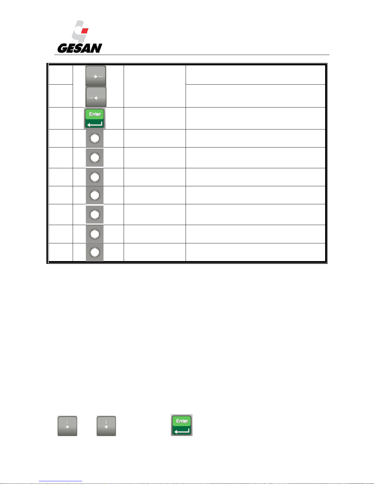
(12)
Moves history record
displayed columns to
the right/left, 5%
increase/decrease of
edited set point, a value
or go out/into alarm list.
6.1.4. Increases value
(13) Decreasesvalue
(14) Enter button Confirms on-screen value
(15) Mains power status Green if mains power correct
(16) Mains failure
Red light flashes if mains failure occurs and generator set
doesn´t run; continuous if generator is operating, turns off when
Mains power restored.
(17)
Generator voltage
present
Green led is on if unit voltage is present and within limits.
(18) Generator set failure Flashing Red LED indicates alarm
(19) State of GCB
Green led is on if GCB is closed. Flashes during synchronization
with mains.
(20) State of MCB
Green led is on if MCB is closed Flashes during reverse
synchronization with mains.
(21) State of bus Green led is on if bus voltage is correct
NOTE: GCB = Generator Circuit Breaker; MCB = Mains Circuit Breaker.
The InteliGenNTmodule contains a main menu screen and the following seven submenu screens:
Alarmlist
Measurement
Measurement I/O
History
Setpoints
User/Password
Languages
Pressing several times the main menu is displayed. To enter in a submenu, scroll up and down using
(10) or (11) buttons and press (14) button. To display the different instruments
Page 53
STANDBY GENERATOR SETS V-6.4
52
or parameters on each screen menu, press (10) or (11) buttons. To come back to a
previous menu screen, press . (9) button.
The alarmlist screen display the alarms detected by the module. Pressing button (4) faults and
alarms are acknowledged.
The measurement screen displays the parameters measured on the engine; if the engine uses an electronic
management system, many additional parameters can be displayed. In addition to these parameters,
measurements can be displayed for fuel level, oil pressure, current, voltage, frequency, run hours and
battery charge level.
The measurement I/O screen display the status of digital inputs and outputs and the measured parameter
of analogue inputs (senders).
The history screen menu displays the log of alarms that have occurred in the generator unit. It also logs
the opening and closing of the mains circuit breaker as well as the starting and shutting down of the
generator unit.
The set points menu screen displays the adjustment parameters already configured; it is not necessary to
edit any of these.
The users/password screen allows to define users and passwords. The languages screen allows to change
the display language
AUTOMATIC mode (AUTO):
If a mains failure is detected, the InteliGenNTmodule will open the MCB (main circuit breaker). Startup
command is issued to generator set. If generator voltage is within the established limits, the LED indicator
(17) will be on and the control module closes the GCB (generator circuit breaker). Once mains
power has been restored, synchronization between mains and generator occurs; then the MCB is closed,
causing the generator to discharge, followed by the opening of the GCB. When mains power is restored,
there will be a period of time during which the engine continues operating at no load to cool down before
stopping completely.
Note: If (4) is pressed following a disconnection alarm, the engine could automatically start without any warning.
Page 54
STANDBY GENERATOR SETS V-6.4
53
NO-LOAD TEST mode (MANUAL):
Press the START button (5) to start up the generator set. When the generator voltage is within
the established limits, the LED indicator (17) will be on. To stop the unit, press STOP
(6).
LOAD TEST mode (TEST):
This operating mode is used for generator set start test is the mains is OK or to transfer the load to the
generator set when a mains failure is announced in advance. To stop this mode, change to another mode by
means of the buttons (1) or (2).
OFF mode:
The generator set will not start. Even if we press the buttons START (5), STOP (6) ,
GCB ON/OFF (8), the generator will not respond.
Page 55
STANDBY GENERATOR SETS V-6.4
54
ALARMS:
The InteliGenNTcontrol module includes the following warnings:
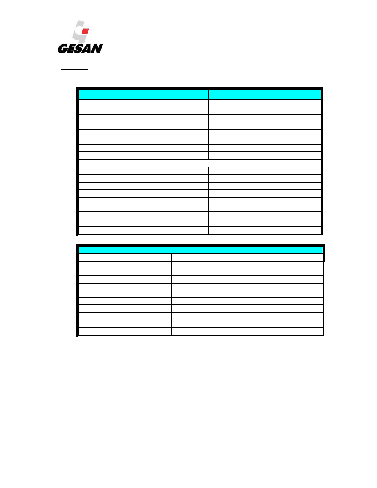
INCIDENT STORED IN HISTORY RECORD
Startup sequence initiated Startup of Gen-Set
Shutdown of the Gen-Set Gen-Set stops
Electrical Generator circuit breaker closed GCB connected
Electrical Generator circuit breaker opened GCB disconnected
Some GCB in group was opened (in MINT) Other GCB trip
Mains circuit breaker closed MCB connected
Mains circuit breaker opened MCB disconnected
Time mode has been changed TimeModeChngd
STARTUP INFO
AMF Startup GenSetMF start
AMF Stop GenSetMF stop
Remote startup by binary input (SPM, SPtM) GenSetRemStart
Remote stop by binary input (SPM, SPtM) GenSetRemStop
System startup by binary input (MINT,
MEXT)
GenSetSysStart
System stop by binary input (MINT, MEXT) GenSetSysStop
Peak start (SPtM) GenSet PKstart
Peak stop (SPtM) GenSet PKstop
ENGINE
EVENT SPECIFICATION ALARM HISTORY
Electrical Generator Startup
failure
Sd Start Fail Sd Start Fail
Electrical Generator Overspeed Sd Overspeed Sd Overspeed
Electrical Generator
Underspeed
Sd Underspeed Sd Underspeed
SD Stop fail Sd Stop Fail Sd Stop Fail
Emergency Stop Emergency Stop Emergency Stop
RPM Pickup fail SdPickupFail SdPickupFail
Battery voltage warning Wrn Batt volt Wrn Batt volt
Battery is discharged Sd Batt flat 0
Page 56
STANDBY GENERATOR SETS V-6.4
55
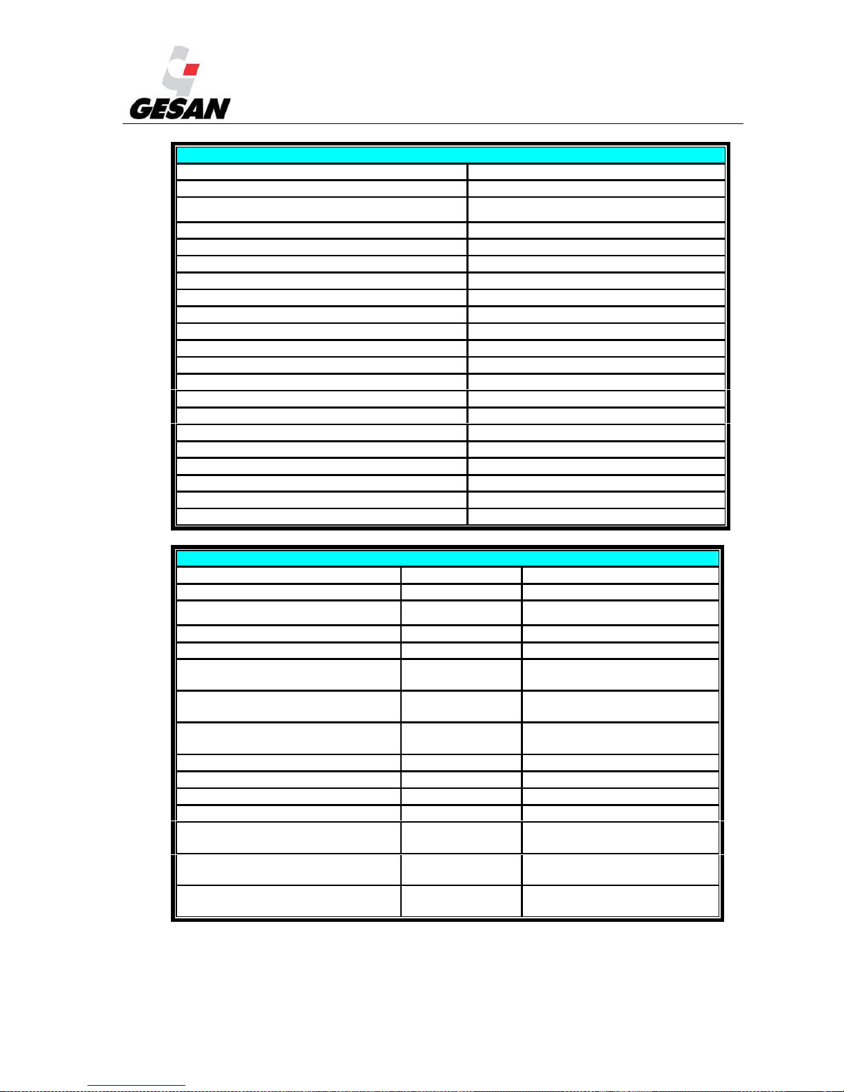
GENERATOR
EVENT SPECIFICATION HISTORY
Generator phase 1 overvoltage Unl Vg1 Over
Generator phase 1 undervoltage Unl Vg1 Under
Generator phase 2 overvoltage Unl Vg2 Over
Generator phase 2 undervoltage Unl Vg2 Under
Generator phase 3 overvoltage Unl Vg3 Over
Generator phase 3 undervoltage Unl Vg3 Under
Generator Overfrequency Unl Fgen Over
Generator Underfrequency Unl Fgen Under
Generator voltage unbalance Unl Vgen Unbal
Generator overload UnlGen Overload
Load surge protection LoadSurge
Reverse power Unl Rev Pwr
Synchronization timeout Stp SyncTO
Ground fault protection Unl EarthFltC
Failure of generator circuit breaker GCB fail
Generator short circuit protection Unl Short Igen
Generator IDMT protection Unl IDMT
Generator current unbalance Unl Igen Unbal
Voltage on mains terminals (SPM) UnlCounterVolt
Bus voltage error (MINT) Unl BusMeasErr
PHASE SEQUENCE
EVENT SPECIFICATION ALARM HISTORY
Generator phase L1 is inverted GEN L1 neg 0
Generator phase L2 is inverted
GEN L2 neg
0
Generator phase L3 is inverted GEN L3 neg 0
Wrong generator phase sequence G ph opposed 0
Wrong generator phase sequence
and phase L1 is inverted
G ph + L1
neg
0
Wrong generator phase sequence
and phase L2 is inverted
G ph + L2
neg
0
Wrong generator phase sequence
and phase L3 is inverted
G ph + L3
neg
0
Mains phase L1 is inverted B L1 neg 0
Mains phase L2 is inverted B L2 neg 0
Mains phase L3 is inverted B L3 neg 0
Wrong mains phase sequence B ph opposed 0
Wrong mains phase sequence and
phase L1 is inverted
B ph + L1 neg
0
Wrong mains phase sequence and
phase L2 is inverted
B ph + L2 neg
0
Wrong mains phase sequence and
phase L3 is inverted
B ph + L3 neg
0
Page 57
STANDBY GENERATOR SETS V-6.4
56
7. MAINTENANCE OF GENERATOR SET
You must make sure that the person who will perform this duty is qualified to do so and uses the
appropriate individual protection equipment.
7.1. PRIOR TO MAINTENANCE
You must first:
Switch Control Module to the OFF position.
Press the emergency stop button.
Disconnect the battery; use the battery isolator switch.
To cut Mains voltage, switch off the 10 A circuit breaker in the ATS panel supplied by GRUPOS ELECTRÓGENOS
EUROPA S.A. If made by another manufacturer, make sure that this cut is done properly before handling the unit.
7.2. DURING MAINTENANCE
Preventive maintenance tasks are necessary to preserve the unit; doing so will result in optimum
performance. Be sure to verify the following items:
1) While the engine is cold, the oil level should be between the minimum and maximum
values. If it is below the minimum, add Engine oil.
NOTE: With the DEEP SEA and InteliGenNTmodules, at 50 hours run notice will be given to change the oil. The
recommended oil is 15W40.
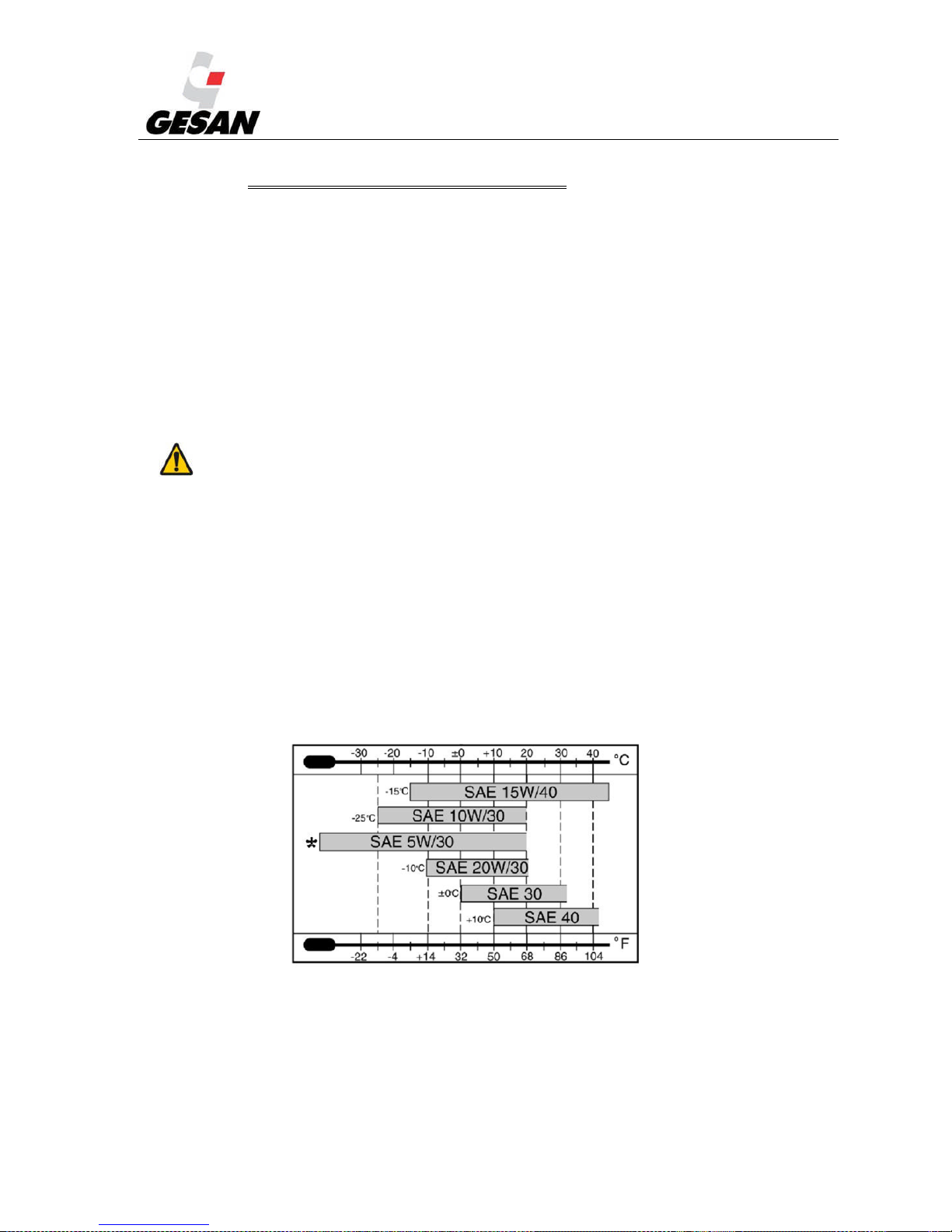
For temperature condicitons diferent from indicated, choose the fuel type according to the following table:
Figure 24 - Recommended types of oil as a function of temperature
Page 58
STANDBY GENERATOR SETS V-6.4
57
2) The Engine oil level shall also be checked periodically. This will be accomplished by
pulling out the dipstick. It shall be carried out with the engine cold and in a horizontal position. If
you wish to check the oil level upon shutting down the Engine, wait for the housing to drain prior
to checking the oil level.
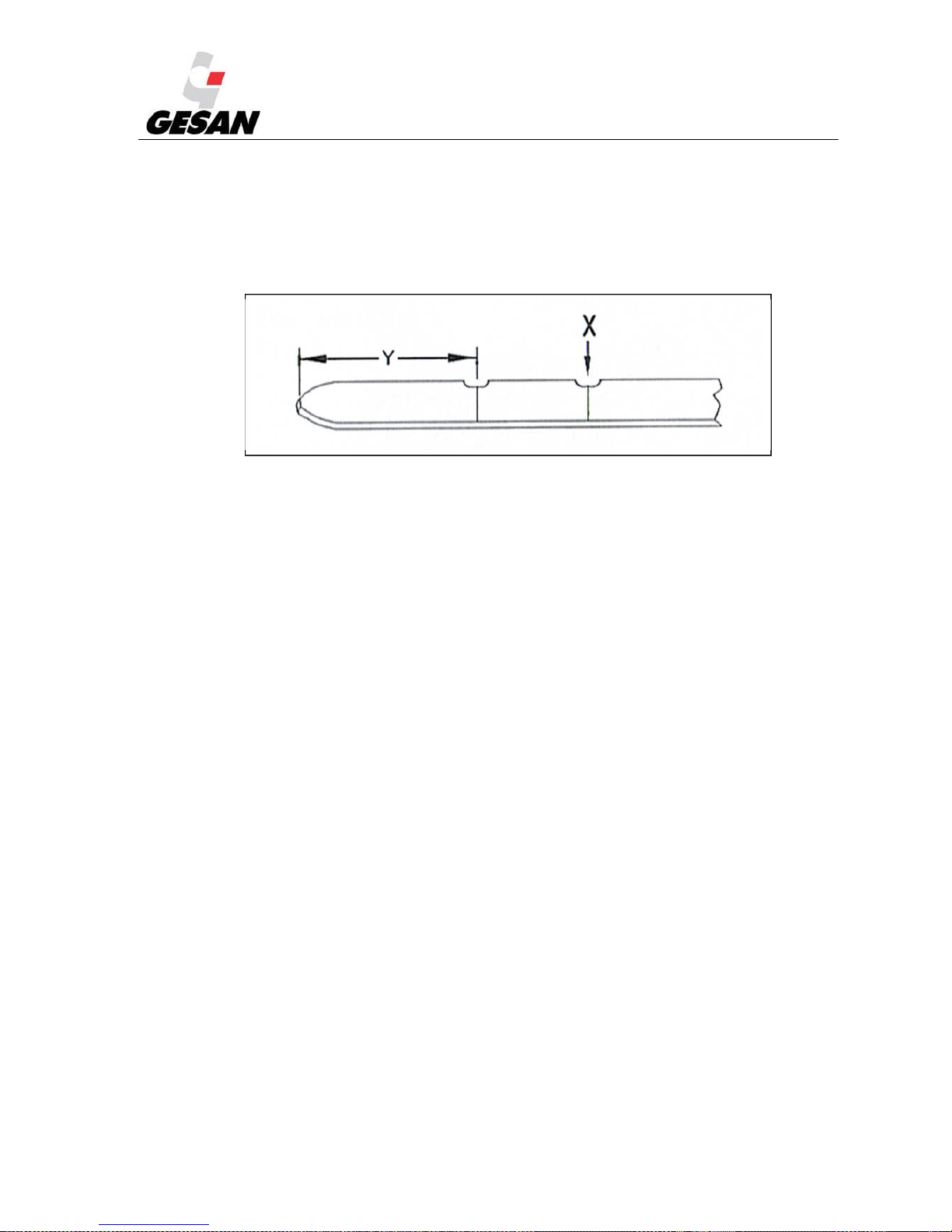
Image 25-Oil level dipstick.
The dipstick has two markings; a minimum oil level marking (Y) and a maximum oil level
marking (X). The recommended service level is between both markings.
If the oil level is below the minimum, the engine oil must be serviced. However, the oil level
shall never exceed the maximum level.
Unscrew the Engine’s oil filler plug; completely remove the plug in order to have free access to
the oil tank. Once serviced with oil, clean the oil tank cover and reinstall the oil filler plug. If the
engine oil must be replaced, first the engine oil must be drained. To accomplish this, the generator
set may include an external connection with a plug, from which the engine oil can be drained;
otherwise, the generator set must be opened and the engine oil shall be drained through the lower
plug located under the engine housing (refer to the engine manual delivered separately). Once the
engine oil is drained, re-install the plug that was removed and service the engine oil as indicated
for checking the oil level (refer to the engine manual, which is delivered separately for this task).
Take into account the capacity of the tank where the used fluid is going to be poured and be
careful not to spill any fluid. Remember that the fluid is hazardous to the environment. Adopt the
necessary protective measures for handling the fluid; especially the use of protective goggles. If
fluid comes in contact with the skin, immediately wash the affected area.
Page 59

STANDBY GENERATOR SETS V-6.4
58
3) The radiator coolant level should be adequate.
4) The fuel level in the tank should be sufficient for the service to be performed. In the
DEEP SEA 4420 generator control panel is equipped with a fuel gauge, which will be functional
whenever the electrical panel is receiving power. The generator set’s fuel tank incorporates a
lower plug to drain the tank if required. Be careful to not spill fuel when carrying out this task and
adopt the necessary protective measures for handling fuel; especially the use of protective goggles.
If fuel comes in contact with the skin, immediately wash the affected area.
5) Always refuel in a well ventilated area with the engine stopped.
6) Closely inspect the connections and the electrical circuit, for both the mechanical and
electrical sections.
7) Check carefully for possible liquid leaks. If a leak is detected, find its source and resolve
the problem. If your unit has a retention bath, drain it (see section 3.4 RETENTION BATH).
8) The air inlet and outlet vents should be completely unobstructed to allow for free
circulation of cooling air.
9) Check the state of the unit’s radiator and clean if necessary. The Engine cooling fluid
levels shall be checked periodically, and shall be serviced if found below the minimum. The
cooling fluid used will be 50% ethylene glycol with a corrosion inhibitor (BS 658: 1992 or MOD
AL39) and 50% distilled water. To drain the engine cooling circuit, depending on the model, the
generator set may incorporate an external connection with a drain plug for that circuit; otherwise,
the draining must be carried out through the bottom part of the radiator. Servicing with coolant
once the circuit has been drained will be accomplished through the top part of the radiator, through
the radiator’s top plug, which is accessible through the covered openings arranged on the generator
set’s fairing. Take into account the capacity of the tank where the used fluid is going to be poured
and be careful not to spill any fluid. Remember that the fluid is hazardous to the environment.
Adopt the necessary protective measures for handling the fluid; especially the use of protective
goggles. If fluid comes in contact with the skin, immediately wash the affected area.
For further information, refer to the engine manual, which is delivered separately.
10) Make sure the exhaust tube is not obstructed.
11) Check the battery’s connection terminals and electrolyte level (if necessary, add
demineralized or distilled water). Acid should never be added. The battery should be recharged if
the terminal voltage is below 12.3 V.
12) If the battery needs recharging after being taken out of the unit, remove the vent caps and
charge battery with direct current only. Connect the charger’s positive (+) cable to the battery’s
positive (+) terminal and the charger’s negative (-) cable to the battery’s negative (-) terminal.
Recharge battery with a current equivalent to 1/10 the rated capacity (Ah). Battery is fully charged
Page 60

STANDBY GENERATOR SETS V-6.4
59
when acid density is 1.28. Before completing recharging process: turn off charger before
disconnecting battery and check electrolyte level.
13) If the battery is discharged and you want to perform an emergency startup with the battery
from another generator, first check the tightness of the discharged battery’s terminals. Stop the
engines of both units and connect the two positive terminals of the batteries first and then connect
the negative terminal of the charged battery to a metal area on the disabled unit (ground). Start up
the auxiliary unit and then the unit being repaired. Disconnect the cables in reverse order to avoid
a short circuit. Finally, fully charge the battery.
While performing preventive maintenance tasks it is advisable to wear protective eyewear and gloves during all operations
involving the handling of battery acid. Make sure there is nearby access to tap water in order to wash all potentially affected areas.
Remember to always perform all operations with the utmost precaution and safety as indicated in this Manual. (Pay
special attention to the risk of short circuits that could be caused by coming in contact with the unit’s metallic objects.)
Page 61

STANDBY GENERATOR SETS V-6.4
60
7.3. MAINTENANCE CHART
FREQUENCY MAINTENANCE OPERATION
MONTHLY
Perform a mains failure simulation; the unit should supply power to consumers for
one hour.
For parallel units, check the connection and the load sharing.
Review the connections of the startup battery, clean and cover with vaseline.
Make sure the battery charger is functioning properly.
Make sure fuel pump is functioning properly.
Check fuel level on the main fuel tank.
Check coolant and oil levels.
Make sure smoke extractor is functioning properly.
Make sure all of the electrical panel lights are functioning properly.
Make sure the ATS functions properly in transfers.
Check the state of all of the gauges and indicators on the electrical panel.
Check the engine manufacturer's manual for specific tasks.
EVERY 6
MONTHS
Start up the engine manually three times, noting each time the voltage and density
readings for each of the battery’s elements. If any of the voltage readings varies
significantly from those of the battery’s other elements, do not perform the remaining
manual engine startups.
Fully charge the battery and check the electrolyte level.
Make sure there are no leaks in the coolant tubes.
Make sure that all of the unit’s alarms display correctly.
Check the engine manufacturer's manual for specific tasks.
YEARLY
Clean the outside of the fuel tank and check the diesel pipes.
Clean radiator, change antifreeze.
Clean and lube the water pump and fan.
Make sure meters are correct.
Clean control panel and tighten the panel’s connections.
Verify that the antivibration feet, fittings and belts are in proper condition.
Make sure that vibration and noise levels comply with the current regulations.
Make sure noise emission level is compliant with the current regulations.
Check the engine manufacturer's manual for specific tasks.
In case you had a soundproofed group, clean and grease the lock of the access and
panel door.
EVERY 3
YEARS
Replace startup batteries.
Page 62
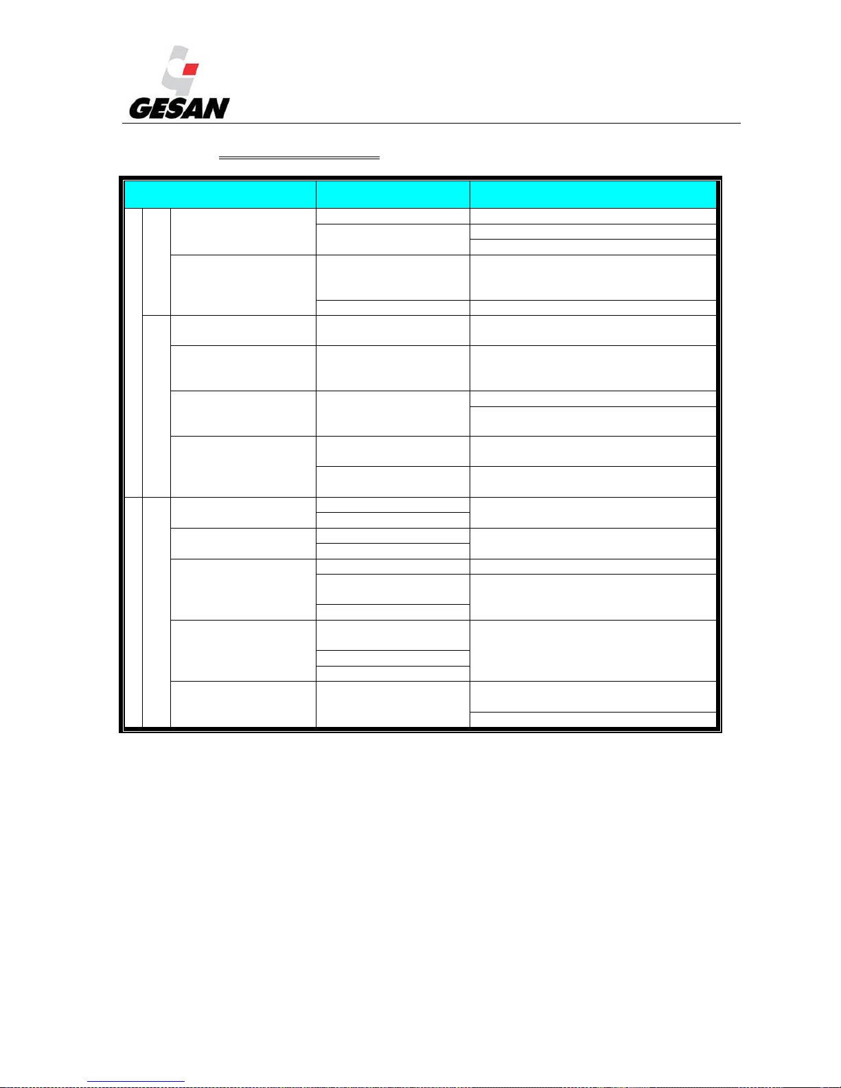
STANDBY GENERATOR SETS V-6.4
61
8. TROUBLESHOOTING
INCIDENT LIKELY CAUSE SOLUTION
In the electrical panel
Engine
does not start
Starter does not
turn
1.-Defective battery 1.-Replace battery
2.-Defective starting
system
2.-Replace starting system
3.-Contact technical service.
Starter functioning
properly
1.-Faulty voltage
detector on control
module
1.-Contact technical service.
2.-Low fuel level 2.-Refill fuel tank
Engine starts
Stops with cause
1.-Emergency has
occurred
1.-Take appropriate measures
Stops for no
apparent reason
1.-Emergency not
indicated due to faulty
LED indicator
1.-Contact technical service.
Does not stop
when emergency
occurs
1.-Defective
stopping system
1.-Press emergency stop button
2.-Contact technical service.
Generator does not
stop when in stop
position
1.-Faulty control
unit
1.-Press emergency stop button
2.-Defective
Stopping System
2.-Contact technical service.
Originating in engine’s interior
Unit in operation
High voltage at no
load
1.-Overspeed
1.-Contact technical service.
2.-Alternator failure
Low voltage at no
load
1.-Underspeed
1.-Contact technical service.
2.-Alternator failure
Correct voltage but
low when on load
1.-Heavy load 1.-Reduce power of loads
2.-Underspeed on
load
2.-Contact technical service.
3.-Alternator failure
Voltage unstable
1.-Voltage meter
damaged
1.-Contact technical service.
2.-Engine unsteady
3.-AVR damaged
Strange noise
inside the unit
1.-Various causes
1.-Make sure nothing is preventing the
unit from functioning properly.
2.-Contact technical service.
Page 63

STANDBY GENERATOR SETS V-6.4
62
9. PROTECTION FROM THE ENVIRONMENT
Once the generator set has been installed, it is necessary to remove the packaging, accessories, electrical
tools, etc., that were used during the installation process.
When it is time to dispose of the batteries, in keeping with environmental regulations it is advisable to
take them to an authorized recycling center.
For a cleaner environment, recycle all possible items and be sure to not throw electrical components in
with the regular garbage so as to comply with European directive 2002/96/EC. These items should be
stored separately until being taken for ecological recycling.
10. WARRANTY
The warranty of the generator set is extended for a calendar year from the date it is commissioned.
This must be reported to GRUPOS ELECTRÓGENOS EUROPA S.A., (hereafter the manufacturer)
in writing, whether by fax, or e-mail. The data that must be communicated is the MODEL NUMBER,
SERIAL NUMBER AND COMMISSIONING DATE.
If the manufacturer is not notified of the commissioning within a maximum period of sixty days
from the invoice date, then the invoice date itself will be used as the effective start date of the
warranty period. If for any reason the commissioning cannot be performed in the sixty days following
the invoice date, the manufacturer must be informed of this in writing. This extension of the warranty
is subject to the acceptance of the end supplier of the engine and alternator. This shall never exceed
120 days from the invoice date. This acceptance shall be sent by staff of GRUPOS ELECTRÓGENOS
EUROPA S.A.
The warranty covers defects in components and assembly, not due to improper use, manipulation,
modification or insufficient maintenance. The warranty does not cover failures caused by use of the
generator set with other devices that have not been installed or supplied by the manufacturer. Also
excluded are any failures and damages caused by prolonged or improper storage. In this last case,
refer to the manufacturer’s user manuals.
The warranty for the generator set ONLY covers spare parts and labor required for operating the
set by personnel authorized by the manufacturer. Travel, and other expenditures derived from the
repairing of a set under warranty are excluded from the warranty coverage therefore, under no
circumstance shall the manufacturer cover these expenses, which must be paid for in full.
The decision to accept or deny a warranty claim will be made by the manufacturer. Regarding
engine and alternator failures, the warranty will be granted by the supplier of these components in
accordance with their warranty conditions. The manufacturer reserves the right to require that the
faulty component be returned to them. In this case, all expenses arising from this recovery shall be
covered by the customer until the resolution of the warranty. If the warranty is accepted, the transport
costs of this return shall be paid provided the cost is not greater than that caused by shipping the
material in advance.
Page 64

STANDBY GENERATOR SETS V-6.4
63
Any repair made within the warranty period shall not lead to the modification of expiry date for
the generator set warranty.
The warranty does not cover damages caused by terrorist acts, natural disasters, sabotages or
similar occurrences.
If any of the stated provisions does not comply with the legislation of a specific country, the
importer is required to notify the manufacturer prior to executing the purchasing-sale operation.
This warranty expressly replaces all other warranties, explicit or implicit, including any warranty
that is commercial or suitable for personal use. The warranty presented here is for exclusive use in
resolving claims based on defects and non-conformities in generator sets, regardless of whether the
claim is based on a contract or grievance, and replaces other resolutions, responsibilities or rights,
whether or not they arise by law.
11. NOISE LEVEL
Generator sets manufactured by GRUPOS ELECTRÓGENOS EUROPA S.A. produce different acoustic
levels depending on the output and soundproofing of the generator set. The noise output is indicated on a
sticker affixed to the unit’s base frame.
Note: If you work near the unit for any extended period of time, it is advisable to use hearing protection.
12. DECLARATION OF CONFORMITY
GRUPOS ELECTRÓGENOS EUROPA S.A., shall deliver a CE “declaration of conformity” form along
with the unit, in compliance with the referenced regulations or standardized documents.
Page 65
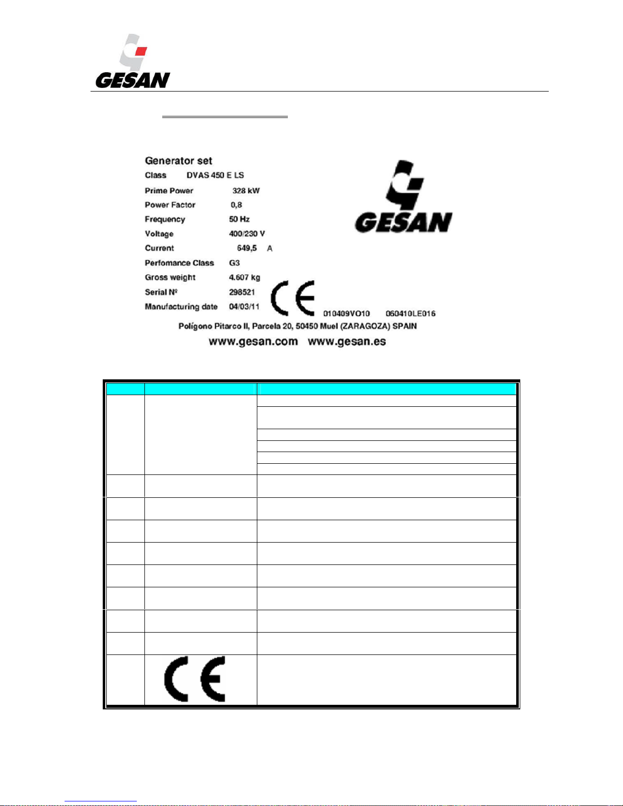
STANDBY GENERATOR SETS V-6.4
64
13. APPENDIX 1: FIGURES
Detail of the unit’s Identification Label:
Image 26- Identification Label
# LABELED ITEM DESCRIPTION
(
1)
DVAS 450 E
D => Engine uses Diesel fuel at 1500/1800 rpm
V => Engine manufacturer is (V)olvo, (P)erkins,
(C)ummins, Mitsubis(H)I or M(T)U.
A => The generator set is automatic
S => The generator set is soundproofed
450 => Commercial name
E => Indicates generator set is standby type
(
2)
Rated power Rated power of generator set expressed in kW.
(
3)
Power factor Indicates power factor of generator set
(
4)
Rated frequency Rated frequency of generator set (Hertz)
(
5)
Rated voltage Rated voltage of generator set (Volts)
(
6)
Product class
When withstanding a load, engine will perform according
to catalogued response times per ISO 8528
(
7)
Weight Total weight of generator set
(
8)
Serial no. Serial number of generator manufacture
(
9)
Manufacture date Manufacture date of generator set
(
10)
CE marking indicates that generator set complies with the
relevant directives
Page 66
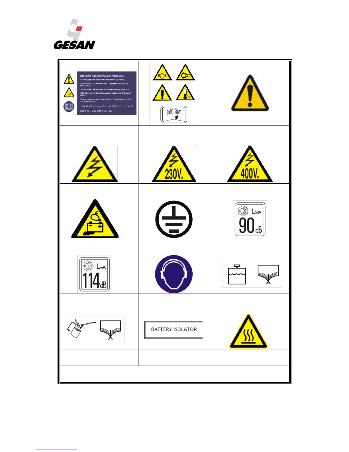
STANDBY GENERATOR SETS V-6.4
65
Image 27:This genset may
start without prior warning
Image 28:General warning
Image 29:Undefined
warning notice
Image 30: Electrical hazard
Image 31: Electrical
hazard 230 Volts
Image 32: Electrical
hazard 400 Volts
Image 33: Possible spillage
of battery acid
Image 34:Electrical
grounding
Image 35:Noise output
90 dB
Image 36: Noise output
114 dB
Image 37: Mandatory
hearing protection.
Image 38: Coolant flush
Image 39: Oil flush Image 40: Battery isolator
Image 41:High
temperature
On hot surfaces where it has not been possible to minimize the risk of burns, the following warning
pictogram will be installed.
Page 67

STANDBY GENERATOR SETS V-6.4
66
14. APPENDIX 2: IMAGE INDEX
Image 1- Generator set with sound proof canopy................................................................................................... 6
Image 2- Generator set without canopy.................................................................................................................. 6
Image 3- Detailed view of Insonorized genset ........................................................................................................ 7
Image 4- Detailed view of openskid genset............................................................................................................. 9
Image 5- Noise output pictograms and hearing protection required................................................................... 11
Image 7-Control panel with InteliGen
N T
module................................................................................................. 13
Image 8-Control panel with DEEP SEA Control module ..................................................................................... 14
Image 9- Load Transfer diagram.......................................................................................................................... 15
Image 10- Retention Bath...................................................................................................................................... 16
Image 11- Lifting frame ........................................................................................................................................ 17
Image 12- Detailed view of installation of an open-skid unit................................................................................ 18
Image 13- SAB-BE Pump...................................................................................................................................... 19
Image 14- Connecting external power input......................................................................................................... 23
Image 15- ATS setup ............................................................................................................................................. 24
Image 16- Diagram of ATS Panel......................................................................................................................... 25
Image 17- Diagram of ATS Panel by motorized contactors.................................................................................. 26
Image 18- Lateral power cables trapdoor entry................................................................................................... 29
Image 19- Power cables entry by bedplate ........................................................................................................... 29
Image 22- Deep Sea 7310 Control Module........................................................................................................... 39
Image 23- INTELIGENNTDigital Control Module............................................................................................... 50
Image 23-Oil level dipstick. .................................................................................................................................. 57
Image 27:This genset may start without prior warning ........................................................................................ 65
Image 28:General warning................................................................................................................................... 65
Image 29:Undefined warning notice..................................................................................................................... 65
Image 30: Electrical hazard.................................................................................................................................. 65
Image 31: Electrical hazard 230 Volts ................................................................................................................. 65
Image 32: Electrical hazard 400 Volts ................................................................................................................. 65
Image 33: Possible spillage of battery acid .......................................................................................................... 65
Image 34:Electrical grounding............................................................................................................................. 65
Image 35:Noise output 90 dB................................................................................................................................ 65
Image 36: Noise output 114 dB............................................................................................................................. 65
Image 37: Mandatory hearing protection............................................................................................................. 65
Image 38: Coolant flush........................................................................................................................................ 65
Image 39: Oil flush ............................................................................................................................................... 65
Image 40: Battery isolator .................................................................................................................................... 65
Image 41:High temperature.................................................................................................................................. 65
Page 68

STANDBY GENERATOR SETS V-6.4
67
15. APPENDIX 3: PRE-DELIVERY INSPECTION DOCUMENT
Page 69
STANDBY GENERATOR SETS V-6.4
68
16. APPENDIX 4: DERATING OF ENGINE POWER RATING:
Engine power rating is declared for the following conditions in accordance with
the norms ISO-8528-1:2005 and ISO-3046-1:2002.
- Air pressure: 100 kPa
- Temperature: 25ºC
- Relative humidity: 30%
If site ambient conditions are different from standard, derating of engine power
rating is possible.
This derating depends on the characteristics of every engine. Please consult those
derating in his technical sheets.
According to norm ISO-3046-1:2002, the derating of engine power rating could be
found are:
16.1. DERATING OF POWER RATING OF TTURBOCHARGED
ENGINES WITHOUT CHARGE AIR COOLING:
Altitude from sea Barometric pressure Temperature (ºC)
m kPa
-10 0 5 10 15 20 25 30 35 40 45 50
0 101,3 1,33 1,23 1,18 1,13 1,09 1,05 1,01 0,97 0,94 0,90 0,87 0,84
100 100,1 1,32 1,22 1,17 1,12 1,08 1,04 1,00 0,96 0,93 0,90 0,86 0,83
200 99,5 1,31 1,21 1,16 1,12 1,08 1,03 1,00 0,96 0,92 0,89 0,86 0,83
300 98,7 1,31 1,20 1,16 1,11 1,07 1,03 0,99 0,95 0,92 0,89 0,85 0,82
400 96,7 1,29 1,18 1,14 1,09 1,05 1,01 0,97 0,94 0,90 0,87 0,84 0,81
500 95,5 1,27 1,17 1,13 1,08 1,04 1,00 0,96 0,93 0,89 0,86 0,83 0,80
600 94,4 1,26 1,16 1,12 1,07 1,03 0,99 0,96 0,92 0,89 0,85 0,82 0,79
700 93,2 1,25 1,15 1,11 1,06 1,02 0,98 0,95 0,91 0,88 0,85 0,82 0,79
800 92,1 1,24 1,14 1,10 1,05 1,01 0,97 0,94 0,90 0,87 0,84 0,81 0,78
900 90,9 1,23 1,13 1,08 1,04 1,00 0,96 0,93 0,89 0,86 0,83 0,80 0,77
1000 89,9 1,22 1,12 1,07 1,03 0,99 0,96 0,92 0,88 0,85 0,82 0,79 0,76
1100 88,8 1,20 1,11 1,06 1,02 0,98 0,95 0,91 0,88 0,84 0,81 0,78 0,76
1200 87,7 1,19 1,10 1,05 1,01 0,97 0,94 0,90 0,87 0,84 0,80 0,78 0,75
1300 86,7 1,18 1,09 1,04 1,00 0,96 0,93 0,89 0,86 0,83 0,80 0,77 0,74
1400 85,6 1,17 1,08 1,03 0,99 0,96 0,92 0,88 0,85 0,82 0,79 0,76 0,73
1500 84,5 1,16 1,07 1,02 0,98 0,95 0,91 0,87 0,84 0,81 0,78 0,75 0,73
1600 83,5 1,15 1,06 1,01 0,97 0,94 0,90 0,87 0,83 0,80 0,77 0,75 0,72
1700 82,4 1,14 1,05 1,00 0,96 0,93 0,89 0,86 0,82 0,79 0,77 0,74 0,71
1800 81,5 1,13 1,04 1,00 0,96 0,92 0,88 0,85 0,82 0,79 0,76 0,73 0,70
1900 80,5 1,12 1,03 0,99 0,95 0,91 0,87 0,84 0,81 0,78 0,75 0,72 0,70
2000 79,5 1,11 1,02 0,98 0,94 0,90 0,87 0,83 0,80 0,77 0,74 0,72 0,69
2200 77,6 1,08 1,00 0,96 0,92 0,88 0,85 0,82 0,79 0,76 0,73 0,70 0,68
2400 75,6 1,06 0,98 0,94 0,90 0,87 0,83 0,80 0,77 0,74 0,71 0,69 0,66
2600 73,7 1,04 0,96 0,92 0,88 0,85 0,81 0,78 0,75 0,73 0,70 0,67 0,65
2800 71,9 1,02 0,94 0,90 0,86 0,83 0,80 0,77 0,74 0,71 0,68 0,66 0,63
3000 70,1 1,00 0,92 0,88 0,85 0,81 0,78 0,75 0,72 0,70 0,67 0,64 0,62
3200 68,4 0,98 0,90 0,87 0,83 0,80 0,77 0,74 0,71 0,68 0,66 0,63 0,61
3400 66,7 0,96 0,88 0,85 0,81 0,78 0,75 0,72 0,69 0,67 0,64 0,62 0,60
3600 64,9 0,94 0,87 0,83 0,80 0,76 0,73 0,71 0,68 0,65 0,63 0,60 0,58
3800 63,2 0,92 0,85 0,81 0,78 0,75 0,72 0,69 0,66 0,64 0,61 0,59 0,57
4000 61,6 0,90 0,83 0,80 0,76 0,73 0,70 0,68 0,65 0,62 0,60 0,58 0,56
Note: Environmental conditions of T=298 K y P=100 kPa.
In order to know the particular engine power rating derating, refer to manufacturer technical specifications.
Page 70

STANDBY GENERATOR SETS V-6.4
69
16.2. DERATING OF ENGINE POWER RATING OF
TURBOCHARGED ENGINES WITH CHARGE AIR COOLING:
Altitude from sea Barometric pressure Temperature (ºC)
m kPa -10 0 5 10 15 20 25 30 35 40 45 50
0 101,3 1,28 1,22 1,19 1,16 1,13 1,11 1,08 1,06 1,04 1,01 0,99 0,97
100 100,1 1,27 1,21 1,18 1,15 1,12 1,10 1,07 1,05 1,03 1,00 0,98 0,96
200 99,5 1,26 1,20 1,17 1,14 1,12 1,09 1,07 1,04 1,02 1,00 0,98 0,96
300 98,7 1,25 1,19 1,16 1,14 1,11 1,09 1,06 1,04 1,02 0,99 0,97 0,95
400 96,7 1,23 1,17 1,15 1,12 1,09 1,07 1,04 1,02 1,00 0,98 0,96 0,94
500 95,5 1,22 1,16 1,13 1,11 1,08 1,06 1,03 1,01 0,99 0,97 0,95 0,93
600 94,4 1,21 1,15 1,12 1,10 1,07 1,05 1,02 1,00 0,98 0,96 0,94 0,92
700 93,2 1,20 1,14 1,11 1,09 1,06 1,04 1,01 0,99 0,97 0,95 0,93 0,91
800 92,1 1,19 1,13 1,10 1,08 1,05 1,03 1,01 0,98 0,96 0,94 0,92 0,90
900 90,9 1,18 1,12 1,09 1,07 1,04 1,02 0,99 0,97 0,95 0,93 0,91 0,89
1000 89,9 1,17 1,11 1,08 1,06 1,03 1,01 0,99 0,96 0,94 0,92 0,90 0,88
1100 88,8 1,15 1,10 1,07 1,05 1,02 1,00 0,98 0,96 0,93 0,91 0,89 0,88
1200 87,7 1,14 1,09 1,06 1,04 1,01 0,99 0,97 0,95 0,92 0,90 0,89 0,87
1300 86,7 1,13 1,08 1,05 1,03 1,00 0,98 0,96 0,94 0,92 0,90 0,88 0,86
1400 85,6 1,12 1,07 1,04 1,02 0,99 0,97 0,95 0,93 0,91 0,89 0,87 0,85
1500 84,5 1,11 1,06 1,03 1,01 0,98 0,96 0,94 0,92 0,90 0,88 0,86 0,84
1600 83,5 1,10 1,05 1,02 1,00 0,97 0,95 0,93 0,91 0,89 0,87 0,85 0,83
1700 82,4 1,09 1,04 1,01 0,99 0,96 0,94 0,92 0,90 0,88 0,86 0,84 0,82
1800 81,5 1,08 1,03 1,00 0,98 0,96 0,93 0,91 0,89 0,87 0,85 0,83 0,82
1900 80,5 1,07 1,02 0,99 0,97 0,95 0,92 0,90 0,88 0,86 0,84 0,83 0,81
2000 79,5 1,06 1,01 0,98 0,96 0,94 0,92 0,89 0,87 0,86 0,84 0,82 0,80
2200 77,6 1,04 0,99 0,96 0,94 0,92 0,90 0,88 0,86 0,84 0,82 0,80 0,79
2400 75,6 1,02 0,97 0,95 0,92 0,90 0,88 0,86 0,84 0,82 0,80 0,79 0,77
2600 73,7 1,00 0,95 0,93 0,90 0,88 0,86 0,84 0,82 0,80 0,79 0,77 0,75
2800 71,9 0,98 0,93 0,91 0,89 0,87 0,85 0,83 0,81 0,79 0,77 0,75 0,74
3000 70,1 0,96 0,91 0,89 0,87 0,85 0,83 0,81 0,79 0,77 0,76 0,74 0,72
3200 68,4 0,94 0,89 0,87 0,85 0,83 0,81 0,79 0,77 0,76 0,74 0,72 0,71
3400 66,7 0,92 0,88 0,86 0,83 0,81 0,80 0,78 0,76 0,74 0,73 0,71 0,69
3600 64,9 0,90 0,86 0,84 0,82 0,80 0,78 0,76 0,74 0,73 0,71 0,69 0,68
3800 63,2 0,88 0,84 0,82 0,80 0,78 0,76 0,74 0,73 0,71 0,69 0,68 0,66
4000 61,6 0,87 0,82 0,80 0,78 0,76 0,75 0,73 0,71 0,70 0,68 0,66 0,65
Note: Environmental conditions of T=298 K y P=100 kPa.
Intercooler reference conditions: T=330 K, Tc=300 K y P=70 kPa.
In order to know the particular engine power rating derating, refer to manufacturer technical
specifications.
Page 71
STANDBY GENERATOR SETS V-6.4
70
16.3. DERATING OF ENGINE POWER RATING OF NATURALY
ASPIRED ENGINES:
Altitude from sea Barometric pressure
Humidity: 30%
Temperature (ºC)
-10 0 5 10 15 20 25 30 35 40 45
0 101,30 1,14 1,10 1,09 1,07 1,05 1,03 1,02 1,00 0,98 0,97 0,95
100 100,00 1,12 1,09 1,07 1,05 1,03 1,02 1,00 0,98 0,97 0,95 0,93
200 98,90 1,11 1,07 1,05 1,04 1,02 1,00 0,99 0,97 0,95 0,94 0,92
400 96,70 1,08 1,04 1,03 1,01 0,99 0,98 0,96 0,94 0,93 0,91 0,90
600 94,40 1,05 1,01 1,00 0,98 0,96 0,95 0,93 0,92 0,90 0,88 0,87
800 92,10 1,02 0,98 0,97 0,95 0,93 0,92 0,90 0,89 0,87 0,86 0,84
1000 89,90 0,99 0,95 0,94 0,92 0,91 0,89 0,88 0,86 0,85 0,83 0,82
1200 87,70 0,96 0,92 0,91 0,89 0,88 0,86 0,85 0,83 0,82 0,80 0,79
1400 85,60 0,93 0,90 0,88 0,87 0,85 0,84 0,82 0,81 0,79 0,78 0,76
1600 83,50 0,90 0,87 0,85 0,84 0,82 0,81 0,80 0,78 0,77 0,75 0,74
1800 81,50 0,87 0,84 0,83 0,81 0,80 0,79 0,77 0,76 0,74 0,73 0,72
2000 79,50 0,85 0,82 0,80 0,79 0,77 0,76 0,75 0,73 0,72 0,71 0,69
2200 77,60 0,82 0,79 0,78 0,76 0,75 0,74 0,72 0,71 0,70 0,68 0,67
2400 75,60 0,79 0,76 0,75 0,74 0,72 0,71 0,70 0,69 0,67 0,66 0,65
2600 73,70 0,77 0,74 0,73 0,71 0,70 0,69 0,67 0,66 0,65 0,64 0,62
2800 71,90 0,74 0,72 0,70 0,69 0,68 0,66 0,65 0,64 0,63 0,62 0,60
3000 70,10 0,72 0,69 0,68 0,67 0,65 0,64 0,63 0,62 0,61 0,59 0,58
3200 68,40 0,70 0,67 0,66 0,64 0,63 0,62 0,61 0,60 0,59 0,57 0,56
3400 66,70 0,67 0,65 0,63 0,62 0,61 0,60 0,59 0,58 0,57 0,55 0,54
3600 64,90 0,65 0,62 0,61 0,60 0,59 0,58 0,57 0,55 0,54 0,53 0,52
3800 63,20 0,62 0,60 0,59 0,58 0,57 0,56 0,55 0,53 0,52 0,51 0,50
4000 61,50 0,60 0,58 0,57 0,56 0,55 0,53 0,52 0,51 0,50 0,49 0,48
Note: Environmental conditions of T=298 K y P=100 kPa. Relative humidity 30%
In order to know the particular engine power rating derating, refer to manufacturer technical
specifications.
Page 72

STANDBY GENERATOR SETS V-6.4
71
NOTAS:
Page 73

STANDBY GENERATOR SETS V-6.4
72
Page 74

STANDBY GENERATOR SETS V-6.4
73
Page 75

STANDBY GENERATOR SETS V-6.4
74
Page 76
*RUPOS ELECTRÓGENOS EUROPA, S.A.
3ROtJRQR,QGXVWULDO3LWDUFR,,QDYH
7HOpIRQR)D[
08(/=DUDJR]D63$,1
ZZZJHVDQFRPH[SRUW#JHVDQFRPLQIR#JHVDQFRP
V6.4
 Loading...