

Page 1
Page 2

RENTAL & SILENT ENERGY RENTAL GENSETS 4.4
1
Contenido
1 WELCOME............................................................................................................................................3
2 BASIC SAFETY RULES.......................................................................................................................4
3 DESCRIPTION OF THE GENERATOR SET ......................................................................................6
3.1. SOUND INSULATION ...................................................................................................................8
3.2. CONTROL UNITS...........................................................................................................................9
3.1.1. DEEP SEA digital control plate.......................................................................................10
3.1.2. INTELIGEN digital control plate ....................................................................................11
3.2. TRAILER .......................................................................................................................................12
3.3. LIQUID COLLECTION TRAY.....................................................................................................14
4. INSTALLATION OF THE GENERATOR SET .................................................................................15
4.1. UNLOADING AND TRANSPORT...............................................................................................15
4.2. INSTALLATION OF MOBILE UNITS ........................................................................................17
4.2.1. Location...........................................................................................................................17
4.2.2. Fuel..................................................................................................................................17
4.2.3. Exhaust ............................................................................................................................19
4.2.4. Starting the generator set .................................................................................................19
4.2.5. Electrical connection........................................................................................................21
4.3. STORAGE......................................................................................................................................23
5. COMMISSIONING AND STOPPING................................................................................................24
5.1. GENERATOR SETS AND POWER FACTOR CORRECTORS..................................................24
5.2. OPERATION AT LOW LOAD IN DIESEL ENGINES................................................................25
6. OPERATION MANUAL .....................................................................................................................26
6.1. SWITCHBOARD COMPONENTS ...............................................................................................26
6.2. DEEP SEA 7310 CONTROL MODULE.......................................................................................29
6.3. INTELIGENNTDIGITAL CONTROL MODULE (OPTIONAL)..................................................40
7. MAINTENANCE OF THE GENERATOR SET.................................................................................46
7.1. BEFORE MAINTENANCE...........................................................................................................46
7.2. DURING MAINTENANCE...........................................................................................................46
7.3. MAINTENANCE TABLE .............................................................................................................49
8. SOLUTION OF BREAKDOWNS .......................................................................................................51
Page 3
RENTAL & SILENT ENERGY RENTAL GENSETS 4.4
2
9. PROTECTION OF THE ENVIRONMENT.........................................................................................51
10.WARRANTY .......................................................................................................................................52
11.NOISE LEVEL.....................................................................................................................................53
12.DECLARATION OF CONFORMITY ....................................................................................53
13.ANNEX 1: PICTOGRAMS..................................................................................................................54
14.ANNEX 2: SILENT-ENERGY RENTAL: ..........................................................................................56
14.1. DESCRIPTION OF THE GENERATOR SET....................................................................56
14.2. VARIATIONS IN THE ELECTRICAL CONFIGURATION: ...........................................57
14.3. VARIATIONS IN THE CONTROL INSTALLATION: .......................................58
14.3.1.Switchboard supplied by GRUPOS ELECTRÓGENOS EUROPA S.A .........................58
14.3.2.Switchboard not supplied by GRUPOS ELECTRÓGENOS EUROPA S.A...................59
14.3.3.“Emergency by signal” generator set:..............................................................................60
14.3.4.POWER installation: ..........................................................................................60
14.4. ATYS SWITCHES:.............................................................................................................60
14.5. ADDITIONAL COMPONENTS SUPPLIED WITH THE SILENT ENERGY RENTAL
UNITS: 61
14.5.1.DEEP SEA 7320 Digital Control MODULE...................................................................61
14.5.2.Lightning..........................................................................................................................72
14.5.3.Silent blocks in doors.......................................................................................................72
14.5.4.AVR in switchboard ........................................................................................................73
15.ANNEX 3: PICTURES INDEX:..........................................................................................................75
16.ANNEX 4: DERATING OF ENGINE POWER RATING: .................................................................76
16.1. DERATING OF POWER RATING OF TTURBOCHARGED ENGINES WITHOUT
CHARGE AIR COOLING:....................................................................................................................76
16.2. DERATING OF ENGINE POWER RATING OF TURBOCHARGED ENGINES WITH
CHARGE AIR COOLING:....................................................................................................................77
16.3. DERATING OF ENGINE POWER RATING OF NATURALY ASPIRED ENGINES:...78
1
Page 4

RENTAL & SILENT ENERGY RENTAL GENSETS 4.4
3
WELCOME
Thank you for acquiring a GESAN generator set.
The purpose of this manual is to describe the use and operation of the generator set, its components
and maintenance.
It is recommended that this manual be read carefully prior to working with the equipment for a
proper use.
Keep the document in case you need to refer to it and if the unit is resold, ensure this information
accompanies the generator set.
A general description of the unit and the necessary information for its installation, operation and
preventive maintenance can be found below.
In addition, you should have received a specific user manual for the engine and alternator, circuit
diagrams and set of keys.
If any problem is encountered with the supplied equipment please contact the distributor directly.
GRUPOS ELECTRÓGENOS EUROPA S.A, with the on-going aim of improving the product, will
revise its manuals to incorporate improvements made to the units supplied. For this reason the
information contained in this document may change without prior warning or obligation to update it.
Page 5

RENTAL & SILENT ENERGY RENTAL GENSETS 4.4
4
2 BASIC SAFETY RULES
Prior warnings and safety advice for handling the generator set supplied by GRUPOS
ELECTRÓGENOS EUROPA S.A
1) Do not allow unauthorised staff or minors without adult supervision to use the unit.
2) Use the necessary personal protective equipment.
3) Connect the machine to earth.
4) Ensure there is sufficient lighting on the control panel.
5) Do not install the generator set outdoors without its casing; there is a danger of electrocution and
breakdown.
6) It must be connected by a qualified electrician in accordance with the current standards and
regulations. A bad connection can cause the electric current to return leading to a risk of electrocution
for any person working with the grid.
7) The supply line from the generator set to the consumers must be protected by a switch with
differential protection against earth leakage.
8) Do not operate the unit with the doors open: risk of electrocution, burns or entrapment. Be sure the
doors are closed with keys before the start-up.
9) The exhaust system generates enough heat to ignite some materials. Therefore, never install the
generator set near flammable materials or near materials that may ignite easily or in locations where
the risk of a fire occurring is high.
10)Do not touch the engine or the exhaust while the generator set is running as it can cause severe burns.
11)Do not breathe the exhaust gases generated by the equipment.
12)Now how to stop the unit in case of emergency. Be special careful with his handling and storage.
13)For refuelling the engine, the generator set incorporates an exterior fuel filler neck and cap for filling
the tank with diesel. Never refuel with the engine running or in poorly ventilated areas; remember that
fuel vapours are toxic and flammable. Take the necessary safety precautions when handling fuel; the
use of gloves and safety goggles is recommended.
14)The fuel used is inflammable and volatile.
15)If you notice the generator set behaving abnormally, stop it immediately, locate, examine and resolve
the possible fault in the unit before starting it up again. Contact the technical services if required.
16)Keep the equipment separated at least one metre from buildings and other equipment.
Page 6

RENTAL & SILENT ENERGY RENTAL GENSETS 4.4
5
17)Be careful when replacing or installing a battery since it contains extremely hazardous acids. Avoid
spills and use protective equipment to avoid contact with the skin and eyes. In case of contact wash
with plenty of water and consult a doctor immediately.
18)In case of ingestion of battery acid, drink large quantities of water or milk and consult a doctor
immediately.
19)Use only distilled water in the battery as tap water shortens its service life.
20)If you exceed the maximum level when filling the battery the electrolyte will overflow. Clean it up
quickly to avoid the parts in contact with it corroding.
21)Frequently clean the equipment to prevent obstructions or the adherence of foreign objects (dust,
humidity, etc.).
22)Regularly inspect the unit’s electrical cables.
23)Engine oil is toxic and hazardous to the environment. Adopt the necessary safety measures when
handling engine oil. Prolonged exposure to used engine oil may cause skin cancer. Carefully wash
your hands after handling.
24)Prevent oil spills from occurring inside as well as outside the generator set. In the event of an oil
spillage inside the unit, clean it properly as it can be an inflammable material.
25)Do not fill the tank excessively. Ensure it is correctly closed. If there is a fuel spillage, take
precautions as the vapours and the fuel itself are inflammable. Properly clean the surroundings prior to
re-starting the equipment.
Page 7
RENTAL & SILENT ENERGY RENTAL GENSETS 4.4
6
3 DESCRIPTION OF THE GENERATOR SET
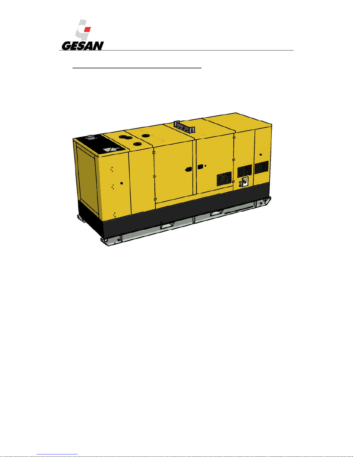
A general description of the generator set manufactured by GRUPOS ELECTRÓGENOS EUROPA
S.A (not identical to the genset supplied) and its different configurations can be found below.
Picture 1- Generator set with casing
Page 8
RENTAL & SILENT ENERGY RENTAL GENSETS 4.4
7
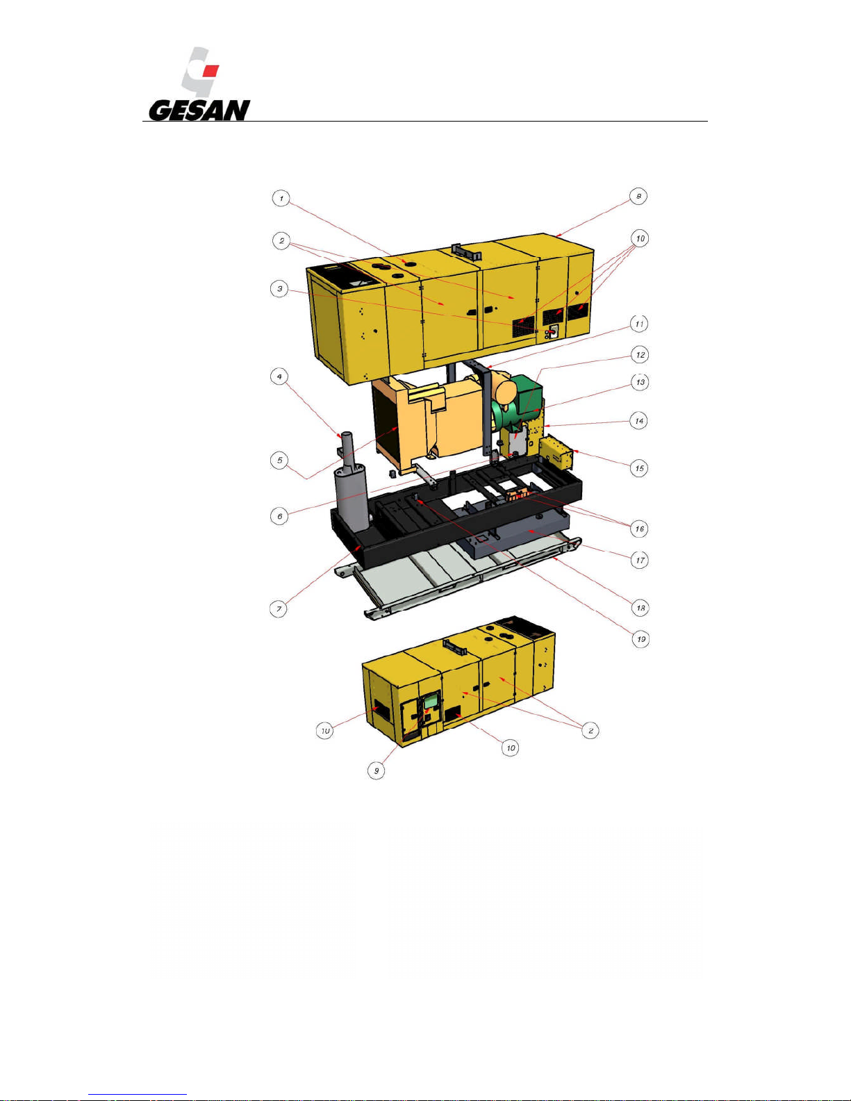
Picture 2- Exploded view of RENTAL soundproofed generator set
1) Coolant filler trap
2) Side access door
3) Fuel tank filler cap
4) Exhaust silencer
5) Engine
6) Antivibration mounts
7) Bedplate
8) Casing
9) Switch board door
10) Air inlet grilles
11) Elevationgantry and eyebolt
12) Power panel
13) Alternator
14) Power panel
15) RENTAL socket panel
16) Batteries
17) Fuel tank
18) Liquid collection tray
19) Sections supporting generator set on bedplate
20) Base support
Page 9
RENTAL & SILENT ENERGY RENTAL GENSETS 4.4
8
3.1. SOUND INSULATION
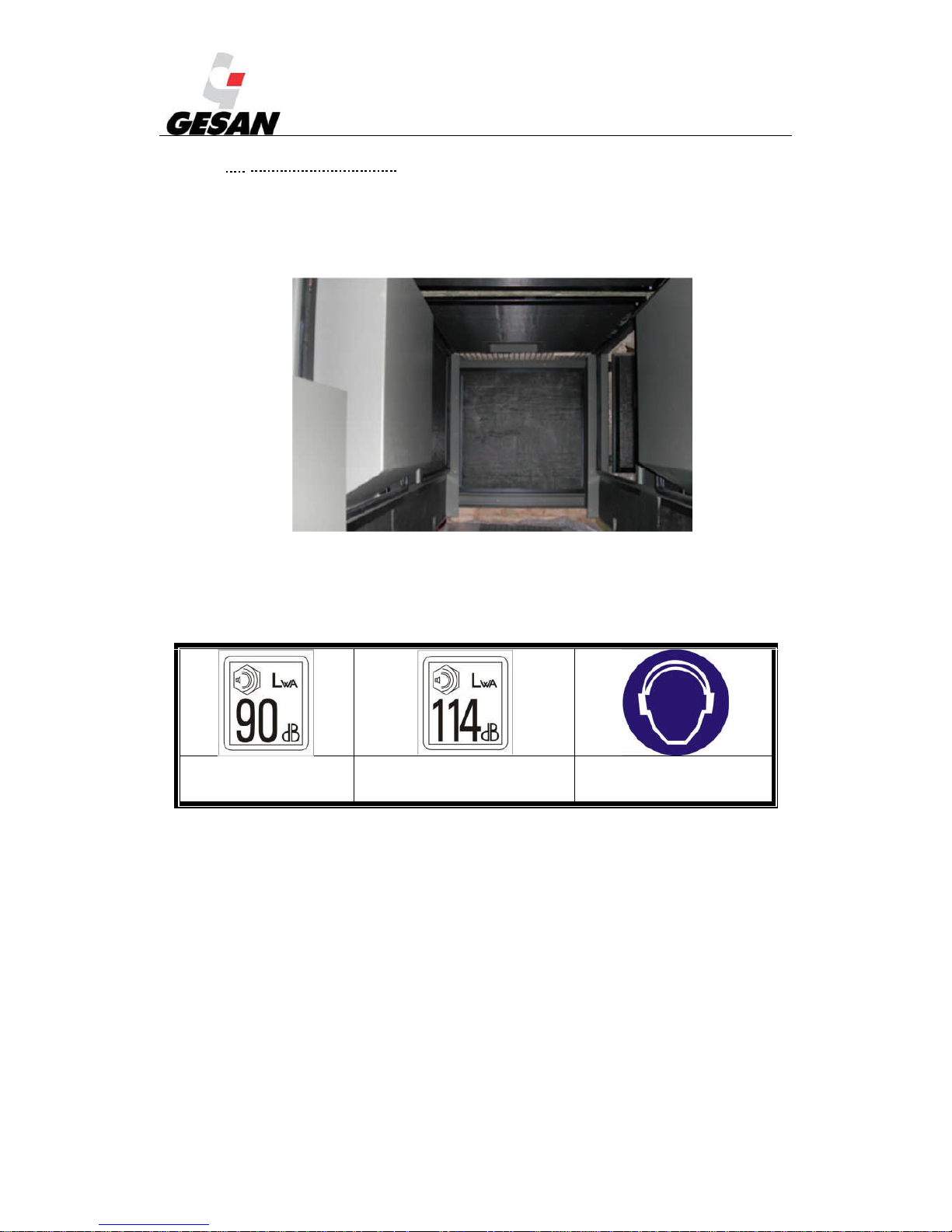
The unit supplied is soundproofed and its bodywork incorporates sound insulation. See point 11,
Noise level, for further information.
Picture 3-Inside a soundproofed generator set
Each generator set is supplied with a sticker indicating the level of acoustic power generated and
the need to use hearing protection.
Acoustic power 90 dBA Acoustic power 114 dBA Hearing protection must be worn.
Picture 4-Pictograms for acoustic power and compulsory hearing protection
The noise was measured according to European Directive 2000/14/CE and in compliance with the
maximum values determined by Directive 2005/88/CE.
Local standards that may be more restrictive must be taken into consideration. In all cases it is the
responsibility of the installer to comply with the current regulations.
Page 10
RENTAL & SILENT ENERGY RENTAL GENSETS 4.4
9
3.2. CONTROL UNITS
The unit supplied can be controlled from the different boards depending on the operation mode for
which it has been designed.
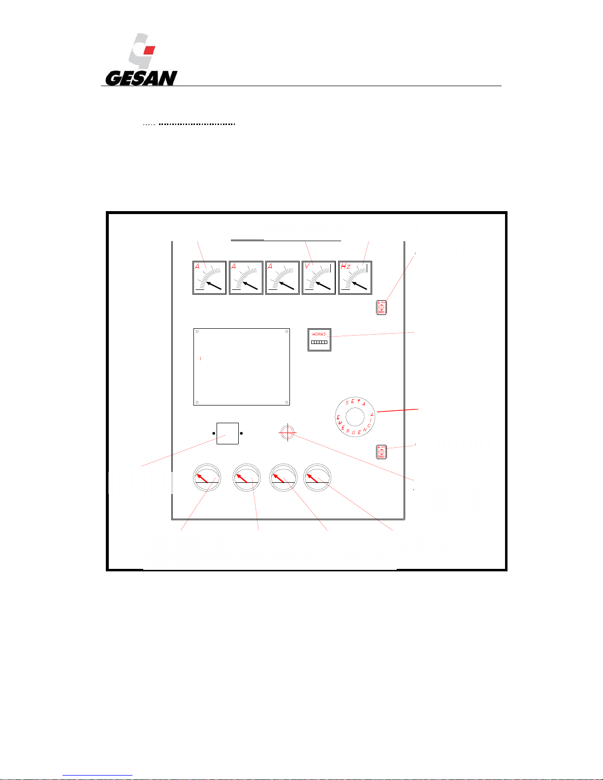
Below you can see a generic control panel, which contains all its electric and mechanical
possibilities.
Picture 5- Generic control panel
AMMETER
(OPTIONAL)
OIL
PRESSURE
(OPTIONAL)
AMMETER
BATTERY CHARGE
(OPTIONAL)
ENGINE
TEMPERATURE
(OPTIONAL)
FUEL
(OPTIONAL)
AUTOMATIC
FUEL FILL
SELECTOR
(OPTIONAL)
LOCK
HOUR METER
(OPTIONAL)
LOCK
FREQUENCY METER
(OPTIONAL)
VOLT METER
(OPTIONAL)
AUTOMATIC
CONTROL UNIT
EMERGENCY
BUTTON
DIFFERENTIAL
(OPTIONAL)
Page 11
RENTAL & SILENT ENERGY RENTAL GENSETS 4.4
10
3.1.1. DEEP SEA digital control plate
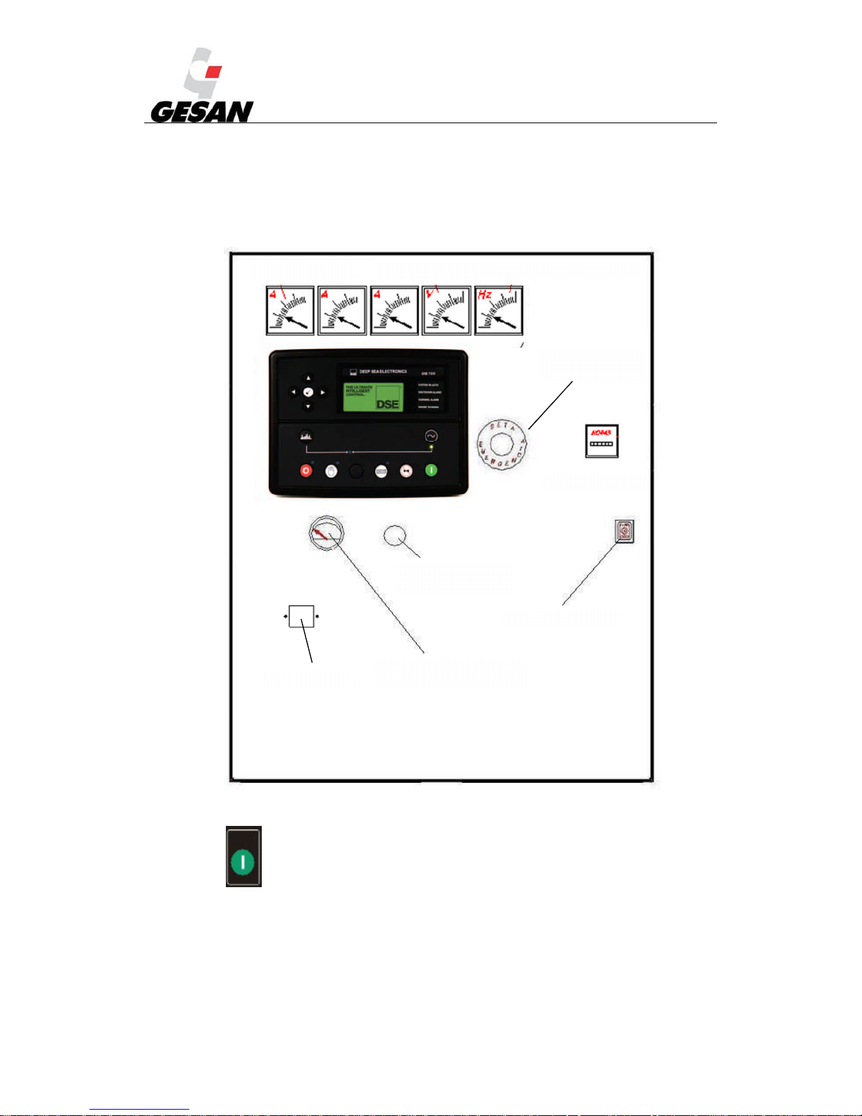
If you have acquired a generator unit with a DEEP SEA 7310 control board, the switchboard will
look like the following diagram:
DIFERENCIAL
Picture 6 - Control panel on Deep Sea control board All the instruments are optional.
Note: The button on the control board fulfils the same function as the diagnosis button (in OFF/AUTO mode).
DIFFERENTIAL
DIAGNOSIS
BUTTON
LOCK
AMMETER
BATTERY CHARGE
AMMETER
FREQUENCY METER
VOLT METER
EMERGENCY
BUTTON
HOUR METER
Page 12
RENTAL & SILENT ENERGY RENTAL GENSETS 4.4
11
3.1.2. INTELIGEN digital control plate
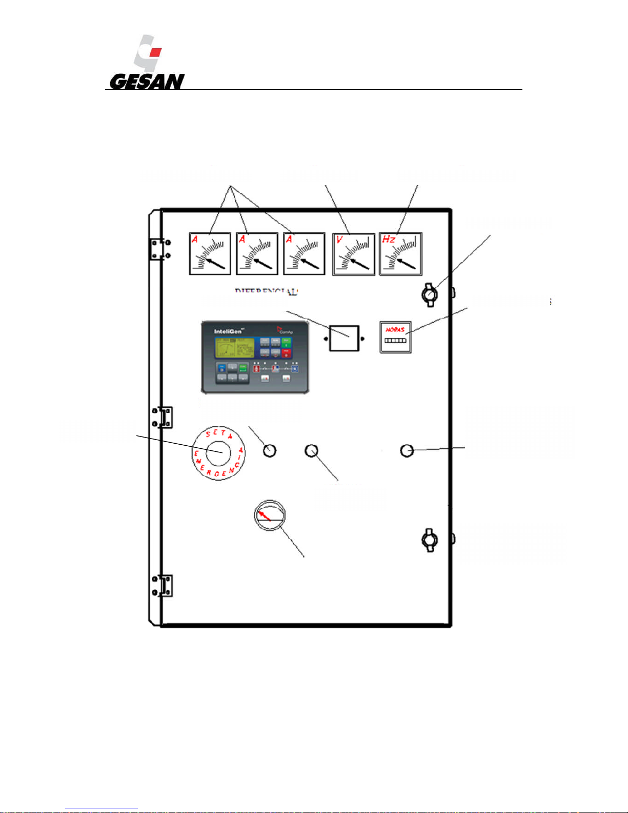
If you have acquired a generator unit with an INTELIGEN control board, the electric panel will look
like the following diagram:
Picture 7 - Control panel on InteliGen
DIFFERENTIAL
AMMETER VOLT METER FREQUENCY METER
LOCK
HOUR METER
GREEN BUTTON
FOR FUEL
GREEN ON
LIGHT
AUTOMATIC FUEL
FILL SELECTOR
(OPTIONAL)
MASTER/SLAVE
SELECTOR
(OPTIONAL)
FUEL GAUGE
EMEGENCY
BUTTON
Page 13
RENTAL & SILENT ENERGY RENTAL GENSETS 4.4
12
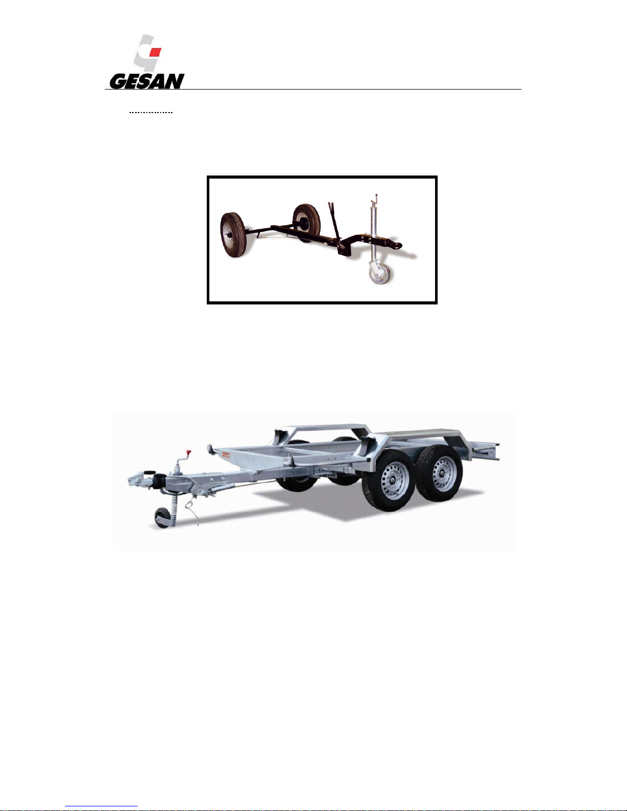
3.2. TRAILER
The generator unit may have a transport trailer.
On-site trailer: its use is limited to areas of private use. It has a DIN type tow hitch, parking
brake and jockey wheel.
Picture 8- On-site trailer
Approved speed trailer: suitable for use on public roads. It incorporates inertia and parking
brakes (only in models heavier than 750 kg), a DIN or ball type tow hitch, identification plate
with the chassis number, jockey wheel, lights kit and mudguards (supplied separately).
Picture 9 Approved speed trailer
Note: The European Community authorises people with driving licences for vehicles
type B, C and D to drive vehicles with a trailer with a maximum authorised weight of 750 kg, or
greater in the case of class B licences when the maximum authorised weight of the trailer does
not exceed the tare of the car towing it and the sum of the authorised maximum weights of both
vehicles does not exceed 3500 kg. Check the Maximum Authorised Weight (MAW) of the
generator set supplied by GRUPOS ELECTRÓGENOS EUROPA S.A. is lower than the
Maximum Towable Weight (MTW) with or without brake depending on the trailer supplied. It is
not necessary to contract a special insurance policy for towed loads weighing less than 750kg,
simply notify the company with which you are insured as towed items are included in the policy.
If it exceeds 750 kg an independent insurance policy must be taken out. Once you have acquired
Page 14

RENTAL & SILENT ENERGY RENTAL GENSETS 4.4
13
the trailer, GRUPOS ELECTRÓGENOS EUROPA S.A will provide the relevant documentation.
If it exceeds 750 kg, the approved trailer must be taken to the Traffic Office to obtain a trailer
licence board (red in Spain).
When selecting the tow hitch take into account the maximum weight the vehicle can tow.
The formalities for driving legally must be carried out by the owner. Once the generator
set has been received, contact GRUPOS ELECTRÓGENOS EUROPA S.A and they will send
you the vehicle roadworthiness inspection card. Then the formalities must be completed to
obtain the vehicle registration and permission to drive on public roads (ITV in Spain, MOT in
the UK).
Page 15
RENTAL & SILENT ENERGY RENTAL GENSETS 4.4
14
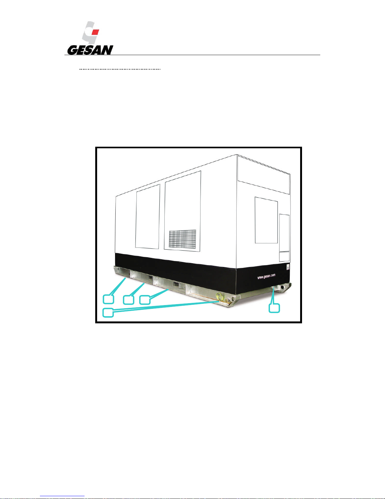
3.3. LIQUID COLLECTION TRAY
The generator set may include a liquid collection tray, to avoid spills coming from the
unit (fuel, oil or coolant), with a capacity of 110% of the total volume of the liquids in the
generator set.
It is the installer's responsibility to take the appropriate measures to avoid possible spills
of pollutants. If your generator set does not include the collection tray and you feel it should,
please contact our technical department.
Picture 10- Liquid collection tray
1) 4 drainage plugs (2 on each side of the tray)
2) Through holes for the fork lift arms
3) Level sensor (optional)
2
2
113
Page 16
RENTAL & SILENT ENERGY RENTAL GENSETS 4.4
15
4. INSTALLATION OF THE GENERATOR SET
This manual describes the installation of a generator set from the RENTAL range
composed of a diesel engine, an alternator and a switchboard. For all particular applications, our
technical services will advise you.
4.1. UNLOADING AND TRANSPORT
The unit must be unloaded and transported by qualified staff taking into account at least
the minimum safety conditions.
The ground must be perfectly able to bear the weight of the unit and the hoist.
Ensure that the battery is disconnected.
Ensure the fuel tank is empty.
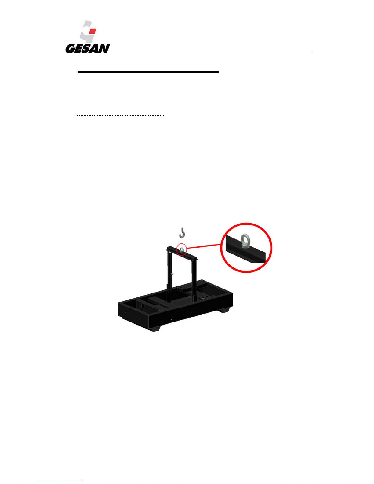
With the fork lift, position the open arms under the chassis so they are equidistant with
respect to the elevation gantry.
With the crane, hoist using the elevation gantry eyebolt.
The picture below shows a diagram of a generator set equipped with a gantry with one
single point of elevation.
Picture 11- Elevation gantry
If your unit has a trailer there are two possibilities:
Page 17

RENTAL & SILENT ENERGY RENTAL GENSETS 4.4
16
Trailer 1 - On-site trailer: It is secured with a DIN type tow hitch and safety chains to the back
of the towing vehicle. This trailer is not authorised for use on public roads. Use the parking
brake when necessary.
Trailer 2 - Trailer with approved speed: Take into account the legal considerations detailed in
point 3.3.
Always exercise the following precautions:
Verify that the tow hitch and the coupling of the towing vehicle to the trailer are of a suitable size
for a load greater than or equal to the gross load of the vehicle to tow.
Verify there is no wear or damage to the tow hitch or coupling, and never tow the unit if there is any
excessive wear or any part is damaged.
Verify that the coupling is correctly secured to the towing vehicle.
Monitor the condition of the trailer's tyres.
Connect the safety hook to the bumper or the back of the towing vehicle, never to the generator set
or the tow hitch itself.
Check that the brakes of both the trailer and the towing vehicle are in perfect condition.
Verify that the indicator and brake lights of the trailer are correctly installed and function correctly.
At the end of each trip, apply a film of grease to the coupling of the towing vehicle and the ring of
the trailer. Before towing again, clean it and grease it again.
Install the safety chains in the units that include the on-site trailer.
Page 18

RENTAL & SILENT ENERGY RENTAL GENSETS 4.4
17
4.2. INSTALLATION OF MOBILE UNITS
Mobile units are those that change workplace at least twice a year. This manual describes the
installation of a “generic” generator set composed of a diesel engine, an alternator and a switchboard. For
all particular applications, our technical services will advise you.
4.2.1. Location
This type of unit must be installed in well-ventilated places, thus ensuring sufficient flow of coolant
air and that the fumes from the combustion do not recirculate towards the engine's air intake.
The unit shall be located in a place fully able to bear the weight of the generator set, guaranteeing
both horizontal and vertical stability.
There must be sufficient distance to allow access to the inside of the generator set (minimum 1
metro distance to any building or wall, with the doors of the generator set fully open).
Avoid installation in damp places or in areas where water may get into unit.
* Note: The exhaust has the option of a spark arrester at the exhaust output.
4.2.2. Fuel
In light of the current laws, you must take special care when storing fuel classified as a hazardous
product. The generator set shall be installed with a tank for daily consumption.
Before starting work, check the amount of fuel in the tank and ensure there is enough.
There is the optional of quick fuel connectors, which are connected using ducts through the
machining of the casing.
You must take into account a number of points:
a. For coupling and decoupling, move the bushing of the female connector back.
b. Make sure the intake circuit from the external tank does not contain air.
c. In the external tank, the intake end must be the male and the return the female of the 3/8
BSP connectors.
d. The return must be correctly connected.
e. Both connectors must be sealed; they close when disconnected.
f. It is important that the distance between the supply tank and the generator set is as short as
possible. In the event of abnormal behaviour (insufficient power if there are intake problems)
reduce the distance or increase the diameter of the hoses. The following table shows the
maximum distances
Page 19

RENTAL & SILENT ENERGY RENTAL GENSETS 4.4
18
PERKINS
Group Engine
Max distance/Tube
diameter
Maximum suction
height (m)
Flow (l/h)
Maximum
pressure (kPa)
DPR 100 1104C-44TAG2 10m / 8-12,7mm 1 150 26
DPR 20 404D-22G 3m / 8mm 0.8 63 30
DPR 250 NC 1306C E87TAG6 3m / 8mm 1 180 30
DPR 30 1103D-33G3 10m / 8-12,7mm 1 150 26
DPR 30 NC 1103A-33G 10m / 8-12,7mm 1 150 26
DPR 45 1103C-33TG3 10m / 8-12,7mm 1 150 26
DPR 45 NC 1103A-33TG1 10m / 8-12,7mm 1 150 26
DPR 500 NC 2506A-E15TAG2 3m / 15mm 3 413 30
DPR 60 1104C-44TG3 10m / 8-12,7mm 1 150 26
DPR 60 NC 1103A-33TG2 10m / 8-12,7mm 1 150 26
DPR 80 1104D-E44TAG2 3m / 8mm 1.5 130 10
DPR 80 NC 1104A-44TG2 10m / 8-12,7mm 1 150 26
VOLVO
Group Engine
Max distance/Tube
diameter
Maximum suction
height (m)
Flow (l/h)
Maximum
pressure (kPa)
DVR 140
NC
TAD 532 GE 6m /12 mm 1.5 360 35
DVR 150 TAD 751 GE 6m /12 mm 1.5 240 35
DVR 200 TAD 753 GE 6m /12 mm 1.5 240 35
DVR 200
NC
TAD 733 GE 6m /12 mm 1.5 360 35
DVR 250
NC
TAD 734 GE 6m /12 mm 1.5 164 35
DVR 315
NC
TAD 941 GE 6m /12 mm 1.5 108 20
DVR 400
NC
TAD 1344 GE 6m /12 mm 1.5 120 30
DVR 460
NC
TAD 1345 GE 6m /12 mm 1.5 125 30
DVR 500
NC
TAD 1641 GE 6m /12 mm 1.5 170 20
Page 20
RENTAL & SILENT ENERGY RENTAL GENSETS 4.4
19
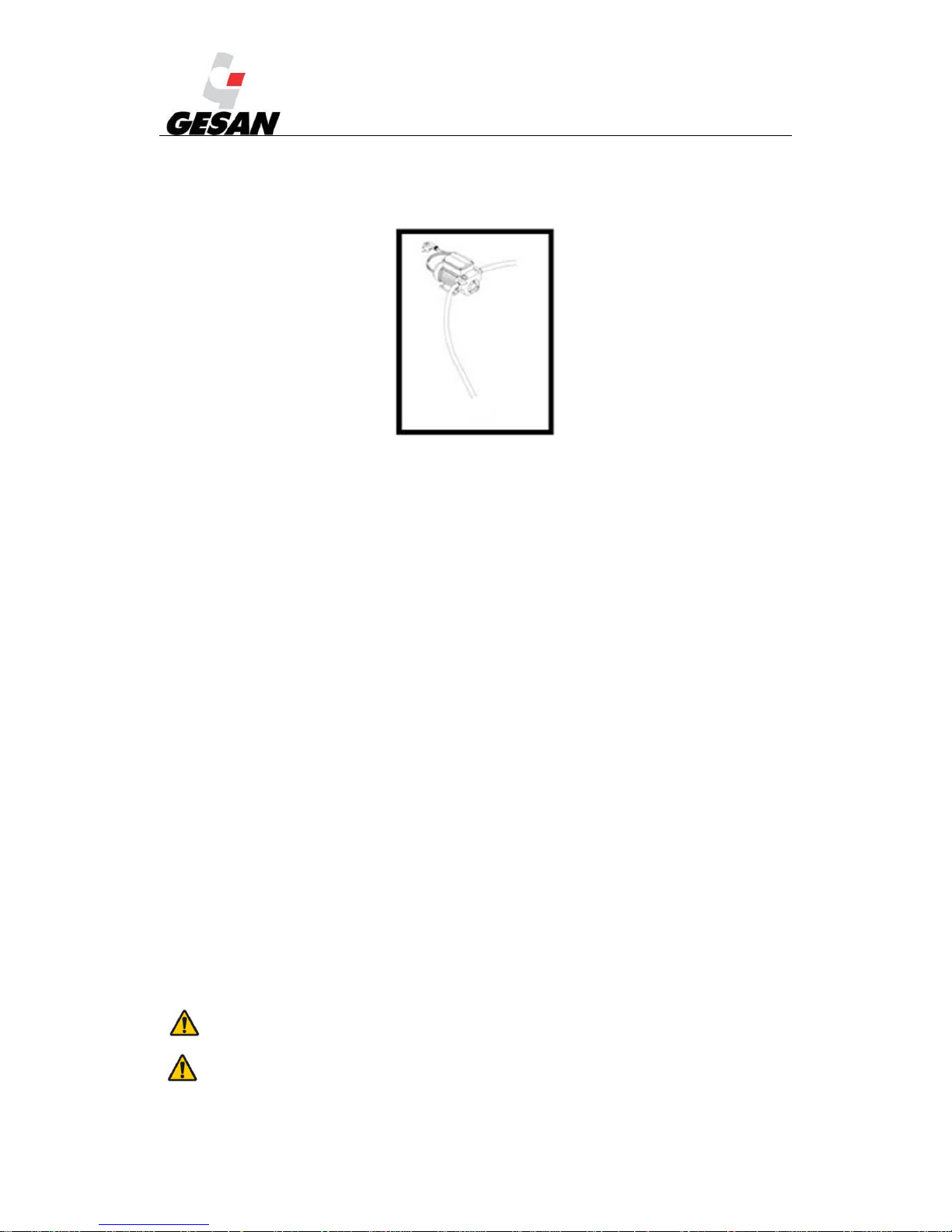
The unit may have an automatic suction transfer pump (SAB-BE), with eccentric self-adjusting
blades. Inside there is a 352-micron removable filter that must be used.
Picture 12- Pump SAB-BE
Note: If the distance from the unit is going to be greater than that recommended, the pump must be removed and
located near the external tank. The pump will work if the unit is running and has an OFF/AUTO switch on the door of the
switchboard integrated in the unit.
4.2.3. Exhaust
When installing the exhaust you must take into account the load losses caused and its insulation.
The suspension of the elements that comprise it, the level of noise produced and the polluting
emissions produced.
The compensators and flexible tubes of the installation absorb the movements (due to the
dilatation and vibrations).
4.2.4. Starting the generator set
The starting system for the generator set is electric. It consists of a 12 or 24 V electric engine
powered by one or several lead-acid batteries.
Low temperatures make it more difficult to start the engine. A start failure (three tries without
success) shall lead to the order to stop the whole generator set. For these temperature conditions, and to
avoid this and ensure the generator set starts correctly at any external temperature, you have the option of
installing a boiler (heating of the cooling water) by means of a preheating system connected to the grid.
This system functions automatically, governed by a thermostat (factory-regulated to between 40 and
60ºC), and indicated in the panel with a reading on the DEEP SEA 4420 module.
If the unit has been sent outside of Spain the dry charged batteries shall be commissioned by
removing the plugs and filling each element of the battery with sulphuric acid with a density of 1.28 (or
1.23 in tropical countries). Leave it to settle for at least 20 minutes and check the level of electrolyte (25
mm above the plates). Never fill it up to the top. Replace the plugs.
It is recommended to wear protective goggles and gloves when filling up the battery acid. Ensure you have access to
running water in the area to clean any affected areas.
You must take safety measures and precautions when performing the tasks indicated in this manual. Special attention must
be paid to short-circuit hazards that may occur when metal objects come in contact with the equipment power terminals.
Page 21

RENTAL & SILENT ENERGY RENTAL GENSETS 4.3
20
If you have acquired an MTU engine, on occasions, with the generator set on and the engine
stopped, the engine's central unit will consume a large quantity of the battery's energy, so it is possible
that it runs flat and it is impossible to start it up again. For this reason, there is a selector on the
switchboard that disconnects the battery in the event of an extended stop. For this purpose, we advise you
to carry out the following start-up process:
1) Switch the selector to position 1.
2) Start up the generator set.
3) Switch the selector to position 0.
Note: Step 1 is strongly recommended, as if the selector is in position 0 once the generator set is running, the board will remain
without a power supply.
IT is recommended to avoid keeping the central unit in position 1 for more than 2 days, as the batteries will discharge
completely, which would impede the generator set starting up again later. If the selector is moved to 0 while the generator
set is running, the generator set will not stop. The battery can only be disconnected with the engine stopped.
Page 22

RENTAL & SILENT ENERGY RENTAL GENSETS 4.3
21
If your generator set does not have an MTU engine installed, you will find an informative sticker
warning you to disconnect the battery to avoid it discharging during extended stops.
4.2.5. Electrical connection
The cables that supply the consumers must be connected by qualified staff, to the outputs U, V, W
and N or L1, L2, L3 and N or in the electrical outlets. The aforementioned qualified staff must follow
these safety instructions:
1) Use the relevant personal protection equipment to carry out the electrical installation
safely.
2) Place the control module selector in the STOP position.
3) Ensure the emergency stop button has been pressed.
4) Verify that the battery is disconnected.
5) Disconnect the supply from the electrical grid.
6) Before starting to install the equipment that has been supplied, ensure it can provide the
voltage and frequency you need.
7) Handle the cables with maximum care as they may be live.
8) You must connect the generator set to earth correctly (labelled on the unit with the
following icon ).
The four-polar switches have strips at the output to facilitate connection of the conductors and
avoid their deterioration caused by the repetition of the connection.
The outlets may or may not, depending on the option selected, have individual protection per
outlet, thus differentiating the protection per outlet from the general unit using an individual switch.
Page 23
RENTAL & SILENT ENERGY RENTAL GENSETS 4.3
22
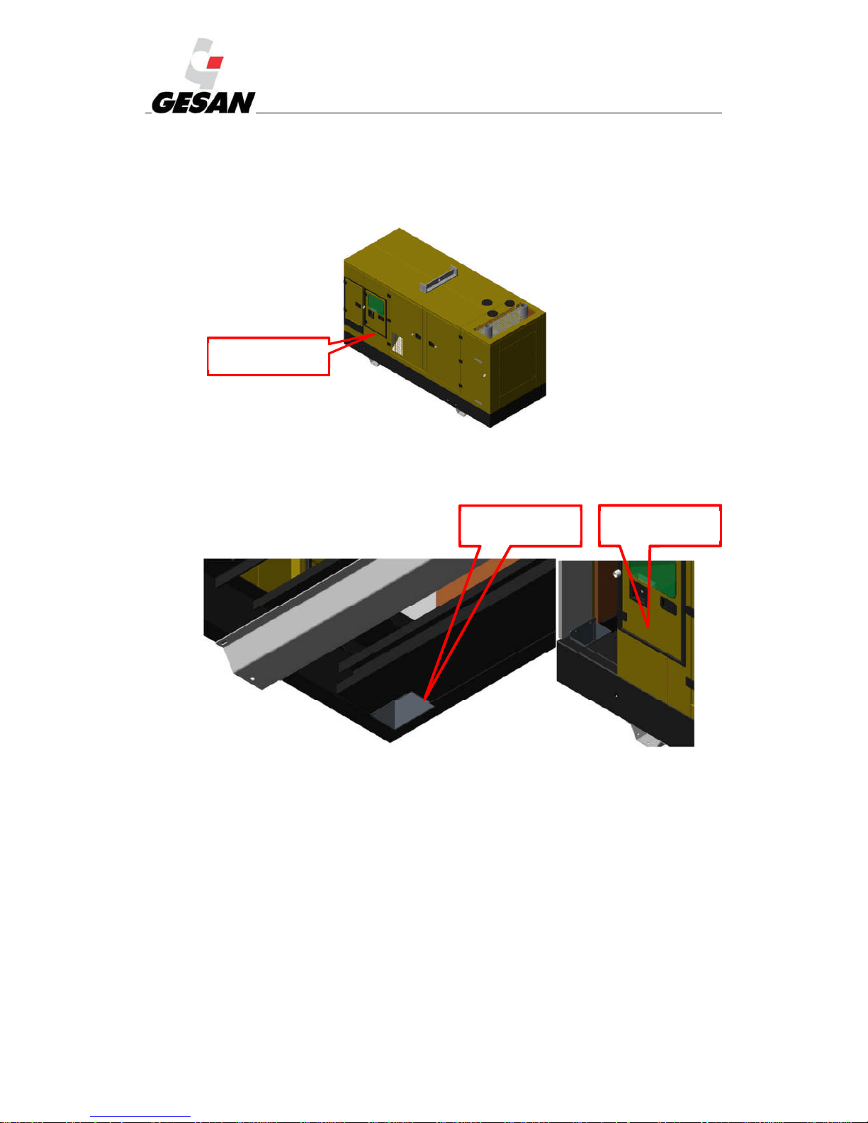
In isolated power box gensets, mains cable instalation could be realized by two ways:
-Lateral power cables outlet: This way, power cables come out by the trapdoor with protective
rubber placed in the control box door, as shown in the Picture:
Picture 13- Lateral power cables trapdoor entry
-Power cables lower exit: This way, the power cables enter directly from the bedplate lower part
throught the duct adapted in the base.
Picture 14- Power cables entry by bedplate
In the installation drawing you could find the exact measures, and also relative positions.
Lateral power cables
inlet.
Power cables lower
entry
Power cables lower
exit
Page 24

RENTAL & SILENT ENERGY RENTAL GENSETS 4.3
23
If the unit has been sent outside of Spain the dry charged batteries shall be commissioned by
removing the plugs and filling each element of the battery with sulphuric acid with a density of 1.28 (or
1.23 in tropical countries). Leave it to settle for at least 20 minutes and check the level of the electrolyte
(25 mm over the plates); never fill it up to the top. Replace the plugs.
4.3. STORAGE
If you believe your generator set will be inactive for some time, you must follow the instructions
below:
1) Position the control board in STOP.
2) Press the emergency button to avoid unwanted start-ups when it is connected in future.
3) Empty the fuel tank. Ensure the interior protection valve is in the correct position.
4) Leave the battery disconnected, using the battery disconnector.
5) Do not leave the unit in a place where dust accumulates or in excessively damp places.
6) Do not use pressurised water when cleaning the unit.
7) In order to better preserve the engine, refer to its manual; this manual has been supplied along
with this document.
8) In order to better preserve the alternator, refer to its manual; this manual has been supplied along
with this document.
Page 25

RENTAL & SILENT ENERGY RENTAL GENSETS 4.3
24
5. COMMISSIONING AND STOPPING
Once the installation of the generator set has been completed, or its location has been changed,
follow these steps:
1) Check the unit is correctly balanced and supported on the ground.
2) Check and, if necessary, retighten the screws that secure the engine-alternator assembly to the
bedplate.
3) Check and, if necessary, retighten the screws securing the radiator to the bedplate and engine.
4) Check and, if necessary, adjust the fan and battery charge alternator belts, and their alignment. If
the power of the generator set exceeds 750 kVA, this recommendation is compulsory. Contact
your distributor to request specific information to carry out this task.
5) Check the bodywork is sealed, especially the upper casing. Clean and reseal if necessary.
6) Check the connections of the battery terminals, and retighten, clean and grease when necessary.
Before commissioning the generator set, follow these steps:
1) Check the levels: verify the levels of the oil, coolant and fuel in the control module. Close
the battery disconnector.
2) Release the emergency button, if it has been pressed.
3) Supply the mains circuit and verify that the voltage indicator gives a suitable reading.
4) Verify the circuit breaker (the lever must be up).
5) Once the tasks prior to commissioning are finished, ensure the control module selector of the
generator set is in the desired position. For this, duly read how your control module works in point 6
(OPERATION MANUAL).
To stop the unit:
1) Disconnect the loads.
2) Disconnect the circuit breaker.
3) Leave the engine running at no load for 2 minutes to cool the generator set.
Stop the engine by moving the selector on the control board to the OFF position.
5.1. GENERATOR SETS AND POWER FACTOR CORRECTORS
The power factor (cos φ) of the loads the generator set supplies must be determined. Inductive
power factors below 0.8 can overload the unit. The power factor values for which the generator set has
been designed are between 0.8 and 1 (inductive).
Special attention must be paid to installations that have power factor correction units (capacitor
banks) to avoid capacitive power factors. These can lead to instability in the voltage and dangerous
overvoltages.
Page 26

RENTAL & SILENT ENERGY RENTAL GENSETS 4.3
25
5.2. OPERATION AT LOW LOAD IN DIESEL ENGINES
If a diesel engine works at a load system below 25-30% of its nominal power, certain symptoms will
be observed that must be taken into account. The engine is designed to work at maximum power and,
consequently, its components (pistons, cylinders and valves) are also designed for this.
When engines work at low load, the energy supplied by the cylinders is lower, and consequently the
pressure and temperature within the cylinders are also lower. Therefore, the dilatation of the material and
the seal of the valves are not suitable, and oil will leak into the cylinders, burning along with the fuel,
which increases the engine's oil consumption.
Oil also appears in the intake commutator.
Turbocharging systems are used to increase the power of an engine by increasing the amount of air
that enters the cylinders. When the system operates the air is sucked in, causing vacuums of up to500 mm
H2O, with pressure ratios of 3:1. The gaskets of the system are designed to work at the point of maximum
efficiency. If the engine works at low load, the system works more slowly (less energy in the exhaust gas,
as less fuel is burned) and the air is less compressed allowing oil to appear, which reaches the conmutator
impregnating its walls and, oil leaks occasionally form.
Due to this running at low load, the combustion worsens (there is an excess of fuel in the cylinders)
causing a characteristic blackening of the exhaust gas.
In addition, more cinder is formed in the valves, in the piston crown and exhaust system. Therefore,
the time intervals of 2500 hours between exhaustive maintenance sessions must be reduced. There will
also be a dilution of the fuel in the lubricant oil.
The following precautions are recommended:
Running at low load must be avoided or limited. If you start the generator up weekly at no load, this
should be for 15 minutes or less if the batteries are already recharged.
Every year the generator must be subject to full load to eliminate accumulations of cinders in the
engine and exhaust. It may need additional external loads. The load should be increased gradually
over the four hours of operation.
If you anticipate long periods of operation at low load, an additional load using resistor banks will be
necessary.
Page 27
RENTAL & SILENT ENERGY RENTAL GENSETS 4.3
26
6. OPERATION MANUAL
The generator set you have acquired was designed for manual service; it is started up and stopped
manually.
Different elements are described below, depending on the choice of generator set.
6.1. SWITCHBOARD COMPONENTS
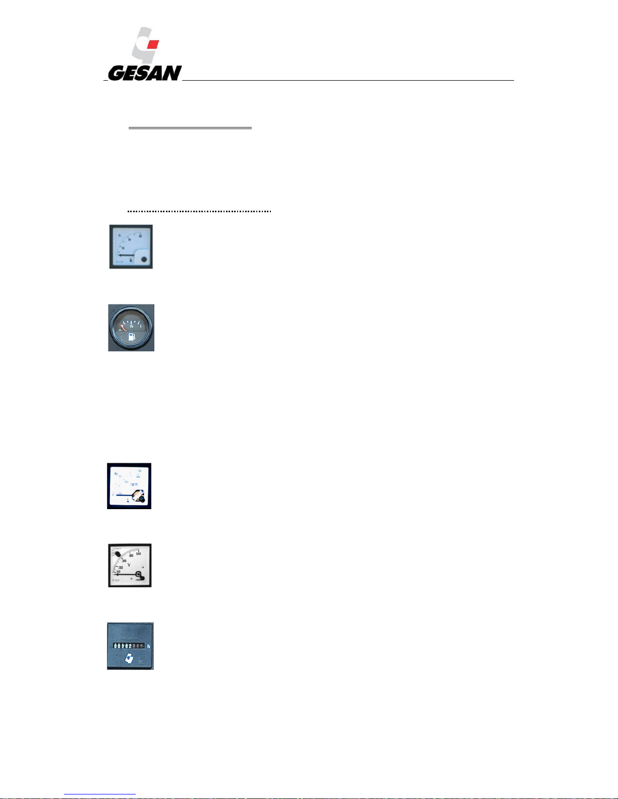
Ammeter:
Ammeter (A), by means of a selector of the different lines of the Generator set.
Indicator dials for parameters of the engine: (Optional)
Oil pressure
Battery charge current
Engine temperature
Fuel level
Frequency meter:
Indicator of generator set frequency (Hz)
Voltmeter with switch.
Voltage meter (V), by means of a selector of the different lines of the generator set.
Hour meter:
Indicator of the hours that the generator set has been operating.
The two digits on the right in red indicate hundredths of an hour. The hours will be indicated from
Page 28
RENTAL & SILENT ENERGY RENTAL GENSETS 4.3
27
the third digit on and they will be displayed in white.
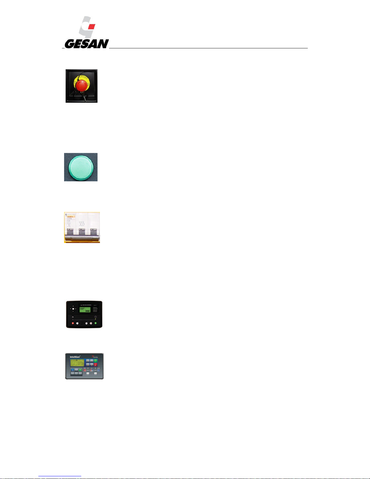
Emergency button:
Pressing it causes the generator set to stop immediately. To cancel it, turn it anticlockwise, but be
sure the emergency is over.
For soundproofed units the emergency button is installed outside of the switchboard (integrated in
the bodywork).
Diagnosis button:
Enables consultation of the engine's parameters when the generator set is stopped (electronically
managed engines). The different generator alarms can also be read here.
Differential:
This is a protection against earth faults of one of the lines, tripping the main protection switch of
the electrical generator.
It is configured to trip when it exceeds 30 mA for residential use or 300 mA for industrial use,
with a delay of 0 s. It is the responsibility of the installer to adjust and seal the differential according to
the current regulations.
DEEP SEA 7310 module;
Automatic module that monitors the mains supply.
ComAp INTELIGEN module (optional)
Module for manual or signaled start-up.
Page 29
RENTAL & SILENT ENERGY RENTAL GENSETS 4.3
28
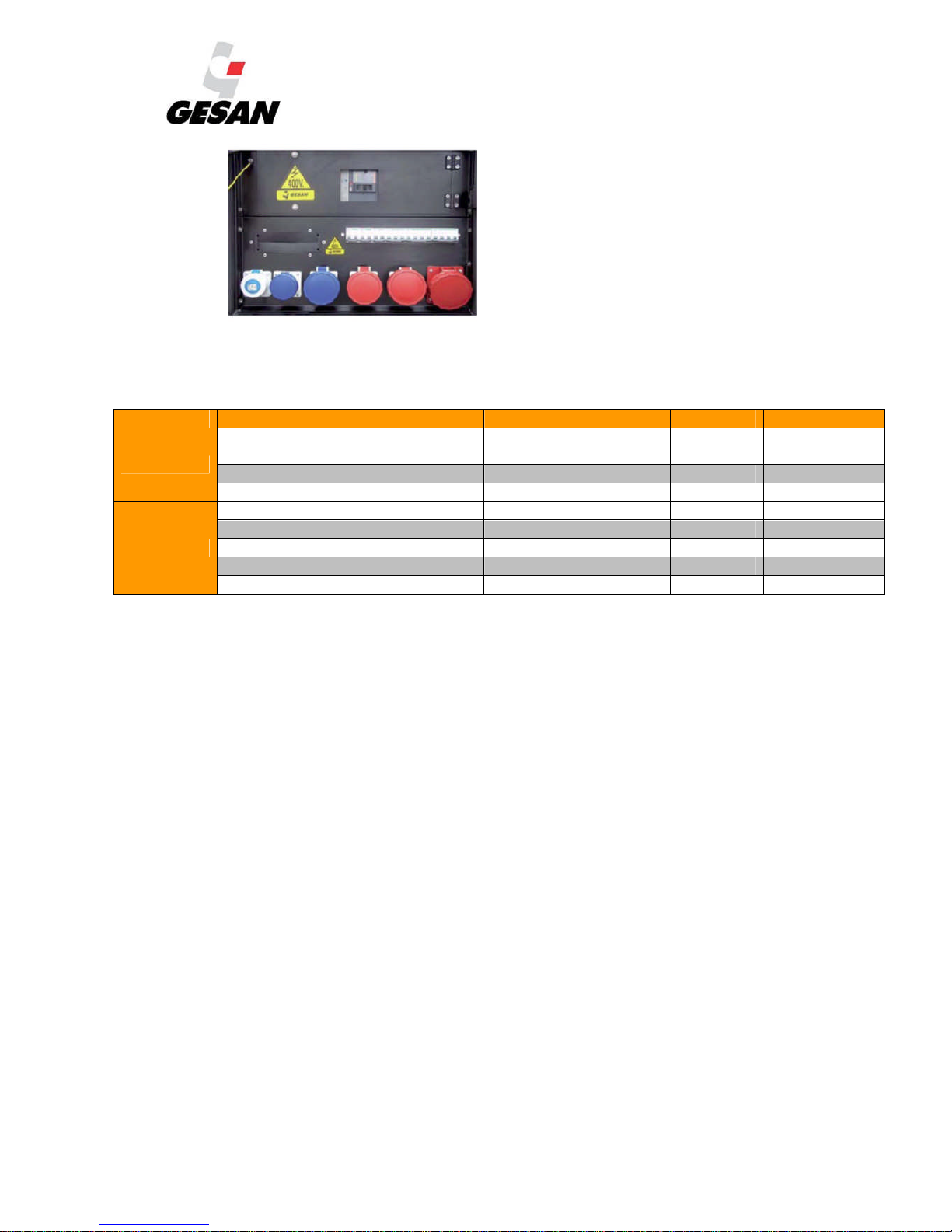
Auxiliary socket panel (standard).
The following table shows the types of sockets included in the power panel for the RENTAL
Series, depending on the power of the generator set supplied by GRUPOS ELECTRÓGENOS EUROPA
S.A
Sockets Type 9-10 kVA 13-25 kVA 30 kVA 40-160 kVA 180-500 kVA
Single phase
1X 16 A. SCHUKO
2F+T *
1 1 1 1 1
1X 16 A. CEE 2F+T 1 1 1 1 1
1X 32 A CEE 2F+T - - 1 1 1
Three phase
1X 16 A CEE 3F+T 1 - - - -
1X 16 A CEE 3F+N+T 1 1 1 - -
1X 32 A CEE 3F+T - - 1 1 1
1X 32 A CEE 3P+N+T - 1 1 1 1
1X 63 A CEE 3P+N+T - - - 1 1
Page 30
RENTAL & SILENT ENERGY RENTAL GENSETS 4.3
29
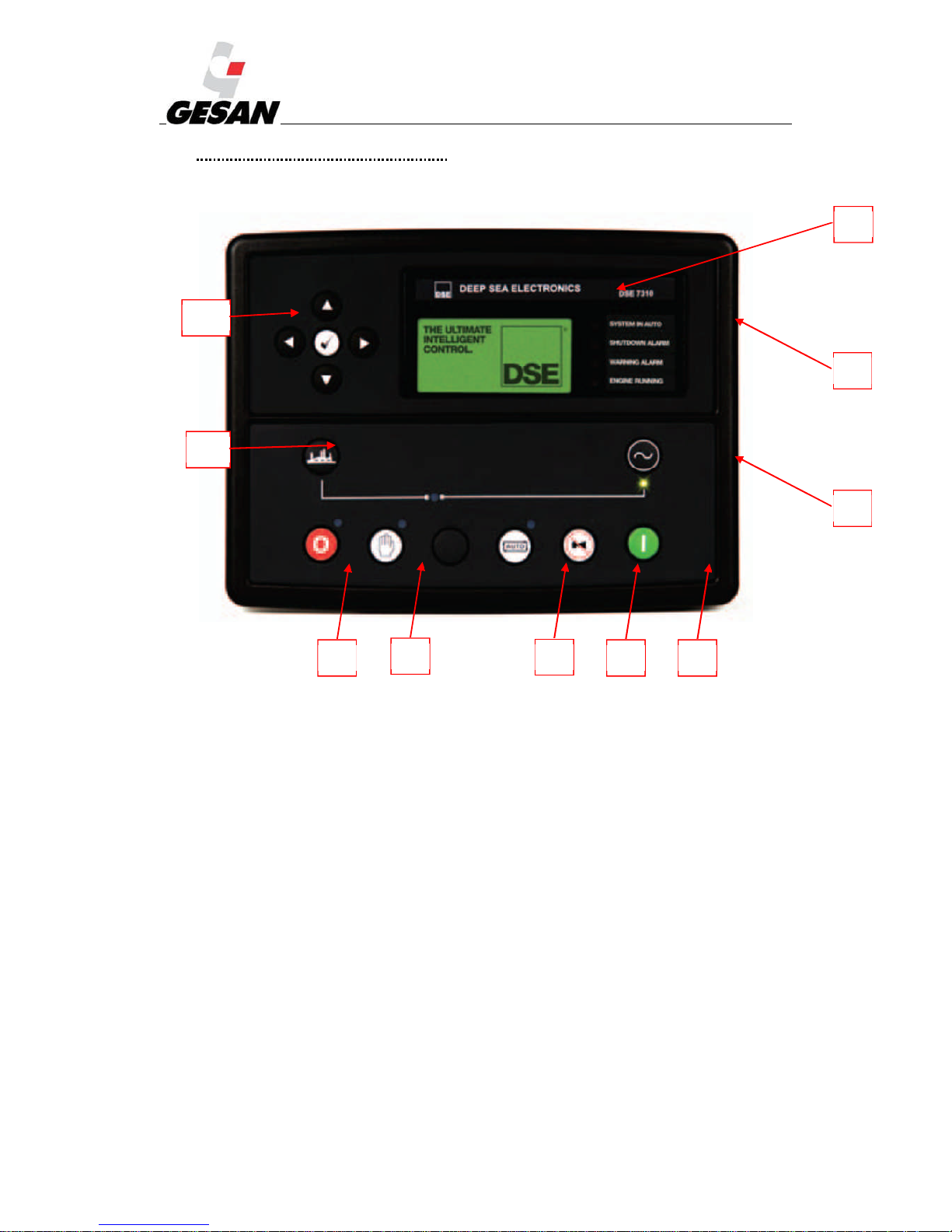
6.2. DEEP SEA 7310 CONTROL MODULE
Picture 15- Deep Sea 7310 control module
1
2
4
5 6
7
8
9
10
11
Page 31
RENTAL & SILENT ENERGY RENTAL GENSETS 4.3
30
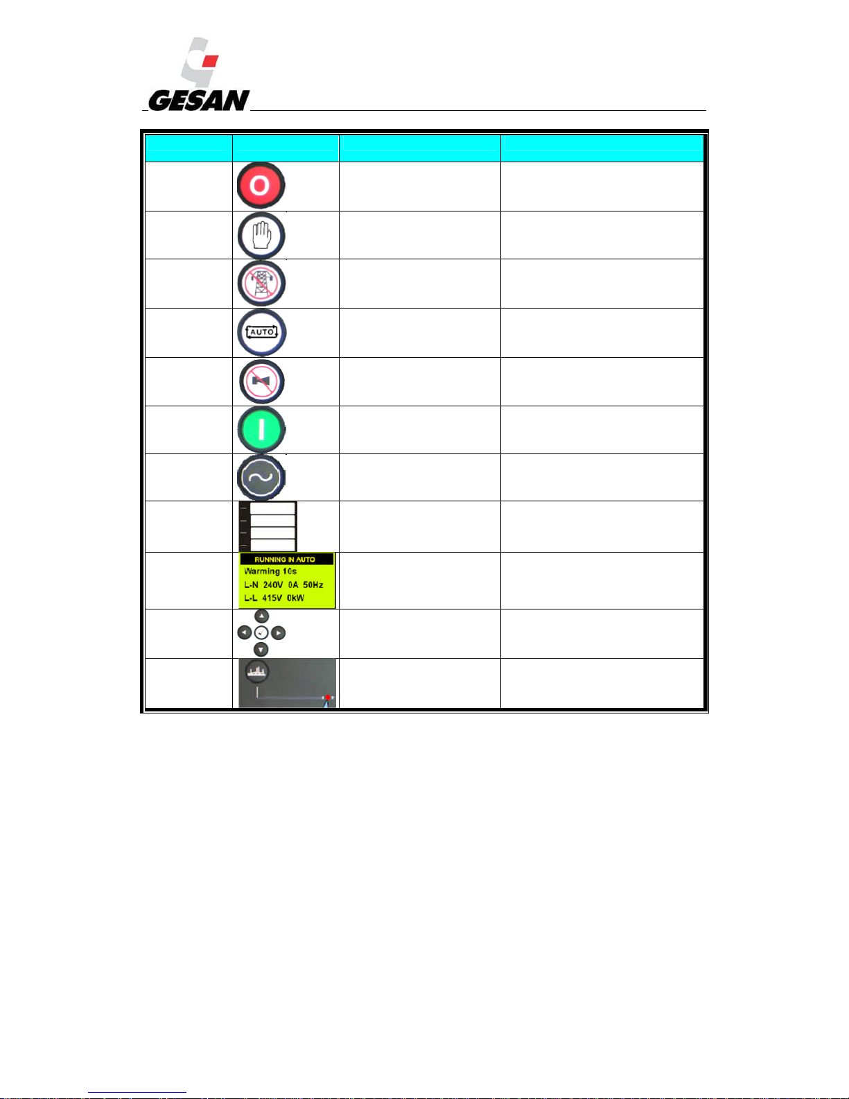
NUMBER SYMBOL DESCRIPTION IDENTIFICATION
(1) Stop button. Red LED
(2) MANUAL mode button Red LED
(3) TEST mode button
Green LED (available on model 7320
only)
(4) AUTOMATIC mode button Red LED
(5)
Mute alarm / Lamp test
button
(6) Generator set start up button
(7)
“Transfer to generator”
button
Green LED on when generator set is
available
(8)
Configurable LED
indicators.
Red LED
(9) Status generator set display.
(10) Menu navigator
(11) “Open generator” button
LED on: generator set is supplying
loads.
Deep Sea 7320 is an automatic control module that monitors the main power supply; if a mains
failure occurs, generator set will start up and loads are transferred. This control module also allows the
option of manual startup. The user can also control all of the generator unit’s parameters as well as the
status of mains power supply. This model is supplied with standby generator sets with or without ATS.
Deep Sea 7310 control module is supplied with “standby by signal” type units.
Page 32
RENTAL & SILENT ENERGY RENTAL GENSETS 4.3
31
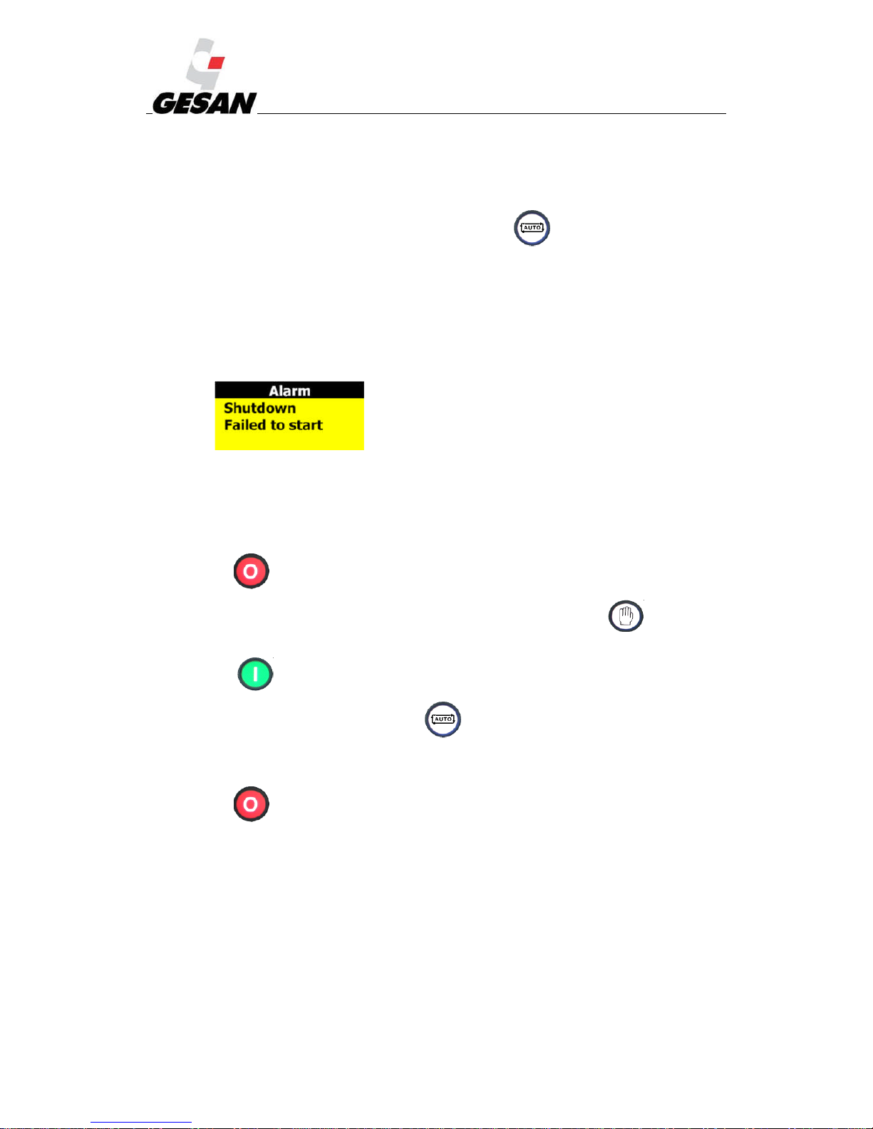
AUTOMATIC mode (AUTO):
This is the normal operating mode.
The automatic mode is activated by pressing the button (4), at which point the LED at
the top of the button will turn on, indicating that it is operational.
(7320) If the mains power supply fails for longer than the unit’s programmed period, the LED
(7310) If a mains failure occurs, the external management system should send a startup signal
to the generator set, at which point the LED indicating remote startup active (8) turns on and the
startup process of the generator set begins.
The engine will start; if it should fail, there will be a maximum number of startup attempts (3).
If all three startup attempts have been unsuccessful, the information screen will display a startup
alarm:
When mains power is restored (or when the remote startup signal disappears) there will be a
period of time in which the engine will continue operating at no load to cool down before stopping
completely.
If a mains failure occurs or remote startup signal appears again during the no-load operating
period (cool-down period), the generator set would begin the startup process again.
Press (1) or the emergency stop button to intentionally stop the unit.
MANUAL mode: The manual mode is activated by pressing the button (2), at which
point the LED at the top of the button will turn on, indicating that it is operational.
Press (6) to start up the unit.
To terminate this mode, press the button (4).
Once button (4) is pressed and there is adequate mains power supply (without the remote
startup signal activated), the shutdown sequence will begin as described in the automatic mode.
Press (1) or the emergency stop button to intentionally stop the unit.
Page 33
RENTAL & SILENT ENERGY RENTAL GENSETS 4.3
32
ALARMS:
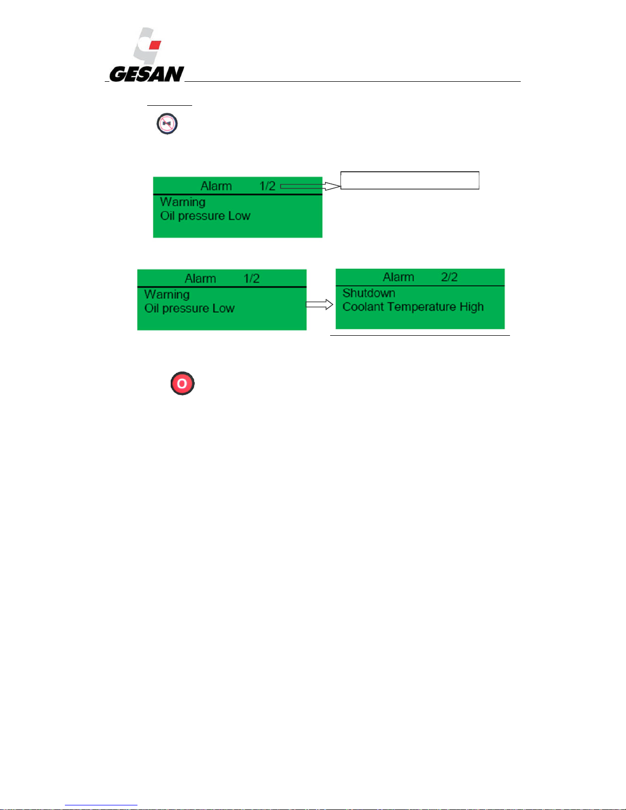
Press (5) to silence the audible alarm and acknowledge the common alarm LED.
By default, the information screen will show the status screen and if an alarm occurs, the
screen will display the following:
If shutdown occurs while a warning is active, the screen will cycle through the active alarms:
The warnings do not entail generator unit shutdown.
Press (1) to reset all the alarms which causes the stops. If the cause which caused the
alarm has not gone we cannot reset the board
Alarm 1 of a total of 2 present alarms
Page 34
RENTAL & SILENT ENERGY RENTAL GENSETS 4.3
33
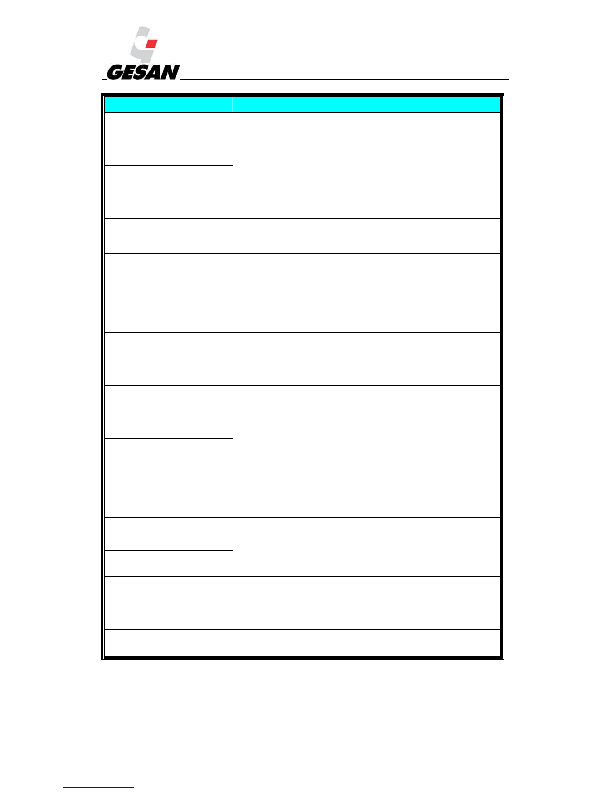
INCIDENT ALARM DESCRIPTIONS
ALARM
Warning
Charge failure
Charge alternator voltage not detected
ALARM
Warning
Battery under voltage
Battery voltage beyond established limits
ALARM
Warning
Battery over voltage
ALARM
Warning
Fail to Stop
After shutdown command, engine continues running.
Could also indicate faulty oil pressure sender
ALARM
Warning
Auxiliary inputs
Auxiliary inputs can be configured and will display the message as
written by the user
ALARM
Warning
Low fuel level
Fuel level below established limits
ALARM
Warning
CAN ECU error
Engine ECU has detected a warning alarm. The exact error is also
indicated on module display (only for electronic engines).
ALARM
Warning
kW overload
The total kW are above the warning setting.
ALARM
Warning
Earth fault
The earth fault current is above alarm settings (only under customer
request)
ALARM
Warning
Negative phase sequence
Indicates “out of balance” current loading of the generator set.
ALARM
Warning
Low oil Pressure
Low oil pressure, below established limit
ALARM
Warning
Engine high temperature
Engine temperature beyond established limits
ALARM
Warning
Engine low temperature
ALARM
Warning
Underspeed
Engine speed beyond established limits
ALARM
Warning
Overspeed
ALARM
Warning
Generator over frequency
Generator set frequency beyond established limits
ALARM
Warning
Generator under frequency
ALARM
Warning
Generator over voltage
Generator set voltage beyond established limit
ALARM
Warning
Generator under voltage
ALARM
Warning
High Current
Current of the generator set output beyond established limits
Page 35
RENTAL & SILENT ENERGY RENTAL GENSETS 4.3
34
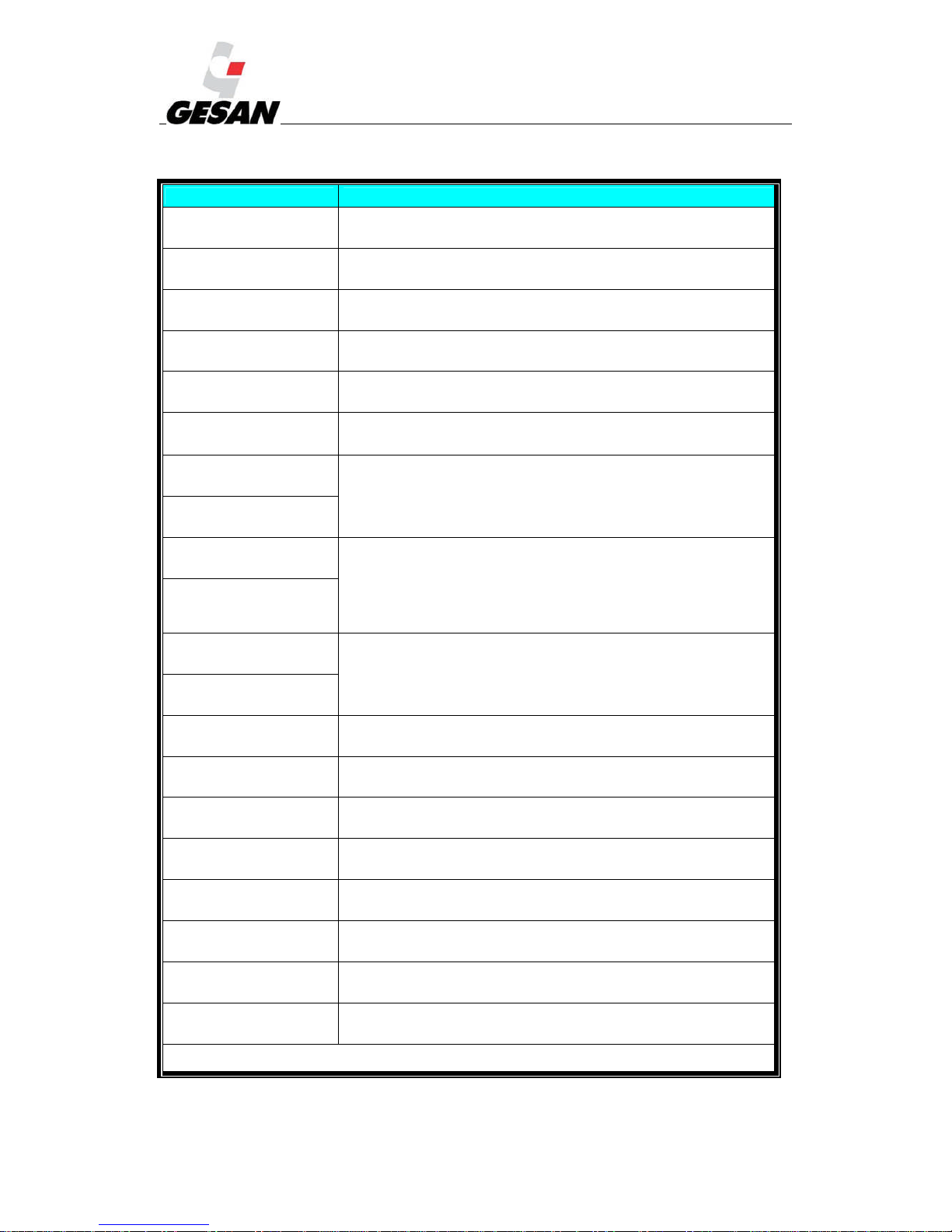
INCIDENT DESCRIPTION OF SHUTDOWNS
ALARM
Shutdown
Earth fault
The earth fault current is above shutdown settings (only under customer
request)
ALARM
Shutdown
Failed to Start
Engine does not start, three attempts made.
ALARM
Shutdown
Emergency stop
Controlled shutdown of the unit. It will not be functional until the
emergency stop button has been reset.
ALARM
Shutdown
Low oil pressure
Oil pressure below established limit
ALARM
Shutdown
High temperature
Engine temperature above established limit
ALARM
Shutdown
Phase rotation
The phase rotation is different to the configured direction
ALARM
Shutdown
Overspeed
Engine speed beyond established limits
ALARM
Shutdown
Underspeed
ALARM
Shutdown
Generator over frequency
Generator set frequency beyond established limits
ALARM
Shutdown
Generatp
or under frequency
ALARM
Shutdown
Generator over voltage
Generator set voltage beyond established limit
ALARM
Shutdown
Generator under voltage
ALARM
Shutdown
Oil pressure sender open circuit
Faulty oil pressure sender
ALARM
Shutdown
Auxiliary input
An active auxiliary input configured as a shutdown will cause the engine
to shutdown. The display shows the text as configured by the user.
ALARM
Shutdown
Loss o speed signal
The speed signal from magnetic pick up as not received by the module.
ALARM
Shutdown
ECU data fail
The module configured for CAN operation and doesn´t detect data on
data link.
ALARM
Shutdown
ECU shutdown
Engine ECU has detected a shutdown alarm. The exact error is also
indicated on module display (only for electronic engines).
ALARM
Shutdown
kW overload
The total kW is above the shutdown setting.
ALARM
Shutdown
Negative phase sequence
Indicates “out of balance” current loading of the generator set.
ALARM
Shutdown
High Current trip
Current of the generator set output beyond established limits
Note: If the established limit for
shutdown is exceeded, a corresponding alarm screen will be displayed and on the configurable
LED indicator (8) the Common Shutdown alarm will appear.
Page 36
RENTAL & SILENT ENERGY RENTAL GENSETS 4.3
35
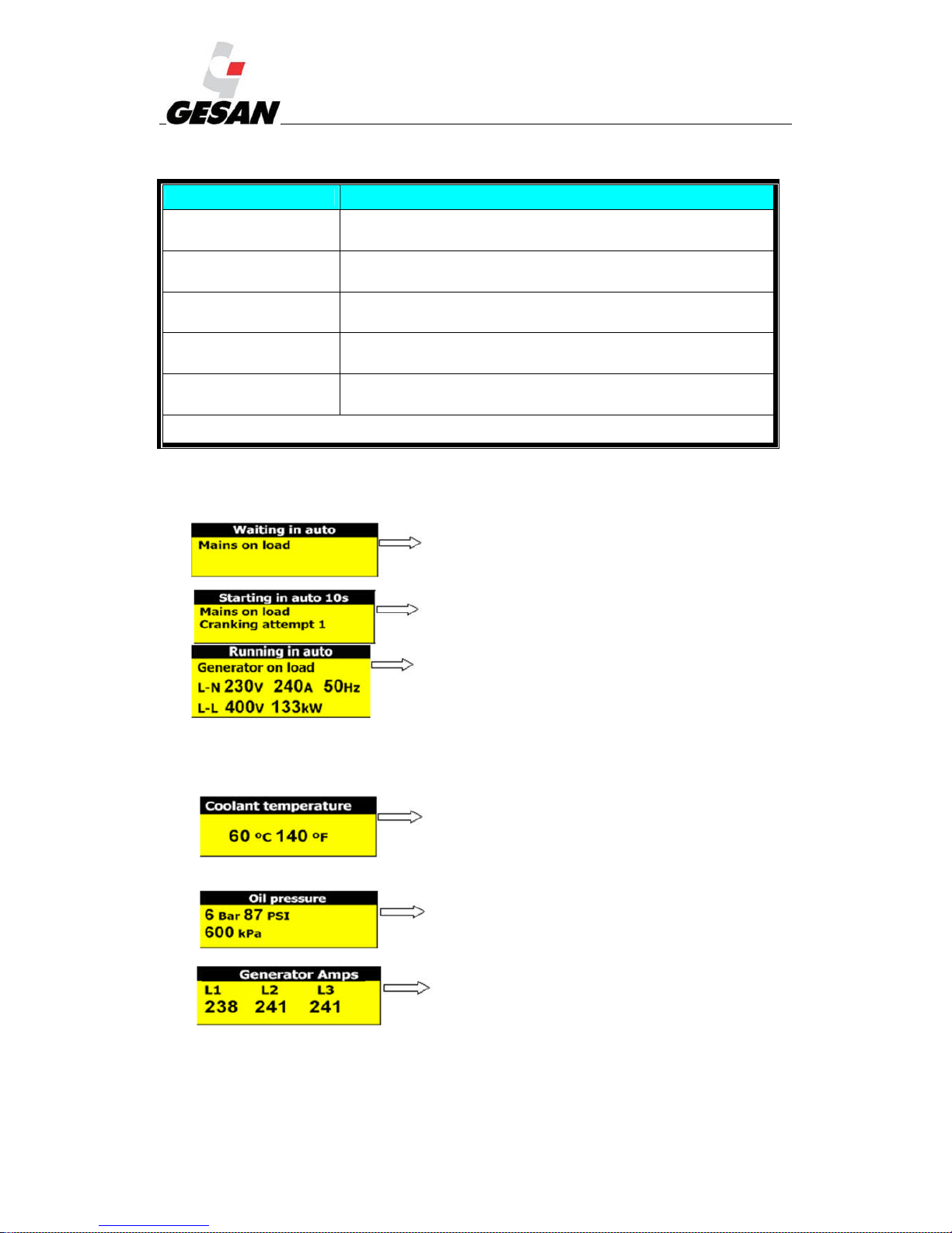
INCIDENT DESCRIPTION OF ELECTRICAL TRIPS
ALARM
Electrical trip
Generator over current
Generator set current above electrical trip setting.
ALARM
Electrical trip
Auxiliary inputs
Auxiliary inputs can be configured and will display the message as
written by the user
ALARM
Electrical trip
kW overload
The total kW is above electrical trip setting.
ALARM
Electrical trip
Earth fault
The earth fault current is above electrical trip settings (only under
customer request)
ALARM
Electrical trip
Negative phase sequence
Indicates “out of balance” current loading of the generator set.
Note: Electrical trips are latching and stop the generator set but in a controlled manner. Firstly de-energize the “close
generator” output to remove the load from the generator set, and later, cool down and shutdown the unit.
Typical LCD Display Screens
Indicates that the generator set will respond to either a
mains failure or an active remote start.
Indicates that generator set is in automatic mode and has
been initiated after a mains failure has been detected.
Indicates generator set running normally in automatic
mode. Also indicates the average line to neutral voltage (LN), the highest of the three phase currents, the rated
frequency, average line-to-line voltage (L-L) and total kilowatts.
Measurement Parameter Display Screens:
Coolant temperature in degrees (ºC) Celsius and
degrees Fahrenheit (ºF)
Displays engine oil pressure in Bar, PSI and kPa.
All three generator line currents.
Page 37
RENTAL & SILENT ENERGY RENTAL GENSETS 4.3
36
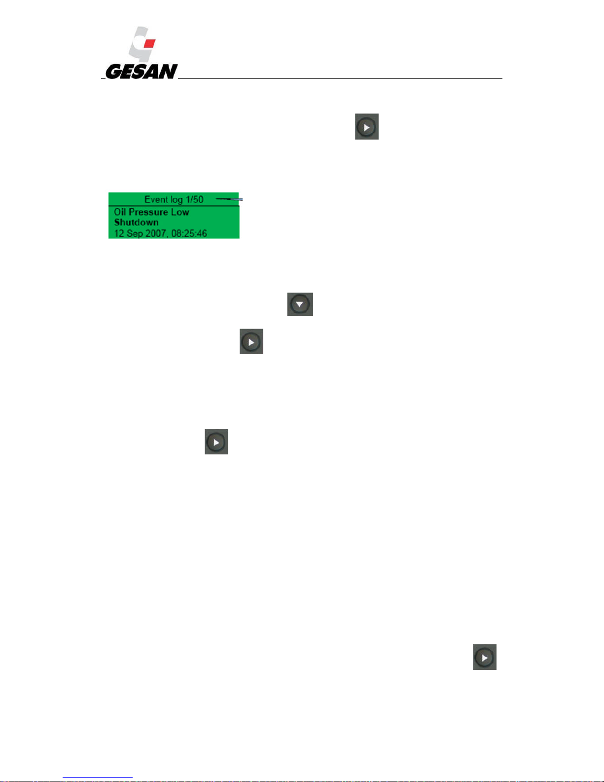
Event Log:
To view the event log, press the following button repeatedly until the LCD display the event
log.
It registers the shutdown alarms occurring in the generator unit. A screen similar to this is shown:
“On September 12, 2007, at 08:25:46, the unit detected that the oil pressure was below the minimum
level and has shut down the generator. It´s the event 1 of a total of 50 logged events”
To move from one event to the next, press .
To exit the main screen, press .
Note: Warning alarms are not logged.
Displaying information:
Pressing this button: .
Page order:
Status display
Instrument display (engine, generator and mains)
Alarms display
ECU DTCs (electronic engines only)
Event Log
Scheduler (if enabled)
About
It is possible to scroll through the different display screens by pressing the next page button: .
Once selected, the page will remain on the screen until the user selects a different page or after a period
of inactivity for the control module, at which point the status display appears.
Page 38
RENTAL & SILENT ENERGY RENTAL GENSETS 4.3
37
If no buttons are pressed upon entering an instrumentation page, the instruments will be displayed
automatically.
Alternatively, by pressing on or buttons, the user can scroll through all the
instruments on a particular screen. This disables autoscroll. When autoscroll is disabled, if no buttons are
pressed the display will return to the status page. To re-enable autoscroll, press on or
buttons to scroll to the title of the instrument page.
If an alarm becomes activated while viewing instruments, the Alarms page will be automatically
displayed.
Instrument page content:
Engine
Engine speed
Oil pressure
Coolant temperature
Engine battery volts
Run time
Oil temperature*
Coolant temperature*
Inlet temperature*
Exhaust temperature*
Fuel temperature*
Turbo pressure*
Fuel pressure*
Fuel consumption*
Fuel used*
Fuel level*
Auxiliary sensors (if fitted and configured)
Engine maintenance due (if configured)
Engine ECU link*
Page 39

RENTAL & SILENT ENERGY RENTAL GENSETS 4.3
38
* When connected to suitably configured and compatible engine ECU.
Generator
Generator AC voltage L-N
Generator AC voltage L-L
Generator frequency
Generator current
Generator earth current (under customer request)
Generator load (kW)
Generator load (kVA)
Generator power factor
Generator load (kVAr)
Generator load (kWh, kWAh, kVArh)
Generator phase sequence
Mains (DSE 7320 only)
Mains voltage L-N
Mains voltage L-L
Mains frequency
About
Module type
Application version
USB ID – unique identifier for PC USB connection
Analogue measurements version
Firmware update boot loader version
If the following appears in an instrument display: *****, this means that the engine can’t provide
this parameter; the control module, however, does provide this option.
If the following appears in an instrument display: ####### with the generator set in
OFF/AUTOMATIC mode (with the engine stopped), this means that the control module is not connected
to the engine. Press this button (6) to display the given value.
Page 40
RENTAL & SILENT ENERGY RENTAL GENSETS 4.3
39
Alarm LED:
Editing the
current
Date and
Time:
The date and time are adjustable. When the battery is disconnected, the date and time are frozen;
when the battery is reconnected, the date and time shown will be from the last time the battery was
disconnected.
The date and time reflected in the Event Log will be taken from the configuration according to the
following steps:
Press and simultaneously, then enter the correct PIN number using or
buttons to select the right figure, and using and to move from one figure to another. Finally
press button
Press until the Display section. Press until “Current date and time”.
When “Current Date and Time” appears, press the button. The figures will start to flash.
Press or to adjust to the desired values.
Press the button to confirm the value entered.
Press and hold to exit the editor at any time.
Remote start on load
Overload pre
-
alarm
Common alarms
Common shutdown
Page 41
RENTAL & SILENT ENERGY RENTAL GENSETS 4.3
40
6.3. INTELIGENNTDIGITAL CONTROL MODULE (OPTIONAL)
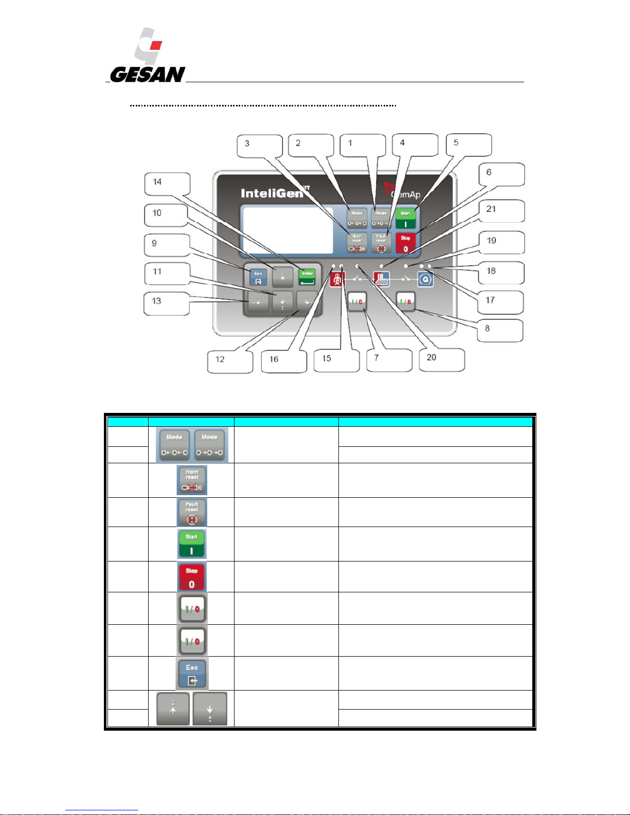
Picture 16- INTELIGENNTDigital Control Module
# SYMBOL DESCRIPTION IDENTIFICATION
(1)
Scrolls through different
operating modes
OFF←MAN←AUT←TEST
(2) OFF→MAN→AUT→TEST
(3) Deactivates audible alarm
(4) Fault reset Acknowledges faults and alarms
(5) Start button In manual mode
(6) Stop button In manual mode
(7) MCB ON/OFF Opens and closes MCB in manual mode
(8) GCB ON/OFF Opens and closes GCB in manual mode
(9)
Exit from actual screen
(without save changes if
editing)
(10)
Selects on-screen value, set
point, history record or
increase/decrease set point
value
Increases value
(11) Decreasesvalue
Page 42
RENTAL & SILENT ENERGY RENTAL GENSETS 4.3
41
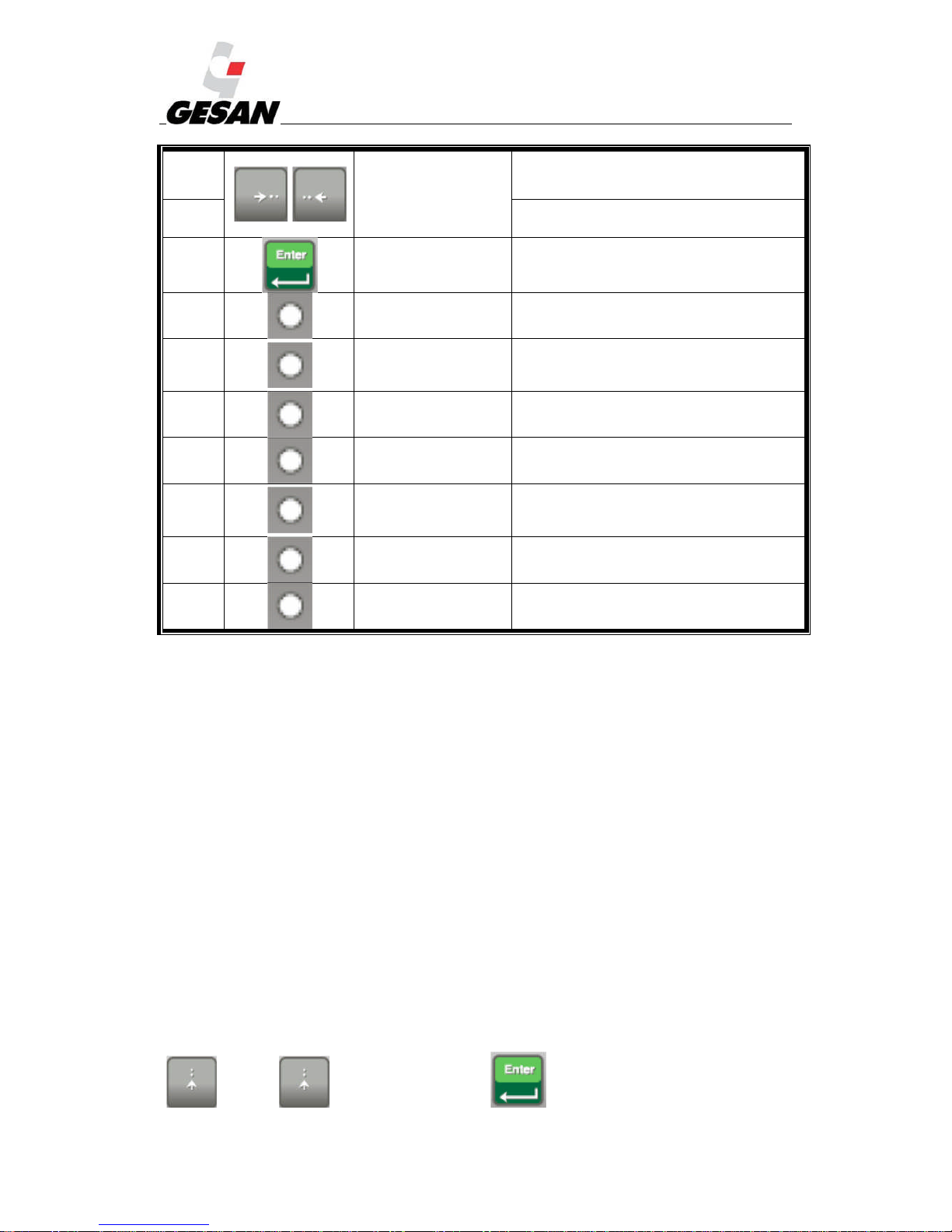
(12)
Moves history record
displayed columns to the
right/left, 5% increase/decrease
of edited set point, a value or
go out/into alarm list.
Increases value
(13) Decreasesvalue
(14) Enter button Confirms on-screen value
(15) Mains power status Green if mains power correct
(16) Mains failure
Red light flashes if mains failure occurs and generator set
doesn´t run; continuous if generator is operating, turns off
when Mains power restored.
(17) Generator voltage present Green led is on if unit voltage is present and within limits.
(18) Generator set failure Flashing Red LED indicates alarm
(19) State of GCB
Green led is on if GCB is closed. Flashes during
synchronization with mains.
(20) State of MCB
Green led is on if MCB is closed Flashes during reverse
synchronization with mains.
(21) State of bus Green led is on if bus voltage is correct
NOTE: GCB = Generator Circuit Breaker; MCB = Mains Circuit Breaker.
The InteliGenNTmodule contains a main menu screen and the following seven submenu screens:
Alarmlist
Measurement
Measurement I/O
History
Setpoints
User/Password
Languages
Pressing several times the main menu is displayed. To enter in a submenu, scroll up and down using
(10) or (11) buttons and press (14) button. To display the different
Page 43
RENTAL & SILENT ENERGY RENTAL GENSETS 4.3
42
instruments or parameters on each screen menu, press (10) or (11) buttons. To come
back to a previous menu screen, press (9) button.
The alarmlist screen display the alarms detected by the module. Pressing button (4) faults
and alarms are acknowledged.
The measurement screen displays the parameters measured on the engine; if the engine uses an
electronic management system, many additional parameters can be displayed. In addition to these
parameters, measurements can be displayed for fuel level, oil pressure, current, voltage, frequency, run
hours and battery charge level.
The measurement I/O screen display the status of digital inputs and outputs and the measured
parameter of analogue inputs (senders).
The history screen menu displays the log of alarms that have occurred in the generator unit. It also
logs the opening and closing of the mains circuit breaker as well as the starting and shutting down of the
generator unit.
The set points menu screen displays the adjustment parameters already configured; it is not
necessary to edit any of these.
The users/password screen allows to define users and passwords. The languages screen allows to
change the display language
AUTOMATIC mode (AUTO):
If a mains failure is detected, the InteliGenNTmodule will open the MCB (main circuit breaker).
Startup command is issued to generator set. If generator voltage is within the established limits, the LED
indicator (17) will be on and the control module closes the GCB (generator circuit breaker).
Once mains power has been restored, synchronization between mains and generator occurs; then the
MCB is closed, causing the generator to discharge, followed by the opening of the GCB. When mains
power is restored, there will be a period of time during which the engine continues operating at no load to
cool down before stopping completely.
Note: If (4) is pressed following a disconnection alarm, the engine could automatically start without any warning.
Page 44
RENTAL & SILENT ENERGY RENTAL GENSETS 4.3
43
NO-LOAD TEST mode (MANUAL):
Press the START button (5) to start up the generator set. When the generator voltage is
within the established limits, the LED indicator (17) will be on. To stop the unit, press STOP
(6).
LOAD TEST mode (TEST):
This operating mode is used for generator set start test is the mains is OK or to transfer the load to
the generator set when a mains failure is announced in advance. To stop this mode, change to another
mode by means of the buttons (1) or (2).
OFF mode:
The generator set will not start. Even if we press the buttons START (5), STOP (6)
, GCB ON/OFF (8), the generator will not respond.
Page 45
RENTAL & SILENT ENERGY RENTAL GENSETS 4.3
44
ALARMS:
The InteliGenNTcontrol module includes the following warnings:
INCIDENT STORED IN HISTORY RECORD
Startup sequence initiated Startup of Gen-Set
Shutdown of the Gen-Set Gen-Set stops
Electrical Generator circuit breaker closed GCB connected
Electrical Generator circuit breaker opened GCB disconnected
Some GCB in group was opened (in MINT) Other GCB trip
Mains circuit breaker closed MCB connected
Mains circuit breaker opened MCB disconnected
Time mode has been changed TimeModeChngd
STARTUP INFO
AMF Startup GenSetMF start
AMF Stop GenSetMF stop
Remote startup by binary input (SPM, SPtM) GenSetRemStart
Remote stop by binary input (SPM, SPtM) GenSetRemStop
System startup by binary input (MINT, MEXT) GenSetSysStart
System stop by binary input (MINT, MEXT) GenSetSysStop
Peak start (SPtM) GenSet PKstart
Peak stop (SPtM) GenSet PKstop
ENGINE
EVENT SPECIFICATION ALARM HISTORY
Electrical Generator Startup failure Sd Start Fail Sd Start Fail
Electrical Generator Overspeed Sd Overspeed Sd Overspeed
Electrical Generator Underspeed Sd Underspeed Sd Underspeed
SD Stop fail Sd Stop Fail Sd Stop Fail
Emergency Stop Emergency Stop Emergency Stop
RPM Pickup fail SdPickupFail SdPickupFail
Battery voltage warning Wrn Batt volt Wrn Batt volt
Battery is discharged Sd Batt flat 0
Page 46
RENTAL & SILENT ENERGY RENTAL GENSETS 4.3
45
GENERATOR
EVENT SPECIFICATION HISTORY
Generator phase 1 overvoltage Unl Vg1 Over
Generator phase 1 undervoltage Unl Vg1 Under
Generator phase 2 overvoltage Unl Vg2 Over
Generator phase 2 undervoltage Unl Vg2 Under
Generator phase 3 overvoltage Unl Vg3 Over
Generator phase 3 undervoltage Unl Vg3 Under
Generator Overfrequency Unl Fgen Over
Generator Underfrequency Unl Fgen Under
Generator voltage unbalance Unl Vgen Unbal
Generator overload UnlGen Overload
Load surge protection LoadSurge
Reverse power Unl Rev Pwr
Synchronization timeout Stp SyncTO
Ground fault protection Unl EarthFltC
Failure of generator circuit breaker GCB fail
Generator short circuit protection Unl Short Igen
Generator IDMT protection Unl IDMT
Generator current unbalance Unl Igen Unbal
Voltage on mains terminals (SPM) UnlCounterVolt
Bus voltage error (MINT) Unl BusMeasErr
PHASE SEQUENCE
EVENT SPECIFICATION ALARM HISTORY
Generator phase L1 is inverted GEN L1 neg 0
Generator phase L2 is inverted
GEN L2 neg
0
Generator phase L3 is inverted GEN L3 neg 0
Wrong generator phase sequence G ph opposed 0
Wrong generator phase sequence and
phase L1 is inverted
G ph + L1 neg
0
Wrong generator phase sequence and
phase L2 is inverted
G ph + L2 neg
0
Wrong generator phase sequence and
phase L3 is inverted
G ph + L3 neg
0
Mains phase L1 is inverted B L1 neg 0
Mains phase L2 is inverted B L2 neg 0
Mains phase L3 is inverted B L3 neg 0
Wrong mains phase sequence B ph opposed 0
Wrong mains phase sequence and phase
L1 is inverted
B ph + L1 neg
0
Wrong mains phase sequence and phase
L2 is inverted
B ph + L2 neg
0
Wrong mains phase sequence and phase
L3 is inverted
B ph + L3 neg
0
Page 47
RENTAL & SILENT ENERGY RENTAL GENSETS 4.3
46
7. MAINTENANCE OF THE GENERATOR SET
Ensure that the person doing this is trained to do so and uses suitable personal protection equipment.
7.1. BEFORE MAINTENANCE
You must:
Position the control board at STOP
Press the emergency button
Open the battery disconnector
To eliminate the grid voltage the control module receives to carry out its monitoring work, you must disconnect the
magnetothermic switch of 10 A located on the switchboard supplied by GRUPOS ELECTRÓGENOS EUROPA S.A If you are
using a switchboard from another manufacturer, ensure this cut-out is made before handling the generator set.
7.2. DURING MAINTENANCE
The preventive maintenance tasks are required for properly maintaining the material condition of
the equipment; this will result in an optimum operation. You must verify the following points:
1) With the engine cold, the oil level must be between the minimum and maximum value. If it is
lower, then the engine oil must be filled.
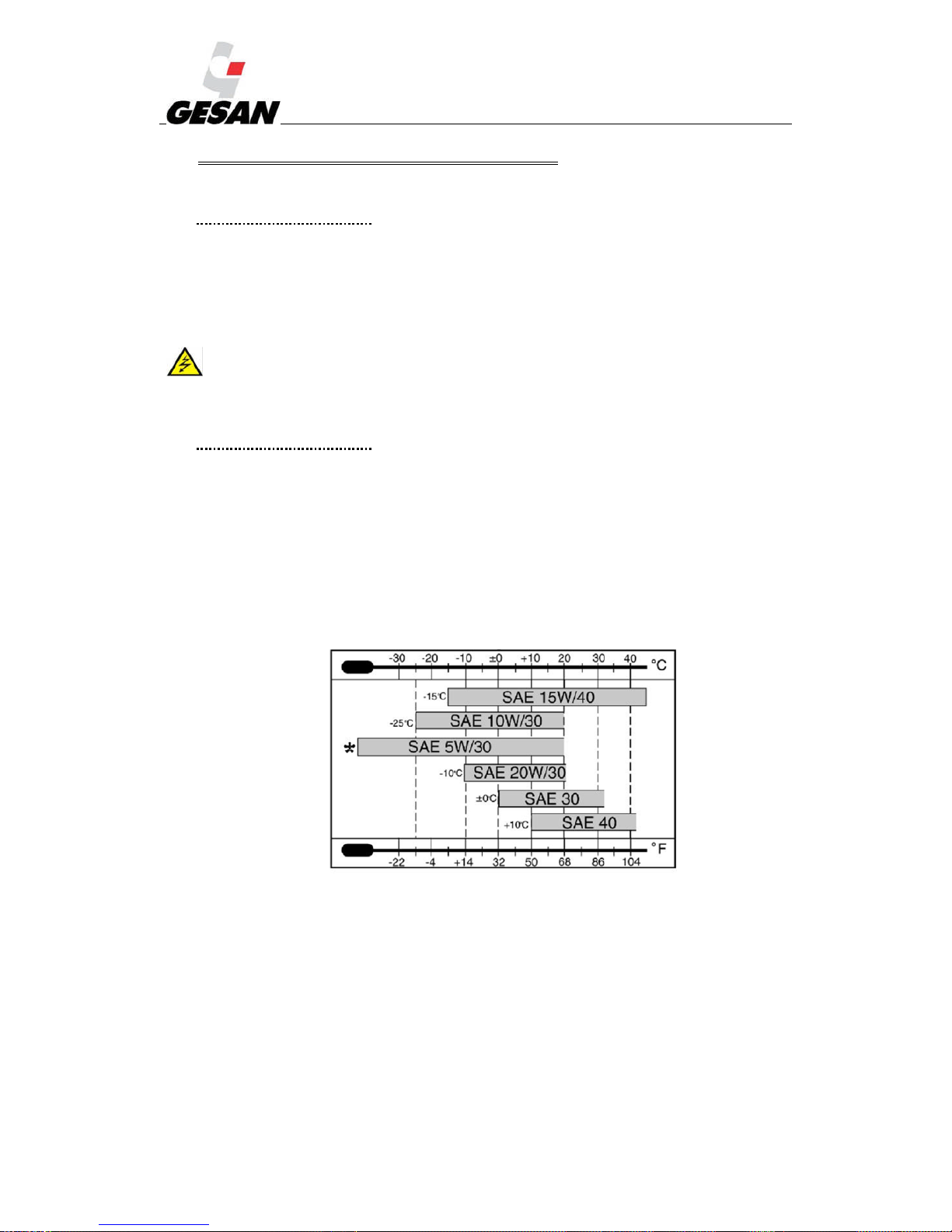
Note: The DEEP SEA 7310 and INTELIGEN boards will issue a warning to change the oil after 50 hours of service. The
recommended oil is 15W40.For temperature conditions other than those indicated, choose the type of fuel according to the
following table
Picture 17-Types of oil recommended according to temperature
2) The Engine oil level shall also be checked periodically. This will be accomplished by pulling out
the dipstick. It shall be carried out with the engine cold and in a horizontal position. If you wish
to check the oil level upon shutting down the Engine, wait for the housing to drain prior to
checking the oil level.
Page 48
RENTAL & SILENT ENERGY RENTAL GENSETS 4.3
47
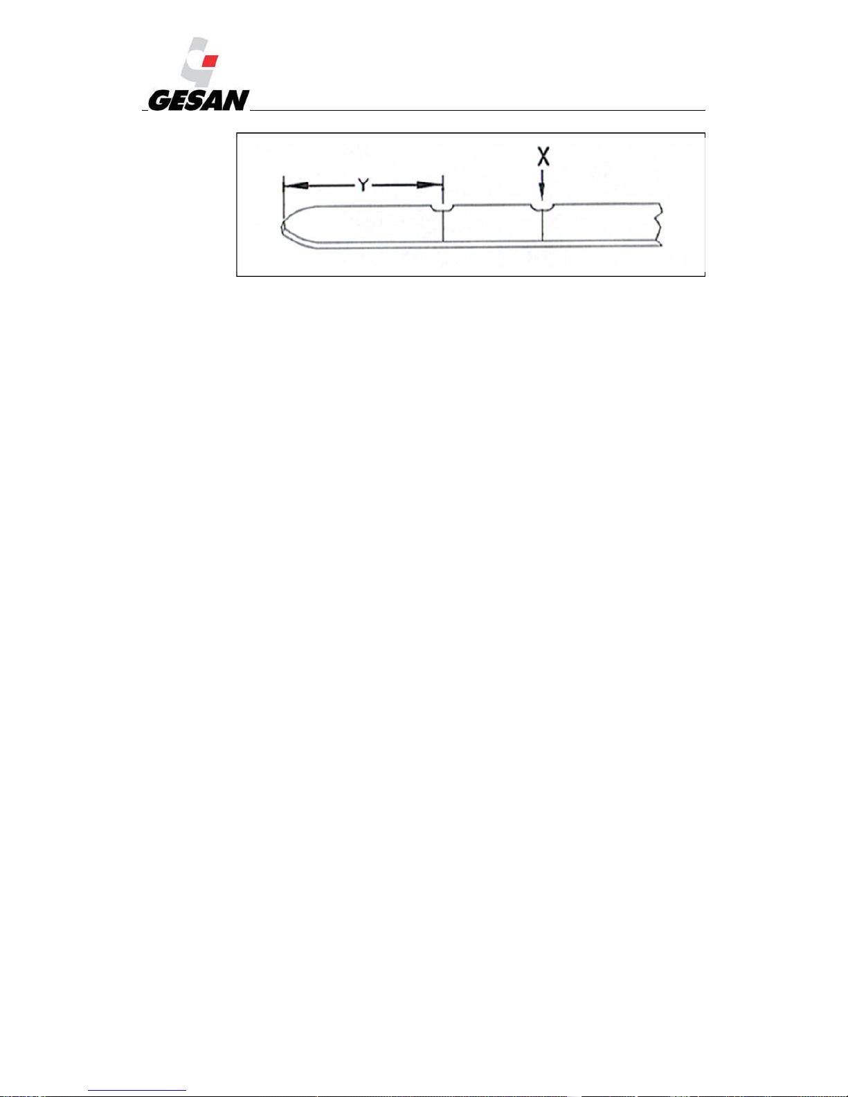
Picture 18 -Oil level dipstick.
The dipstick has two markings; a minimum oil level marking (Y) and a maximum oil level
marking (X). The recommended service level is between both markings.
If the oil level is below the minimum, the engine oil must be serviced. However, the oil level
shall never exceed the maximum level.
Unscrew the Engine’s oil filler plug; completely remove the plug in order to have free access to
the oil tank. Once serviced with oil, clean the oil tank cover and reinstall the oil filler plug. If the
engine oil must be replaced, first the engine oil must be drained. To accomplish this, the
generator set may include an external connection with a plug, from which the engine oil can be
drained; otherwise, the generator set must be opened and the engine oil shall be drained through
the lower plug located under the engine housing (refer to the engine manual delivered
separately). Once the engine oil is drained, re-install the plug that was removed and service the
engine oil as indicated for checking the oil level (refer to the engine manual, which is delivered
separately for this task).
Take into account the capacity of the tank where the used fluid is going to be poured and be
careful not to spill any fluid. Remember that the fluid is hazardous to the environment. Adopt the
necessary protective measures for handling the fluid; especially the use of protective goggles. If
fluid comes in contact with the skin, immediately wash the affected area.
3) The level of water in the radiator is correct.
4) The amount of fuel in the tank must be sufficient for the service that is to be provided by the
set. The DEEP SEA 7310 control module, housed in the control panel, has a fuel level
indicator.
5) Always refuel in a well-ventilated area with the engine turned off.
6) Visually inspect the connections and the electrical circuits of both switching and power.
7) Visually inspect for possible liquid leaks. If you detect any, locate their origin and resolve the
problem that has caused them.
8) The air outlets and inlets must be completely free so that the cooling air can circulate freely.
Page 49

RENTAL & SILENT ENERGY RENTAL GENSETS 4.3
48
9) Check the state of the unit’s radiator and clean if necessary. The Engine cooling fluid levels
shall be checked periodically, and shall be serviced if found below the minimum. The cooling
fluid used will be 50% ethylene glycol with a corrosion inhibitor (BS 658: 1992 or MOD
AL39) and 50% distilled water. To drain the engine cooling circuit, depending on the model,
the generator set may incorporate an external connection with a drain plug for that circuit;
otherwise, the draining must be carried out through the bottom part of the radiator. Servicing
with coolant once the circuit has been drained will be accomplished through the top part of
the radiator, through the radiator’s top plug, which is accessible through the covered openings
arranged on the generator set’s fairing. Take into account the capacity of the tank where the
used fluid is going to be poured and be careful not to spill any fluid. Remember that the fluid
is hazardous to the environment. Adopt the necessary protective measures for handling the
fluid; especially the use of protective goggles. If fluid comes in contact with the skin,
immediately wash the affected area.
For further information, refer to the engine manual, which is delivered separately.
10) Make sure the exhaust tube is not obstructed.
11) Check in the battery connection terminals and the level of electrolyte (if necessary add
demineralised or distilled water). Never add acid. The battery must be charged if the voltage
in the terminals is below 12.3 V.
12) If you wish to recharge the battery after having removed it from the unit, remove the plugs
and recharge with direct current only. The charger’s positive (+) cable is connected to the
battery’s positive (+) cable and the charger’s negative (-) cable is connected to the battery’s
negative (-) terminal. Recharge with a current equal to 1/10 of the nominal capacity (Ah). The
battery is completely charged when the density of the acid is 1.28. Before finishing charging
turn off the charger before disconnecting the battery and check the level of electrolyte.
13) If the battery is discharged and you wish to carry out an emergency start with another battery
from another generator set, first check the tightness of the discharged battery's terminals. Stop
the engines of the two units and first connect the two positive terminals of the batteries and
then the negative terminal of the charged battery with a metal area of the faulty unit (earth).
Start up the auxiliary unit and then the unit to repair. Disconnect the cables in reverse order to
avoid short circuits. Finally recharge the battery completely.
14) Do not operate under any circumstances the genset with open doors. Risk of electrical shock,
burns or entrapment. Make sure doors are locked group prior to implementation.
15) The incorporation of the water separator in all the units means you must monitor the water in
it and bleed it depending on how full it is. This is not particularly inconvenient as all you have
to do is monitor the transparent tank to decide when to bleed it. If the filter has reached the
end of its service life, replace it completely.
16) The oil vacuum pump is an improvement when draining the tank, thus saving time and
facilitating maintenance.
Page 50
RENTAL & SILENT ENERGY RENTAL GENSETS 4.3
49
17) The fuel tank includes a cleaning record for quick access and a safety key to avoid fuel theft
through the output connector on the bedplate.
18) The radiator is drained through the bedplate connector.
19) For maintenance of the casing, it is recommended to wash it occasionally in order to avoid the
accumulation of dirt. Its galvanised bodywork prevents corrosion and rusting.
Note: Preventive maintenance tasks are recommended, using goggles and gloves for all operations in which battery acid is
handled.
Note: Remember that all the operations shall be carried out as carefully and safely as possible, as indicated in this manual.
(Take special care with the risks of short circuits that can be caused by contact with metal objects in the unit).
7.3. MAINTENANCE TABLE
PERIODICITY MAINTENANCE TASK
MONTHLY
Perform a simulation of an electrical grid failure: the unit should supply the consumers for
1 hour.
For systems with multiple generator sets in parallel, check the coupling and the distribution
of the loads.
Check the connections of the starter battery; clean and coat with Vaseline.
Ensure the battery charger is working correctly.
Verify the fuel level in the main tank.
Verify the levels of coolant and oil.
Verify that all the lights on the switchboard function correctly.
Check that the switching works correctly in the transfer.
Check and verify all the dials and indicators on the switchboard.
Consult the manufacturer's manual for the engine and alternator for specific tasks.
EVERY SIX
MONTHS
Start up the engine manually 3 times; each time note the readings of voltage and density of
each element of the battery. If any of the voltage readings differs significantly from those of
the other elements of the battery, do not carry out the remaining manual start-ups.
Fully charge the battery and verify the level of electrolyte.
Verify that the cooling pipes are not leaking.
Check that all the alarms of the unit are displayed correctly.
Consult the engine manufacturer's manual for specific tasks.
EVERY YEAR
Clean the exterior of the fuel tank, verify the fuel and coolant transport pipes and replace if
necessary.
Clean the radiator and top up with antifreeze.
Verify that the measuring instruments show correct measurements.
Clean the control panel and re-tighten the connections.
Verify the antivibration elements, connectors and belts are in good condition.
Check that the vibrations and noise are within the standard values.
Consult the manufacturer's manual for the engine and alternator for specific tasks.
EVERY 3
YEARS
Replace the starter batteries
Page 51

RENTAL & SILENT ENERGY RENTAL GENSETS 4.3
50
Notes:
Consult the manuals for the engine and alternator for specific maintenance tasks.
Ensure the maintenance is performed by qualified staff.
Ensure you comply with the local legislation on environmental protection. Any batteries, filters, liquids
and electrical equipment that have been replaced and any packaging must be sent to an authorised
recycling centre.
* When cleaning the generator set, do not use pressurised water as it could damage components.
Page 52
RENTAL & SILENT ENERGY RENTAL GENSETS 4.3
51
8. SOLUTION OF BREAKDOWNS
INCIDENT PROBABLE CAUSE SOLUTION
In the switchboard
The engine
does not start
The starter motor does
not turn
1.-Battery defective 1.-Change the battery
2.-Starter system defective
2.-Replace the starter system
3.-Contact the technical service
The starter motor works
correctly
1.-Voltage detector of the
control module damaged
1.-Contact the technical service
2.-Lack of fuel
2.-Fill the fuel tank
The engine starts
It stops with reason
1.-There has been an
emergency
1.-Take the appropriate measures
It stops without apparent
reason
1.-Emergency not indicated
due to a fault with the LED
indicator
1.-Contact the technical service
It does not stop when
there is an emergency
1.-Shut-down system
defective
1.-Press the emergency button
2.-Contact the technical service
The generator set does
not stop when in the stop
position
1.-Control module
damaged
1.- Press the emergency button
2.-Shut-down system
defective
2.-Contact the technical service
From inside the unit
Unit running
High voltage at no load
1.-Excessive speed
1.- Contact the technical service
2.-Fault in the alternator
Low voltage at no load
1.-Insufficient speed
1.- Contact the technical service
2.-Fault in the alternator
Voltage correct but low
with load
1.-Excessive loads
1.-Reduce the loads of the unit
2.-Insufficient speed with
load
2.- Contact the technical service
3.-Fault in the alternator
Voltage unstable
1.-Voltage meter damaged
1.- Contact the technical service
2.-Engine speed unstable
3.- AVR damaged
Strange noise inside the
unit
1.-Various causes
1.-Verify that there is nothing stopping the
unit from functioning correctly.
2.- Contact the technical service
9. PROTECTION OF THE ENVIRONMENT
Once the generator set has been installed, clean up the packaging, accessories, electric tools, etc. that
were necessary for its full installation.
When you wish to dispose of the batteries according to the environmental regulations, it is
recommended that the batteries be turned into an authorized recycling centre.
For an improved environment, recycle as much as possible and do not throw electrical components out
with the rubbish, according to European Directive 2002/96/CE. These must be set aside so they can be
subjected to an environmental safe recycling.
Page 53

RENTAL & SILENT ENERGY RENTAL GENSETS 4.3
52
10. WARRANTY
The warranty of the generator set is extended for a calendar year from the date it is commissioned.
This must be reported to GRUPOS ELECTRÓGENOS EUROPA S.A, (hereafter the manufacturer)
in writing, whether by fax, or e-mail. The data that must be communicated is the MODEL
NUMBER, SERIAL NUMBER AND COMMISSIONING DATE.
If the manufacturer is not notified of the commissioning within a maximum period of sixty days
from the invoice date, then the invoice date itself will be used as the effective start date of the
warranty period. If for any reason the commissioning cannot be performed in the sixty days
following the invoice date, the manufacturer must be informed of this in writing. This extension of
the warranty is subject to the acceptance of the end supplier of the engine and alternator. This shall
never exceed 120 days from the invoice date. This acceptance shall be sent by staff of GRUPOS
ELECTRÓGENOS EUROPA S.A The warranty covers defects in components and assembly, not
due to improper use, manipulation, modification or insufficient maintenance. The warranty does not
cover failures caused by use of the generator set with other devices that have not been installed or
supplied by the manufacturer. Also excluded are any failures and damages caused by prolonged or
improper storage. In this last case, refer to the manufacturer’s user manuals. The warranty for the
generator set ONLY covers spare parts and labour required for operating the set by personnel
authorized by the manufacturer. Travel, and other expenditures derived from the repairing of a set
under warranty are excluded from the warranty coverage therefore, under no circumstance shall the
manufacturer cover these expenses, which must be paid for in full.
The decision to accept or deny a warranty claim will be made by the manufacturer. Regarding
engine and alternator failures, the warranty will be granted by the supplier of these components in
accordance with their warranty conditions. The manufacturer reserves the right to require that the
faulty component be returned to them. In this case, all expenses arising from this recovery shall be
covered by the customer until the resolution of the warranty. If the warranty is accepted, the
transport costs of this return shall be paid provided the cost is not greater than that caused by
shipping the material in advance. Any repair made within the warranty period shall not lead to the
modification of expiry date for the generator set warranty.
The warranty does not cover damages caused by terrorist acts, natural disasters, sabotages or similar
occurrences. If any of the stated provisions does not comply with the legislation of a specific
country, the importer is required to notify the manufacturer prior to executing the purchasing-sale
operation.
This warranty expressly replaces all other warranties, explicit or implicit, including any warranty
that is commercial or suitable for personal use. The warranty presented here is for exclusive use in
resolving claims based on defects and non-conformities in generator sets, regardless of whether the
claim is based on a contract or grievance, and replaces other resolutions, responsibilities or rights,
whether or not they arise by law.
Page 54
RENTAL & SILENT ENERGY RENTAL GENSETS 4.3
53
11. NOISE LEVEL
GRUPOS ELECTRÓGENOS EUROPA S.A. generator sets have different acoustic levels
depending on the power and the sound proofing of the generator set. The acoustic power is indicated on a
sticker on the generator set bedplate.
Each generator set is supplied with a sticker indicating the level of acoustic power generated (see
ANNEX 1 PICTOGRAMS). The noise was measured according to European Directive 2000/14/CE and
in compliance with the maximum values determined by Directive 2005/88/CE.
Commercial reference
Sound levels
LWA dBA@7m
DPR 20
90 60
DPR 30 / DPR 30 NC
90 60
DPR 45 / DPR 45 NC
94 64
DPR 60 / DPR 60 NC
94 64
DPR 80 / DPR 80 NC
94 64
DPR 100
97 67
DPR 250 NC
97 67
DPR 500 NC
98 68
DVR 140 NC
97 67
DVR 150
97 67
DVR 200 NC
97 67
DVR 250 NC
97 67
DVR 315 NC
97 67
DVR 400 NC
97 67
DVR 460 NC
98 68
DVR 500 NC
98 68
DTR 250
97 67
DTR 275
97 67
DTR 300
97 67
DTR 400
98 68
DTR 450
98 68
DTR 500
98 68
Note: If you are continuously carrying out your work near the equipment, it is recommended that you use hearing protection.
12. DECLARATION OF CONFORMITY
In conjunction with the unit, GRUPOS ELECTRÓGENOS EUROPA S.A shall deliver “Declaration
of CE conformity” sheet, complying with the regulations or standardised documents to which it refers.
Page 55
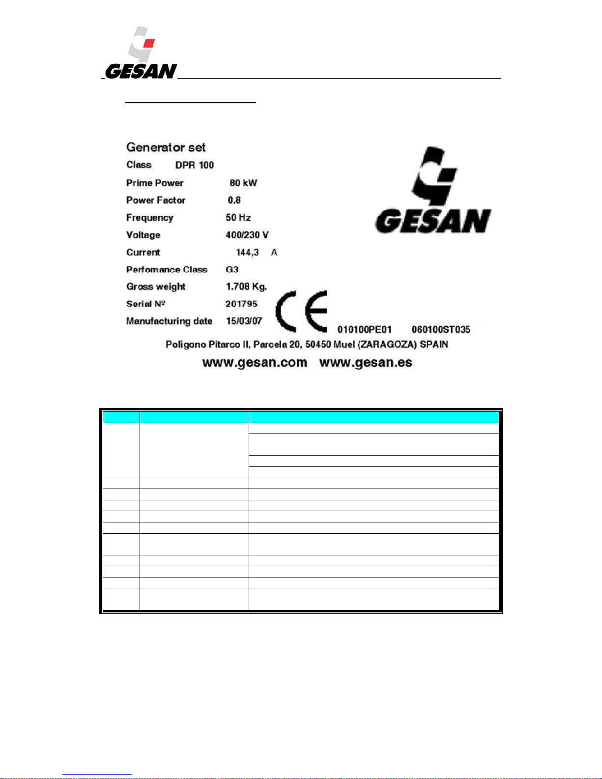
RENTAL & SILENT ENERGY RENTAL GENSETS 4.3
54
13. ANNEX 1: PICTOGRAMS
Details of the unit's identification plate:
Picture 19- Identification plate
NO. NAME DESCRIPTION
(1) DPR 100
D => The engine fuel is diesel 1,500 rpm.
P => The engine manufacturer is (P)erkins, (V)olvo, (C)ummins
or Deut(Z)
R => The generator set is Rental
100 => Commercial name.
(2) Nominal power Nominal power of the engine expressed in kW.
(3) Power factor Indicates the power factor of the alternator.
(4) Nominal frequency Nominal frequency of the generator set (Herz).
(5) Nominal voltage Nominal voltage of the generator set (Volts).
(6) Execution class
When the engine bears an overload it reacts with catalogued
times, according to ISO 8528.
(7) Weight Total weight of the generator set.
(8) Serial No. Serial number for the manufacture of the set.
(9) Date of manufacture Date of manufacture of the generator set.
(10)
The CE marking indicates that the generator set complies with all
the relevant directives.
Page 56
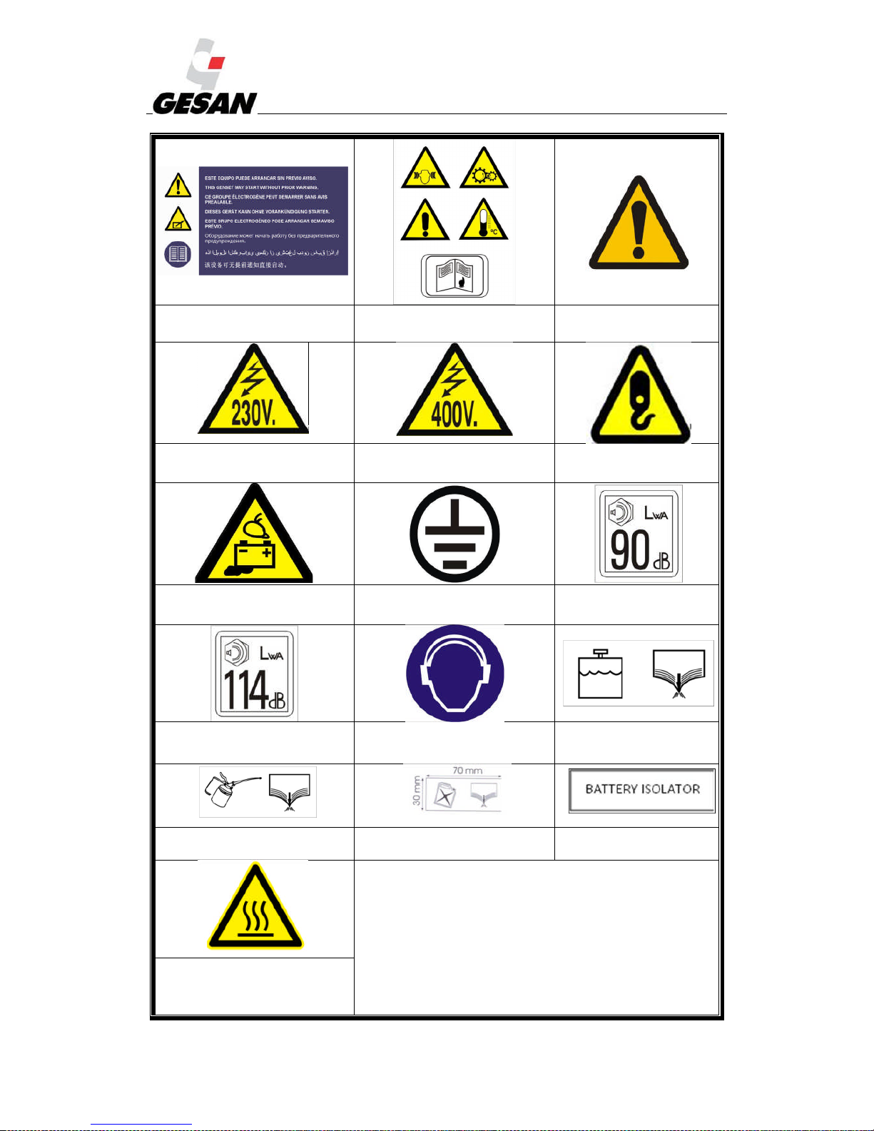
RENTAL & SILENT ENERGY RENTAL GENSETS 4.3
55
Picture 20 This genset may start without
prior warning
Picture 21 General warning
Picture 22 Unknown hazard
warning
Picture 23 230 volt electrical hazard Picture 24 400 volt electrical hazard Picture25 Lifting point
Picture26 Possible battery spill Picture27Earthing connection Picture28 Noise level 90 dB
Picture29 Noise level 114 dB
Picture30 Mandatory use of hearing
protection
Picture31 Coolant drainage
Picture32 Oil drainage Picture33 Fuel drainage Picture 34 Battery isolator
On hot surfaces where it has not been possible to minimize the
risk of burns, the following warning pictogram will be installed.
Picture 35:High temperature
Page 57
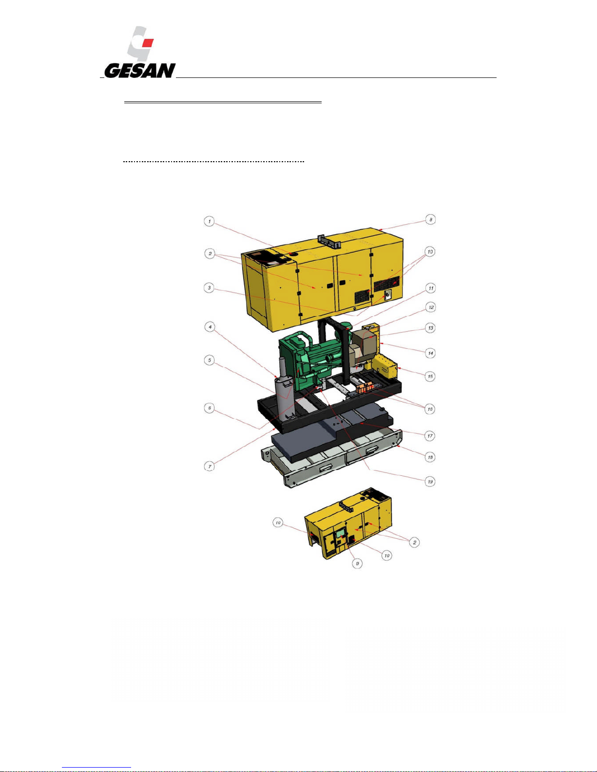
RENTAL & SILENT ENERGY RENTAL GENSETS 4.3
56
14. ANNEX 2: SILENT-ENERGY RENTAL:
If you have been supplied with a SILENT ENERGY RENTAL generator set, all the information in
this manual applies to this model except in the following sections:
14.1.DESCRIPTION OF THE GENERATOR SET
A general description of the SILENT ENERGY RENTAL generator set manufactured by GRUPOS
ELECTRÓGENOS EUROPA S.A and its different configurations can be found below.
Picture 36-Inside a soundproofed generator set
1) Coolant filler trap
2) Side access doors
3) Fuel tank filler cap
4) Exhaust silencer
5) Engine
6) Antivibration mounts
7) Bedplate
8) Casing
9) Switch board door
10)
Air inlet
11) Elevation gantry
12) Switchboard
13) Alternator
14) Power panel
15) Socket panel Silent Energy Rental
16) Batteries
17) Bedplate with fuel tank
18) Liquid collection tray
19) Sections supporting generator set on bedplate
Page 58
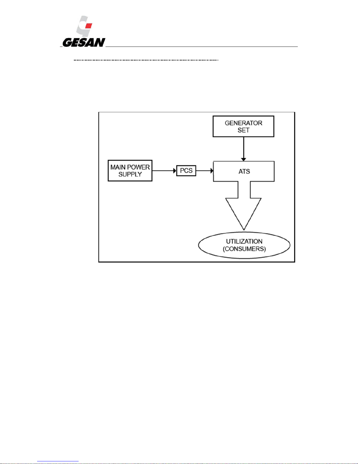
RENTAL & SILENT ENERGY RENTAL GENSETS 4.3
57
14.2.VARIATIONS IN THE ELECTRICAL CONFIGURATION:
The generator unit can be supplied:
With automatic switchboard
Without automatic switchboard
Picture 37-Switchboard diagram
Note: I.C.P.: Power regulator switch
Page 59

RENTAL & SILENT ENERGY RENTAL GENSETS 4.3
58
14.3.VARIATIONS IN THE CONTROL INSTALLATION:
The control installation can be carried out in three different ways:
1) The switchboard has been supplied by GRUPOS ELECTRÓGENOS EUROPA S.A
2) The switchboard has not been supplied by GRUPOS ELECTRÓGENOS EUROPA S.A
3) The unit is of the “Emergency by signal” type
14.3.1. Switchboard supplied by GRUPOS ELECTRÓGENOS EUROPA S.A
Connect the R S T N terminals and the terminals numbered 37, 40, 41, 44 (with GECO control
module also connect 45, 46 and 47) of the control panel installed in the set to the terminals of the
switchboard numbered in the same way.
ATTENTION: Do not confuse the control terminals R S T N with the power terminals R S T N (see the connections diagram
preceding the control and power installation explanations).
To carry out these connections you must use a conductor with eight 1.5 mm² wires (11 wires with
the GECO module). This cable is not supplied with the generator set. The maximum distance between the
control panel and the switchboard shall be 25 m for a section of 1.5 mm² and a power of 650 kVA. For
greater powers and distances you must calculate the section of the cable to avoid an excessive voltage
drop.
The switchboard can be supplied as an option with units manufactured by GRUPOS
ELECTRÓGENOS EUROPA S.A (see point 3.3); if it is not supplied this switchboard must be
supplied by the customer.
The switchboard consists of electrical switchgear. This switchboard shall avoid simultaneous
supply by the electrical grid and generator set.
There are three types of electrical switchgear used in the automatic switchboard supplied by
GRUPOS ELECTRÓGENOS EUROPA S.A:
Page 60
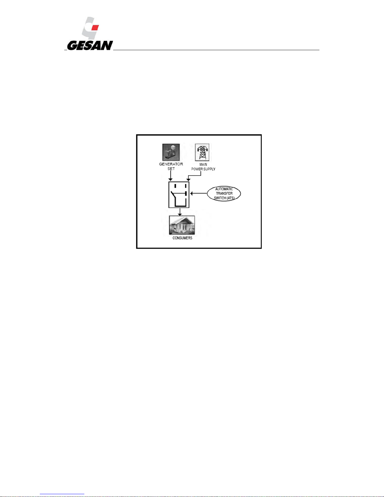
RENTAL & SILENT ENERGY RENTAL GENSETS 4.3
59
Contacts: mechanically and electrically interlocking. They are used when the nominal current is
between 40 and 125 A.
Motorised switches: used from 160 A to 3200 A.
Motorised circuit breakers: mechanically and electrically interlocking. Supplied when requested by
the customer.
The following diagram shows the functioning of a switchboard:
Picture 38- Switchboard diagram
The electrical installation of the switchboard is divided in two parts: firstly the control part
must be installed (electrical grid monitoring and management and switching) and secondly the power
part (transmission of electrical energy).
14.3.2. Switchboard not supplied by GRUPOS ELECTRÓGENOS EUROPA S.A
Consult the user manual of the corresponding switchboard and follow these steps.
Connect the terminals R S T N of the control panel (reference voltage of the electrical grid) to the
supply input of the electric company.
Connected the terminals numbered from 37 to 47 (both inclusive) to the control wiring of the
switchboard (consult the electrical diagram of the generator set panel).
Ensure that the electrical and mechanical interlocking has been correctly executed. Ensure that the
switchboard you wish to install is compatible with the generator set supplied. Typical assembly is
with contacts. For motorised switches consult GRUPOS ELECTRÓGENOS EUROPA S.A
The section of the conductor must be suitable for your installation.
Page 61

RENTAL & SILENT ENERGY RENTAL GENSETS 4.3
60
14.3.3. “Emergency by signal” generator set:
The generator set will not monitor the electrical grid nor control the switching, as this must be
controlled by the user's management system.
The terminals through which the generator set receives the start-up signal are 184 and 185, and must
be activated by a potential-free contact.
For terminals 120 and 121 the generator set returns a potential-free signal when its voltage and
frequency are correct.
The terminals R S T N must be connected to the electrical grid at a point prior to the switchboard:
the power for the engine block heater and battery charger is received through them. The section of the
conductor must be suitable for your installation.
14.3.4. POWER installation:
The connection diagram is shown in the picture.
The power installation can be carried out in two ways:
1) The switchboard has been supplied by GRUPOS ELECTRÓGENOS EUROPA S.A
Connect the U V W N outputs of the generator with the U V W N terminals of the switchboard.
Connect the ICP of the electric company to the R S T N terminals.
Connect the X Y Z N terminals of the switchboard to your installation.
2) The switchboard has not been supplied by GRUPOS ELECTRÓGENOS EUROPA S.A or the
generator set is of the “emergency by signal” type.
Connect the U V W N output of the generator to the input of the switchboard. Consult the manual of
your switchboard.
This installation must be executed by qualified staff, adapting the section of the conductor to the
distance and the power transported.
Remember that the earthing connections must be made according to the current regulations.
14.4.ATYS SWITCHES:
The switches are a type of electrical switchgear especially designed for grid transfer systems that
simplify the equipment and the necessary control wiring.
The connection terminals of the switches are organised as follows:
- Upper terminals: for connecting the consumers.
- Lower left terminals: for connecting the electrical grid.
- Lower right terminals: for connecting the generator set.
You can find a connections diagram on the switch casing.
The switches can also be operated manually. They include a lever for grid transfer in the event of
emergency when there is no source available.
Page 62
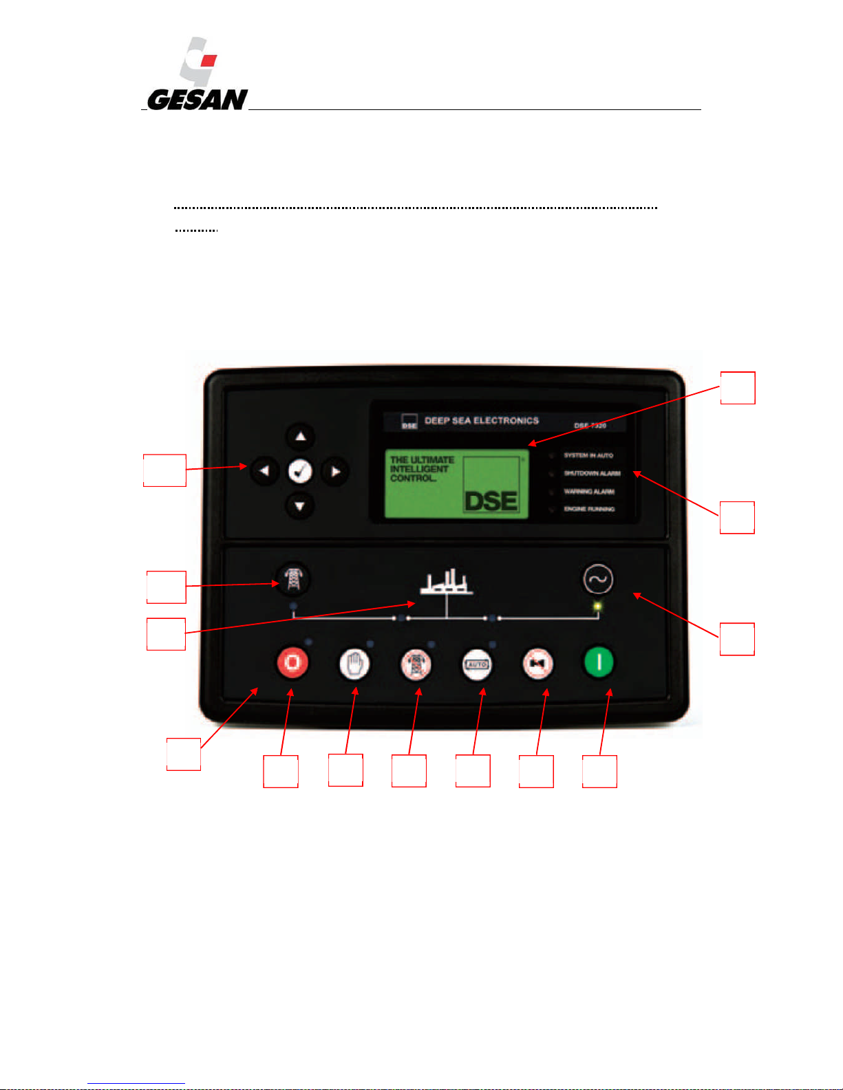
RENTAL & SILENT ENERGY RENTAL GENSETS 4.3
61
As a safety guarantee, the switches may be locked in position 0 with a padlock (thus manual
operation is impossible and the electrical controls are disabled.
If you need additional information, consult the manual of the switch manufacturer.
14.5.ADDITIONAL COMPONENTS SUPPLIED WITH THE SILENT ENERGY RENTAL
UNITS:
14.5.1. DEEP SEA 7320 Digital Control MODULE
In the SILENT ENERGY RENTAL sets, DEEP SEA 7320 scheduled board programmed for DC
operation is replaced with the DEEP SEA 7320 board that allows running in an emergency if there is a
grid failure.
Picture 39- Deep Sea 7320 control module
1
2
3 4
5 6
7
8
9
10
11
12
A
Page 63
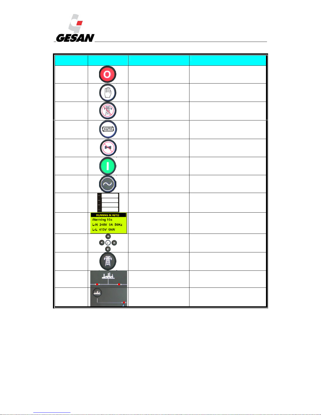
RENTAL & SILENT ENERGY RENTAL GENSETS 4.3
62
NUMBER SYMBOL DESCRIPTION IDENTIFICATION
(1) Stop button Red LED
(2) Manual mode button Red LED
(3) Test mode button
Green LED (available only in model
7320)
(4) Automatic mode pushbutton Red LED
(5)
Alarm silencer/test button
for lights
(6) Start pushbutton
(7)
Button to “force the
generator set”
Green LED when the generator set is
available
(8) Definable LED indicators Red LED
(9) Display of parameters
(10) Menu navigator
(11) Button to “force the grid”
Green LED (available only in model
7320)
(12) Switchboard status
Left red LED: grid supplying the
loads / right red LED: Generator set
supplying the loads
(A)
Button to “open the
generator set”
Red LED: generator set supplying
the loads
The Deep Sea 7320 control module is an automatic module that monitors the supply of the electrical
grid and, if this fails, will start up the generator set. This control module also has the option of starting up
manually.
Page 64
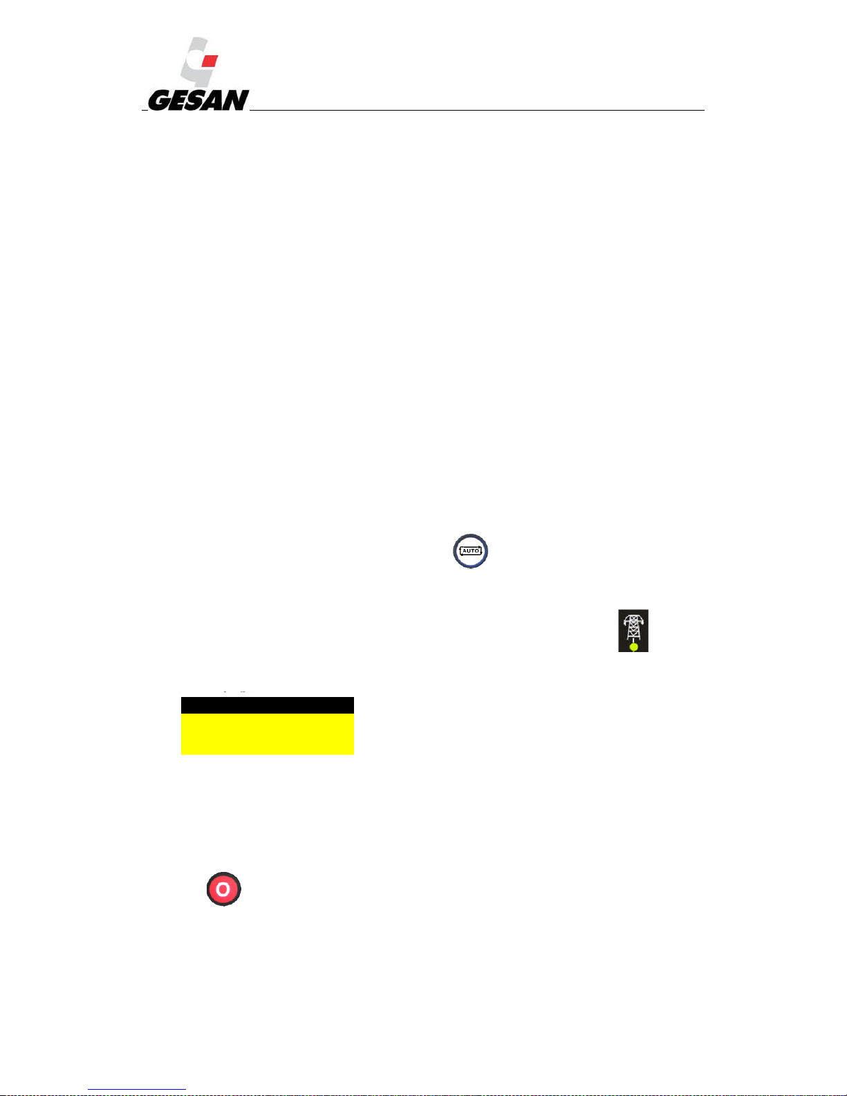
RENTAL & SILENT ENERGY RENTAL GENSETS 4.3
63
Case 1: Manual operation:
Step 1: Make sure the switch is in the OFF position
Step 2: Close the battery disconnector.
Step 3: Start up the generator set, pressing button 1.
Step 4: Once the generator set is ready to load, close the switch.
Step 5: To be able to stop the generator set again press button 0.
Step 6: Disconnect the battery.
Case 2: Automatic operation:
Step 1: Make sure the switch is in the OFF position
Step 2: Close the battery disconnector.
Step 3: If there is an alarm, reset it with button 0 (once resolved).
Step 4: Toggle the switch to the ON position.
Step 5: Press the automatic mode button.
Case 3: Manual to automatic mode without stopping.
The user has the possibility of controlling all the generator equipment parameters as well as the
status of the electrical grid power supply. This module is supplied with automatic type generator sets with
or without switchboards.
AUTOMATIC (Auto) mode:
This is the usual operation mode.
Manual mode is activated when you press button (4). The LED of the upper part of the
button will light up indicating that it is operational.
(7320) If the electric grid supply fails for longer than the configured time, the LED (11), that
indicates the electrical grid is available, goes off.
When the mains electricity returns, the engine will continue working at no load for a period of time
to cool before stopping completely.
If during the period of work at no load (cooling period) a new mains failure occurs, the generator set
will not take the charge again.
Press (1) or the emergency button to stop the unit intentionally.
MANUAL mode:
Alarm
Stop
Start-up failure
Page 65
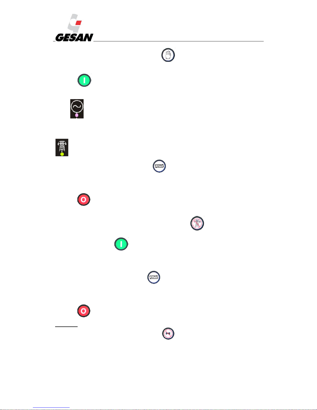
RENTAL & SILENT ENERGY RENTAL GENSETS 4.3
64
The manual mode is activated when pushbutton (2) is pressed. The LED of the upper part of
the button (2) will light up indicating that it is operational.
Press (6) to start up the unit.
If the mains fails, a remote start-up signal is received or the button to “force the generator set” is
pressed (7),the loads will be transferred to the generator set (module 7320: the unit will continue
working at load regardless of the condition of the electrical grid).
The loads may be transferred back to the electrical grid by pressing the button to “force the grid”
(11).
To end this operation mode press the button (4).
Once you have pressed the button (4) when there is a correct supply from the electrical grid (without
the remote start-up signal being activated), the stopping process described in automatic mode will begin.
Press (1) or the emergency button to stop the unit intentionally.
TEST mode (7320):
This operation mode is selected when you press the button (3). It is used to check the
generator set is functioning correctly.
Press the start-up button (6) to start the generator set.
In this working mode a failure in the electrical grid is simulated, transferring the loads to the
generator set.
To complete this mode press the button (4). If there is a correct supply from the electrical
grid (without the remote start-up signal being activated), the stop process described in the automatic mode
will begin and the loads will be transferred to the electrical grid.
Press (1) or the emergency button to stop the unit intentionally.
ALARMS:
When an alarm occurs, you can press the button (5) to silence the acoustic warning and turn
off the LED indicator (8).
By default the display shows the status screen, and when an alarm occurs it will be shown as
follows:
Page 66
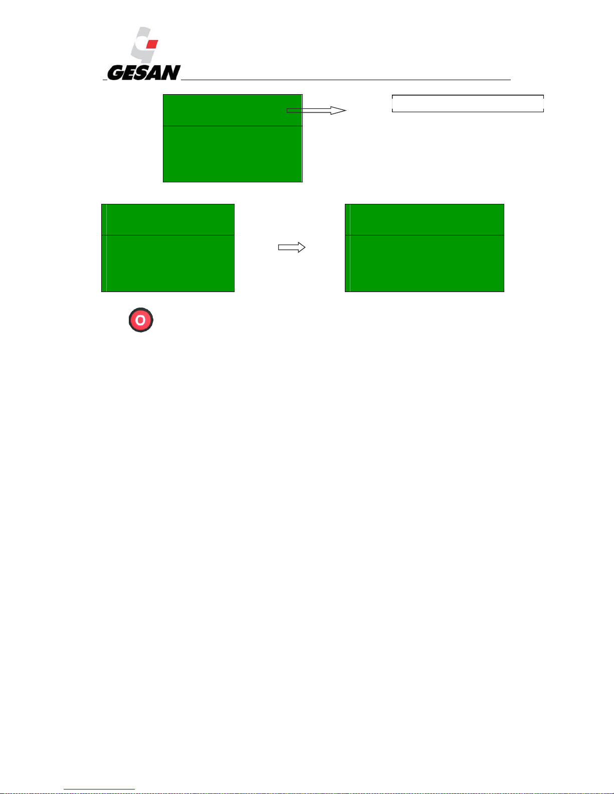
RENTAL & SILENT ENERGY RENTAL GENSETS 4.3
65
If the unit stops due to an alarm, while a warning is enabled, all the alarms will be shown cyclically:
Alarm 1/2 Alarm 2/2
Warning
Low oil pressure
Stop
High coolant temperature
The warnings do not mean the generator will stop.
Press (1) to reset the alarms that cause the stoppage. If the cause of the alarm has not disappeared,
you cannot reset the board.
Alarm 1/2
Warning
Low oil pressure
Alarm 1 of a total of 2 present
Page 67
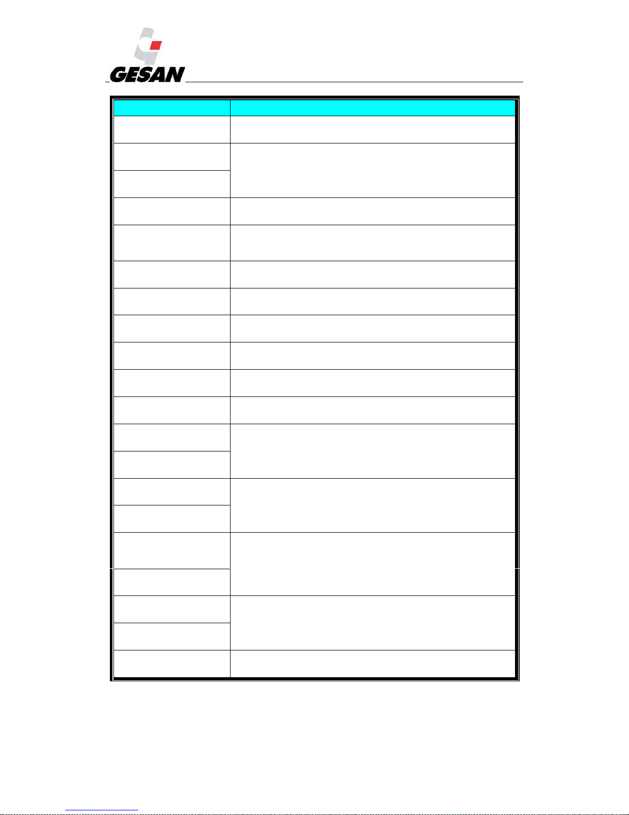
RENTAL & SILENT ENERGY RENTAL GENSETS 4.3
66
INCIDENT DESCRIPTION OF THE ALARM
ALARM
Warning
Battery charge failure.
No voltage is detected in the battery charge alternator.
ALARM
Warning
Low battery voltage
Battery voltage out of range.
ALARM
Warning
High battery voltage
ALARM
Warning
Failure to stop
After a command to stop the engine continues to
function. It may
indicate a fault in the oil pressure sensor
ALARM
Warning
Auxiliary inputs
The auxiliary inputs can be configured and will show the message
indicated by the user.
ALARM
Warning
Low fuel level
The fuel level is below the limit.
ALARM
Warning
CAN ECU fault
The engine's electronic control unit has detected an alarm and this is
indicated for screen (electronic engines only).
ALARM
Warning
kW overload
The power (kW) generated is above the limit.
ALARM
Warning
Earthing current fault
The earthing current is above the limit (optional).
ALARM
Warning
Negative line sequence
Indicates a current imbalance in the generator.
ALARM
Warning
Low oil pressure
Engine oil pressure is below the limit.
ALARM
Warning
High engine temperature
Engine temperature outside the limits.
ALARM
Warning
Low engine temperature
ALARM
Warning
Low speed
Engine speed outside the limits.
ALARM
Warning
Overspeed
ALARM
Warning
Low generator
frequency
Generator frequency outside the limits.
ALARM
Warning
High generator frequency
ALARM
Warning
Low generator voltage
Generator voltage outside the limits.
ALARM
Warning
High generator voltage
ALARM
Warning
Emerg. overcurrent
Generator current above the limits.
Page 68
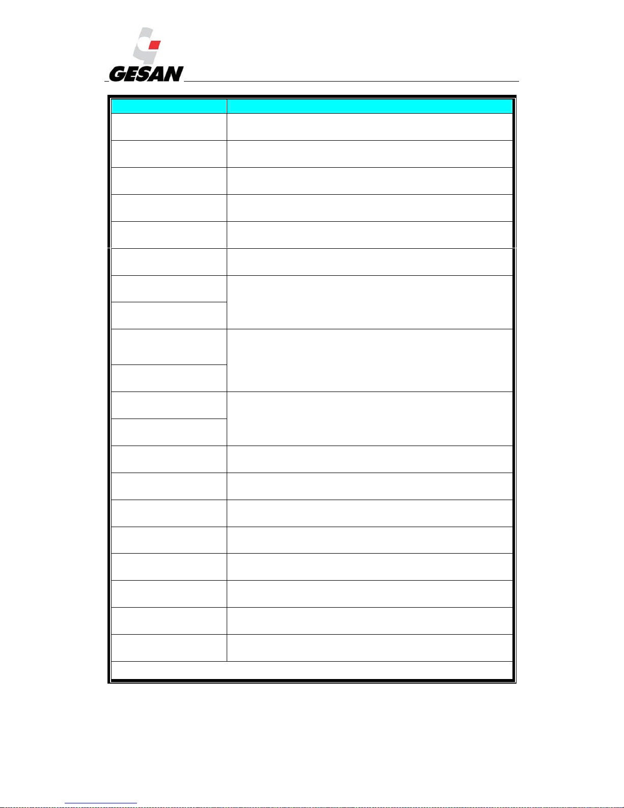
RENTAL & SILENT ENERGY RENTAL GENSETS 4.3
67
INCIDENT DESCRIPTION OF THE STOPPAGE
ALARM
Stop
Earthing current fault
The earthing current is above the limit (optional).
ALARM
Stop
Start failure
The engine has not started after three tries.
ALARM
Stop
Emergency fault
The emergency stop button has been pressed. The generator will not be
available until the emergency button is unlocked.
ALARM
Stop
Low oil pressure
Engine oil pressure below the limit.
ALARM
Stop
High engine temperature
Engine temperature above the limit.
ALARM
Stop
Line sequence
Line sequence different from that selected.
ALARM
Stop
Low speed
Engine speed outside the limits.
ALARM
Stop
Overspeed
ALARM
Stop
Low generator
frequency
Generator frequency outside the limits.
ALARM
Stop
High generator frequency
ALARM
Stop
Low generator voltage
Generator voltage outside the limits.
ALARM
Stop
High generator voltage
ALARM
Stop
Pressure sensor fault
Oil pressure sensor not detected.
ALARM
Stop
Auxiliary input
An auxiliary input configured as a stop has been activated and has
caused the unit to stop. The message indicated by the user will be shown.
ALARM
Stop
Loss of the speed sensor
The pick up speed signal is not being received.
ALARM
Stop
CAN data fault
The module is configured to use the CAN bus and does not detects data
in it.
ALARM
Stop
ECU stop
The engine's
electronic control unit has detected an alarm and this is
indicated on the screen (electronic engines only).
ALARM
Stop
kW overload
The power (kW) generated is above the limit.
ALARM
Stop
Negative line sequence
Indicates a current imbalance in the generator.
ALARM
Stop
Opening due to overcurrent
Generator current above the limit.
Note: If the values configured as Stop are exceeded, the corresponding alarm will be displayed and the shared alarm LED (8)
will light up.
Page 69
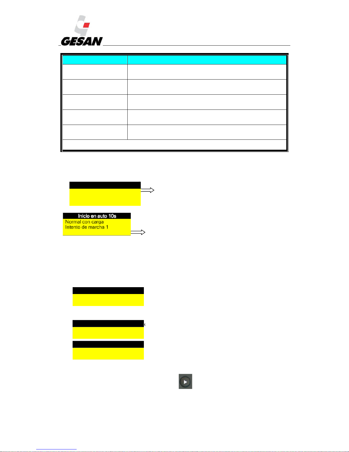
RENTAL & SILENT ENERGY RENTAL GENSETS 4.3
68
INCIDENT DESCRIPTION OF THE ELECTRIC OPENING
ALARM
Electric opening
Generator overcurrent
Generator current above the limit.
ALARM
Electric opening
Auxiliary inputs
The auxiliary inputs can be configured and will show the message
indicated by the user.
ALARM
Electric opening
kW overload
The power (kW) generated is above the limit.
ALARM
Electric opening
Earthing current fault
The earthing current is above the limit (optional).
ALARM
Electric opening
Negative line sequence
Indicates a current imbalance in the generator.
Note: The electric openings are recorded and stop the generator in a controlled manner: first they open the generator breaker
to
eliminate the load and then carry out the sequence to cool and stop the engine.
Typical messages in the information display:
This message indicates that the generator set is ready to
work in the event of a mains failure or a remote start-up
command.
This message indicates that the generator set has received the
start-up command in automatic mode due to a mains failure.
This message is displayed when the generator set is working in
automatic mode. It shows the voltage measured between line and neutral (L-N), the highest current of
the three lines, the nominal frequency, the voltage between lines (L-L) and the total active power
(kW).
Display of measurement parameters:
Engine temperature, in degrees Centigrade (ºC) and in degrees Fahrenheit
(ºF)
Pressure of the engine oil, in Bar, PSI and kPa
Current of each of the lines, in amperes (A)
Events log:
To see the events log repeatedly press the button until it is shown in the display.
This screen records the stoppage alarms that have occurred in the generator, but not the warnings.
The screen shown will be similar to the following:
Onstandby in automatic
Normal with load
Coolingtemperature
60 ºC 140 ºF
Oilpressure
6 Bar 87 PSI
600 kPa
Generator amps
L1 L2 L3
238 241 241
Page 70
RENTAL & SILENT ENERGY RENTAL GENSETS 4.3
69
Events log 1/50
Low oil pressure
Stop
12 Sep 2007, 08:25:46
“On 12 September at 08:25:46, 2007, the module detected that the oil pressure was below the minimum
value and has stopped the generator set. It is the first event of a total of 50 stored.
To pass from one event to another press the button .To exit the main screen press .
Viewing information:
The display order of the screens is the following:
Status screen
Instruments screen (engine, generator set and grid)
Alarms screen
ECU DTCs (only for engines with electronic control)
Events log
Programmer (if enabled)
About
You can move between the different screens by pressing the button . Once you have selected a
screen, the display will stay on it. After a period of inactivity, the display will change to the status screen.
In the instruments screen, the various values will be shown automatically without you having to
press any button. Alternatively, you can move among the various values by pressing or .
These deactivates the autoscroll and if no button is pressed it returns to the status screen. To reinstate the
autoscroll press or until the title of the instruments screen is shown.
If an alarm is activated while the instruments screen is displayed, the display will jump to the alarm
screen automatically.
Page 71

RENTAL & SILENT ENERGY RENTAL GENSETS 4.3
70
The content of the instruments screen is the following:
Engine:
Engine speed
Oil pressure
Cooling temperature
Battery voltage
Hours of operation of the unit
Oil temperature*
Coolant temperature*
Air intake temperature*
Exhaust gas temperature*
Fuel temperature*
Turbo pressure*
Fuel pressure*
Fuel consumption*
Fuel consumed*
Fuel level*
Auxiliary sensors (if any and if configured)
Need for engine maintenance (if configured)
Link with the electronic control unit of the engine*
* When the module is connected to an engine electronic control unit that is correctly configured and compatible.
Generator set:
Voltage L-N
Voltage L-L
Frequency
Currents
Earthing current (optional)
Power (kW)
Active power (kVA)
Power factor:
Reactive power (kVAr)
Energy (kWh, kWAh, kVArh)
Line sequence
Electrical grid (DSE 7320):
Voltage L-N
Voltage L-L
Frequency
About:
Module
Version
USB ID – Identifier for connection to PC via USB
Version of analogue instrumentation
Version of firmware update
Page 72
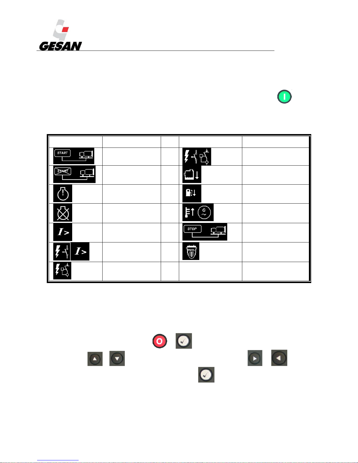
RENTAL & SILENT ENERGY RENTAL GENSETS 4.3
71
If at any moment the instruments screen shows *****, it means that this parameter is not available (the engine does not
provide this parameter).
If at any moment the instruments screen shows ####### with the generator set in OFF/AUTOMATIC mode (with the
engine stopped), it means the module is not connected to the engine at that precise moment. Press button (6) to show
the value.
Alarm or indication LED:
PICTOGRAM DESCRIPTION PICTOGRAM DESCRIPTION
Remote start-up Int. trip. Magnetothermic
switch and differential
Remote shut-off Low water level alarm
Warning alarm Low fuel level alarm
Stoppage alarm High alternator temp.
Overload alarm Remote shutdown
Int. trip.
Magnetothermic switch
Alarm due to water in fuel
separator
Int. trip. Differential
Configuration of the current date and time:
The date and time can be configured. When the battery is disconnected, the time and date values
are still updated. When the battery is reconnected the values will be correct.
The date and time values are used in the events log, so it is important they are correct. To enter
the date and time follow these steps:
Simultaneously press the buttons and . Then enter the PIN number using the push-
buttons or , to select the correct values and use the push-buttons and to
change from one digit to another. To finish, press the button .
Page 73
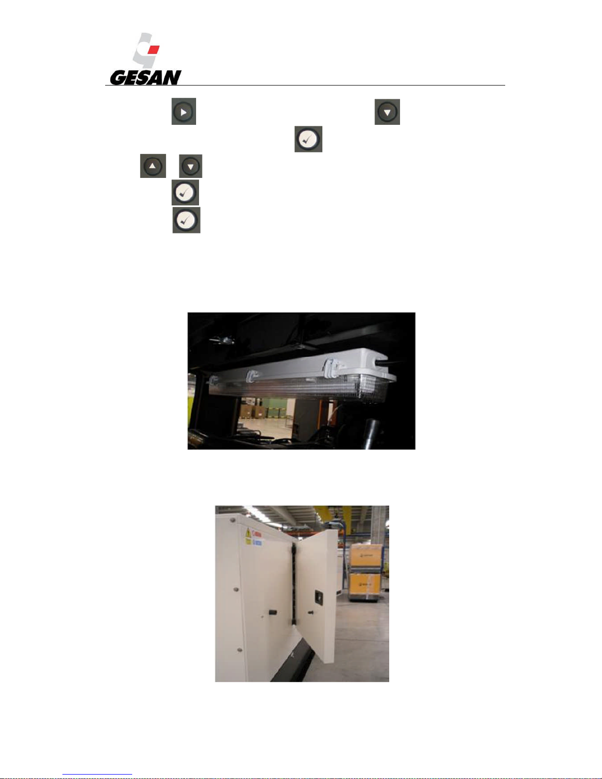
RENTAL & SILENT ENERGY RENTAL GENSETS 4.3
72
Press the button until you reach the instruments screen and then until you reach the
“Date and time” parameter. Then press the button : the digits will start to blink. Press the push-
buttons or to adjust to the desired values.
Press the button to confirm the value entered.
Hold down to exit the editor at any time.
14.5.2. Lightning
The SILENT ENERGY RENTAL series is lit with 12 V or 24 V lamps.
Picture 40: Interior illumination
14.5.3. Silent blocks in doors
Picture 41: Silent blocks in doors
Page 74
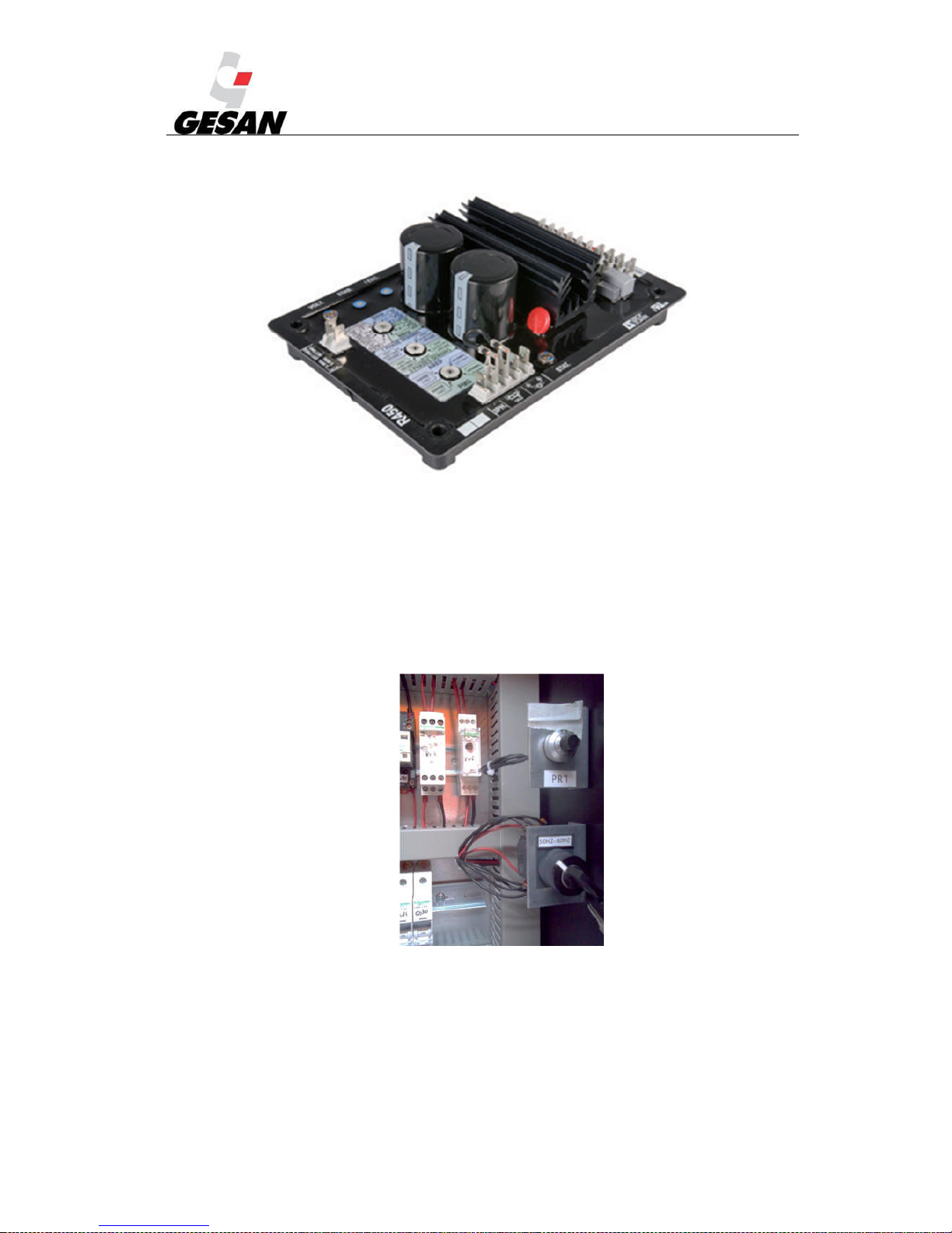
RENTAL & SILENT ENERGY RENTAL GENSETS 4.3
73
14.5.4. AVR in switchboard
Picture 42: AVR in switchboard
a) Adjusting the voltage on gensets with 50/60 Hz selector switch
You must operate as per the following instructions in order to adjust the
voltage.
-When operating at 50 Hz: In order to adjust the voltage it must be done
through the potentiometer (PR1) installed inside the control panel (on the right
side above the frequency selector switch).
Picture 43: Voltage potentiometer and frequency selector switch
-When operating a 60 Hz: In order to adjust the voltage it will be necessary
to adjust it from the AVR. The AVR could be installed either in the control
panel or in the Alternator..
Page 75

RENTAL & SILENT ENERGY RENTAL GENSETS 4.3
74
When adjusting the voltage at 60 Hz, the voltage a 50 Hz will be modified. So
it will be necessary to adjust the voltage when operating 50 Hz, using the
procedure described before “when operating at 50 Hz”.
Certain operating values could be out of range of the operating values controlled by
the control card. In case you believe that you need to modify this parameters please
contact with GESAN.
Page 76

RENTAL & SILENT ENERGY RENTAL GENSETS 4.3
75
15. ANNEX 3: PICTURES INDEX:
Picture 1- Generator set with casing ______________________________________6
Picture 2- Exploded view of RENTAL soundproofed generator set_______________7
Picture 3-Inside a soundproofed generator set ______________________________8
Picture 4-Pictograms for acoustic power and compulsory hearing protection ______8
Picture 5- Generic control panel _________________________________________9
Picture 6 - Control panel on Deep Sea control board All the instruments are optional.
___________________________________________________________________10
Picture 7 - Control panel on InteliGen____________________________________11
Picture 8- On-site trailer ______________________________________________12
Picture 9 Approved speed trailer ________________________________________12
Picture 10- Liquid collection tray________________________________________14
Picture 11- Elevation gantry____________________________________________15
Picture 12- Pump SAB-BE _____________________________________________19
Picture 13- Lateral power cables trapdoor entry____________________________22
Picture 14- Power cables entry by bedplate________________________________22
Picture 15- Deep Sea 7310 control module ________________________________29
Picture 16- INTELIGENNTDigital Control Module__________________________40
Picture 17-Types of oil recommended according to temperature _______________46
Picture 18 -Oil level dipstick. ___________________________________________47
Picture 19- Identification plate__________________________________________54
Picture 20 This genset may start without prior warning ______________________55
Picture 21 General warning ____________________________________________55
Picture 22 Unknown hazard warning_____________________________________55
Picture 23 230 volt electrical hazard _____________________________________55
Picture 24 400 volt electrical hazard _____________________________________55
Picture25 Lifting point ________________________________________________55
Picture26 Possible battery spill _________________________________________55
Picture27Earthing connection __________________________________________55
Picture28 Noise level 90 dB ____________________________________________55
Picture29 Noise level 114 dB ___________________________________________55
Picture30 Mandatory use of hearing protection_____________________________55
Picture31 Coolant drainage____________________________________________55
Picture32 Oil drainage________________________________________________55
Picture33 Fuel drainage_______________________________________________55
Picture 34 Battery isolator _____________________________________________55
Picture 35:High temperature ___________________________________________55
Picture 36-Inside a soundproofed generator set ____________________________56
Picture 37-Switchboard diagram ________________________________________57
Picture 38- Switchboard diagram________________________________________59
Picture 39- Deep Sea 7320 control module ________________________________61
Picture 40: Interior illumination ________________________________________72
Picture 41: Silent blocks in doors________________________________________72
Picture 42: AVR in switchboard_________________________________________73
Picture 43: Voltage potentiometer and frequency selector switch_______________73
Page 77
RENTAL & SILENT ENERGY RENTAL GENSETS 4.3
76
16. ANNEX 4: DERATING OF ENGINE POWER RATING:
Engine power rating is declared for the following conditions in accordance with the norms ISO8528-1:2005 and ISO-3046-1:2002.
- Air pressure: 100 kPa
- Temperature: 25ºC
- Relative humidity: 30%
If site ambient conditions are different from standard, derating of engie power rating is possible.
This derating depends on the characteristics of every engine. Please consult those derating in his
technical sheets.
According to norm ISO-3046-1:2002, the derating of engine power rating could be found are:
16.1.DERATING OF POWER RATING OF TTURBOCHARGED ENGINES WITHOUT
CHARGE AIR COOLING:
Altitude from sea Barometric pressure Temperature (ºC)
m kPa
-10 0 5 10 15 20 25 30 35 40 45 50
0 101,3 1,33 1,23 1,18 1,13 1,09 1,05 1,01 0,97 0,94 0,90 0,87 0,84
100 100,1 1,32 1,22 1,17 1,12 1,08 1,04 1,00 0,96 0,93 0,90 0,86 0,83
200 99,5 1,31 1,21 1,16 1,12 1,08 1,03 1,00 0,96 0,92 0,89 0,86 0,83
300 98,7 1,31 1,20 1,16 1,11 1,07 1,03 0,99 0,95 0,92 0,89 0,85 0,82
400 96,7 1,29 1,18 1,14 1,09 1,05 1,01 0,97 0,94 0,90 0,87 0,84 0,81
500 95,5 1,27 1,17 1,13 1,08 1,04 1,00 0,96 0,93 0,89 0,86 0,83 0,80
600 94,4 1,26 1,16 1,12 1,07 1,03 0,99 0,96 0,92 0,89 0,85 0,82 0,79
700 93,2 1,25 1,15 1,11 1,06 1,02 0,98 0,95 0,91 0,88 0,85 0,82 0,79
800 92,1 1,24 1,14 1,10 1,05 1,01 0,97 0,94 0,90 0,87 0,84 0,81 0,78
900 90,9 1,23 1,13 1,08 1,04 1,00 0,96 0,93 0,89 0,86 0,83 0,80 0,77
1000 89,9 1,22 1,12 1,07 1,03 0,99 0,96 0,92 0,88 0,85 0,82 0,79 0,76
1100 88,8 1,20 1,11 1,06 1,02 0,98 0,95 0,91 0,88 0,84 0,81 0,78 0,76
1200 87,7 1,19 1,10 1,05 1,01 0,97 0,94 0,90 0,87 0,84 0,80 0,78 0,75
1300 86,7 1,18 1,09 1,04 1,00 0,96 0,93 0,89 0,86 0,83 0,80 0,77 0,74
1400 85,6 1,17 1,08 1,03 0,99 0,96 0,92 0,88 0,85 0,82 0,79 0,76 0,73
1500 84,5 1,16 1,07 1,02 0,98 0,95 0,91 0,87 0,84 0,81 0,78 0,75 0,73
1600 83,5 1,15 1,06 1,01 0,97 0,94 0,90 0,87 0,83 0,80 0,77 0,75 0,72
1700 82,4 1,14 1,05 1,00 0,96 0,93 0,89 0,86 0,82 0,79 0,77 0,74 0,71
1800 81,5 1,13 1,04 1,00 0,96 0,92 0,88 0,85 0,82 0,79 0,76 0,73 0,70
1900 80,5 1,12 1,03 0,99 0,95 0,91 0,87 0,84 0,81 0,78 0,75 0,72 0,70
2000 79,5 1,11 1,02 0,98 0,94 0,90 0,87 0,83 0,80 0,77 0,74 0,72 0,69
2200 77,6 1,08 1,00 0,96 0,92 0,88 0,85 0,82 0,79 0,76 0,73 0,70 0,68
2400 75,6 1,06 0,98 0,94 0,90 0,87 0,83 0,80 0,77 0,74 0,71 0,69 0,66
2600 73,7 1,04 0,96 0,92 0,88 0,85 0,81 0,78 0,75 0,73 0,70 0,67 0,65
2800 71,9 1,02 0,94 0,90 0,86 0,83 0,80 0,77 0,74 0,71 0,68 0,66 0,63
3000 70,1 1,00 0,92 0,88 0,85 0,81 0,78 0,75 0,72 0,70 0,67 0,64 0,62
3200 68,4 0,98 0,90 0,87 0,83 0,80 0,77 0,74 0,71 0,68 0,66 0,63 0,61
3400 66,7 0,96 0,88 0,85 0,81 0,78 0,75 0,72 0,69 0,67 0,64 0,62 0,60
3600 64,9 0,94 0,87 0,83 0,80 0,76 0,73 0,71 0,68 0,65 0,63 0,60 0,58
3800 63,2 0,92 0,85 0,81 0,78 0,75 0,72 0,69 0,66 0,64 0,61 0,59 0,57
4000 61,6 0,90 0,83 0,80 0,76 0,73 0,70 0,68 0,65 0,62 0,60 0,58 0,56
Note: Environmental conditions of T=298 K y P=100 kPa.
In order to know the particular engine power rating derating, refer to manufacturer technical
specifications.
Page 78
RENTAL & SILENT ENERGY RENTAL GENSETS 4.3
77
16.2.DERATING OF ENGINE POWER RATING OF TURBOCHARGED ENGINES WITH
CHARGE AIR COOLING:
Altitude from sea Barometric pressure Temperature (ºC)
m kPa -10 0 5 10 15 20 25 30 35 40 45 50
0 101,3 1,28 1,22 1,19 1,16 1,13 1,11 1,08 1,06 1,04 1,01 0,99 0,97
100 100,1 1,27 1,21 1,18 1,15 1,12 1,10 1,07 1,05 1,03 1,00 0,98 0,96
200 99,5 1,26 1,20 1,17 1,14 1,12 1,09 1,07 1,04 1,02 1,00 0,98 0,96
300 98,7 1,25 1,19 1,16 1,14 1,11 1,09 1,06 1,04 1,02 0,99 0,97 0,95
400 96,7 1,23 1,17 1,15 1,12 1,09 1,07 1,04 1,02 1,00 0,98 0,96 0,94
500 95,5 1,22 1,16 1,13 1,11 1,08 1,06 1,03 1,01 0,99 0,97 0,95 0,93
600 94,4 1,21 1,15 1,12 1,10 1,07 1,05 1,02 1,00 0,98 0,96 0,94 0,92
700 93,2 1,20 1,14 1,11 1,09 1,06 1,04 1,01 0,99 0,97 0,95 0,93 0,91
800 92,1 1,19 1,13 1,10 1,08 1,05 1,03 1,01 0,98 0,96 0,94 0,92 0,90
900 90,9 1,18 1,12 1,09 1,07 1,04 1,02 0,99 0,97 0,95 0,93 0,91 0,89
1000 89,9 1,17 1,11 1,08 1,06 1,03 1,01 0,99 0,96 0,94 0,92 0,90 0,88
1100 88,8 1,15 1,10 1,07 1,05 1,02 1,00 0,98 0,96 0,93 0,91 0,89 0,88
1200 87,7 1,14 1,09 1,06 1,04 1,01 0,99 0,97 0,95 0,92 0,90 0,89 0,87
1300 86,7 1,13 1,08 1,05 1,03 1,00 0,98 0,96 0,94 0,92 0,90 0,88 0,86
1400 85,6 1,12 1,07 1,04 1,02 0,99 0,97 0,95 0,93 0,91 0,89 0,87 0,85
1500 84,5 1,11 1,06 1,03 1,01 0,98 0,96 0,94 0,92 0,90 0,88 0,86 0,84
1600 83,5 1,10 1,05 1,02 1,00 0,97 0,95 0,93 0,91 0,89 0,87 0,85 0,83
1700 82,4 1,09 1,04 1,01 0,99 0,96 0,94 0,92 0,90 0,88 0,86 0,84 0,82
1800 81,5 1,08 1,03 1,00 0,98 0,96 0,93 0,91 0,89 0,87 0,85 0,83 0,82
1900 80,5 1,07 1,02 0,99 0,97 0,95 0,92 0,90 0,88 0,86 0,84 0,83 0,81
2000 79,5 1,06 1,01 0,98 0,96 0,94 0,92 0,89 0,87 0,86 0,84 0,82 0,80
2200 77,6 1,04 0,99 0,96 0,94 0,92 0,90 0,88 0,86 0,84 0,82 0,80 0,79
2400 75,6 1,02 0,97 0,95 0,92 0,90 0,88 0,86 0,84 0,82 0,80 0,79 0,77
2600 73,7 1,00 0,95 0,93 0,90 0,88 0,86 0,84 0,82 0,80 0,79 0,77 0,75
2800 71,9 0,98 0,93 0,91 0,89 0,87 0,85 0,83 0,81 0,79 0,77 0,75 0,74
3000 70,1 0,96 0,91 0,89 0,87 0,85 0,83 0,81 0,79 0,77 0,76 0,74 0,72
3200 68,4 0,94 0,89 0,87 0,85 0,83 0,81 0,79 0,77 0,76 0,74 0,72 0,71
3400 66,7 0,92 0,88 0,86 0,83 0,81 0,80 0,78 0,76 0,74 0,73 0,71 0,69
3600 64,9 0,90 0,86 0,84 0,82 0,80 0,78 0,76 0,74 0,73 0,71 0,69 0,68
3800 63,2 0,88 0,84 0,82 0,80 0,78 0,76 0,74 0,73 0,71 0,69 0,68 0,66
4000 61,6 0,87 0,82 0,80 0,78 0,76 0,75 0,73 0,71 0,70 0,68 0,66 0,65
Note: Environmental conditions of T=298 K y P=100 kPa.
Intercooler reference conditions: T=330 K, Tc=300 K y P=70 kPa.
In order to know the particular engine power rating derating, refer to manufacturer technical
specifications.
Page 79
RENTAL & SILENT ENERGY RENTAL GENSETS 4.3
78
16.3.DERATING OF ENGINE POWER RATING OF NATURALY ASPIRED ENGINES:
Altitude from sea Barometric pressure
Humidity: 30%
Temperature (ºC)
-10 0 5 10 15 20 25 30 35 40 45
0 101,30 1,14 1,10 1,09 1,07 1,05 1,03 1,02 1,00 0,98 0,97 0,95
100 100,00 1,12 1,09 1,07 1,05 1,03 1,02 1,00 0,98 0,97 0,95 0,93
200 98,90 1,11 1,07 1,05 1,04 1,02 1,00 0,99 0,97 0,95 0,94 0,92
400 96,70 1,08 1,04 1,03 1,01 0,99 0,98 0,96 0,94 0,93 0,91 0,90
600 94,40 1,05 1,01 1,00 0,98 0,96 0,95 0,93 0,92 0,90 0,88 0,87
800 92,10 1,02 0,98 0,97 0,95 0,93 0,92 0,90 0,89 0,87 0,86 0,84
1000 89,90 0,99 0,95 0,94 0,92 0,91 0,89 0,88 0,86 0,85 0,83 0,82
1200 87,70 0,96 0,92 0,91 0,89 0,88 0,86 0,85 0,83 0,82 0,80 0,79
1400 85,60 0,93 0,90 0,88 0,87 0,85 0,84 0,82 0,81 0,79 0,78 0,76
1600 83,50 0,90 0,87 0,85 0,84 0,82 0,81 0,80 0,78 0,77 0,75 0,74
1800 81,50 0,87 0,84 0,83 0,81 0,80 0,79 0,77 0,76 0,74 0,73 0,72
2000 79,50 0,85 0,82 0,80 0,79 0,77 0,76 0,75 0,73 0,72 0,71 0,69
2200 77,60 0,82 0,79 0,78 0,76 0,75 0,74 0,72 0,71 0,70 0,68 0,67
2400 75,60 0,79 0,76 0,75 0,74 0,72 0,71 0,70 0,69 0,67 0,66 0,65
2600 73,70 0,77 0,74 0,73 0,71 0,70 0,69 0,67 0,66 0,65 0,64 0,62
2800 71,90 0,74 0,72 0,70 0,69 0,68 0,66 0,65 0,64 0,63 0,62 0,60
3000 70,10 0,72 0,69 0,68 0,67 0,65 0,64 0,63 0,62 0,61 0,59 0,58
3200 68,40 0,70 0,67 0,66 0,64 0,63 0,62 0,61 0,60 0,59 0,57 0,56
3400 66,70 0,67 0,65 0,63 0,62 0,61 0,60 0,59 0,58 0,57 0,55 0,54
3600 64,90 0,65 0,62 0,61 0,60 0,59 0,58 0,57 0,55 0,54 0,53 0,52
3800 63,20 0,62 0,60 0,59 0,58 0,57 0,56 0,55 0,53 0,52 0,51 0,50
4000 61,50 0,60 0,58 0,57 0,56 0,55 0,53 0,52 0,51 0,50 0,49 0,48
Note: Environmental conditions of T=298 K y P=100 kPa. Relative humidity 30%
In order to know the particular engine power rating derating, refer to manufacturer technical
specifications.
Page 80
*RUPOS ELECTRÓGENOS EUROPA, S.A.
3ROtJRQR,QGXVWULDO3LWDUFR,,QDYH
7HOpIRQR)D[
08(/=DUDJR]D63$,1
ZZZJHVDQFRPH[SRUW#JHVDQFRPLQIR#JHVDQFRP
V4.4
 Loading...