

Page 1

Standalone HVAC Room Energy Sensor
G
GG
GESA
ESAESA
ESA
General
The GH-800 is specially developed to provide intelligent HVAC energy management
of vacant rooms of lodging industry. With this system installed, hotelier can effectively
reduce the energy expense from HVAC operation. The system utilizes reliable
sensing technology and sophisticated logic control software to verify the occupancy
status of guestroom. When guestroom is physically occupied, the system will allow
the occupant to operate HVAC according to personal requirement. After the room is
vacant, the system will automatically shut off the unnecessary HVAC operation to
reduce energy consumption and equipment wear. To ensure optimum performance
of the system, please carefully read this instruction before installing.
Applications
Benefits
• Resort/Hotel/Motel Guestrooms
• School/College Dormitories
• Timeshare Vacation Units
• Military Lodging Facility
• Commercial Offices
• Conference Rooms
• Reduce building energy consumption
• Reduce equipment operation load
• Prolong operation life of equipment
• Reduce building management cost
• Enjoy comfort of automatic control
Features
• Smart Guestroom Occupancy Verification
• Superior RFI/EMI immunity
• High density pyroelectric infrared detection zones
• Fail-safe system operation protection ensure HVAC operation even system failure
• HVAC start cycle delay enabled
• Programmable temperature high-low setbacks for unoccupied mode
• Occupancy status signal output
• Audible & visible test indication
• 24V/dry contact selectable output
• Corner/Wall mount available
• Multi-directional adjustment
• Optional HVAC slave sensor connectivity
Page 2
Standalone HVAC Room Energy Sensor
G
GG
GESA
ESAESA
ESA
Specification
Master Sensor
Model GH-MS1
Infrared sensor & Detection Pattern 110° Dual element
Power supply 24 ± 2 VAC/DC
Current drain Standby: 20 mA, Operating: 10 mA
Relay output Form C (NC-COM-NO), 24V or dry contact selectable
Max. switching current NO: 5A, NC: 3A, resistive load
Max. switching voltage AC: 250V, DC: 30 V
High / Low temperature setback High - 26/28/30°C (79/82/85°F) , Low - 11/13/15°C (51/55/59°F) - via jumper setting
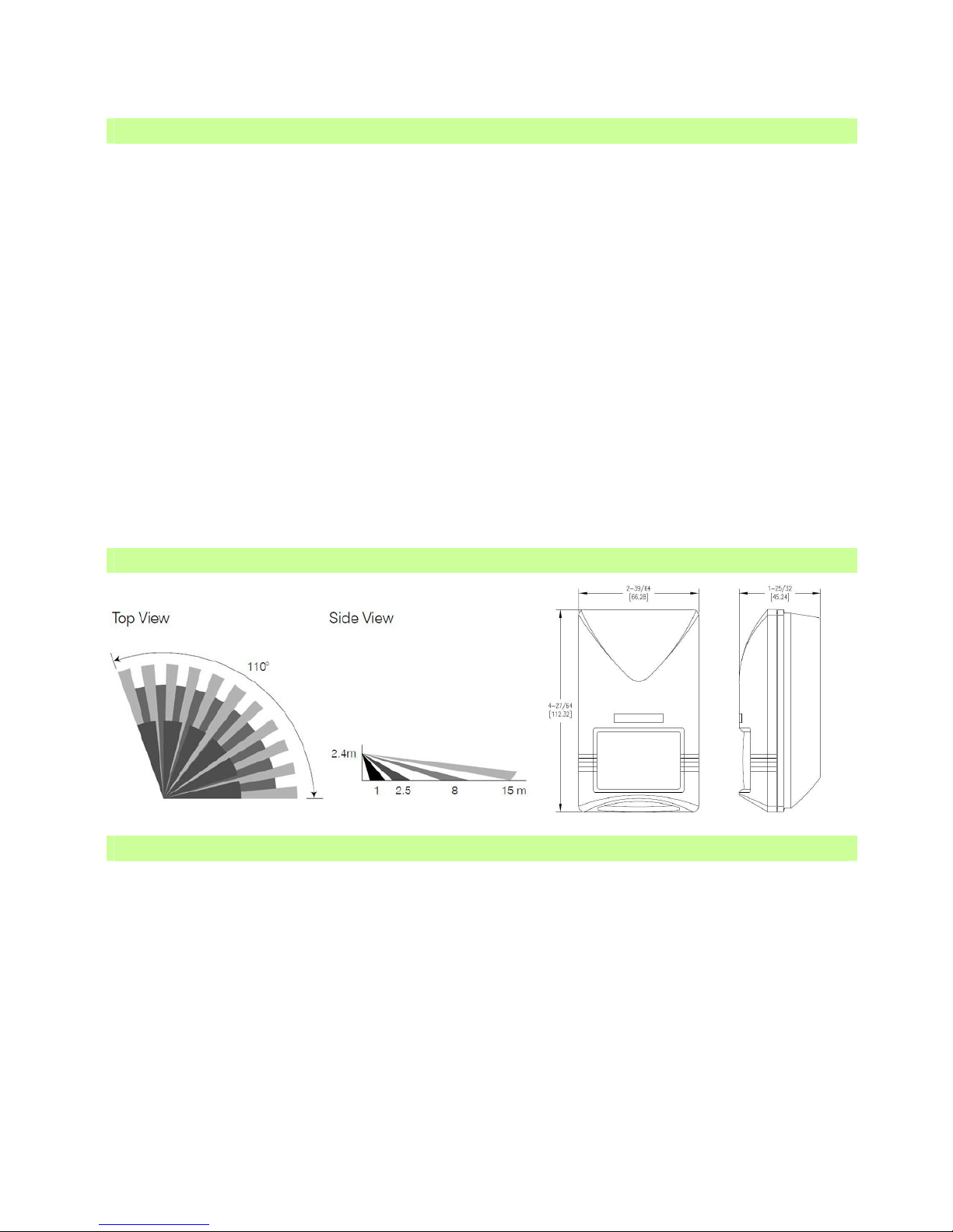
Detection Pattern 110°wide, 15m (50ft) long @25°C(77°F)
Warm-up period 25 ± 2 seconds
Restart cycle protection 2 minutes, can be disabled
Test indication Buzzer (audible) and LED (visible) , can be disabled
Housing material ABS
Protection class IP 31
Operating temperature -10°C ~ 60°C (14°F ~ 140°F)
Mounting height 1.8 – 3.6m
RFI immunity Av. 20V/m (10 – 1,000 MHz)
Detectable speed 0.1 – 3.0 m/sec
Operating humidity Max. 95% RH non-condensated
Dimension 112 x 66 x 45 mm (4.4 x 2.6 x 1.8 inch)
Power Pack
Model PP-1
Power supply 90 ~ 277 VAC
Power output 24 VDC, 200 mA max.
HVAC Relay output Normally Closed (fail-safe)
Max. switching current 10A, resistive load
Max. switching voltage 250V
Housing material ABS, flame-proof
Operating temperature -10°C ~ 60°C (14°F ~ 140°F)
Operating humidity Max. 95% RH non-condensated
Dimension 110 x 52.5 x 30 mm (4.3 x 2.1 x 1.2 inch)
System Component in GH-800
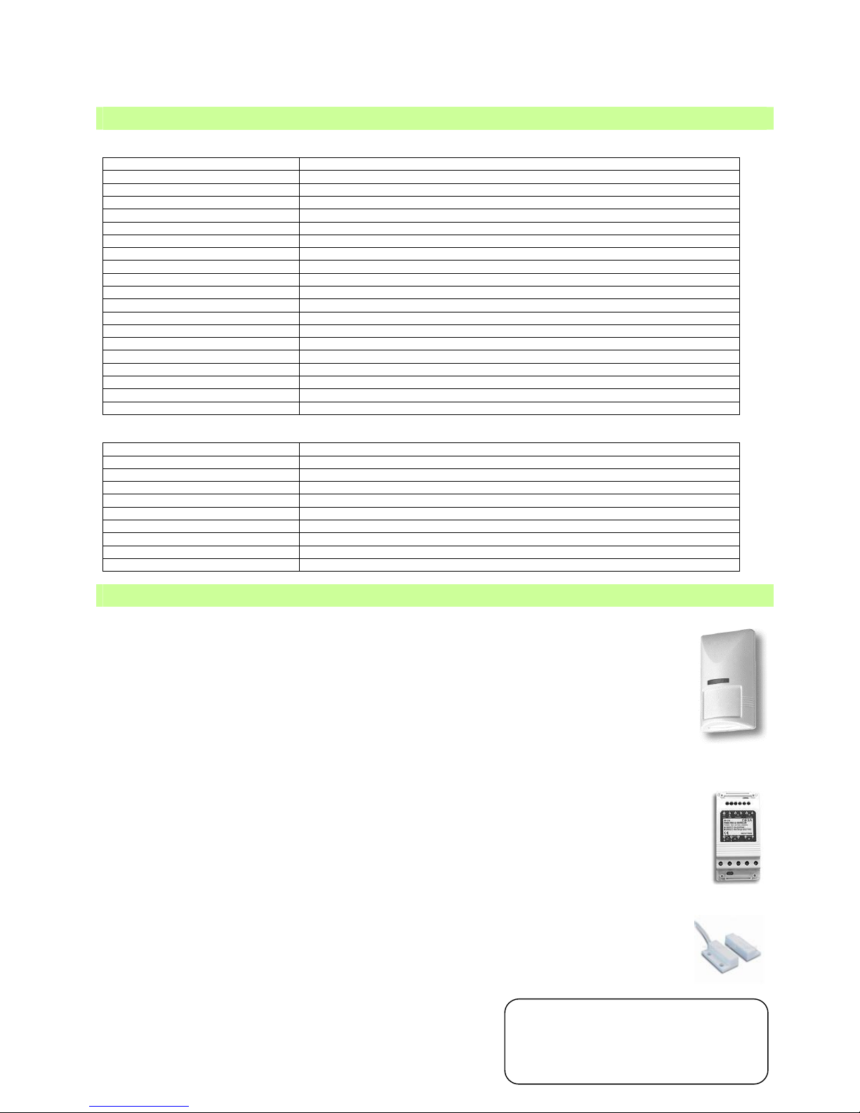
GH-MS1 Master Sensor
GH-MS1 is the master sensor of Standalone HVAC Room Energy Sensor. It consists of a high
sensitivity passive infrared (PIR) motion sensor and sophisticated microprocessor with
intelligent logic control in an aesthetically pleasing housing. It should be mounted on the wall
(corner mount recommended) to detect the presence of human by sensing the movement of
body heat energy. In addition to the guest presence detection and verification, the GH-MS-1
also provides various operation settings and component connections of the system. To avoid
the room becoming too hot or too cold during unoccupied period, thus requires excessive time
and energy to cool down or warm up, the GH-MS1 also features a programmable secondary
thermostat (via jumper) with various high and low temperature limit settings. The HVAC will be
activated if room temperature exceeds the set range.
PP-1 Power Pack
This power pack not only provides 24 VDC power supply for GH-MS1, but also controls the
operation of HVAC unit. The GH-MS1 has a fail-safe design. In case that GH-MS1 Master
Sensor is malfunction, the HVAC unit can still be operated manually as without using the GHMS1 master sensor.
GH-MC Door Sensor
The GH-MC Door sensor is a pair of magnetic contact to verify open/closed status. It should be
wired to the corresponding terminals of GH-MS1 to report the open/closed status of the door.
Once the door is opened, the GH-MS1 will enter into “standby” mode to detect the guest
presence. If motion is detected, the GH-MS1 will verify the room as “occupied” status and allow
guest to operate the thermostat and set the temperature of HVAC unit by themselves. If no
motion is detected within a period of time, then GH-MS1 will verify the room “vacant” and then
shut off the HVAC operation. Note: The GH-MS1 will automatically shut off the HVAC operation
if any sensor connected door or window is left open for more than 5 minutes.
ALTON CONTROLS SDN. BHD.
www.alton.com.my
Page 3
Standalone HVAC Room Energy Sensor
G
GG
GESA
ESAESA
ESA
Termination Diagram
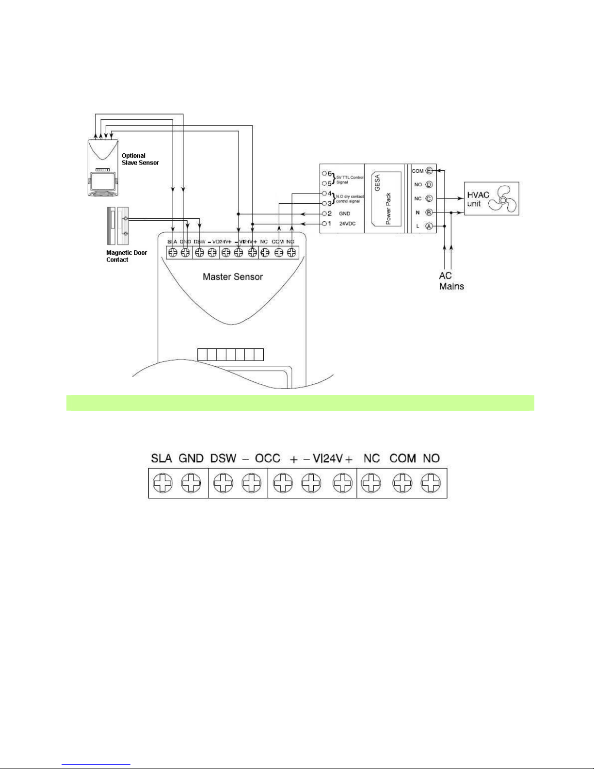
To connect the wires between GH-MS1 and other components of the system, the terminals of GH-MS1 should be connected with correct
wire to ensure optimum performance. Each terminal block of GH-MS1 are described as follow in the left to right sequence.
SLA
This terminal and terminal “GND” are for connection with the N.O. output of slave sensor. If multiple slave sensors are used,
the connection should be made in parallel.
GND
This ground terminal normally pairs with SLA or DSW for connection of slave sensor or door switch.
DSW
This terminal and terminal “GND” are for connection with the door switch. If multiple door/window switches are used, the
connection should be made in series.
-OCC+
These two terminals provide occupancy status output for guest-in-room detection.
-24V+
These two terminals are for the input of 24V power supply from power pack.
NC
This terminal and terminal “COM” form the Normally Closed (NC) output of GH-MS1.
COM
Common pole of relay output.
NO
“NO” and terminal “COM” form Normally Open (NO) output of GH-MS1.
Page 4
Standalone HVAC Room Energy Sensor
G
GG
GESA
ESAESA
ESA
Wiring Technique
CAUTION
• HVAC units may contain AC mains power. To prevent electric shock, ensure that AC mains is OFF before
connecting with HVAC units.
• Do NOT take shortcuts when connecting the HVAC power circuits.
Wiring Techniques
Conceal the sensor wiring by “fishing” the wire from hollow wall or partition.
Drill an adequate hole behind the sensor, so that the sensor can cover the hole.
Drop a string with a small weight inside the wall to bottom.
Drill another hole on wall at the carpet level. Use a stiff wire with a hook to pull the string out from the hole.
Pull the cable to the door switch, HVAC unit and slave sensor, if necessary
Use proper tool to tuck the wire under the edge of carpet.
Alternatively, staple the wire in the corner and cover it with vinyl corner molding to match room decor.
Wiring should be completed and concealed in a manner that it will not be damaged by hotel guest or housekeeper.
Mount the Sensor (GH-MS1)
1. Remove the sensor cover by releasing the locking screw at the bottom of the housing.
2. Carefully remove the circuit board by releasing the fixing screw.
3. For corner mount (recommended), use the mounting holes on both 45° slopes to mount the base.
4. Lead the cable into the base. Replace the circuit board on the base and fixed with screw.
Coverage Pattern and Dimension
Mounting Guide
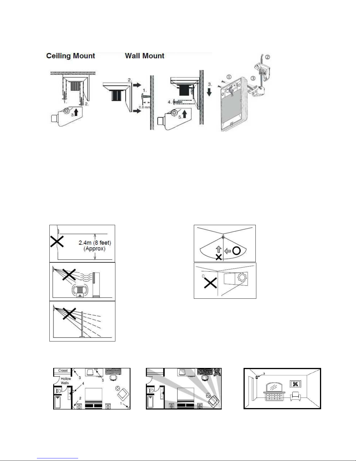
Mount the sensor without bracket
1. Open the front cover by loosening the locking
screw.
2. Remove the PCB from the bottom case with
care.
3. Mount the bottom case on the wall with proper
knockout holes.
4. Lead the cable into the case and replace the PCB
for wiring connection
Mount the sensor with bracket
1. Mount the base of mounting bracket on the
selected position as shown.
2. Lead the cable through the central tunnel of
mounting bracket.
3. Open the front cover by loosening the
locking bolt. Lead the cable into the case and
fix the mounting
bracket with the bottom case of sensor.
4. Connect the cable to the corresponding
terminals.
Page 5
Standalone HVAC Room Energy Sensor
G
GG
GESA
ESAESA
ESA
Mount the Door Switch
1. Select a proper position on the door frame. Drill a3/4” hole on the frame for switch recess. Use the spacer
as a guide, drill two 1/8” holes for fixing.
2. Lead the wires and connect to the terminal block of switch. Insert the switch and fix with pop rivets or screws.
Select Mounting Location of GH-MS1 Master Sensor
Selection a proper mounting location of the GH-MS1 is very important in assuring optimum performance of the
system. Improper location of GH-MS1 may result in poorer performance. Following hints should be fully noticed
before installation.
Reflective materials (mirrors, shiny metal sheets, marble, tiles etc) could reflect the infrared energy emission.
The sensor should be mounted at
8 ft. above the floor, preferably
in a corner that has a good field
of view to the movements of hotel
guest.
The sensor is more
sensitive to the
movements across the
detection zones than
those toward or away
the sensor.
AVOID facing the sensor toward
any object likely to change
temperature rapidly, such as
electric heater or fireplace.
AVOID mounting the
sensor where it will
receive direct sunlight
or
direct draft of
heating/cooling vents.
AVOID locating the sensor where
its detection zones may be
blocked by doors, draperies or
curtains.
Recommended sensor locations
The numbers indicated represent order of preference.
Recommended Mounting Locations in order Preference
Page 6
Standalone HVAC Room Energy Sensor
G
GG
GESA
ESAESA
ESA
Jumper Setting
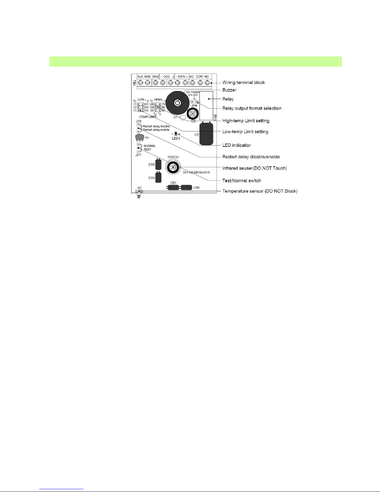
1. Low temperature limit
This jumper allows the selection of 3 different low temperature limits in which the GH-MS1 master sensor will
automatically operate the HVAC when room temperature is lower than the set value. The sensor detects the room
temperature once every 5 minutes. To disable the low temperature limit, remove the jumper. This function will only
operate when room is unoccupied.
2. High temperature limit
This jumper allows the selection of 3 different temperature limits in which the GH-MS1 master sensor will
automatically operate the HVAC when room temperature is higher than the set value. The sensor detects the room
temperature once every 5 minutes. To disable the high temperature limit, remove the jumper. This function will only
operate when room is unoccupied.
3. Relay output format
This jumper allows the selection of relay output format. Place the jumper on both pins will make the relay contact
with 24V power. If dry contact (no load) output is required, remove the jumper off the pins (disconnect the pins).
4. Restart delay enable/disable
This jumper allows to enable/disable the 2-minute short start cycle protection. With this restart delay enabled, the
HVAC will start operating after 2 minutes. This restart delay is generally required by the individual Packaged
Terminal Air Conditioner (PTAC) unit to protect the compressor damaging from frequent activations. To disable
short start protection, place the jumper at disable position.
5. Test/normal
This jumper allows to enable/disable the LED and buzzer indication. When jumper is placed at “TEST” position, the
LED will light for approximately 2 seconds whenever the motion is detected and the buzzer will beep. If jumper is
placed at “NORMAL” position, the LED will NOT light when sensor detects the motion. But it will blink about 10
seconds after the GH-MS1 activate the HVAC. This indication will help the maintenance staff to check if the GHMS1 system is working normal.
GH-MS1 Master Sensor Description
Page 7

Standalone HVAC Room Energy Sensor
G
GG
GESA
ESAESA
ESA
1. After wiring connection is completed, ensure the jumper JP7 is placed at “TEST” mode. Replace and fasten the
front cover with the locking screw.
W henever power is applied on the GH-MS1, please wait for about 25 seconds for sensor to warm-up. During
warm-up period, the buzzer will sound beep-beep (each beep lasts 1 second). Both LED and relay will be activated.
The activated GH-MS1 means the HVAC unit will NOT operate due to its fail-safe design.
2. When warm-up period expires, the buzzer stops sounding, LED lights off, but relay will still be active.
3. DOOR SENSOR TEST - Open the door, the buzzer should sound constantly until the door is closed.
If the buzzer does not sound while door is opened, check the door switch and ensure correct wiring connection
between door switch and GH-MS1.
4. SLAVE SENSOR TEST - If NO slave sensor is installed, please skip this test. The detection of slave sensor
should be tested after the door switch function is tested okay. Walk across in the room of slave sensor installed,
the LED of slave sensor will light on whenever it detects the movement. The buzzer of GH-MS1 will sound one
long beep (1 sec.) and - one short beep (0.2 sec.) when slave sensor is activated.
If the buzzer does not sound when slave sensor detects the movement but the LED of slave sensor is working,
check the wiring between slave sensor and GH-MS1.
5. MASTER SENSOR TEST – W alk across in the room of master sensor installed. The LED will light on and the
buzzer will sound beep-beep (0.2 sec.) whenever master sensor detects the movement. The HVAC unit will
operate at least 30 seconds for every detection.
If no further movement is detected within 30 seconds after the last detection, the HVAC unit will stop operating.
After the system operation test completed, ensure to place the jumper JP7 to “NORMAL” position for normal
operation of the system. The normal operation of GH-800 is quite sophisticated. Many different operation modes
and statuses are carefully managed and controlled by the microprocessor. Various modes and statuses are
described as follow:-
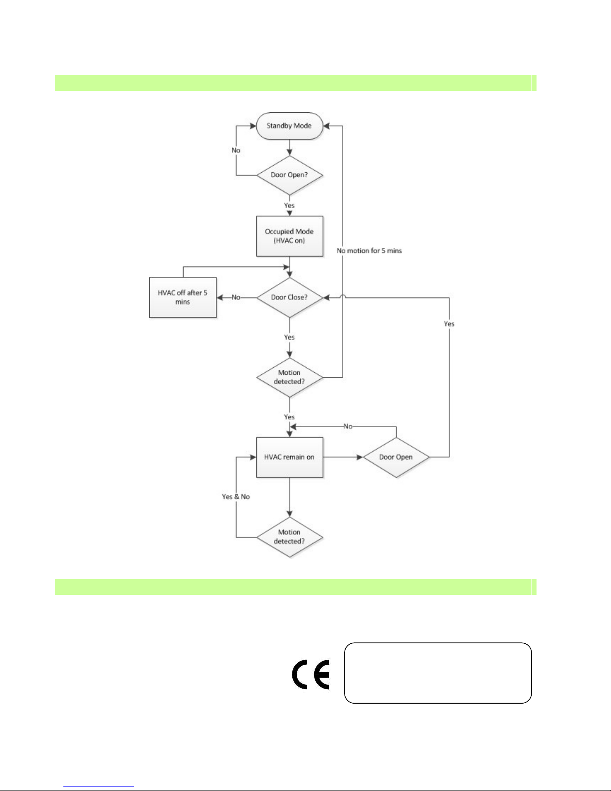
Standby Mode
If the room is vacant, the system will enter into “standby” mode after the warm-up time expires. Under standby
mode, the HVAC unit will not operate.
Temp-control Status
While room is unoccupied, the temperature sensor of GH-MS1 will measure the room temperature every 5 minutes.
When room temperature goes higher or lower than the high/low setting, the HVAC unit will automatically operate
until the room temperature goes back to the set range. Once the room temperature returns to the set range, the
system will return to “standby” mode. This function will only operate if jumper heads are set in place and HVAC unit
is “ON”.
Occupied Mode
If master or any slave sensor detects the movement during standby mode, the system will enter into “occupied”
mode. Under the “occupied” mode, the hotel guests can manage or set the room temperature via the HVAC wall
unit according to their preference.
Door-open Status
Whenever the door is opened, the system will detect it and enter into “door-open” status. The HVAC unit will
operate and LED will flash for 10 seconds. The LED flash is to indicate that the system function is normal. If the
door is left open for more than 5 minutes, the system will shut off the HVAC unit until the door is closed.
Delay Status
Once the door is closed, the system will enter into “delay” status. During this 10-second period, the system will
remain as its original mode.
Waiting Mode
The system will enter into “Waiting” mode after the second delay status expires. If master or any slave sensor
detects the movement during waiting mode, the system will enter into “occupied” mode. If no movement is detected
within 5 minutes, then system will enter into “standby” mode.
System Testing
System Operation
Page 8
Standalone HVAC Room Energy Sensor
G
GG
GESA
ESAESA
ESA
After final installation of the unit, no routine maintenance is required. The GH-800 is not field serviceable and should
be returned if repair is needed (field repair should not be attempted and may void warranty). Be sure to include a brief
description of the problem plus any relevant application notes.
System Flow Chart
Maintenance
ALTON CONTROLS SDN. BHD.
www.alton.com.my
 Loading...