

Page 1
Des igned i n Grand Ra pids MI , USA Ass emble d in Chin a
Car Rear View Mirror Monitor with
7.3 Inch Wide LCD Display Screen
User manual
FK-073A
ECER10
Approval No.: 10R-03 12762
ECER46
Approval No.: 46R-04 0019
Page 2
Welcome to use our Car Rear view mirror monitor with 7.3 inch wide LCD display
screen.
●We reserve the final explanation right on this User's Manual.
●Specifications are subject to change without notice. Sorry for any inconvenience
caused!
●Please make a copy of the important data. We assume no responsibility for the
data loss.
●This manual has been carefully checked. Please contact our service center when
any typing mistake is found.
●Please read the operating instruction carefully and use the accessories only
provided by the original factory to avoid any unexpected damage. No warranty
will be executed if you are not following the instruction or connecting with the
incompatible accessories, we assume no responsibility for any loss and damage
caused hereby.
●Any discrepancy between the pictures with real products hereinafter, the real
one prevails.
●The working voltage of this model is 10V to 30V, and it can be installed in the
truck if its voltage is 24V. Please refer to the camera manual for the camera power
supply, since it's not from the car rear view mirror. The 24V camera is advisable if
installed to truck or purchase the power adapter to convert the voltage.
User's Manual
Chapter one: Product Introduction . . . . . . . . . . . . . . . . . . . . . . . . . . . . . . . . . . . 1
1.1 Package. . . . . . . . . . . . . . . . . . . . . . . . . . . . . . . . . . . . . . . . . . . . . . . . 1
1.2 Features . . . . . . . . . . . . . . . . . . . . . . . . . . . . . . . . . . . . . . . . . . . . . . . 1
1.3 Specification . . . . . . . . . . . . . . . . . . . . . . . . . . . . . . . . . . . . . . . . . . . . 1
1.4 Operating panel . . . . . . . . . . . . . . . . . . . . . . . . . . . . . . . . . . . . . . . . . 2
Chapter two: Installation and Wiring . . . . . . . . . . . . . . . . . . . . . . . . . . . . . . . . . 4
2.1 How to install . . . . . . . . . . . . . . . . . . . . . . . . . . . . . . . . . . . . . . . . . . . 4
2.2 Special bracket . . . . . . . . . . . . . . . . . . . . . . . . . . . . . . . . . . . . . . . . . . 5
2.3 How to wire . . . . . . . . . . . . . . . . . . . . . . . . . . . . . . . . . . . . . . . . . . . . 6
2.4 How to display the rear view mirror screen. . . . . . . . . . . . . . . . . . . . 8
Chapter three: Adjustable Guideline. . . . . . . . . . . . . . . . . . . . . . . . . . . . . . . . . . 9
3.1 About guide line . . . . . . . . . . . . . . . . . . . . . . . . . . . . . . . . . . . . . . . . 10
3.2 What is the regular guide line . . . . . . . . . . . . . . . . . . . . . . . . . . . . . 10
3.3 How to adjust the guide line . . . . . . . . . . . . . . . . . . . . . . . . . . . . . . 11
Chapter f : . . . . . . . . . . . . . . . . . . . . . . . . . . . . . . . . . . . . . . . .our 11Menu Setting
4.1 Remote control. . . . . . . . . . . . . . . . . . . . . . . . . . . . . . . . . . . . . . . . . 12
4.2 Menu setting guidance . . . . . . . . . . . . . . . . . . . . . . . . . . . . . . . . . . . 12
Page 3
Chapter one: Product Introduction
1.3 Specification
The packing box contains the following accessories, please confirm:
Car rear view mirror monitor with 7.3 inch wide LCD display screen
wire harness
User's manual
wire cover
Remote control
For the items listed above, please check with your package box. If any damage,
Please contact with the distributor or the agent as soon as possible.
1.1 Package
●
●
●
●
●
7.3 inch wide LCD display screens
3-way video input
Back up camera display
Automatic brightness adjustment
4.0 mm glass and 21 mm car factory OEM bracket
Adjustable guide line
Mode switch between wide screen and dual screens LCD display separately
1.2 Features
●
●
●
●
φ
●
●
Screen size: 7.3 inch
Display screen: TFT-LCD
Aspect resolution: 1280(H)*390(V)
Working voltage: 12V
Working temperature: -20℃~+65℃
Signal system: PAL/Auto/NSTC
●
●
●
●
●
●
●
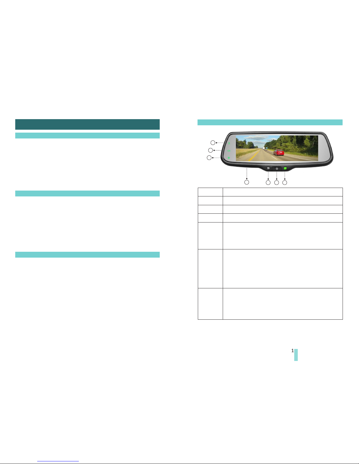
1.4 Operating panel
7.3 inch ultra high brightness display screen
1
Turn on/off the display screen
Indicator
1
2
3
4
5
6
7
2 3 4
7
6
5
Front light sensor
Shortcut key to back up camera
Short press any key in the left until the indicator light is on.
Short press “R” to Back Up Camera. But it doesn't work when
it's in reversing mode.
Switch between different video channels
Short press it to make the video channels switch among
DOUBLE, VIDEO1, VIDEO2, BACK UP CAMERA. No guide line
display on the monitor no matter how many times when you
press “CH”. When the reversing line is connected to the 12V, it
would change to BACK UP CAMERA automatically, and guide line
is on the monitor, which can be adjusted by the remote.
Color mode adjustment
Short press it can adjust the color mode of the image. Four
modes are available, that is STANDARD, BRIGHT, BEAUTIFUL,
and SOFT. Please be noted that these modes only are accessible
when it's not in reversing mode.
Page 4
2 3
8
9
10
11
12
14
15
13
16
17
18
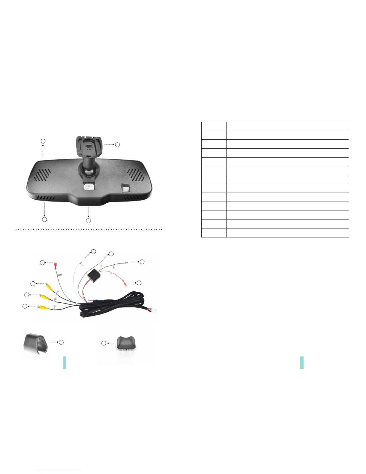
Horn
Special bracket
8
9
10
11
12
13
14
15
16
17
18
19
Red to ACC+
Black to GND
Turn left signal (option)
Turn right signal (option)
Back up signal
Video input
Video input
Camera
Connector
20
Connector cover
19
8
20
Cable cover
Page 5
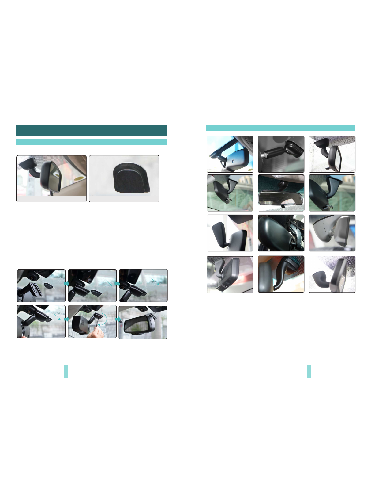
2.1 How to install
Remove the original rear view mirror and remain
the metal base on the windscreen
Original car rear view mirror
Along this direction
to install rear view mirror
Along this direction
to install rear view mirror
Along this direction
to install rear view mirror
contrarotate the fixed
rear view mirror
1
We have many kinds of brackets. one of them must suit for your car, and we are
not going to go through anymore examples, because the space is limited.
If you don’t find the same bracket here as your car, please contact us.
2.2 Special bracket
4 5
Chapter two: Installation and Wiring
Different cars have different brackets. It depends on your vehicle maker and
manufacturer.
There are many methods to remove the original rear view mirror, however, please
don’t force the mirror off the bracket.
The manufacturer will not be responsible for any damage caused to your car by
wrong installation of the mirror.
Remove th e original mirror
Insta ll mirror monitor on the base
Page 6
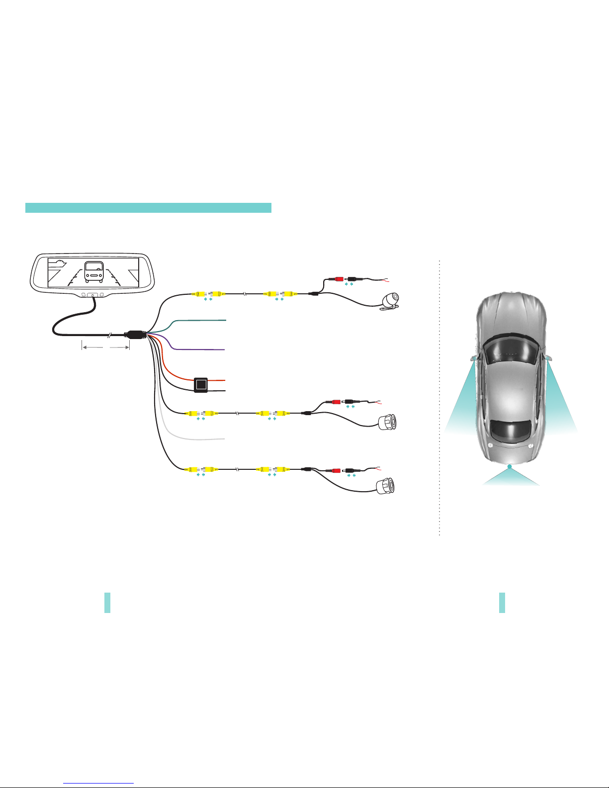
2.3 How to wire
3M
6 7
power harness
PUSE
BOX
Black to GND
Red to A CC +12V
Black to GND
Red to ACC +12V
Black to GND
Red to ACC +12V
Black to GND
Red to ACC +12V
Back up v id eo
Lef t vi deo
Rig ht v ideo
Turn r ight sig nal(o ption )
The advisable installation
position for camera
B
ack u
p v
ide
o
R
i
ght v
i
de
o
By connecting the green line, the reversing signal is input to the rear view mirror
and reversing video can automatically display on the wide 7.3 inch LCD monitor.
Turn l eft sign al (opt ion)
L
ef
t v
i
de
o
CTR 1(Gre en)
it' s advis able to c onnec t the reve rsing l ine
Page 7
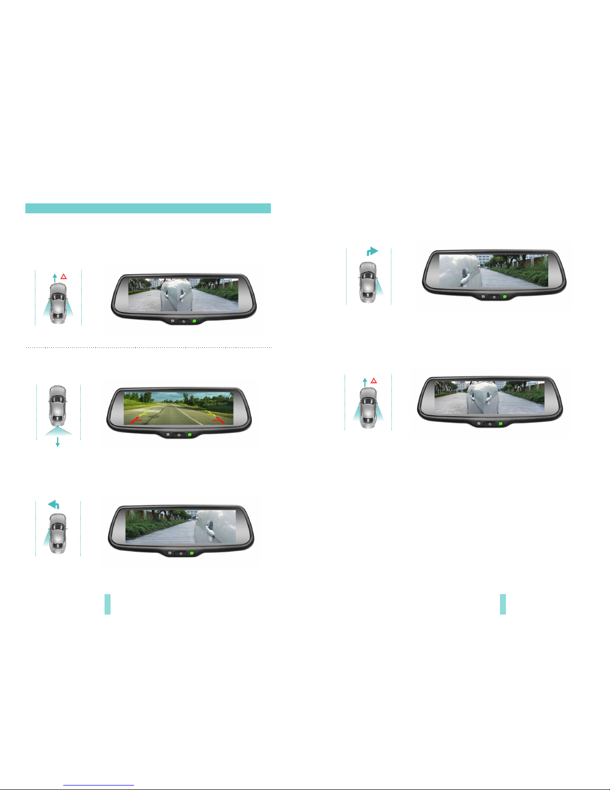
2.4 How to display the rear view mirror screen.
8
Sta tus B:Wid e sc ree n wo uld displ ay the re ar image wh en it's in pa rk ing mode.
Sta tus A: In no rmal dri vi ng , the car mo nitor can disp lay left and righ t v ideo,
to fac ilita te drive rs to ob serve the condi ti on of the t wo si des ( There will be
differ ent vide o dis played on mirror ac cordi ng to the diffe rent loc ation of
cam era ).
Sta tus C : When the car is turn in g to left, the lef t ligh t is on , and (op ti on)
turni ng lef t sign al would trigger autom atica ll y the left camera to get th e fu ll
screen. Afte r it closes for 3S, th e sc reen wo uld get b ac k.
Sta tus D (o ption ): Wh en th e car is turning to right , t he ri ght ligh t i s o n, an d
turni ng right s ignal would trigger automat ically the r ig ht ca mera to get t he
full sc reen. A fter it clo se s for 3 S, t he scre en would ge t back.
Sta tus E (o ption): Whe n th e front two turni ng l ig hts are on, the signa l wo ul d
trigg er automa tical ly the left an d right cam era s. After it closes for 3S, th e
screen wou ld g et back .
9
Page 8
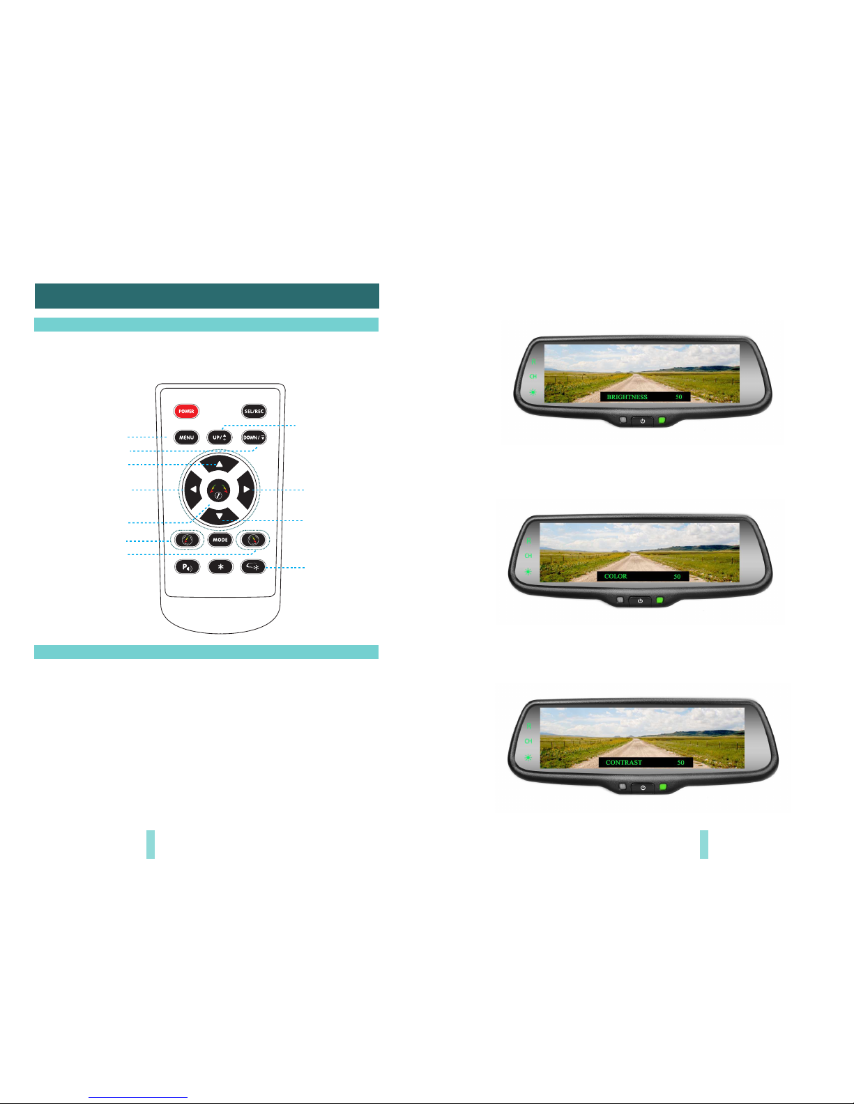
12 13
Chapter Four: Menu Setting
Enter pic ture menu
Guide line cl ockwise
Menu pa rameter de crease
Menu paramete r increas e
Guid e line up
Guid e line left
Enter g uide line
adju stment
Guide line ant i-clockwise
Guid e line right
Guid e line down
Pres s to res et all
menu a nd paramete rs
4.1 Remote control
The m enu onl y can be se t by remo te cont rol, an d kindl y check i ts defi nitio n as belo w.
4.2 Menu setting guidance
Short p ress “M EN U”to en ter “PI CT UR E”, then yo u can swi tch among
“BR IG HT NESS”, “COLOR”, “CONT RA ST ”, “S CA LE”, “START LOGO”, “PRESET”,
or enter out . W hen it sw itche s t o “PRESE T”, re-pre ss short ly the MENU , and
you woul d close the menu. U P and DOW N are to c hange the fi gure of each
set ting.
4.2.1 B RI GHTNE SS A DJUST MENT
The d efaulted s ett ing is 50 , ranging fr om 0 to 100 , and onl y CVBS si gnal ca n work.
4.2.2 C OLO R AD JUSTM EN T
The d efaulted s ett ing is 50 , ranging fr om 0 to 100 , and onl y CVBS si gnal ca n work.
4.2.3 C ONTRAST A DJUST MENT
The d efaulted s ett ing is 50 , ranging fr om 0 to 100 , and onl y CVBS si gnal ca n work.
Page 9
UP
Clockwise
Dow n
Rig ht
lef t
Move the guide line Rotate the guide line
anticlockwise
Press the button to choose the L or R adjustable guideline
Remote control
RL
Wrongposition
Right position
10 11
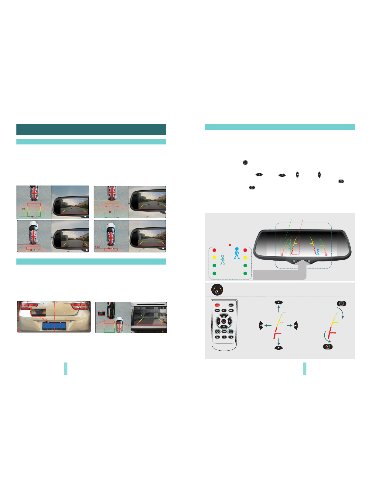
According to the site of standard reference line, we can put reference objects such
as desks in the back area of car. Compared with the marked reference objects, we
can adjust the sites and angle of two guide lines displayed on the monitor. You will
get the accurate and safety guide lines once they coincide with the reference
objects.
Press setting button is to enter into “guide line adjustment” mode. The system is
defaulted to adjust left guide line firstly. Press the button again will switch to adjust
the right guide line. The up , down left and right buttons are to
adjust the correspondent location of guide lines. The clockwise rotation and
contra rotation buttons are to adjust the angle of guide lines. It is easy to
operate and calibrate. After finishing calibration, switch the reverse gear to save
the information.
Caution: keep the remote control 0.5m-1.0m from rearview mirror when you use the remote to
adjust the parking lines.
3.3 How to adjust the guide line
Displayonthemonitor
Generally, to help drivers estimate the distance from obstacles, there are three
lines for reference -red, yellow and green. Those three lines are displayed on the
monitor when car is reversing. The green line is 3m from the back of car and the
yellow line is 2m. The distant red line is 1m from the backside of car while the
closed red line is 0.4m. Both reference lines on the left and right should leave
0.2m space from the car.
20CM20CM
3.1 About guide line
Regular guide line is fixed. But installation sites of cameras are different as well
as car size. The fixed guide line is not accurate enough for drivers. There will be a
great difference between regular and fixed guide lines and car's real guide lines,
especially when camera is mounted on the left or right side of car backside. It
may cause accidents.
3.2 What the regular guide line is
Chapter three: Adjustable Guideline
Page 10
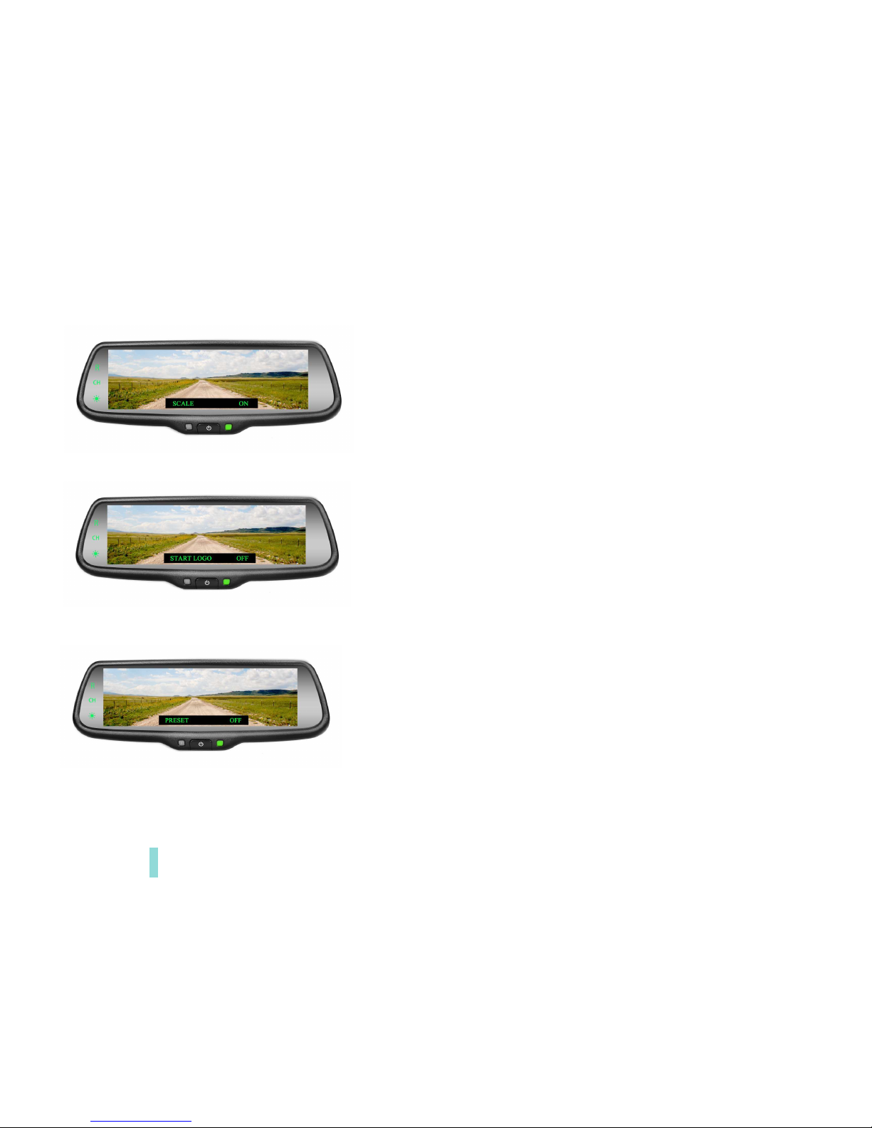
4.2.4 S CA LE ADJU STMENT
4.2.6 P RESET ADJ USTME NT
It' s on ly for the model wit h guide lin es, and no such sett ing for tho se with ou t
suc h funct ion. ON i s defaulte d setti ng, and y ou can ma nuall y set it to O FF.
4.2.5 S TART LO GO A DJUST ME NT
It' s d efaulted as OF F, and ON is to preset the me nu, then it sw itc hes to OFF
aut omati cally.
It' s is default ed as “ON ”, you ca n set it to “ OFF” ma nuall y.
The reve rsing mode is the top prior it y, the n all tou ch p anel is ine ffecti ve. The
vid eo cann ot be swi tch ed unti l the par king mo de is end ed. But t he manu al
but ton is acces sible . Shor t pres s is to adjust t he bri ghtne ss of the monit or, l ong
pre ss to tur n off the s creen .
14
 Loading...