

Page 1

User Manual
Software Version 1.70-68-18
Page 2

GLP® J
DC1 User Manual – Revision 3.0
This manual covers fixture software version 1.70-68-18
© 2017-2018 German Light Products GmbH. All rights reserved.
The marks ‘GLP’ and ‘German Light Products’ are trademarks registered as the property of German
Light Products GmbH in Germany, in the United States of America and in other countries.
The information contained in this document is subject to change without notice. German Light
Products GmbH and all affiliated companies disclaim liability for any injury, damage, direct or
indirect loss, consequential or economic loss or any other loss occasioned by the use of, inability to
use or reliance on the information contained in this document.
Head office:
German Light Products GmbH (GLP), Industriestrasse 2, 76307 Karlsbad, Germany
Tel (Germany): +49 7248 92719 - 0
Service & Support EMEA:
GLP, Industriestrasse 2, 76307 Karlsbad, Germany
Tel. (Germany): +49 7248 9271955
Email: [email protected]
www.glp.de
Service & Support USA:
GLP USA, 1145 Arroyo St., Ste. A, 91340 San Fernando, California
Tel (USA): +1 818 767 8899
Support (US): [email protected]
www.germanlightproducts.com
Page 3

Table of Contents
1. Safety ..................................................................................................... 5
Key to symbols ................................................................................. 5
General safety information ........................................................... 5
Electrical safety ............................................................................... 6
Fire safety and protection from burns ......................................... 7
Eye safety ......................................................................................... 7
Strobe safety .................................................................................... 8
Installation safety and protection from personal injury ............ 8
2. Avoiding damage ............................................................................. 10
Transportation and storage ........................................................ 10
3. Product overview .............................................................................. 11
4. Feature s ............................................................................................... 12
Beam ............................................................................................... 12
Color Plates .................................................................................... 12
DMX control modes ...................................................................... 12
Pixel grouping ................................................................................ 14
Pixel Orientation ............................................................................ 15
Tilt ..................................................................................................... 16
Barndoor tilt operation ................................................................. 16
Auto-Bl ack out ................................................................................ 16
Custom settings and factory defaults ....................................... 17
Dimming curves ............................................................................ 17
Behavior when a DMX signal is lost ............................................ 17
PWM frequency ............................................................................ 17
Effect offsets .................................................................................. 17
Flash control modes ..................................................................... 17
Dimmer flash control mode ........................................................ 18
FX ..................................................................................................... 18
Plate color priority ......................................................................... 19
Display ............................................................................................. 20
Cooling modes .............................................................................. 20
Fixture information ........................................................................ 20
Manual control .............................................................................. 20
Test sequences .............................................................................. 20
Service menu ................................................................................. 20
Clamp attachment ...................................................................... 20
5. Preparation for use ............................................................................ 21
Included items ............................................................................... 21
Page 4

Mounting ........................................................................................ 21
Mounting upright on a level surface ......................................... 22
Suspension or horizontal/angled truss mounting ..................... 22
Securing with a safety cable ...................................................... 23
Connecting to power .................................................................. 23
Installing power connectors ........................................................ 24
Main fuse ........................................................................................ 24
Connecting to a DMX control data link ................................... 25
Starting and stopping operation ................................................ 25
Transportation and Storage ........................................................ 25
6. Control menus and LCD display ..................................................... 26
7. Control menu layout ......................................................................... 28
8. DMX channels .................................................................................... 32
DMX Mode 1 (Compressed Pro), 14 DMX Channels .............. 33
DMX Mode 2 (Normal), 23 DMX Channels ............................... 38
DMX Mode 3 (Single Pixel), 68 DMX Channels ......................... 43
DMX Mode 4 (Single Pixel Pro), 62 DMX Channels .................. 49
DMX Mode 5 (Grouped Pixel Pro), 17 DMX Channels ............ 55
9. Plate FX patterns ................................................................................ 60
10. Beam FX patterns ............................................................................ 65
11. Cleaning and maintenance ......................................................... 68
Suggested maintenance intervals ............................................. 68
Cleani ng ......................................................................................... 68
GLP Service and Support............................................................. 68
12. Technical Specifications ................................................................ 69
Strobe panel LEDs ......................................................................... 69
Strobe tube LEDs ........................................................................... 69
Movement...................................................................................... 69
Connectors .................................................................................... 69
Operating conditions ................................................................... 69
Shipping options ............................................................................ 69
Dimensions and weight ............................................................... 69
13. Dimensi ons ........................................................................................ 70
Page 5

German Light Products®
1. Safety
Key to symbols
The following symbols are used in this manual:
Warning! Safety hazard.
Risk of severe injury or
death.
Warning! See user
manual for important
safety information.
Warning! Risk of eye
injury.
Warning! Fire hazard.
Warning! Hazardous voltage.
Risk of lethal or severe
electric shock.
General safety information
Read this section carefully before installing or using the product. If you have any
doubts or questions about how to use the product safely, contact your GLP® supplier
for assistance. Your GLP supplier will be happy to help. If necessary, contact an
authorized GLP distributor (see list of distributors at www.glp.de).
The JDC1 and this user manual are intended for use by experienced professionals with
the knowledge and skills to set up, operate, and maintain high-powered, remotely
controlled lighting equipment safely and efficiently. These operations require expertise
that may not be provided in this manual.
• Respect all warnings and directions given in this user manual and on the product.
Read this manual and familiarize yourself with the safety precautions it contains
before installing or using the product. The manufacturer will take no responsibility for
damages or harm resulting from disregard for the information in this manual.
• Check the GLP website at www.glp.de and make sure that you have the latest
version of this user manual. Check also that the software version indicated on page
2 of the user manual matches the version installed in the product. You can
download the correct version of this user manual if necessary.
• Make the user manual available to all installers and operators and save the manual
for future reference.
• Use the product only as directed in this user manual. Observe all markings in this user
manual and on the product.
JDC1 User Manual Rev. 3.0 5
Page 6

www.glp.de
• Refer any service operation not described in this manual and refer all repairs to a
technician authorized by GLP.
• The light source in this product may not be changed by the end user.
• Read and follow the user documentation for all additional equipment.
Electrical safety
• Do not allow the product to come into contact with water or moisture.
• Use only a source of AC mains power that complies with local building and
electrical codes and has both overload and ground fault (earth fault) protection.
• Ensure that the product is electrically connected to ground (earth).
• Disconnect the product from AC mains power before carrying out any installation or
maintenance work and when the product is not in use.
• Disconnect the product from power immediately if the power plug or any seal,
cover, cable, or other component is damaged, defective, deformed, wet or
showing signs of overheating. Do not reapply power until the product has been
repaired and made safe by a technician authorized by GLP.
• Before using the product, check that all power distribution equipment and cables
are in perfect condition and rated for the electrical requirements of all connected
devices.
• Use only Neutrik PowerCON TRUE1 cable connectors for AC mains power input at
the product’s power connector.
2
• Use minimum 14 AWG or 1.5 mm
power input and relay cables that are minimum
16 A rated and temperature-rated to suit the application. In the USA and Canada
the cables must be UL-listed, type SJT or equivalent. In the EU the cables must be
type H05VV-F or equivalent.
• The supplied power input cable is rated as follows:
- US power cable: 16 A, 14 AWG, UL listed, E304117, SJT, 4.9 ft.
- EU power cable: 16 A, 1.5 mm², H05VV-F, 1.5 m
• If a fuse blows, replace it with one of the original type and rating only. If new fuses
blow, disconnect the product from power and send it to a technician authorized by
GLP for repair.
6 JDC1
User Manual Rev. 3.0
Page 7

German Light Products®
Fire safety and protection from burns
• Do not operate the product if the ambient temperature (Ta) exceeds 45° C (115° F).
• The surface of the product’s casing can reach up to 160° C (320° F) during
operation. Avoid contact by persons and materials. Do not install the product in a
location where there is a risk of accidental contact. Allow the product to cool for at
least 20 minutes before handling
• Keep the product well away from flammable materials.
• Keep all combustible materials (e.g. fabric, wood, paper) at least 1 m (3.3 ft.) away
from the head.
• Ensure that there is free and unobstructed airflow around the product. Provide a
minimum clearance of 100 mm (4 in.) around fans and air vents.
• Do not illuminate surfaces within 1 m (3.3 ft.) of the product. The light output from
the product is powerful enough to cause burns or fire in illuminated objects at close
range.
• Do not install a fuse that has a higher rating than the one originally installed in the
product. Do not bypass fuses.
• Do not stick filters, masks or other materials onto the front glass. Do not block the
light output in any way. The front glass becomes extremely hot during operation and
can melt or ignite objects that are in contact with the surface. Ensure that the front
glass Is clean and unobstructed at all times in order to prevent a fire hazard and
damage to the product.
• The product’s optical components can focus the sun’s rays, creating a risk of fire
and damage. Do not expose the front of the product to sunlight or any other
intense light source, even from an angle.
Eye safety
• The JDC1 is classified as a Risk Group 3 lighting fixture according to EN 62471.
Possibly hazardous radiation emitted. Do not stare into the light output from the
product. May be harmful to the eyes.
• Do not look at the product’s light output with optical instruments or any device that
may concentrate the light output.
• Make sure that persons near to or working on the product are not looking directly
into the light output when the product lights up suddenly. This can happen when
power is applied, when the product receives a DMX signal, or when certain control
menu items are selected.
JDC1 User Manual Rev. 3.0 7
Page 8

www.glp.de
• The warning below is printed on the product. If the warning becomes impossible to
read, replace it with a label reproduced from this illustration:
• Provide well-lit conditions to reduce the pupil diameter of anyone working on or
near the product.
Strobe safety
• Flashing light, particularly at 5 - 30 Hz, may cause seizures in persons with
photosensitive epilepsy. Do not use strobe effects for extended periods.
• Comply with local regulations on the use of strobe lighting and notify the public in
advance with highly visible warning signs when strobe effects are used.
• If a seizure occurs, stop using strobe effects. Seek professional medical help. Note
the time that the seizure starts and finishes. Call emergency medical help urgently if
the seizure lasts more than five minutes, if it is the person’s first seizure, or if the person
is injured. While waiting for help to arrive, consider the following general advice for
caring for a person who is having a seizure: Protect the affected person from injuring
themselves on hard or sharp objects. If necessary, move the person to a safe place.
Lay them on their side with their head supported to prevent it from hitting the floor.
Loosen any tight clothing around their neck. Do not use force to hold the person or
restrict their movements. Do not put anything in their mouth, including your fingers.
Installation safety and protection from personal injury
• Installation must be performed by qualified personnel only and carried out in
accordance with applicable regulations such as DIN VDE 0711-217.
• The product is not portable when installed.
• Ensure that the supporting structure and installation hardware used can hold at least
10 times the weight of the load that they support.
8 JDC1
User Manual Rev. 3.0
Page 9

German Light Products®
• Suspend the product with hardware specifically designed and rated for the
purpose. Check that the hardware is in perfect condition. Fasteners must be steel
grade 8.8 strength or better. Rigging clamps must be half-coupler type that
completely encircle the rigging truss chord.
• Screws or bolts used for mounting hardware must protrude minimum 9 mm / 0.36 in.
and maximum 11 mm / 0.43 ins. into the threaded holes in the base of the fixture.
• If the product is installed in a location where it may cause injury or damage if it falls,
install as directed in this manual a safety cable or similar secondary attachment that
will hold the product if a primary attachment fails. The secondary attachment must
be approved by an official body such as TÜV as a safety attachment for the weight
that it secures, it must comply with EN 60598-2-17 Section 17.6.6, and it must be able
to support a static suspended load that is ten times the weight that it secures.
• Fasten the product to a structure or surface as directed in this user manual. Do not
use safety cables as the primary means of support.
• Before applying power to the product, ensure that the head can move through its
full range without risk of collision.
• Check that all covers and items of rigging hardware are secure before using the
product.
• Do not operate the product with missing or damaged covers, shields or any optical
component.
• Restrict access below the work area and work from a stable platform whenever
installing, servicing or moving the product.
• If the product becomes damaged, stop using it immediately and disconnect it from
power. Do not attempt to use a product that is obviously damaged.
• Do not modify the product in any way not described in this user manual.
• Install genuine GLP parts only.
JDC1 User Manual Rev. 3.0 9
Page 10

www.glp.de
2. Avoiding damage
Do not point the front of the fixture towards the sun or other strong light sources. Strong
light can cause internal damage to the fixture, melting components or starting an
internal fire within seconds.
Figure 1. Avoiding damage from light sources
Damage can occur whether the fixture is powered on or off. See Figure 1. Damage
can also occur if the light hits the front of the fixture at an angle: the fixture does not
need to be pointing directly at the sun or other light source.
To avoid problems from strong light sources:
• Do not expose the front of the fixture to sunlight or any other strong light source.
• For outdoor applications during daylight, make sure that the front face of the fixture
is shielded or points away from the sun, even when not in use.
• Avoid pointing other high-powered beam lights directly at the fixture.
Do not pick up or carry the fixture by the head. The LCD display is also fragile. Picking
up or supporting the fixture in these spots could result in damage that is not covered by
the warranty.
Use only original spare parts. Do not make any structural modifications to the fixture or
you will void the product warranty.
Clean optical components only as directed. Oils, solvents, and other chemicals
commonly used for cleaning can damage the lens coatings and surfaces.
Do not drop the fixture or expose it to mechanical stress.
Do not expose the fixture to heat (from other lighting fixtures for example).
Transportation and storage
Transport the fixture either in a flightcase or in its original packaging to protect it from
damage caused by shocks during transportation.
Store the fixture in a dry location when not in use.
10 JDC1
User Manual Rev. 3.0
Page 11

German Light Products®
3. Product overview
1 2
9
8
7
56
Figure 2. Product overview
1 – Fuseholder
2 – Head
3 – Alignment pin lever
4 – Alignment pins
5 – DMX thru (out)
6 – Control panel
3
4
7 – AC mains power in (Neutrik powerCON TRUE1)
8 – DMX in
9 –Tilt lock lever
JDC1 User Manual Rev. 3.0 11
Page 12

www.glp.de
4. Features
The impression JDC1 from GLP represents a whole new class of moving head
combined strobe/color effect lighting fixture. It delivers unprecedented levels of bright,
cool white light output combined with a full-face color wash panel that uses 1320 highquality RGB LEDs. The strobe tube and the color panel can each be split into 12
segments with individual control, and the whole array can be fully pixel mapped
through any standard controller. Strobe and color effects can be controlled
separately, but they can also be combined for stunning strobe, blinder and wash
effects. The JDC1 also features a fast-action moving head with 16-bit control and a
185° tilt range.
The JDC1 is designed for permanent or temporary indoor use. It can be used outdoors
if it is protected from moisture and precautions are taken to prevent damage from
direct sunlight. It may be placed upright on a level surface or suspended from a
suitable structure as described this manual.
The JDC1 is not suitable for household use, for use in any location where unattended
children have access to it, or for use in permanent outdoor installations.
Beam
The JDC1 features a traditional central single-tube element, the Beam, containing 216
cool white LEDs that produce powerful white light.
You can run powerful shutter effects (including a strobe at up to 16.67 Hz) and
dynamic FX patterns on the Beam, or you can operate it continuously to give highoutput blinder and wash effects with an 86° beam angle. If you set an intensity on the
Beam, it will be used as the background intensity if you run a shutter effect or FX
pattern on the Beam.
You can control the Beam as one unit or divide it into 12 segments that you can use as
separately controllable pixels.
Color Plates
The JDC1 has two RGB color panels – the Plates – on either side of the central Beam
tube. Each Plate contains 660 RGB LEDs.
You can run a wide range of color effects including shutter / strobe effects and
dynamic FX patterns on the Plates, or you can operate them continuously using RGB
color mixing to provide a wide (148°) color wash. If you set a color mix on the Plates, it
will be used as the background color if you run a shutter effect or FX pattern on the
Plates.
You can control the Plates as one unit or divide them into 12 segments that you can
use as separately controllable pixels.
DMX control modes
Five DMX control modes are available in the JDC1. All five modes offer the same
functions on DMX channels 1-14. DMX Mode 1 offers the standard functions on
channels 1-14 only, while DMX Modes 2-5 offer additional functions using additional
DMX channels.
12 JDC1
User Manual Rev. 3.0
Page 13

German Light Products®
The following DMX modes are available:
• DMX Mode 1 (Compressed Pro) uses 14 DMX channels. It gives the following control
options that are used as standard in all DMX modes:
- 16-bit control of tilt, allowing the head to be tilted through 185°, using channels 1
and 2.
- Beam shutter effects (strobe, ramp up/down etc.) with variable intensity, duration
and rate using channels 3-6.
- Adjustment of a range of fixture settings from the DMX controller using the Special /
Control commands on channel 7.
- Plate shutter effects (strobe, ramp up/down etc.) with variable intensity, duration
and rate using channels 8-11.
- RGB color mixing on the Plates using channels 12-14.
• DMX Mode 2 (Normal) uses 23 DMX channels. It gives the following control options:
- Standard control options on DMX channels 1-14.
- Pre-programmed dynamic FX patterns on the Beam and the Plates, with
adjustment of FX speed and of crossfades between the FX and the background
using channels 15-19.
- Master intensity and RGB color mixing on the Plates using channels 20-23.
• DMX Mode 3 (SPix) uses 68 DMX channels. It gives the following control options:
- Standard control options on DMX channels 1-14.
- Pre-programmed FX patterns using channels 15-19.
- Master intensity and pixel-level RGB color mixing of Plate pixels 1-12 using channels
20-56.
- Pixel-level white intensity control of Beam pixels 1-12 using channels 57-68.
For pixel layout in the JDC1, see Figure 4 on page 14.
• DMX Mode 4 (SPix Pro) uses 62 DMX channels. It gives the following control options:
- Standard control options on DMX channels 1-14.
- Pixel-level RGB color mixing of Plate pixels 1-12 using channels 15-50.
- Pixel-level white intensity of Beam pixels 1-12 using channels 51-62.
• DMX Mode 5 (1Pix Pro) uses 17 DMX channels. It gives the following control options:
- Standard control options on DMX channels 1-14.
- Grouped RGB color mixing of the Plates using channels 15-17.
JDC1 User Manual Rev. 3.0 13
Page 14

www.glp.de
Pixel grouping
The JDC1 gives two LED pixel grouping options, depending on which DMX mode the
fixture is in:
• Control of the Beam as one unit and control of both the Plates as one unit (see
Figure 3).
• Control of the Beam as 12 separate pixels and control of the Plates as 12 separate
pixels (see Figure 4).
Plate LEDs
Beam LEDs
Plate LEDs
Figure 3: LEDs grouped into Beam and Plate
1st Plate LEDs
Beam LEDs
2nd Plate LEDs
Pixels are numbered as seen when looking
at the front of the fixture with Tilt set to 000.
Figure 4. LEDs grouped into pixels
14 JDC1
User Manual Rev. 3.0
Page 15

German Light Products®
Pixel Orientation
Figure 4 on the previous page shows the default pixel layout on the Plates. The default
pixel orientation setting is:
• Pixel Orientation = OFF (Normal)
• 2nd Plate pixel Orientation = OFF (Normal).
You can invert pixel orientation by either sending a DMX command on the Special
/Control DMX channel 7 or using the Settings menu in the control panel. Inverting pixels
lets you set up symmetrical effects in multiple fixtures quickly without the need to
reprogram cues.
See Figure 5. You can invert the order of all the pixels on the Plates and the pixels in the
Beam by setting pixel orientation to ON (Inverted). Inversion status in the control panel
display will change from NNN (tilt, pixel orientation and 2nd Plate pixel orientation all
Normal) to NIN (tilt Normal, pixel orientation Inverted, 2nd Plate pixel orientation
Normal) and the pixel layout will be as shown below:
Figure 5. Pixel orientation = ON (Inverted), 2nd Plate pixel orientation = OFF (Normal)
See Figure 6. You can invert the order of the pixels on only the second Plate by setting
only 2nd Plate pixel orientation to ON (Inverted). Inversion status in the control panel
display will be NNI and the pixel layout will be as shown below:
Figure 6. Pixel orientation = OFF (Normal), 2nd Plate pixel orientation = ON (Inverted)
JDC1 User Manual Rev. 3.0 15
Page 16

www.glp.de
See Figure 7. You can invert the order of all the pixels on the Plate and at the same
time invert the order of the pixels on the second Plate by setting Pixel orientation to ON
(Inverted) and 2nd pixel orientation to ON (Inverted). Inversion status in the control
panel display will be displayed as NII and the pixel layout will be as shown below:
Figure 7. Pixel orientation = ON (Inverted), 2nd Plate pixel orientation = ON (Inverted)
Tilt
The head tilts through 185° with coarse and fine control channels and self-correcting
position feedback.
Using the control panel, you can disable tilt position feedback and you can invert tilt
direction. Inverting tilt is a fast way of creating symmetrical effects in multiple fixtures.
You can also set tilt operation to one of three options:
• Enabled with DMX control.
• Disabled.
• Enabled but without DMX control. In this setting, power is applied to the tilt motor
but the fixture will not respond to movement commands sent via DMX. The tilt motor
will therefore act as a brake and hold the head in position.
Barndoor tilt operation
If you mount barndoors or any other accessory on the front of the fixture, set Barndoors
to ON either on the Special / Control channel using DMX or in the Tilt menu using the
control panel. Barndoor tilt operation reduces tilt speed to avoid any damage that
could be caused to barndoors, if fitted, by sudden tilt movements.
Auto-Blackout
To avoid any possibility of unexpected behavior from a powerful strobe in the middle
of a show or event, you can use the Shutter menu in the control panel to set the fixture
to black out automatically if it detects an internal error. If this happens, the error will be
listed in Information – System Errors in the control panel.
You can also set the fixture to black out automatically if more than three seconds
passes without the fixture receiving a valid DMX signal.
16 JDC1
User Manual Rev. 3.0
Page 17

German Light Products®
Custom settings and factory defaults
The Init Positions menu in the control panel lets you replace the fixture’s factory default
settings with any custom settings (DMX Mode, pixel orientation, etc.) that you have
stored using the control panel or via DMX. If you apply an Init Positions – Save
command, the fixture will return to these custom settings after a power off/on cycle or
after a reset.
You can delete all saved custom settings at once and return to the factory default
settings using an Init Positions – Reset command.
Dimming curves
See illustration on right. Three dimming curves are
available: Linear, Soft, and Extra soft. You can
select a curve using the control panel or using
the Special / Control DMX channel.
Behavior when a DMX signal is lost
You can choose how the fixture behaves if it is
receiving a DMX signal but the signal stops. Three
options are available in the DMX Hold menu in
the control panel: the fixture can:
• black out immediately,
• fade down to a blackout, or
• continue obeying the last DMX command it received.
PWM frequency
You can adjust the PWM frequency of the LEDs from 582 to 618 Hz in 1 Hz increments, or
you can set the PWM frequency to 1200 or 2400 Hz.
Effect offsets
Effect offsets are a fast way to set up effect chases in multiple fixtures. You can set
effect offsets with starting points in the effect cycle from 10° to 360° in 10° increments.
You can set an offset for the Beam on channel 7 and set an offset for the Plates on
channel 11 in all DMX modes.
Any offset that you set will apply to the standard shutter effects available in all DMX
modes and also the FX patterns available in DMX Modes 2 and 3.
Flash control modes
The JDC1 offers three flash control modes that can be selected either in the control
menus or via DMX on the Special / Control channel:
In Normal flash control mode, you set the rate and duration of Beam and Plate flashes
on their respective rate and duration channels. If you increase the flash rate, the
duration of flashes will not change but the intervals between flashes will become
shorter. Normal flash control mode gives you full control over flash duration, but it
means that you may need to adjust flash duration if you change the flash rate.
JDC1 User Manual Rev. 3.0 17
Page 18

www.glp.de
In Percentage flash control mode, you set the duration of Beam and Plate flashes on
their respective duration channels as a percentage of the flash on/off cycle. Once
you have set this percentage, flash duration is automatically adjusted to match flash
rate. If you increase the flash rate, the duration of flashes will be reduced. Percentage
flash control mode makes it easy to control flashes using the rate channel only.
In Aggressive flash control mode, flash rate and duration are controlled as in Normal
flash mode, but if intensity on the Plates is below 100%, the extra available power is
pushed to the Beam LEDs. This gives an even more powerful Beam flash than in the
other flash modes.
If Plate LEDs are at zero intensity, enabling Aggressive flash mode will give maximum
Beam flash intensity. If you increase Plate intensity, Beam and Plate output will be
balanced to give the best performance. If you set Plate intensity to maximum, Beam
intensity will be the same as in Normal flash mode.
Flash Modes can be changed very quickly (hold for 0.5 seconds) by programming the
setting in the cue directly. This means that it is possible to swap between flash modes in
the middle of a show.
Dimmer flash control mode
Producing single flashes is quick and easy if you activate Dimmer Flash mode in the
Settings control menu. Activating this mode affects both the Beam and the Plates.
With Dimmer flash mode enabled, if the Shutter channel (6 for the Beam and 10 for the
Plates) is set to zero, any new DMX value that you input on the Intensity channel (3 for
the Beam and 8 for the Plates) will produce a single flash on the Beam or Plates. In
effect, all you need to do is 'nudge the dimmer fader' to produce a flash.
FX
DMX Modes 2 and 3 include pre-programmed FX on channels 15-19. The FX are
dynamic patterns that are superimposed onto the Beam and/or the Plate LEDs.
Normally, all the Beam or all the Plate pixels flash at the same time. But when you
select an FX, only the pattern pixels flash.
The following control options are available via DMX when using FX:
• Select FX pattern and speed for the Beam
• Select FX pattern and speed for the Plates
• Adjust crossfade time (fade time between FX pattern and background).
For tables showing all the patterns available on the Beam and the Plates, see pages 60
and 65.
18 JDC1
User Manual Rev. 3.0
Page 19

German Light Products®
Plate color priority
The JDC1 lets you set an RGB color for strobe flashes and FX patterns that are
superimposed on the Plates as well as setting an RGB color for the background on the
Plates. You can choose from three options that define how strobe flash and FX pattern
colors are superimposed over background colors using the settings available via DMX
on channel 7:
• FX Pattern Priority: A strobe flash or FX pattern on the Plates will always use the
FX/flash color and override the plate background color.
For example, if you have created a 100% intensity red FX or flash and a 50% intensity
green background, the FX or flash will always be visible as 100% intensity red over a
50% intensity green background.
• Color Mix: A strobe flash or FX pattern on the Plates will mix with the plate
background color using additive color mixing. The color of the FX pattern or flash will
change if you adjust the FX pattern / flash color, and it will also change if you adjust
the plate background color.
For example, if you have created a 100% intensity red FX or flash and a 50% intensity
green background, the FX or flash will appear as 100% intensity yellow over a 50%
intensity green background.
• Background Color: An FX pattern or flash on the Plates will only be visible if no
background color is set on the Plates. If a background color is set on the Plates, the
FX pattern or flash will use the plate background color.
For example, if the fixture is in Background Color mode and you have:
- created a 100% intensity red FX or flash, and
- created a 50% intensity green background,
then the FX or flash will be not visible: you will only see the 50% intensity green
background. However, if you dim the background intensity down to zero, you will
see the 100% intensity red FX pattern or flash.
The Plate Color Priority settings can help you set up interesting effects when the Plates
are controlled as one pixel, but they can give even richer, more complex effects when
the Plates are controlled as twelve separate pixels. In Color Mix and Background Color
modes, setting different Plate pixels to different colors and intensities will affect the
appearance of any FX patterns or flashes that are superimposed on those pixels.
For example, if the fixture is in Background Color mode and you have:
• created a 100% intensity red FX or flash,
• set even-numbered pixels (2, 4, 6, etc.) to zero intensity, and
• created a 50% intensity green background on odd-numbered pixels,
then the FX or flash will only be visible on the even-numbered pixels. On the oddnumbered pixels you will only see the 50% intensity green background.
JDC1 User Manual Rev. 3.0 19
Page 20

www.glp.de
Display
The illuminated graphic LCD display with self-charging battery lets you change fixture
settings even when the power is off. See Chapter 6 for settings, readouts, and related
information.
You can adjust the contrast and brightness of the display in the Display menu in the
control panel. You can also invert the display for easier reading if the fixture is flown
head-down in a rig, and you can set the display to flash if the DMX signal to the fixture
is lost, giving a discreet indication of DMX signal status.
Cooling modes
Cooling fans can be set to one of two modes:
• Auto for temperature-regulated operation. This mode optimizes cooling for
quietness.
• High for constant high-speed operation. This mode minimizes the possibility that the
fixture will reduce its light output if it exceeds thermal safety limits. This will normally
only happen when the fixture is worked hard for extended periods in high ambient
temperatures.
Fixture information
The Information menu in the control panel gives access to a long list of information
items. You can see a list of any internal errors that the fixture may have detected,
check main and distributed software and hardware versions, check temperature
sensor readouts, see logs of operating hours and boot count and check whether the
fixture is running on AC mains or battery power.
You can monitor the DMX values being received on the main DMX channels, and you
can monitor cooling fan operation.
Manual control
The Manual Control menu in the control panel lets you reset the entire fixture, reset tilt
only, or reset left or right LED drivers only. It also lets you control the main functions of
the fixture without DMX.
Test sequences
The Test menu lets you run test sequences to ensure correct operation of Tilt movement
only, color output from the RGB LEDs on the Plates only, or the entire fixture.
Service menu
The Service menu is password-protected and is intended for use by GLP Service.
Clamp attachment
The base provides Camlock attachment points for easy fastening of an omega clamp
attachment bracket that accepts two half-coupler clamps.
20 JDC1
User Manual Rev. 3.0
Page 21

German Light Products®
5. Preparation for use
Warning! Read ‘Safety’ starting on page 5 for important safety information
that you must understand before you install or operate the fixture.
Included items
The JDC1 is supplied with a power cord with Neutrik powerCON TRUE1 connector and
an omega bracket (Part No. 87036) that lets you fasten two half-coupler rigging
clamps to the fixture.
Mounting
Figure 8: Mounting options (safety cable not shown)
The JDC1 may be rigged in any orientation or placed on a level surface. When
installing, keep the head at least 1 m (3.3 ft.) from flammable materials including
curtains and stage scenery.
JDC1 User Manual Rev. 3.0 21
Page 22

www.glp.de
Mounting upright on a level surface
The JDC1 may be placed upright on a level surface.
Make sure that persons cannot accidentally touch the
fixture when it is installed.
See illustration on right. You can align fixtures side by
side by inserting the alignment pins (arrowed) on the
right-hand side of one fixture into the holes on the lefthand side of the next fixture.
Figure 9: Alignment pins
Suspension or horizontal/angled truss mounting
You can fasten the JDC1 to a rigging truss with the head hanging vertically
downwards, or you can fasten the JDC1 to a truss horizontally or at any angle. To
fasten to a truss:
Bolt two suitable half-coupler rigging clamps to the supplied omega clamp
attachment bracket.
Figure 10: Camlock sockets
See illustration above. Fasten the omega bracket to the base of the fixture with
four Camlock quarter-turn fasteners by lining up the pins in the fasteners with the
keyways in the sockets, inserting the pins into the sockets and turning a full 90°
clockwise to lock them.
Fasten the rigging clamps securely around a chord on a rigging truss or similar bar.
Secure as directed below.
22 JDC1
User Manual Rev. 3.0
Page 23
German Light Products®
Securing with a safety cable
If the fixture can cause injury or damage if it falls, secure it with a secondary
attachment such as a safety cable that is approved for the weight of the fixture as
soon as you have fastened it in position.
To secure the fixture:
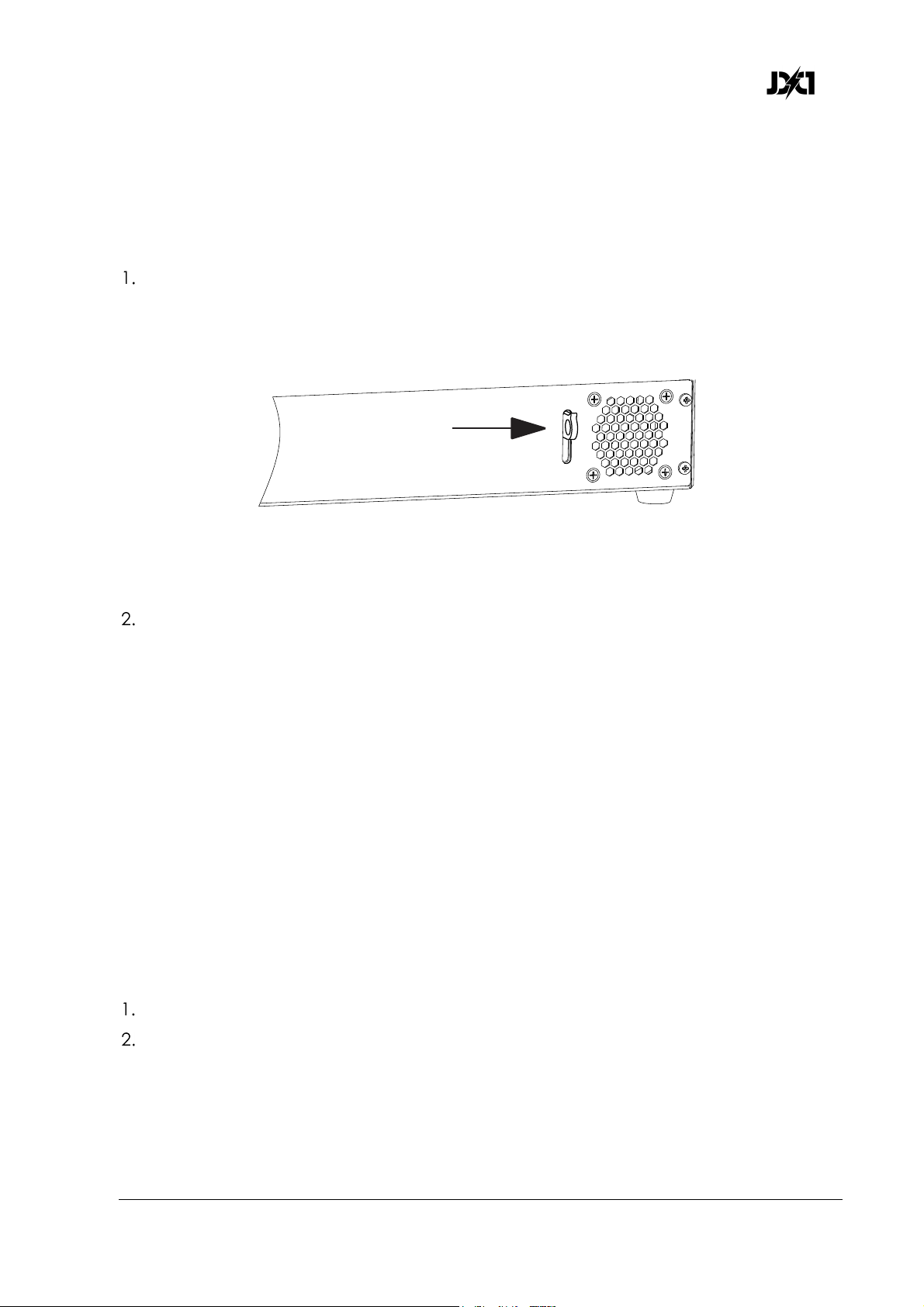
See illustration below. Attach a safety cable to the safety cable attachment point
in the fixture base and loop it around the truss chord or bar so that it will hold the
fixture if one or both of the rigging clamps fail. Take up as much slack as possible in
the safety cable (by looping it more than once around a truss chord, for example).
Figure 5: Safety cable attachment point
Make sure that the fixture is secure and that the head will not collide with any
objects when it tilts.
Connecting to power
The AC mains power supply must include a connection to ground / protective earth. It
must be protected against ground / earth leakage and overload. The autosensing
power supply accepts AC power at 100-240 V, 50/60 Hz. Do not connect the fixture to
power at any other voltage or to an external dimmer.
The JDC1 does not have a power ON/OFF switch. Power is applied to the fixture as
soon as the power cable becomes live.
The JDC1 has a 3-conductor Neutrik powerCON TRUE1 socket that accepts AC power
from a TRUE1 female cable connector. Although TRUE1 connectors support hotplugging, it is still good practice to shut down power to power cables or move Power
ON/OFF switches to OFF before connecting power cables to fixtures.
To connect the fixture to power:
If possible, shut down power to the power input cable.
See Figure 2 on page 11. The Neutrik powerCON TRUE1 AC mains power input
socket is located on the base of the fixture. Note the position of the keys and
keyways on the TRUE1 connectors. Line them up carefully, then connect the power
input cable to the power input socket by inserting the cable connector and
twisting clockwise to lock.
JDC1 User Manual Rev. 3.0 23
Page 24
www.glp.de
Check that the head is unlocked and can move freely and check that nobody is
looking directly into the front of the fixture. Apply power to the fixture by energizing
the power cable.
To disconnect the power cable, pull the latch on the cable connector outwards to
release it, then twist the connector counterclockwise and remove it from the socket.
Installing power connectors
It is possible to install a cord cap / mains power plug that is suitable for your local
convenience receptacles / mains power sockets on the supplied power input cable. If
you do this, check that the cord cap / plug is rated minimum 250 V, 16 A, that it has a
connection to ground / earth and that it has an integral cable grip. Follow the cord
cap / plug manufacturer’s assembly instructions.
If you need to install a Neutrik powerCON TRUE1 connector on a power cable, follow
the instructions given in the Support area of the Neutrik website at www.neutrik.com.
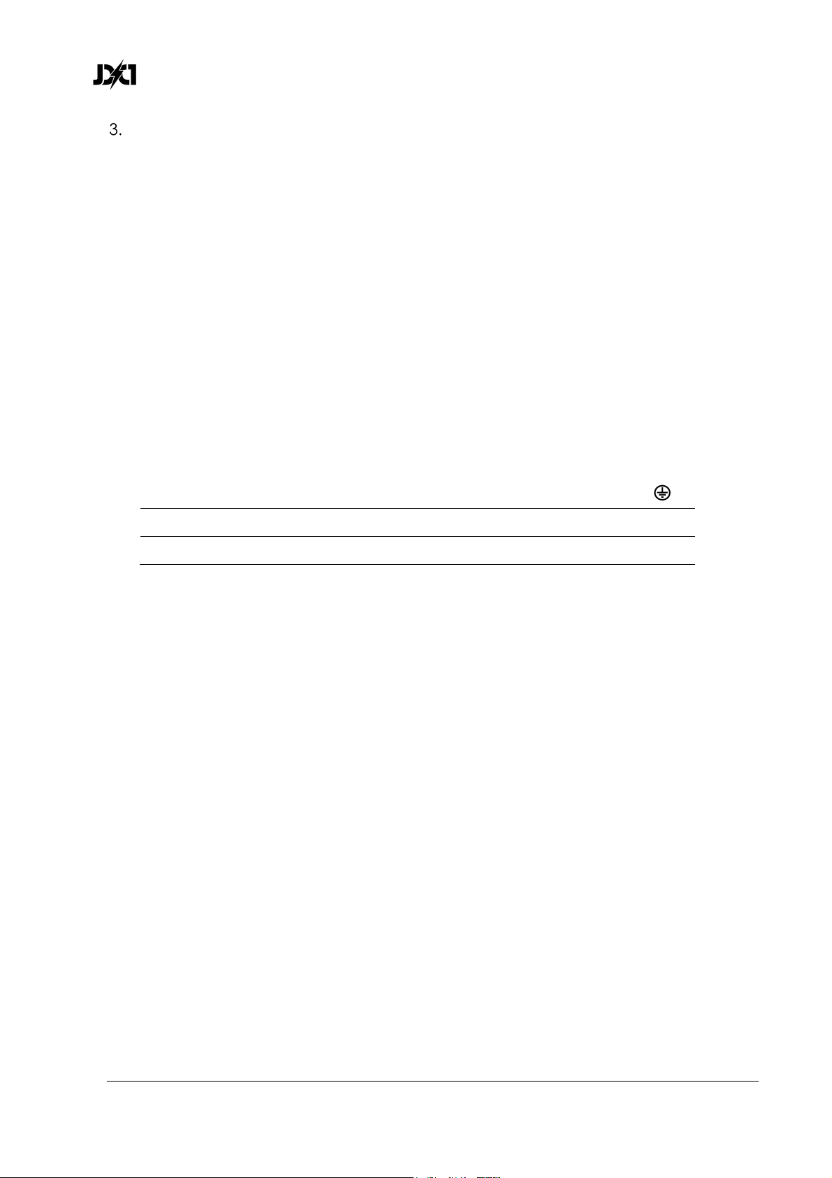
Respect the color coding used in the supplied power cable and in your local mains
power wiring system. US and EU systems use the color coding shown below:
Live or L Neutral or N
Ground / Earth or
US system Black White Green
EU system Brown Blue Yellow/green
Main fuse
See Figure 2 on page 11. The main fuse sits in a holder in the base.
If the fixture appears to be completely shut down even though power is applied, the
main fuse may have blown. Disconnect the fixture from power before replacing the
fuse. Replace only with a fuse of the same type and rating.
24 JDC1
User Manual Rev. 3.0
Page 25

German Light Products®
Connecting to a DMX control data link
The JDC1 provides 5-pin XLR IN and THRU sockets for connection to a USITT DMX512
data link.
Connectors use standard DMX pinout:
• Pin 1 = Ground
• Pin 2 = Negative / data cold
• Pin 3 = Positive / data hot.
• Pins 4 and 5 are not used.
If you would like any advice with planning and installing a DMX link, your GLP supplier
will be happy to provide assistance.
Starting and stopping operation
Warning! Before you apply power to the fixture or operate it after a
blackout, make sure that nobody is looking directly into the front glass from
close to the fixture.
Check that the tilt lock has been released before operating the fixture.
The JDC1’s TRUE1 AC mains power input connector supports hot-plugging, and it can
be quickest to disconnect a live power cable if you need to shut down power urgently,
but it may still be wise to show caution and connect and disconnect power cables
without power applied. Apply power to the AC mains circuit to start operation. Shut
down power to the AC mains circuit to stop operation.
Transportation and Storage
We strongly recommend that you transport the JDC1 either in a flightcase or in its
original packaging to protect it from damage caused by shocks during transportation.
Lock the head in the horizontal position for transport by sliding the tilt lock lever to the
locked position. The position of the tilt lock lever is shown in Figure 2 on page 11.
When the fixture is not installed, disconnect it from power and store it in a dry location.
JDC1 User Manual Rev. 3.0 25
Page 26

www.glp.de
6.
Control menus and LCD display
Warning! DMX control is disabled when the control menus are active. Be
prepared for the head to tilt and for the fixture to emit strong light as soon
as you exit the control menus.
The control panel and LCD display provide access to user settings, readouts and
utilities, including manual control and a test routine.
V:1.70/NNN/M03/EN 600
001
DMX Start Address
Mode Enter Down UP
-068
Next
069
O O
Figure 11. Main menu
See Figure 11. From left to right, the top line of the main menu displays:
• Main CPU software version
• DMX control modes for tilt, all pixels orientation and Plate 2 pixels orientation:
N(ormal) or I(nverted)
• DMX mode number
• Dimming mode: L(inear), S(oft), or E(xtra Soft)
• Flash mode: N(ormal) or (P)ercentage
• PWM frequency in Hz
For example, if the top line reads “V:1.70/NNN/M03/EN/600”, then:
• The main CPU software is version 1.70,
• DMX control of tilt is set to Normal, Plate pixels orientation is set to Normal, and 2nd
Plate pixels orientation is set to Normal,
O
O
• DMX mode 3 (MO3) is selected,
• Dimming mode is set to Extra soft,
• Flash mode is set to Normal, and
• PWM frequency is set to 600 Hz.
26 JDC1
User Manual Rev. 3.0
Page 27

German Light Products®
The fixture also displays its DMX start address and indicates which DMX channels it uses
and which DMX channel is available as the start address for the next fixture on the
DMX link.
When the fixture boots up, the panel displays fixture information including component
firmware and hardware versions and fixture hours before displaying the PCB reset
status screen. After resetting, the panel displays the main menu.
The bottom row of the display shows the functions of the four control buttons. Press the
Mode button to escape and return to the top of the menu. Press the Enter button to
select a setting, issue a command, or enter a submenu. Press the Down and Up buttons
to scroll through menu options.
To return resettable counters to zero, press and hold Enter for 3 seconds with the
counter displayed.
DMX control is disabled when the control menus are active.
A flashing display indicates loss of DMX.
JDC1 User Manual Rev. 3.0 27
Page 28
www.glp.de
7. Control menu layout
Menu Selection Value Remarks
DMX Start Address 1-512
Setup
DMX Mode
M01 COMPRESS -
M02 NORMAL M03 SPIX M04 SPIXPRO M05 1PIXPRO -
Settings
Tilt
Invert Tilt ON/OFF
Reset Tilt ON/OFF
Position Feedback ON/OFF
Barndoor ON/OFF
ON
Tilt Enable
Shutter
Error Blackout ON/OFF
No DMX Blackout ON/OFF
Init Positions
Save Reset Dimming Curve
Linear Soft -
Extra Soft -
DMX Hold
Off Fade Out -
Hold PWM Frequency
582-618 Hz 1200 Hz 2400 Hz -
Pixel Orientation
Second Pixel Orientation
OFF
NC
INVRS/
NORM
INVRS/
NORM
Set the DMX start address
Compressed 14-channel mode
Normal 23-channel mode
High resolution 68-channel mode
High resolution 62-channel mode
Low resolution 17-channel mode
Invert tilt control
If set to OFF, tilt movement will not
reset if fixture resets
Enable/disable tilt position feedback
Reduces tilt speed to protect
barndoors etc.
Tilt enabled and DMX controllable
Tilt disabled
Tilt enabled, not DMX controllable
Blackout if internal error detected
Blackout if no DMX for 3 seconds
Save as initial positions
Restore default positions
Select dimming curve
Behavior if no DMX signal received
Blackout on loss of DMX
Fade out on loss of DMX
Hold state on loss of DMX
Adjust PWM frequency for all LEDs
Default = 600 Hz
Numbering of all plate and all beam
pixels (OFF = normal, ON = inverted)
Numbering of plate pixels 7-12 only
(OFF = normal, ON = inverted)
28 JDC1
User Manual Rev. 3.0
Page 29
German Light Products®
yp
PCT
Flash Mode
Dimmer Flash ON/OFF
NORM
AGGER
Strobe
Color
Percentage flash mode
Normal flash mode
Aggressive flash mode
Dimmer Flash mode
FX patterns and flashes use Plate
FX/flash color
FX patterns and flashes use mix of
Plate Color Priority
Display
Contrast 0-100%
Brightness 0-100%
Blackout Time 1-30 s
Display Orientation
No DMX Flash ON/OFF
Temperature Unit °C/°F
Fan Mode
Auto High Reset Factory Settings Yes/No
Information
System Errors List
System Versions
Main
Temperatures
Current °C/°F
Max. Resettable °C/°F
Max. Non-resettable °C/°F
Current °C/°F
Max. Resettable °C/°F
Max. Non-resettable °C/°F
Fixture Information
Total hours hours
Resettable hours hours
Tilt
NM-LED A
NM-LED B
NM-LED C
NM-LED D
Main Temperature
LED Temperature
Fixture Hours
Boot Count
Color Mix
Background
color
Normal
Inverted
SW/HW
SW/HW
SW/HW
SW/HW
SW/HW
SW/HW
count
Plate FX/flash color and background
color if a background color is active
FX patterns and flashes uses Plate
background color if a background
color is active
Adjust control panel display
Default = 50%
Default =100%
Display sleep (seconds after last
ke
ress)Default = 10 s
Normal display
Inverted display
Display flashes if loss of DMX
Temperature-controlled fan speed
Maximum cooling
Reset all values except serial number
Display recent errors
Display software and hardware
versions in the fixture’s modules
Current base temperature
Max. temperature since last reset
All time maximum temperature
Current LED temperature
Max. LED temperature since last reset
All time maximum LED temperature
Total hours of operation
Hours of operation since last reset
Total number of power-ons
JDC1 User Manual Rev. 3.0 29
Page 30
www.glp.de
Fixture Status
DMX Input Monitor
Fans Monitor
Manual Control
Reset
Manual DMX
Power State
Tilt
Special / Control
Beam FX Shutter
Beam Dimmer
Beam Duration
Beam Rate
Color Shutter
FX Color Dimmer
Color Duration
Color Rate
Plate Red
Plate Green
Plate Blue
FX Crossfade
Pattern Color Movement
Pattern Select Color
Pattern Beam Movement
Pattern Select Beam
Master Pix Intensity
PSU Fan
Head Fan
Full System Reset
Tilt Reset
NM_LED L Driver
NM_LED R Driver
Tilt
Special / Control
Beam FX Shutter
Beam Dimmer
Beam Duration
Beam Rate
Color Shutter
Color Dimmer
Color Duration
Color Rate
FX Color Dimmer
Plate Red
Plate Green
Plate Blue
FX Crossfade
Pattern Color Movement
BAT/PO
0-255
0-255
0-255
0-255
0-255
0-255
0-255
0-255
0-255
0-255
0-255
0-255
0-255
0-255
0-255
0-255
0-255
0-255
0-255
RPM/V
RPM/V
YES/NO
YES/NO
YES/NO
YES/NO
0-255
0-255
0-255
0-255
0-255
0-255
0-255
0-255
0-255
0-255
0-255
0-255
0-255
0-255
0-255
0-255
Fixture on battery or AC mains power
Shows current DMX values for each
effect
Shows fan speed and voltage
Reset options
Enter control values to control each
effect (new values received via DMX
override manually entered values)
30 JDC1
User Manual Rev. 3.0
Page 31
German Light Products®
Test
Tilt ON/OFF
Color ON/OFF
All ON/OFF
Service
Reserved for GLP Service
Pattern Select Color
Pattern Beam Movement
Pattern Select Beam
Master Pix Intensity
Reset All Values
0-255
0-255
0-255
0-255
YES/NO
Enter control values to control each
effect (new values received via DMX
override manually entered values)
Set all manual DMX values to 0
Run test of functions
Table 1 Control Menus
Default settings are written in BOLD type.
JDC1 User Manual Rev. 3.0 31
Page 32

www.glp.de
8. DMX channels
The JDC1 can be operated in five different DMX modes that use from 14 to 68
channels. The commands for each mode are listed in the following tables.
The layout of channels 1-14 is the same in each mode.
Where commands are marked with an asterisk
zero and then send the DMX value continuously for 3 seconds (unless a different
duration is stated) to apply the command.
*
you must start from DMX value
32 JDC1
User Manual Rev. 3.0
Page 33
German Light Products®
DMX Mode 1 (Compressed Pro), 14 DMX Channels
Tilt, Beam shutter, special/control, Plates shutter, Plates grouped RGB
DMX
Channel Command
1 Coarse Tilt (MSB) 0-185° 0-255 0-100% 127 Fade
2 Fine Tilt (LSB) Coarse tilt + 0-1.2° 0-255 0-100% 127 Fade
3 Beam Intensity Intensity 0-100% 0-255 0-100% 0 Fade
4 Beam Duration Flash duration 7-650 ms 0-255 0-100% 255 Fade
5 Beam Rate Flash rate 0.289-16.67 Hz 0-255 0-100% 255 Fade
No effect 0-36 0-14.0% 0 Snap
Ramp up (= fade on, snap off) 37-40 14.5-15.5%
Ramp up random 41-44 16.0-17.0%
Ramp down 45-48 17.5-18.5%
Ramp down random 49-52 19.0-20.0%
Ramp up down 53-56 20.5-21.5%
Ramp up down random 57-60 22.0-23.0%
Random white beam 61-64 23.5-24.5%
Random single pixel of white beam 65-68 25.0-26.0%
Lightning 69-72 26.5-27.5%
Spikes (flash over low light) 73-76 28.0-29.0%
White beam, left to right 77-80 30.0-31.5%
White beam, left to right, random 81-84 32.0-33.0%
White beam, right to left 85-88 33.5-34.5%
White beam, right to left, random 89-92 35.0-36.0%
White beam, left to right, bounce 93-96 36.5-37.5%
White beam, left to right, bounce,
random 97-100 38.0-39.0%
White beam, right to left, bounce 101-104 39.5-40.5%
White beam, right to left, bounce,
6 Beam Shutter
random 105-108 41.0-42.5%
Zig, 6 steps, outer to center pixels 109-112 43.0-43.5%
Zig, 6 steps, outer to center pixels
random 113-116 44.0-45.5%
Zag, 6 steps, center to outer pixels 117-120 46.0-47.0%
Zag, 6 steps, center to outer pixels,
random 121-124 47.5-48.5%
Zigzag, 10 steps 125-128 49.0-50.0%
Zigzag, 10 steps, random 129-132 50.5-52.0%
No function 133-179 52.5-70.0%
Double flash 180-183 70.6-71.8%
Double flash, random 184-187 72.2-73.3%
Double flash, b-c (beam-color) 188-191 73.7-74.9%
Double flash, b-c, random 192-195 75.3-76.5%
Double flash, c-b (color-beam) 196-199 76.9-78.0%
Double flash, c-b, random 200-203 78.4-79.6%
Triple flash 204-207 80.0-81.2%
Triple flash, random 208-211 81.6-82.7%
Triple flash, beam-color-beam 212-215 83.1-84.3%
Triple flash, b-c-b, random 216-219 84.7-85.9%
Triple flash, c-b-c 220-223 86.3-87.5%
Triple flash, c-b-c, random 224-227 87.8-89.0%
range Percent
Default
DMX Fade
JDC1 User Manual Rev. 3.0 33
Page 34
www.glp.de
Quad flash 228-231 89.4-90.6%
Quad flash, random 232-235 91.0-92.2%
Beam Shutter
6
(continued)
7 Special / Control
Quad flash, b-c-b-c 236-239 92.5-93.7%
Quad flash, b-c-b-c, random 240-243 94.1-95.3%
Quad flash, c-b-c-b 244-247 95.7-96.9%
Quad flash, c-b-c-b, random 248-251 97.3-98.4%
No function 252-255 98.5-100%
No function 0 0% 0 Snap
Beam Shutter effects and FX patterns offset:
10° 1 0.4%
20° 2 0.8%
30° 3 1.2%
40° 4 1.6%
50° 5 2.0%
60° 6 2.4%
70° 7 2.8%
80° 8 3.1%
90° 9 3.5%
100° 10 3.9%
110° 11 4.3%
120° 12 4.7%
130° 13 5.1%
140° 14 5.5%
150° 15 5.9%
160° 16 6.3%
170° 17 6.7%
180° 18 7.1%
190° 19 7.5%
200° 20 7.8%
210° 21 8.2%
220° 22 8.6%
230° 23 9.0%
240° 24 9.4%
250° 25 9.8%
260° 26 10.2%
270° 27 10.6%
280° 28 11.0%
290° 29 11.4%
300° 30 11.8%
310° 31 12.2%
320° 32 12.6%
330° 33 12.9%
340° 34 13.3%
350° 35 13.7%
360° 36 14.1%
No function 37-39 14.5-15.3%
34 JDC1
User Manual Rev. 3.0
Page 35
German Light Products®
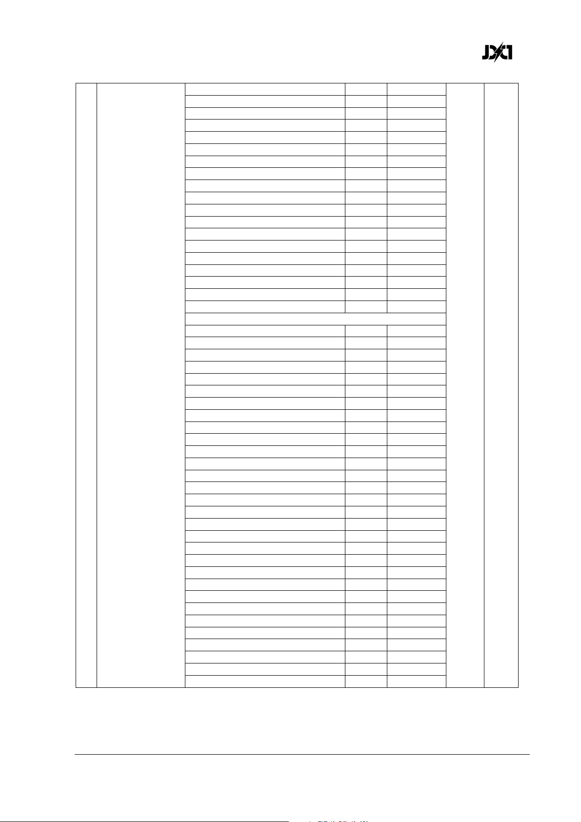
Position feedback on* 40-44 15.7-17.3%
Position feedback off* 45-49 17.7-19.2%
Barndoor on* 50-54 19.6-21.2%
Barndoor off* 55-59 21.6-23.1%
No function 60-61 23.5-23.9%
Tilt power on* 62-63 24.3-24.7%
Tilt power off* 64-65 25.1-25.5%
Tilt reset on* 66-67 25.9-26.3%
Tilt reset off* 68-69 26.7-27.1%
Normal tilt control* 70-74 27.5-29.0%
Inverse tilt control* 75-79 29.4-31.0%
Normal pixel numbering, plates 1+2 80-84 31.4-32.9%
Inverse pixel numbering, plates 1+2 85-89 33.3-34.9%
Normal pixel numbering, 2nd plate 90-94 35.3-36.9%
Inverse pixel numbering, 2nd plate 95-99 37.3-38.8%
Linear dimming curve 100-101 39.2-39.6%
Soft dimming curve 102-103 40.0-40.4%
Extra-soft dimming curve 104-105 40.8-41.2%
No function 106-120 41.6-47.1%
PWM frequency (hold value for >3 seconds):
582 Hz 121-122 47.5-47.8%
583 Hz 123-124 48.2-48.6%
584 Hz 125-126 49.0-49.4%
585 Hz 127-128 49.8-50.2%
Special / Control
7
(continued)
586 Hz 129-130 50.6-51.0%
587 Hz 131-132 51.4-51.8%
588 Hz 133-134 52.2-52.5%
589 Hz 135-136 52.9-53.3%
590 Hz 137-138 53.7-54.1%
591 Hz 139-140 54.5-54.9%
592 Hz 141-142 55.3-55.7%
593 Hz 143-144 56.1-56.5%
594 Hz 145-146 56.9-57.3%
595 Hz 147-148 57.6-58.0%
596 Hz 149-150 58.4-58.8%
597 Hz 151-152 59.2-59.6%
598 Hz 153-154 60.0-60.4%
599 Hz 155-156 60.8-61.2%
600 Hz 157-158 61.6-62.0%
601 Hz 159-160 62.4-62.7%
602 Hz 161-162 63.1-63.5%
603 Hz 163-164 63.9-64.3%
604 Hz 165-166 64.7-65.1%
605 Hz 167-168 65.5-65.9%
606 Hz 169-170 66.3-66.7%
607 Hz 171-172 67.1-67.5%
608 Hz 173-174 67.8-68.2%
609 Hz 175-176 68.6-69.0%
610 Hz 177-178 69.4-69.8%
611 Hz 179-180 70.2-70.6%
JDC1 User Manual Rev. 3.0 35
Page 36
www.glp.de
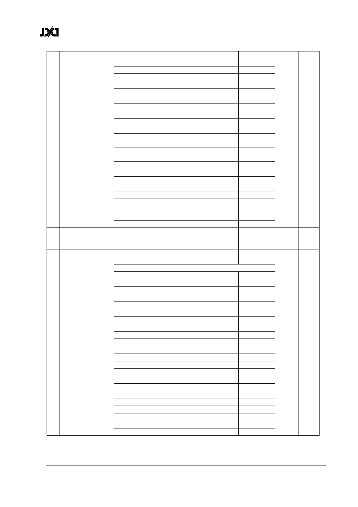
612 Hz 181-182 71.0-71.4%
613 Hz 183-184 71.8-72.2%
614 Hz 185-186 72.5-72.9%
615 Hz 187-188 73.3-73.7%
616 Hz 189-190 74.1-74.5%
617 Hz 191-192 74.9-75.3%
618 Hz 193-194 75.6-76.1%
1200 Hz 195-197 76.5-77.3%
2400 Hz 198-200 77.6-78.4%
Fan mode = Auto 201-204 78.8-80.0%
Fan mode = HIgh 205-209 80.4-82.0%
Special /Control
7
(continued)
8 Plate Intensity Intensity 0-100% 0-255 0-100% 0 Fade
9 Plate Flash
Duration
10 Plate Flash Rate 0.289-16.67 Hz 0-255 0-100% 255 Fade
11 Plate Shutter
Percentage flash mode (hold for
>0.5 sec.) 210-214 82.5-84.0%
Normal flash mode (hold for >0.5
sec.) 215-219 84.5-85.0%
Dimmer flash mode on* 220-224 86.0-87.5%
Dimmer flash mode off* 225-229 88.0-90.0%
FX color priority = Beam* 230-233 90.5-91.4%
FX color priority = Mixed* 234-236 91.8-92.5%
FX color priority = Plate* 237-239 92.9-93.7%
Aggressive flash mode (hold for
>0.5 sec.) 240-244 94.1-95.7%
No function 245-247 96.1-96.9%
Reset (hold value for >5 sec.) 248-255 97.3-100%
7-650 ms 0-255 0-100% 255 Fade
No function 0 0% 0 Snap
Plate Shutter effects and FX patterns offset:
10° 1 0.4%
20° 2 0.8%
30° 3 1.2%
40° 4 1.6%
50° 5 2.0%
60° 6 2.4%
70° 7 2.8%
80° 8 3.1%
90° 9 3.5%
100° 10 3.9%
110° 11 4.3%
120° 12 4.7%
130° 13 5.1%
140° 14 5.5%
150° 15 5.9%
160° 16 6.3%
170° 17 6.7%
180° 18 7.1%
190° 19 7.5%
200° 20 7.8%
210° 21 8.2%
220° 22 8.6%
36 JDC1
User Manual Rev. 3.0
Page 37
German Light Products®
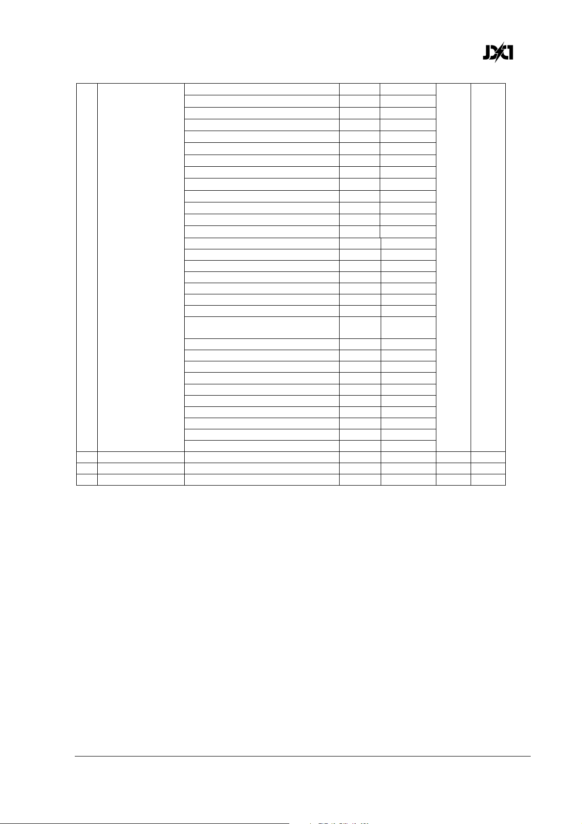
240° 24 9.4%
250° 25 9.8%
260° 26 10.2%
270° 27 10.6%
280° 28 11.0%
290° 29 11.4%
300° 30 11.8%
310° 31 12.2%
320° 32 12.6%
330° 33 12.9%
340° 34 13.3%
350° 35 13.7%
360° 36 14.1%
Ramp up (fade on, snap off) 37-40 14.5-15.5%
Plate Shutter
11
(continued)
12 Plates Red Plates red intensity 0-100% 0-255 0-100% 255 Fade
13 Plates Green Plates green intensity 0-100% 0-255 0-100% 255 Fade
14 Plates Blue Plates blue intensity 0-100% 0-255 0-100% 255 Fade
Ramp up, random 41-44 16.0-17.0%
Ramp down 45-48 17.5-18.5%
Ramp down, random 49-52 19.0-20.0%
Ramp up / down 53-56 20.5-21.5%
Ramp up / down, random 57-60 22.0-23.0%
Random white beam 61-64 23.5-24.5%
Random single pixel in white
beam 65-68 25.0-26.0%
Lightning 69-72 26.5-27.5%
Spikes (flash over low light) 73-76 28.0-29.0%
No function 77-179 29.5-70.0%
Double flash 180-191 70.6-74.9%
Double flash, random 192-203 75.3-79.6%
Triple flash 204-215 80.0-84.3%
Triple flash, random 216-227 84.7-89.0%
Quad flash 228-239 89.4-93.7%
Quad flash, random 240-251 94.1-98.4%
No effect 252-255 98.5-100%
JDC1 User Manual Rev. 3.0 37
Page 38
www.glp.de
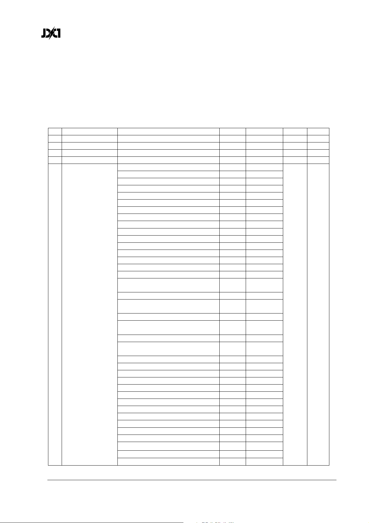
DMX Mode 2 (Normal), 23 DMX Channels
Tilt, Beam shutter, special/control, Plates shutter, Plates grouped RGB, Plate and Beam
FX, Plates background grouped RGB
DMX
Channel Command
1 Coarse Tilt (MSB) 0-185° 0-255 0-100% 127 Fade
2 Fine Tilt (LSB) Coarse tilt + 0-1.2° 0-255 0-100% 127 Fade
3 Beam Intensity Intensity 0-100% 0-255 0-100% 0 Fade
4 Beam Duration Flash duration 7-650 ms 0-255 0-100% 255 Fade
5 Beam Rate Flash rate 0.289-16.67 Hz 0-255 0-100% 255 Fade
No effect 0-36 0-14.0% 0 Snap
Ramp up (= fade on, snap off) 37-40 14.5-15.5%
Ramp up random 41-44 16.0-17.0%
Ramp down 45-48 17.5-18.5%
Ramp down random 49-52 19.0-20.0%
Ramp up down 53-56 20.5-21.5%
Ramp up down random 57-60 22.0-23.0%
Random white beam 61-64 23.5-24.5%
Random single pixel of white beam 65-68 25.0-26.0%
Lightning 69-72 26.5-27.5%
Spikes (flash over low light) 73-76 28.0-29.0%
White beam, left to right 77-80 30.0-31.5%
White beam, left to right, random 81-84 32.0-33.0%
White beam, right to left 85-88 33.5-34.5%
White beam, right to left, random 89-92 35.0-36.0%
White beam, left to right, bounce 93-96 36.5-37.5%
White beam, left to right, bounce,
random 97-100 38.0-39.0%
White beam, right to left, bounce 101-104 39.5-40.5%
White beam, right to left, bounce,
6 Beam Shutter
random 105-108 41.0-42.5%
Zig, 6 steps, outer to center pixels 109-112 43.0-43.5%
Zig, 6 steps, outer to center pixels
random 113-116 44.0-45.5%
Zag, 6 steps, center to outer pixels 117-120 46.0-47.0%
Zag, 6 steps, center to outer pixels,
random 121-124 47.5-48.5%
Zigzag, 10 steps 125-128 49.0-50.0%
Zigzag, 10 steps, random 129-132 50.5-52.0%
No function 133-179 52.5-70.0%
Double flash 180-183 70.6-71.8%
Double flash, random 184-187 72.2-73.3%
Double flash, b-c (beam-color) 188-191 73.7-74.9%
Double flash, b-c, random 192-195 75.3-76.5%
Double flash, c-b (color-beam) 196-199 76.9-78.0%
Double flash, c-b, random 200-203 78.4-79.6%
Triple flash 204-207 80.0-81.2%
Triple flash, random 208-211 81.6-82.7%
Triple flash, beam-color-beam 212-215 83.1-84.3%
Triple flash, b-c-b, random 216-219 84.7-85.9%
Triple flash, c-b-c 220-223 86.3-87.5%
Triple flash, c-b-c, random 224-227 87.8-89.0%
range Percent
Default
DMX Fade
38 JDC1
User Manual Rev. 3.0
Page 39
German Light Products®
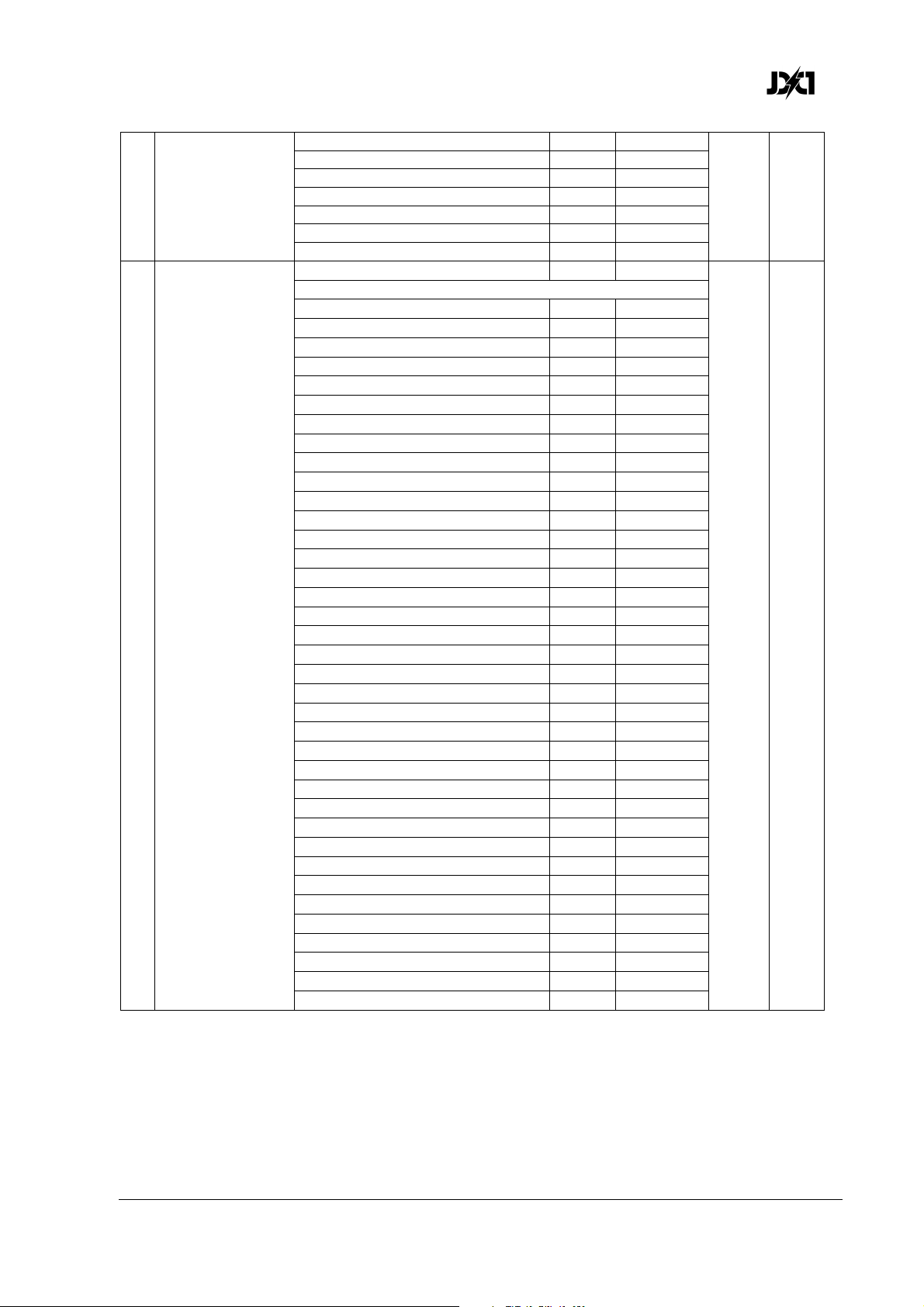
Quad flash 228-231 89.4-90.6%
Quad flash, random 232-235 91.0-92.2%
Beam Shutter
6
(continued)
7 Special / Control
Quad flash, b-c-b-c 236-239 92.5-93.7%
Quad flash, b-c-b-c, random 240-243 94.1-95.3%
Quad flash, c-b-c-b 244-247 95.7-96.9%
Quad flash, c-b-c-b, random 248-251 97.3-98.4%
No function 252-255 98.5-100%
No function 0 0% 0 Snap
Beam Shutter effects and FX patterns offset:
10° 1 0.4%
20° 2 0.8%
30° 3 1.2%
40° 4 1.6%
50° 5 2.0%
60° 6 2.4%
70° 7 2.8%
80° 8 3.1%
90° 9 3.5%
100° 10 3.9%
110° 11 4.3%
120° 12 4.7%
130° 13 5.1%
140° 14 5.5%
150° 15 5.9%
160° 16 6.3%
170° 17 6.7%
180° 18 7.1%
190° 19 7.5%
200° 20 7.8%
210° 21 8.2%
220° 22 8.6%
230° 23 9.0%
240° 24 9.4%
250° 25 9.8%
260° 26 10.2%
270° 27 10.6%
280° 28 11.0%
290° 29 11.4%
300° 30 11.8%
310° 31 12.2%
320° 32 12.6%
330° 33 12.9%
340° 34 13.3%
350° 35 13.7%
360° 36 14.1%
No function 37-39 14.5-15.3%
JDC1 User Manual Rev. 3.0 39
Page 40
www.glp.de
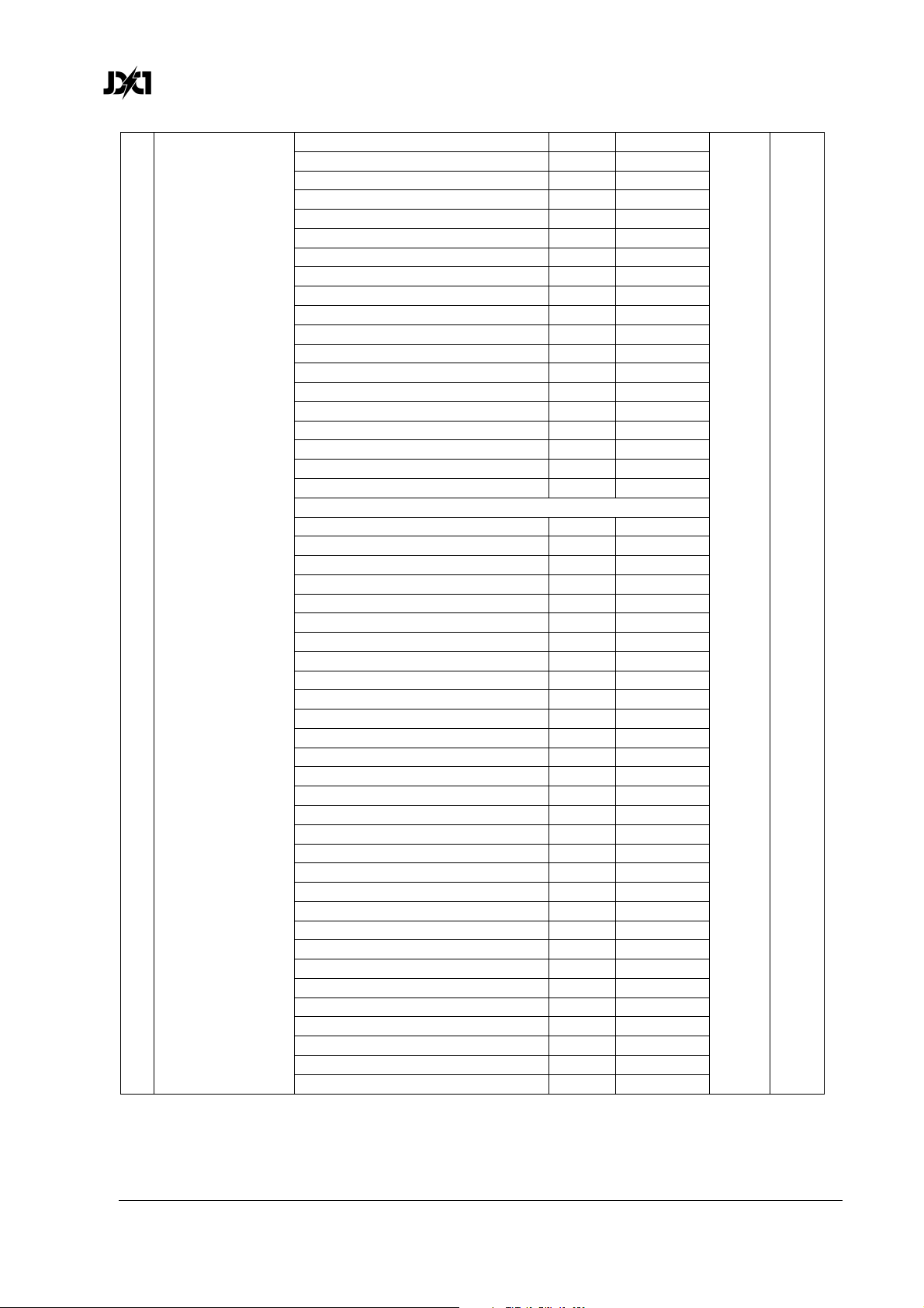
Position feedback on* 40-44 15.7-17.3%
Position feedback off* 45-49 17.7-19.2%
Barndoor on* 50-54 19.6-21.2%
Barndoor off* 55-59 21.6-23.1%
No function 60-61 23.5-23.9%
Tilt power on* 62-63 24.3-24.7%
Tilt power off* 64-65 25.1-25.5%
Tilt reset on* 66-67 25.9-26.3%
Tilt reset off* 68-69 26.7-27.1%
Normal tilt control* 70-74 27.5-29.0%
Inverse tilt control* 75-79 29.4-31.0%
Normal pixel numbering, plates 1+2 80-84 31.4-32.9%
Inverse pixel numbering, plates 1+2 85-89 33.3-34.9%
Normal pixel numbering, 2nd plate 90-94 35.3-36.9%
Inverse pixel numbering, 2nd plate 95-99 37.3-38.8%
Linear dimming curve 100-101 39.2-39.6%
Soft dimming curve 102-103 40.0-40.4%
Extra-soft dimming curve 104-105 40.8-41.2%
No function 106-120 41.6-47.1%
PWM frequency (hold value for >3 seconds):
582 Hz 121-122 47.5-47.8%
583 Hz 123-124 48.2-48.6%
584 Hz 125-126 49.0-49.4%
585 Hz 127-128 49.8-50.2%
Special / Control
7
(continued)
586 Hz 129-130 50.6-51.0%
587 Hz 131-132 51.4-51.8%
588 Hz 133-134 52.2-52.5%
589 Hz 135-136 52.9-53.3%
590 Hz 137-138 53.7-54.1%
591 Hz 139-140 54.5-54.9%
592 Hz 141-142 55.3-55.7%
593 Hz 143-144 56.1-56.5%
594 Hz 145-146 56.9-57.3%
595 Hz 147-148 57.6-58.0%
596 Hz 149-150 58.4-58.8%
597 Hz 151-152 59.2-59.6%
598 Hz 153-154 60.0-60.4%
599 Hz 155-156 60.8-61.2%
600 Hz 157-158 61.6-62.0%
601 Hz 159-160 62.4-62.7%
602 Hz 161-162 63.1-63.5%
603 Hz 163-164 63.9-64.3%
604 Hz 165-166 64.7-65.1%
605 Hz 167-168 65.5-65.9%
606 Hz 169-170 66.3-66.7%
607 Hz 171-172 67.1-67.5%
608 Hz 173-174 67.8-68.2%
609 Hz 175-176 68.6-69.0%
610 Hz 177-178 69.4-69.8%
611 Hz 179-180 70.2-70.6%
40 JDC1
User Manual Rev. 3.0
Page 41
German Light Products®
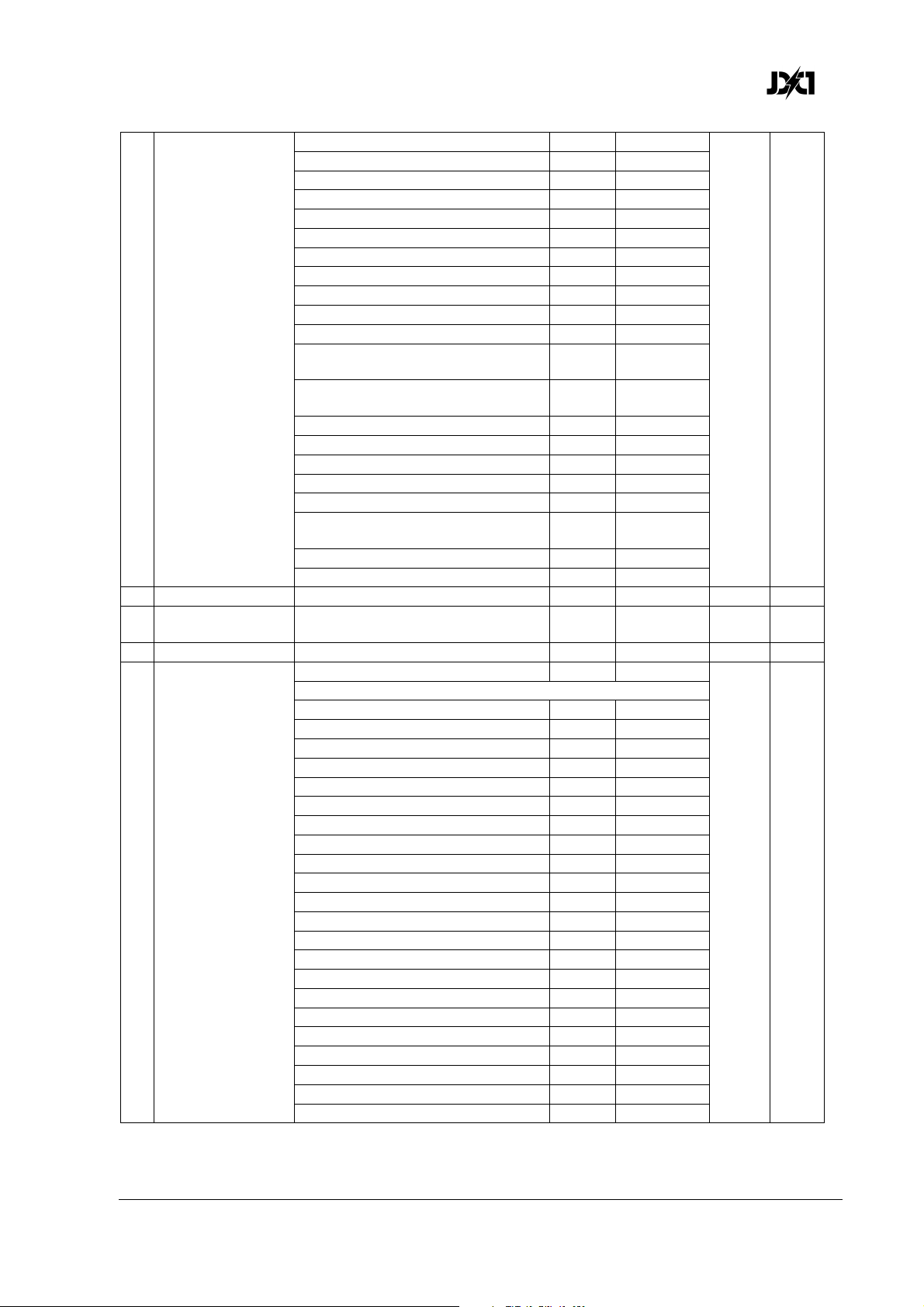
612 Hz 181-182 71.0-71.4%
613 Hz 183-184 71.8-72.2%
614 Hz 185-186 72.5-72.9%
615 Hz 187-188 73.3-73.7%
616 Hz 189-190 74.1-74.5%
617 Hz 191-192 74.9-75.3%
618 Hz 193-194 75.6-76.1%
1200 Hz 195-197 76.5-77.3%
2400 Hz 198-200 77.6-78.4%
Fan mode = Auto 201-204 78.8-80.0%
Fan mode = HIgh 205-209 80.4-82.0%
Special /Control
7
(continued)
8 Plate Intensity Intensity 0-100% 0-255 0-100% 0 Fade
9 Plate Flash
Duration
10 Plate Flash Rate 0.289-16.67 Hz 0-255 0-100% 255 Fade
11 Plate Shutter
Percentage flash mode (hold for
>0.5 sec.) 210-214 82.5-84.0%
Normal flash mode (hold for >0.5
sec.) 215-219 84.5-85.0%
Dimmer flash mode on* 220-224 86.0-87.5%
Dimmer flash mode off* 225-229 88.0-90.0%
FX color priority = Beam* 230-233 90.5-91.4%
FX color priority = Mixed* 234-236 91.8-92.5%
FX color priority = Plate* 237-239 92.9-93.7%
Aggressive flash mode (hold for
>0.5 sec.) 240-244 94.1-95.7%
No function 245-247 96.1-96.9%
Reset (hold value for >5 sec.) 248-255 97.3-100%
7-650 ms 0-255 0-100% 255 Fade
No function 0 0% 0 Snap
Plate Shutter effects and FX patterns offset:
10° 1 0.4%
20° 2 0.8%
30° 3 1.2%
40° 4 1.6%
50° 5 2.0%
60° 6 2.4%
70° 7 2.8%
80° 8 3.1%
90° 9 3.5%
100° 10 3.9%
110° 11 4.3%
120° 12 4.7%
130° 13 5.1%
140° 14 5.5%
150° 15 5.9%
160° 16 6.3%
170° 17 6.7%
180° 18 7.1%
190° 19 7.5%
200° 20 7.8%
210° 21 8.2%
220° 22 8.6%
JDC1 User Manual Rev. 3.0 41
Page 42
www.glp.de
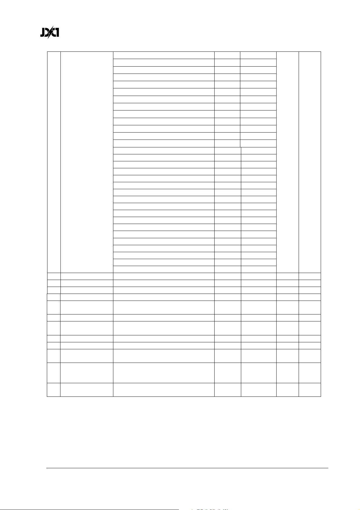
240° 24 9.4%
250° 25 9.8%
260° 26 10.2%
270° 27 10.6%
280° 28 11.0%
290° 29 11.4%
300° 30 11.8%
310° 31 12.2%
320° 32 12.6%
330° 33 12.9%
340° 34 13.3%
350° 35 13.7%
360° 36 14.1%
Ramp up (fade on, snap off) 37-40 14.5-15.5%
Plate Shutter
11
(continued)
12 Plates Red Plates red intensity 0-100% 0-255 0-100% 255 Fade
13 Plates Green Plates green intensity 0-100% 0-255 0-100% 255 Fade
14 Plates Blue Plates blue intensity 0-100% 0-255 0-100% 255 Fade
15 FX Crossfade Crossfade duration snap - slow 0-255 0-100% 0 Fade
Plate FX
16
Movement
17 Plate FX Select Plate FX pattern select 0-255 0-100% 0 Snap
Beam FX
18
Movement
19 Beam FX Select Beam FX pattern select 0-255 0-100% 0 Snap
20 Plates Master FX background intensity 0-100% 0-255 0-100% 0 Fade
Plates
21
Background Red
Plates
22
Background
Green
Plates
23
Background Blue
Ramp up, random 41-44 16.0-17.0%
Ramp down 45-48 17.5-18.5%
Ramp down, random 49-52 19.0-20.0%
Ramp up / down 53-56 20.5-21.5%
Ramp up / down, random 57-60 22.0-23.0%
Random white beam 61-64 23.5-24.5%
Random single pixel in white beam 65-68 25.0-26.0%
Lightning 69-72 26.5-27.5%
Spikes (flash over low light) 73-76 28.0-29.0%
No function 77-179 29.5-70.0%
Double flash 180-191 70.6-74.9%
Double flash, random 192-203 75.3-79.6%
Triple flash 204-215 80.0-84.3%
Triple flash, random 216-227 84.7-89.0%
Quad flash 228-239 89.4-93.7%
Quad flash, random 240-251 94.1-98.4%
No effect 252-255 98.5-100%
Plate FX movement speed slow - fast 0-255 0-100% 0 Snap
Beam FX movement speed slow fast
FX background intensity red
0-100%
FX background intensity green
0-100% 0-255 0-100% 255 Fade
FX background intensity blue
0-100%
0-255 0-100% 0 Snap
0-255 0-100% 255 Fade
0-255 0-100% 255 Fade
42 JDC1
User Manual Rev. 3.0
Page 43
German Light Products®
DMX Mode 3 (SPix), 68 DMX Channels
Tilt, Beam shutter, special/control, Plates shutter, Plates grouped RGB, Plate and Beam
FX, Plate background individual pixel RGB, Beam individual pixel intensity
DMX
Channel Command
1 Coarse Tilt (MSB) 0-185° 0-255 0-100% 127 Fade
2 Fine Tilt (LSB) Coarse tilt + 0-1.2° 0-255 0-100% 127 Fade
3 Beam Intensity Intensity 0-100% 0-255 0-100% 0 Fade
4 Beam Duration Flash duration 7-650 ms 0-255 0-100% 255 Fade
5 Beam Rate Flash rate 0.289-16.67 Hz 0-255 0-100% 255 Fade
No effect 0-36 0-14.0% 0 Snap
Ramp up (= fade on, snap off) 37-40 14.5-15.5%
Ramp up random 41-44 16.0-17.0%
Ramp down 45-48 17.5-18.5%
Ramp down random 49-52 19.0-20.0%
Ramp up down 53-56 20.5-21.5%
Ramp up down random 57-60 22.0-23.0%
Random white beam 61-64 23.5-24.5%
Random single pixel of white beam 65-68 25.0-26.0%
Lightning 69-72 26.5-27.5%
Spikes (flash over low light) 73-76 28.0-29.0%
White beam, left to right 77-80 30.0-31.5%
White beam, left to right, random 81-84 32.0-33.0%
White beam, right to left 85-88 33.5-34.5%
White beam, right to left, random 89-92 35.0-36.0%
White beam, left to right, bounce 93-96 36.5-37.5%
White beam, left to right, bounce,
random 97-100 38.0-39.0%
White beam, right to left, bounce 101-104 39.5-40.5%
White beam, right to left, bounce,
6 Beam Shutter
random 105-108 41.0-42.5%
Zig, 6 steps, outer to center pixels 109-112 43.0-43.5%
Zig, 6 steps, outer to center pixels
random 113-116 44.0-45.5%
Zag, 6 steps, center to outer pixels 117-120 46.0-47.0%
Zag, 6 steps, center to outer pixels,
random 121-124 47.5-48.5%
Zigzag, 10 steps 125-128 49.0-50.0%
Zigzag, 10 steps, random 129-132 50.5-52.0%
No function 133-179 52.5-70.0%
Double flash 180-183 70.6-71.8%
Double flash, random 184-187 72.2-73.3%
Double flash, b-c (beam-color) 188-191 73.7-74.9%
Double flash, b-c, random 192-195 75.3-76.5%
Double flash, c-b (color-beam) 196-199 76.9-78.0%
Double flash, c-b, random 200-203 78.4-79.6%
Triple flash 204-207 80.0-81.2%
Triple flash, random 208-211 81.6-82.7%
Triple flash, beam-color-beam 212-215 83.1-84.3%
Triple flash, b-c-b, random 216-219 84.7-85.9%
Triple flash, c-b-c 220-223 86.3-87.5%
Triple flash, c-b-c, random 224-227 87.8-89.0%
range Percent
Default
DMX Fade
JDC1 User Manual Rev. 3.0 43
Page 44
www.glp.de
Quad flash 228-231 89.4-90.6%
Quad flash, random 232-235 91.0-92.2%
Beam Shutter
6
(continued)
7 Special / Control
Quad flash, b-c-b-c 236-239 92.5-93.7%
Quad flash, b-c-b-c, random 240-243 94.1-95.3%
Quad flash, c-b-c-b 244-247 95.7-96.9%
Quad flash, c-b-c-b, random 248-251 97.3-98.4%
No function 252-255 98.5-100%
No function 0 0% 0 Snap
Beam Shutter effects and FX patterns offset:
10° 1 0.4%
20° 2 0.8%
30° 3 1.2%
40° 4 1.6%
50° 5 2.0%
60° 6 2.4%
70° 7 2.8%
80° 8 3.1%
90° 9 3.5%
100° 10 3.9%
110° 11 4.3%
120° 12 4.7%
130° 13 5.1%
140° 14 5.5%
150° 15 5.9%
160° 16 6.3%
170° 17 6.7%
180° 18 7.1%
190° 19 7.5%
200° 20 7.8%
210° 21 8.2%
220° 22 8.6%
230° 23 9.0%
240° 24 9.4%
250° 25 9.8%
260° 26 10.2%
270° 27 10.6%
280° 28 11.0%
290° 29 11.4%
300° 30 11.8%
310° 31 12.2%
320° 32 12.6%
330° 33 12.9%
340° 34 13.3%
350° 35 13.7%
360° 36 14.1%
No function 37-39 14.5-15.3%
44 JDC1
User Manual Rev. 3.0
Page 45
German Light Products®
Position feedback on* 40-44 15.7-17.3%
Position feedback off* 45-49 17.7-19.2%
Barndoor on* 50-54 19.6-21.2%
Barndoor off* 55-59 21.6-23.1%
No function 60-61 23.5-23.9%
Tilt power on* 62-63 24.3-24.7%
Tilt power off* 64-65 25.1-25.5%
Tilt reset on* 66-67 25.9-26.3%
Tilt reset off* 68-69 26.7-27.1%
Normal tilt control* 70-74 27.5-29.0%
Inverse tilt control* 75-79 29.4-31.0%
Normal pixel numbering, plates 1+2 80-84 31.4-32.9%
Inverse pixel numbering, plates 1+2 85-89 33.3-34.9%
Normal pixel numbering, 2nd plate 90-94 35.3-36.9%
Inverse pixel numbering, 2nd plate 95-99 37.3-38.8%
Linear dimming curve 100-101 39.2-39.6%
Soft dimming curve 102-103 40.0-40.4%
Extra-soft dimming curve 104-105 40.8-41.2%
No function 106-120 41.6-47.1%
PWM frequency (hold value for >3 seconds):
582 Hz 121-122 47.5-47.8%
583 Hz 123-124 48.2-48.6%
584 Hz 125-126 49.0-49.4%
585 Hz 127-128 49.8-50.2%
Special / Control
7
(continued)
586 Hz 129-130 50.6-51.0%
587 Hz 131-132 51.4-51.8%
588 Hz 133-134 52.2-52.5%
589 Hz 135-136 52.9-53.3%
590 Hz 137-138 53.7-54.1%
591 Hz 139-140 54.5-54.9%
592 Hz 141-142 55.3-55.7%
593 Hz 143-144 56.1-56.5%
594 Hz 145-146 56.9-57.3%
595 Hz 147-148 57.6-58.0%
596 Hz 149-150 58.4-58.8%
597 Hz 151-152 59.2-59.6%
598 Hz 153-154 60.0-60.4%
599 Hz 155-156 60.8-61.2%
600 Hz 157-158 61.6-62.0%
601 Hz 159-160 62.4-62.7%
602 Hz 161-162 63.1-63.5%
603 Hz 163-164 63.9-64.3%
604 Hz 165-166 64.7-65.1%
605 Hz 167-168 65.5-65.9%
606 Hz 169-170 66.3-66.7%
607 Hz 171-172 67.1-67.5%
608 Hz 173-174 67.8-68.2%
609 Hz 175-176 68.6-69.0%
610 Hz 177-178 69.4-69.8%
611 Hz 179-180 70.2-70.6%
JDC1 User Manual Rev. 3.0 45
Page 46
www.glp.de
612 Hz 181-182 71.0-71.4%
613 Hz 183-184 71.8-72.2%
614 Hz 185-186 72.5-72.9%
615 Hz 187-188 73.3-73.7%
616 Hz 189-190 74.1-74.5%
617 Hz 191-192 74.9-75.3%
618 Hz 193-194 75.6-76.1%
1200 Hz 195-197 76.5-77.3%
2400 Hz 198-200 77.6-78.4%
Fan mode = Auto 201-204 78.8-80.0%
Fan mode = High 205-209 80.4-82.0%
Special /Control
7
(continued)
8 Plate Intensity Intensity 0-100% 0-255 0-100% 0 Fade
9 Plate Flash
Duration
10 Plate Flash Rate 0.289-16.67 Hz 0-255 0-100% 255 Fade
11 Plate Shutter
Percentage flash mode (hold for
>0.5 sec.) 210-214 82.5-84.0%
Normal flash mode (hold for >0.5
sec.) 215-219 84.5-85.0%
Dimmer flash mode on* 220-224 86.0-87.5%
Dimmer flash mode off* 225-229 88.0-90.0%
FX color priority = Beam* 230-233 90.5-91.4%
FX color priority = Mixed* 234-236 91.8-92.5%
FX color priority = Plate* 237-239 92.9-93.7%
Aggressive flash mode (hold for
>0.5 sec.) 240-244 94.1-95.7%
No function 245-247 96.1-96.9%
Reset (hold value for >5 sec.) 248-255 97.3-100%
7-650 ms 0-255 0-100% 255 Fade
No function 0 0% 0 Snap
Plate Shutter effects and FX patterns offset:
10° 1 0.4%
20° 2 0.8%
30° 3 1.2%
40° 4 1.6%
50° 5 2.0%
60° 6 2.4%
70° 7 2.8%
80° 8 3.1%
90° 9 3.5%
100° 10 3.9%
110° 11 4.3%
120° 12 4.7%
130° 13 5.1%
140° 14 5.5%
150° 15 5.9%
160° 16 6.3%
170° 17 6.7%
180° 18 7.1%
190° 19 7.5%
200° 20 7.8%
210° 21 8.2%
220° 22 8.6%
46 JDC1
User Manual Rev. 3.0
Page 47
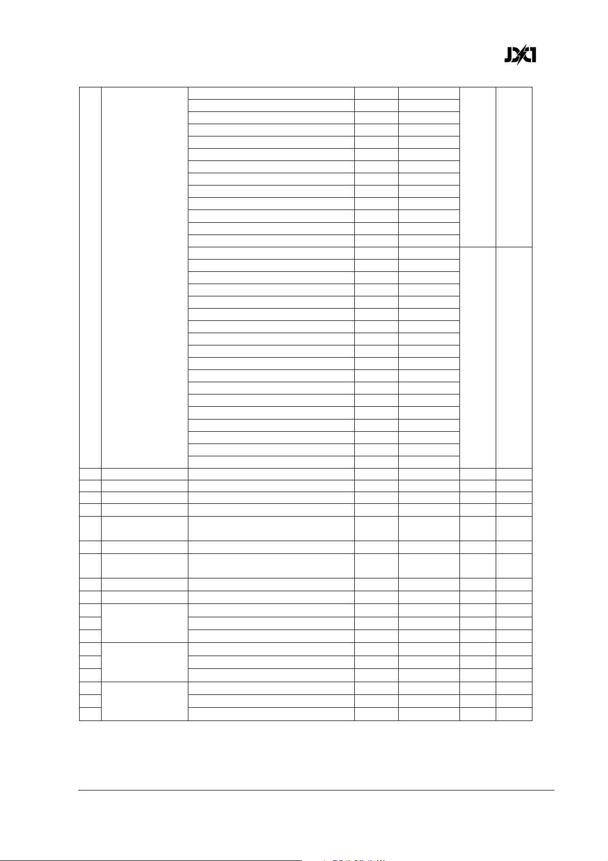
German Light Products®
240° 24 9.4%
250° 25 9.8%
260° 26 10.2%
270° 27 10.6%
280° 28 11.0%
290° 29 11.4%
300° 30 11.8%
310° 31 12.2%
320° 32 12.6%
330° 33 12.9%
340° 34 13.3%
350° 35 13.7%
360° 36 14.1%
Ramp up (fade on, snap off) 37-40 14.5-15.5%
Plate Shutter
11
(continued)
12 Plates Red Plates red intensity 0-100% 0-255 0-100% 255 Fade
13 Plates Green Plates green intensity 0-100% 0-255 0-100% 255 Fade
14 Plates Blue Plates blue intensity 0-100% 0-255 0-100% 255 Fade
15 FX Crossfade Crossfade duration snap - slow 0-255 0-100% 0 Fade
Plate FX
16
Movement
17 Plate FX Select Plate FX pattern select 0-255 0-100% 0 Snap
Beam FX
18
Movement
19 Beam FX Select Beam FX pattern select 0-255 0-100% 0 Snap
20 Plate Master FX background intensity 0-100% 0-255 0-100% 0 Fade
21
Plate Background
22 Green 0-100% 0-255 255 Fade
Pixel 1
23 Blue 0-100% 0-255 255 Fade
24
Plate Background
25 Green 0-100% 0-255 255 Fade
Pixel 2
26 Blue 0-100% 0-255 255 Fade
27
Plate Background
28 Green 0-100% 0-255 255 Fade
Pixel 3
29 Blue 0-100% 0-255 255 Fade
Ramp up, random 41-44 16.0-17.0%
Ramp down 45-48 17.5-18.5%
Ramp down, random 49-52 19.0-20.0%
Ramp up / down 53-56 20.5-21.5%
Ramp up / down, random 57-60 22.0-23.0%
Random white beam 61-64 23.5-24.5%
Random single pixel in white beam 65-68 25.0-26.0%
Lightning 69-72 26.5-27.5%
Spikes (flash over low light) 73-76 28.0-29.0%
No function 77-179 29.5-70.0%
Double flash 180-191 70.6-74.9%
Double flash, random 192-203 75.3-79.6%
Triple flash 204-215 80.0-84.3%
Triple flash, random 216-227 84.7-89.0%
Quad flash 228-239 89.4-93.7%
Quad flash, random 240-251 94.1-98.4%
No effect 252-255 98.5-100%
Plate FX movement speed slow fast
Beam FX movement speed slow fast
Red 0-100% 0-255 255 Fade
Red 0-100% 0-255 255 Fade
Red 0-100% 0-255 255 Fade
0-255 0-100% 0 Fade
0-255 0-100% 0 Fade
JDC1 User Manual Rev. 3.0 47
Page 48
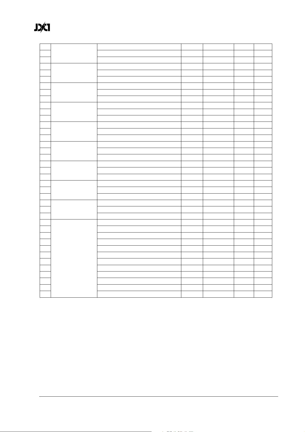
www.glp.de
30
Plate Background
31 Green 0-100% 0-255 255 Fade
Pixel 4
32 Blue 0-100% 0-255 255 Fade
33
Plate Background
34 Green 0-100% 0-255 255 Fade
Pixel 5
35 Blue 0-100% 0-255 255 Fade
36
Plate Background
37 Green 0-100% 0-255 255 Fade
Pixel 6
38 Blue 0-100% 0-255 255 Fade
39
Plate Background
40 Green 0-100% 0-255 255 Fade
Pixel 7
41 Blue 0-100% 0-255 255 Fade
42
Plate Background
43 Green 0-100% 0-255 255 Fade
Pixel 8
44 Blue 0-100% 0-255 255 Fade
45
Plate Background
46 Green 0-100% 0-255 255 Fade
Pixel 9
47 Blue 0-100% 0-255 255 Fade
48
Plate Background
49 Green 0-100% 0-255 255 Fade
Pixel 10
50 Blue 0-100% 0-255 255 Fade
51
Plate Background
52 Green 0-100% 0-255 255 Fade
Pixel 11
53 Blue 0-100% 0-255 255 Fade
54
Plate Background
55 Green 0-100% 0-255 255 Fade
Pixel 12
56 Blue 0-100% 0-255 255 Fade
57
58 Pixel 2 0-100% 0-255 0 Fade
59 Pixel 3 0-100% 0-255 0 Fade
60 Pixel 4 0-100% 0-255 0 Fade
61 Pixel 5 0-100% 0-255 0 Fade
62 Pixel 6 0-100% 0-255 0 Fade
Beam Pixels
Intensity
63 Pixel 7 0-100% 0-255 0 Fade
64 Pixel 8 0-100% 0-255 0 Fade
65 Pixel 9 0-100% 0-255 0 Fade
66 Pixel 10 0-100% 0-255 0 Fade
67 Pixel 11 0-100% 0-255 0 Fade
68 Pixel 12 0-100% 0-255 0 Fade
Red 0-100% 0-255 255 Fade
Red 0-100% 0-255 255 Fade
Red 0-100% 0-255 255 Fade
Red 0-100% 0-255 255 Fade
Red 0-100% 0-255 255 Fade
Red 0-100% 0-255 255 Fade
Red 0-100% 0-255 255 Fade
Red 0-100% 0-255 255 Fade
Red 0-100% 0-255 255 Fade
Pixel 1 0-100% 0-255 0 Fade
48 JDC1
User Manual Rev. 3.0
Page 49
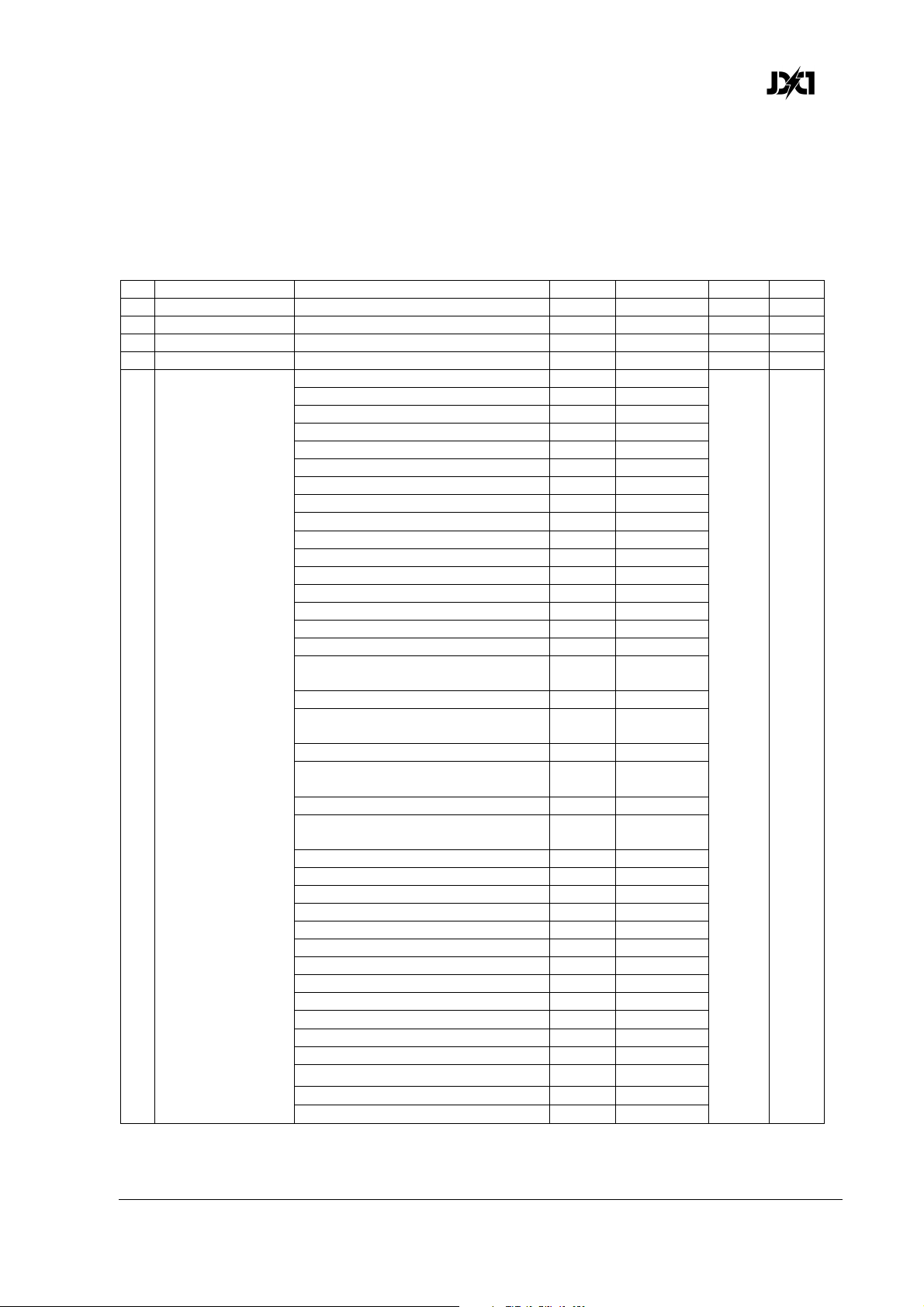
German Light Products®
DMX Mode 4 (SPix Pro), 62 DMX Channels
Tilt, Beam shutter, special/control, Plates shutter, Plates grouped RGB, Plate individual
pixel RGB, Beam individual pixel intensity
DMX
Channel Command
1 Coarse Tilt (MSB) 0-185° 0-255 0-100% 127 Fade
2 Fine Tilt (LSB) Coarse tilt + 0-1.2° 0-255 0-100% 127 Fade
3 Beam Intensity Intensity 0-100% 0-255 0-100% 0 Fade
4 Beam Duration Flash duration 7-650 ms 0-255 0-100% 255 Fade
5 Beam Rate Flash rate 0.289-16.67 Hz 0-255 0-100% 255 Fade
No effect 0-36 0-14.0% 0 Snap
Ramp up (= fade on, snap off) 37-40 14.5-15.5%
Ramp up random 41-44 16.0-17.0%
Ramp down 45-48 17.5-18.5%
Ramp down random 49-52 19.0-20.0%
Ramp up down 53-56 20.5-21.5%
Ramp up down random 57-60 22.0-23.0%
Random white beam 61-64 23.5-24.5%
Random single pixel of white beam 65-68 25.0-26.0%
Lightning 69-72 26.5-27.5%
Spikes (flash over low light) 73-76 28.0-29.0%
White beam, left to right 77-80 30.0-31.5%
White beam, left to right, random 81-84 32.0-33.0%
White beam, right to left 85-88 33.5-34.5%
White beam, right to left, random 89-92 35.0-36.0%
White beam, left to right, bounce 93-96 36.5-37.5%
White beam, left to right, bounce,
random 97-100 38.0-39.0%
White beam, right to left, bounce 101-104 39.5-40.5%
White beam, right to left, bounce,
6 Beam Shutter
random 105-108 41.0-42.5%
Zig, 6 steps, outer to center pixels 109-112 43.0-43.5%
Zig, 6 steps, outer to center pixels
random 113-116 44.0-45.5%
Zag, 6 steps, center to outer pixels 117-120 46.0-47.0%
Zag, 6 steps, center to outer pixels,
random 121-124 47.5-48.5%
Zigzag, 10 steps 125-128 49.0-50.0%
Zigzag, 10 steps, random 129-132 50.5-52.0%
No function 133-179 52.5-70.0%
Double flash 180-183 70.6-71.8%
Double flash, random 184-187 72.2-73.3%
Double flash, b-c (beam-color) 188-191 73.7-74.9%
Double flash, b-c, random 192-195 75.3-76.5%
Double flash, c-b (color-beam) 196-199 76.9-78.0%
Double flash, c-b, random 200-203 78.4-79.6%
Triple flash 204-207 80.0-81.2%
Triple flash, random 208-211 81.6-82.7%
Triple flash, beam-color-beam 212-215 83.1-84.3%
Triple flash, b-c-b, random 216-219 84.7-85.9%
Triple flash, c-b-c 220-223 86.3-87.5%
Triple flash, c-b-c, random 224-227 87.8-89.0%
range Percent
Default
DMX Fade
JDC1 User Manual Rev. 3.0 49
Page 50
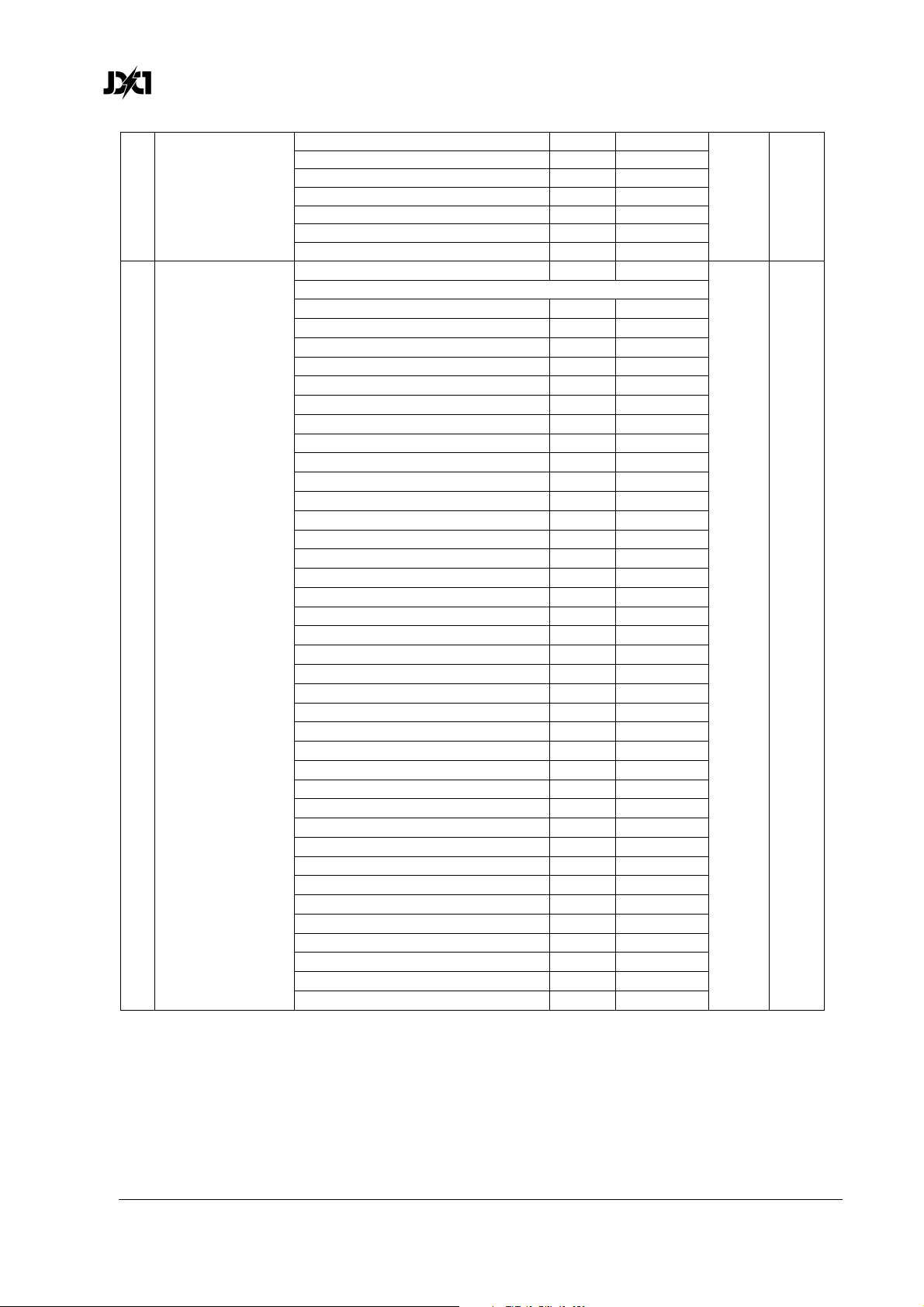
www.glp.de
Quad flash 228-231 89.4-90.6%
Quad flash, random 232-235 91.0-92.2%
Beam Shutter
6
(continued)
7 Special / Control
Quad flash, b-c-b-c 236-239 92.5-93.7%
Quad flash, b-c-b-c, random 240-243 94.1-95.3%
Quad flash, c-b-c-b 244-247 95.7-96.9%
Quad flash, c-b-c-b, random 248-251 97.3-98.4%
No function 252-255 98.5-100%
No function 0 0% 0 Snap
Beam Shutter effects and FX patterns offset:
10° 1 0.4%
20° 2 0.8%
30° 3 1.2%
40° 4 1.6%
50° 5 2.0%
60° 6 2.4%
70° 7 2.8%
80° 8 3.1%
90° 9 3.5%
100° 10 3.9%
110° 11 4.3%
120° 12 4.7%
130° 13 5.1%
140° 14 5.5%
150° 15 5.9%
160° 16 6.3%
170° 17 6.7%
180° 18 7.1%
190° 19 7.5%
200° 20 7.8%
210° 21 8.2%
220° 22 8.6%
230° 23 9.0%
240° 24 9.4%
250° 25 9.8%
260° 26 10.2%
270° 27 10.6%
280° 28 11.0%
290° 29 11.4%
300° 30 11.8%
310° 31 12.2%
320° 32 12.6%
330° 33 12.9%
340° 34 13.3%
350° 35 13.7%
360° 36 14.1%
No function 37-39 14.5-15.3%
50 JDC1
User Manual Rev. 3.0
Page 51
German Light Products®
Position feedback on* 40-44 15.7-17.3%
Position feedback off* 45-49 17.7-19.2%
Barndoor on* 50-54 19.6-21.2%
Barndoor off* 55-59 21.6-23.1%
No function 60-61 23.5-23.9%
Tilt power on* 62-63 24.3-24.7%
Tilt power off* 64-65 25.1-25.5%
Tilt reset on* 66-67 25.9-26.3%
Tilt reset off* 68-69 26.7-27.1%
Normal tilt control* 70-74 27.5-29.0%
Inverse tilt control* 75-79 29.4-31.0%
Normal pixel numbering, plates 1+2 80-84 31.4-32.9%
Inverse pixel numbering, plates 1+2 85-89 33.3-34.9%
Normal pixel numbering, 2nd plate 90-94 35.3-36.9%
Inverse pixel numbering, 2nd plate 95-99 37.3-38.8%
Linear dimming curve 100-101 39.2-39.6%
Soft dimming curve 102-103 40.0-40.4%
Extra-soft dimming curve 104-105 40.8-41.2%
No function 106-120 41.6-47.1%
PWM frequency (hold value for >3 seconds):
582 Hz 121-122 47.5-47.8%
583 Hz 123-124 48.2-48.6%
584 Hz 125-126 49.0-49.4%
585 Hz 127-128 49.8-50.2%
Special / Control
7
(continued)
586 Hz 129-130 50.6-51.0%
587 Hz 131-132 51.4-51.8%
588 Hz 133-134 52.2-52.5%
589 Hz 135-136 52.9-53.3%
590 Hz 137-138 53.7-54.1%
591 Hz 139-140 54.5-54.9%
592 Hz 141-142 55.3-55.7%
593 Hz 143-144 56.1-56.5%
594 Hz 145-146 56.9-57.3%
595 Hz 147-148 57.6-58.0%
596 Hz 149-150 58.4-58.8%
597 Hz 151-152 59.2-59.6%
598 Hz 153-154 60.0-60.4%
599 Hz 155-156 60.8-61.2%
600 Hz 157-158 61.6-62.0%
601 Hz 159-160 62.4-62.7%
602 Hz 161-162 63.1-63.5%
603 Hz 163-164 63.9-64.3%
604 Hz 165-166 64.7-65.1%
605 Hz 167-168 65.5-65.9%
606 Hz 169-170 66.3-66.7%
607 Hz 171-172 67.1-67.5%
608 Hz 173-174 67.8-68.2%
609 Hz 175-176 68.6-69.0%
610 Hz 177-178 69.4-69.8%
611 Hz 179-180 70.2-70.6%
JDC1 User Manual Rev. 3.0 51
Page 52
www.glp.de
612 Hz 181-182 71.0-71.4%
613 Hz 183-184 71.8-72.2%
614 Hz 185-186 72.5-72.9%
615 Hz 187-188 73.3-73.7%
616 Hz 189-190 74.1-74.5%
617 Hz 191-192 74.9-75.3%
618 Hz 193-194 75.6-76.1%
1200 Hz 195-197 76.5-77.3%
2400 Hz 198-200 77.6-78.4%
Fan mode = Auto 201-204 78.8-80.0%
Fan mode = High 205-209 80.4-82.0%
Special /Control
7
(continued)
8 Plate Intensity Intensity 0-100% 0-255 0-100% 0 Fade
9 Plate Flash
Duration
10 Plate Flash Rate 0.289-16.67 Hz 0-255 0-100% 255 Fade
11 Plate Shutter
Percentage flash mode (hold for
>0.5 sec.) 210-214 82.5-84.0%
Normal flash mode (hold for >0.5
sec.) 215-219 84.5-85.0%
Dimmer flash mode on* 220-224 86.0-87.5%
Dimmer flash mode off* 225-229 88.0-90.0%
FX color priority = Beam* 230-233 90.5-91.4%
FX color priority = Mixed* 234-236 91.8-92.5%
FX color priority = Plate* 237-239 92.9-93.7%
Aggressive flash mode (hold for
>0.5 sec.) 240-244 94.1-95.7%
No function 245-247 96.1-96.9%
Reset (hold value for >5 sec.) 248-255 97.3-100%
7-650 ms 0-255 0-100% 255 Fade
No function 0 0% 0 Snap
Plate Shutter effects and FX patterns offset:
10° 1 0.4%
20° 2 0.8%
30° 3 1.2%
40° 4 1.6%
50° 5 2.0%
60° 6 2.4%
70° 7 2.8%
80° 8 3.1%
90° 9 3.5%
100° 10 3.9%
110° 11 4.3%
120° 12 4.7%
130° 13 5.1%
140° 14 5.5%
150° 15 5.9%
160° 16 6.3%
170° 17 6.7%
180° 18 7.1%
190° 19 7.5%
200° 20 7.8%
210° 21 8.2%
220° 22 8.6%
52 JDC1
User Manual Rev. 3.0
Page 53
German Light Products®
240° 24 9.4%
250° 25 9.8%
260° 26 10.2%
270° 27 10.6%
280° 28 11.0%
290° 29 11.4%
300° 30 11.8%
310° 31 12.2%
320° 32 12.6%
330° 33 12.9%
340° 34 13.3%
350° 35 13.7%
360° 36 14.1%
Ramp up (fade on, snap off) 37-40 14.5-15.5%
Plate Shutter
11
(continued)
12 Plates Red Both plates red intensity 0-100% 0-255 0-100% 255 Fade
13 Plates Green Both plates green intensity 0-100% 0-255 0-100% 255 Fade
14 Plates Blue Both plates blue intensity 0-100% 0-255 0-100% 255 Fade
15
Plate Pixel 1
16 Green intensity 0-100% 0-100% 0-255 0 Fade
17 Blue intensity 0-100% 0-100% 0-255 0 Fade
18
Plate Pixel 2
19 Green intensity 0-100% 0-100% 0-255 0 Fade
20 Blue intensity 0-100% 0-100% 0-255 0 Fade
21
Plate Pixel 3
22 Green intensity 0-100% 0-100% 0-255 0 Fade
23 Blue intensity 0-100% 0-100% 0-255 0 Fade
24
25 Green intensity 0-100% 0-100% 0-255 0 Fade
Plate Pixel 4
26 Blue intensity 0-100% 0-100% 0-255 0 Fade
27
Plate Pixel 5
28 Green intensity 0-100% 0-100% 0-255 0 Fade
29 Blue intensity 0-100% 0-100% 0-255 0 Fade
30
31 Green intensity 0-100% 0-100% 0-255 0 Fade
Plate Pixel 6
32 Blue intensity 0-100% 0-100% 0-255 0 Fade
Ramp up, random 41-44 16.0-17.0%
Ramp down 45-48 17.5-18.5%
Ramp down, random 49-52 19.0-20.0%
Ramp up / down 53-56 20.5-21.5%
Ramp up / down, random 57-60 22.0-23.0%
Random white beam 61-64 23.5-24.5%
Random single pixel of white beam 65-68 25.0-26.0%
Lightning 69-72 26.5-27.5%
Spikes (flash over low light) 73-76 28.0-29.0%
No function 77-179 29.5-70.0%
Double flash 180-191 70.6-74.9%
Double flash, random 192-203 75.3-79.6%
Triple flash 204-215 80.0-84.3%
Triple flash, random 216-227 84.7-89.0%
Quad flash 228-239 89.4-93.7%
Quad flash, random 240-251 94.1-98.4%
No effect 252-255 98.5-100%
Red intensity 0-100% 0-100% 0-255 0 Fade
Red intensity 0-100% 0-100% 0-255 0 Fade
Red intensity 0-100% 0-100% 0-255 0 Fade
Red intensity 0-100% 0-100% 0-255 0 Fade
Red intensity 0-100% 0-100% 0-255 0 Fade
Red intensity 0-100% 0-100% 0-255 0 Fade
JDC1 User Manual Rev. 3.0 53
Page 54
www.glp.de
33
Plate Pixel 7
34 Green intensity 0-100% 0-100% 0-255 0 Fade
35 Blue intensity 0-100% 0-100% 0-255 0 Fade
36
Plate Pixel 8
37 Green intensity 0-100% 0-100% 0-255 0 Fade
38 Blue intensity 0-100% 0-100% 0-255 0 Fade
39
Plate Pixel 9
40 Green intensity 0-100% 0-100% 0-255 0 Fade
41 Blue intensity 0-100% 0-100% 0-255 0 Fade
42
Plate Pixel 10
43 Green intensity 0-100% 0-100% 0-255 0 Fade
44 Blue intensity 0-100% 0-100% 0-255 0 Fade
45
Plate Pixel 11
46 Green intensity 0-100% 0-100% 0-255 0 Fade
47 Blue intensity 0-100% 0-100% 0-255 0 Fade
48
Plate Pixel 12
49 Green intensity 0-100% 0-100% 0-255 0 Fade
50 Blue intensity 0-100% 0-100% 0-255 0 Fade
51
52 Pixel 2 intensity 0-100% 0-100% 0-255 0 Fade
53 Pixel 3 intensity 0-100% 0-100% 0-255 0 Fade
54 Pixel 4 intensity 0-100% 0-100% 0-255 0 Fade
55 Pixel 5 intensity 0-100% 0-100% 0-255 0 Fade
56 Pixel 6 intensity 0-100% 0-100% 0-255 0 Fade
Beam Pixels
57 Pixel 7 intensity 0-100% 0-100% 0-255 0 Fade
58 Pixel 8 intensity 0-100% 0-100% 0-255 0 Fade
59 Pixel 9 intensity 0-100% 0-100% 0-255 0 Fade
60 Pixel 10 intensity 0-100% 0-100% 0-255 0 Fade
61 Pixel 11 intensity 0-100% 0-100% 0-255 0 Fade
62 Pixel 12 intensity 0-100% 0-100% 0-255 0 Fade
Red intensity 0-100% 0-100% 0-255 0 Fade
Red intensity 0-100% 0-100% 0-255 0 Fade
Red intensity 0-100% 0-100% 0-255 0 Fade
Red intensity 0-100% 0-100% 0-255 0 Fade
Red intensity 0-100% 0-100% 0-255 0 Fade
Red intensity 0-100% 0-100% 0-255 0 Fade
Pixel 1 intensity 0-100% 0-100% 0-255 0 Fade
54 JDC1
User Manual Rev. 3.0
Page 55
German Light Products®
DMX Mode 5 (1Pix Pro), 17 DMX Channels
Tilt, Beam shutter, special/control, Plates shutter, Plates grouped RGB, Plates
background grouped RGB
DMX
Channel Command
1 Coarse Tilt (MSB) 0-185° 0-255 0-100% 127 Fade
2 Fine Tilt (LSB) Coarse tilt + 0-1.2° 0-255 0-100% 127 Fade
3 Beam Intensity Intensity 0-100% 0-255 0-100% 0 Fade
4 Beam Duration Flash duration 7-650 ms 0-255 0-100% 255 Fade
5 Beam Rate Flash rate 0.289-16.67 Hz 0-255 0-100% 255 Fade
No effect 0-36 0-14.0% 0 Snap
Ramp up (= fade on, snap off) 37-40 14.5-15.5%
Ramp up random 41-44 16.0-17.0%
Ramp down 45-48 17.5-18.5%
Ramp down random 49-52 19.0-20.0%
Ramp up down 53-56 20.5-21.5%
Ramp up down random 57-60 22.0-23.0%
Random white beam 61-64 23.5-24.5%
Random single pixel of white beam 65-68 25.0-26.0%
Lightning 69-72 26.5-27.5%
Spikes (flash over low light) 73-76 28.0-29.0%
White beam, left to right 77-80 30.0-31.5%
White beam, left to right, random 81-84 32.0-33.0%
White beam, right to left 85-88 33.5-34.5%
White beam, right to left, random 89-92 35.0-36.0%
White beam, left to right, bounce 93-96 36.5-37.5%
White beam, left to right, bounce,
random 97-100 38.0-39.0%
White beam, right to left, bounce 101-104 39.5-40.5%
White beam, right to left, bounce,
6 Beam Shutter
random 105-108 41.0-42.5%
Zig, 6 steps, outer to center pixels 109-112 43.0-43.5%
Zig, 6 steps, outer to center pixels
random 113-116 44.0-45.5%
Zag, 6 steps, center to outer pixels 117-120 46.0-47.0%
Zag, 6 steps, center to outer pixels,
random 121-124 47.5-48.5%
Zigzag, 10 steps 125-128 49.0-50.0%
Zigzag, 10 steps, random 129-132 50.5-52.0%
No function 133-179 52.5-70.0%
Double flash 180-183 70.6-71.8%
Double flash, random 184-187 72.2-73.3%
Double flash, b-c (beam-color) 188-191 73.7-74.9%
Double flash, b-c, random 192-195 75.3-76.5%
Double flash, c-b (color-beam) 196-199 76.9-78.0%
Double flash, c-b, random 200-203 78.4-79.6%
Triple flash 204-207 80.0-81.2%
Triple flash, random 208-211 81.6-82.7%
Triple flash, beam-color-beam 212-215 83.1-84.3%
Triple flash, b-c-b, random 216-219 84.7-85.9%
Triple flash, c-b-c 220-223 86.3-87.5%
Triple flash, c-b-c, random 224-227 87.8-89.0%
range Percent
Default
DMX Fade
JDC1 User Manual Rev. 3.0 55
Page 56
www.glp.de
Quad flash 228-231 89.4-90.6%
Quad flash, random 232-235 91.0-92.2%
Beam Shutter
6
(continued)
7 Special / Control
Quad flash, b-c-b-c 236-239 92.5-93.7%
Quad flash, b-c-b-c, random 240-243 94.1-95.3%
Quad flash, c-b-c-b 244-247 95.7-96.9%
Quad flash, c-b-c-b, random 248-251 97.3-98.4%
No function 252-255 98.5-100%
No function 0 0% 0 Snap
Beam Shutter effects and FX patterns offset:
10° 1 0.4%
20° 2 0.8%
30° 3 1.2%
40° 4 1.6%
50° 5 2.0%
60° 6 2.4%
70° 7 2.8%
80° 8 3.1%
90° 9 3.5%
100° 10 3.9%
110° 11 4.3%
120° 12 4.7%
130° 13 5.1%
140° 14 5.5%
150° 15 5.9%
160° 16 6.3%
170° 17 6.7%
180° 18 7.1%
190° 19 7.5%
200° 20 7.8%
210° 21 8.2%
220° 22 8.6%
230° 23 9.0%
240° 24 9.4%
250° 25 9.8%
260° 26 10.2%
270° 27 10.6%
280° 28 11.0%
290° 29 11.4%
300° 30 11.8%
310° 31 12.2%
320° 32 12.6%
330° 33 12.9%
340° 34 13.3%
350° 35 13.7%
360° 36 14.1%
No function 37-39 14.5-15.3%
56 JDC1
User Manual Rev. 3.0
Page 57
German Light Products®
Position feedback on* 40-44 15.7-17.3%
Position feedback off* 45-49 17.7-19.2%
Barndoor on* 50-54 19.6-21.2%
Barndoor off* 55-59 21.6-23.1%
No function 60-61 23.5-23.9%
Tilt power on* 62-63 24.3-24.7%
Tilt power off* 64-65 25.1-25.5%
Tilt reset on* 66-67 25.9-26.3%
Tilt reset off* 68-69 26.7-27.1%
Normal tilt control* 70-74 27.5-29.0%
Inverse tilt control* 75-79 29.4-31.0%
Normal pixel numbering, plates 1+2 80-84 31.4-32.9%
Inverse pixel numbering, plates 1+2 85-89 33.3-34.9%
Normal pixel numbering, 2nd plate 90-94 35.3-36.9%
Inverse pixel numbering, 2nd plate 95-99 37.3-38.8%
Linear dimming curve 100-101 39.2-39.6%
Soft dimming curve 102-103 40.0-40.4%
Extra-soft dimming curve 104-105 40.8-41.2%
No function 106-120 41.6-47.1%
PWM frequency (hold value for >3 seconds):
582 Hz 121-122 47.5-47.8%
583 Hz 123-124 48.2-48.6%
584 Hz 125-126 49.0-49.4%
585 Hz 127-128 49.8-50.2%
Special / Control
7
(continued)
586 Hz 129-130 50.6-51.0%
587 Hz 131-132 51.4-51.8%
588 Hz 133-134 52.2-52.5%
589 Hz 135-136 52.9-53.3%
590 Hz 137-138 53.7-54.1%
591 Hz 139-140 54.5-54.9%
592 Hz 141-142 55.3-55.7%
593 Hz 143-144 56.1-56.5%
594 Hz 145-146 56.9-57.3%
595 Hz 147-148 57.6-58.0%
596 Hz 149-150 58.4-58.8%
597 Hz 151-152 59.2-59.6%
598 Hz 153-154 60.0-60.4%
599 Hz 155-156 60.8-61.2%
600 Hz 157-158 61.6-62.0%
601 Hz 159-160 62.4-62.7%
602 Hz 161-162 63.1-63.5%
603 Hz 163-164 63.9-64.3%
604 Hz 165-166 64.7-65.1%
605 Hz 167-168 65.5-65.9%
606 Hz 169-170 66.3-66.7%
607 Hz 171-172 67.1-67.5%
608 Hz 173-174 67.8-68.2%
609 Hz 175-176 68.6-69.0%
610 Hz 177-178 69.4-69.8%
611 Hz 179-180 70.2-70.6%
JDC1 User Manual Rev. 3.0 57
Page 58
www.glp.de
612 Hz 181-182 71.0-71.4%
613 Hz 183-184 71.8-72.2%
614 Hz 185-186 72.5-72.9%
615 Hz 187-188 73.3-73.7%
616 Hz 189-190 74.1-74.5%
617 Hz 191-192 74.9-75.3%
618 Hz 193-194 75.6-76.1%
1200 Hz 195-197 76.5-77.3%
2400 Hz 198-200 77.6-78.4%
Fan mode = Auto 201-204 78.8-80.0%
Fan mode = High 205-209 80.4-82.0%
Special /Control
7
(continued)
8 Plate Intensity Intensity 0-100% 0-255 0-100% 0 Fade
9 Plate Flash
Duration
10 Plate Flash Rate 0.289-16.67 Hz 0-255 0-100% 255 Fade
11 Plate Shutter
Percentage flash mode (hold for
>0.5 sec.) 210-214 82.5-84.0%
Normal flash mode (hold for >0.5
sec.) 215-219 84.5-85.0%
Dimmer flash mode on* 220-224 86.0-87.5%
Dimmer flash mode off* 225-229 88.0-90.0%
FX color priority = Beam* 230-233 90.5-91.4%
FX color priority = Mixed* 234-236 91.8-92.5%
FX color priority = Plate* 237-239 92.9-93.7%
Aggressive flash mode (hold for
>0.5 sec.) 240-244 94.1-95.7%
No function 245-247 96.1-96.9%
Reset (hold value for >5 sec.) 248-255 97.3-100%
7-650 ms 0-255 0-100% 255 Fade
No function 0 0% 0 Snap
Plate Shutter effects and FX patterns offset:
10° 1 0.4%
20° 2 0.8%
30° 3 1.2%
40° 4 1.6%
50° 5 2.0%
60° 6 2.4%
70° 7 2.8%
80° 8 3.1%
90° 9 3.5%
100° 10 3.9%
110° 11 4.3%
120° 12 4.7%
130° 13 5.1%
140° 14 5.5%
150° 15 5.9%
160° 16 6.3%
170° 17 6.7%
180° 18 7.1%
190° 19 7.5%
200° 20 7.8%
210° 21 8.2%
220° 22 8.6%
58 JDC1
User Manual Rev. 3.0
Page 59
German Light Products®
240° 24 9.4%
250° 25 9.8%
260° 26 10.2%
270° 27 10.6%
280° 28 11.0%
290° 29 11.4%
300° 30 11.8%
310° 31 12.2%
320° 32 12.6%
330° 33 12.9%
340° 34 13.3%
350° 35 13.7%
360° 36 14.1%
Ramp up (fade on, snap off) 37-40 14.5-15.5%
Plate Shutter
11
(continued)
12 Plates Red Both plates red intensity 0-100% 0-255 0-100% 255 Fade
13 Plates Green Both plates green intensity 0-100% 0-255 0-100% 255 Fade
14 Plates Blue Both plates blue intensity 0-100% 0-255 0-100% 255 Fade
Plates Flash
15
Background Red
Plates Flash
16
Background Green
Plates Flash
17
Background Blue
Ramp up, random 41-44 16.0-17.0%
Ramp down 45-48 17.5-18.5%
Ramp down, random 49-52 19.0-20.0%
Ramp up / down 53-56 20.5-21.5%
Ramp up / down, random 57-60 22.0-23.0%
Random white beam 61-64 23.5-24.5%
Random single pixel of white beam 65-68 25.0-26.0%
Lightning 69-72 26.5-27.5%
Spikes (flash over low light) 73-76 28.0-29.0%
No function 77-179 29.5-70.0%
Double flash 180-191 70.6-74.9%
Double flash, random 192-203 75.3-79.6%
Triple flash 204-215 80.0-84.3%
Triple flash, random 216-227 84.7-89.0%
Quad flash 228-239 89.4-93.7%
Quad flash, random 240-251 94.1-98.4%
No effect 252-255 98.5-100%
Intensity 0-100% 0-255 0-100%
Intensity 0-100% 0-255 0-100%
Intensity 0-100% 0-255 0-100%
0 Fade
0 Fade
0 Fade
JDC1 User Manual Rev. 3.0 59
Page 60
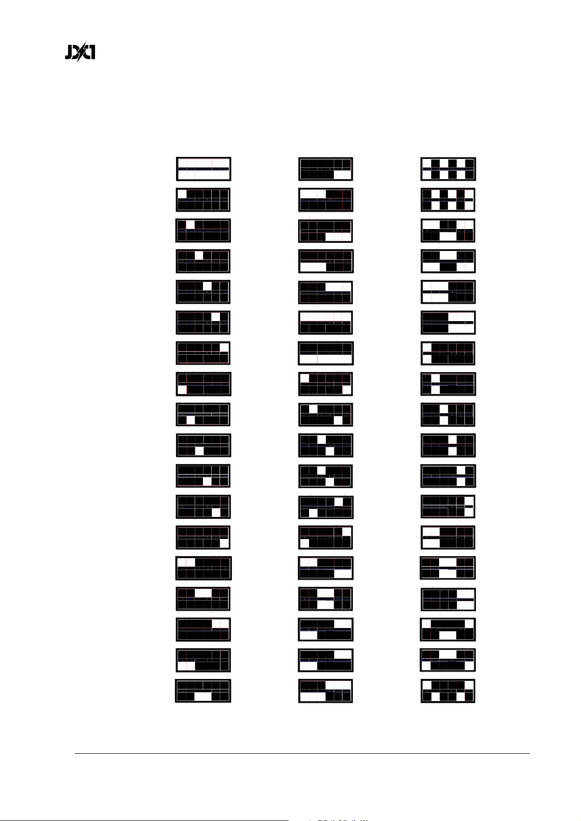
www.glp.de
9. Plate FX patterns
You can display the following dynamic patterns on the Plates in DMX modes 2 and 3
by sending the indicated DMX values on channel 17:
0-2
3
4
5
6
7
8
9
10
11
20 38
21 39
22 40
23 41
24 42
25 43
26 44
27 45
28 46
29 47
12
13
14
15
16
17
18
19
31 49
30 48
32 50
33 51
34 52
35 53
36 54
37 55
60 JDC1
User Manual Rev. 3.0
Page 61
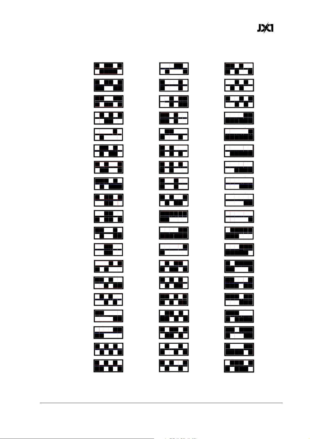
German Light Products®
56
57
58
59
60
61
62
63
64
75 94
76 95
77 96
78 97
79 98
80 99
81 100
82 101
83 102
65
66
67
68
69
70
71
72
73
74
85 104
84 103
86 105
87 106
88 107
89 108
90 109
91 110
92 111
93 112
JDC1 User Manual Rev. 3.0 61
Page 62
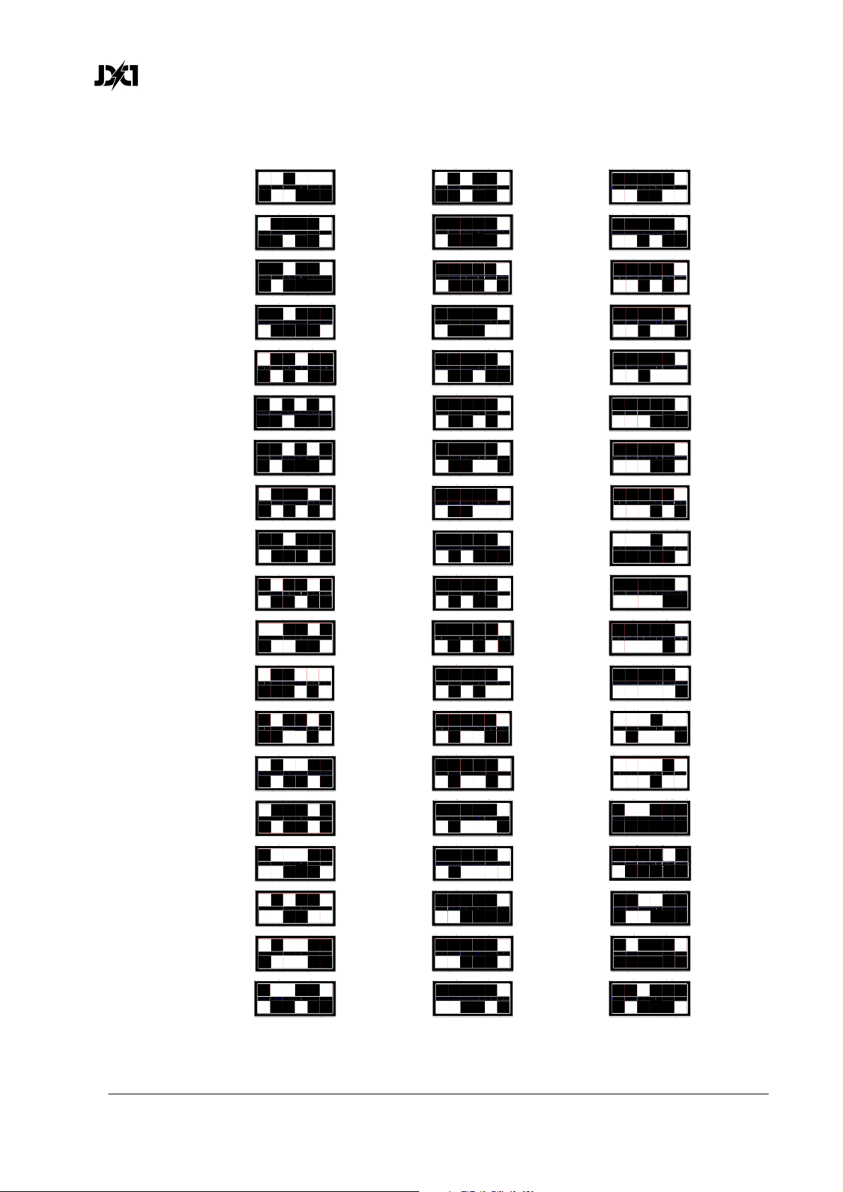
www.glp.de
113
114
115
116
117
118
119
120
121
122
133 152
132 151
134 153
135 154
136 155
137 156
138 157
139
140
141
158
159
160
123
124
125
126
127
128
129
130
131
142
143
144
145
146
147
161
162
163
164
165
166
148 167
149 168
150 169
62 JDC1
User Manual Rev. 3.0
Page 63
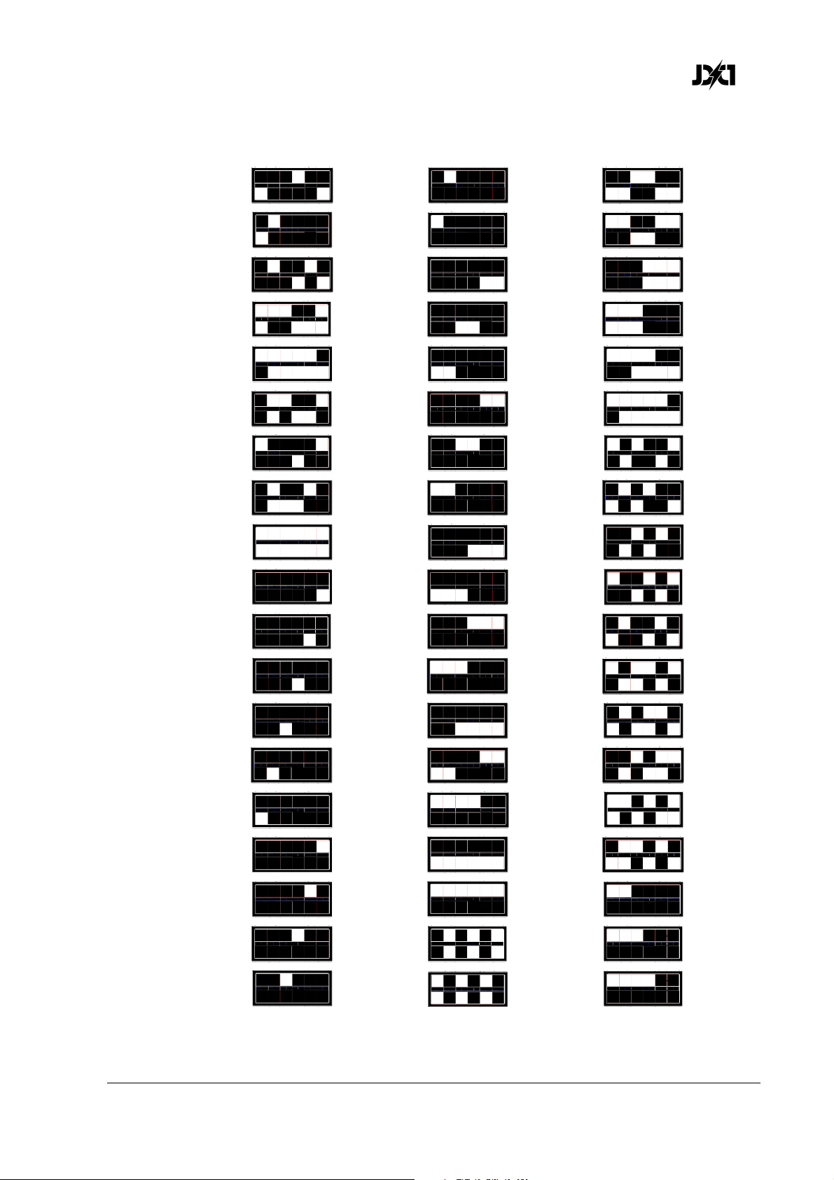
German Light Products®
170
171
172
173
174
175
176
177
178-180
181
191 210
192 211
193 212
194 213
195 214
196 215
197 216
198 217
199 218
200 219
182
183
184
185
186
187
188
189
190
201 220
202 221
203 222
204 223
205 224
206 225
207 226
208 227
209 228
JDC1 User Manual Rev. 3.0 63
Page 64
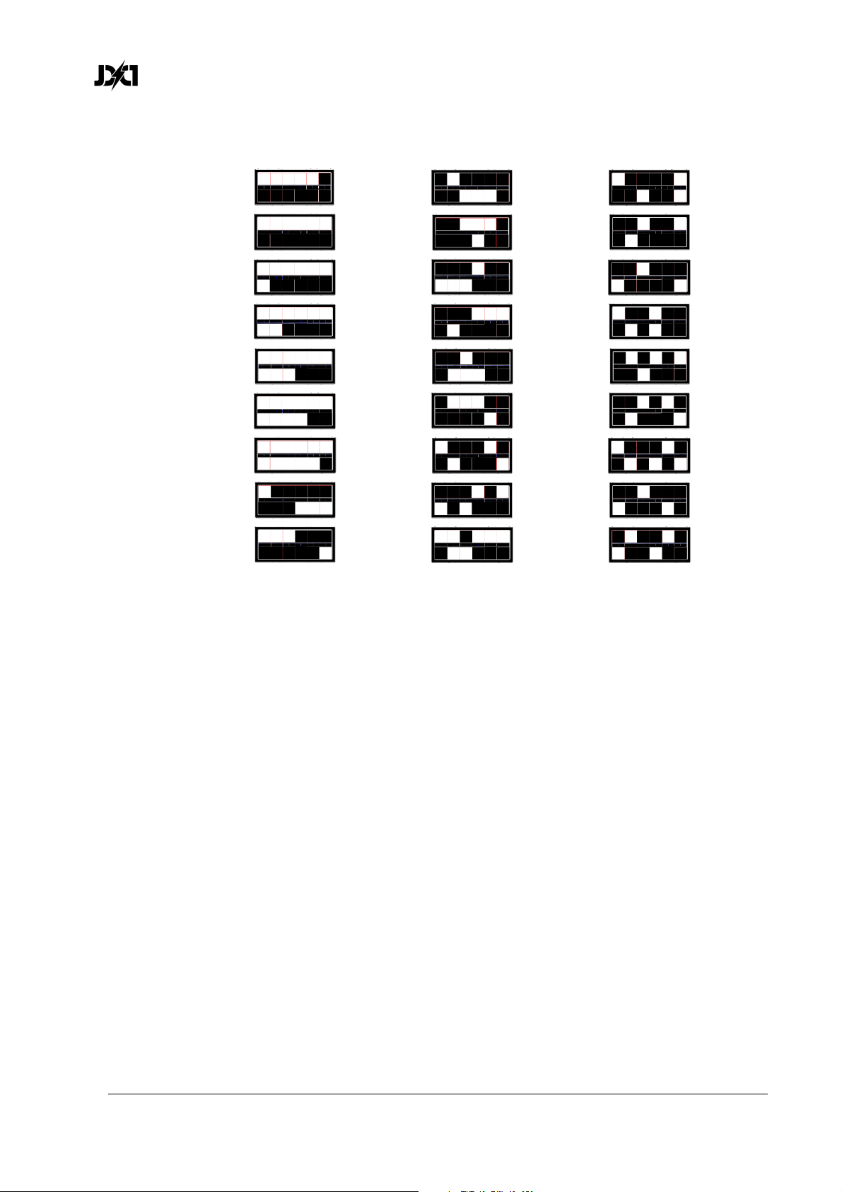
www.glp.de
229
230
231
232
233
234
235
236
237
238 247
239 248
240 249
241 250
242 251
243 252
244 253
245 254
246 255
64 JDC1
User Manual Rev. 3.0
Page 65
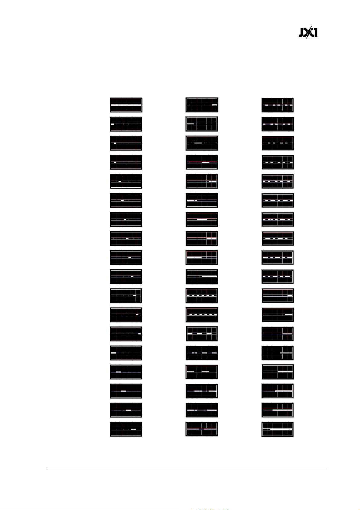
German Light Products®
10. Beam FX patterns
You can display the following dynamic patterns on the Beam pixels in DMX modes 2
and 3 by sending the indicated DMX values on channel 19:
0-2
3
4
5
6
7
8
9
10
11
20 38
21 39
22 40
23 41
24 42
25 43
26 44
27 45
28 46
29 47
12
13
14
15
16
17
18
19
30 48
31 49
32 50
33 51
34 52
35 53
36 54
37 55
JDC1 User Manual Rev. 3.0 65
Page 66
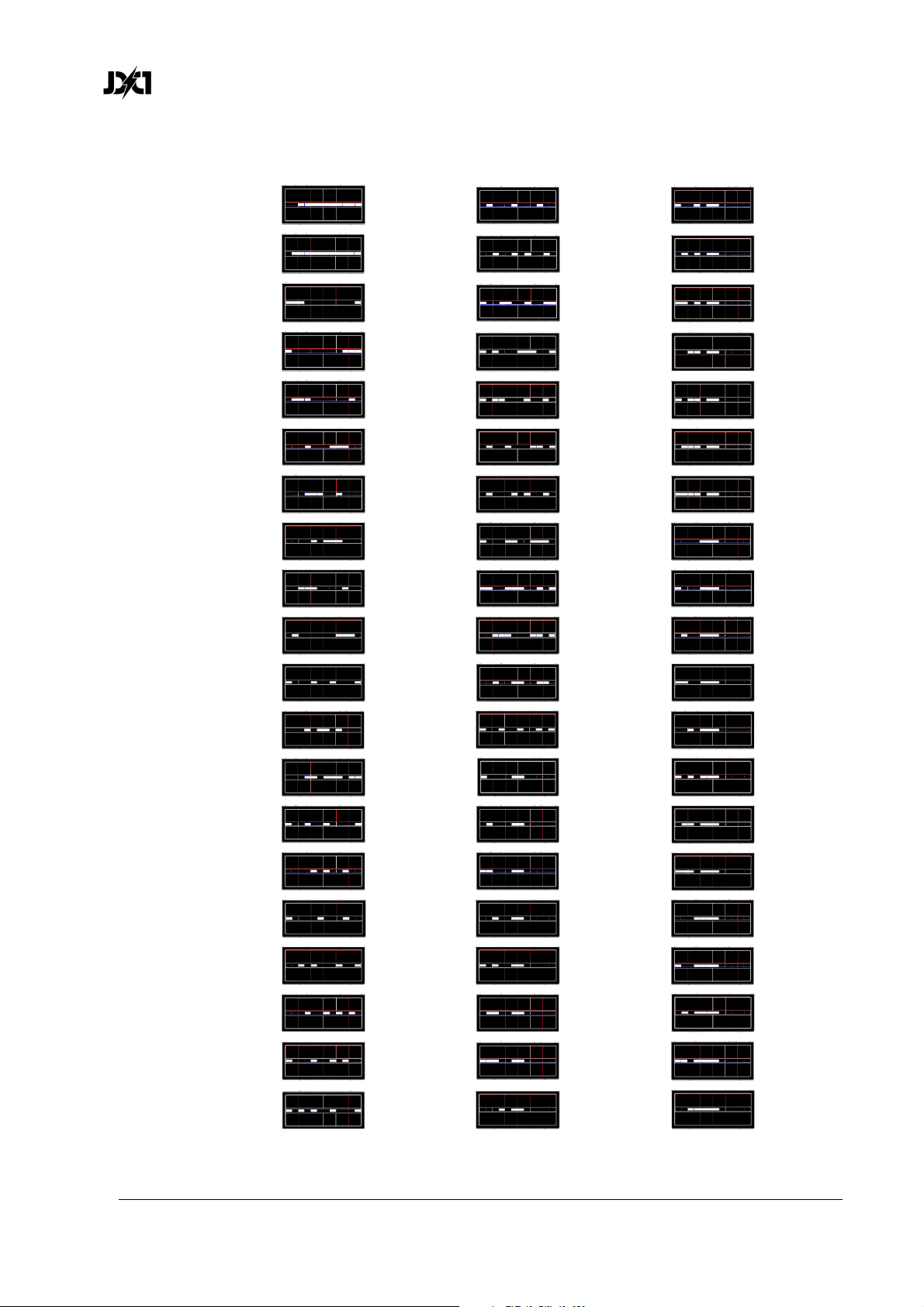
www.glp.de
56
57
58
59
60
61
62
63
64
76 96
77 97
78 98
79 99
80 100
81 101
82 102
83 103
84 104
65
66
67
68
69
70
71
72
73
74
85 105
86 106
87 107
88 108
89 109
90 110
91 111
92 112
93 113
94 114
75
95 115
66 JDC1
User Manual Rev. 3.0
Page 67
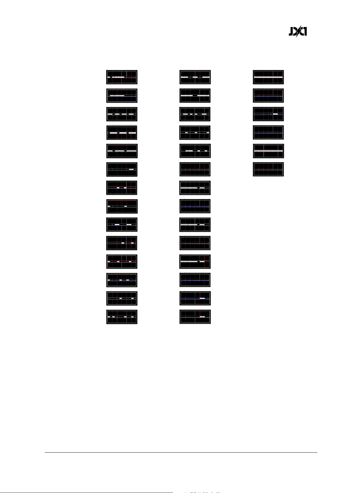
German Light Products®
116
117
118
119
120
121
122
123
124
125
130 157
131 158-160
132 161
133 162-164
134 165
135-145 166-255
146
147-149
150
151
126
127
128
129
152
153-154
155
156
JDC1 User Manual Rev. 3.0 67
Page 68
www.glp.de
11. Cleaning and maintenance
WARNING! Any service operation that requires removal of a cover must be
performed by a professional service technician with the necessary tools,
skills and personal protective equipment to maintain high-powered
lighting equipment safely and efficiently.
Suggested maintenance intervals
The cleaning schedule depends on the operating environment. The intervals below are
suggestions from our experience with typical installations. Adjust as necessary.
Maintenance task Interval How
Front glass Weekly Soft cloth and glass cleaning fluid
Fans and air channel Monthly Vacuum cleaner, compressed air, etc.
Moveable parts Yearly Suitable lubricant
Cleaning
JDC1 components require occasional cleaning to prevent the buildup of dust, dirt,
and smoke fluid residue. Pay special attention to the air vents and glass plate. Failure
to keep the fixture clean will significantly reduce light output and may cause damage.
Regular cleaning will ensure maximum performance and reliable operation.
You can clean the front glass with household or automotive glass cleaning products.
GLP Service and Support
Contact information for the nearest GLP Service and Support is available online at
www.glp.de/en/service, by email at [email protected], or by telephone at the following
numbers:
• GLP Germany: +49 (7248) 927 19-55
• GLP N. America: +1 818 767-8899
• GLP UK: +44 1392 690140
• GLP Asia: +852 (3151) 7730
• GLP Nordic: +46 737 57 11 40
68 JDC1
User Manual Rev. 3.0
Page 69

German Light Products®
12. Technical Specifications
Strobe panel LEDs
LED Type: OSRAM LRTB GVTG
LED Count: 1320
LED Colors: RGB
LED Segments: 12 (2 x 6)
Strobe tube LEDs
LED Type: CREE XP L LED
LED Count: 216
LED Colors: Cool white
LED Segments: 12
Movement
Resolution: 8 - 16 bit
Position feedback: Yes
Tilt: 185 °
Connectors
Signal connection: XLR 5-pin input and output
Power input: Neutrik powerCON TRUE1
Operating conditions
Mains voltage: 100-240 VAC / 50-60 Hz
Power (@ 230V): 1200 W
Fuse: 6.3 x 32 mm T15A
Maximum ambient temperature: 45° C / 113° F
Operating position: Any
Shipping options
Single fixture: Cardboard (Product code
Tourpacks: 4-way and 8-way incl. flightcase
Dimensions and weight
Length: 154 mm (6.1 in)
Width: 390 mm (15.3 in)
Height (head horizontal): 284 mm (11.2 in)
Weight: 10.8 kg (24 lbs.)
Weight incl. bracket: 12 kg (26.5 lbs.)
7675)
JDC1 User Manual Rev. 3.0 69
Page 70
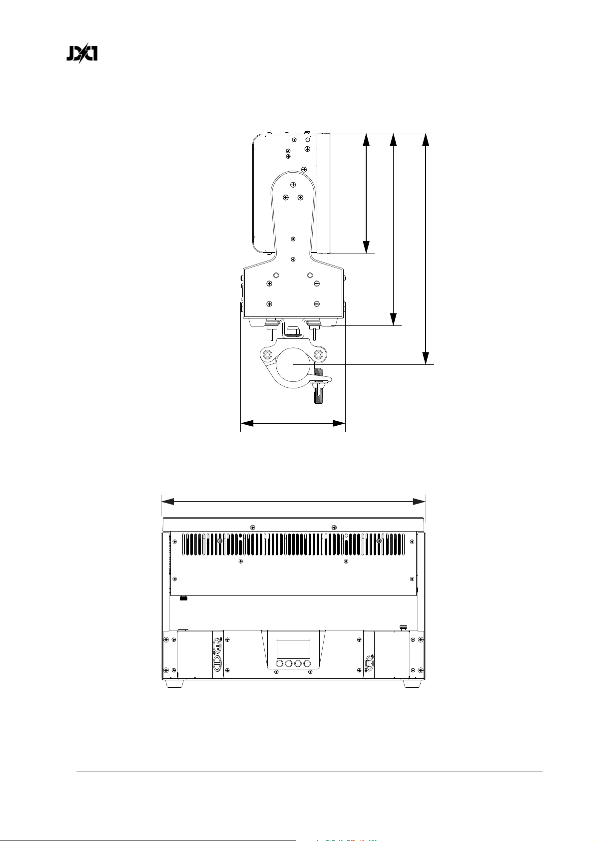
www.glp.de
13. Dimensions
178 mm
284 mm
342 mm
154 mm
390 mm
70 JDC1
User Manual Rev. 3.0
Page 71

Page 72

 Loading...