

Page 1

Instruction for use
Gerkros KT/KST Boiler
Technical Manual
Page 2

2
Puttingtheboilerintooperation
CONDENSATIONWALLGASBOILERS
Beforefirstputtingintooperationitisnecessarytotakefollowingsteps:
Procedureofthefirstboilerburning:
:
Theboilermustbeputintooperationbyaserviceworkertrainedbyproducer!
1.Checkwhethertheheatingsystemisfilledwithwaterandtheboilerisdeareated
properly.
2.Makesureifallthevalvesareopen.
3.Openthegasvalveinstalledpriortotheboilerandtestthesealingofthegas
pipingintheboiler.
1.Plugthefeedingflexintothe230V/50Hzsocket.
Testthesocketwithanotherappliance.
2.Settheheatingtemperatureandswitcharoomthermostat(if
connected)on.
3.Putthemodeswitchtothepositionwinter.
4.Checktheproperoperationofallthethermostatsandcontrolelements.
5.Settheboileroutputbytherequestofheatedplace.
ATTACKKT,KST-
TheboilerissetbytheproducertonaturalgasG20,inletgaspressure20mbar,
ortoLPGgasG31,inletgaspressure37mbar.
Beforeinstallationandputtingtheboilerintooperationitisnecessarytoget
acquaintedwiththeinstructionforuse.
TheboilerisofIIcathegory.
TheKTboilerisofB,C,C,C,C,Ctype.
2H3P
331333435383
Page 3

3
Contents:
4Introduction
4Generaldescription
5Purposeofuse
5Technicaldescription
6Conditionsofattendance
6Controlfrontboardoftheboiler
7Specialsymbols
8Puttingtheboilerintooperation
Settingthetemperatureofheatingwater
9Settingthesummermode
Thewayofregulation.Boileroperationwithexternalhotwatertank
10Informationmode
Historyofbreakdownsandoperationconditions
Errorreport
11Equithermalregulationoftheboiler
13OutsidedimensionsoftheKTboiler
14OutsidedimensionsoftheKSTboiler
15ThemainpartsoftheKTboiler
16ThemainpartsoftheKSTboiler
17Supervisionoveroperation
Spareparts
Guarantee,reclamation
Service
18Maintenance
Wrapping,transport,storing
Accessories,documentation
19Technicalparameters
20Installation,conditionsofinstallation
21Localizationandmountingoftheboileronthewall,condensateoutlet
22Installationmodeoftheboiler,testingmode
23Connectingtheboilertotheheatingcircuit.Connectingtothecentralheatingsystem
andgaspipe-line.
24Thechartofconnectingtheboilertowaterandgas.
25Connectingtothemains
26Wastegasexhaust
27ATTACKKTandKSTaccessories
28Connectingaroomthermostat.Connectingacoaxialpipeforwastegasexhaustand
puttingtheboilerintooperation
29ThechartofATTACKKTconnecting
30ThechartofATTACKKSTconnecting
31Settingthegasvalve
32Othersettings,circulationpumpcharacteristics
33-34Notes
35Recordonputtingtheboilerintooperationandobligatoryserviceinspection
Technicalmanual
Page 4

4
Boileroutput
Turbotype
Condensationboiler
7-25kWKT
7-25kWKST
Boileroutput
Condensationboiler
Turbotype
Through-flowheatingofwater
Introduction
Dearcustomer,
Generaldescription
DescriptionofATTACKKTandKSTboilersbrand:
ThankyouforconfidenceexpressedbypurchasingourproductATTACKKT,KST
wallgasboiler.Wewishyoulongandreliableoperation.Properattendanceofthe
boilerisoneoftheconditionsforreliableandrightoperation,sopleasereadthis
instructionforusecarefully.Themanualiswritteninthewaytorespecttheright
operationoftheboilerincentralheatingsystem.
Theconditionsofrightoperationoftheboiler:
-tochoosetherighttypeandoutputoftheboiler
-impeccableputtingintooperation
-sensitiveattendance
-regulartechnicalmaintenance
-reliableservice
Thelatestproducedrangeofcondensationwallgasboilersisdesignedasan
appliancewithmaximumeffectivityandminimumemissionsintoatmosphere,
savingenvironmentconsiderably.Maximumoutputoftheboileris25kW.High
technicallevelofboilersissupportedbyusedtopcomponentsfromworld
producers.ATTACKboilersareproducedaccordingtorequestsofISO9001and
areproperlytestedbytechnicalandstandardizationinstitutewhichissuedtheCE
certificatestotheboilers.
Fortherightoperationoftheboileritisnecessarytokeepaminimumwater
pressureof1bar(measuredwhenthewateriscold)intheheatingsystem.
NOTICE:
Page 5

5
Purposeofuse:
Technicaldescription
ThetyperangeofATTACKKT,KSTcondensationwallboilersisproducedwithmodulating
outputof7-25kW,whichmeansthatbytheinstantneedforheatintheobjecttheboiler
choosesoptimalheatingoutput.ATTACKboilersareusedforcentralheatingoffamily
houses,flats,shopsandsimilarplaceswherethefuelisnaturalgas.
Astouse,theboilerisbuilttooperatewithheatingwatertomaximumhydrostaticpressureof
0,3Mpa(3bar)andoperatingtemperatureto85ºCwithconnectiontoheatingcircuitswith
forcedflowofwaterintheclosedsystem.Waterintheheatingcircuitmustsuittostandards
bySTN077401(itmustnotbesourinanycase,whichmeansthatitmusthavethepH-value
higherthen7andminimumcarbonatehardness,max.3mval./1-1)Fillingpressureincold
systemisof11,5bar.Fillingmustbedoneslowlyforairbubblestoescapethroughproper
deareatingvalves.Foradjustingthewaterhardnessintheheatingsystemitisnecessarytouse
recommendedagents.
CondensationwallgasboilerATTACKKTisamodernsourceofthermalenergysuitablefor
heatingandpreparationofhotwaterinanexternaltank.ThecondensationKSTboileris
equippedwithaspecialsecondaryboardheat-exchangerwherehotwaterispreparedby
through-flowheating.ATTACKcondensationboilersareequippedwitaspecialsteeltwochamberheatexchanger.Inthefirstchamber(non-condensationchamber)wastegas
transfersheatbutdoesnotcondensate.Inthesecondone(condensationchamber)wastegas
condensatesandtransferssocalledcondensationheatpresentinwastegastoheatingwater.In
thisprocess,acondensateisproducedwhichiscollectedbycondensatecollectorandled
throughasiphonawayfromtheboiler.Theheatexchangerisequippedwithtwoelectrodes.
Oneofthemservesforburning,theotheroneforionizationflameguardingintheheat
exchanger.Ontheheatexchangerthereisalsoanautomaticdeareatingvalveandheatsensor
foroutcomingheatingwater.Removablewalloftheheatexchangerisequippedwitharing
burnerandpipebringingamixtureofgasandairtoaburningspace.Gasismixedwithairina
deviceconsistingofgasvalveandaVenturitube.
Inletofairforburningisenabledbyafanwithcontinuouslycontrolledrevolutionswhich
allowsoutputmodulationoftheboilerinawiderange.Wastegasisdrawnbyacoaxialor
doublewastegasexhaust.CirculationofheatingwaterisdonebyaGrundfoscirculation
pump.Inthecaseofhigherpressureintheheatingcircuit(when,forexample,alltheheadsof
heatingbodiesareclosed),intheboilerthereisaby-passvalvethatopensashortcircuitinthe
boilerandtheoutputismodulatedwithoutanynegativeconsequences.Formeasuring
temperatureandpressuretherearesensorswhichshowthevaluesonthedisplayoftheboiler.
ControlofATTACKKT,KSTcondensationboilersprovidesanextremelycomfortable
attendance.Theremotecontroloftheboilerisdonebyalltheaccessibleperipheraldevice
thatiscompatibleincommunicationwithOPENTHERM.Equithermalregulationprovides
economyoffuelanddiminishedwearofsinglecomponents.Thisregulationtakescareof
propertemperatureofheatingwaterbythecalculationaccordingtooutsidetemperature.The
displayaswellascontrolbuttonsarelaidoutonthecontrolboard.Fortherightoperationof
theboilerthereisamicroprocessorunitthatmonitorsandevaluatesinstantaneousconditions
oftheboilertoreachoptimizationandeconomyoffuelformaximumutilizationofthe
appliance.
Inthecaseofnotfollowingtherulesabovethereisnoguarantee
fordamagedcomponents.
Page 6
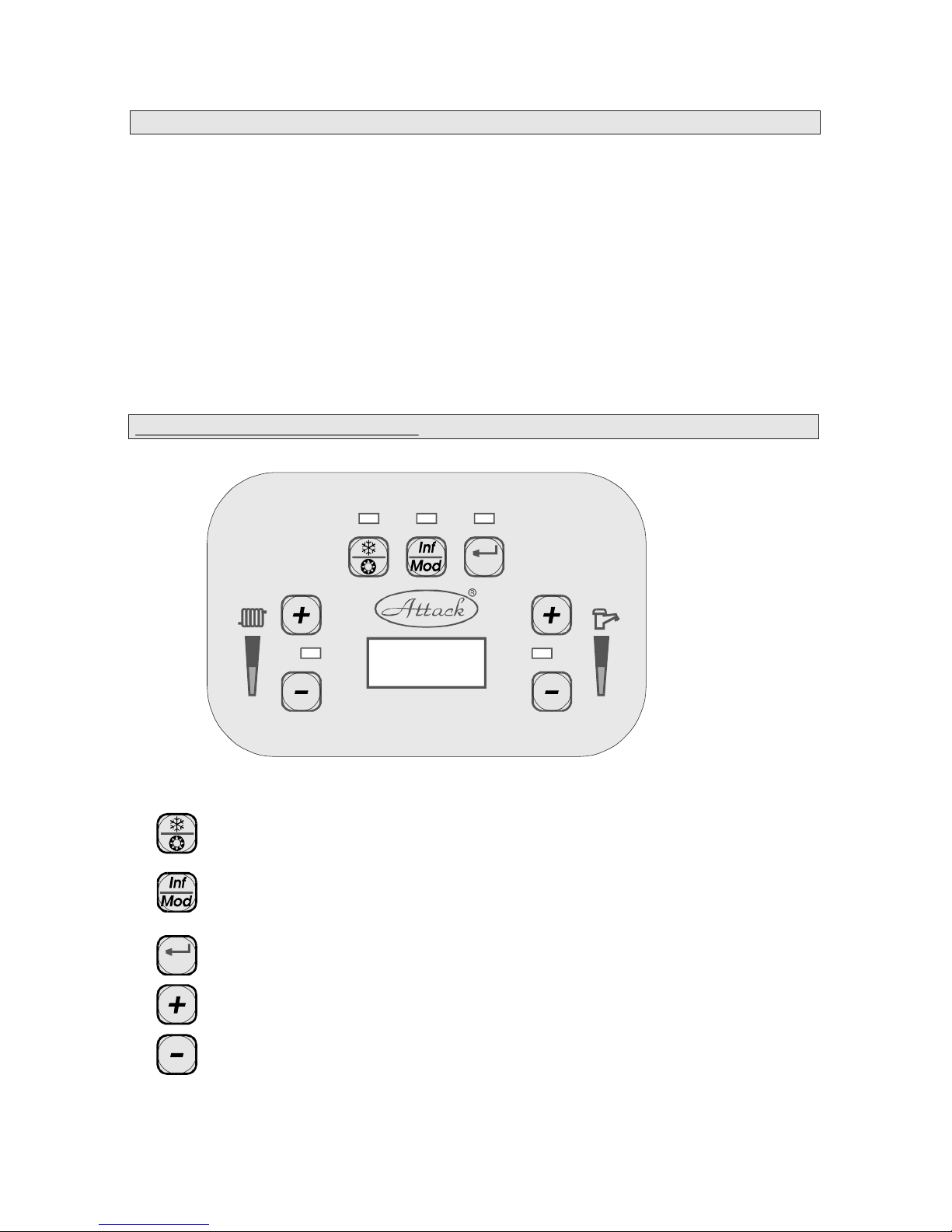
6
Reset
Reset
usedforswitchingonandoffandforchangingthemode(summer-winter)
usedforparametersofthecontrolboard(temperatureofhotandheatingwater,
waterpressure,outsidetemperature,Kfactor)
usedforincreasingtemperatureofhotandheatingwater
usedfordecreasingtemperatureofhotandheatingwater
Enter,Reset
Conditionsofattendance:
Theattendanceoftheboilermustbecarriedoutbytherulesdescribedinthismanual
whichisapartofdeliveredconsumerdocumentation.Exceptattendance,theusermust
notcarryoutanyrepairsontheappliancenoradjustmentsorunmountingandcleaning
theinsidepartsoftheboiler.Theboilercanbeoperatedonlybyanadult.Afterleaving
homeinwinter(onholiday...)asupervisionbyatrainedpersonisneeded.Ifthereisa
dangerofapproachofinflammable(combustible)gasesorfumestotheboiler,itmustbe
putoutofoperationsoon.Theuserishastotakecareofrightuseoftheboileraccording
tothisinstructionwhichisalsoaconditionforacknowledgementofguarantee.When
puttingtheboilertooperation,theserviceworkermustinstructtheuserhowtooperate
theboilerTheuserwithhisorhersignatureintheletterofguaranteeconfirmshaving
beeninstructedintheboilerattendance.
.
Controlfrontboardoftheboiler
Page 7
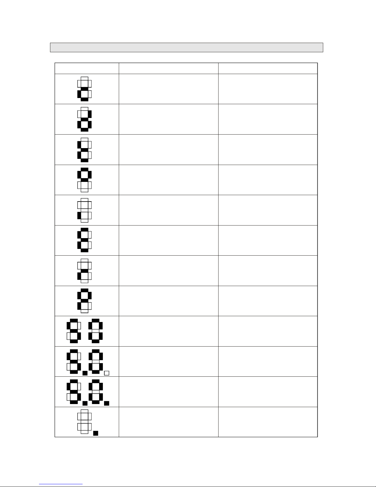
Specialsymbolsandtheirexplanation:
Symbol MeaningExplanation
CentralheatingSymbolforcentralheating
HotwaterSymbolforhotwater
Testingmode
DegreeofCelsius
Index
Error(E)
Error(r)
Paramater
50
Normalinicationofvalue50
150Pointindicatesvalue100
250Twopointsindicatevalue200
FlamePointindicatesflamedetection
7
Page 8
8
Puttingtheboilerintooperation:
Settingupthetemperatureofheatingandhotwater
Firstputtingtheboilerintooperationcanbedoneonlybyatrainedauthorizedservice
partneroftheATTACKcompany.Whenoperatingtheboiler,ausercanmanipulateonly
withcontrolelementsandafillingvalve.Thisvalveisnotapartoftheboiler,buttheheating
circuitmustbeequippedwithit.Whenstartingtheoperation,itisnecessaryforallthe
connectinglines(connectionofheatingsystem,ofnaturalgasandcondensateoutlet)tobe
sealedandtestedbyrevisions.Forfillingtheheatingcircuititisrecommendedtousesoft,
filteredrainwater.Waterhardnessintheheatingcircuitcannotbehigherthan3mval/l.When
puttingtheboilerintooperation,checkwhetheralltheclosingvalvesareopen.Plugthe
cableintothesocket.
Afterplugginginthedisplayofthecontrolfrontboardshowstheinformationonthe
softwaretypeoftheproductfor2seconds.
Ifthereisnorequestforheatingandnobreakdownregistered,thedisplayshowscurrent
outlettemperatureofheatingwater.TheboilerisintheSTAND-BYmode,readyfor
operation.Ifthepressureofheatingwaterislowerthan0,8bar,E37errorisindicated.
Currentpressureofheatingwaterinthecircuitcanbedisplayedintheinformationmode(see
thepartInformationmode).Ifthedisplayedvalueofpressureislowerthan0,8bar,itis
necessarytoincreasethesystemto11,5barusingthefillingvalve.Afterincreasingthe
pressure,thevalveistobeclosed.Thefillingvalveshouldbeequippedbyanon-returnflap
valvetopreventcontaminationofdrinkwaterbywaterfromtheboiler.Thiscouldhappenif
thefillingvalvewasnotclosedproperlyandpressureintheheatingcircuitwashigherthan
pressureofwaterinpiping.
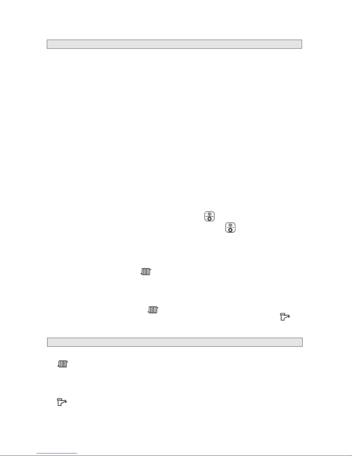
Theboilercanbesetintowintermodebythebutton__________.Operationoftheboilerin
thewintermodeissignalizedbyLEDdiodeoverthebutton__________,whichisnot
shining.Inthismodetheboilerisreadyforheatingintheheatingsystem.
IftherequestforheatingcomesfromthethermostatorfromcontactsoftheOPENTHERM
communication,theboilerisputintooperationwithinafewseconds.Thedisplayshows
currenttemperatureofheatingwater.Asmallredlightintherightlowercornerofthedisplay
signalsthattheboilerhasstartedcorrectlyandthemainburnerisoperating.
TheLEDdiodeatthesymbol_________isshining,signalizingtherequestfromthe
thermostatforheating.Whentherequestisattheend,thediodegoesout.
TheATTACKKTboilerisalsoequippedwithanti-cyclingfunction.Aftertherequestfor
heating,anti-cyclingtimeisactivatedduringwhichtheboilerwillnotrespondtotherequest
forheating.Afterthistimetheboilerisrestarted.Anti-cyclingtimeissignalledbyflickering
oftheLEDdiodeatthesymbol_________.
Ifthereisarequesttoheatwater,theLEDdiodeonthefrontboardatthesymbol_______
lightsupandcurrenttemperatureofhotwatercomingoutoftheboilerisdisplayed.
Thetemperatureofheatingwatercanbechangedbythebuttons+/-atthesymbol
_________.Withthehelpofthebutton+therequiredtemperatureisrisenandwiththe
helpofthebuttonthetemperatureislowered.Thetemperatureisshowedonthedisplayof
theboiler.Therequiredtemperatureisconfirmedandsavedintothememoryautomaticlyif
in5secondsthevalueisnotchanged.
Thetemperatureofhotwatercanbealsochangedwiththebuttons+/-,butatthesymbol
________,whilethetemperatureisbeingdisplayed.Therequiredtemperatureissavedifthe
temperatureisnotchangedin5seconds.
Page 9

9
Settingupsummermode
Thewaysofregulationoftheboiler
Operationoftheboilerwiththethrough-flowheatingofwater(KST).
Operationoftheboilerwiththeexternalhotwaterstoragetank
Summermodeissetupbythebutton___________.Theoperationoftheboilerinthe
summermodeisdisplayedbytheloghtofLEDdiodeoverthebutton_______.Theboilerin
summermodeignoresanyrequestforheatingfromtheroomthermostatorOPENTHERM
contacts.
Theboilerinsummermodecanonlypreparehotwater.Summermodeoftheboilerisalsoa
standbymodeforactivatinganti-freezingfunctionandprotectionofthepump.
Anti-freezingfunctionprotectstheboileraswellastheheatingcircuit.Ifthetemperatureof
heatingwaterdropsunder6°C,theboilerstartsworkingtominimumheatingoutputandturns
offafterhavingreached15°Ctemperatureofheatingwater.
Automaticprotectionofthepumppreventsblockingthepump,soifitisnotworkingmore
than24hours,thepumpisactivatedfor30seconds.
1.Operationwithoutaroomthermostatinthiscaseitisnecessarytohaveaconnectionon
theterminalboardbetweenT1andT2contacts.Thisconnectionismadefromtheproduction
unit.Theboilerpreparesheatingwatertothechosentemperature.
2.Operationwitharoomthermostattheboilerisregulatedbytheroomthermostatandkeeps
thesetuptemperatureofheatingwater.TheroomthermostatisconnectedtotheT1andT2
contactsontheterminalboardinsteadofadisconnectedjumper.Or,insteadoftheroom
thermostat,aregulatorsuchasHONEYWELLCX51,CR11010whichapartfromother
functionsalsoservesasaroomthermostat,canbeconnectedthroughOPENTHERM
contacts.
.Operationoftheboilerbytheoutsidetemperature.Theboilerhasanoutsidesensorof
temperature(HoneywellSO10075)andanequithermalcurveischosen.Totheboilercanbe
alsoconnectedaroomthermostatwhichinfluencesswitchingonandoffoftheboilerandthe
temperatureofheatingwaterissetautomaticlybytherealoutsidetemperature.
Fortheoperationoftheboilerwithathrough-flowheatingofwater(KST),thedemandfor
heatingisrecordedbythethrough-flowsensorofhotwaterrespondingtohotwater
withdrawal.Themaximumconnectingpressureofhotwatercanbeof6bar.Intheareas
withhigherhardnessofwateritisnecessarytosoftenthewaterenteringtheboilertoprevent
incrustationoftheboardheatexchangerforhotwater.
FortheoperationwiththeexternalhotwaterstoragetankitisnecessarytoconnecttotheL,
N,Rcontactsontheterminalboardthedriveofathree-wayvalvewithoutamicroswitchand
totheS1,S2contactsasensorforhotwatertemperature.Theboilerprepareshotwaterin
winteraswellasinsummermodewhilehotwaterisaprioritytotherequestforheating.If
theboi
Ù
Note:ThecontactroomthermostatcannotbeusedontheOPENTHERMcontacts.Theseare
forconnectingtheregulatorthatiscompatibleincommunicationwithOPENTHERM.
3
Incaseofincrustationoftheboardheatexchangercausedbyoperationonhardwater
thereisnoguarantee.
lerworkswithouthotwaterpreparation,theS1andS2contactsareconnectedwitha
connectionequippedwitha2,2kresistor.
Accessoriesforconnectionoftheexternalhotwaterstoragetank:
1.Three-wayvalveHoneywell1“+VC6013MP6000drive
orthealternationthree.wayFUGAS ľ“valve+drive(codeRZ18+RZ19)
2.HoneywellSO10045hotwatersensorusedforthesleevewith1mcable.
Page 10
10
Reset
Reset
Reset
Informationmode
Historyofbreakdownsandoperationconditions
Errorreports
Informationmodecanbeactivatedbypressingthebutton_________.Byrepeatedpressing
itispossibletoscantheseindexes:
Index
1Currentintensityoftheflame
2Currenttemperatureofoutletheatingwater
3Currenttemperatureofreturningheatingwater
4Currenttemperatureofhotwater
5Pressureintheheatingsystem
6Applicationtype
7Currenttemperatureofwastegas
8Currentflowrateexpressedbythefrequencyofthesensor(Hz)
9Currentcalculatedvalueofoutletheatingwaterbytheoutsidetemperature(inthe
modeofequithermalregulation)
10Currentvalueofoutsidetemperature
Theinformationmodecanbefinishedbypressingthebutton_________.Themodeis
automaticlyfinishedifin1minutenochangeisdone.
Bykeepingthebutton_________forthetimelongerthan3minutesthehistoryofboiler
breakdownsisactivated.OnthedisplaythereissymbolEwithrelevanterrorcode(see
chartoferrorreports).Searchinginthelistofbreakdownsismadebythebutton
_________andserialnumberoftheerrorandsymbolEaredisplayedalternately.
Thismodecanbestoppedbypressingthebutton________again.Thehistoryof
breakdownsendsautomaticlyafter30secondssincelastchange.
IncaseofanyerroronthedisplayappearsthesymbolEwithrelevanterrorindex.
Chartoferrorreports:
Index
01Flameblockingaftersomeunsuccessfulattempts
02Falseflamesignal
03Safetythermostatopen
05Errorincommunicationbetweencontrolelectronicsandventilator
07Hightemperatureofwastegas,TTBsensor
----08Errorintheflamecircuit
09Errorinthegasvalvecircuit
10ErrorinthecommunicationwiththememoryofEEPROMcontrolelectronics
11emperatureofreturnheatingwaterishigherthantemperatureofoutletheating
water
21ADCHuperror(InternalerrorofCVBCelectronics)
Page 11
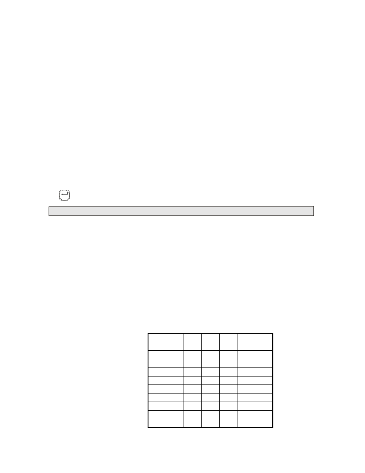
11
C
1
2
3
4
5
6
7
8
9
10
C120100-10-20
1
2
3
4
5
6
7
9
12
18
3032.53537.540
3035404550
3037.54552.560
3040506070
3042.55567.580
3045607590
3047.56582.590
3052.5758590
3060858590
3075858590
Reset
22ADCLuperror(InternalerrorofCVBCelectronics)
25InconsistencybetweenHupandLupCRC(InternalerrorofCVBCelectronics)
30Temperatureofheatingwaterisoutofworkingrange(closedcircuitshort-circuit)
31Temperatureofheatingwaterisoutofworkingrange(opencircuit
notconnected)
32Temperatureofhotwaterisoutofworkingrange(closedcircuitshort-circuit)
33Temperatureofhotwaterisoutofworkingrange(opencircuitnotconnected)
34Lowfeedingvoltage(lessthan185VAC,ifthevoltagereaches190250VAC,the
erroriseliminated)
35Frequencyoffeedingvoltageisintherangehigherthan+/-5%
36Bigrangeofbottomandtopvalueoffeedingvoltage
37Lowpressureofwaterintheheatingsystem
41Temperatureofwastegasisoutofworkingrange(closedcircuitshort-circuit)
42Temperatureofwastegasisoutofworkingrange(opencircuit
notconnected)
43Temperatureofheatingwateristoohigh
Errorsfrom143arerecordedinthememoryofboiler.Eliminationoftheerrors
1,2,3,5,7,11happensafterre-establishingconditionsinworkingrange,withoutusing
________.
Whentheoutsidesensorofoutsidetemperaturetotheterminalboardisconnected(OT1
andOT2contacts)andequithermalcurveCisdetermined(parameter15Installationmode
oftheboiler),theboilerstartsworkinginthemodeofequithermalregulationof
temperatureofheatingwaterbytheCcurve.Thetemperatureofheatingwaterinthiscase
isautomaticlyadjustedtotheoutsidetemperaturebythisformula:
T=K+C1*(20-outsidetemperature)/4K-constant(parameter10installationmodeof
theboiler)
T=30°C+C1*(20-outsidetemperature)/4
C1isderivedbyCcurveinthisway:
IfC=1.....7thenC1=C
IfC=8thenC1=9
IfC=9thenC1=12
IfC=10thenC1=18
Equithermalregulationoftheboiler
hw
hw
Page 12
12
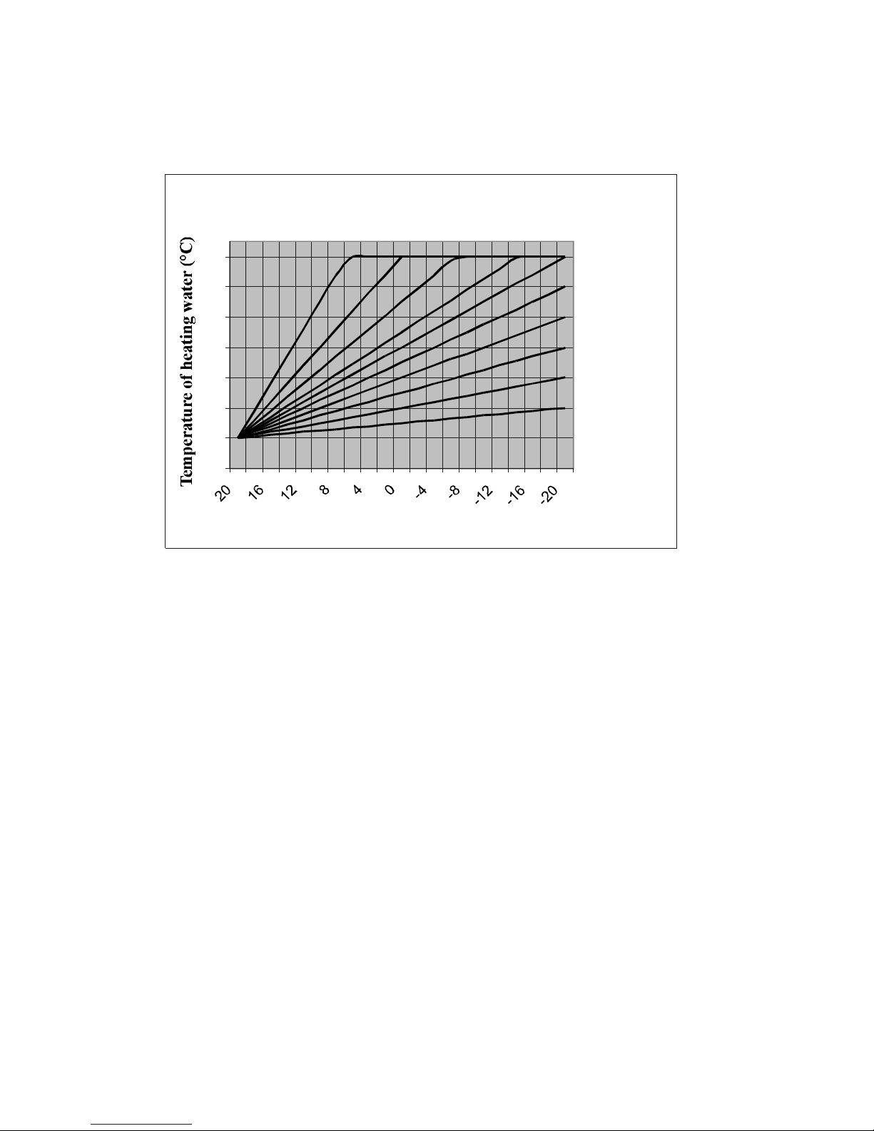
Ekvitermickékrivky"C"
20
30
40
50
60
70
80
90
Vonkajšiateplota(°C)
10
9
8
7
6
5
4
3
2
1
EquithermalcurvesC
Outsidetemperature(°C)
ThisgraphshowstemperatureofheatingwaterindependanceontheCcurveandoutside
temperature.SettingtheCcurveismadeintheinstallationmodedescribedindetailsinthe
part
Forsettingup,variousenteringvaluesareimportante.g.heatinglossofheatedbuilding,
heatingtemperatureofthebuilding,etc.
WhendecidingforthesuitableCcurve,itisnecessarytorealizethatifthecurveistoo
steep,thebuildingwillnotbeheatedbyequithermalregulationbuttheregulationwillbe
donebyroomthermostat,sotheadvantagesoftheequithermalregulationwillbelostand
thesystemwillreactonlytothetemperatureofthesurroundings.Ifthecurveistoo
shallow,thetemperatureofheatingwaterwillnotbehighenoughtoensurecomfortinside
theheatedbuilding.
Forinitialsettingup,wechoosethecurveC=5andafterwardschangeitproperlybythe
respondoftheheatedbuilding.Theresultofsettingupisthattheroomthermostatswitches
theboileroffveryrarelyandtheboilerisoperatinginthelongestpossibleintervals.The
generalruleisthatashallowcurveissuitableforwellinsulatedbuildings(C=1,2,3)and
forbuildingswithhigherthermallossesasteepercurveissuitable(C=6,7,10).
Theadvantageofequithermalregulationistoheattheplacebythelowestpossible
temperatureofheatingwaterinthelongestpossiboleperiodstoensurepermanent
temperatureofheatingbodies.Astheheatingbodiesarealwaysheated,theyproduce
permanentheatradiation,makingtheuser´scomfortbetter.Aftersettinguptheequithermal
curveitisnecesarytowaitoneortwodaystogetthethermalresponseoftheplaceand
watchtheroomthermostatwhetheritdoesnotswitchofftoooften.Incaseitswitchesoff
toooften,theplaceisheatedmainlybytheroomthermostatanditisnecessarytoreduce
thesteepnessoftheequithermalcurve.Theoutsidesensorfortheequithermalregulationis
usuallyplacedonthenorthernornorth-westernsideofthebuilding.
Installationmodeoftheboiler.
Page 13
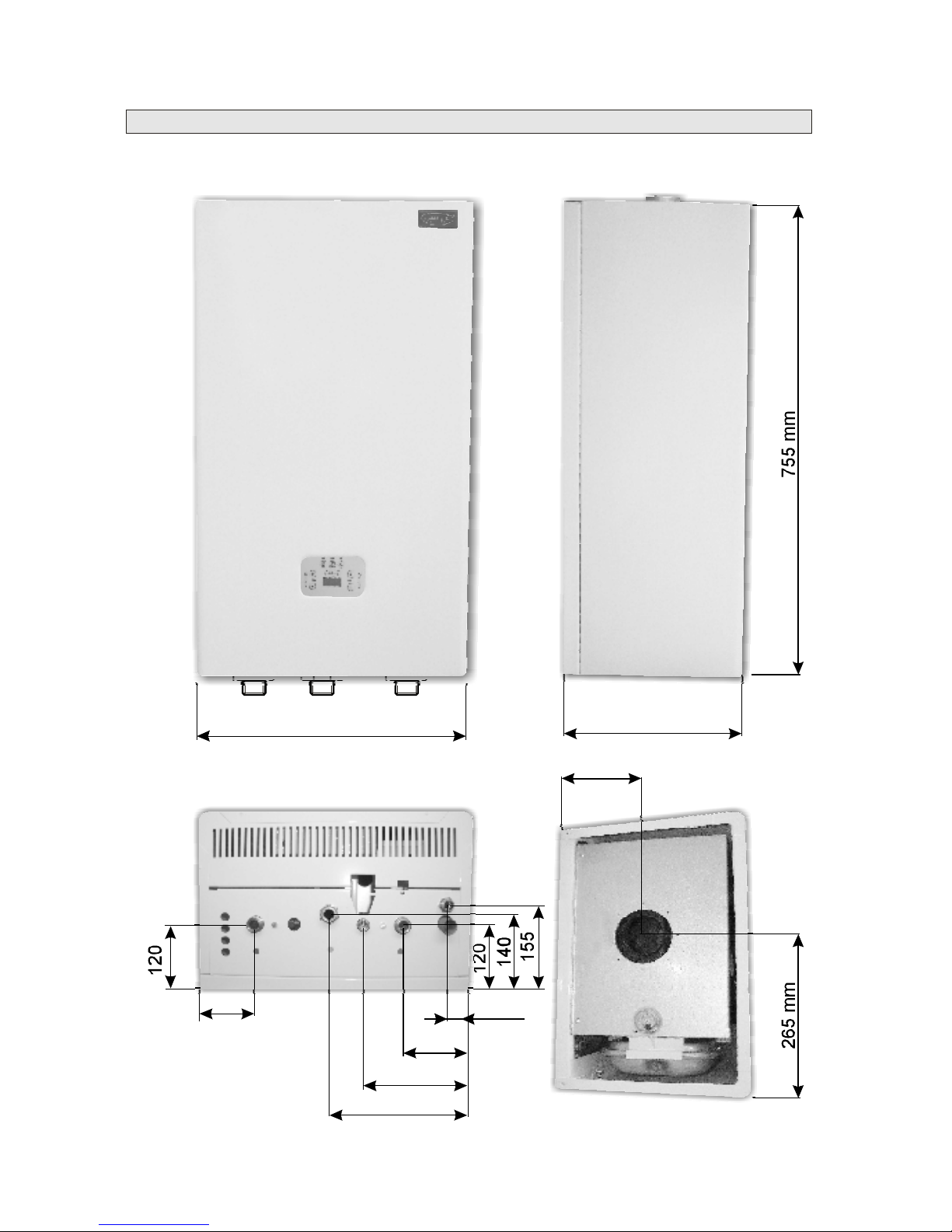
122
240
105
48
185
13
OutsidedimensionsofATTACKKT
470mm
310mm
150mm
Page 14
14
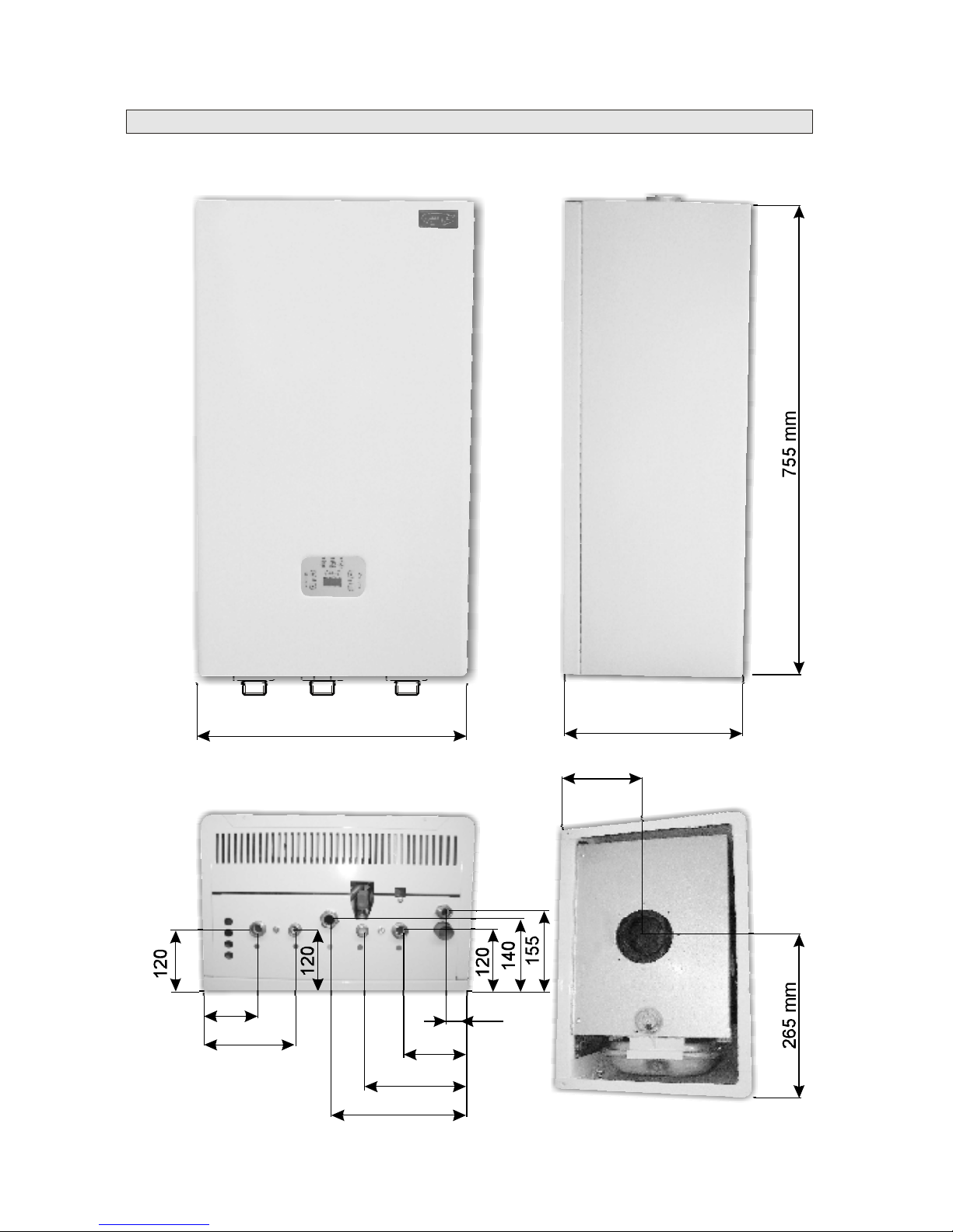
OutsidedimensionsofATTACKKST
470mm
310mm
150mm
122
240
170
105
48
185
Page 15
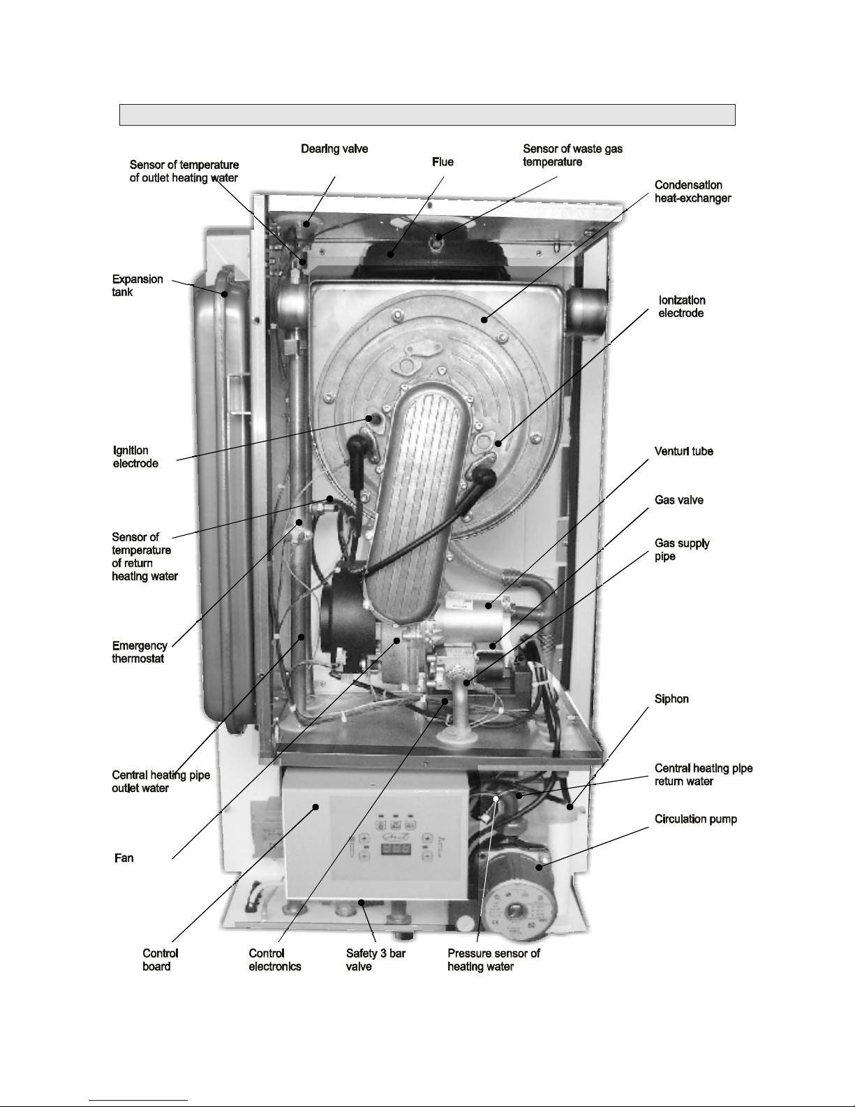
15
MainpartsofATTACKKTboiler
Page 16
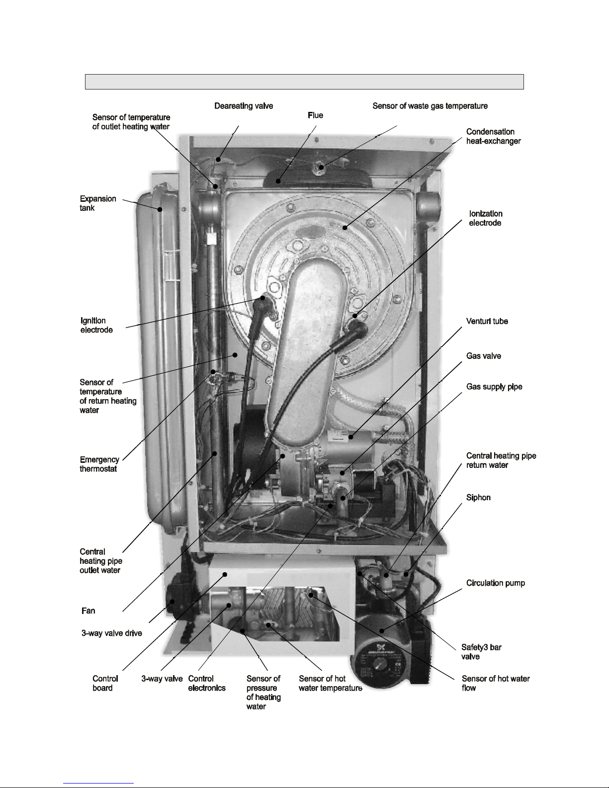
MainpartsofATTACKKSTboiler
16
Page 17

17
Supervisionoveroperation
Spareparts
Guarantee,reclamation
Service
Duringtheoperationtheboilerissecuredagainstdangerousoperationconditions.However,
thebreakdownswiththecausenotincludedintheboilermechanismcannotbeprotectedto
arise.Thereforeitisnecessaryafterputtingtheboilertooperationtoexaminetheboilerevery
threedaysandcheck:
a.whetherthesystemisfilledwithwaterandthereisnoleakage.Ifthepressuredropsunder
0,8barintheheatingcircuitinthecoldcondition,itisnecessarytoincreasethepressurewith
thehelpofthefeedingvalveto11,5bar.
b.whetherwastegasesorgascannotbesmelled.Incaseofgasleakageputtheboileroutof
operation,closethegassupplyandcallservice.
Theproducerkeepssinglepartsofboilersassparepartswhichareprovidedforguaranteeand
postguaranteeserviceonlytocontractpartnersonthebaseoforderorreclamation.
Theexactreadingofguaranteeandguaranteeconditionsandhintsforreclamationare
includedintheletterofguarantee.Repairsintheguaranteetimeareperformedonlyby
contractservices.
Attention!
Aftereachyearoftheoperationduringtheguaranteetimeitisnecessarytogettheboiler
examinedandadjustedbyacontractcompany.Theguaranteewillnotbeadmittedunlessthis
isperformed.Evenafterfinishingtheguaranteetime,theproducerrecommendsany
interventionsaimingtorepairstobemadeonlybyacontractservicepartner.Theactivitiesof
theboileruserinthepostguaranteetimearedeterminedinthepart„Maintenance“.
Foundbreakdownsmustbereportedtotheserviceworkerwhoputtheboilertooperation.
Ifthereisagasleakage,thegassupplymustbeclosed.Foundbreakdownsmustbe
removedimmediately.
Torespecttheconditionsofguarantee,theproducerdoesnotpermitperforminganyrepairs
byacompanyotherthanacontractorserviceintheguaranteetime.
Page 18

18
Maintenance
Wrapping,transport,storing
Boileraccessoriesanddocumentation
Regularmaintenanceisimportantforreliableworking,longlifetimeandcombustion
effectivityoftheboiler.Theuserisrecommendedtocontactacontractserviceorganization
nearbyandensureregularannualexaminations(seeconditionsforguarantee).Aservice
workercheckscontrolandsafetyelementsoftheboiler,gasandwaterdistributionsealing
orcleanstheburnerandexchangerfromburntdustparticles.Incaseoflowerpressureitis
necessarytorefillwaterintocoldheatingcircuit.
Approximatelyonceamonth,theusershouldcheckwhethercondensaterunsoffinto
sewage.Checkingandcleaningoffiltersoftheheatingsystemshouldbedoneafterfirst
heating,firstweekofoperationandregularlybythedegreeoffoulingofheatingcircuit.
Boilersaretransportedinhorizontalposition.Topreventpossibledamage,theyare
protectedbyacartonwrapping.Thewrappingissecuredbyanadhesivetape.Theboiler
mustbestoredinnon-aggressivespacewiththetemperatureof+5upto+50°Cin
maximumrelativehumidityofairof75%,withoutpresenceoforganicsteams,gasesand
dust.
ATTACKKT,KSTboilersaredeliveredcompletelyassembliedandtestedduetooperation.
Thedeliveryincludes:
wallbracket
instructionforusewithadocumentofboilertestingonthebacksideoftheinstruction
–letterofguarantee,listofcontractpartners
–coaxialpipe60/100mm1m
–coaxial90°elbow
–sealing
Otheraccessoriesnotdeliveredwithboilers:
Page 19

19
Technicalparameters
Cathegoryoftheappliance................................................................................II
Type........................
Typeofgas...............................................................................Naturalgas(G20),LPGG31
Feedingpressureofnaturalgas....................
FeedingpressureofLPGgas(mbar)..................
Heatinput(max/min)kW................
Thermaloutputtemperaturedrop50/30°C(max/min)kW........
Thermaloutputtemperaturedrop80/60°C(max/min)Kw..........
Naturalgasconsumption(max/min)mh.........................
LPGgasconsumption(max/min)mh.............................
Noiseness(1mfromtheboiler,1,5height)dB(A)..................
Wastegasrateofflow(max.output)g/s...................................
Wastegasmax.temperature(max.output,50/30°C/80/60°C)°C..............
NOxclass................................................................
COcontentinwastegas(%)..............
Nominalefficiencyfortemperaturedrop50/30°C(%)......................
Nominalefficiencyfortemperaturedrop80/60°C(%).............
Therangeoftemperatureofheatingwaterinheatingmode°C..........
Expansiontankvolume(l).....................................................
Max.workingoverpressureofheatingwater(bar)...........................
Min.workingoverpressureofheatingwater(bar).............................
Max.workingtemperatureofheatingwater(°C)..............................
SurroundingsbySTN332000-3..............................................................normalAA5/AB5
Hotwaterpreparationmode(onlyforATTACKKST)
Set-uprangeofhotwater(°C)...........................
Hotwaterpassagethermaldifference35°C(l/min)..................
Hotwaterpassagethermaldifference25°C(l/min)..................
Minimumhotwaterpassage(l/min).................
Rangeofworkingoverpressureofhotwater(bar)...............
Electricitydata
Electricalsupply/Frequency(V/Hz)..............
Elect.supplyoncontactsofroomthermostat(V)..................
Output(W).................................................
Nominalfusecurrent(A).....................................................
Electricstandard...............................
Dimensions
Width/Height/Depth(mm).............................................
Weightwithoutwater(kg)....................................................
Connection
HeatingInlet/Outlet(G).................................................
Gas(G)...........................................................................
Diameterofcondensateexhaust(mm)...................................
Wastegasexhaust
Max.lengthof60/100coaxialexhausthorizontal(m)..................
vertical(m).................
Max.sumofdouble-pipe80mmexhaustlengths(m)....................
2H3P
2
3/
3/
Ø
Ø
.....................................................................B,C,C,C,C,C
....................................................20
..............................................37
............................................................23,4/7,1
…...............25/7,5
….........22,4/6,8
.........................2,46/0,74
.............................0,95/0,3
........................<50
.........................13
.....52/77
.............................................5
..............................................................8,7%
...............107
.........................97
..........30-90
..............................7
...................3
................0,8
..................85
...............................................35-65°C
...........................9
.........................13
..................................................2,2
..............................1-6
..................................................230/50
............................230
...........................................................120
.....................................2
....................................................................IP44
….............................465/800/310
.................................35
.....................................3/4"/3/4"
........................................3/4"
................................13
……………..3
........................2,7
.......................10
331333435383
Page 20

20
TECHNICALMANUALFORASSEMBLY
ANDSERVICECOMPANIES
Installationofboilers
Installationconditions:
Aboilercanbeinstalledonlybyacompanywithavalidcertificateforinstallationand
assembly.Fortheinstallationitisnecessarytoworkoutaprojectthatsuitstovalidrules.
Connectingoftheboilermustsuittovalidstandards,rulesandinstructionforuse.
Agasboilercanbeinstalledonlybyacompanyauthorizedtocarryouttheseworks.
Beforeinstallation,theinstallingcompanyhastochecktherightchoiceoftheboilertype
withregardtothefunctionalattributesandrequiredparameters.TheboilerhasanIP41
coveringofelectricpartsthatisresistentagainstwaterdroppingvertically.Thereforeitcan
beinstalledinbathroomsbytheSTN332000-7-701standardinzone3(inthedistanceof
60cmfromtheedgeofthebathorshowercorner).Duringinstallationtheremustbe
protectionagainsttheinjurybyelectricity.Theroomwheretheboilerislocatedmusthave
thetemperatureintherangeof+5to+35°Cwithrelativehumidityto80%.
100mmtomaterialsoflowandmediumflammability
200mmtomaterialsofhighflammability(e.g.fibreboards,polyurethane,polyethylene,
expandedPVC,rubber...)
DuetofiresafetytheboilermustbeinstalledandoperatedinaccordancewiththeSTN92
0300.
Thefirstputtingintooperationandtrainingoftheboileroperatorsmustbedonebya
contractservicepartneroftheproducerthatmakesregularmaintenanceaswellas
guaranteeandpost-guaranteeserviceoftheboiler.Tothesupplygaspiping,ahandygas
valvemustbeinstalledpriortotheboilerwhichmustbeaccessiblebutisnotapartofthe
boileraccessories.TheboilerisconnectedtotheheatingsystemthroughscrewjointsG
¾“.GasinletisconnectedthroughscrewjointsG¾“.Beforeinstallingtheboileritis
necessarytomakesurethatthechosenplacefitstorequirementsforwastegasescapeand
thatminimumdistancesbeforementionedarekept.Asthisboilerisfast-heating,equipped
withitsownpump,itispossibletoconnectitwithgravitycirculationaswellastoanew
systemforforcedwatercirculationintheheatingsystem.Fornewdistributionswe
recommendtousesmall-volumeheatingbodiesanddistributionsinthesmallest
dimensionsbecauseoffastheatingofthesystemtothetemperatureanditsbigflexibility.
Connectingoutletsoftheboilershouldnotbestrainedwhenconnectingtheboilertothe
heatingsystemandtothegasdistribution.Beforeconnectingtheboilertotheheating
systemitisnecessarytoflushitoutthoroughlytoremovesmallimpuritiesandmud.
The
producerisnotresponsiblefordamagescausedbyfaultyinstallation.
ItisnotallowedtoplaceobjectsclasifiedbytheSTN730823closetotheboiler,inthe
distanceshorterthan
Page 21
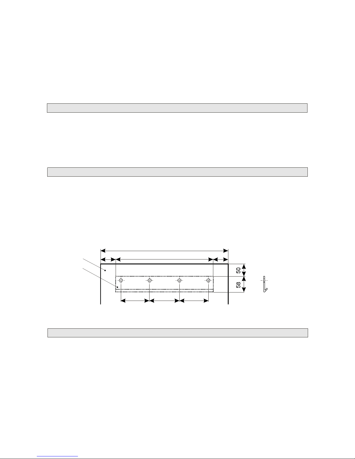
465mm
8080
195 195 195
305mm
boiler
wallbracket
21
Theheatingsystemmustincludeaproperfilter.Toutilizethemaximumoutputofthe
boileritisnecessarytoensureminimumpressureintheheatingsystemof0,8barforright
operationandlonglifetime.Abuiltexpansiontankenablesconnectingtheboilertothe
closedheatingcircuit.Theboileristooperateonnaturalgasof20mbarnominalpressureor
LPGof37mbarnominalpressureinthedistributionnet.Theboilerislocatedsoastoensure
necessaryoperatingconditionswithregardtothewaysofcombustionairsupplyandwaste
gasexhaust.
Localizationofboilersmustsuittoprojectdocumentation.Boilersaretobesituatedinthe
waytoensurealltheoperationconditionsneededandwithregardtothewayofcombustion
airsupplyandwastegasexhaust.Fromthesidesofboilerstheremustbefreeaccessofat
least0.2mandinfrontofboilers1mforassemblyandservice.Boilersmustbeinstalledat
least0,1moverthefloor.
Mountingtheboilersonthewallmustbeperformedonthebaseofqualifiedassessmentof
thewallbearingcapacity(byaprojectworkerorassemblycompany)soastoguaranteesafe
andreliablehangingofboilers.Theboilerhangsonawallbracketwhichmustbemounted
tothewallwithasuitableconnectingmaterial(e.g.screwsanddowels)regardingthequality
ofthewallandweightoftheboiler.
Condensateproducedduringtheoperationoftheboilermustbedrainedoffconstantly.The
diameteroftheoutletsystemmustbeatleast13mm.Fortheoutletofcondensatetosewage
itisnecessarytofollowproperlocalandnationalrules.Ifneeded,neutralizationdevicecan
beused.Condensatecannotbegatheredinanycase,thereforetheoutletmustbeinmin.
slopeof3%tosewagedownwardsfromtheboiler.
Localizationofboilers
Mountingtheboilersonthewall
Condensateoutlet
Page 22
22
Reset
Reset
Reset
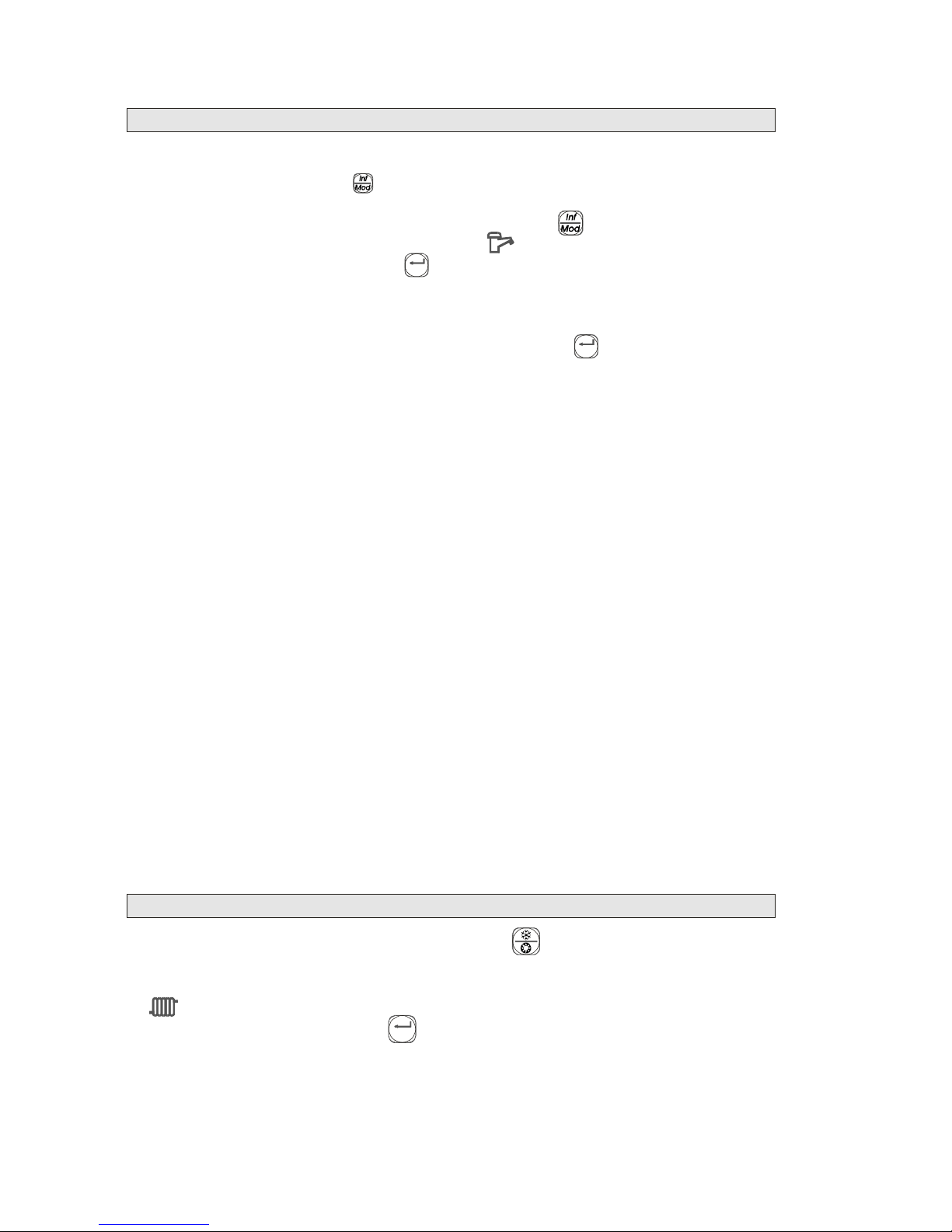
Installationmodeoftheboiler
Testingmode
Installationmodeservesforsettingupvariousparametersofboileroperation.Thismode
isactivatedbypressingthe______buttononthecontrolboardformorethan3seconds.
ActivatedinstallationmodeissignalledbyflashingsignalizationLEDdiodeabovethe
button.Parametersareselectedbypressingthebutton_______.Changeofaparameteris
donebypressingbuttons+/-nearthesymbol______.Recordtomemoryoftheboileris
confirmedbypressingthebutton______in5secondsfromchoosingtherightvalue.This
timeperiodisindicatedbyflickeringredLEDdiodeabovethisbutton.
Ifthechangeisnotconfirmed,thevalueisnotrecordedintothememoryandlastvalue
donebeforethischangeisvalid.
Theinstallationmodeisfinishedbypressingthebutton_______incasetheredLED
diodeabovethisbuttonisnotflickering.Theinstallationmodeisalsofinishedifthereis
noactivityformorethan1minute.
Listofparameters:
1Raiseoftemperatureatstart(°C/min)inheatingmode(0-60)4
2Anticyclingtimeinheatingmode(s)(0-255)90
3Kpfactorinheatingmode(-)(0-255)2
4Kifactorinheatingmode(-)(0-255)62
5Kpfactorinhotwatermode(-)(0-255)3
6Kifactorinhotwatermode(-)(0-255)93
7Startingoutput(%)(0-70)50
8Kpfactoroftheventilator(-)(0-255)35
9Kpfactoroftheventilator(-)(0-255)230
10Heating-set-upparameterbyoutsidetemperature(°C)(20-40)30
11Currentheatingtemperature(°C)
12Run-outofthepumpinheatingmode(min)(1-20)5
13Currenthot-watertemperature(°C)
14Maximumoutputoftheboilerinheatingmode(%)(0-100)100
15Heatingcurvebyoutsidetemperature(-)(0-10)0
16Run-outofthepumpinhot-watermode(s)(0-255)30
17Hysteresisinheatingmode(°C)(0-10)3
18Hysteresisinhot-watermode(°C)(0-20)5
19Maximumvalueoftemperatureinheatingmode(°C)(20-90)80
Testingmodeisactivatedbypressingthebutton_______formorethan3seconds.The
functionoftestingmodeissignalledbyflickeringsignalizationLEDdiodeatthisbutton.
Duringtestingmodeitispossible,withbuttons+/-,tosetupoutputatthesymbol
_______whichisgiveninpercentanddisplayed.Ifyouwanttofinishthetestingmode,
youcandothatwiththebutton_______.Durationofthetestingmodecanbesetuporit
finishesautomaticlyiffor30minutesthereisnochange.
Par.No.DescriptionSet-uprangeSelectedvalue
Page 23

23
Connectingtheboilertoheatingsystem
Connectingtheboilertohotwaterpiping
Connectingtheboilertogaspipeline
ATTACKboilersserveforheatingsystemswithforcedcirculation.Rateofwaterflowcanbesetby
theswitchonthepump.Beforefillingtheheatingsystemwithwater,itisnecessarytocleanthe
systemproperly.Heatersanddistributionmustbeflushedoutseveraltimes.Forthoroughflushing
andcleaningoftheheatingsystemwerecommendtousecleaningagents.Ontheinletfromheating
systemtotheboiler,afiltermustbemounted.Werecommendbrassfilterswithsidecleaning.The
filtersmustbecleanedregularlyaccordingtofouling.Maintenanceoftheboileriseasierwhenonthe
inletaswellasontheoutletofheatingthereisavalve.Filtersandvalvesarenotdeliveredasboiler
accessories.Theheatingsystemmustalsobeequippedwithafeedingvalvewithnon-returnflapvalve
connectedtowaterpipingthatservesforfeedingandpressurizingtheheatingsystem.
Thehardnessofwaterintheheatingsystemisnotrecommendedhigherthan3mval/l.Intheboiler
thereisa7-litrepressureexpansiontankenablingconnectingtoaclosedheatingsystem.Ifitis
requiredbythesizeoftheheatingsystem,anotherpressureexpansiontankistobemounted.The
recommendedtemperaturedifferencebetweenoutcomingandincomingheatingwaterfromthe
boileris15-20°C.Forreconstructionofheatingoranewsystemwerecommendsmall-volume
heatersanddistributionsinthesmallestdimensionsregardingtofastriseofthesystemtothe
temperatureandquiteabigflexibilityofthesystem.Processofwaterfilling:whenfillingwithwater,
theboilermustbedisconnectedfromelectricity,deareatingvalvesontheboilerandheatingsystem
mustbeopen.Setthesystemtothepressureof1bar,thendeareateandsettothepressureagain.
Heatingsystemmustsuittovaluablestandardsandmeasures:
STN060310Projectandassemblyofcentralheating
STN060830Equipmentforcentralheating
ThesizeofexpansiontankbySTN060830iscalculatedbyformula:
V=V.v.1.3
V=volumeoftheexpansiontank
V=volumeofheatingwaterinthecircuit
v=proportionalgrowthofvolumeafterheatingtotIft=80°C,v=0.029
Ifthevolumeoftheexpansiontankishigherthan7litres,itisnecessarytoaddanotherexpansion
tankwithminimumsizeequaltocalculateddifference.Becauseofmaximumutilizationof
condensationeffectitisnecessaryfortheheatingsystemtobedimensionedtotemperaturedropof
50/30°C.Theboilerisequippedwithasiphonthatbeforestartmustbeflushedoutwithwaterof
about100ml.Theoutletfromthesafety3barvalveisnecessarytoconnecttothedischarge
piping.
ConnectingtheboilertohotwaterpipingmustbedoneinaccordancewiththestandardSTN06
0830.Thepipingmustbeequippedwithallthedeterminedfittings.Maximumfeedingpressureof
hotwateris6bar.Hardnessandcompositionofwatermustsuittovalidstandardsfordrinking
water.
Beforeconnectingaboilertothegaspipeline,thepipelinemustbetestedandadjusted.After
connectingtoaboiler,allthegasconnectorsmustbetested,includingpipingandfittingsinthe
boiler.Boltedconnectionsofthegaspipelineaswellasthoseofthewaterpipingandheating
waterpipingmustnotbestressedbyanyadditionalforce.Gasinstallationmustbedoneaccording
tothestandardSTNEN1775.
Guaranteedoesnotapplytothecasesofcloggingtheexchangerorpumpbyimpuritiesfromthe
system.
C
C
mm
Guaranteedoesnotapplytothecasesofincrustationoftheheatexchangerorpump.
Page 24
24
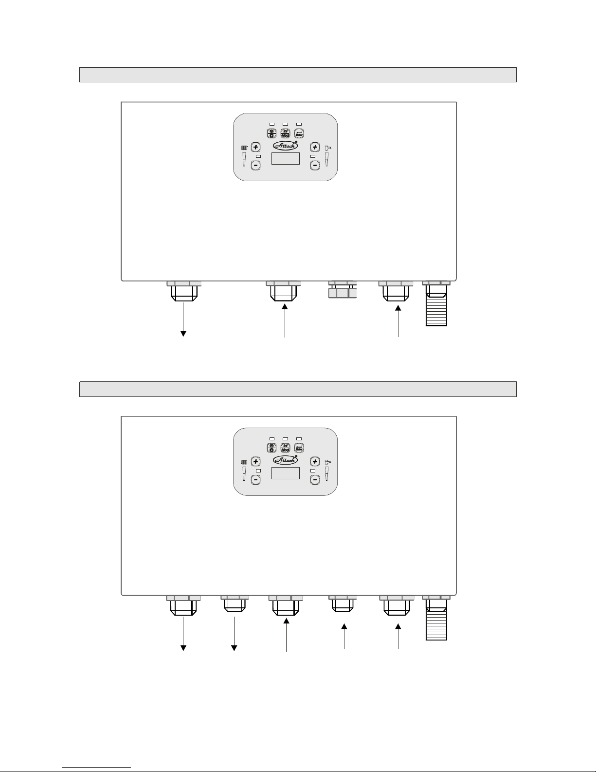
Gasinlet
3/4”
Heatinginlet
3/4”
Heatingoutlet
3/4”
ChartofconnectingtheATTACKKTboilertowaterandgas
ChartofconnectingtheATTACKKSTboilertowaterandgas
Hot
water
outlet
1/2”
Condensate
outlet
3-barvalve
Inletof
refilling
waterin
heating
circuit
Heatingoutlet
3/4”
Gasinlet
3/4”
Heatinginlet
3/4”
Condensate
outlet
3-barvalve
Hot
water
inlet
1/2”
Page 25

25
Connectingtheboilertothemains
Theboilerispluggedintothesocketof230V/50Hzwithamainscablewithaplug.The
socketmustsuittoSTN332000-4-46standardanditmustbeequippedwithacentre
contactpinconnectedtoPEconductor.Variousmultiplesocketsandlenghteningcablesare
notallowedtouse.Mainssupplymustbeof230V/50Hz.Installationofthesocket,
connectingtheroomthermostatandserviceofelectricpartsoftheboilercanbeperformed
onlybyapersonwithspecialelectricqualification.Electricinstallationisreadyfor
additionalconnectionofaroomthermostatandthree-wayvalveincaseindirectlyheated
storagetankwasconnected.Theroomthermostatmustbeconnectedbyacopperconductor
with1-1.5mm.Theoutsidethermalsensormustbeconnectedwithacopperconductor
with0.75mmdiameter. Ù
2
2
Maximumresistanceofthelineis10k,totallength30m.Forthe
OPENTHERMcontactscanbeusedacopperconductorwith0.5-1.5mmdiameter.The
conductorsoftheoutsidethermalsensorandOPENTHERMcontactscannotbeconducted
concurrentlywiththeconductorsoftheroomthermostatandmainsfeed.
2
Page 26
26
Waste-gasexhaustKT,KST
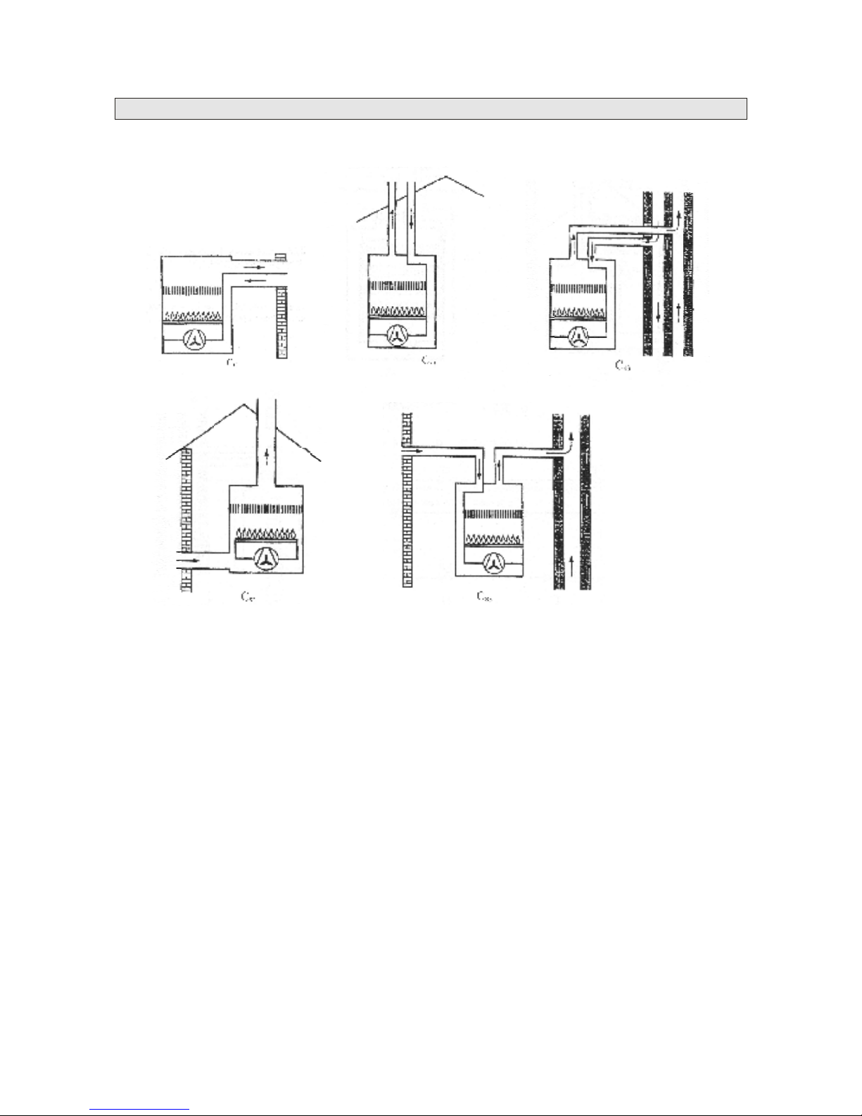
ATTACKKT,KSTboilersareapprovedbythestandardSTNEN483forthetypesC13,
C33,C43,C53,C83.
C13-typehorizontalcoaxialtype,wastegasoutletandairintakeareinequalpressure
conditions.
C33-typeverticalcoaxialtype,wastegasoutletandairintakeareinequalpressure
conditions.
C43-typedoubledtypeintoacommonflueshaft.
C53-typeseparatedairintakeandwastegasoutletwiththeintakethrough
thewallandwastegasexhaustthroughtheroof.Thistypemustnotbelocatedonthe
oppositewallsofthebuilding.
C83-typeseparatedairintakeandwastegasexhausttoaseparatedorcommonflue.
Waste-gasexhaustandcombustionaircomethroughdoublepipingdeliveredbytheboiler
producerwhichcanbeorderedinrequiredamountbytheproject(horizontalorvertical
exhaust)includingsealingcollars,roofreducingpiecesandsoon.
Basicrequirementsforwastegasexhaustfortheapplianceswithaburnerandforcedintake
ofcombustionairaresetbytechnicalrules.
–verticalpiping60/100:2,7m
–horizontalpiping60/100:3m
–whenadistributorandpipingforwastegasexhaustandairintakeof80mmareused,the
sumoflengthsofsinglecomponentsusedinthissystemmustnotbehigherthan10m
–each90°elbowinsertedshortensthelengthin0.75manda45°elbowshortensitin0.5m
–forverticalexhaustthrougharoofitisnecessarytouseacondensatecollector
Maximumlengthofwastegasexhaustpermittedbytheproducer:
Ø
Ø
Ø
Page 27

27
AccessoriesofwastegasexhaustofATTACKKT,KSTboilers
Accessoriesofcoaxialwastegasexhaustof60/100mm
CodeName
PR37Prolongingpiece1mD60/100paint
PR38Prolongingpiece0,5mD60/100paint
PR39Flue60/100paint
PR4090°elbowD60/100paint
PR4145°elbowD60/100paint
PR42elbowwithflange+serviceopeningD60/100
PR43verticalflange+serviceopeningD60/100
PR44terminalpipeD60/100paint
Accessoriesofwastegasexhaustandairsuctionof ø80mm:
CodeName
PR45Exhaustandsuctionpipe1mD80
PR46Elongationpiece1mD80
PR47Elongationpiece0,5mD80
PR4890°elbowD80O/M
PR4945°elbowD80O/M
PR50flueD80
PR51verticaldistributorD60/100D80/80
Ø
Page 28

28
Connectingaroomthermostat
Connectingacoaxialexhaustpipe.KT,KSTtype
Puttingtheboilerintooperation
Aroomthermostatisnotapartoftheboileraccesoriesbutcanbeconnectedintoaboiler
additionallybytherequestofacustomer.Thevoltageforswitchcontactsoftheroom
thermostatis230V/50Hz.Connectingoftheroomthermostatintotheboilerisillustrated
ontheconnectionchart.Connectingterminalsforthethermostatareinterconnectedbya
jumper.Afterconnectingtheroomthermostattotheterminals,thejumperisremoved.
Forthefunctionofaroomthermostatcanbeusedaroomregulatorwhichisconnectedtothe
OT1,OT2contactsoftheboiler.Thisregulatormustbecompatibleincommunicationwith
OPENTHERM(HoneywellCX51,CR11001...).ThevoltageontheOpenThermcontacts
OT1,OT2isunidirectional24V.
Combustionairsupplyandwastegasexhaustgothroughacoaxial90°elbowandacoaxial
1-m-longpipe.Theseorothernecessary90°and45°elboworelongationpiecesof0.5mand
1mcanbeboughtbyrequest.Themaximumlengthofcoaxialwastegasexhaustadmittedby
theproduceris3mhorizontallyand2.7mvertically,measuredfromtheboilertotheoutlet
onthefacadeortothebottomedgeoftheroofreducingpiece.Each90°elbowshortensthe
lengthin0.75manda45°elbowin0.5m.Thewholepressurelossofthepipingmustnotbe
biggerthan80Pa.Coaxialpipingmusthaveaslopeof3%totheboilerdownwards.
Puttingintooperation,checkingandsettingminimumandmaximumoutputoftheboileras
wellastherepairscanbecarriedoutonlybyfirmsauthorizedtothisandtrainedbythe
producer(listofthecontractservicepartnersisinthesupplement).
–checkwhethertheinstallationoftheboilerandaccessoriessuitstotheprojectandboiler
inspection
–checkthedeaerationoftheboilerandheatingsystem(theboltontheautomaticdeaerator
mustbereleased)
–checkthewaterpressureintheheatingsystem(minimumof1barinthecoldsystem)
–checkifthesafetyvalveisworking
–checktheconnectingtothegaspipelineaswellascontrolandsafetyelementsandtestthe
sealingofthegaspipelinefromthemainpipesealuptothefittingsintheboiler
–checkelectricsocketconnectingandelectroinstallationinspection
–checkthewastegasexhaust
–setupthegasvalveandtherightvalueofCO
–checkthefunctionofoperation
setappropriatepumpspeedandpressureintheheatingsystem
–testfunctionofballvalvespriortotheboiler
–getauseracquaintedwiththeboilerattendancewhichisconfirmedbytheuser´ssignature
ontheletterofguarantee
–writedownhavingputtheboilerintooperationtotheletterofguaranteeandinstructions
foruse
Dutiesofaserviceworkerwhenputtingtheboilerintooperation:
2
Page 29
29
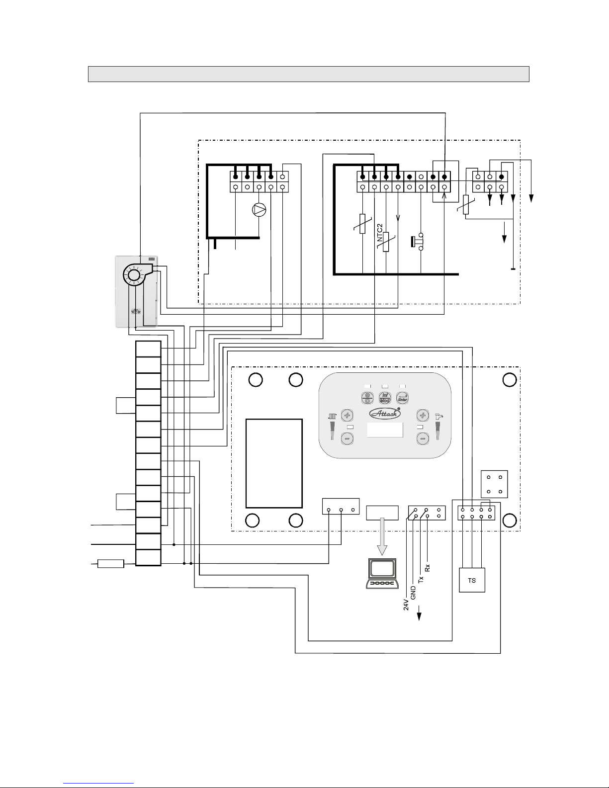
ChartofATTACKKTwiring
X1X12X11
N L
GND
X4
MMI
Rx
HL
1
4
361
9
8
16
1
6
5
10
P
CVBC
MMIDISPLAY
GND
PWM
TACHO
X1
X5X4
X2
X3
N
FS
24V
Trafo
L
X11
CVBC
T2
T1
PE
N
L
S4
S3
OT2
OT1
S2
L
N
R
PE
N
L
L
N
PE
230V/50Hz
2A
THERMOSTAT
JUMPER
FAN
NTC1
GND
Tx
S1
PC
2,2k
Jumper
Resistor
Ω
HL-emergencythermostat
FS-fluesensor
NTC1-Sensoroutletheatingwater
NTC2-Sensorreturnheatingwater
P-circulationpump
Fan
TS-pressuresensor
S1,S2-contactsofoutsidethermalsensor
OT1,OT2-contactsoftheOPENTHERMregulator
S3,S4-thermalsensorofhotwater
L,N,R-contactsofthree-wayvalveofhotwater230V
Page 30
30
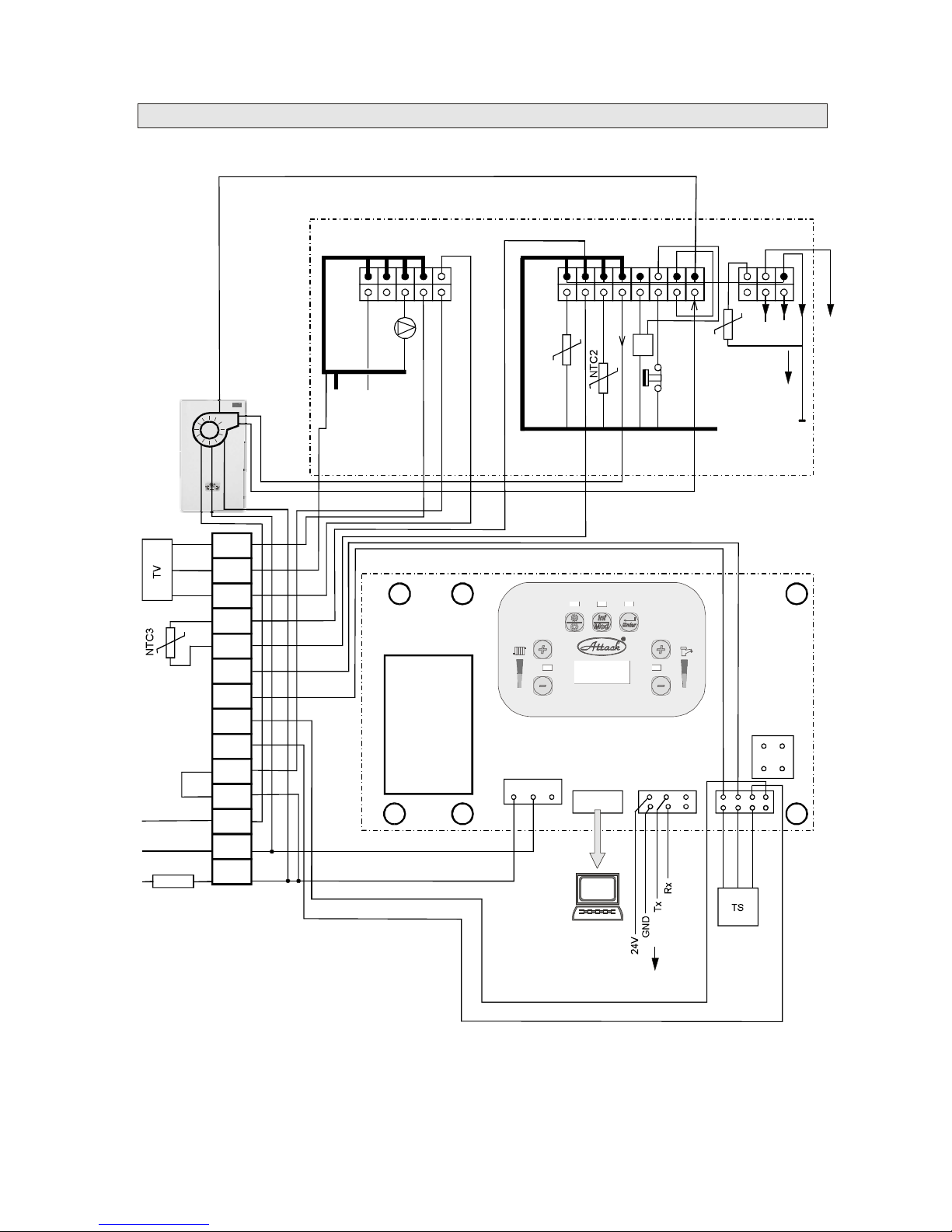
ChartofATTACKKSTwiring
X1X12X11
N L
GND
X4
MMI
Rx
HL
1
4
361
9
8
16
1
6
5
10
P
CVBC
MMIDISPLAY
GND
PWM
TACHO
X1
X5X4
X2
X3
N
FS
24V
Trafo
L
X11
CVBC
T2
T1
PE
N
L
S4
S3
OT2
OT1
S2
L
N
R
PE
N
L
L
N
PE
230V/50Hz
2A
THERMOSTAT
JUMPER
FAN
NTC1
GND
Tx
S1
PC
SP
GND
HL-emergencythermostat
FS-fluesensor
NTC1-Sensoroutletheatingwater
NTC2-Sensorreturnheatingwater
P-circulationpump
Fan
TS-pressuresensor
S1,S2-contactsofoutsidethermalsensor
OT1,OT2-contactsoftheOPENTHERMregulator
S3,S4-thermalsensorofhotwater
L,N,R-contactsofthree-wayvalveofhotwater230V
NTC3-sensoroftemperatureofhotwater
TV-driveofthethree-wayvalve
SP-sensorofhotwaterpassage
Page 31
31
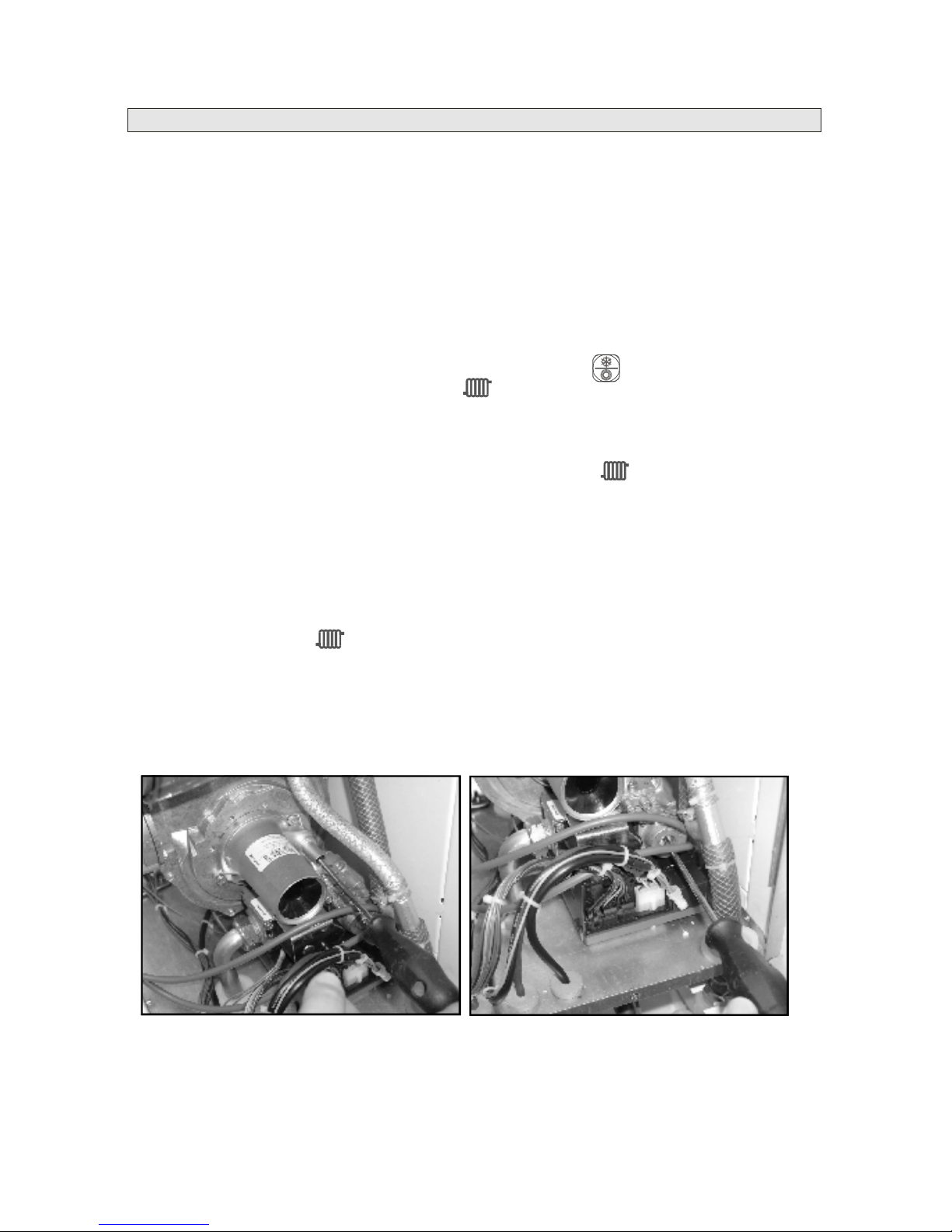
Setting-upagasvalve
Modulationoutputoftheboilerisfactorysetupandsuitstominimumaswellasmaximum
rotationsofthefan.BecauseoftherightworkingoftheboileritisnecessarytocheckCO
emisionsinwastegasformaximumandminimumoutputoftheboiler.
Howtocheckandsetup:
–turntheboileronwiththehelpofacableintoelectricalnetwork
–dismantlethefrontcoverandthecoverofclosingchamber
–checkthegaspressureintheinletbyrelasingthescrewofinletpressurecontrol.The
boilerisadjustedtoconnectingpressureofnaturalgasof20mbar.Afterchecking,tighten
thescrewup
–installtheprobeofwastegasanalyzerintothepipeofwastegasexhaust
–startthetestingmodeoftheboilerbypressingthebutton_______forlongerthan3
seconds.Withthe+/buttonsatthesymbol______setupthevalueof99correspondingto
maximumoutputoftheboiler
–turningthescrewwithaflatscrewdriversetupthevalueofCOto8.7%.Whenturningthe
screwclockwise,thevalueislowered(fig.No1)
–afterreachingthisvalue,withthebuttons+/atthesymbol_______setupthevalueof00
correspondingtominimumoutputoftheboiler
–turningthescrewoftheregulatorsetupthevalueofCOinwastegasto8.7%(fig.No2).
Whenturningthescrewclockwise,thevalueisincreased
–
–AfterstabilizingCOemisionsat8.7%,setupthevalueof99againwiththehelpof+/
buttonsatthesymbol_______andcheckwhetherthesetupvaluehasnotchanged
–Ifthereisachange,thevaluemustbecorrected.
Aftersettingupitisnecessarytomountthedismantledpartsonagain.
Fig.1SettingupCOformax.outputFig.2SettingupCOformin.output
2
2
2
2
22
Whenadjustingthescrewontheregulator,itisnecessarytousetheoriginal
screwdriverTORXTX40.Otherwisethescrewcanbedamagedandthereisno
guaranteeforthiskindofdamage
Ifthegasvalueissetupcorrectly,thevalueofCOformaximumaswellasminimum
outputisthesame,8.7%,andthisvaluecannotbechangedduring1minuteafter
repeatedcontrolformaximumandminimumoutputoftheboiler.
2
Page 32
32
Othersetting-up
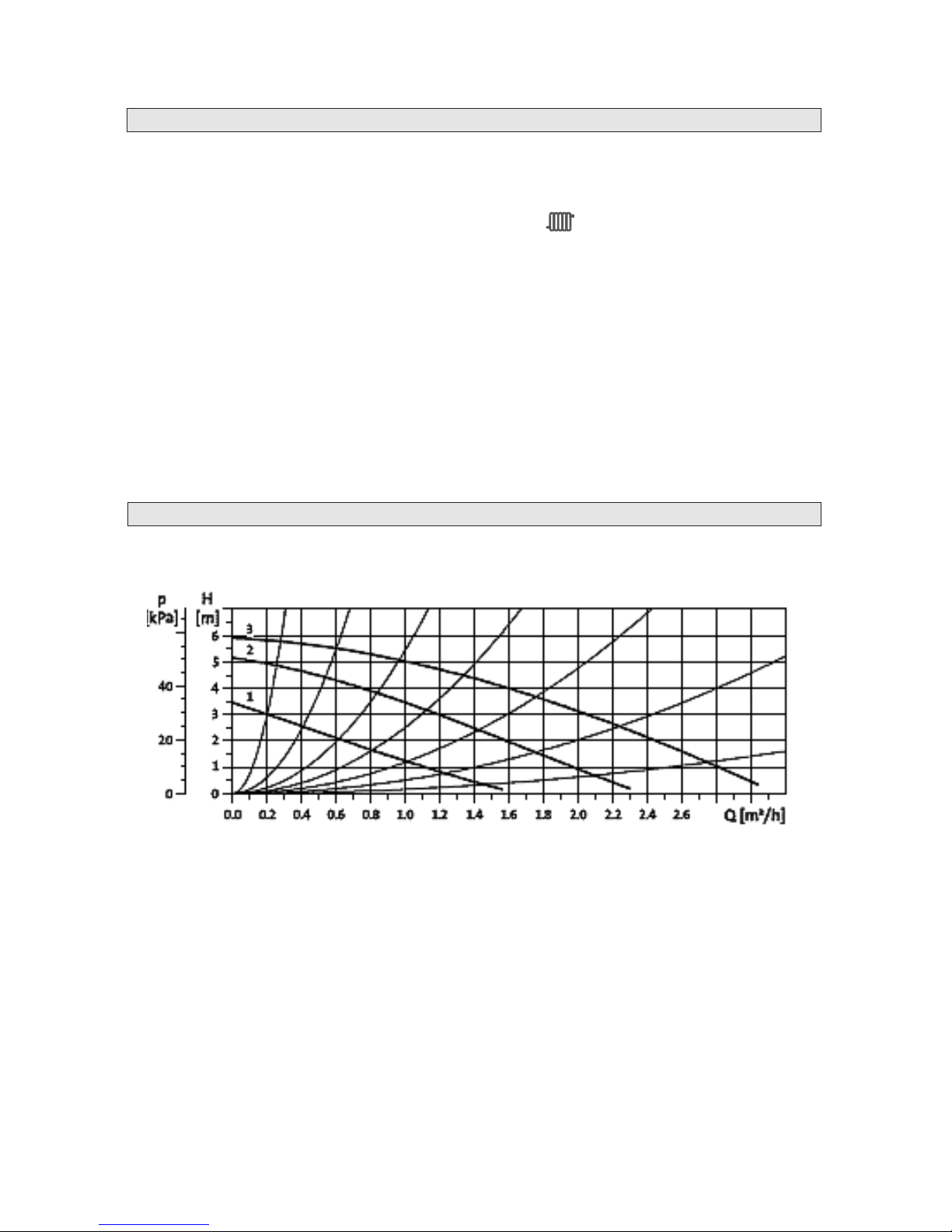
Characteristicsofcirculationpump
Maximumoutputoftheboiler
Installation
mode
Run-outofthepump
Startingoutput
Maximumoutputoftheboilercanbesetupintheinstallationmode(seechapter
,paramater14).Bythebuttons+/atthesymbol______setupanewmaximumoutput
oftheboilerinpercentageofmaximumboileroutputset-upinproduction.
Setting-upcanbefoundunderparameter12ofinstallationmode.Timeofrun-outisset-up
inseconds.
Startingoutputissetupbyparameter12oftheinstallationmodeandisdeterminedby
percentageofmaximumboileroutput.
Page 33

Notes:
33
Page 34

34
Notes:
Page 35
35
RECORDONPUTTINGTHEBOILERTOOPERATION
Boilertype:...........................................................................
Boileroutput:......................................................................
ProductionNo.....................................................................
Dateofputtingtooperation:.............................................
Servicecompany:...............................................................
Date:...............................................................................
Date:.............................................................................
Date:.............................................................................
Stamp,signature
Stamp,signature
Stamp,signature
Stamp,signature
Obligatoryserviceexaminationafterthe1styearofoperation
Obligatoryserviceexaminationafterthe2ndyearofoperation
Obligatoryserviceexaminationafterthe3rdyearofoperation
Page 36
N
SKCZATCHDKESFIFRGBGRIEITNLNOPTSE
Countryoftheappliancedelivery :
Producer:
Tel:043/4003101
Fax:043/4003106
E-mail:[email protected]
http: www.attack-sro.sk
ATTACK,s.r.o.
DielenskáKružná5
03861Vrútky
SLOVENSKO
KTKST
DOCUMENTontestingandcompletness
ofATTACKKT,KSTgasboiler
Boileroutput:7-25kW
BoilerproductionNo.:
Theproductdeliveredwiththiscertificatesuitstotechnical
standardsandtechnicalconditions.
Theproductwasmanufacturedbyitsdrawingdesigninrequested
qualityandisapprovedbyTECHNICALINSTITUTEFOR
TESTINGSKTC-104inPieš anyundertheNo.ofcertificate
512990027.
Technicalinspection
InVrútky,date:..................................................................................
Stampandsignatureofthefinalinspection:.....................................
 Loading...