


Operating instructions
Rota – Disc*
Corn header
Carl Geringhoff – Vertriebsgesellschaft mbH & Co. KG
Gersteinstraße 18, D – 59227 Ahlen
Tel. ++49-2382-9814-0, Fax ++49-2382-981440
E –BA-RD-03
E-Mail: info@geringhoff.de Internet: www.geringhoff.de

Content
General
Certificate of conformity EC 02 / 000
General safety arrangements 01 / 020
Introduction 01 / 000
To the customer 01 / 010
Warning label (pictograms) 01 / 030
Corn header
Contrate gearing speed change 09 / 600
Couplers between the stripping plates 09 / 640
Corn header to mount 09 / 120
Corn header drive 09 / 160
Corn header to unpack 09 / 000
Cross belt auger / feeding 09 / 720
Cut-off block
Divider noses to mount 09 / 320
Drive coupler folding corn headers 09 / 280
Gathering chains 09 / 520
Gearing and oil control 09 / 560
Hydraulic connections to mount 09 / 200
Hydraulic function of folding corn headers 09 / 240
Mounting arrangements on combine 09 / 080
Operation and function of monitor 09 / 440
Overload protections and sliding clutches 09 / 800
Stripping plate adjustment 09 / 480
Trial run 09 / 680
Weights 09 / 040
Rota Disc*
Knife disk shaft 10 / 100
Stripping rotors 10 / 200
Stubble cutter / stripper 10 / 000
Maintenance and Care
Maintenance and care 10 / 300
Help in case of malfunctions
Cross belt auger 10 / 915
Drive 10 / 905
Hydraulics 10 / 900
Stripping unit 10 / 910
Special equipment
Corn ear saver 35 / 050
Change speed gear 35 / 010
Change speed gear 35 / 005
Lodged maize augers
Sunflower harvester 35 / 000
Special tools
Chain tension tool 36 / 000
Starting torque for screws 36 / 100
Puller for rotor bearing 36 / 000
Wiring diagrams etc.
Wiring diagram combine lighting 36 / 500
Wiring diagram hydraulics folding headers 36 / 300
Corn header
10 / 210
00-001

Introduction
These operating instructions describe the most
essential working steps for a safe handling and use
of the Geringhoff products.
Read these instructions and observe the safety
notes.
A regular maintenance and care will help to keep
the value of the product and to ensure a troublefree use over many years to your benefit.
Tell us about your experience made with the
machine to enable us to put it into practice. The
partnership with our customers is very important to
us and will contribute to our common success.
01 / 000

To the customer
01 / 010
We thank you for the confidence placed in us on
the purchase of a Geringhoff product.
Hereunder you’ll find some important information
for the use of these operating instructions:
• When using the operating instructions, we
recommend using also the spare part
catalogue for gaining an in-depth
understanding of essential details.
• Note the most important data of your
machine in the fields provided. That makes
it easier to you answering the questions of
your supplier.
Machine no.:_______________________
Machine type.:_______________________
Year of construction:__________________
Row distance:_____________________
Working width/ Number of row units: _____
Combine type.:___________________
• The series no. is on the typeplate left on
the supporting frame.
• The operating instructions contain the
international standard SI-measures.
• Right and left means always towards travel
and/or working direction.
• If you are in need for spare parts, keep the
required data available and get in touch
with your dealer.
• Do only us original Geringhoff spare
parts.
• Send the completed consignment note
directly to the manufacturer. This
information is very important for potential
guarantee claims. Failing which, these
potential claims cannot be handled.
• Do not make any modifications on
important, load-bearing and safety-relevant
elements. The manufacturer does not
assume any guarantee for damages
resultant therefrom.

General safety arrangements
To prevent accidents, follow strictly these
operating instructions and warning notes on
the
machine.
Before starting the machine, check it for operational
dependability and traffic safety!
Apart from these operating instructions, follow also the
current safety instructions!
The warning signs and labels give important notes for
the safe operation of the machine and serve to your
and the health of others!
Prior to starting the works, make yourself familiar with
all operating elements and functions.
Check the driving characteristics, steering and braking
behaviour.
No riders unless sitting on the provided places.
When working on the machine, the provided supporting
devices must be used.
Admissible axle loads and total weight must absolutely
be observed.
Before the start-up, all guards and maintenance holes
to close.
Whilst the machine is running, keep off the dangerous
area.
Maintenance and repairing works to be performed only
with Diesel motor cut off.
On public roads the legal provisions to observe.
All machines have a valid ABE or EBE governing the
road transport licensing regulations.
If required, additional headlights for the road transport
to mount.
(see road transport licensing regulations)
The instructions of the combine manufacturer for the
operation with headers to follow.
01 / 020

Warning label (pictograms)
ISO 11684
Prior to performing maintenance and repairing
works, the motor to turn off and the key to withdraw! It’s only allowed to go into the dangerous zone
when the lifting cylinder safety is put in!
Keep off the dangerous zone between During the operation guards must not
header and machine! be opened or removed!
Whilst motor is running, guards never to Whilst the motor is running, guards must not be
open or remove! opened or removed!
Keep a sufficient safety distance to the header. Never go into the slewing range of
Prior to maintenance works or clearing of cloggings the machine!
header to switch off, motor to stop and key to
withdraw!
01 / 030

02 / 000
02 / 000
EG-Konformitätserklärung
EG-Konformitätserklärung

Rota – Disc* corn header
Rota – Disc*
We reserve the right of making modifications
for the sake of progress.
Sizes and weights are approximate values and refer each to
the standard versions of the different header types.
Due to the great number of header models and combines
this list cannot show all the different illustrated variants.
For this reason, we hope you will understrand the general
sense of the wordings, which requires a sufficient basic
knowledge of the carrier machine.
RD / 000

Corn header to unpack
Scope of supply / state at time of supply
Subject to model and type the header can be supplied in
horizontal position or upright on a shipping crate.
Each consignment is accompanied by a detailed and typereferred packing list.
Packages attached to the header to remove.
Check the scope of supply!
Check the supplied row distance!
Ensure the safe standing of the
machine!
Remove the shipping crate
Extend the supports (S). Move the hoist to the bottom side
of the header.
Suitable chains or belts to attach to the drawbar eyes (W),
slightly to lift and hoist slowly to move away from the
header.
Header carefully to lower considering the tilting angle.
Use hoist, which is strong enough!
Do not go into the dangerous zone!
Follow the instructions for hoists!
Remove screws (B) and shipping crate.
Further use of the trestle
The trestle (T) is recommended to be stored for a later use.
Possible after-season and service works are to be
performed easier with the machine standing in upright
position.
Folding corn headers to lift by crane
Folding headers are possibly supplied without shipping
crate (T).
For the transport with hoists only provided eyes (L) and
location on the front transport angle (S) to be used.
If required, transport protection to remount.
Before mounting the header to the combine, transport
protection to remove (S).
Protection to remove only when the header stands on firm
ground.
09 / 000

Corn header to unpack
A
Transport protection folding corn headers
part from the transport protection as shown in picture
N 003, folding corn headers from 8 rows are fitted with an
additional protection (B) on the frame.
Bolts (B) not to remove before
definite placing down of the
header and removing of the hoist.
When using the hoist again, locking bolt (B) must be put in
before.
Corn header Approximate weight
in kg
4-rows 1290
5-rows 1640
6-rows 1975
6-rows (folding) 2250
7-rows (folding) 2400
8-rows 2520
8-rows (folding) 3025
Take a hoist, which is strong enough
The weight of the different header models to be learnt from
the opposite table.
Follow the instructions for the use of hoists!
The exact weight of the different headers is
indicated well visible on the typeplate of
each machine!
9-rows 2750
9-rows (folding) 3250
12-rows 3650
12-rows (folding) 4150
09 / 040

Assembly preparations on the combine
A
leuchten des M╠hdreschers
und des Frontschutzes m¤s-
Gegr¤ndet 1880
f¤r alle Md Typen
Front protection on gathering channel
The standard front protection (S) on top of the feeding
chain and the stripping angles (A) on the gathering
channel front are to be dismounted.
The corn header itself is fitted with a special front
protection.
When working on the combine, the
Diesel motor must be turned off!
Assembly preparations gathering channel
The feeding chain, its tension and the distance to the
channel bottom is to be adjusted according to the
instructions of the manufacturer.
(See combine manual)
Prior to the first mounting of the header, the anti-lowering
device of the gathering channel to check. Never to
perform works on the header without using this device.
On all service works on the mounted
header, lowering lock to activate!
Additional headlights
Some combine models require to mount additional
headlights for the road travel, see the scope of supply of
the header.
wiring diagram is enclosed to the headlight set. A
position switch must be used for changing between
standard and additional headlights!
Instructions of the TÜV-expertise to observe!
General terminal connecting diagram on page 36 / 500
Monitor
Display unit (M) to mount well readable but without visual
obstruction on top of the fittings.
The 12 V current is supplied independent of the ignition
lock via the plug (Z). (fuse max. 10 Amp.).
Connecting cable (S) right below with seal (T) to lead out
of the cabin bottom. Ensure that the cable is long enough
outside the cabin.
The monitor reads both the speed of the header and the
position of the stripping plates (P) via a changing number
of diodes.
09 / 080

Mounting of the corn header
Adaptation to the combine
The corn header is to be placed down on the supports (C).
Check the correctness of the adaptation parts. Fur further
information, see spare part catalogue 3061000 from
picture table 60/..
Combine to move to the header.
Header with the gathering channel to lift.
Correct seat of the adaptation parts (A) to check.
Persons are not allowed to stay
between comb between combine
and header during the mounting
process.
Corn header to lock on gathering channel
Corn header to secure against
unwanted lowering by u lowering!
Use locking mechanism
on the hydraulic cylinders!
The header (R) to be mounted to the points and devices
of the combines as provided.
Corn headers always slowly to lower to the ground to
keep
unwanted forces away from the locking.
Follow the instructions of the combine manufacturer!
Additional lifting cylinder
Subject to the size and weight of the corn header, one or
two additional hydraulic cylinders (Z) may be required.
The combine manufacturer holds the corresponding kits
ready.
Subject to the design of the corn header and carrying
capacity of the different combines, the steering axle may
require using additional weights and the tires being filled
with water.
Follow the instructions of the combine manufacturer and
TÜV-expertise
Additional counterweights
Subject to the weight of the mounted corn header,
additional loading weights may be required for being
mounted to the steering axle of the combine.
The dimensions of these additional weights are to be
learnt from the road permit, combine manual or TÜVexpertise of the corn header.
The road transport licensing
roads must regulations must
absolutely be followed.
09 / 120

Corn header drive
A
A
Drive with PTO-shaft
Unfolding corn heads are driven by a simple PTO-shaft on
the right side.
Subject to the combine models, they can also be driven on
the left side, e.g. machines > 6 rows.
PTO-shaft protection to prevent from turning via chain (K).
If the combine is fitted with a pivoting shield, overlapping to
be checked in extended state.
Protective devices (S) to be checked
prior to start-up. Do not open or
remove them during operation.
Folding headers with PTO-shaft coupler
Check the PTO-shaft between coupler and channel
connection for sufficient overlapping. If required, pivoting
shield to actuate.
The heel compensation of some
models requires to be blocked.
On RD600F / RD800FB e.g. to John Deere series 20... /
22... + WTS / STS / CTS with PTO-shaft coupler, the
pivoting shield must be blocked ( follow the instructions).
Hillside combines cannot be operated with automatic
PTO-shaft coupler.
Drive for hillside combines
ll hillside combines are directly driven by PTO-shafts (W)
to be slipped on by hand.
Certain combine-header combinations require wide angle
or even special PTO-shafts.
Instructions absolutely to follow and PTO-shaft design to
consider.
Prior to start up, check pivoting
range and PTO-shaft length. Check
for sufficient overlapping.
The fastening (T) of the PTO-shaft is for transport.
Use of the pivoting shield (heel compensation)
On principle, the pivoting shield of the combine can be
used combined with the majority of the corn headers
without any limitation, unless otherwise specified.
The instructions of the combine manufacturer to follow!
PTO-shaft length to check in all positions.
If required, special locks (R) to mount to upper adapter
frame and secure.
lways trial run to conduct!
Instructions for PTO-shaft drives to observe!
09 / 160

Hydraulic connections
Multicoupler
If the combine is fitted with a multicoupler (optional), the
header should be fitted likewise.
The suitable coupler (optional) can be added to the supply.
The operation to be made according to the instructions of
the combine manufacturer.
When checking the functions, keep off
the dangerous zone.
Tightness to check!
In case of leakages the conditions for
environmental protection to follow !
Connection via control valve coupler
Some combine makes require using a control valve
coupler (M) for connecting the header.
The respective headers are fitted accordingly as
standard.
The operation to be made according to the instructions of
the combine manufacturer.
When checking the functions, keep off
the dangerous zone.
Tightness to check!
In case of leakages the conditions for
environmental protection to follow
!
Connection via simple screw and/or slip-on
couplers
If only simple slip-on and/or screw couplings are available,
first double and simple-acting lines are to mark.
The simple-acting line is to connect to the line of the
stripping plate adjustment.
The double-acting lines serve to the control of the folding
process of the respective headers.
Establish a safe connection to allow the oil flowing !
Lines to mark and always immediately to connect so that
the working purpose remains unchanged!
Hydraulic actuation of the folding process
Reel:
“ Lifting and lowering ” = stripping plates
closed ”
Reel horizontal adjustment: (optional)
“ forward and backward ” = folding process “ open and
closed ”
When checking the functions, keep
off the dangerous zone.
Tightness to check!
In case of leakages the conditions for
environmental protection to follow.
“ open and
09 / 200
Hydraulic functions of folding corn headers
Folding process (from transport in working position)
Reel horizontal adjustment of the combine to actuate until
the header has reached its working position.
Keep off the dangerous zone!
Keep off the working range of the
header! header!
Valve actuation not to finish until 10 seconds after complete
closing of the cover shields (to assure the locking function).
Machine to run idle to get the drive coupler engaged.
Locking
Once the header is completely open in working position,
the locking (B) is automatically activated.
If the header is not completely open in working position, to
troubleshoot.
(see help in case of malfunctions, page 10 / 900)
There are possibly foreign substances hindering the
function.
Bolt (B) must completely extend in locked state.
Check drive coupler! Cams are spring-loaded and turn off
unless cam and opening in driving plate are not in line!
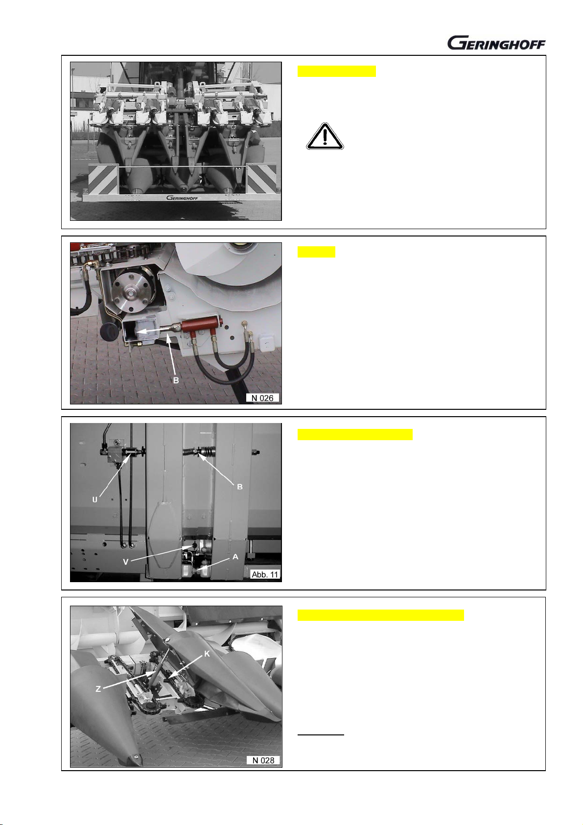
Control valve for locking
The locking (V) is triggered by the valve (U) and closes
only if the header has really reached its working position.
If the locking is not activated despite of sitting closely on
the stop screws (A), on-off valve (U) to readjust with screw
(B), if required!
If required, stop screws on the bottom frame and locking
bolts (V) to readjust.
Automatically closing cover shields
Cover shields (A) close only after complete extension of the
locking bolt.
Failing which, to troubleshoot.
Factory adjustment has been checked. Corrections are in
general not required.
Folding process is not finished until the cover shields are
completely closed.
Attention!
Machine not to run with opened shields. Hydraulic cylinder
(Z) would get in contact with the gathering chain.
09 / 240

Drive coupler folding headers
y
A
Drive coupler folding headers
The drive coupler, if any, ensures an automatic coupling of
the PTO-shaft drive.
Prior to start-up and then in regular intervals the correct
osition of the coupling halfs to check. p
Check the protective devices (S) for correct fitting.
Machine always to let idle.
Persons to keep off the dangerous
zone!
Drive coupler 6-row folding headers
The coupling half mounted to the folding element is
adjusted only via the protective tube (R).
If the coupling halves must be readjusted, screws (S) to
loosen and protective tube to displace accordingly.
Parallel fitting of the coupling halves absolutely to assure.
The coupling halves to axially regulate only via spacers (Z)
below the bearing.
Correct fitting of the protective ring (G) to ensure.
Header with drive couplers on both sides
From a certain number of rows the headers are fitted with a
both-sided drive.
If the coupling halves require an axial regulation, spacers
(Z) only to use on the marked positions.
The radial adjustment is made on the bearing points b
displacing the bearings into the bores provided.
The parallel fitting of the coupling halves absolutely to
ensure.
Maintenance and care
Coupling washers (S + B + K) to be slightly greased in
regular intervals.
Sliding parts of the respective coupling halfs once to
dismount prior to start working and sliding parts to grease.
xial fastening screw carefully to tighten with standard
torque.
Header drive not to set into operation
if the header is in collapsed state.
Risk of accident on the coupling halfs!
09 / 280

Divider noses to mount
Selection of the divider noses for mounting
Divider noses with bore (D)
The supplied center divider noses differ only by a bore
(D) about 18 mm Ø if the header has been supplied with a
transport protection.
These center divider noses are to mount right and left (T)
from the center (M) for receiving the transport protection.
Corn header to lift and secure via
support on the lifting cylinders against
unwanted lowering!
Mounting of the center divider noses
Shield to open by throwing over the lever (H) and slightly to
press upwards from the centerings to the stop of the gas
pressure spring.
Shields may jump upwards by gas
pressure cylinder!
Tube (R) to remove once unscrewed the axial screwing (S).
Tube to put in provided bore of the divider nose and shield.
Screwing to tighten.
Divider nose to lift and setting bar (E) to hang into the
support (A). Safety bolt (B) to mount and secure by cotter
pin.
Shield strongly to press down for closing and to check that
locking pin hooks in. Via lever (H) shield to close with
moderate prestress. If required, locking hook to readjust.
Mounting of outer divider
The same procedures as with the center divider noses.
Risk of bruising when mounting
shields and divider noses !
The divider noses are adjusted via the screw (E).
09 / 320

Divider noses to mount
A
The center divider noses to mount to the shields
Only possible with the hydraulic connection already mounted.
Start folding process. If folding shields are open, procedure
to stop.
Motor to turn off !
Corn header to secure against
unwanted lowering!
Mounting procedure of the divider noses is the same as for
the other center noses.
The divider noses are adjusted via the screw (E).
Adjustment of the divider noses
Protection against lowering to remove.
Header to lower to a ground distance of about 10 cm on an
even surface.
Divider noses with screw (E) to adjust such that their
distance to the ground is 2 cm (normal adjustment).
On the harvest of lodged maize and if the combine sinks
into the deep ground, the noses are to lower deeper.
Attention!
In case of an extremely lower adjustment, ensure that the
divider noses don’t get in touch with the gathering chains!
Mounting of the increased shield
For transport size and package reasons the
increased side shield is supplied unpacked.
It is mounted to the outer bodywork into the provided
threaded bores (G).
Attention!
ll screws of the plastic parts normally to tighten to prevent
the bores from being damaged.
The harvest can be made on option even without these
Bores to drill for transport protection
If divider noses have been mixed up on assembly or
supply, the required bores can be drilled into the both
center divider noses on the site.
Directly behind the divider nose top plate an 18 mm Ø bore
to drill only into the upper plastic surface.
The respective center divider noses are selected according
to the specifications of the transport protection or to picture
N 017 on page 09 / 320.
09 / 360

Road transport
A
Front protection
Unfolding headers up to a transport width of 3,0 m are
fitted with an unlighted transport protection.
ll foldable headers up to a transport width of 3,3 m are
fitted with a lighted transport protection.
The connection is made via a standard socket which, if
not available, must be mounted on or below the driver
stand.
The outer unfolding center divider noses are provided
with bores for locking the transport protection.
(see page: divider noses to mount, page 09 / 320)
Front protection with lighting connection
on multicoupler and/or control valve unit
In certain combine makes the lighting connection for the
front protection is integrated into the general supply line
(M) to the header.
- The front connection is then connected to the
socket (E).
- If required, the front protection is connected via
another individual connection.
Instructions of the combine manufacturer to follow!
Transport on public roads
It’s not allowed to transport the corn header on public
roads without transport protection.
The maximum admissible height of the slewing arm of the
ejecting channel on the transport on public roads is about
0,45 m as measured on the front protection (H) and is
determined for each machine in the separate licensing
documents.
Road transport licensing and
TÜV-regulations as well as instructions
of the combine manufacturer absolutely
m to observe.
A TÜV-expertise is enclosed to
each machine.
09 / 400

Operation and function of monitor
Monitor to connect to the header
Plug-type connector of the monitor cable coming from the
driver cabin to connect right with the header coupler.
Current supply to activate as described on page 09 / 080
Speed indication on monitor reads „ O “.
If the machine is running on operational conditions, a value
of about 720 - 750 r/min is indicated.
The speed indication allows to reliably evaluate the state
and load of the combine against the header.
Dropping speeds signal either an insufficient belt tension or
overload of the combine drive.
Stripping plate adjustment
Subject to the position of the stripping plates, a certain
number of green (G), yellow (Y) or red (R) diodes light up.
The more the stripping plates are open, the more diodes
are lighting up.
The number of the flashing diodes is only to be seen
on the monitor. Before the start-up, the proportion of
the flashing diodes to the position of the stripping
plates as a function of the harvest conditions is to be
determined.
Prior to checking, Diesel motor
to turn off! Keep your hands off the
stripping plates!
Recording tachometer
The recording tachometer (S) is located between two rows
on the drive connection claw of the Centaflex-coupler.
The distance between the magnetic switch (S) to the
magnet (M) and/or claw should at least be 1,5 mm and at
max. 2,5 mm.
Rheostat of stripping plate adjustment
The rheostat (A) and the slider (W) should be cleaned in
regular intervals.
Via the axial adjustment of the spindle (G) and by
displacing the position of the rheostat (A), the indication of
the diodes allows individually to be changed.
Electric supply lines to be checked in regular intervals.
Prior to checking, Diesel motor to
turn off!
Header to be secured against
09 / 440

Stripping plate adjustment
j
A
Function and basic adjustment
The basic front adjustment is 20 mm and the rear one
23 mm in position „ narrow “. That means, the stripping
plates are pushed together as far as possible.
The wedge-shaped adjustment is of essence for the
function of the header.
These values are set via the screwed down stripping plate
(R) and the screws (K).
For the harvest, the stripping plates are operated
hydraulically via „reel to lift and lower“.
The average corn ear diameter is important for the setting
of the stripping plate distance. For this reason, the plates
for the harvest works should be opened as far as possible,
ust as far as to prevent cob losses.
Prior to checking, Diesel motor
to turn off!
Header to secure against unwanted
lowering!
Via the shifting cylinder (Z) the left stripping plates are
opened by the sliding bar (T) and lever (H). The plates are
closed again by one or several restoring springs.
The regulation of the uniform setting of all stripping plates
on the different rows is made by shifting the levers (H) on
the sliding bar (T).
Before going to make a readjustment, it is recommended to
check the basic adjustment „in front 20 mm, rear 23 mm“.
Stripping plate adjustment folding headers
The function and layout is identical to the unfolding
machines.
The stripping plates on the folding parts are actuated via
the spring-loaded sliding bar contact. Additional, right and
left differently mounted restoring springs open the plates
on activation of the folding process.
Pressure plates should well overlap.
djustment and setting to be made in working position and
adequate locking only.
Maintenance and care of the stripping plate
adjustment
Impurities are not to exclude. For that reason, at least once
the day the stripping plates (L) to open and close several
times to assure the free floating and to remove impurities.
Joints to oil every 100 h. Restoring springs to clean.
Once finished the harvest works, bearing (C) of the
adjustable stripping plate (L) to clean and to protect
against corrosion using adequate means.
Check that the cut-off block is centrically arranged in
central working position.
09 / 480

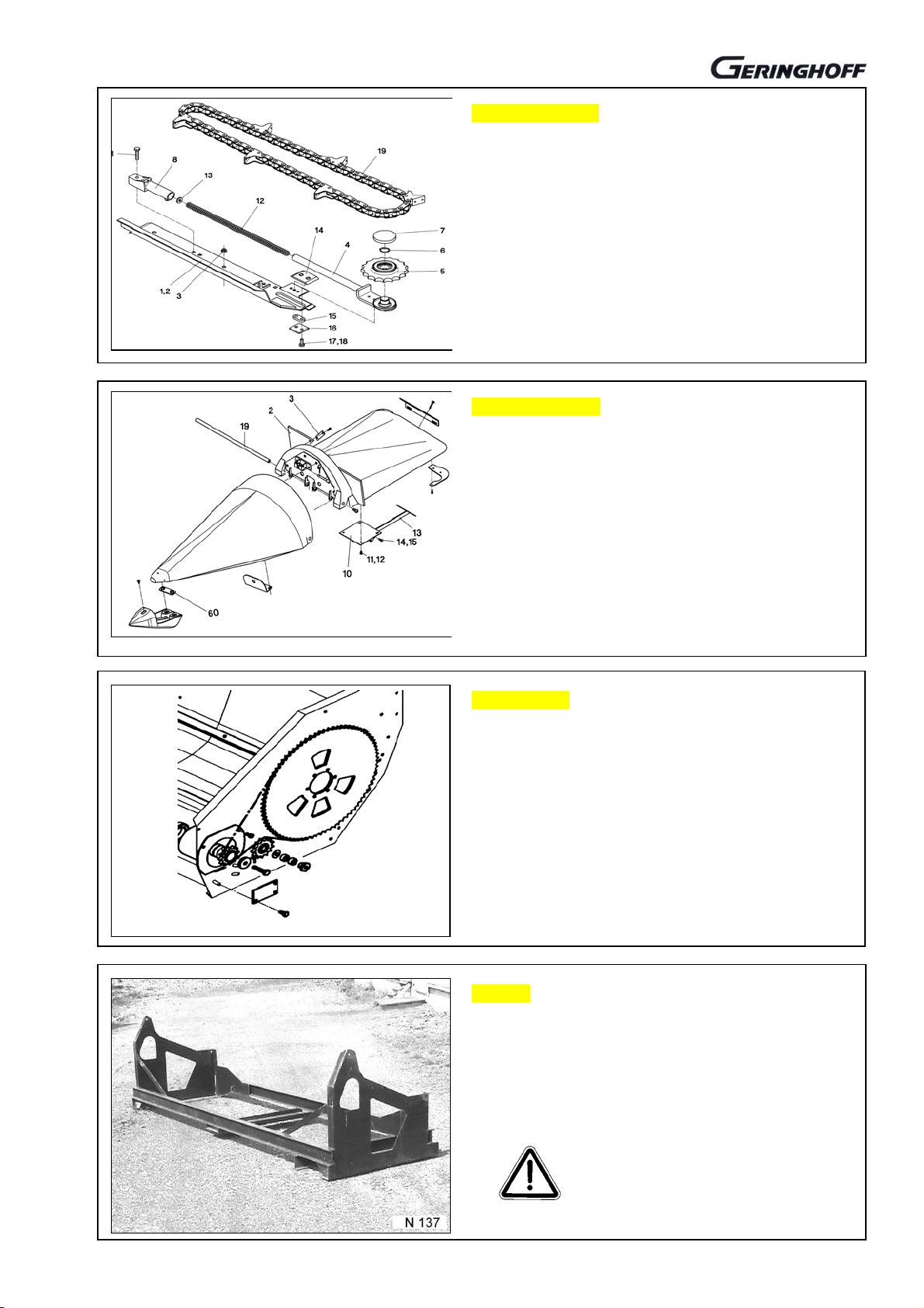
Gathering chains
A
A
Gathering chains
Special slipping wheels (R) are to secure the gathering
chains and to prevent the penetration of foreign substances.
The position of the gathering chain drivers (A) to each other
is permanently changing, even on normal harvest operation
by response of the slipping function.
When stating a chain elongation (ill. N 107), there is the
unique chance of shortening the chain by one outer and inner
link plate each (B). The shortening to be made in the area
(14) = 14 pces. link pin distance from driver to driver.
The plastic protective rings (O) beneath the slipping wheels
to be checked for good state.
Chain tensioner
The maintenance-free gathering chains are automatically
tensioned via constant spring pressure.
The preset chain tension is also to regulate the driving torque
of the gathering chain and thus the efficiency of the slipping
wheels.
When to change the gathering chains?
= 83 mm chain in new state
= 113 mm chain worn-out, replacement required.
Attention!
Consider also the wear of the frontal reversing wheels!
Dismounting of the gathering chains
The chains can be dismounted with ease by using a special
tool, spare part no.
501190 attached to the header.
Prior to working on the machine,
Diesel engine to turn off.
Special tool may jump back!
The gathering chains are recommended to be
changed once the year from right to left and
viceversa to ensure thus a uniform wear.
Frontal chain reversion to dismount
Tool for chain dismounting to place to pos. (B) as shown in
ill. N 058 and N 198 and to pull tight. Lever to secure under
hook (E).
The frontal reversing chain wheels to be dismounted in the
same way. Special tool to mount into bore (L). Lever to
secure under hook (E), then the fastening beneath the
reversing wheel to remove and tool slowly and carefully to
relieve.
Tool jumps back by !
spring pressure
Risk of accident!
09 / 520

Transmission – oil control (maintenance intervals)
g
g
Row unit transmission
Corn header to lift to a height of about
1 m to allow the lowering protection to
The oil level is controlled by a standard dip stick on the oil
filling plug.
Gauge position: Header lifted to about 1 m.
Filling level: 1,5 l gear oil SAE 90 (commercial quality)
Changing interval: 50 h from start-up, then once before
each harvest but at latest after 500 h.
Oil drain plug (not visible) is fitted with magnet, which must be
cleaned on each oil change.
engage. Turn of Diesel engine!
Angular transmission
Oil level control of angular gear via central gauge plug (K).
Filling level: 1,5 l gear oil SAE 90 (commercial quality)
to fill to the escape on gauge opening.
Changing interval: 50 h from start-up, then once before
each harvest but at latest after 300 h.
Oil drain plug (A) is fitted with magnet, which must be
cleaned on each oil change.
In folded state, exhauster (E) to be checked in regular
intervals.
Oil level to be checked in re
ular intervals!
Contrate gear transmission
Oil level control via gauge plug beneath gear center (K).
Filling level: 1,5 l gear oil SAE 90 (commercial quality)
To fill up to the escape on the gauge opening.
Changing interval: 50 h from start-up, then once before
each harvest but at latest after 200 h.
Oil drain plug (A) is fitted with magnet, which must be
cleaned on each oil change.
In folded state, exhauster (E) to be checked in
regular intervals.
Oil level to be checked in re
ular intervals!
Change speed gear 2, 3 or 5 gears (optional)
Oil level control via gauge plug (K).
Filling level: 1,5 l gear oil SAE 90 (commercial quality)
To fill up to the escape on the gauge opening.
Changing interval: 50 h from start-up, then once before
each harvest but at latest after 200 h.
Oil drain plug (A) is fitted with magnet, which must be
cleaned on each oil change.
In folded state, exhauster (E) to be checked in
regular intervals.
Oil level to be checked in regular intervals!
09 / 560

Contrate gearing speed change
Nominal speed is not reached
Unless reaching the nominal speed of the header of about
n = 720 -750 U/min., the speed can be corrected by
changing the contrate gear within the transmission (K).
First to check whether the speed of the combine on the
PTO-shaft connection (B) in question is in line with the
factory specifications.
On the transmission box is marked a number on the pos.
(Z) showing the teeth number of the contrate gear.
The following formula allows to calculate the speed:
Combine speed x teeth number of contrate gear / 32 = header
speed
Change of contrate gear
PTO-shafts (B+G) to remove.
Screws of the transmission fastening on the backside to
remove and the complete contrate gear transmission to
take off the header.
New contrate gear to get from the manufacturer or dealer.
Attention!
The contrate gears are available only in certain gradations.
If intermediate speeds are required or wanted, change
speed gear to be mounted (page 35 / 010).
Changed teeth number of the contrate gear to mark on the
transmission box!
Opening of the transmission
Transmission to put down horizontally to avoid oil losses.
Screws (6) to remove.
Box cover to loosen by knocking with an adequate tool and
to take off. Shaft (12) with bearing (11) is still in the cover
(5).
Shaft (12) to drive out of the box cover (5) in arrow
direction.
Screws (13) to remove and contrate gear (15) to replace.
Works to be performed by an expert only.
Contrate gear transmission to remount to the
header
Contrate gear transmission to mount to the provided place,
if required together with PTO-shafts.
Fastening screws slightly to tighten such as to allow the
transmission still to be aligned (see white line X).
Only original screw length (6) to use, since longer screws
would destroy the transmission housing.
Guards to mount and trial run to conduct. Check the speed!
Oil level to check.
09 / 600
Couplings between the row units
A
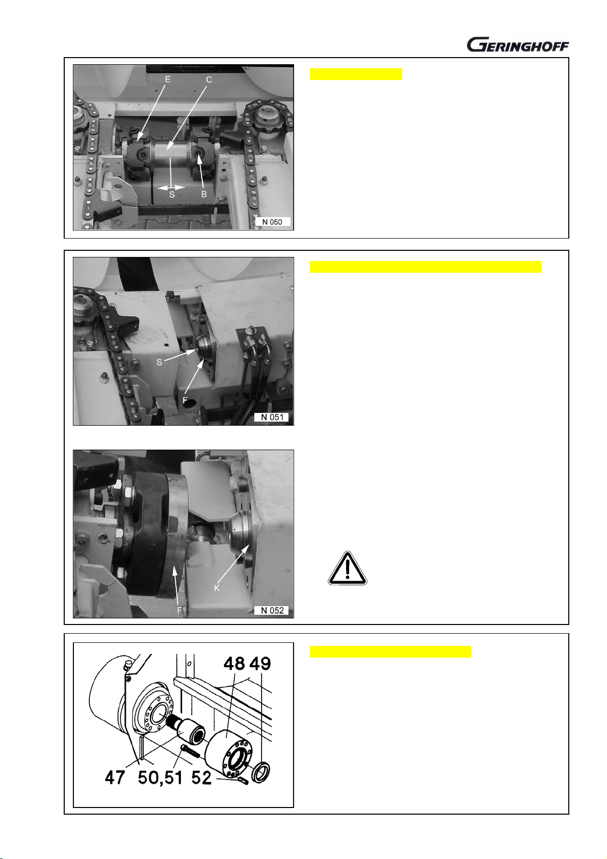
Centaflex-couplers
Centaflex-couplers (C) to be checked in regular intervals
for the state of the flexible elements (E) and engaging
dogs.
Worn parts to replace immediately.
xial clearance (S) of 2 mm for the center part (C)
absolutely to keep.
Hexagon socket screws (B) to tighten with 140 Nm.
Row unit drive connections on the folding parts
The axial movability of the coupling half (F) to be checked
in regular intervals by mounting lever to be pressed in.
If required, axial safety bolt (S) to unscrew, coupling half to
pull off, splined shaft section to clean and grease.
The parallel position of the cam plate (K) towards the
punched disk (F) to be checked in regular intervals with the
machine put out of operation and the coupler engaged.
Radial differences are to be compensated by
readjustments made on the pivot of the folding part
suspension.
Drive couplers to get engaged
only at minimum speeds.
Corn header with shaft extension (optional)
Corn headers with certain row distances can be fitted with
a shaft extension on the drive side.
Flange (48) and intermediate shaft (47) are arranged
between angular gear and the row unit gear.
The intermediate shaft needs no maintenance at all.
09 / 640

Trial run
A
First trial run
Corn header to lower near to the
ground. Keep off the dangerous zone.
All guards to close!
Machine first to let idle.
Check the smoothness of running.
In case of trouble turn off immediately!
Secure against unwanted lowering!
Troubleshoot!
Check the working speed on the monitor.
(n =720-750 r/min)
Reversing
ll modern combines are fitted with a standard reversing
device for the header drive.
This device for allowing the machine to reverse can be
used for cleaning during the operation of the header
without any limitation.
• Function to check
Test of the heeling compensation
Prior to start-up, the pivoting shield function of the combine
is to be checked combined with the corn header.
• PTO-shaft length and sufficient overlapping to
check!
• Slope steering to check
Keep off the dangerous zone whilst
the machine is running !
(optional)
09 / 680

Cross conveying auger/ Feeding
A
Conveying aids
The conveying aids (F) are mounted as standard on the
cross conveying auger.
On option, these conveying aids can be enclosed
unpacked and mounted on the site.
In the event of a not uniform feeding all over the combine
width, the conveying aid (size B) is to mount 40 mm
narrower than the inside gathering channel width is.
That means the size (B) must be 40 mm smaller than the
channel opening of the combine.
Feed opening of the corn header
Certain opening sizes of the header for all combine makes
and models are determined for the feeding to the gathering
channel of the combine.
The exact opening width to be learnt from the sketches in
the spare part catalogue from picture table 60/.. .
For standardization reasons, slight variations from the rated
size are allowed.
In particular when working on slopes a regular feeding is of
essence for the harvest material to be distributed evenly
within the machine.
Auger drive up to 6 row units
The auger is driven from the side opposite to the main
drive. The speed is subject to the main shaft of the header
and thus preset.
Chain tension to check in regular intervals, if required, to
readjust via the idler (S).
Chain to oil in regular intervals.
Protection box to clean in regular intervals.
Corn header never to operate without
guards mounted and closed!
Auger drive from 8 row units
The auger is driven from the feed shaft of the contrate gear
transmission and is not subject to the speed of the header.
Maintenance and care of the chain drive to be made via the
flap (K)
The chain tension is adjusted by shifting the tension lever
(S) downwards.
ll bearings of the cross conveying auger are maintenance-
free.
The bores (B) serve to fasten the contrate gear
transmission.
09 / 720

Cross conveying auger / Feeding
A
A
Sliding clutch cross conveying auger
ll auger drives are fitted with a maintenance-free and not
readjustable sliding clutch.
If the sliding clutch reacts, machine immediately to turn off
and troubleshoot.
Insufficient torque of the clutch cannot be decisive for the
response behaviour.
In case of overfeeding, the reversing device of the combine
allows for a refeeding.
Chain drive to grease and tension in regular intervals.
Driving clutch cross conveying auger
The coupling halfs (K) in the folding auger elements are
spring-loaded mounted on a splined shaft section engaging
automatically after the folding process.
xial spring load of the clutch (K) several times to be
checked during the harvest season by simple pressing in.
The screw joint of the bearing holders (L) serves to the
adjustment of the auger elements.
Once finished the setting works, the screws to remove.
Setting of the cross conveying auger
The cross auger is factory-mounted in ideal position and
not provided for being displaced.
Provided setting facilities serve only to the assembly of the
cross conveying auger.
Bearing holders (L) must in working position be parallel and
close to each other (max. 2 mm distance).
If the bearing holders (L) are too far from each other, the
corresponding auger element can be regulated by axial
displacement. For doing so, the locking ring of the
respective bearing to loosen.
Covering cap cross conveying auger
The height adjustment of the covering cap is made via the
screwing (S).
The distance between auger and cap should be as big as
possible to ensure a free passage of husks, leaf and even
stalk parts.
Prior to working on he corn header,
Diesel motor to turn off!
09 / 760

Overload protections and slipping clutches
A
A
Basic equipment of all headers
number of overload protections and slipping clutches are
provided for the safe operation of the machine.
If these devices respond, corn header
immediately to turn off!
Diesel motor of the combine also to
turn off and header to secure against
unwanted lowering!
Troubleshoot and trouble to rectify.
Never switch the header on and off to get it turning again.
Sliding clutch in the row unit gear
One maintenance-free and wear-poor cam clutch each (19)
is arranged within the gears.
If it responds, there is a trouble beside the normal
operational conditions.
Once stated that the foreign body did not cause the
response behaviour, the reversing device of the combine
allows the header to be turned backwards and to remove
sticking harvest material.
Clutch must not run hot!
Slipping wheels on the gathering chains
See also page 09 / 520
The special tooth form of the driving chain wheels (K)
combined with the automatically tensioned gathering
chains effect a well-balanced driving torque of the
gathering chain drive.
In case of overload or foreign bodies the driving chain
wheel turns within the gathering chain without moving it
ahead. That ensures that damages are prevented and
foreign bodies kept away from the combine.
Never to change the chain tension using inadequate tools.
Slipping clutch in the cross auger drive
not readjustable cam clutch is mounted on the drive side
of the auger shaft.
If it responds, there is a trouble beside the normal
operational conditions.
Once stated that the foreign body did not cause the
response behaviour, the reversing device of the combine
allows the header to be turned backwards and to remove
sticking harvest material.
09 / 800

Rota –Disc* Working angle adjustment
A
g
Working angle (basic position)
working angle of 27° is factory-set. If the combine is fitted
with larger or smaller tires than the series equipment, we
recommend checking the working angle. The same applies
also to crawlers.
The real angle is to be determined with ease by placing an
adjustable angle on the stripping plates in working position
and a bubble level.
This check should be made on real working conditions on
the field with the usual ground spacing.
When putting the header down to 27°, a control dimension
of about 400 mm of shaft spacing to the ground will result.
Adjustment of the working angle
Combine and corn header, completely mounted, to put
down in working position on a level surface.
Screwing of the outer bodywork suspension on the frame to
remove.
Guard (C) of the gear drive to remove.
On foldable headers, the locking must absolutely be
activated in working position (see 09/240).
Header, completely relieved but firmly
connected to the combine, to be put
down to the
round!
Adjusting device
When the machine has been put down, first the screw (V) to
remove from all frame connections and to put into the bore
(B).
Then, screws (S) on all frame connections, also on the
sidewalls, slightly to loosen for allowing the elements to be
moved to each other.
The required working angle to adjust via the lifting device of
the combine (header to lift and/or lower).
Then all screws of the frame connection to retighten with the
header being put down!
Drive gear to align
Corn header with the gathering channel to lift and secure
against unwanted lowering.
Only the four screws (S) Sw 8 of the angular gear and the
four screws of the contrate gear fastening on the backside
to loosen. Both the gears to turn until reaching the exact
alignment (see line X).
Gear to refasten and guard to remount.
Outer framework to be connected again. If required,
spacing to be compensated by spacers.
09 / 840

Rota-Disc* - stubble cutter / stripper
A
Adjustment of stubble cutters
The cutter (M) to place as near as possible to the rotating
knives (R). Distance max. 1 mm.
For setting the knife (M) the row unit to turn one rotation.
ipe wrench to place on the gaps of the knife disk shaft. P
fter the adjustment, knife support (X) via slight knocking
to drive to the knife.
Special screw (S) to tighten to max. value.
Prior to working on the machine, Diesel
motor to be turned off and header
secured against unwanted lowering!
Rotor knives
Worn knives or knives with round cutting edges
immediately to replace!
The rotor knives (M) to mount on level and clean surface.
Only new original special screws (S) with protection to
use.
Screw thread (L) must only slightly project. Longer
screws would cause the rotors to block.
The use of worn tools would increase the power demand
and costs.
Only an exactly adjusted stubble cutter allows to get
a good stripping performance.
Strippers on rotors
The strippers (A) und (B must run close to the provided
area.
Distance less than 0,2 mm
Stripper on big rotor
The stripper (A) serves to cleaning the rotor head and
prevent the rotor from blocking.
The clearance within the fastening bores is great enough
to allow for an adjustment according to the requirements.
The distance of the stripper nose (M) to the rotor shaft
should be less than 0,2 mm.
10 / 000

Rota-Disc* - Knife disk shaft
A
Cutting disk shafts
The frontal 4 cutting disks are the most stressed ones.
The disks to replace in time to prevent the rotor working
edges from further wearing.
It is recommend to replace the knife disks from a diameter
of 110 mm.
When working on the machine, Diesel
motor to turn off and header to be
secured against unwanted lowering!
The cutting disks must deeply engage into the grooves
of the rotor core. Failing which, replace them.
Cutting disk shaft to dismount
Fixed stubble cutter to dismount once removed the screws
(S).
Screw of flange (F) to remove. Screws of bearing shell (L)
to remove and bearing shell to take off.
Cutting disk shaft via mounting lever to press out of bearing
and flange.
Adequate safety gloves
Cutting disks to replace
Nut (S) to remove. Complete bearing (D, V, A, R, U) to pull
off.
dequate tool to take for driving the cutting disks from the
shaft.
New greased cutting disks to mount. Bearing to check and
the not greased ball bearing (R) to mount with open side
forwards.
Nut (H) to loosen for one turn. Nut (S) to tighten.
Nut (H) to tighten and secure.
The axial regulation of the disk position towards the
grooves can be made via the nuts (H + S).
Remounting of the cutting disk shafts
Bearing shells to clean.
Cutting disk shaft first to put into the gearbox flange and
then into the bearing shell half.
Bearing shell cover to put on and the O-ring (0) to check for
exact fitting.
Flange only to use with original safety screws
(M8 x 14 - 10.9).
Longer screws destroy the gear.
Bearing thoroughly to grease.
Check again after a short operation time.
to use!
10 / 100

Rota-Disc* stripping rotors
Rotors to dismount
Unscrew the skid screws (S).
Cutting disk shaft to dismount (see page 10 / 100).
If required, stripper on the big rotor to remove. (see page
10 / 000).
Bolt (B) to remove.
Complete rotor with frontal bearing holder via mounting
lever in pos. (M) to pull forward off the section shaft without
damaging the aluminium housing.
When remounting, section shaft of the gear well to grease
and the toothing of the rotors to check for being uniform.
Stripping row gear
View without rotors
Rotor shafts (G)
Oil drain plug (A)
Flange (F) for cutting disk shaft
Spur gear is accessible without the need for dismounting
the gear.
Bearing holder to take off the rotor
Stud screw (I) SW 5 to remove.
Bearing to turn such that the stud screw with hexagon
socket SW3 gets visible in the threaded bore.
Stud screw via spanner to loosen for one left turn and
spanner to remove.
Bearing holder to turn by 180° until the bore gets visible in
the set collar (M). Mandrel to put into the bore for blocking
thus the set collar. Bearing holder with mandrel to unscrew
to the left and pull off when set collar is unblocked.
Bearing to remove from the rotor
Seeger circlip ring (R1) to remove.
Use Geringhoff special tool, spare part 501165, for pulling
out the bearing and set collar.
Seeger circlip ring (R2) before the rear bearing to remove.
Via special tool rear bearing to pull out.
Remounting in reverse order .
Attention!
Special nut (M) to mount with the nose to the frontal
bearing (L1)!
10 / 200

Row unit RD
A
A
Cut-off block
The cut-off block (P) is mounted with screws (S) beneath
the stripping plates in front of the gearbox.
If required, the spacing (A) to the rotors (max. 1 mm) is to
be adjusted via spacers put between the cut-off block and
the row unit gear.
If the spacing is more than mm, in particular on humid
conditions, the rotor runs into the risk of blocking in this
area.
Note: The individual number of each row unit is indicated
on the pos. (no.).
Control dimension row unit frame
The correct frame carrier spacing (X) in the frontal zone (A)
is of essence for the function of the corn header.
This spacing can be changed by collisions. In particular on
the outer rows (right and left) the carrying arms may
become bent because there aren’t further rows for support.
In the event of a collision or when starting a faulty operation
of a row unit, the spacing (A) 317,5 which may vary +/- 0,5
mm, is to be checked. The variance mentioned is to be
strictly maintained.
To be able to isolate which carrying arm (X) is bent, the
screws (S) must be loosened at least once by hand without
any harvest material building up. The resultant gap (U)
indicates the bent side. Slight differences of up to 4 mm
can be compensated via slotted washers put between the
fork (G) and the area (F).
Attention!
If a spacer is mounted below the fork (G), the stripping
plate attached must be readjusted separately to
reestablish the basic setting (see page 09 / 480).
In the event of greater damage, the carrying arm in
question must be aligned or replaced!
View of knife disks and rotors
It is a sure sign damage to the carrying arms of the row
units if the new knife disks do not engage deeply enough
into the grooves (R) of the rotors.
part from that, the stubble cutter does not allow for further
adjustment to the counter-knives (see page 10 / 000).
The row unit absolutely must be checked.
visual control of the row unit position for isolating any
problems is insufficient.
10 / 210

Maintenance and care
A
Cleaning after the harvest season
Once finished quite a dry harvest season, a dry cleaning is
recommended using only compressed air.
If the machine was exposed to humidity with thus getting
strongly soiled, a high-pressure cleaner should be used.
First, the shields and gathering chains to take off and all
bearings lubricated.
Greasing points
The greasing points are located as follows: ( hours)
Stripping rows: on front bearing ( 15)
PTO-shafts: general (100)
PTO-shafts: tubes and sliders
Folding mechanisms: joints and pivots (100)
Shaft coupler: sliders / flange (200)
The brackets show the greasing intervals in hours.
fter each cleaning, the machine should be greased again
and put into operation for short time.
(200)
Stripping plates
When cleaning the machine, the stripping plates must be
moved quite often for removing dust and corn remainders
out of the pushing channels (Z).
If the machine is cleaned with water, the chain guides (K)
to remove and the pushing area (Z) of the stripping plates
to clean and protect against corrosion.
The pivots (D) should be oiled or greased.
Gear (see also page 09 / 560)
Filling quantity: 1,5 l gear oil SAE 90 (commercial quality)
To fill up to the escape on gauge opening and/or according
to dip stick indicator.
Change intervals: 50 h from start-up, then once before
each harvest, but at latest after 200 h.
Oil drain plug (A) is fitted with magnet, which must be
cleaned on each oil change.
Oil level to check !
Prior to winterizing the header, vent screws on the folding
elements to be checked for tightness.
10 / 300
Maintenance and care
A
Gathering chains
Prior to winterizing the header, the gathering chains should
be protected against corrosion using an adequate oil.
In the season to follow, the right and left chains should be
changed to get a uniform stress.
Plastic bodywork
The plastic elements do not need a special care.
However, they should be stored free from distortion if the
bodywork is not mounted to the machine.
Ensure that the shield extension rubbers (2) don’t get
deformed.
If required, metal parts are to be protected against
corrosion.
Roller chains
The only roller chain mounted for the cross auger drive
must be kept rustfree when winterizing the header.
The recommendations for the roller chain care to follow.
Storage
The corn header best to be stored in a well ventilated hall
either upright in the transport rack or on a dry ground.
ll metallic and bright parts should be protected against
corrosion.
Corn header not to store in lifted state
on the combine.
Prevent the combine tires from
unnecessary loads.
10 / 400

Help in case of malfunctions
Hydraulics
Trouble: Cause: Remedial action: Page:
Corn header cannot be lifted
Lifting force too low
Hydraulic functions of the header
don’t work
Optional: Control valve does not work Control valve to check 09/200
Insufficient pressure of the hydraulic
Locking blocks Locking and/or reversing
Not enough hydraulic oil
Folding header does not close on
point of separation
Folding shields do not close
Folding shields open automatically
Folding process is not quick
enough
Not enough hydraulic oil
No flowing-through in the hydraulic
connections
Transport protection blocks folding
process
system
Foreign bodies hinder folding process Foreign bodies or corn
Locking not made Locking and/or reversing
Control valve does not close reliably Control valve to check,
Combine is possibly fitted with a
throttle in the reel horizontal adjuster
Oil to refill
Additional lifting cylinder
required
Connections / couplers /
screwings to check
Transport protection on 8
and/or 12-row header to
remove
Pressure to check, if allowed
to increase
valve to readjust
Oil to refill
remainders to remove
valve to readjust
correct operation to secure
If allowed, throttle to remove
Hydraulic pump to check
09/200
09/120
09/200
09/040
Combine
manual
09/240
09/200
09/240
09/240
09/200
Combine
manual
10 / 900

Help in case of malfunctions
Drive
Trouble Cause: Remedial action: Page:
Drive is turned on but does not turn
Header stops during operation
PTO-shaft
PTO-shaft coupler does not engage
PTO-shaft to check
Locking not made,
coupling halves to check for
complete engaging
09/160
09/160
09/240
Driver of the drive coupler defective Drivers to check 09/640
Coupler does not engage Alignment to check
Slider to make moving
09/640
09/280
Combine
V-belt not tensioned Drive to check manual
Overload
Working speed to adapt
10 / 905

Help in case of malfunctions
Trouble: Cause: Remedy: Page:
Stripping unit
Header stops during the harvest
Stubble cutter cutting edge round Parts to replace 10/000
Working speed too high To adapt
Rotors are blocked
Slipping clutch of the row unit does
not react
Straw portion too high
Cloggings within the row unit
Sluggishness Stubble cutter
knife distance too great
10/000
Stripper Stripper to adjust 10/000
Rotor knife screws too long Original screw to mount 10/000
Cutting disks worn Cutting disks to change 10/100
Foreign bodies Foreign bodies to remove,
wearing to check
09/800
Overload Working speed to reduce
and/or speed to increase
09/440
Stripping plates Stripping plates to open as
far as possible
09/480
Working speed Working speed to adapt to
the conditions
Parallelism of stripping plates wrong Stripping plates to adjust 09/480
Gathering chains slip Chains to replace or shorten
09/520
Foreign bodies in or beneath the row
unit
To remove, dragging maize
chaff to remove
Speed too low Check via monitor 09/440
Cut-off block Missing or defective 10/210
Maize cob losses
Speed too high To reduce, if required 09/440
Shield extension rubber Missing or defective 10/500
Cob saver To mount in addition 10/500
Working speed Considerably to increase 09/360
Outer bodywork Increases to mount
Row distance Machine to adapt to the
09/000
conditions
Corn losses
Stripping plates To adjust narrower 09/480
Speed To reduce, if required 09/440
Refeeding from
gathering channel conveying chain
Abdeckung oberhalb der
Querförderschnecke
niedriger einstellen
09/760
Combine
manual
Working speed To increase until header is
better filled with material.
10 / 910

Help in case of malfunctions
Trouble: Cause: Remedy: Page:
Stripping unit (continued)
Corn stubbles too long
Stripping plates are blocking
Throttle in shifting cylinder To clean 09/440
Hydraulic supply line To check 09/200
Restoring spring To clean and/or readjust 09/480
Basic adjustment To check 09/480
Working height Header to adjust lower, if
required ground adaptation
system to mount
Stubble cutter worn Parts to replace, if required
Divider noses To adjust flatter, header to
put nearer to the ground
Row distance Not suitable 09/000
Working speed Speed to reduce
Dirty Mechanism to clean, plates
daily to open and close
several times
09/360
10/000
09/360
10/300
10 / 911

Help in case of malfunctions
Trouble: Cause: Remedy: Page:
Cross conveying auger
Cross conveying auger stops during
operation
Auger half of folding header stops
Auger ejects corn cobs out of the
machine
Overload Material quantity to reduce
Chaff portion too high
Sliding clutch responds Foreign bodies to remove
Stripper to check
09/800
Drive Chain and clutch to check 10/400
Original combine splashboard
mounted in front of the gathering
Splashboard to remove
09/080
channel
Driver clutch Adjustment and gearing to
check, axial spring-loaded
half to check for function
09/760
(lubrication)
Locking of the header Exact locking to assure
09/240
Speed To check via monitor 09/440
Position of the conveying aids Position to check via table
09/720
Insufficient feeding Advance to increase
10 / 915

Sunflower equipment
Y
Cutter to mount
Right gathering chain to release and plastic block
(4) to put in.
Holding down device for gathering chain
to put on pin (5), see ill.
Stripping plates to open so much that premounted
cutter (M) can be pushed in, see above graph (ill.
A-A) and also (ill. N 147 M).
Size (LV) in above graph, min. 510 mm, max. 600
mm allows for an individual axial cutter setting.
The more the cutter is pushed rearwards the
stronger the rotors start pulling the sunflower
through.
In consequence, the cutter to be pushed forwards
so far that the sunflower head, if possible, won't
be pushed downwards too much.
ou must avoid that the head gets in touch with
the chains before the stalk has been cut off.
Stripping plates to close and screw (S) to tighten.
Holding-down device for gathering chain not
shown on the photos.
35 / 000

Sunflower equipment
(
)
A
!
Plastic driver
To improve the material transport and due to the better
feeding angle, the plastic blocks (K) as shown in the
illustration, must be mounted on all chain drivers via the
enclosed screws.
Attention!
For the harvest of maize, the plastic blocks (K) must be
dismounted.
Stripping row for the sunflower harvest
The holding-down device (N) for the gathering chain is not
shown on opposite illustration.
Prior to mounting the plastic block (K2), first the holdingdown device (N) (see graph on page 35 / 000) to be put in
behind the chain guide such that the pins (B) of the plastic
block secure also the holding-down device (N).
Attention!
For the harvest of maize, the plastic blocks (K) must be
dismounted again.
Ill. N 149 shows the ready sunflower series with holdingdown device.
N
Change speed gear maize and sunflowers
To get a good function on the harvest of sunflowers, we
recommend to reduce the speed to n= about 470 r/min.
The 2-speed gear (G) has a fixed speed each for maize and
sunflowers.
The speed is selected by shifting the lever
2 ←→ 1
5-speed gear, see page 10 / 600
Important!
For the harvest of sunflowers the working speed should
be as high as possible to allow the sunflowers quickly
falling rearwards into the cross conveying auger without
touching the gathering chains. Check that the stalks are
long enough for allowing such a procedure.
Due to the bodywork form and the real operation
purpose of the header for the harvest of maize, some
small corn losses cannot be avoided, in particular if the
harvest material is very dry.
ttention
The sunflower speeds must not be taken for the harvest
of maize.
Gear to shift in idleness only!
35 / 005

Change speed gear (special equipment)
A
A
!
A
!
A
!
Change speed gear for speed reduction
On option, 3 different change speed gears (G) are
available.
Particular harvest and harvest material may require
changing the speed.
• 5 – speed for the corn and sunflower harvest
• 3 – speed only for the corn harvest
Information to the sunflower harvest, see page 35 / 000
(Ill. N 143 guard removed)
Change speed gear corn and sunflowers
5 - speed
The speed is selected via a commercially available wrench
SW 24.
ttention! The sunflower speeds must not be
taken for the corn harvest.
Change speed gear corn
3 - speed
ttention
Change speed gear corn and sunflowers
The 2 -speed gear (G) has a fixed speed each for corn and
sunflowers.
The speed is selected by shifting the lever
2 ←→ 1.
ttention
for the corn harvest.
The sunflower speeds must not be taken
ttention
Gear to shift in idleness only!
35 / 010

Bodywork increase (lateral, special equipment)
Bodywork increase laterally right and left
For sunflower and corn harvest to avoid harvest losses
Mounting instructions:
1. Bores (in front: Ø9; rear 2x11-2x Ø9) to bore via
template (504286 left; 504287 right).
2. In the area of the bores, one mounting hole each
from below and/or inside to bore into the outer
divider nose (Ø 50-55).
3. Threaded bar (2) through the mounting hole from
inside to screw down via the screws (3) to the
outer divider nose (3).
4. Clamping plate (7) with 3 spacers (8) to screw
down to the outer divider nose (3,12,13).
5. Outer divider nose extension with the frontal nose
to push under the clamping plate so that the
welded screw in the rear area engages into the
pocket of the threaded bar.
6. Outer divider nose increase and threaded bar to
screw down to each other (4,5,6).
7. Covering rubber to mount (9,10,11,12).
View A
View B
1 washer 8,4 DIN 9021 13 040216
5 hexagon nut M8-DIN 985 12 040008
4 washer V9-DIN 440 11 040300
4 saucer-head screw M8*16-DIN 10 040612
1 covering rubber 9 504297
3 washer A8-DIN 125 8 040201
1 clamping plate 7 504298
1 hexagon screw M10x30 DIN 6 040438
1 spring ring A10-DIN 9021 5 040109
1 washer 10,5-DIN 9021 4 040217
flat mushroom head screw 8x20
3
1 threaded bar 2 504299
1 outer divider nose increase l+r 1 504290/291
3 040917
Bodywork increase
Order no.: 504288 (links)
Order no.: 504289 (right)
35 / 015

Notes for special harvest conditions
A
A
Y
Shield extension rubber
If the maize plants are thin or even crumbly, the shield
extension rubbers (G) can be screwed off.
There is also the chance of extending the gap (S)
according to the conditions by removing a uniform piece
each right and left.
Additional cob saver (optional)
dditional cob savers are available for being put onto the
center divider noses.
Certain maize sorts can produce cob losses, which
requires using this additional device.
Once drilled the respective bores into the existing divider
noses (see graph hereunder) the cob saver can simply be
slipped on. As shown in ill. N 114, they are also fitted with
the respective rubber flaps (G).
Top for reducing cob losses
ccording to opposite graph bores are to be drilled for
mounting the additional cob saver.
A = 500 mm
X = 60 mm at a row width of 70 cm
95 mm at a row width of 75 cm
= 11 Ø after adaptation of the top
L = oblong holes 20 x 10 mm
35 / 050

Special tools
A
Dismounting tool
Order no. 501165
Chain dismounting tool
Order No.: 501190
djustment for dismounting the
gathering chains
Adjustment for dismounting the
front chain wheels
36 / 000

Starting torque for bolts
Minimum starting torque for screwing grade II in conformity with 1c
Current for bolts
Dimension size M rated in Nm M rated in Nm M rated t in Nm
degree of firmness 8.8
M4 2,7 3,8 4,6
M5 5,4 7,6 9,1
M6 9,2 13,0 15,5
M8 22,0 31,0 37,5
M8 x 1 24,0 33,5 40,0
M10 43,5 61,0 73,5
M10 x 1,25 46,0 65,0 77,5
M10 x 1 50,0 70,0 84,0
M12 76,0 106,0 127,0
M12 x 1,5 79,0 111,0 133,0
M12 x 1,25 82,5 116,0 139,0
M14 120,0 168,5 202,0
M14 x 1,5 130,0 183,0 219,0
M16 187,0 262,0 314,0
M16 x 1,5 198,0 278,0 333,0
M18 257,5 362,0 433,0
M18 x 2 272,0 382,0 457,5
M18 x 1,5 287,0 403,0 483,0
M20 362,5 509,0 610,0
M20 x 2 381,0 535,0 641,0
M20 x 1,5 400,0 562,0 673,0
degree of firmness 10.9
degree of firmness 12.9
36 / 100

Hydraulic circuit diagram folding headers
Hydraulic circuit diagram for foldable headers from 6 – 12 rows
In case of queries o r possible troubles on the hydraulic control of the corn header, please get in
touch with our customer service at: Phone no. ++49-2382-981452 Fax ++49-2382-981456
36 / 300
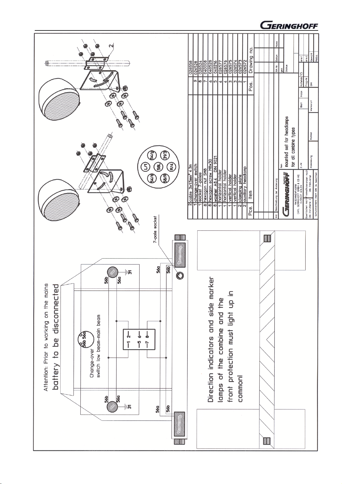
Headlights for combines with foldable corn heads
36 / 500

New Holland CX/CR combine changes on the gathering channel
Changes on the CNH combine gathering channel
Before mounting a header to the CNH-combine of the
series CX and CR it is a must to remove the brackets (L) of
the upper arm location.
Attention !
Only the brackets to remove, since the other mechanism
forms the swivel of the pivoting shield!
Channel view: Brackets removed
Flat steel with screws (S) must be left on the machine.
Holder for upper arm location
To allow for a later use of the upper arm location, an
additional part no. 550900 is supplied along with the
machine.
This additional part is screwed on the existing bracket with
longer screws (M16 x 50).
Holder for upper arm location
Do not weld in the area of the bore
e New Holland.doc

John Deere series 22… conversion to WTS, CTS, STS
A
Setting angle Geringhoff Rota – Disc* header
The ideal working angle for the Rota–Disc header is
about 27°.
When converting the header from one combine make to
another one, in general new adapter parts are required.
When changing from a rigid, not foldable header from the
series JD 22.... to WTS, CTS or STS, that could be done
without the need for using new adapter parts.
That does not apply to „ Hillmaster“ versions
John Deere WTS, CTS and STS combines
If a not foldable corn header is provided for the series JD
22.... to WTS, CTS or used to STS, the channel angle (M)
is to be adjusted to the lowest possible size (M).
This adjustment allows approaching to the required
working angle of the corn header Rota-Disc.
further adjustment of the working angle of the header can
be made via the standard angle adjustment of the header
(see also 09/480.
Multicoupler for hydraulic connection
Combines of the series WTS, CTS and STS are fitted with
a multicoupler for the hydraulic connection to the header.
This coupler must be provided along with the adapter parts
for being able to operate the header.
Conversion of folding Rota-Disc* headers from
JD 22... to John Deere WTS, CTS or STS
These changes require in any case using new adapter
parts, since the PTO-shaft coupler requires an exact
adaptation of the driving point.
New adapter parts are also required when changing from
series JD 22.. to WTS, CTS or STS on „ Hillmaster“
versions.
e John Deere.doc

John Deere series 22… conversion to WTS, CTS, STS
Feed opening of the corn header
Certain opening sizes of the header for all combine makes
and models are determined for the feeding to the gathering
channel of the combine.
The exact opening width to be learnt from the sketches in
the spare part catalogue from picture table 60/.. .
For standardization reasons, slight variations from the rated
size are allowed.
In particular when working on slopes a regular feeding is of
essence for the harvest material to be distributed evenly
within the machine.
Adaptation to combine width
If the corn header is changed between different combine
makes and types, it must possibly be adapted to the
different machine width.
The plates (12 and 13) are to be put to the required size to
ensure a homogenous machine feeding.
The width (M) of the header opening is to be adapted to
that of the combine.
John Deere-2.doc
 Loading...