

Page 1

July 2000
The information in this document is subject to change without notice and
should not be construed as a commitment by the manufacturer.
The manufacturer assumes no responsibility for any errors that might appear in
this document.
The software described in this document is furnished under a license and may
be used or copied only in accordance with the terms of such license. No
responsibility is assumed for the use or reliability of software or equipment that
is not supplied by the manufacturer or its affiliated companies.
Restricted Rights: Use, duplication, or disclosure by the U.S. Government is
subject to restrictions as set forth in subparagraph (c) (1) (ii) of the Rights in
Technical Data and Computer Software clause at DFARS 252.227-7013.
© Compal Electronics 1999. All Rights Reserved.
Pentium is a registered trademark of Intel Corporation.
MS-DOS and Windows are registered trademarks of Microsoft Corporation.
Sound Blaster is a registered trademark of Creative Labs Corporation.
Macrovision is a registered trademark of Macrovision Corporation.
ATI is a registered trademark of ATI Technology Inc.
ESS and Maestro are registered trademarks of ESS Technology Inc.
All other trademarks and registered trademarks are the property of their
respective holders.
i
Page 2

The FCC wants you to know...
This equipment has been tested and found to comply with the limits for a Class
B digital device, pursuant to Part 15 of the FCC rules. These limits are
designed to provide reasonable protection against harmful interference in a
residential installation.
Any changes or modifications made to this equipment may void the user’s
authority to operate this equipment.
This equipment generates, uses, and can radiate radio frequency energy and, if
not installed and used in accordance with the instructions, may cause harmful
interference to radio communications. However, there is no guarantee that
interference will not occur in a particular installation. If this equipment does
cause harmful interference to radio or television reception, which can be
determined by turning the equipment off and on, the user is encouraged to try
to correct the interference by one or more of the following measures:
• Reorient or relocate the receiving antenna.
• Increase the separation between the equipment and receiver.
• Connect the equipment into an outlet on a circuit different from that to
which the receiver is connected.
• Consult the dealer or an experienced radio/TV technician for help.
• All external cables connecting to this basic unit must be shielded. For
cables connecting to PCMCIA cards, see the option manual or installation
instructions.
ii
Page 3

Federal Communications Commission (FCC)
PART 68 Warning
This equipment complies with Part 68 of the FCC Rules. On the bottom of the
computer is a label that contains, among other information, the FCC
Registration Number and Ringer Equivalence Number (REN) for this
equipment. You must, upon request, provide this information to your
telephone company.
FCC Part 68 Registration Number:
REN:
The REN is useful to determine the quantity of devices you may connect to
your telephone and still have all of those devices ring when your number is
called. In most, but not all areas, the sum of the REN’s of all devices should
not exceed five (5.0). To be certain of the number of devices you may connect
to your line, as determined by the REN, you should call your local telephone
company to determine the maximum REN for your calling area.
If your MODEM causes harm to the telephone network, the local Telephone
Company may discontinue your service temporarily. If possible, they will
notify you in advance. However, if advanced notice isn’t practical, you will be
notified as soon as possible. You will be informed of your right to file a
complaint with the FCC.
Your telephone company may make changes in its facilities, equipment,
operations, or procedures the could affect the proper functioning for your
equipment. If they do, you will be notified in advance to give you an
opportunity to maintain uninterrupted telephone service.
iii
Page 4

CANADIAN DOC NOTICE
This digital apparatus does not exceed the Class B limits for radio noise
emissions from digital apparatus as set out in the Radio Interference
Regulation of the Canadian Department of Communications.
"Le présent appareil numérique n’èmet pas de bruits radioélectriques dépassant
les limites applicables aux appareils numériques de la class B prescrites dans le
Règlement sur le brouillage radioélectrique édicté par le ministère des
Communications du Canada"
Macrovision License of Notice
This product incorporates copyright protection technology that is protected by
method claims of certain U.S. patents and other intellectual rights owned by
Macrovision Corporation, and other rights owners. Use of this copyright
protection technology must be authorized by Macrovision Corporation, and is
intended for home and other limited viewing uses only unless otherwise
authorized by Macrovision Corporation. Reverse engineering or disassembly
is prohibited.
Dolby License of Notice
Manufactured under license from Dolby Laboratories.
iv
Page 5

Table of Contents
Chapter 1 ............................................................................................................. 1
Introducing the Notebook ......................................................................................................... 1
Features and Controls ............................................................................................................. 2
Optional Devices .................................................................................................................... 7
Unpacking & Checking the Equipment .................................................................................. 7
Identifying Parts of the Notebook........................................................................................... 8
Installation and Initial Setup ................................................................................................. 16
Chapter 2 ........................................................................................................... 21
The BIOS Setup Program ....................................................................................................... 21
Introduction .......................................................................................................................... 21
Navigating through the BIOS Setup Program ...................................................................... 22
The Main Menu .................................................................................................................... 26
The System Devices Menu ................................................................................................... 29
The Security Menu ............................................................................................................... 34
The Power Menu .................................................................................................................. 36
The Boot Menu..................................................................................................................... 40
The Exit Menu ...................................................................................................................... 41
Chapter 3 ........................................................................................................... 45
Operation ................................................................................................................................. 45
Introduction .......................................................................................................................... 45
Video Display Controls ........................................................................................................ 45
Some Important Keys on the Keyboard ................................................................................ 46
Cursor Control Keys and Editing Keys ................................................................................ 48
The Function Keys ............................................................................................................... 49
Embedded Numeric Keypad ................................................................................................. 50
Hot Keys for System Control ............................................................................................... 51
The System Status Indicator Panel ....................................................................................... 52
Definition Tables for the LED Status Indicators .................................................................. 54
Battery Charging Control ..................................................................................................... 56
Using the Touch Pad ............................................................................................................ 56
v
Page 6

The FIR Module ................................................................................................................... 58
Multimedia Sound System .................................................................................................... 60
The CD-ROM Module ......................................................................................................... 62
Audio Volume Control ......................................................................................................... 63
Chapter 4 ........................................................................................................... 65
Peripherals ............................................................................................................................... 65
Additional Equipment .......................................................................................................... 65
Connecting Peripheral Devices ............................................................................................ 69
Chapter 5 ........................................................................................................... 77
The Power System.................................................................................................................... 77
The AC Adapter ................................................................................................................... 78
The Battery Power System ................................................................................................... 79
Removing the Battery Pack .................................................................................................. 81
Inserting the Battery Pack..................................................................................................... 82
Automatic Battery Pack Charging Function ......................................................................... 83
AC Power Connection .......................................................................................................... 84
Using Battery Power ............................................................................................................. 85
Battery Status Indicator ........................................................................................................ 85
Low Battery Activity ............................................................................................................ 87
Small Battery for Real Time Clock ...................................................................................... 87
Power Management Habits ................................................................................................... 87
Power Management Modes .................................................................................................. 89
Controllable Features ........................................................................................................... 93
Smart CPU Mode ................................................................................................................. 94
Cover Lid Switch .................................................................................................................. 94
Reactivating From Power Saving Modes ............................................................................. 94
Power Management Summary .............................................................................................. 95
The APM Interface ............................................................................................................... 96
The Advanced Configuration and Power Interface (ACPI) .................................................. 97
vi
Page 7

Chapter 6 ........................................................................................................... 97
Expansion Options .................................................................................................................. 97
System Memory Expansion .................................................................................................. 97
Installing Memory Cards ...................................................................................................... 97
Removing and Installing Modules ...................................................................................... 100
Replacing the Battery Module ............................................................................................ 102
Removing and Installing HDD Modules ............................................................................ 101
Removing and Installing the HDD Module ........................................................................ 103
Removing and Installing a Mini PCI Card ......................................................................... 106
The I/O Port Replicator ...................................................................................................... 106
The AC Adapter and Peripherals Connection..................................................................... 108
The Notebook to I/O Port Replicator Connection .............................................................. 108
Removing the Notebook from the I/O Port Replicator ....................................................... 110
I/O Replicator Specifications ............................................................................................. 111
Chapter 7 ......................................................................................................... 113
Software ................................................................................................................................. 113
Driver Installation ............................................................................................................... 113
VGA Device Driver Installation ......................................................................................... 114
Audio Device Driver Installation........................................................................................ 115
Mini PCI Modem Device Driver Installation ..................................................................... 119
Touch Pad Driver Installation ............................................................................................ 123
Chapter 8 ......................................................................................................... 129
Caring for your Notebook ..................................................................................................... 129
General Maintenance .......................................................................................................... 129
Cleaning the Computer ....................................................................................................... 130
Safety Precautions .............................................................................................................. 133
Appendix A ...................................................................................................... 135
Troubleshooting ..................................................................................................................... 135
An Approach to Troubleshooting ....................................................................................... 136
I/O Connections .................................................................................................................. 138
Appendix B ...................................................................................................... 139
Specifications ......................................................................................................................... 139
vii
Page 8

Table of Figures
Figure 1-1: Right Front View with Display Panel Closed ............................................................. 8
Figure 1-2: Left Front View with Display Panel Closed ............................................................. 10
Figure 1-3: Rear View of Notebook ............................................................................................ 12
Figure 1-4: Right Front View with Display Panel Open .............................................................. 13
Figure 1-5: System Status Indicator Panel ................................................................................... 14
Figure 1-6: Connecting the Power Cord and the AC Adapter ..................................................... 16
Figure 2-1: The Setup Main Menu .............................................................................................. 26
Figure 2-2: The System Devices Menu ....................................................................................... 29
Figure 2-3: The Security Menu.................................................................................................... 34
Figure 2-4: The Power Menu....................................................................................................... 36
Figure 2-5: The Boot Menu ......................................................................................................... 40
Figure 2-6: The Exit Menu .......................................................................................................... 41
Figure 3-1: The Keyboard Layout ............................................................................................... 46
Figure 3-2: Cursor Control and Text Editing Keys ..................................................................... 48
Figure 3-3: The Embedded Numeric Keypad .............................................................................. 50
Figure 3-4: The System Status Indicators .................................................................................... 52
Figure 3-5: The Touch Pad .......................................................................................................... 56
Figure 3-6: The FIR (Fast Infrared Module) ............................................................................... 58
Figure 4-1: Connecting an External Monitor to the Notebook’s VGA Port ................................ 69
Figure 4-2: Connecting a Printer to the Notebook’s Parallel Port ............................................... 70
Figure 4-3: Connecting a Mouse to the Notebook’s Serial Port .................................................. 71
Figure 4-4: Connecting an External Keyboard to the Notebook’s PS/2 Port ............................... 72
Figure 4-5: Inserting and Ejecting a PCMCIA Card ................................................................... 73
Figure 4-6: Connecting a USB Device ........................................................................................ 75
Figure 5-1: The Notebook’s AC Power Adapter ......................................................................... 78
Figure 5-2: The Notebook’s Battery System ............................................................................... 79
viii
Page 9

Figure 5-3: Removing the Battery Pack....................................................................................... 81
Figure 5-4: Inserting the Battery Pack ......................................................................................... 82
Figure 5-5: Connecting the AC Adapter to the Notebook’s AC port ............................................ 84
Figure 6-1: Removing the Memory Door and Installing the Memory Card................................. 99
Figure 6-2: Removing the CD-ROM Module ............................................................................. 100
Figure 6-3: Installing the CD-ROM Module .............................................................................. 101
Figure 6-4: Removing the HDD Module (A) ............................................................................ 102
Figure 6-5: Removing the HDD Module (B) ............................................................................. 103
Figure 6-6: Replacing the HDD Module ................................................................................... 103
Figure 6-7: Removing the FDD Module (A) ............................................................................. 105
Figure 6-8: Removing the FDD Module (B) ............................................................................. 106
Figure 6-9: Installing a Mini PCI Cards .................................................................................... 108
Figure 6-10: The I/O Replicator’s Ports .................................................................................... 109
Figure 6-11: Connecting the Notebook to the I/O Port Replicator ............................................ 111
Figure 6-12: Removing the Notebook from the I/O Replicator ................................................. 112
ix
Page 10

Abbreviations
Abbreviation Meaning
ACPI
APM
BIOS
CMOS
DIMM
DMA
DRAM
DVD
EDO RAM
IDE
FIR
GB
ISA
KB
LCD
MB
MIDI
MPEG
MS-DOS
PCI
PCMCIA
POST
PnP
RAM
RAMDAC
ROM
VGA
SVGA
UART
XGA
YUV
Advanced Configuration and Power Interface
Advanced Power Management (This Notebook supports APM 1.2)
Basic Input/Output System
Complementary Metal Oxide Semi-conductor
Dual In-line Memory Module
Direct Memory Access
Dynamic Random Access Memory
Digital Versatile Disc
Extended Data Out Random Access Memory
Integrated Drive Electronics (internal hard disk drive interface)
Fast Infrared
Gigabyte (1GB = 1,073,741,824 bytes or 1,024MB)
Industry Standard Architecture
Kilobyte (1KB = 1,024 bytes)
Liquid Crystal Display
Megabyte (1MB = 1,048,576 bytes or 1,024KB)
Musical Instrument Digital Interface
Motion Picture Experts Group
Microsoft Disk Operating System
Peripheral Component Interconnect
Personal Computer Memory Card International Association
Power On Self-Test
Plug and Play
Random Access Memory
Random Access Memory Digital to Analog Converter
Read Only Memory
Video Graphics Array
Super Video Graphics Array
Universal Asynchronous Receiver Transmitter
Extended Graphics Array
The video native signal format
x
Page 11

ABOUT THIS GUIDE
This guide describes how to operate, configure, and troubleshoot the Notebook computer. With this easy to use guide, you will be able to quickly
familiarize yourself with all aspects of the Notebook computer.
Organization
This guide contains the following:
Chapter 1: Introducing the Notebook - This chapter identifies the external
components of the Notebook and provides a quick reference to the Notebook
functions. It also shows you how to get the Notebook up and running for the
first time and covers creating a comfortable working environment.
Chapter 2: The BIOS Setup Program - This section introduces the Setup
program, discusses how to move around in the Setup program, as well as how
to specify and save your new settings. A detailed list of the optional settings
among the different menus is also provided.
Chapter 3: Operation - This chapter provides information pertaining to the
Video Display Controls used to adjust the LCD screen’s appearance. Also
included in this chapter is a brief overview of the keyboard, the System Status
Indicator Panel, the touch pad, the FIR module, and a description of the audio
features of the Notebook.
Chapter 4: Peripheral Devices - This chapter overviews the peripherals that
can be connected to the Notebook, the necessary requirements for using these
peripherals with your Notebook and instructions on how to connect these
devices to your Notebook.
Chapter 5: Power System - This chapter contains information on the
Notebook’s power system, including the AC Adapter, the battery system,
recharging the battery, and tips for conserving battery power. Also included is
a detailed description of power management.
Chapter 6: Expansion Options - This chapter describes the optional
equipment that can be added to the basic Notebook system. Also covered in
this chapter is step-by-step information on installing and removing the optional
modules that can be inserted in the Notebook.
Chapter 7: Software - This chapter provides step-by-step instructions for
installing Windows 98 device drivers.
xi
Page 12

Chapter 8: Caring for Your Notebook - This chapter covers some of the basic
maintenance procedures you may want to familiarize yourself with. It
introduces proper methods of cleaning the case, the screen, the FDD drive, as
well as some helpful tips on handling diskettes.
Appendix A: Troubleshooting - In a question and answer format, this section
provides you with solutions to possible problems that may arise.
Appendix B: Technical Specifications - This appendix lists your Notebook
computer’s operating specifications.
Special Notices
Three kinds of special notices are used in this guide to emphasize specific
information.
Provides additional information.
Indicates the presence of a hazard that can cause damage to
the Notebook or other equipment.
xii
Alerts you to a condition that may hamper the performance
of the Notebook.
Page 13

C
HAPTER
INTRODUCING THE NOTEBOOK
Your new Notebook features the most innovative advances in portable
computing technology. It combines state-of-the-art ergonomics with
sophisticated architecture to provide you with a personal computer that is
compact, powerful, and easy to use.
The modular design of the Notebook provides maximum expandability without
compromising portability. The high-performance Pentium III CPU and PCI
hard drive provide you with the extra processing power needed to handle
complex graphics and large sound files. Two PCMCIA slots give you the
ability to use standard PCMCIA cards, such as a LAN adapter or memory
cards. The Notebook’s CD-ROM located on the front panel of the Notebook
for easy access provides access to a greater variety of graphics and multimedia
software.
1
This User’s Guide describes all the features of the Notebook in an easy-to-read
yet thorough manner. The primary goals of this chapter are to identify the
Notebook’s external components and to provide a quick reference of the
Notebook functions for experienced computer users.
Page 14

Notebook User’s Guide
Features and Controls
This section provides an overview of the Notebook’s features. For more
detailed information see the Specifications section in Appendix B. Your
Notebook includes the following features:
CPU
The microprocessor (CPU) is the heart and brain of the computer. It performs
all the computing functions and orchestrates the actions of the system. Your
Notebook features the state-of-the-art Pentium III with the Intel 440BX system
controller chip set .
CPU upgrades are possible. Changing a CPU requires much skill and
knowledge. If you are not absolutely sure that you have the capability to
change a CPU by yourself, let your Notebook dealer do it for you. Removing
the CPU in an improper way may damage the Notebook’s main board,
resulting in costly repairs.
FDD Module
The FDD can use either 720KB double density or 1.44MB high-density 3.5inch floppy diskettes. Floppy diskettes are useful for making backups of your
program diskettes and data files. The FDD can be replaced with an optional
LS120 module.
CD-ROM Module
The Notebook is equipped with a 24X (or faster) CD-ROM drive. The CDROM can be replaced with an optional DVD or ZIP module.
Hard Drive
The Notebook comes with a 2.5"/9.5mm, or 12.7mm high hard disk (up to
16GB) installed. Features include an HDD interface with PCI Bus Master IDE
and support for Ultra 33 synchronous DMA (ATA-33) and PIO Mode 4 timing.
Consult your dealer to find out the capacity of the hard drive installed in your
Notebook.
2
Page 15

Chapter 1: Introducing the Notebook
LCD VGA Display
Your Notebook’s VGA display is one of three models:
• Color TFT-14.1" LCD panel supporting 1024 x 768 XGA resolution
• Color TFT-15.0" LCD panel supporting 1024 x 768 XGA resolution
• Color TFT-15.0" LCD panel supporting 1280 x 1024 SXGA resolution
VGA Graphics Accelerator and Video Subsystem
This Notebook is equipped with ATI 3D RAGE Mobility-P for N30W and
ATI 3D RAGE Mobility-M3 for N38W2 VGA AGP controller chip offering
the following features:
• AGP 2X Bus Architecture (133MHz)
• Integrated 230MHz DAC
• Integrated ImpacTV2-quality TV output
• Integrated dual-channel 112MHz LVDS transmitter
• Supports Tri-View architecture allowing for simultaneous video output to
LCD/CRT/TV displays
• Superior 2D performance with 125MHz SGRAM
• Superior 3D acceleration achieved through a hardware setup engine and a
4KB on-chip texture cache
• Support for 4 or 8 MB of SGRAM Display Memory for N30W and supports
16 MB Display Memory for N38W2
• ACPI compliant Dynamic Power Management features
• Full motion soft DVD using motion compensation circuitry
• Capture and MPEG support with Zoom Video (ZV) port video input
• Plug and play monitor support
• Fully compliant with PC98 and PC99
87/88-key Enhanced Keyboard
The Notebook’s keyboard has a standard QWERTY layout with the addition of
special function keys. It is available in either 87 or 88-key layouts that emulate
a full-size desktop 101/102-key keyboard. The keyboard features an
embedded numeric keypad for number-intensive data entry, with independent
[Page Down], [Page Up], [Home], and [End] keys.
Windows 95/98 Enhanced Keyboard
The keyboard supports Windows 95/98 by incorporating two Windows
specific keys. With these keys you will be able to access and take advantage of
many of the time-saving features offered by Windows 95/98.
3
Page 16

Notebook User’s Guide
The Touch Pad
The Notebook features a touch pad pointing device with two buttons. This
pressure-sensitive pointing device allows you to move the cursor around the
screen and make selections just as one would with a conventional mouse. A
unique function called double tapping allows you to make selections within a
software program or execute software applications without having to remove
your hands from the touch-type position. Please see the Touch Pad section in
Chapter 3 for more information on the operation of the Notebook’s pointing
device.
Connectors
The Notebook has a number of connector (Input/Output) ports for attaching
peripherals to the computer, including the following:
• A 6-pin connector for a full-size keyboard or a PS/2 mouse
• Three audio jacks: External Mic (Mic-in), Headphone-out and Line-in
• A 15-pin CRT (monitor) port
• A standard 9-pin serial port (16550 compatible) supports a variety of serial
devices such as a mouse or MODEM.
• A 25-pin parallel port that is most commonly used to connect a printer or
Pocket LAN to the computer. The parallel port supports both EPP and ECP
capabilities.
• A 240-pin docking connector with 32-bit PCI bus and hot docking support
• Two ACPI-compliant PCMCIA expansion sockets provide an interface for
two Type II cards, or one Type III card. PC cards accommodate a number
of expansion options, including memory cards, MODEMs, hard disks, and
network adapters.
• One 2-pin connector for an AC Adapter power jack
• Built-in IrDA FIR (Fast Infrared) transmitter/receivers for wireless
communications
• One built-in microphone
• Two built-in speakers
• One 4-pin Universal Serial Bus (USB) connector
• One TV-Out (S-type) port
• RJ-11 MODEM port
4
Page 17

Chapter 1: Introducing the Notebook
PCMCIA Sockets
An ACPI-compliant PCMCIA R2.0 host adapter supports one type III
PCMCIA card or two type II PCMCIA cards. The PCMCIA sockets support
hot insertion and removal and can accommodate SRAM, OTPROM,
FLASHROM and Mask ROM memory cards of up to 64MB, MODEM/LAN
cards and 10.5mm removable HDD.
Battery and AC Power System
To power the Notebook, you can use an AC Adapter or the rechargeable
battery pack module. The system will automatically recharge the battery pack
in the Notebook by using the AC Adapter. For information on recharging the
battery while simultaneously using the Notebook, see the section in this chapter
on installation and initial setup. By using the power management features
described in Chapter 5, the Notebook can operate on battery power for
approximately 3 hours. The battery pack takes approximately 2 hours to
recharge when the computer is turned off. It takes 2.5 hours to recharge when
the computer is in use. For extended battery-powered operation, additional
battery modules may be purchased.
Upgradable Memory
The Notebook is equipped with two SODIMM connectors, allowing for a
maximum of 256MB of system memory to be installed. This memory
configuration is achieved by installing two 32MB, 64MB or 128MB 3.3V
SDRAM 144-pin SO-DIMM memory module. Refer to the System Memory
Expansion and Installing Memory Cards sections in Chapter 6 for detailed
information on upgrading system memory. After reviewing the appropriate
sections, if you are not completely confident that you have the skill to install
memory modules by yourself, please consult your Notebook dealer or
technician.
Built-in Level 2 Cache RAM
The Notebook provides 256KB (for Pentium III) or 128K (for Celeron) L2
Cache RAM that will enhance system performance, especially in the Windows
environment.
Keyboard Controls
The Notebook provides a host of hot key features that are a permanent part of
the computer’s operation. Some affect the LCD video display, while others
control the sound volume. A complete list of the Notebook’s hot key functions
is provided in Chapter 3.
5
Page 18

Notebook User’s Guide
Power Management
The Notebook features sophisticated power management built into the BIOS
Setup program. These features are designed to conserve power and extend the
life of the battery between charges.
FIR Port
For convenience, the Notebook features an FIR Port (on the rear panel) that
allows wireless, serial communication between the Notebook and other FIR
equipped devices such as a printer or another computer. The FIR Port allows
both the sending and receiving of data.
Audio Features
The Notebook’s audio features include:
• ESS Maestro-2E digital audio controller (Sound Pro™ and Windows Sound
System™ compatible)
• 64-channel wavetable synthesizer
• Proprietary WaveCache technology
• HRTF 3-D positional audio under DirectX™ 5.0
• A sophisticated on-board 16-bit stereo FM sound generator featuring
enhanced stereo and full-duplex playback and record with internal playback
and record buffer
• Sample rate conversion from 8Khz to 48Khz
• Secondary CODEC Interface
• DVD AC-3 Speaker Virtualization
• Two integrated speakers and an internal microphone
• Stereo inputs for Line-in and Line-out and a mono input for the microphone
• Software/Hardware Master Volume Control
• Programmable Power Management
• MIDI serial port compatible with MPU401 UART mode
• I2S interface to internal stereo D/A for external ZV port or MPEG audio
• PC98 compliant with full PnP support
• Complies with Microsoft ACPI 1.0 and PPMI 1.0 (DO-D3) and APM 1.2
• Legacy DOS Game support
6
Page 19

Optional Devices
There are several optional products you can purchase to further enhance the
utility and versatility of your Notebook computer.
• HDD Module (factory option)
• CD-ROM Module
• DVD Module
• LS120 Module (factory option) for N30W, N38W2 don’t support
• Zip Module
• Mini PCI 56K Data/Fax/Modem (factory option)
• TV-out Adapter
• S-Type TV Video and Audio cable
• Docking Station
(Port Replicator / Enhanced Port Replicator / Docking Station TBD)
• Extra memory modules (32, 64, 128MB 144-pin 3.3V SODIMM)
• Li-Ion Main Battery Pack
• Li-Ion Secondary Battery Pack
• External Battery Charger
Chapter 1: Introducing the Notebook
Unpacking & Checking the Equipment
Before unpacking the Notebook, prepare a clean, stable surface on which to
place the contents of your Notebook’s shipping container. Altogether, you
should find the following items in the Notebook package:
• The Notebook Computer (with one battery pack already installed)
• FDD Module
• CD-ROM Module
• An AC Adapter
• A Power Cord
• A Carrying Bag (optional)
• Support Diskettes/CD
• This User’s Manual
Remove all the items from the container. If anything is missing or broken,
inform your dealer immediately. You should save the packaging; if you ever
need to ship your Notebook or send it in for service, the shipping container
will definitely be useful.
7
Page 20
Notebook User’s Guide
4
10
Identifying Parts of the Notebook
The illustrations that follow identify the various features and external
components of the Notebook computer. Familiarizing yourself with these
terms will help you as you read the rest of the manual.
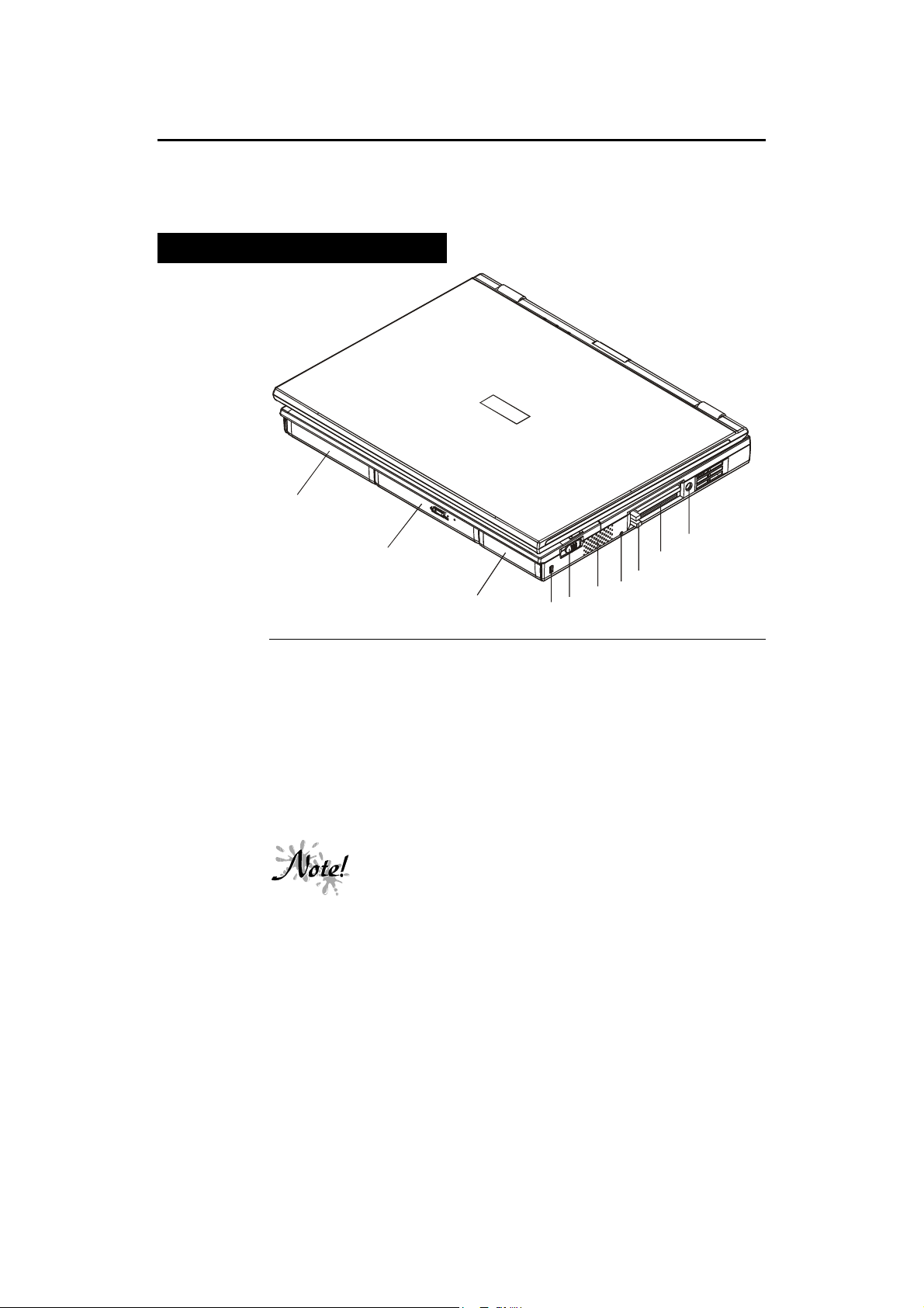
Right Front View (Panel Closed)
1
2
3
Figure 1-1: Right Front View with Display Panel Closed
1. Removable Battery Module
Your Notebook comes equipped with a factory-installed battery pack module.
After the battery runs down, the module can be removed and replaced with a
charged battery. Additional battery packs can also be purchased as optional
equipment.
2. CD-ROM Module
Your Notebook comes equipped with a factory-installed CD-ROM module.
8
The CD-ROM module can be removed and replaced
with an optional DVD, ZIP or secondary battery
module. Contact your Notebook PC dealer for more
5
6
7
9
8
Page 21

Chapter 1: Introducing the Notebook
information.
3. Removable HDD Module
Your Notebook comes equipped with a factory-installed HDD module. If you
find that your Notebook is running low on disk space, the HDD can be
removed an replaced with a higher capacity HDD (up to 16GB).
4. Kensington Lock
This port is for locking the Notebook PC to a desk for security.
5. LCD Panel Release Button
The Notebook has two LCD panel release buttons located on the left and right
side panels. To open the Notebook, slide these release buttons forward. This
will release the LCD panel latches. Now raise the panel to its open position as
shown in Figure 1-4. Note that the Notebook’s LCD panel can be adjusted to
an angle ranging from 0° to 180°. Adjust the LCD panel for a comfortable
viewing angle.
6. Internal Stereo Speaker
The Notebook provides three audio-output choices: wearing headphones
connected to the audio Headphone-out jack for private listening; connecting
external stereo speakers to the audio Headphone-out jack for high quality
sound; or for convenience, using the internal stereo speakers.
7. Power Kill Button
Pressing this button will shut down the system. All unsaved data will be lost.
8. PCMCIA Socket Eject Buttons
Push the upper button to release a PCMCIA Type I or Type II card from the
upper slot. Push the lower button to release a PCMCIA Type I, Type II, or a
Type III card from the lower socket.
9. PCMCIA sockets
Insert PCMCIA Type I, Type II, or Type III cards into these sockets.
10. AC Power Jack
Connect the AC Adapter power cord to this jack.
9
Page 22
Notebook User’s Guide
3
4
5
6
7
8
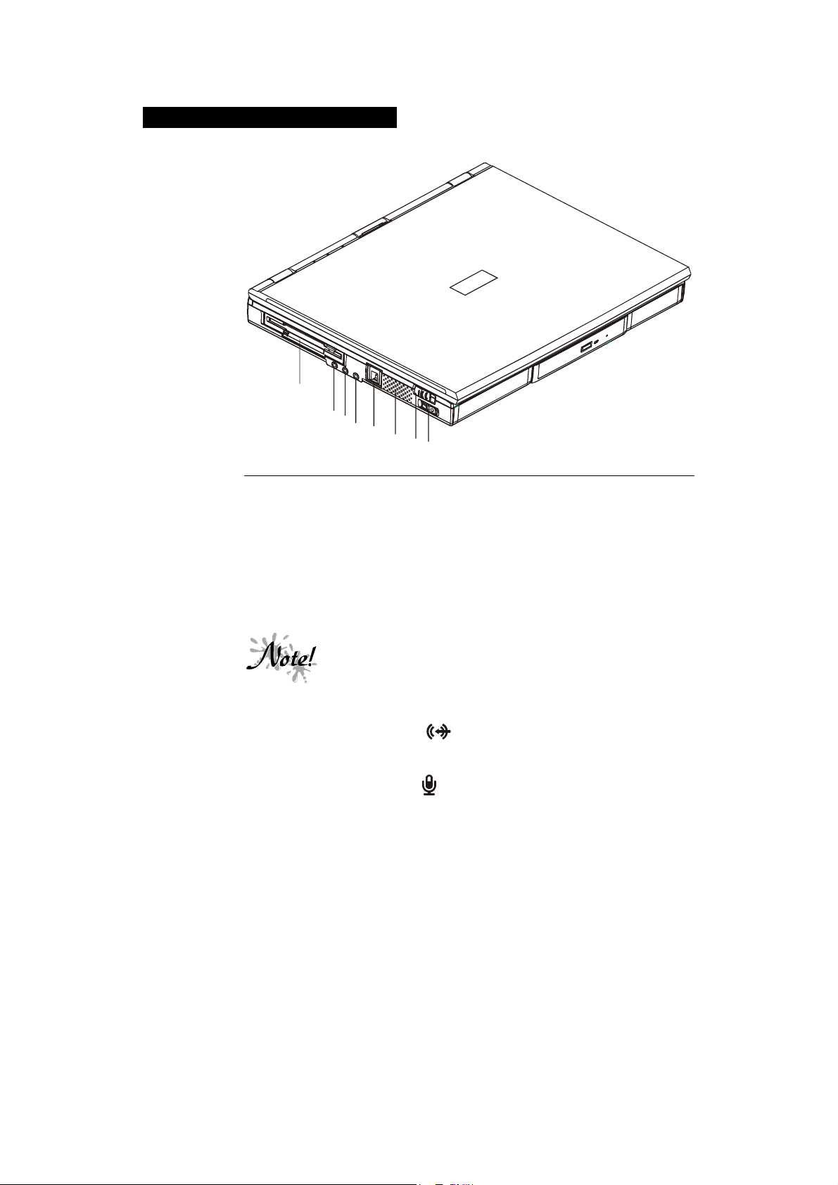
Left Front View (Panel Closed)
1
2
10
Figure 1-2: Left Front View with Display Panel Closed
1. FDD Module or LS120 Module
Your Notebook comes equipped with a factory-installed FDD module or
LS120 Module. Insert 3.5-inch floppy diskettes into the floppy disk drive.
Press the eject button eject a diskette from the floppy disk drive. This button
only pops out when a diskette is inserted into the drive.
2. Audio Line-in Connector
This stereo jack is used to connect an external audio source to the Notebook.
3. External Mic Connector
This stereo jack is used to connect an external microphone.
The FDD module can be removed and replaced with an
optional LS120 module. Contact your Notebook PC
dealer for more information.
Page 23

Chapter 1: Introducing the Notebook
4. Audio Headphone-out Connector
This stereo jack is used to connect external speakers or headphones. Please
refer to Chapter 3 for information on using Audio control hot keys.
5. RJ-11 MODEM Port
Connect a phone line to this port to make use of the Notebook’s optional
Fax/MODEM MiniPCI card. Refer to Chapter 4, Peripherals for more
information.
6. Internal Stereo Speaker
The Notebook provides three audio-output choices: wearing headphones
connected to the audio Headphone-out jack for private listening; connecting
external stereo speakers to the audio Headphone-out jack for high quality
sound; or for convenience, using the internal stereo speakers.
7. LCD Panel Release Button
The Notebook has two LCD panel release buttons located on the left and right
side panels. To open the Notebook, slide these release buttons forward. This
will release the LCD panel latches.
The Audio jacks are three-terminal stereo jacks but are
used as two terminal mono jacks. They are not
compatible with two-terminal mono plugs.
An optional MiniPCI MODEM module must be installed
in order for the MODEM to function. The RJ-11
MODEM Port will be disabled if the optional MiniPCI
MODEM module is not installed.
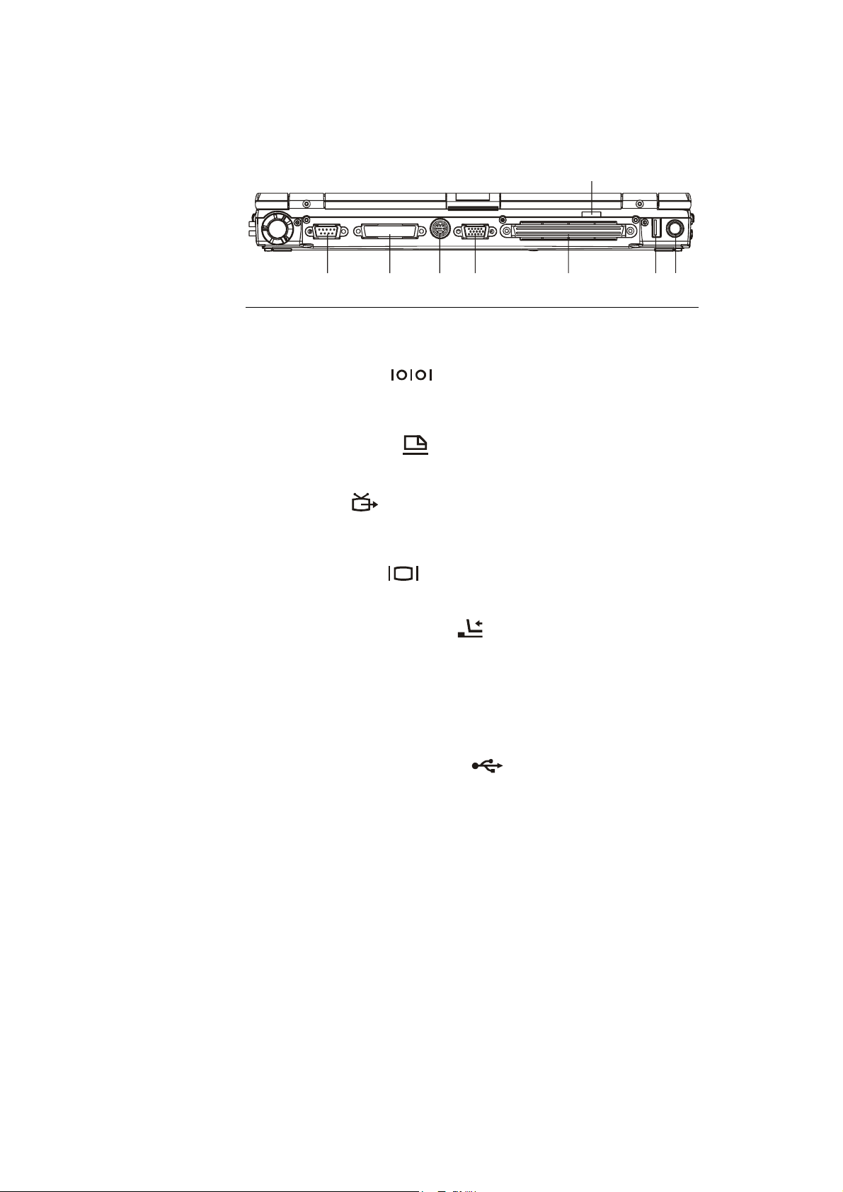
Rear View
8. Hardware Master Volume Control
This control regulates the audio volume output. Press the right side of the
control to increase the volume by increments. Press the left side of the control
to decrease the volume by increments.
11
Page 24
Notebook User’s Guide
1
2
3
4
5
6
7
8
Several I/O ports are located on the rear side of the Notebook. Starting from
left to right, the rear-side ports are introduced below. Please refer to Figure 1-
3 for assistance in locating these ports.
Figure 1-3: Rear View of Notebook
1. Serial (COM) Port
This port is used to connect RS-232 serial devices to the Notebook. Three
types of serial devices are mice, serial printers, and MODEMs.
2. Parallel (LPT1) Port
This port is normally used to connect a printer to the Notebook.
12
3. TV-out Port
Connect a Television set to this port to view the Notebook’s display output on
your TV.
4. VGA Display Port
This port is used to connect an external monitor (CRT) to the Notebook.
5. I/O Port Replicator Connector
This port is for connecting the Notebook to its proprietary I/O Port Replicator.
6. FIR Port
The FIR Module allows wireless communication (transmission and receiving)
between the Notebook and another FIR-equipped computer or between the
Notebook and another FIR-equipped device, such as a printer.
7. Universal Serial Bus (USB) Port
Connect any USB compliant device to this port.
Page 25
8. External Keyboard or PS/2 Mouse Port
1
2
3
4
5
7
This port is for connecting either an external keyboard or a PS/2 mouse.
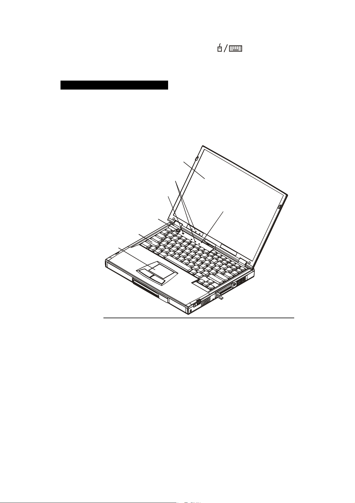
Right Front View (Panel Open)
The Notebook has two LCD panel release buttons located on the left and right
side panels. To open the Notebook, slide these release buttons forward. This
will release the LCD panel latches. Please refer to Figure 1-1 and Figure 1-2
to locate the LCD panel release button. Raise the cover to its open position.
Figure 1-4 shows the Notebook in the open position with the external parts
labeled. As mentioned earlier, the cover can be adjusted to an angle of 0° to
180°. Adjust the LCD cover for a comfortable viewing angle.
Chapter 1: Introducing the Notebook
6
Figure 1-4: Right Front View with Display Panel Open
1. LCD Screen
The screen is a color TFT or DSTN LCD.
13
Page 26
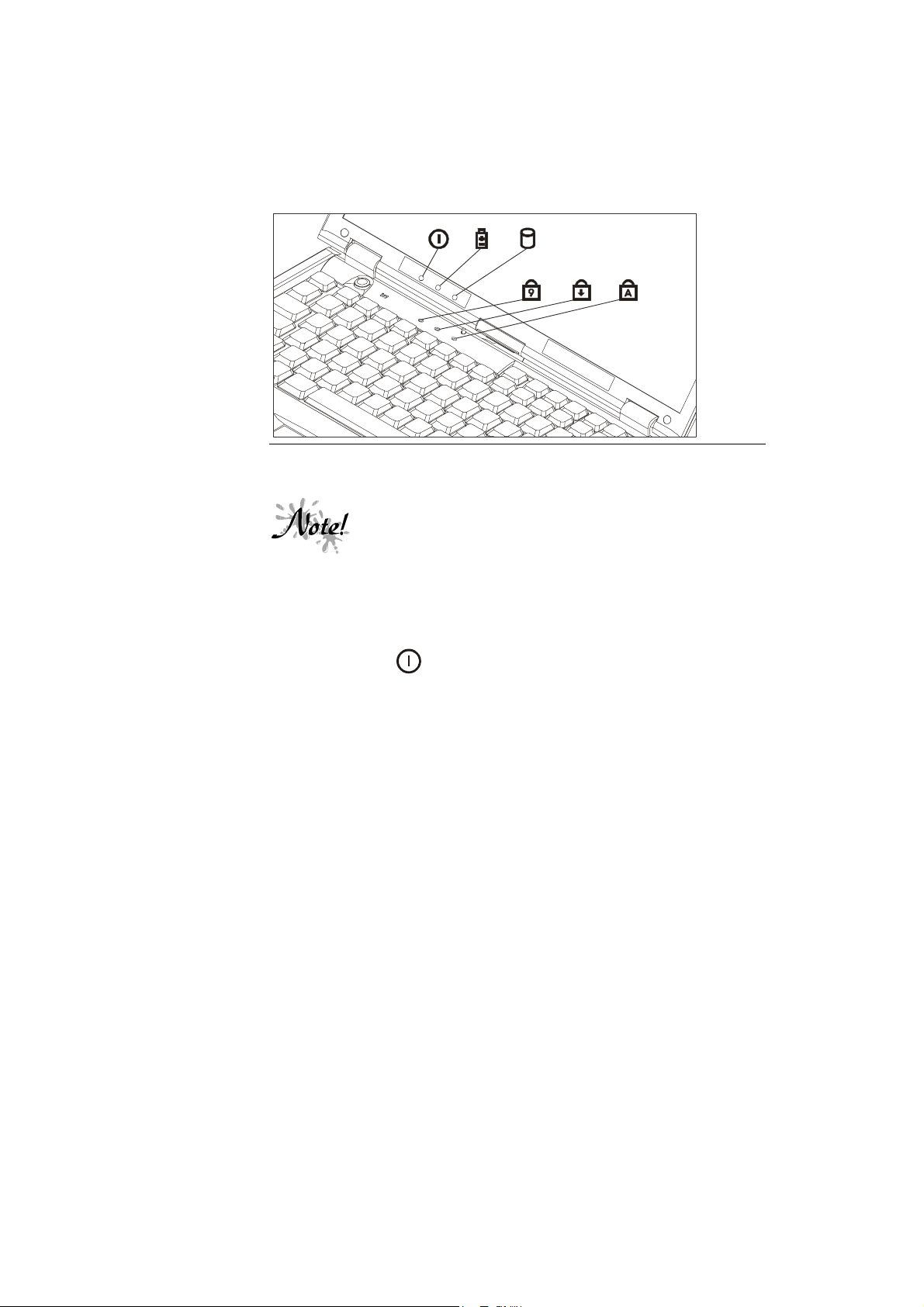
Notebook User’s Guide
2. System Status Indicators
The System Status indicators inform you of the Notebook’s current operating
status at a glance. The different LED indicators are from left to right: AC
Power, Battery Power, HDD Activity, Numlock, Caps Lock, and Scroll Lock.
Refer to chapter 3 for a detailed description of these indicators.
Figure 1-5: System Status Indicator Panel
14
3. Built-in Microphone
The microphone can be used to record music, voice, and sound files.
4. Power Button
Press this button to turn the computer on or off.
5. Keyboard
Your keyboard is either an 87-key US version or an 88-key international
version depending on the Notebook you purchased.
The AC Power, Battery Power, and HDD Activity LED
indicators can be viewed near the panel hinge when
the panel cover is closed.
Page 27

Chapter 1: Introducing the Notebook
6. Touch Pad
The touch pad is a pressure sensitive pointing device that provides all the
features of a mouse. Although its operation differs from a mouse, its function
is quite the same: to move the cursor around the screen. Please refer to Using
the Touch Pad, in Chapter 3 for more information.
7. Suspend/Resume Lid Switch
There are three ways to enter the system into Suspend mode. One is to
automatically enter Suspend mode. The system will enter Suspend mode based
upon the settings made in the Basic Input Output System (BIOS) Setup
program. Although it sounds intimidating, Setup is a simple program to use. It
is covered in detail in Chapter 2.
In the second method, the Suspend/Resume is activated by using the cover
switch. Assuming an external monitor is not connected to the Notebook and
the Notebook is powered on, closing the lid will cause the system to
automatically enter the Suspend mode.
In the third method, the user can activate suspend or resume by pressing a hot
key. Pressing [Fn] + [R] suspends to RAM, and pressing [Fn] + [F12]
suspends to disk. The user can press the power button to resume full power
operation.
For more information on Suspend modes, please see Chapter 5, Power
Management Modes.
15
Page 28
Notebook User’s Guide
Installation and Initial Setup
If you are unfamiliar with computers, this section guides you through turning
on your Notebook for the first time. This section also explains what you need
to do after turning on your Notebook. Experienced computer users may need
only read this section while using the rest of the manual merely as a reference.
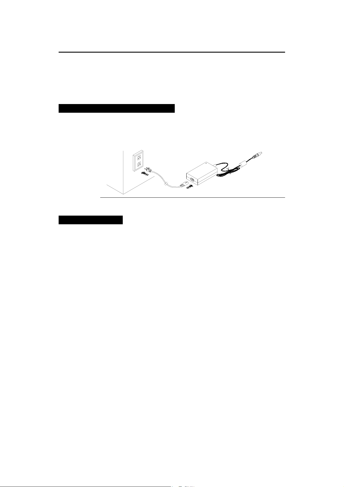
Connecting the AC Power Adapter
There are two possible ways of powering the Notebook. One is by an internal
battery module and the second is by connecting the Notebook’s AC Adapter.
This chapter will focus on the AC connection. Figure 1-6 illustrates this
connection. For information on using battery power, please refer to Chapter 5.
Figure 1-6: Connecting the Power Cord and the AC Adapter
An AC Connection
To power the Notebook by using the external AC Adapter, please refer to
Figure 1-6 and the following instructions:
1. Insert the end of the AC Adapter output cable into the Notebook’s AC port.
Figure 1-6 illustrates this connection. Do not force a connection.
2. The port on the AC Adapter module is shaped like a figure eight with two
pins protruding from it. Connect the power cable to this port.
3. The best power source that you can connect any computer device to is a
UPS (uninterruptable power supply). Your Notebook dealer will be able to
provide you specifics as far as the price and performance of different
brands of UPS devices. If you do not own a UPS and have no desire to
purchase one, your next best power source is an extension cord that has its
own built-in electrical surge protector. If you don’t have an extension cord
with a built-in electrical surge protector, you can plug the AC Adapter
directly into a grounded electrical outlet.
16
Page 29

4. Plug the Notebook into its power source and press the On/Off button. If
the Notebook does not power up, check the connections between the wall
outlet, the AC Adapter, and the Notebook. If the Notebook still does not
power up, please refer to Appendix A, Troubleshooting.
5. To turn the Notebook off, save your work and close all open applications,
click on Start, then Shut Down. In the Shut Down Windows dialog box
select Shut down the computer and click Yes.
If you travel to an area with a different electric power standard, check to make
sure whether that voltage system is compatible with your Notebook’s power
requirements before plugging it into an AC power source. You can use an
adapter plug that interfaces between your system cables and the electrical wall
outlet of the foreign country you are visiting. If you are unsure about this,
please consult your Notebook dealer or support technician.
Your Notebook is equipped with one rechargeable battery pack, which has
already been installed. Please refer to the Power Management section of
Chapter 5 for further coverage of the rechargeable battery and how to optimize
you Notebook PC for battery operation.
The Power On Self Test (POST)
Chapter 1: Introducing the Notebook
When you turn on the computer, it will first run through a series of softwarecontrolled diagnostic tests called the Power On Self Test (POST). The
software that controls the POST is installed as a permanent part of the
computer’s architecture. The POST includes a record of the computer’s
hardware that is used to make a diagnostic check of the system. This record is
created by using the BIOS Setup program. If the POST discovers a difference
between the record and the existing hardware, it will display a message on the
screen prompting you to correct the conflict by running the BIOS Setup
program. Refer to Chapter 2, for instructions on how to run the BIOS Setup
program.
In most cases, the record should be correct when you receive the computer. If
so, the POST will finish and the computer will look for an Operating System to
load into memory. The self test will run every time you turn on the computer.
When the test is finished, you should get a message indicating that there is a
non-system disk or disk error. This indicates that the hard disk is ready to be
prepared for use with the operating system you intend to use. After you
prepare the hard disk for use, you should not see this message again unless you
try to start the computer with a non-system floppy disk inserted in the floppy
drive.
17
Page 30

Notebook User’s Guide
Installing an Operating System
When starting the computer for the first time, please be aware that you must
have an Operating System (OS) program installed on the hard drive. You
probably have an OS program already installed on your Notebook. If your
dealer did not install an OS for you, please consult your OS Software manuals
for instructions on how to install an OS onto your hard disk drive.
Preparing the Notebook for Transport
To prepare the computer for transport, you should first disconnect all
peripherals. Make sure the computer is turned off before you do this. Make
sure the floppy drive does not contain a diskette. When a diskette is inserted in
the floppy drive, the eject button pops out. If you attempt to transport the
Notebook with a diskette in the drive, you risk damaging the eject button.
The computer has an optional soft carrying case. It will keep out dirt and dust
and protect the casing of your Notebook from becoming scratched or cracked.
If you intend to use battery power, be sure to fully charge the battery pack and
any spares. Remember the Adapter charges the battery pack as long as it is
plugged into the computer and an AC power source.
18
Page 31

A Word about Ergonomics
Ergonomics is the study of how people with their different physical
characteristics and ways of functioning relate to their working environment
(the furnishings and machines they use). The goal of Ergonomics is to
incorporate comfort, efficiency, and safety into the design of keyboards,
computer desks, chairs, and other items in an effort to prevent physical
discomfort and health problems in the working environment. Because more
and more people are spending large amounts of time in front of computer
monitors, scientists from many fields including anatomy, psychology, and
occupational safety are involved in the study of ergonomically sound work
environments.
If your budget permits, buy ergonomically designed furniture such as chairs,
shelves, and desks that fit your physical characteristics and work methods.
Most furniture manufacturers have not considered the particular shape of your
body when designing workstations. If you are going to be sitting for extended
periods, an ergonomically designed chair may well be worth the extra expense.
You can, however, create an ergonomically improved workstation without
spending much money. Following are a few tips to help you work effectively
without a lot of physical discomfort:
• Place the monitor so that it is a little above eye level to prevent neck strain.
• Try to place the monitor so that there is little glare from the sun on the
monitor.
• Use a thick book as a footrest.
• Walk around the room every hour.
• Every half-hour, look away from the computer screen for a few minutes.
• Place everything that you need to work within easy reach.
Chapter 1: Introducing the Notebook
19
Page 32

Notebook User’s Guide
Hot Keys for System Control
The following table lists the hot key functions for the Notebook computer.
Key Combinations Definitions
[Fn] + Increases display brightness
[Fn] + Decreases display brightness
[Fn] + [PageUp] Increases audio volume output
[Fn] + [PageDn] Decreases audio volume output
[Fn] + [F8] Switches among LCD, external monitor, and
[Fn] + [End] Toggles the mute function on and off. (no beep)
[Fn] + [number] Pressing [Fn] plus any number on the keypad enables
[Fn] + [Esc] Pressing this hot key combination will cause the system
simultaneous displays
the embedded numeric keypad.
to enter Save to Disk mode (Hibernate mode). The
function of this hot key is configured by the Windows
98 operating system.
20
When ACPI mode is enabled, all power management
hot keys, i.e., Fn + S/R/F12, are inactive.
When using an external keyboard, the Fn key can be
simulated by pressing the left-Ctrl + left-Alt keys.
This concludes Chapter 1. The next chapter covers the BIOS Setup program.
Page 33

C
HAPTER 2
THE BIOS SETUP PROGRAM
Introduction
The BIOS (Basic Input and Output System) Setup program is a menu driven
utility that enables you to make changes to the system configuration and tailor
the operation of your Notebook to your individual work needs. A ROM-based
configuration utility displays the system’s configuration status and provides
you with a tool to set system parameters. These parameters are stored in nonvolatile battery backed-up CMOS RAM, which saves this information even
when the power is turned off. When the computer is turned back on, the
system is configured with the values found in CMOS. Using easy-to-use
menus, you can configure such items as:
• Hard drives, diskette drives and peripherals
• Video display options
• Password protection from unauthorized use
• Power Management Features
The settings made in the Setup program intimately affect how the Notebook
performs. It is important, therefore, first to try to understand all the available
options, and second, to make settings appropriate for the way you use the
Notebook. This chapter will guide you through the Setup program by
providing clear explanations for all Setup options.
A standard configuration has already been set in the Setup program by the
factory technicians, so you will very likely have little to worry about for now.
However, eventually you may want to customize your system to suit your own
performance needs. It is recommended that you read this chapter and become
familiar with the adjustments that can be made in the BIOS.
The next section explains how to move around in the Setup program, as well as
how to specify and save your new settings. A brief discussion of the optional
settings among the different submenus follows.
Page 34

Notebook User’s Guide
Navigating through the BIOS Setup Program
The Setup program has been designed to make it as easy to use as possible. It
is a menu driven program, which means you can scroll through the various
directories and make your selections among the various predetermined choices.
If you accidentally make a setting and do not know which one to switch back
to, use the BIOS hot keys to return to the previous value. The hot keys are
discussed in more detail later in this chapter.
When turning on the Notebook for the first time you may get a message
prompting you to run the BIOS Setup program. A warning message may
appear on the screen if the hardware configuration is changed or the POST
fails. This message will inform you of any errors or invalid settings and
prompt you to run the Setup program to correct the problem.
Even if you are not prompted by a message instructing you to use the Setup
program, at some time in the future you may want to change the configuration
of your computer. For example, you may want to make changes to the power
management settings or enable the Notebook’s password function for security
purposes. It will then be necessary to reconfigure your system using the Setup
program so that the computer can recognize these changes.
The list below gives a few examples of reasons why you may want or need to
run the BIOS Setup program.
22
• You have set up the computer for the first time and you got a message
stating that you should run the BIOS Setup program.
• You want to redefine the communication ports to prevent any conflicts.
• You want to make changes to the Power Management configuration.
• You want to change the password or make other changes to the security
setup.
The few examples listed above are by no means a
complete list.
Page 35

Accessing the BIOS Setup Program
To access the BIOS Setup program, press the F2 key after the Notebook has
run through its POST.
The Menu Bar
The top of the Setup screen has a menu bar with the following selections:
Chapter 2: The BIOS Setup Program
Main
System
Devices
Security
Power
Boot
Exit
To move between menu bar items, use the [3] [4] arrow keys until the
desired item is highlighted. For example, if you want to move from the Main
menu to the System Devices menu, press the right arrow key [4] once. The
System Devices menu item should now be highlighted.
Use this menu to make changes to the basic system
configuration.
Use this menu to enable and make changes to the advanced
features available on your system.
Use this menu to set System and Boot passwords.
Use this menu to configure and enable Power Management
features.
Use this menu to specify the order in which the Notebook is to
check for a device to boot the system.
Use this menu to specify how to exit the Setup program.
The Legend Bar
At the bottom of the Setup screen, you will notice a legend bar. The keys in
the legend bar allow you to navigate through the various individual setup
menus. The following table lists the keys found in the legend bar with their
corresponding functions:
23
Page 36

Notebook User’s Guide
Legend Key Function
[F1] or [Alt] + [H]
[Esc]
[
] or [
3333
[
] or [
5555
[Tab]
[Shift]+[Tab]
[F5]
[F6]
[F9]
[F10]
[Enter]
4444
6666
Displays the General Help window.
Exits the current menu and moves you to the Exit menu.
]
]
Selects a different menu bar item.
Moves the cursor up and down between fields.
Cycles the cursor forward through the particular highlighted
field. If the field has only one value, the Tab key will move
the selection cell down to the next field.
Cycles the cursor backward through the particular
highlighted field. If the field has only one value, the
[Shift]+[Tab] key combination will move the selection cell
up to the previous field.
Scrolls backwards through the values for the highlighted
field.
Scrolls forward through the values for the highlighted field.
Sets the parameters to their default values.
Saves any changes and exits Setup
Executes commands or selects a submenu.
Launching Submenus
A submenu contains additional options for a field parameter. To call up a
submenu, simply move the highlight to the desired field and press the [Enter]
key. The submenu will then immediately appear. Use the legend keys to enter
values and move from field to field within a submenu just as you would within
a menu.
If you are a first time user or are not familiar with BIOS Setup programs, it is
highly recommended that you take a few minutes to familiarize yourself with
each of the legend keys and their corresponding functions. Practice navigating
through the various menus and submenus. If you accidentally make unwanted
changes to the current configuration, pressing the function key [F9] will return
the activated menu to its factory set values.
Note that on the right side of each of the BIOS screens there is a section
labeled Item Specific Help. While moving around through the Setup program,
explanations for the currently highlighted field appear in the Item Specific Help
window.
24
Page 37

Chapter 2: The BIOS Setup Program
General Help
In addition to the Item Specific Help window, the BIOS Setup program also
provides a General Help screen. This screen can be called up from any menu
by simply pressing the function key [F1], or the [Alt] + [H] combination. The
General Help screen lists the legend keys with their corresponding alternates
and functions.
When a scroll bar appears to the right of a help window, this indicates that
there is more information to be displayed that will not fit in the window. Use
the [Page Up] and [Page Down] keys or the up and down arrow keys [5] [6]
to scroll through the entire help document. Press [Home] to display the first
page. Press [End] to go to the last page. To exit the help window, press the
[Enter] or the [Esc] key.
Saving Changes and Exiting the Setup Program
Refer to the Exit Menu section of this chapter for detailed information on
saving changes and exiting the Setup program.
25
Page 38

Notebook User’s Guide
PhoenixBIOS Setup Utility
Exit
ESC
Select Menu
Enter
Select Sub-Menu
F10
Save and Exit
System Time: [14:06:00]
System Date: [06/07/1999]
The Main Menu
When the Setup program is accessed, the following screen appears:
System Devices
Main
Floppy Drive: 1.44MB, 31/2”
Hard Disk: xxx xxxxxx
Quiet Boot: [Enabled]
Video Display Device: [Simul Mode]
Television Port: [Enabled]
Television Type: [NTSC]
System Memory: 640 KB
Extended Memory: 31 MB
F1
Help
Select Item
Security
F5/F6
Power Exit
Change Values
Boot
Item Specific Help
<Tab>, <Shift-Tab>, or
<Enter> selects field.
F9
Setup Defaults
Figure 2-1: The Setup Main Menu
Enter the Main Menu of the BIOS setup program to make changes to the
Notebook’s basic system configuration. Each of the fields displayed in this
menu is covered below in detail.
System Time
Sets your system to the time that you specify (usually the current time). The
format is hour, minute, and second. Insert the appropriate information. Use
the tab key to move between the hour, minute, and second fields.
26
System Date
Sets your system to the date that you specify (usually the current date). The
format is month, day, year. Type in the appropriate information. Use the tab
key to move between the month, day, and year fields.
Floppy Drive
Specifies a drive type for diskette drive A. The system will automatically
detect the existence of an FDD module. You do not need to make changes to
this field. This is a display only field.
Page 39

Chapter 2: The BIOS Setup Program
Hard Disk
The manufacturer and model name of your Notebook’s hard drive will be
displayed in this field. You do not need to make changes to this field. This is
a display only field.
Quiet Boot
This field allows you to display the diagnostic screen during bootup. There are
two possible settings:
• Enabled
• Disabled
The default value for this field is: Enabled
When set to Enabled, Diagnostic POST and the Summary Screen are disabled.
When set to Disabled, Diagnostic POST and the Summary Screen are enabled.
Video Display Device
This field allows you to specify the display type options. They are:
• CRT Mode
• LCD Mode
• Simul Mode
CRT Mode allows you to view the Notebook’s display on an external CRT
monitor.
LCD Mode allows you to view the Notebook’s LCD display only.
Simul Mode (Simultaneous Viewing Mode) allows you to simultaneously view
the Notebook’s LCD display and an external CRT monitor display.
The default value for this field is: Simul Mode
Television Port
This field allows you to enable the Notebook’s TV port. There are two
possible settings:
• Enabled
• Disabled
The default value for this field is: Enabled
27
Page 40

Notebook User’s Guide
Television Type
This field allows you to define the protocol for the Notebook’s TV port. There
are two possible settings:
• NTSC
• PAL
The default value for this field is: NTSC
System Memory
This field displays the amount of conventional memory detected by the system
during bootup. You do not need to make changes to this field. This is a
display only field.
Extended Memory
This field displays the amount of extended memory detected by the system
during bootup. You do not need to make changes to this field. This is a
display only field.
28
Page 41

The System Devices Menu
Item Specific Help
Enable the integrated
local bus IDE adapter
Base I/O address/IRQ: [3F8 IRQ4]
Base I/O address/IRQ: [2F8 IRQ3]
PhoenixBIOS Setup Utility
Exit
ESC
Select Menu
Enter
Select Sub-Menu
F10
Save and Exit
Selecting System Devices from the menu bar displays the System Devices
Menu. Please see Figure 2-2.
Chapter 2: The BIOS Setup Program
System Devices
Main
IDE Controller [Both]
FDD Controller [Enabled]
Serial Port: [Enabled]
Infrared Port: [Enabled]
Mode: [FIR]
DMA channel: [DMA 3]
Parallel Port: [Enabled]
Mode: [ECP]
Base I/O address: [378/
DMA Channel: [DMA1]
Modem Port: [Installed]
F1
Help
Select Item
Security
F5/F6
Power Exit
IRQ7]
Change Values
Boot
F9
Setup Defaults
Figure 2-2: The System Devices Menu
This menu allows you to configure the Notebook’s IDE and FDD controllers,
serial and parallel ports, as well as, IR (infrared) modes and the modem port.
Each field on this menu is covered below.
IDE Controller
This field allows you to configure the IDE Controller for the Notebook’s
installed hard drives. Available options for this field are:
• Disabled
• Primary
• Both
When Both is selected for this field, the IDE Controller will recognize both a
primary and a secondary IDE channel. Select Disabled if no hard drives are
installed. It is recommended that you use the default value for this field.
The default value for this field is: Both
29
Page 42

Notebook User’s Guide
FDD Controller
This field allows you to configure the FDD Controller for the Notebook’s
floppy disk drive. Available options for this field are:
• Disabled
• Enabled
Select Disabled if an FDD is not installed.
The default value for this field is: Enabled
Serial Port
This field allows you to configure the Notebook’s serial port. The following
options are available:
• Disabled
• Enabled
• Auto
The default value for this field is: Auto
Base I/O Address / IRQ
When the Serial Port field is set to Enabled, the “Base I/O Address” field
becomes available and you can set the serial port’s IRQ and I/O address. The
following options are available:
30
• 3F8, IRQ4
• 2F8, IRQ3
• 3E8, IRQ4
• 2E8, IRQ3
The default value for this field is: 3F8, IRQ4
Page 43

Chapter 2: The BIOS Setup Program
Infrared Port
This field allows you to configure the Notebook’s Fast Infrared (FIR)
communication module. The following configuration options are available:
• Disabled
• Enabled
• Auto
The default value for this field is: Disabled
Base I/O address / IRQ
Use this option to choose the I/O (port) address for the Infrared port. The
available options are:
• 3F8, IRQ4
• 2F8, IRQ3
• 3E8, IRQ4
• 2E8, IRQ3
This field is only available when the Infrared port is set to Enabled.
The default value is: 2F8, IRQ3
Mode
This field allows you to select the Infrared protocol when the Infrared port is
enabled. The following configuration options are available:
• IrDA
• FIR
This field is only available when the Infrared port is set to Enabled or Auto.
The default value for this field is: FIR
31
Page 44

Notebook User’s Guide
DMA Channel (Only Available for Fast IR Mode)
This field allows you to configure the Infrared port’s DMA Channel. The
following options are available:
• DMA 1
• DMA 3
This field is only available when the Infrared Port Mode field is set to FIR.
The default setting is: DMA 3
Parallel Port
This field allows you to configure the Notebook’s parallel port. The following
options are available:
• Disabled
• Enabled
• Auto
The default value for this field is: Auto
Changing the default address and IRQ settings for the
Serial, the Infrared Port and the Parallel Port can cause
conflicts with other system devices or installed
peripherals.
32
Mode
This field allows you to configure the Notebook’s parallel port transmission
mode. The following options are available:
• Normal Mode
• Bi-directional
• ECP
• EPP
Normal mode allows data output only. However, EPP and ECP are Bidirectional modes, allowing both data input and output. The EPP and ECP
modes are only supported with EPP and ECP aware peripherals.
The default value for this field is: ECP Mode
Page 45

Chapter 2: The BIOS Setup Program
Base I/O address
Use this option to choose the I/O (port) address for the Parallel port. The
available options are:
• 378/IRQ7
• 378/IRQ5
• 278/IRQ7
• 278/IRQ5
• 3BC/IRQ7
• 3BC/IRQ5
This field is only available when the Parallel port is set to Enabled.
The default setting is: 378/IRQ7
DMA Channel (Only Available for ECP Mode)
This field allows you to configure the Parallel port’s DMA Channel for ECP
mode. The following options are available:
• DMA 0
• DMA 1
• DMA 2
• DMA 3
This field is only available when the Parallel Port Mode field is set to ECP.
The default value for this field is: DMA 3
Modem Port
This field indicates if a modem is installed or not. The following options are
available:
• Installed
• Not Installed
33
Page 46

Notebook User’s Guide
Item Specific Help
System Password is Clear
Set System Password [Enter]
PhoenixBIOS Setup Utility
Exit
ESC
Select Menu
Enter
Select Sub-Menu
F10
Save and Exit
The Security Menu
The Notebook’s advanced system of security allows you to set a password to
prevent unauthorized access to system resources, data, and the BIOS Setup
program. This section covers each parameter of the Security Menu. Selecting
Security from the menu bar displays the following menu:
System Devices
Main
Password On Boot [Disabled]
F1
Help
Select Item
Security
F5/F6
Power Exit
Change Values
Boot
Supervisor Password
controls access to the
setup utility.
F9
Setup Defaults
Figure 2-3: The Security Menu
Each field of the Security Menu is covered in detail below.
A Note about Passwords
The BIOS Setup program allows you to specify passwords in the Security
menu. The passwords control access to the BIOS and certain Security menu
options during system startup. The passwords are not case sensitive. In other
words, a password can be entered using either upper or lower case letters; it
makes no difference.
34
System Password is
This field will show Set when you have set a System Password as described
below. If you have not set the System Password, the field will show Clear.
This is a display only field.
Set System Password
This field allows you to set the System Password. The System Password
allows full access to the BIOS Setup menus. To set the password, highlight
this field and press the [Enter] key. The following dialog box appears:
Page 47

Chapter 2: The BIOS Setup Program
Set System Password
Enter New Password [ ]
Confirm New Password [ ]
Type the password and press the [Enter] key. You can type up to eight
alphanumeric characters. Symbols and other keys are ignored. To confirm the
password, type the password again and press the [Enter] key. The System
password is now set. Note that the “System Password is” field automatically
changes to Set.
To change or clear a password, highlight this field and press the [Enter] key.
The following dialog box appears:
Set System Password
Enter Current Password: [ ]
Enter New Password: [ ]
Confirm New Password: [ ]
Enter the current password, then enter the new password, and finally confirm
the new password. To clear the password, enter the current password, then
press the [Enter] key twice. The password is now cleared and the “System
Password is” field is automatically set to Clear.
When changing or clearing the password a “Setup Notice” will inform you that
changes have been saved. Press the [Enter] key to register your changes.
Password On Boot
When enabled, the system will then require the password before the system can
bootup. The options for this field are:
• Disabled
• Enabled
The default value for this field is: Disabled
35
Page 48

Notebook User’s Guide
Item Specific Help
Suspend Mode: [Save To RAM]
PhoenixBIOS Setup Utility
Exit
ESC
Select Menu
Enter
Select Sub-Menu
F10
Save and Exit
The Power Menu
The Power Menu of the Setup program allows you to enable and adjust the
advanced features of the Notebook designed to conserve power. Enabling
these features will extend the life of the battery pack between charges. To
make changes to power management settings, select Power from the menu bar.
The following menu appears:
System Devices
Main
Power Management Mode [Customized]
Smart CPU Mode: [Off]
Standby Time-out: [Disabled]
Suspend Time-out: [Disabled]
Resume On Modem Ring: [Disabled]
Resume On Time of Day: [Disabled]
Resume Time: [00:00:00]
F1
Help
Select Item
Security
F5/F6
Power Exit
Change Values
Boot
Select Power Management
Mode. Choosing modes
changes system power
management settings.
Maximum Power Savings
conserves the greatest
amount of system power
while Maximum
Performance conserves
power but allows
greatest system
performance. To alter
these settings, choose
Customize. To turn off
power management,
choose Disable.
F9
Setup Defaults
Figure 2-4: The Power Menu
Power Management Mode
This menu item allows you to set power management features with pre-defined
values. The available options for this field are:
• Disabled
• Customized
• Max. Power Savings
• Max. Performance
If this menu item is set to Disabled, power management features will not
function regardless of other field settings on this menu.
36
The Customized option allows you to make your own selections from the
following fields within the Power Menu.
When this field is specified as Max. Performance, optimal system performance is achieved with some power conservation. The remaining fields within
Page 49

Chapter 2: The BIOS Setup Program
the Power Menu will be set to pre-defined values that ensure maximum
performance.
When set to Max. Power Savings, system power will be conserved to its
greatest amount. The remaining fields within the Power Menu will be set to
pre-defined values that ensure maximum power savings.
The default value for this field is: Customized
Smart CPU Mode
This field allows you to enable the CPU Idle Mode. CPU Idle Mode slows
down the CPU during brief periods when the system is not busy. Power
Management must be enabled for this field to be active.
The available settings for this field are:
• On
• Off
The default value for this field is: Off
Standby Time-out
This menu item allows you to specify how much time of inactivity must elapse
before the system automatically transits to Standby mode. In Standby mode,
all devices are powered off and the system enters a low power CPU state.
Available options for this field are:
• Disabled
• 1 Minutes
• 2 Minutes
• 4 Minutes
• 6 Minutes
• 8 Minutes
• 12 Minutes
• 16 Minutes
This field can only be set when the “Power Management Mode” field is set to
Customized. The default value for this field is: Disabled
37
Page 50

Notebook User’s Guide
Suspend Time-out
This field determines the amount of time the system needs to be in Standby
mode before entering the Suspend to RAM mode. In this mode, all system
states are saved to RAM before entering Suspend mode. When set to Disabled,
the system cannot suspend operations. The possible settings for this field are
as follows:
• Disabled
• 5 Minutes
• 10 Minutes
• 15 Minutes
• 20 Minutes
• 30 Minutes
• 40 Minutes
• 60 Minutes
This field can only be set when the “Power Management Mode” field is set to
Customized. The default value for this field is: Disabled
Suspend Mode
This field determines if the system suspends to RAM or suspends to Disk.
38
The available options for this field are:
• Save To RAM
• Save To Disk
This field can only be set when the “Power Management Mode” field is set to
Customized. The default value for this field is: Save To RAM
Resume On MODEM Ring
When this field is set Enabled, a MODEM ring will cause the system to
resume from Suspend to RAM mode.
• Disabled
• Enabled
The default value for this field is: Disabled
Page 51

Chapter 2: The BIOS Setup Program
Resume On Time of Day
This option allows you to enable the system to resume at a specific time. The
possible options are:
• Disabled
• Enabled
If you set this field to Enabled, you must set the Resume Time field as well.
The default value for this field is: Disabled
Resume Time
This option allows you to specify the time the system will resume. Enter the
time in hours, minutes and seconds in a 24-hour format. For example, indicate
that the system should resume normal operation at 1:00 p.m. by setting this
field with a value of 13:00:00 hours.
39
Page 52

Notebook User’s Guide
Item Specific Help
PhoenixBIOS Setup Utility
Exit
ESC
Select Menu
Enter
Select Sub-Menu
F10
Save and Exit
The Boot Menu
The Boot Menu allows the user to specify the order in which the Notebook is
to check for a device to boot the system. To make changes, select Boot from
the menu bar. The following screen appears:
System Devices
Main
1.[Legacy Devices]
2.[Hard Drive]
3.[CD-ROM Drive]
4.[Network Boot]
F1 Help
Select Item
Security
F5/F6
Power Exit
Change Values
Boot
F9
Setup Defaults
Figure 2-5: The Boot Menu
Boot Sequence
The Boot Menu allows you to use the up and down arrow keys to select among
the four possible boot devices listed. By using the [F6] and [F5] keys, it is
possible to alter the priority the system uses to search for the boot device on
system power up according to numerical order.
40
Page 53

The Exit Menu
Item Specific Help
PhoenixBIOS Setup Utility
Exit
ESC
Select Menu
Enter
Select Sub-Menu
F10
Save and Exit
Once you have made all of your selections from the various menus in the Setup
program, you should save your changes and exit Setup. Select Exit from the
menu bar to display the following menu:
Chapter 2: The BIOS Setup Program
Main
Save Changes and Exit
Discard Changes and Exit
Get
Load Previous Values
Save Changes
F1
System Devices
Default Values
Help
Select Item
Security
F5/F6
Power Exit
Change Values
Boot
Exit System Setup and
save your changes to
CMOS.
F9
Setup Defaults
Figure 2-6: The Exit Menu
Pressing the [Esc] key does not exit this menu. You
must select one of the options from this menu or a
menu bar item to exit this menu.
Each of the options on this menu is described below.
Save Changes and Exit
Once you are finished making your selections, choose this option from the Exit
Menu to ensure the values you selected are saved to Non-Volatile RAM.
Changes you made to the Setup program must be changed to Non-Volatile
RAM in order to make them operative. Non-Volatile RAM differs from
standard RAM memory in that it is sustained by an on-board battery and stays
on even when the Notebook is turned off.
41
Page 54

Notebook User’s Guide
Once your selections have been saved, the Setup program displays the
following message:
The next time you bootup the Notebook, the BIOS will attempt to load the
values you saved in Non-Volatile memory. If these values cause the system
boot to fail, reboot and press [F2] to enter the Setup program. Once in Setup,
you can try to change the values that caused the system boot to fail. If the
problem persists, load the default values (see Get Default Values below).
If you attempt to exit the Setup program without saving
Setup Confirmation
Save configuration changes and exit now?
[Yes] [No]
your changes, the program will prompt you with a
message asking if you want to save your changes
before exiting.
42
Discard Changes and Exit
This option should only be used if you do not want to save the changes you
have made to the Setup program. The default is set to No. If you have made
changes to the fields other than system date, system time and password, the
system will ask for confirmation when choosing Discard Changes and Exit.
Get Default Values
This option allows you to load the default values for each of the parameters on
the Setup Menus. When this option is selected, the following message is
displayed:
Setup Confirmation
Load default configuration now?
[Yes] [No]
Page 55

Chapter 2: The BIOS Setup Program
You can now select Save Changes and Exit or make other changes before
saving the values to Non-Volatile RAM.
Load Previous Values
This option allows you to discard the selections you have made and restore the
values you previously saved. After selecting this option, all selections are
updated, and the following message is displayed:
Setup Confirmation
Load previous configuration now?
[Yes] [No]
Save Changes
This option saves your selections without exiting the Setup program. You can
then return to other menus and make changes. After selecting this option, all
selections are saved, and the following message is displayed:
Setup Confirmation
Save configuration changes now?
[Yes] [No]
This concludes this chapter on the BIOS Setup program. The next chapter
covers operation of the Notebook computer.
43
Page 56

Notebook User’s Guide
44
Page 57

OPERATION
Introduction
This chapter provides information pertaining to the Video Display Controls of
the Notebook used to adjust the appearance of the LCD screen. Also included
in this chapter is a brief overview of the keyboard, a description of the status
indicators, as well as descriptions of the touch pad, FIR module, and the
Notebook’s audio features.
C
HAPTER
3
Video Display Controls
The computer uses special key combinations to control the LCD display’s
Brightness. The key combinations are called hot keys.
Brightness adjustment:
1. Press [Fn] + [F2] to increase brightness.
2. Press [Fn] + [F1] to decrease brightness.
Page 58

Notebook User’s Guide
Some Important Keys on the Keyboard
Your Notebook computer features a low-profile keyboard that emulates all the
functions of a full-size 101/102 key keyboard including an embedded keypad
and a full array of special function keys. This section covers the Notebook’s
keyboard, and identifies several keys that are commonly used when working
with either the Disk Operating System or other software.
The alphanumeric keys located on the keyboard are in the same position as
those found on a standard typewriter. The usage of these keys is
straightforward. There are some keys such as Scroll Lock, Print Screen, etc.,
whose functions may be unfamiliar to you. This chapter identifies some of
these keys and discusses their functions when used with either the Operating
System Software or other application software, such as word processors,
spread sheet applications, or database management programs.
In addition, the twelve function keys and how they relate to application
software are covered. Try locating these keys on the Notebook. Figure 3-1
shows the keyboard layout.
46
Figure 3-1: The Keyboard Layout
1. [Esc]: The Escape key allows you to cancel any specific command you
may have just keyed in. For example, if you mistakenly hit the function
key, [F1], in your word processor or spread sheet program, but want to
“cancel” the command so that the computer will ignore the function key,
just press [Esc].
2. [Enter]: While using application software, the purpose of this key is
similar to a typewriter’s return key, pressing this key will position the
blinking cursor to the beginning of the next line on the display screen.
Page 59

Chapter 3: Operation
3. [Fn]: This key is located in the lower left corner of the keyboard, next to
the [Ctrl] key. Pressing this key engages the alternate function (labeled in
blue) on selected keys. For example, simultaneously pressing the [Fn] +
[F1] keys decreases the display brightness.
4. [PrtSc/SysRq]: Pressing this key will cause whatever is on the screen at
the time to be printed. Note that in some software programs this key may
be used in conjunction with other keys for other specific functions. Consult
your software user’s manual for more information.
5. [Scr Lk/Nm Lk]: When Scroll Lock is engaged, pressing the cursor
control keys moves the cursor by fields of text. Strike the [Fn] + [Scr
Lk/Nm Lk] keys to engage this mode. Striking these keys again will
disengage the Scroll Lock function.
6. [Pause/Break]: The Break key is used in conjunction with the Control key
([Ctrl] + [Pause/Break]) to cancel a command.
7. [Caps Lock]: The [Caps Lock] key corresponds to a typewriter’s Shift
Lock key, but it only affects letter keys. The number keys and function
keys are not affected. Even with the [Caps Lock] key engaged, if you want
to generate the symbols and punctuation marks above the number keys, you
must still use the [Shift] key. Note that when the [Caps Lock] key is
engaged, the Caps Lock indicator comes on.
8. [Shift]: Similar to the typewriter’s Shift key, this key allows you to type
letters in “UPPER CASE.”
9. [Ctrl]: Used by itself, the Control key has no effect in carrying out any
commands. Like the [Alt] key, it is always used in combination with other
keys. Its function depends mainly upon the type of software you are
currently using. Refer to the user’s manual of the software you are using
for details on how to use this key.
10. [Alt]: Used by itself, the Alternate Key has no effect in carrying out any
commands, but functions with the [Ctrl] + [Del] key to reboot or restart
your operating system program. Refer to the user’s guide of the software
you are using for more details on how to use this key.
11. [Windows 95 Keys] There are two special Windows 95 keys on the
keyboard. The key with the Windows Logo (located between the Fn key
and the Alt key) activates the Start menu button on the bottom left of the
screen. The other key, which looks like a menu with a small arrow, is
located in the top row of keys. It activates the Properties menu and is
equivalent to pressing the right mouse button while pointing at any object
on the Windows desktop.
47
Page 60

Notebook User’s Guide
Cursor Control Keys and Editing Keys
The keys listed in this section are specifically used to move the cursor on the
LCD Display. When used in combination with other keys, these cursor control
keys provide some very powerful editing functions.
The cursor’s location indicates where you can type text on the screen. Having
the ability to quickly move the cursor around the screen while editing text will
significantly improve your efficiency.
The importance of these Cursor Control keys is more apparent when using
application software such as word processors, spread sheet applications, and
databases. In addition, while using your operating system software (OS),
several of these keys play an important role in moving the cursor or editing.
Refer to your software manuals for details on how to use these keys.
Figure 3-2 highlights both the Keyboard’s Cursor Control and Text Editing
keys. A brief discussion of each key follows.
48
Figure 3-2: Cursor Control and Text Editing Keys
1. [
] and [
3333
character at a time in the direction shown on the arrow key.
2. [
] and [
5555
line at a time in the direction shown on the arrow key.
3. [Page Up] or [Page Down]: These keys allow you to quickly move the
cursor on the screen page by page, or window by window, depending on
the software you are using.
4. [Home]: Refer to your application software manual to find out how your
software specifically uses the [Home] key to quickly move the cursor to
either the beginning of a document or the beginning of a line.
] Keys: Pressing either of these keys will move the cursor one
4444
] Keys: Pressing either of these keys will move the cursor one
6666
Page 61

5. [End]: Refer to your application software manual to find out how to use
the End key to quickly move the cursor to the end of a line or to the end of
a document.
6. [Insert]: The Insert key is used mainly for editing. It enables you to insert
characters within the text while using DOS. Some applications, however,
automatically insert text while within a document, so depending upon the
software you are using you may or may not need to use this key.
7. [Delete]: This key is used for editing text at either the DOS command
prompt or the text within a document. Pressing the Delete key will remove
any characters to the right of the cursor and then pull from the right the
remaining typed characters.
8. [Back Space]: While within a document, the Back Space Key allows you
to move the cursor to the left and simultaneously erase characters in its path.
Note that this is different from the left arrow key, which will not erase any
typed characters.
The Function Keys
Notice the twelve function keys at the top of the keyboard. These keys appear
in sequence ([F1], [F2], [F3], . . . [F11], [F12]) from left to right. The
functions these keys perform vary with respect to the operating system and
software in use. Refer to the appropriate software user’s guides for more
detailed information on function key definitions.
Chapter 3: Operation
49
Page 62

Notebook User’s Guide
Embedded Numeric Keypad
An embedded numeric keypad consists of 15 keys that make number intensive
input more convenient. These keys have both numeric and cursor movement
functions, which are labeled in blue on the keycaps. When the numeric keypad
is engaged, the Num Lock indicator comes on. The keypad is activated in one
of two ways:
1. While holding down the [Fn] key, press the [F8] key to toggle the numeric
keypad on and off.
2. A second way is to temporarily activate the numeric keypad by holding
down the [Fn] key when the Num Lock state is on. The numeric keys will
be active as long as you hold down the [Fn] key.
50
Figure 3-3: The Embedded Numeric Keypad
After rebooting, the pad lock is set to OFF and the Num
Lock is set to ON. In this state, the Notebook’s
embedded numeric keypad is disabled.
Page 63

Hot Keys for System Control
The following table lists the hot key functions for the Notebook computer.
Key Combinations Definitions
[Fn] + Increases display brightness
[Fn] + Decreases display brightness
[Fn] + [PageUp] Increases audio volume output
[Fn] + [PageDn] Decreases audio volume output
[Fn] + [F8] Switches among LCD, external monitor, and
simultaneous displays
[Fn] + [End] Toggles the mute function on and off. (no beep)
[Fn] + [number] Pressing [Fn] plus any number on the keypad enables
the embedded numeric keypad.
[Fn] + [Esc] Pressing this hot key combination will cause the system
to enter Save to Disk mode (Hibernate mode). The
function of this hot key is configured by the Windows
98 operating system.
Chapter 3: Operation
When ACPI mode is enabled, all power management
hot keys, i.e., Fn + S/R/F12, are inactive.
When using an external keyboard, the Fn key can be
simulated by pressing the left-Ctrl + left-Alt keys.
51
Page 64

Notebook User’s Guide
The System Status Indicator Panel
Located above the keyboard, the System Status LED Indicators inform you of
the Notebook’s current operating status at a glance. Please see Figure 1-4 to
locate this panel. Upon activating a certain function, the LED corresponding
to that function will light until you deactivate that feature. The symbol will
remain lit, indicating that the feature is engaged.
Figure 3-4 shows the System Status Indicator Panel with all of the indicator
icons. A description of each of the icons is listed below.
52
Figure 3-4: The System Status Indicators
The icons are explained in detail in the order in which they appear.
AC Power
This indicator lights when the Notebook is being powered by an external AC
source. If the LED is OFF, the system is off and the battery is not being
charged. If the icon is ON, the system is on and the battery is being charged.
When the AC Power indicator is blinking, the system is in Sleep or Suspend to
RAM mode.
HDD/FDD/CD-ROM/PCMCIA Activity
When this indicator lights, it indicates that the CD-ROM/FDD/PCMCIA or the
hard disk is being accessed.
Page 65

Chapter 3: Operation
Battery Status Indicator
This indicator is a single dual-color LED: green and amber. Green indicates
the battery is charging from the AC source. Amber indicates the battery
discharging state.
Num Lock
Upon pressing the [Scr Lk/Nm Lk] key, this indicator lights indicating the
embedded keypad’s numeric feature is activated. Press the [Scr Lk/Nm Lk]
key again to deactivate this feature and turn off the indicator.
Caps Lock
Upon pressing the [Caps Lock] key, indicator lights indicating that the Caps
Lock feature is engaged. Press the [Caps Lock] key again to deactivate this
feature and turn off the indicator.
Scroll Lock
Upon pressing the [Fn] + [Scr Lk/Nm Lk] key, this indicator lights indicating
the scroll lock is engaged. Press the [Fn] + [Scr Lk/Nm Lk] key again to
deactivate this feature and turn off the indicator.
53
Page 66

Notebook User’s Guide
Definition Tables for the LED Status Indicators
The Notebook has six LED indicators. The following tables summarize each of
these indicators.
Power Indicator
The following table describes this status indicator.
Color State Meaning
Green On The Notebook’s power is on and the battery is being
charged.
Orange Blinking The system is in Sleep or Suspend to RAM mode.
HDD/FDD/CD-ROM/PCMCIA Access Indicator
The following table describes this status indicator.
Color State Meaning
Green On The HDD/FDD/CD-ROM/PCMCIA is being
accessed.
54
Green Off The HDD/FDD/CD-ROM/PCMCIA is not being
accessed.
Page 67

Chapter 3: Operation
Battery Status Indicator
The following table describes this status indicator.
Color State Meaning
Green Blinking Battery is charging from the AC source.
Green On The battery is fully charged.
Green Off Battery discharging or an abnormal stop charge due
to bad cell or over temperature state.
Amber Blinking When the indicator is blinking (at a rate of once
every second), it indicates that the battery is in the
critical low state with approximately 3 minutes of
battery power remaining. System beeps when the
critical low state is first reached.
Amber On Indicates the battery is in the low state with
approximately 12 minutes of battery power
remaining.
Amber Off Battery is charging from the AC source.
Num Lock Indicator
The following table describes this status indicator.
Color State Meaning
Green On Num Lock is activated.
Green Off Num Lock is off.
Caps Lock Indicator
The following table describes this status indicator.
Color State Meaning
Green On Caps Lock is activated.
Green Off Caps Lock is off.
55
Page 68

Notebook User’s Guide
Scroll Lock Indicator
The following table describes this status indicator.
Color State Meaning
Green On Scroll Lock is activated.
Green Off Scroll Lock is off.
Battery Charging Control
When the AC Adapter is plugged in, the system automatically begins charging
the battery. If an over 60°C temperature condition occurs while charging the
battery, the process will be stopped. If the battery temperature falls below
45°C, the system will resume the battery charging process.
Using the Touch Pad
The touch pad is a touch-sensitive pointing device that provides all the features
of a mouse. Please refer to Figure 3-5 and the following explanation for the
touch pad’s operating instructions.
56
Figure 3-5: The Touch Pad
Page 69

Chapter 3: Operation
Please refer to the following for instructions on how to operate the touch pad.
1. Place your fingers on the keyboard in the normal typing position.
2. The touch pad is easily accessible by moving either your left or right thumb
off the space bar and on to the touch pad.
3. Gently move your thumb across the touch pad in the direction you want the
cursor to move. The pad detects the change in pressure and moves the
cursor in the corresponding direction.
4. With a conventional mouse, selections are usually made by double-clicking
the mouse’s left button. The touch pad also supports this feature. It is
described in detail below. If you are familiar with the operations of a
mouse you may only need to scan the information below as a review.
The touch pad buttons have essentially the same function as mouse buttons.
Clicking these buttons makes selections, drags objects, or performs a variety of
other functions depending on the software. To select an object, first move the
pointer over the object you want to select, and then press the lower button one
time and release it. The functionality of these buttons depends on your
software. Refer to your software user’s manuals for specific information on
the touch pad (mouse) functions.
Double-clicking is a common technique for selecting objects or launching
programs from icons. Move the pointer over the object you wish to select,
then rapidly press the left button two times. This action is commonly referred
to as “double-clicking on an object.”
Double-tapping is another technique for selecting objects or executing
applications from icons. For the most part double-tapping is very similar to
the double-clicking technique of a mouse. The difference is that instead of
double-clicking on a mouse button, you double-tap on the pressure sensitive
touch pad to make the selection. Once the cursor has been moved to the object
you want to select, lightly double-tap the pressure sensitive touch pad itself.
This double-tapping will select the desired item and prompt the software to
perform the related operation.
Many of the functions within Windows 95 can also be launched by using
Single-tapping. Once the cursor has been moved to the object you want to
select, lightly single-tap on the pressure sensitive touch pad. This singletapping will select the desired item and prompt the software to perform the
related operation.
When working with programs that employ a graphical user interface (GUI),
such as Windows, dragging objects from one point on the screen to another is
a technique you will have to master. To drag an object, first move the pointer
over the object, then press and hold down the left button. Now without
57
Page 70

Notebook User’s Guide
releasing the button, move the object to a new location on the screen by
moving your finger across the touch pad. Once the object is in the desired
position, release the button to drop the object in place.
The FIR Module
The Notebook is equipped with one FIR module located on the rear panel of
the Notebook. Please see Figure 3-6 if you are having trouble finding this
module. The FIR (Serial Infrared) module consists of one Light Emitting
Diode (LED) and one photo sensor. The operation of the FIR module is
similar to the operation of a television remote control device. The LED
functions as a transmitter and the photo sensor acts as a receiver. The
transmitter emits a signal stream consisting of data as pulses of infrared light.
The receiver picks up pulses of infrared light transmitted by other FIR modules.
Figure 3-6: The FIR (Fast Infrared Module)
The FIR module allows wireless, serial communication between the Notebook
and other FIR equipped devices such as a printer or another computer. Use an
IR-specified application to transmit or receive data via the Notebook’s FIR
module.
58
Page 71

Chapter 3: Operation
Follow the guidelines listed below when using the FIR module to transmit or
receive data.
• Make sure the “Infrared Port” field under the System Devices menu in the
BIOS Setup program is enabled and set to an available address. The
“MODE” field should be set to FIR and the “FIR DMA Channel” should be
configured for DMA 3. Refer to Chapter 2 for information on the BIOS
Setup program.
As the factory default, the Infrared Port is disabled in
system BIOS. In order to use the FIR module the
“Infrared Port” field under the System Devices menu in
the BIOS Setup program must be enabled and set to
an available address. The “MODE” field should be set
to FIR and the “FIR DMA Channel” should be
configured for DMA 3.
• Ensure that the Notebook’s FIR module is properly lined up with the other
device’s FIR module. The FIR baud rate can reach 115,200 at a distance of
1 meter and a bias angle of 15°. The transmission distance can be further
lengthened by reducing the baud rate or by perfectly aligning the two
devices.
• There should be a clear, unobstructed path between the two FIR modules;
otherwise, the optical signal will be blocked. Likewise, do not place
anything between the two FIR modules during data transmission.
• Do not move either the Notebook or the other device during transmission of
data. Moving either the Notebook or the other device during transmission
distorts the optical signal resulting in loss of data or a system crash.
• An error can occur in FIR transmission if subjected to an environment with
high levels of noise. To avoid transmission errors, do not transmit FIR
signals near equipment with compressors, such as refrigerators or air
conditioners.
59
Page 72

Notebook User’s Guide
Multimedia Sound System
The Notebook Computer’s built-in audio capabilities allow you to take
advantage of a wide range of education and entertainment multimedia software
available on today’s growing market without the additional costs of add-on
cards and peripheral hardware. The multimedia sound system features a
sophisticated on-board FM sound generator that produces realistic music and
human voice sounds in 16-bit stereo. The integrated speakers are located on
the front sides of the Notebook. The internal microphone is located in the
middle of the System Status Indicator Panel as shown in Figure 1-4. The
Notebook is also equipped with both input and output audio ports for external
audio units. They are located on the left-hand side of the Notebook next to the
AC Adapter port. Please see the illustrations in Chapter 1 if you are having
trouble locating any of these components. An external microphone can be
connected to the microphone jack. External speakers or headphones can be
connected to the Notebook’s Headphone-out jack.
All audio features are software controlled. The Master volume is both
hardware and software controlled. The audio utility diskette bundled with the
Notebook contains several AudioDrive application programs that run under the
Windows environment. These applications are compatible with Sound Blaster
Pro, and the Microsoft Windows Sound System. With these programs, you can
record, store, compress, edit, and playback a variety of sounds and music.
60
Page 73

Chapter 3: Operation
The Notebook’s audio features include:
• ESS Maestro-2E digital audio controller (Sound Pro™ and Windows Sound
System™ compatible)
• 64-channel wavetable synthesizer
• Proprietary WaveCache technology
• HRTF 3-D positional audio under DirectX™ 5.0
• A sophisticated on-board 16-bit stereo FM sound generator featuring
enhanced stereo and full-duplex playback and record with internal playback
and record buffer
• Sample rate conversion from 8Khz to 48Khz
• Secondary CODEC Interface
• DVD AC-3 Speaker Virtualization
• Two integrated speakers and an internal microphone
• Stereo inputs for Line-in and Line-out and a mono input for the microphone
• Software/Hardware Master Volume Control
• Programmable Power Management
• MIDI serial port compatible with MPU401 UART mode
• I2S interface to internal stereo D/A for external ZV port or MPEG audio
• PC98 compliant with full PnP support
• Complies with Microsoft ACPI 1.0 and PPMI 1.0 (DO-D3) and APM 1.2
• Legacy DOS Game support
61
Page 74

Notebook User’s Guide
The CD-ROM Module
The CD-ROM provides you with the hardware basics to turn your Notebook
computer into a fully functioning multimedia computer. Beyond its audio
capabilities, since many software packages are coming out solely on CD-ROM,
the addition of this module gives the user more choices in the purchase of
software applications.
In recent years, CD-ROMs have become increasingly popular as a mass
storage media. One reason is clearly their large storage capacity; CD-ROM
disks can hold up to 640 MB of data. And because they are randomly
accessible, data can be easily organized for quick retrieval during a search.
CD-ROMs can also store a large variety of information, including audio and
video data, as well as text files and programs.
Precautions to Follow when Handling CD-ROM Discs
• Always hold the disc by the edges. Avoid touching the surface of the disc.
• Use a clean, dry, cloth to remove dust, smudges, or fingerprints. Wipe from
the center outward.
• Do not write on the surface of the disc
• Extremes in temperature may damage discs. Store discs in a cool dry place.
• Do not use benzene, thinners, or cleaners
• Do not bend or drop the discs
• Do not place objects on top of discs
62
Loading a Disc
To play a CD disc, follow the instructions listed below.
1. Press the eject button. The tray ejects from the drive.
2. Place the disc into the tray with the disc’s label facing up.
3. Push the tray back into the drive.
Do not insert any foreign objects into the disc tray. Do
not force the tray to open or close manually. When not
in use, keep the tray closed to prevent dust or dirt from
entering the drive unit. Some CD-ROM drives are
equipped with an Audio CD play button. Press this
button to play music CDs.
Page 75

Before using your CD-ROM for the first time, you must install the CD-ROM
device driver found on the diskette that came in your CD-ROM optional
module package.
Installing Device Drivers
Windows 98 automatically installs and configures plug and play hardware
devices including your CD-ROM drive. You do not have to install the driver.
If you need to reinstall the driver for some reason, please refer to Chapter 7 of
this manual for the driver installation procedure. The device drivers are
located on the Utility CD that came bundled with your Notebook.
Audio Volume Control
The Notebook supports the following hot key combinations to control the
audio output volume:
Chapter 3: Operation
[Fn] + [PgUp]
[Fn] + [
[Fn] + [End]
PgDn
]
Increases audio output volume
Decreases audio output volume
Mutes stereo speaker output
Hardware Master Volume Control
In addition to the above hot key combinations, the Notebook is also equipped
with a hardware master volume control. This control regulates the audio
volume output. Press the right side of the control to increase the volume by
increments. Press the left side of the control to decrease the volume by
increments.
This concludes Chapter 3. The next chapter covers attaching peripherals such
as a printer or an external monitor.
63
Page 76

Notebook User’s Guide
64
Page 77

PERIPHERALS
Your Notebook computer is equipped with several ports for connecting a
number of peripheral devices such as a printer, a MODEM, or an external
monitor. There are also two PCMCIA Card Bus sockets for connecting
industry standard PCMCIA Card Bus cards and stereo jacks for connecting
external audio equipment. For added expansion and versatility, you can
connect your Notebook to a proprietary I/O Replicator (optional) via the 240pin connector located on the rear of the Notebook.
This chapter covers the following topics:
• An overview of the peripherals that can be connected to the Notebook
• The necessary requirements for using these peripherals with your Notebook
• Instructions on how to connect these devices to your Notebook
C
HAPTER
4
The peripheral devices covered in this chapter are listed below:
• Serial device
• Parallel device
• External monitor
• External keyboard or PS/2 mouse
• PCMCIA interface
• Microphone, stereo equipment, headphones and external speakers
• USB devices
• Phone line to RJ-11 MODEM port
Television to TV-out port Additional Equipment
• Before attempting to connect a peripheral device to the computer, make sure
you are familiar with the Notebook’s various I/O ports. Refer to the
Page 78

Notebook User’s Guide
of the enhanced parallel port's greater throughput.
illustrations in Chapter 1 to identify the following I/O ports. The first seven
ports in the following list are located on the rear panel of the Notebook.
• One serial port
• One parallel port
• TV-out port
• An external monitor connector
• 240-pin docking connector
• A USB connector
• An external keyboard or PS/2 mouse connector
• Two PCMCIA ports
• An audio Line-in connector
• An external microphone connector
• An audio Headphone-out connector
• RJ-11 MODEM port (optional)
External Monitor
The Notebook has a port for connecting an external VGA monitor. The port is
a standard 15-pin analog connector commonly used with these monitors. The
display output of the computer supports standard VGA color and resolution on
a color monitor.
66
Parallel Device
This parallel port uses a 25-pin connector, allowing you to attach any
equipment that is compatible with this connector standard. This port is most
commonly used for connecting a printer. Most printers have a parallel
interface. These include dot matrix, ink-jet, and laser printers. The parallel
port supports both EPP and ECP capabilities.
Your application must be EPP aware to take advantage
Likewise, your application must be ECP aware to make
use of the parallel port’s ECP capabilities.
Serial Device
This is a standard 9-pin serial port. Any device that uses this standard can be
connected to the Notebook. For example, most pointing devices such as a
serial mouse or graphics tablet, can be directly connected to the computer.
External MODEMs or fax/MODEMs will usually employ a standard cable. If
you have any doubts about the cables required for equipment you plan to
Page 79

Chapter 4: Peripherals
terminal mono plugs.
purchase, you should consult technical support to ensure you have the correct
cables.
240-pin Docking Port
This port is for the connection of a replicator. A replicator extends the
capabilities of the Notebook. The replicator is discussed in Chapter 6 of this
manual under the section Optional Equipment.
External Keyboard or PS/2 Mouse
This 6-pinned port allows you to attach a full size enhanced keyboard to the
Notebook. You can use any standard desktop computer 101/102-key enhanced
keyboard. If you attach an external keyboard and reboot, the computer will
automatically detect it. This port also allows you to attach a PS/2 compatible
mouse. The PS/2 mouse and the external keyboard share the same auxiliary
port. When using the external keyboard, you will need to make the
connection before powering on the Notebook. This will prevent recognition
failure.
The external keyboard needs to be equipped with a
PS/2 connector. You should be able to obtain a
keyboard adapter from your dealer if your external
keyboard is not equipped with a PS/2 connector.
Line-in , External Mic , and Audio Headphone-out
There is a built in microphone located just below the LCD screen. You can
use it to record voice, sound, and music. There are also three audio jacks, an
Line-in, External Mic, and Headphone-out, located under the PCMCIA sockets
on the left side of the Notebook. The external microphone jack is used for
connecting an external microphone. You can connect external stereo speakers
or headphones to the stereo Headphone-out jack. The Line-in jack allows you
to connect an output line from stereo equipment such as a tape player to the
Notebook.
The Audio jacks are three-terminal stereo jacks. They
are not compatible with twoConnecting a mono plug into the Speaker Out jack,
may damage the Notebook.
The interrupt used is IRQ 11.
67
Page 80

Notebook User’s Guide
USB Devices
The Notebook is equipped with a Universal Serial Bus (USB) connector. USB
devices are PnP compliant as defined by the Universal Serial Bus Specification
1.0. Any device that complies with this standard can be connected to this port.
TV Display
The Notebook’s video signal can be converted to a standard video signal and
displayed on a TV for viewing or recording to video tape.
RJ-11 MODEM port
To use the Notebooks
RJ-11 connector.
MODEM
you must first connect a phone line to the
An optional MiniPCI MODEM module must be installed
in order for the MODEM to function. The RJ-11
MODEM Port will be disabled if the optional MiniPCI
MODEM module is not installed.
68
Page 81

Connecting Peripheral Devices
Connecting an External Monitor
Please refer to Figure 4-1 and the following instructions for an external
monitor connection:
1. Make sure the Notebook and the monitor are powered off.
2. Ensure that the monitor is the correct type. Do not use a monitor that does
not match the VGA standard.
3. Connect the monitor cable to the monitor before connecting the cable to the
Notebook’s VGA port.
4. Connect the monitor to a power source.
5. Turn on the computer. Turn on the monitor.
Chapter 4: Peripherals
Figure 4-1: Connecting an External Monitor to the Notebook’s VGA Port
To activate the external monitor you will need to press the hot key combination.
Press [Fn] + [F5] on the Notebook’s keyboard to toggle between the
Notebook’s LCD display, simul-scan (simultaneously viewing the Notebook’s
LCD and external monitor screen) and an external monitor. The Notebook’s
display panel will be turned off and the external monitor will become the active
display.
69
Page 82

Notebook User’s Guide
Connecting Parallel Devices
To connect a parallel device to the computer you will need the standard
parallel 25-pinned connector cable mentioned earlier. Before you connect any
device, check the documentation that came with the equipment to see if you
need to make any settings or adjustments to the equipment before using it.
This might include setting switches to configure the equipment so that it will
operate properly with the Notebook and the software you plan to use. Once the
equipment is ready, all you will probably need to do is attach the connecting
cable. Please refer to Figure 4-2.
70
Figure 4-2: Connecting a Printer to the Notebook’s Parallel Port
When using a printer device, it is recommended that
you turn on the Notebook first before turning on the
printer.
Connecting Serial Devices
The Notebook has one Serial Port. Please refer to Figure 4-3. Its address can
be set via the BIOS Setup program. Refer to Chapter 2 for information on
BIOS Setup.
Page 83

Chapter 4: Peripherals
Figure 4-3: Connecting a Mouse to the Notebook’s Serial Port
Connecting an External Keyboard
The Notebook has a connection for a full-size enhanced 101/102-key keyboard
commonly used with desktop computers. A PS/2 mouse can also be connected
to the same port. The external keyboard needs to be equipped with a PS/2
connector. You should be able to obtain a keyboard adapter from your dealer
if your external keyboard is not equipped with a PS/2 connector.
71
Page 84

Notebook User’s Guide
To connect a keyboard, perform the following steps:
1. Make sure the computer is turned off.
2. If the keyboard has a PS/2 type connector, plug it into the Notebook’s
keyboard connector port. If the keyboard has a PC-type jack, connect it to
the adapter cable and then plug the other end of the adapter cable into the
computer.
Figure 4-4: Connecting an External Keyboard to the Notebook’s PS/2 Port
PCMCIA Card Bus Cards and Expansion Sockets
Your Notebook computer features two PCMCIA expansion sockets designed
to interface with two Type II cards or one Type III card. This sophisticated
innovation allows you to expand and customize your Notebook computer to
meet a wide range of computing needs without sacrificing portability. PC
cards accommodate a number of expansion options. Memory cards, MODEMs,
hard disks, and network (LAN) adapters are just a small sample of the PC card
products available on today’s market.
72
Inserting and Ejecting PCMCIA Cards
The PCMCIA (Personal Computer Memory Card International Association)
Card Bus is a widely accepted industry standard that defines the design and
operation of PC Card Bus cards. PC cards that conform to the PCMCIA
standard are plug-and-play devices, i.e., they can be inserted into the PCMCIA
expansion sockets while the computer is powered on. This type of hot
insertion does not apply to all PC cards. Refer to the documentation that came
with your PC card for detailed information on insertion and operation of PC
cards.
Please refer to Figure 4-5 and the following instructions for inserting and
ejecting a PCMCIA card:
Page 85

Chapter 4: Peripherals
1. Some PCMCIA cards do not support hot-plugging. Refer to your PCMCIA
card’s manual for verification. If hot-plugging is not supported, save your
data and turn off the Notebook before inserting the PCMCIA card.
2. Hold the PCMCIA card with the arrow side up and the connector side
toward the socket.
3. Align the card connectors with the appropriate socket and carefully slide
the card into the socket until it locks into place.
4. Locate the two PCMCIA eject buttons. Note that there are two eject
buttons, one per slot.
5. To remove a PC card simply push the respective eject button once; the
eject button pops out. Push the button again to eject the PC card. The
upper switch will eject a Type I or Type II PCMCIA card from the upper
socket. The lower switch will eject a Type I, Type II, or Type III card from
the lower socket.
6. Remove the card and store it properly.
Figure 4-5: Inserting and Ejecting a PCMCIA Card
73
Page 86

Notebook User’s Guide
When inserting a Type III PC card, make sure the
Zoomed Video Port
As part of the Notebook’s advanced architecture, the Zoomed Video port (ZV
port) feature provides you with hardware MPEG support. This feature allows
you to insert a ZV Port-compliant MPEG PC Card into one of the Notebook’s
PCMCIA expansion sockets. The ZV port is an extension to the PC Card
(PCMCIA) standard that provides a high transfer rate for your computer’s
video applications. The ZV port achieves this performance enhancement by
routing video data directly to the display controller, bypassing the CPU and
system bus. This allows for full-screen, full-motion playback of digital video.
But for N38W2 don’t support ZV port.
connector is inserted in the lower socket. Before
ejecting a PC card, ensure that it is not being accessed
by the system. Memory card users must never change
a card’s write protect switch while the card is inserted
into a PCMCIA socket. For example, if the DOS
message “Write protect error writing Drive x” is
displayed, the user has to change the write protect
switch setting on the memory card. To change the
switch setting, (a) eject the card, (b) change the switch
setting, and (c) re-insert the card.
74
To take advantage of this feature, your MPEG PC Card
must be ZV Port-compliant. For installation instructions
and details on how to use a ZV Port-compliant MPEG
PC Card, refer to the user’s manual that comes with
the PC Card. The ZV port feature is supported in
the lower socket only.
Page 87

Chapter 4: Peripherals
Connecting a USB Device
The Notebook is equipped with a Universal Serial Bus (USB) connector. The
USB connector and its supporting circuitry were designed in full compliance
with the Universal Serial Bus Specification 1.0. Any device that uses this
standard can be connected to this port. These devices are PnP compliant.
Figure 4-6: Connecting a USB Device
75
Page 88

Notebook User’s Guide
Connecting a Phone Line to the RJ-11 MODEM Port
To use the Notebook’s MODEM you must first connect a phone line to the RJ11 connector. The Fax/MODEM port is located on the left side of the
Notebook (see Figure 1-2). To connect a phone line to the Fax/MODEM Line
connector, follow the instructions listed below:
1. Connect the phone line to the Fax/MODEM Line connector. You should
test the line first with a telephone to make sure you hear a dial tone.
2. Now install the Fax/MODEM device driver to activate the Fax/MODEM
Module. The Fax/MODEM device driver is located on the support disk
(CD).
Connecting a TV Display to the TV-out Port
The Composite TV-out port is located on the rear side of the Notebook (see
Figure 1-3). To connect a television set to the TV-out port, follow the
instructions listed below:
1. Turn off the computer.
2. Connect the video in/out cable to the Notebook TV-out port; then connect
the other end to the video input of your television.
3. Now power on both the Notebook and the television.
76
This concludes Chapter 4. The next chapter covers matters related to the
Notebook’s power system.
Page 89

THE POWER SYSTEM
This chapter contains information on the Notebook’s power system, including
the AC Adapter, the battery system, recharging the battery, and tips for
conserving battery power. Also included is a detailed description of power
management and each of the power modes.
The power system is comprised of two parts, the AC Adapter and the battery
system. The AC Adapter converts AC power from a wall outlet to the DC
power required by the computer. There are two packs inserted in the battery
housing located at the left side of the computer’s front panel. Refer to Figure
1-1.
C
HAPTER
5
This section covers AC and battery power operation and also explains the
software power saving features that are built into the computer.
Page 90

Notebook User’s Guide
The AC Adapter
The AC Adapter’s primary function is to provide power to the computer.
Refer to Chapter 1 for instructions on how to connect the AC Adapter to the
computer. When the Adapter is connected to the computer, it provides power
as long as it is plugged into an electrical outlet.
Figure 5-1: The Notebook’s AC Power Adapter
The Adapter has a built-in indicator light that turns on when you plug the
Adapter into a power source. If this light does not come on, the Adapter may
not be properly connected, or may not be functioning properly. If the Adapter
is not functioning properly, please consult your dealer immediately for support.
78
Power Cord Set
The German Power Set is not a basic accessory for
this product; it must be purchased at an additional cost
from you dealer. Compatible items are:
1. Power Cord, manufactured by I Sheng, type
SP12N/IS033 SPT-2
2. Power Plug, manufactured by I Sheng, type SP021A, 2.5A, 250Vac.
Page 91

The Battery Power System
The Notebook’s removable battery pack is found in the battery compartment
bay. Please see Figure 1-1 if you are having trouble locating this bay.
A new battery pack should be fully discharged and re-
charged one time before being used.
A fully charged pack will provide approximately 3 hours of battery life for an
Li-Ion battery before you have to recharge or replace the battery. Additional
battery packs are optional pieces of equipment and can be purchased separately.
Chapter 5: The Power System
Figure 5-2: The Notebook’s Battery System
Charging the battery takes about 2.5 hours when the system is off or suspended,
or 3.5 hours when the system is turn on. If possible, always charge the battery
completely.
79
Page 92

Notebook User’s Guide
A safety feature automatically stops the charging process after the battery has
reached its full charging capacity. This prevents dangerous conditions from
occurring if there is a fault somewhere in the charging circuitry.
There is another built-in protector preventing the battery from over charging by
using a temperature parameter. When the temperature of the battery exceeds
60° Celsius the system will automatically cease charging the battery. When the
battery temperature falls below 50° Celsius the system will resume charging
the battery.
Danger of explosion if battery is incorrectly replaced.
Replace only with the same or equivalent type
recommended by the manufacturer.
Dispose of used batteries according to the
manufacturer’s instructions.
80
Page 93

Removing the Battery Pack
To remove the battery pack from its housing, refer to Figure 5-3 and the
following instructions:
1. Turn off the Notebook’s power. Never remove a battery module while the
Notebook is on.
2. Close the Notebook’s cover, ensuring that it snaps into place. Turn the
Notebook so the bottom is facing you.
3. Slide the latch lock in the direction of the arrow, as shown in Figure 5-3.
4. Now, gently pull the module out of its housing. The release latch is spring-
loaded and will snap back into place when you release it.
Chapter 5: The Power System
Figure 5-3: Removing the Battery Pack
81
Page 94

Notebook User’s Guide
Inserting the Battery Pack
To insert the battery pack into the Notebook, refer to Figure 5-4 and the
following instructions:
1. Slide the battery into the battery bay as shown in Figure 5-4.
2. When the battery has been properly seated, you should hear it click into
place. The release latch is spring-loaded and will snap back into place.
82
Figure 5-4: Inserting the Battery Pack
Page 95

Chapter 5: The Power System
Automatic Battery Pack Charging Function
When running the Notebook on AC power, the inserted battery pack will
automatically be recharged while you are working on your Notebook. There
are two charge speeds. When the computer is turned off or in Suspend mode,
the charge time is about 2.5 hours. Otherwise, the charge time is
approximately 3.5 hours.
When the AC Adapter is plugged in, the main battery will always be the first to
receive a charge. After being charged to full capacity, the secondary battery,
assuming it is installed, will then be charged.
If the Notebook is not being charged by AC power, the secondary battery,
assuming one is installed, will be the first battery to be discharged. After the
secondary battery runs down, the system will begin using the main battery.
If an over 60°C temperature condition occurs while charging the battery, the
process will be stopped. If the battery temperature falls below 50°C, the
system will resume the battery charging process.
83
Page 96

Notebook User’s Guide
AC Power Connection
The Notebook can be powered by AC current by connecting the AC Adapter to
the external AC port on the Notebook. When the Notebook is operating on AC
power, the battery or batteries installed in the Notebook will be charged
simultaneously. Please refer to the previous section for information about
automatic battery charging. To make an external AC connection, please refer
to the following instructions:
Figure 5-5: Connecting the AC Adapter to the Notebook’s AC port
1. Insert the end of the AC Adapter output cable into the Notebook’s AC port.
Please refer to Figure 5-5.
2. Connect the power cable to the port on the AC Adapter module. Please
refer to Figure 5-5.
3. Plug the Notebook into its power source and press the power On/Off button.
If the Notebook does not power up, check the connections between the wall
outlet, the AC Adapter and the Notebook. If the Notebook still does not
power up, please refer to Appendix A, Troubleshooting.
4. To turn the Notebook off, save your work and close all open applications,
click on Start, then Shut Down. In the Shut Down Windows dialog box
select Shut down the computer and click Yes.
84
Page 97

Chapter 5: The Power System
The best power source that you can connect any
computer device to is a UPS (uninterruptable power
supply). A UPS protects your system against electrical
surges as well as protecting your data during a sudden
loss of power. Your Notebook dealer will be able to
provide you with specifics as far as the price and
performance of different UPS brands.
Using Battery Power
The battery system will provide approximately 3 hours of power to the
Notebook when Power Management is disabled. This figure will vary
depending on how you use the power saving features, your general work habits,
and the type of CPU and LCD that your Notebook has. We recommend you
use the AC Adapter as often as possible to conserve battery power.
The Battery Status indicator will indicate the status of the battery pack when
you are using battery power.
Battery Status Indicator
The following table describes this status Battery Status indicator.
Color State Meaning
Green Blinking Battery is charging from the AC source.
Green On The battery is fully charged.
Green Off Battery discharging or an abnormal stop charge due
to bad cell or over temperature state.
Amber Blinking When the indicator is blinking (at a rate of once
every second), it indicates that the battery is in the
critical low state with approximately 3 minutes of
battery power remaining. System beeps when the
critical low state is first reached.
Amber On Indicates the battery is in the low state with
approximately 12 minutes of battery power
remaining.
Amber Off Battery is charging from the AC source.
85
Page 98

Notebook User’s Guide
86
Page 99

Low Battery Activity
When the battery has entered the critical battery state, the system will begin to
beep, prompting you to save your data. Failure to save at this time may result
in data loss.
To extend battery power, we recommend you make full use of the Notebook’s
built-in power saving features discussed later in this chapter.
Use the [Fn] + [End] hot key combination to turn off the system beep.
Small Battery for Real Time Clock
There is a small, built-in battery pack that supplies power to the system in
order to maintain certain system information while the power is off.
Never remove the battery pack while the power is on
as this may result in data loss when the system loses
power.
Chapter 5: The Power System
Power Management Habits
While operating the Notebook on battery power, it is important to develop
good power saving habits to maximize battery life. Although the Notebook
provides automatic power saving features that can be enabled, you can still
improve on them by keeping power conservation in mind.
The AC Adapter
The most obvious way to conserve battery power is to avoid using the battery
when there is an available AC power source. The AC Adapter is lightweight
and compact, so it is very convenient to bring while traveling. By using the
AC Adapter as much as possible, you can ensure you will have a charged
battery whenever you really need it.
87
Page 100

Notebook User’s Guide
The Suspend/Resume Feature
The Suspend/Resume is one of the Notebook’s most useful non-automatic
features. If you need to temporarily step away from the computer, simply press
one of the two hot key combinations to put the computer into its maximum
power saving mode while maintaining your work.
[Fn] + [Esc] Pressing this hot key will cause the system to enter the
When you return, just press the Power On button to restore the system to the
point where you stopped.
Screen Brightness
The brighter the LCD display screen is, the more electricity it requires. Avoid
setting the screen brightness level higher than necessary to extend the duration
of battery power.
The Serial Ports
The computer has one serial port that draws some power if Enabled, even
though no serial device is being used with the computer. If you are not using a
serial device, you can turn the COM port off to conserve battery power by
using the BIOS program. Please see Chapter 2 for information on enabling
and disabling the Notebook’s ports.
Power mode determined by ACPI and the Windows 98
operating system.
88
The Floppy Disk Drive
The floppy disk drive consumes a substantial amount of battery power. Use
the FDD as little as possible when you are operating the computer on battery
power.
 Loading...