

Page 1

Notice
Updating or revising this manual or making any changes to the information herein
will be initiated when the company deems it necessary. The company reserves the
right to take the above-mentioned actions and is under no obligation to notify any
person of such actions in advance or afterwards.
1997
Trademarks
MS-DOS, Microsoft Windows are registered trademarks of Microsoft Corporation.
IBM PC, OS/2, PS/2, EGA, and VGA are registered trademarks of International
Business Machines, Inc.
Intel, Pentium are trademarks of Intel Corporation.
Cyrix, 6x86 are trademarks of Cyrix Corporation.
AMD, AMD-K5 are trademarks of Advanced Micro Devices, Inc.
SystemSoft is a registered trademark of SystemSoft Corp.
Sound Blaster Pro is a trademark of Creative Labs, Inc.
Duracell is a registered trademark of Duracell Inc.
Other brand and product names are trademarks and/or registered trademarks of their
respective companies.
Warranty Provisions
Warranties for the Notebook Computer may vary with different areas. If you have any
questions, please call your local dealer with the serial number of your unit, and you
will be provided with all warranty information you need.
The manufacturer is not liable to any purchaser for damage, lost revenue, lost wages,
lost savings, or any other incidental or consequential damages arising from the
purchase or use of the product or inability to use the product.
1
Page 2

FCC Notice
This equipment has been tested and found to comply with the limits for a Class B
digital device, pursuant to Part 15 of the FCC Rules. These limits are designed to
provide reasonable protection against harmful interference in a residential installation.
This equipment generates, uses, and can radiate radio frequency energy and, if not
installed and used in accordance with the instructions, may cause harmful interference
to radio communications. However, there is no guarantee that interference will not
occur in a particular installation. If this equipment does cause harmful interference to
radio or television reception, which can be determined by turning the equipment off
and on, the user is encouraged to try to correct the interference by one or more of the
following measures:
Reorient or relocate the receiving antenna.
Increase the separation between the equipment and receiver.
Connect the equipment into an outlet on a circuit different from that to
which the receiver is connected.
Consult the dealer or an experienced radio/TV technician for help.
CE - Certificate
This model is in compliance with the requirements of the following regulation:
EN 55 022: CLASS B
2
Page 3

Important safety instructions
Please read and follow these important instructions.
1. Follow all warnings and instructions marked on this product.
2. Unplug this product from the wall outlet before cleaning it or connecting peripheral
devices.
3. Use a damp cloth with mild soap to clean this product. Do not apply cleaner directly to
the unit. Do not use volatile or abrasive cleaners on this product.
4. Do not place this product on an unstable surface where it may fall.
5. Do not block or cover the system’s ventilation openings. Also, never place this product
near or over a radiator or heat register, or in a built-in installation unless adequate
ventilation is provided.
6. Operate this product in accordance with its rated power specifications. If you are unsure
of your local power specifications, consult your dealer or local power company.
7. This product is equipped with a 3-wire grounding type plug. This is an important safety
feature; do not defeat its purpose. If you do not have access to such power, have a
qualified electrician install a proper outlet.
8. Do not allow anything to rest on the power cord. Do not locate this product where
persons will likely walk on the cord.
9. If an extension cord is used with this product, make sure the total current drawn by the
products plugged into the extension cord do not exceed the extension cord or outlet
power ratings.
10. Do not allow foreign matter to enter the system.
11. Do not attempt to service this product yourself. Opening or removing covers may expose
dangerous voltage points. Refer all repair work to qualified service personnel.
12. Unplug this product from the wall outlet, do not operate it, and immediately seek proper
servicing if:
•
The power cord or plug is damaged or frayed.
•
Liquid or foreign matter has entered this product.
•
This product has been exposed to rain or water.
•
This product has been dropped or damaged.
•
This product exhibits a distinct change in performance, indicating a need for service.
13. Do not use any battery pack other than the one specifically designed for this system.
Batteries may explode or leak if exposed to fire or improperly handled or guarded. Refer
battery replacement to your dealer or qualified service personnel.
14. Only use UL listed/CSA certified, type SVT/SJT power cords rated 6A 250V minimum
(VDE approved or equivalent). It should be a detachable type with a minimum length of
6 feet.
15. Adjust only those controls that are covered by these operating instructions. Improper
adjustment of other controls may result in serious damage to the system which is not
covered by the warranty.
3
Page 4

Table of Content
Chapter 1: Getting Started
Unpacking ............................................................................................................8
Operating Environment ..............................................................................................9
Powering the System ..................................................................................................10
AC Power .......................................................................................................10
Opening the LCD Cover ............................................................................................11
Portable Operation .....................................................................................................12
Primary Battery Pack .....................................................................................12
Secondary Battery Pack (Option) ...................................................................13
Recharging by AC Power ...............................................................................14
Duracell Rechargeable Battery Compatible ...................................................15
Proper Handling of Battery Packs ..................................................................15
Power Status LED Indicators .....................................................................................16
Chapter 2: System Overview
Right-Side View .........................................................................................................18
Right-Side Stand ............................................................................................18
Microphone-in Jack .......................................................................................18
Line-in Jack ....................................................................................................18
Headphone Jack .............................................................................................18
Infrared ...........................................................................................................18
PC Card Type III Expansion Slot ...................................................................18
CD-ROM Drive .............................................................................................18
Ventilation......................................................................................................18
Left Side View ...........................................................................................................20
Left-Side Stand ..............................................................................................20
Battery Latch ..................................................................................................20
PC Card Type II Slot ......................................................................................20
2.5” Hard Disk Drive .....................................................................................20
3.5” Floppy Disk Drive ..................................................................................20
Primary Battery Pack .....................................................................................20
Rear View ............................................................................................................22
DC-in Socket ..................................................................................................22
Serial Port.......................................................................................................22
4
Page 5

Expansion Port ...............................................................................................22
RCA Jack .......................................................................................................22
External Monitor (CRT) Port .........................................................................22
MIDI/Game Port ............................................................................................22
Parallel Port ....................................................................................................22
PS/2 Type Port ...............................................................................................22
Top-Front View .........................................................................................................24
Power Switch Button .....................................................................................24
Microphone ....................................................................................................24
LCD Panel ......................................................................................................24
System Status LCD Bar .................................................................................24
Dual Stereo Speakers .....................................................................................24
Trackpad Pointing Device ..............................................................................24
Windows 95 Keyboard ...................................................................................24
Icon Indicators in the LCD Bar ..................................................................................26
The Keyboard ............................................................................................................28
New Keys for Windows 95 ............................................................................28
Chapter 3: System Operating
Upgrading CPU ..........................................................................................................30
Setting CPU Speed .........................................................................................31
Setting CPU Power ........................................................................................32
ZIF Socket Operation .....................................................................................33
Expanding Memory ....................................................................................................34
Configuring TV-Output .............................................................................................37
Using the Fn Key .......................................................................................................38
PgUp, PgDn, Home, End Keys ......................................................................38
Embedded Numeric Keypad ..........................................................................39
Hot Keys ........................................................................................................40
Using Hard Disk Drive ..............................................................................................41
Using Floppy Disk Drive ...........................................................................................43
Using CD-ROM .........................................................................................................44
Using PC Card Sockets ..............................................................................................45
5
Page 6

Chapter 4: BIOS Utility
Power On Self Test (POST) .......................................................................................47
POST Messages - Normal operation ..............................................................48
POST Messages - Error Detected ..................................................................49
System Configuration Utility (SCU) ..........................................................................50
Invoking the System Configuration Utility ....................................................50
Working with the Menu Bar of the SCU ...........................................51
Working with the Pull-Down Menu of the SCU ...............................52
Features of the System Configuration Utility ................................................53
System Menu......................................................................................53
Devices Menu ....................................................................................55
Power Menu .......................................................................................58
Exit Menu ..........................................................................................60
Chapter 5: Power Management
Advanced Power Management ..................................................................................62
Power Management Settings in the SCU ...................................................................62
Standby Mode ................................................................................................62
Suspend Mode ................................................................................................63
Suspend to Memory ...........................................................................63
Suspend to Disk .................................................................................64
Appendix A: Specifications
Appendix B: Pin Assignment
6
......................................................................65
..................................................................68
Page 7

Chapter 1
Getting Started
The instructions in this chapter will help familiarize you with the Notebook and show
you how to quickly get it up and running. Specifically, the chapter will discuss:
Unpacking.
Operating environment.
Powering on the Notebook.
Opening LCD cover.
Installing the primary battery pack.
Installing the secondary battery pack.
Charging the battery pack(s).
Power Status LED indicators.
7
Page 8
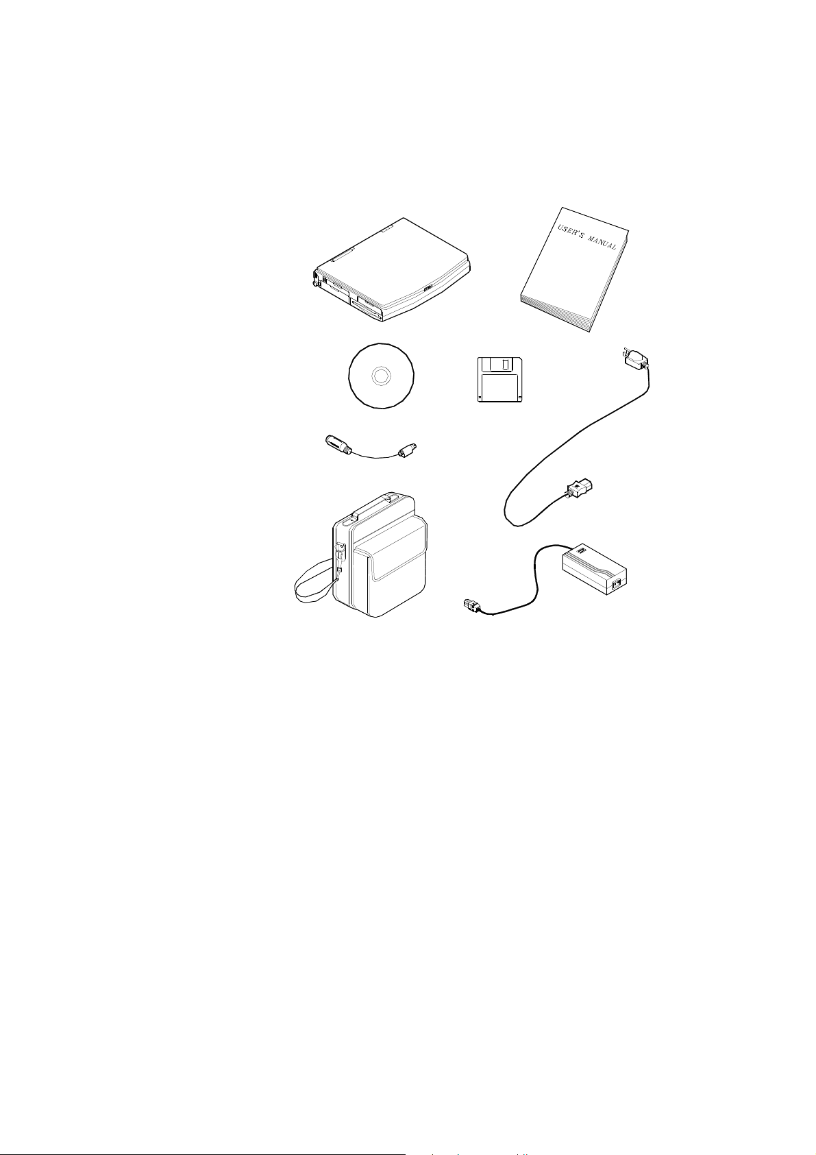
Unpacking
Carefully unpack the Notebook Computer and the included accessories. If there is any
discrepancy or problem, contact your dealer immediately. Be sure to save the packing
materials in case you need to repack and ship the Notebook back in the future.
•
Notebook Computer.
•
Carrying Bag.
•
Power Adapter.
•
Power Cord.
•
User Manual.
•
PS/2 Transfer Cable.
•
Utilities Diskette(s).
•
Compact Disk.
8
Page 9
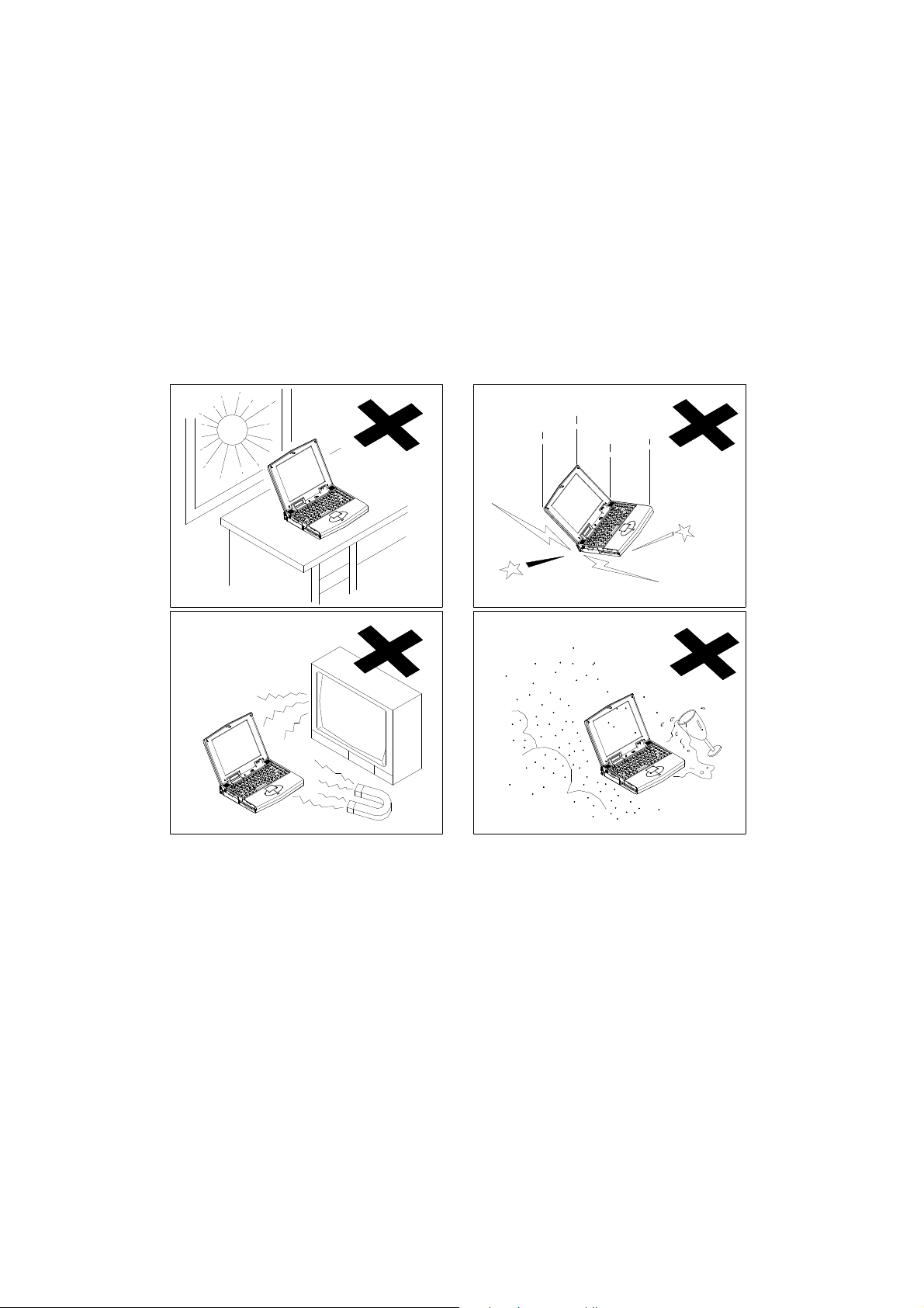
Operating Environment
As with any other precision electronic equipment, proper care and operation of your
Notebook will provide long and reliable service. Be sure the computer system should
not be:
•
Exposed to excessive heat or direct sunlight.
•
Subjected to shock or vibration.
•
Exposed to strong magnetic fields.
•
Left in a place where foreign matter or moisture may enter the system.
9
Page 10
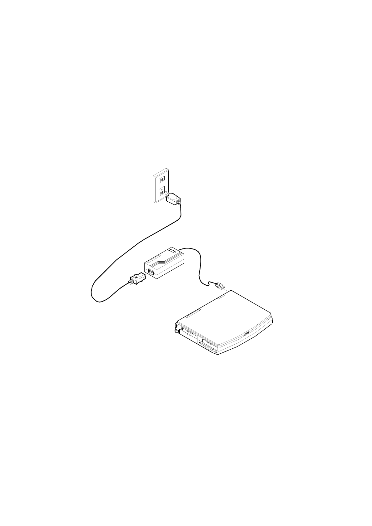
Powering the System
The first time the Notebook is opened, the AC power source should be used since the
internal battery pack (if installed) may have discharged during shipment.
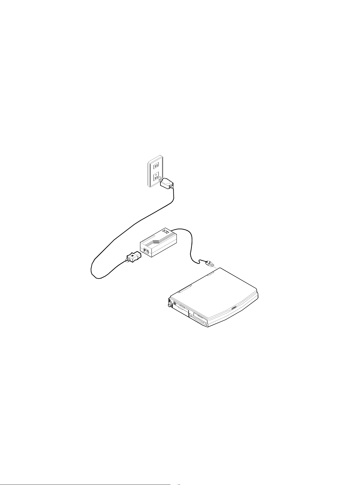
AC Power
Use only the power adapter that comes with your Notebook Computer. System
operation with an incorrect power adapter will cause damage to the Notebook
and its components. Follow these steps when connecting the AC power adapter:
1. Plug the power adapter to the DC socket on the rear of the Notebook.
2. Connect the AC power cord to the power adapter.
3. Plug the AC power cord into a properly grounded outlet.
10
Page 11
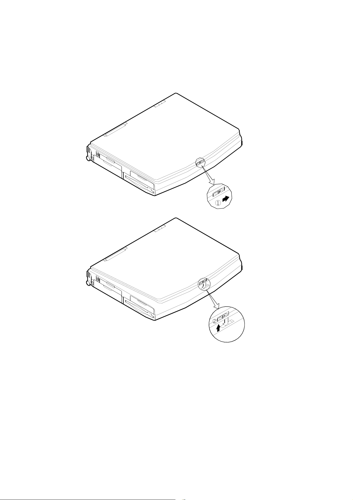
Opening the LCD Cover
1. Slide the top cover latch to the right to release the latch.
2. Lift the top cover to reveal the LCD panel and keyboard.
3. Adjust the LCD panel to a comfortable viewing angle.
11
Page 12

12
Page 13
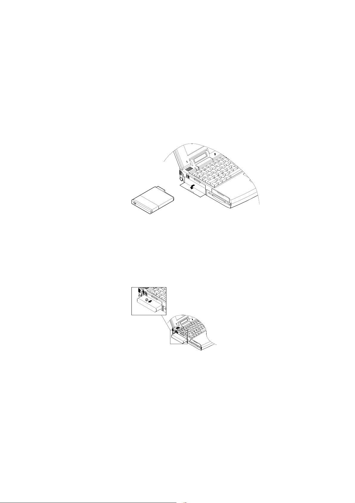
Portable Operation
Primary Battery Pack
The Notebook system can be powered by battery pack for continuous portable
operation without an external power source when you take it away from the office.
However, the actual operating time will be dependent upon the application you use
and the configuration you set.
Inserting
1. Open the battery access door on the left side of the Notebook.
2. Slide the battery into the compartment until the latch clicks into place
3. Close the access door..
Removing
1. Open the access door.
2. Press the battery latch upward to pop up the battery pack.
3. Pull the battery pack out of the compartment.
13
Page 14
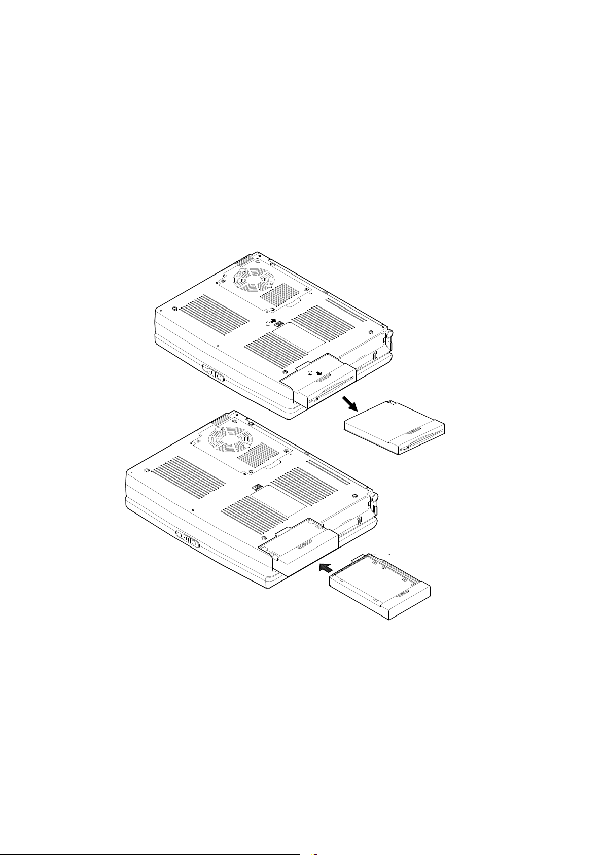
Secondary Battery Pack (Option)
When you need prolonged use without the availability of the AC adapter, you may
consider a spare battery, called Secondary Battery Pack, for optimal portable
operation. Contact your dealer for more information. The Secondary Battery Pack is
designed to reside in the same compartment as that of the floppy diskette drive.
1. Turn the Notebook off.
2. Turn the Notebook over.
3. Locate the FDD (Floppy Diskette Drive) latch.
4. Press the latch in the illustrated direction and pull the floppy diskette drive out of
the compartment.
5. Slide the Secondary Battery Pack all the way into the empty compartment.
14
Remove the Floppy Disk
Insert the Secondary Battery
Page 15
Recharging by AC Power
The system’s battery pack will recharge whenever the system is plugged into the AC
power supply, regardless if the system is being operated or not.
Off-Line Charge The Notebook system is powered off. Connect the AC
adapter to the unit. Its DC output will be used solely to
charge the battery. It will take hours to bring a completely
discharged battery to its full charge state.
Trickle Charge The Notebook system is powered on. Again, make sure the
AC adapter is connected to the unit. Its DC output will both
power the system and charge the battery. It may take more
hours than off-line charge to charge the battery.
15
Page 16
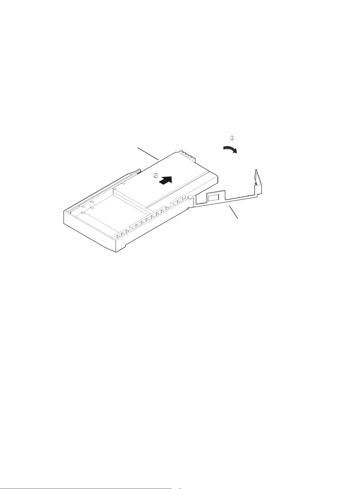
DURACELL Rechargeable Battery Compatible
The Notebook system is compatible with DURACELL rechargeable battery:
DR36 nickel-metal hydride (Ni-MH) rechargeable battery
DR202 Lithium ion (Li-Ion) rechargeable battery
The DURACELL battery comes with a charge indicator button. Simply press the
indicator button to get informed of the reamining battery life. Read its instrtuctions
before using the battery.
You may obtain additional battery from your dealer or retail outlets worldwide. The
Secondary Battery Pack must be inserted into the bracket as shown below:
Battery
Proper Handling of Battery Packs
Do not attempt to disassemble the battery under any circumstances.
The battery may explode if exposed to fire or high temperatures.
Avoid short circuit the battery by the metal terminals (+, −).
16
Bracket
Page 17
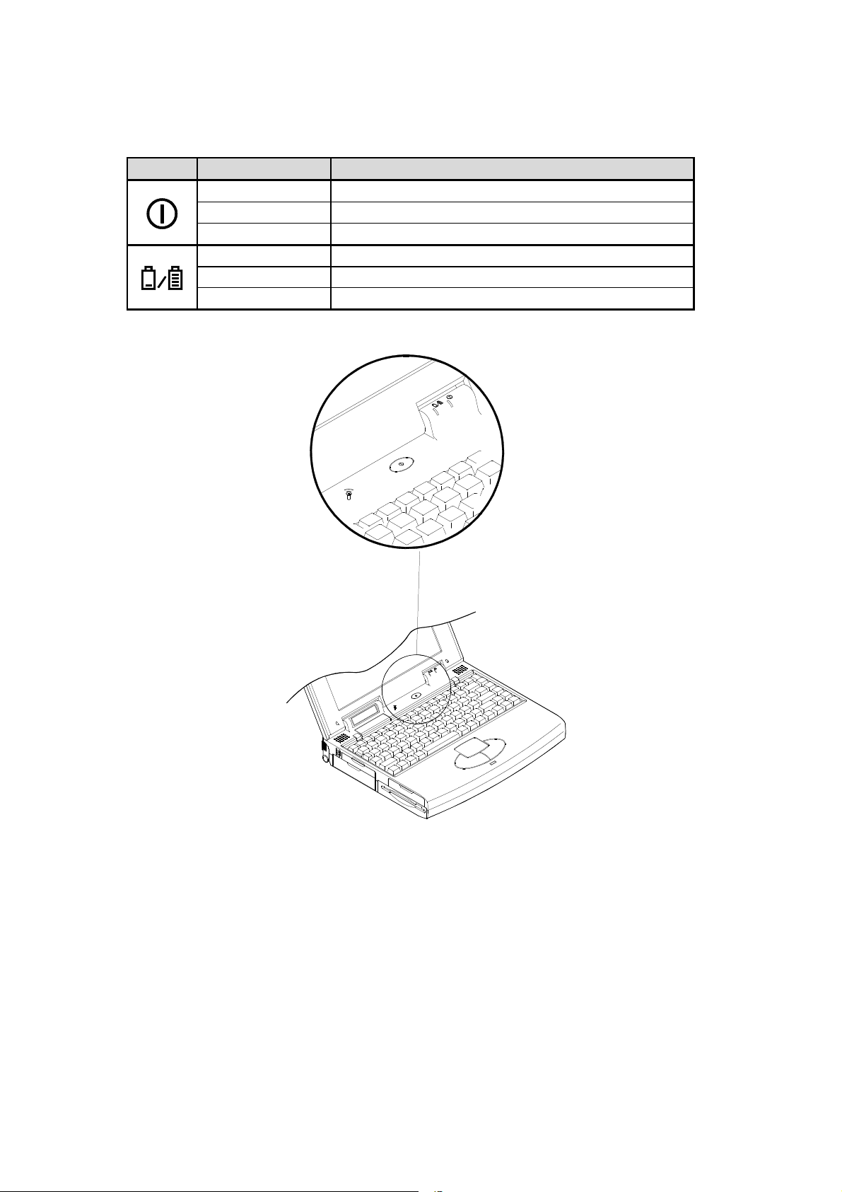
Power Status LED Indicators
The Power Status LED on the top-right corner of the base of the Notebook indicates
the various states of battery and AC power.
Icon Color of Light Status
Green System power on (either by AC or by battery)
Red Battery being charged
Orange Battery being charged while system powered on
Green Primary battery fully charged
Red Secondary battery fully charged
Orange Both batteries fully charged
17
Page 18

Chapter 2
System Overview
This Chapter identifies various features of the Notebook that are important to the
proper operation of the system. It will discuss the following topics:
Identifying all devices and ports.
Identifying the system status LCD bar codes.
Getting familiar with the keyboard.
18
Page 19

Right Side View
Right-Side Stand
Slide this stand outward (together with the left-side stand) to adjust the viewing angle.
When a high speed CPU is installed, erecting the stands on both sides will help
heat dissipation during operation.
Microphone-in Jack
This audio port accepts sound source to record or to playback when externally
connected microphone is used instead of the built-in one.
Line-in Jack
External sound source can be fed into the Notebook through this jack to record or to
playback.
Headphone Jack
Headphone can be attached to the system through this jack, so can external speakers
that have their own built-in output power amplifier.
Infrared
The wireless communications capabilities are based on IrDA (Infrared Data
Association) standards for cordless connection between the Notebook Computer and
an IrDA-compliant device.
PC Card Type III Expansion Slot
The Type III PC Card slot is located inside a flip-down panel. It allows you to
conveniently attach numerous accessories to the Notebook Computer. It is equivalent
to two Type II PC Cards slots. The ejection button for the upper slot is located on the
left. The ejection button for the lower slot is on the right.
CD-ROM Drive
The 5.25” IDE CD-ROM drive uses the tray loading mechanism for ease of use. Press
the ejection button to load the tray from the drive unit.
Ventilation
The Notebook features a ventilation to dissipate the system’s operating heat. Do not
block or obstruct it during operation.
19
Page 20
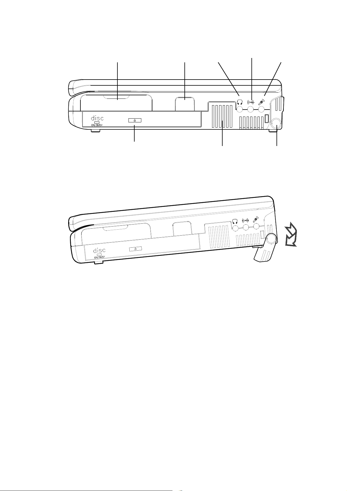
Right
-
side stand
Microphone
-in
Line
-in
Headphon
Infrared
PC card Type III
CD-ROM drive
Ventilation
20
Page 21

Left Side View
Left-Side Stand
Slide this stand outward (together with the right-side stand) to adjust the viewing
angle. When a high speed CPU is installed, erecting the stands on both sides will
help heat dissipation during operation.
Battery Latch
Sliding the battery latch upward will unload the battery pack.
PC Card Type II Slot
The PC Card slot will accommodate a Type II format for system expansion capability.
2.5” Hard Disk Drive
The system’s 2.5” hard disk features a high capacity for data storage providing high
access time for excellent performance.
3.5” Floppy Disk Drive
This is the location of the Notebook Computer’s 3.5” high density 1.44MB floppy
diskette drive. You may press the button on its top-right side for diskette ejection.
Primary Battery Pack
The Notebook Computer’s primary rechargeable battery pack provides the system
with the power for long run time.
21
Page 22
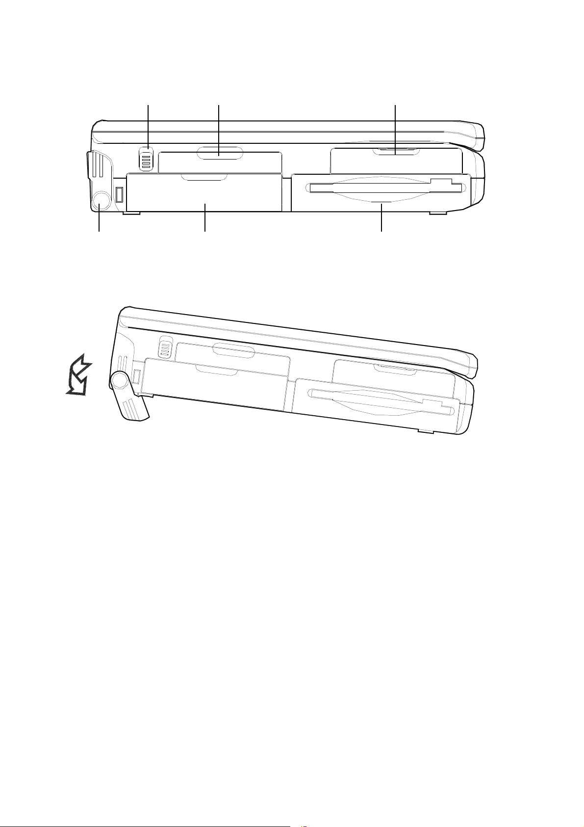
Left-side stand
Primary battery pack
3.5” floppy diskette drive
Battery latch
PC card Type II
2.5” hard disk drive
22
Page 23

Rear View
DC-in Socket
This socket is where the Notebook Computer’s universal AC/DC power adapter is
connected to the system. To disconnect the power adapter, pull the plug (not the cord)
directly back.
Serial Port
This RS233 port is 16C550 compatible to connect an external mouse for example.
Expansion Port
This port is used to connect the proprietary Port Replicator or Docking Station. All of
the features of the Docking Station are available through the plug-in process offering
the Notebook Computer access to a desktop system.
RCA Jack
Use this jack to transmit video signal to a TV set. You may need to select the video
standard (NTSC/PAL) for video display.
External Monitor (CRT) Port
This port allows the connection of an external monitor to the system. It uses a 15-pin
connector and supports super-VGA, and simultaneous display of LCD and CRT.
MIDI/Game Port
This port is used to either connect any MIDI device such as a MIDI instrument or
keyboard, or connect an external standard joystick.
Parallel Port
This is a parallel port to connect a printer for example. It supports EPP (Enhanced
Parallel Port) and ECP (Extended Capabilities Port) modes, but required as well is the
use of the connected parallel device’s software driver.
PS/2 Type Port
An external keyboard is able to be connected to the system via this port. So is an
external PS/2 mouse to the system as another pointing device choice.
23
Page 24

DC-in socket
Serial port
Expansion port
RCA jack
CRT port
MIDI/Game port
P
arallel port
PS/2 port
24
Page 25

Top-Front View
Power Switch
This button is toggled to turn the system on or off.
Microphone
This is a built-in input device for audio system.
LCD Panel
This is the Notebook Computer’s flat panel display. It is VGA compatible and driven
by a PCI local bus controller for high performance.
System Status LCD Bar
The Notebook features the LCD bar which displays the status of various devices. The
symbols defined later will appear on the LCD bar when appropriate.
Dual Stereo Speakers
These are two built-in output devices on each side for audio system.
Trackpad Pointing Device
The pointing device features a sensitive glide pad for precise movements. It functions
like a two-button mouse does. The right trackpad button is equivalent to the right
mouse button; the left trackpad button is equivalent to the left mouse button.
Windows 95 Keyboard
The Notebook utilizes an 86 key Windows 95 keyboard. It is detachable for various
language versions.
25
Page 26

Page 27

LCD panel
Dual stereo speakers
Windows 95 keyboard
Trackpad & buttons
LCD bar
Power button
Microphone
27
Page 28

Icon Indicators in the LCD Bar
The Notebook Computer features a LCD bar to show the current status of your
Notebook by their icon indicators’ on or off states. Each icon is identified with a
symbol defined in the following:
AC Power in Use The system is using AC power for
operation.
Battery Low (Flash) The battery power is reaching a critically
low level.
CD-ROM in Use The CD-ROM drive is being accessed.
FDD in Use The floppy disk drive is being accessed.
HDD in Use The hard disk drive is being accessed.
Suspend to Memory The system has entered the Suspend to
DRAM Mode.
Turbo Speed The CPU is running at the maximum
speed.
Scroll Lock The scroll lock function is activated.
Caps Lock The caps lock function is activated.
NumLock The embedded numeric keypad function is
locked.
28
Page 29

29
Page 30

The Keyboard
The Notebook Computer utilizes an 86 key keyboard detachable for various language
versions. It is laid out slightly differently from a standard AT keyboard, but it offers
all of the same functions plus some special specific features of the system.
30
Page 31

Chapter 3
System Operating
This chapter shows how to access and change various hardware components. The
following topics will be discussed:
Upgrading processors.
Expanding memory.
Configuring TV-output.
Using embedded numeric keypad.
Using Fn key. (Cursor Contol Keys, Numeric Keypad, Hot Keys)
Using storage drives (hard disk, floppy disk, CD-ROM).
Using PC Card sockets.
31
Page 32

Upgrading CPU
Before you begin working with any internal components of the Notebook,
removal all batteries and disconnect the AC power adapter.
Make sure that you wear an anti-static wrist strap to ground yourself before
working with any internal components of the Notebook. Static electricity may
damage components beyond repair.
The system is capable of hosting a wide range of Intel processor’s speed and voltage,
providing users with a Zero-Insertion-Force (ZIF) socket to facilitate removal and
installation of CPUs.
32
Page 33

Setting CPU Speed
P54C/LM
75 90
100 120 133 150 166 200
P55C
233
150 166 200
S2-1 Off On Off On
Off On Off Off
S2-2 On Off Off Off Off Off Off Off
S2-3 Off
S2-4 Off
S2-5 Off Off Off On On On On Off
S2-6 Off Off Off Off Off On On On
6x86LV
P150+
P166+
S2-1 On Off
S2-2 Off
S2-3 On
S2-4 Off
S2-5 On
S2-6 Off
S2-2 Off Off Off Off Off Off
S2-3 Off Off Off Off Off Off
S2-4 Off Off Off On On On
S2-5 On On On On On On
S2-6 Off On On Off On On
1. Turn the Notebook PC over.
2. Remove the CPU cover.
3. Remove the two screws that fasten the bracket mounted on the heat sink.
4. Remove the four screws that fasten the heat sink mounted on the CPU.
5. Locate the DIP Switch S2 to set the proper configuration for CPU frequency.
Intel
Cyrix
AMD
K5/PR133 K5/PR150 K5/PR166 K6/266AFR K6/300AFR K6-2/300AFR
S2-1 Off On Off Off Off Off
33
Page 34

Setting CPU Power
S2
Find the 4-pole DIP Switch on the CPU Power Module to set the power voltage of
the CPU you just installed for 2.2V, 2.45V or 2.8V, unless what you have is the
other type of CPU Power Module which is only for 3.3V. Refer to the user guide of
the installed CPU to make sure which power voltage you should set. Incorrect setting
will cause damage to both the system and the CPU.
The back side of heat sink (
Thermal pad
1 2 3 4 CPU Power
On Off Off Off 2.2 V
Off On Off Off 2.45 V
Off Off On Off 2.8 V
Washer for AMD K6 only
Washer
)
Heat Sink
CPU Power Module
34
Set for CPU power
Set for CPU speed
Page 35

ZIF Socket Operation
A ZIF (Zero Insertion Force) socket is provided to facilitate CPU removal and
installation for you. You may need to contact your dealer for the proprietary tool
to work with the ZIF socket. Improper tool or incorrect operation may damage
the socket.
Insert the proprietary tool into the
OPEN position of the ZIF socket. Move
the screwdriver to the right to unlock the
CPU.
Align the index corner to install the CPU in
place.
Insert the proprietary tool into the CLOSE
position of the ZIF socket and lever to the left
to lock the CPU.
Index corner
35
Page 36

Expanding Memory
The system has two memory sockets for different RAM Modules to expand the
memory up to 72MB. These RAM Modules are 144-pin SODIMM (Small Outline
Dual In-line Memory Module) type. With the following memory configurations, the
total memory size will be automatically detected by the POST routines:
64-bit Bank 0 64-bit Bank 1 Power Speed RAM Size
(1Mx16)x4 None 8MB
None (1Mx16)x4 8MB
(1Mx16)X4 (1Mx16)x4 16MB
(1Mx16)X8 None 16MB
None (1Mx16)X8 16MB
(2Mx8)x8 None 16MB
None (2Mx8)x8 16MB
(1Mx16)X8 (1Mx16)x4 24MB
(1Mx16)X4 (1Mx16)X8 24MB
(1Mx16)X8 (1Mx16)X8 32MB
(4Mx4)X16 None 5V 70ns 32MB
None (4Mx4)x16 32MB
(2Mx8)x8 (2Mx8)x8 32MB
(2Mx8)x8 (1Mx16)X8 32MB
(1Mx16)X8 (2Mx8)x8 32MB
(2Mx8)x16 None 32MB
None (2Mx8)x16 32MB
(4Mx4)x16 (1Mx16)X4 40MB
(1Mx16)x4 (4Mx4)x16 40MB
(4Mx4)x16 + (1Mx16)x4 None 40MB
(2Mx8)x16 (2Mx8)x8 48MB
(2Mx8)x8 (2Mx8)x16 48MB
(4Mx4)x16 + (1Mx16)x4 (1Mx16)X4 48MB
(4Mx4)x16 + (1Mx16)x4 (1Mx16)X8 56MB
(4Mx4)x16 (4Mx4)x16 64MB
(4Mx4)x16 + (1Mx16)x4 (4Mx4)x16 72MB
36
Page 37

1. Remove the access door located in front of the System Status LCD Bar by sliding
it towards the front.
2. Press the two keyboard latches so that the keyboard can be elevated from its
normal position.
37
Page 38

3. Carefully lift the keyboard assembly out so that the SODIMM sockets are
exposed.
Bank 0
Bank 1
Installing the SODIMM
1. Locate the notch on the left side of the SODIMM.
2. With the notched end of the SODIMM toward the left side of the socket, insert
the SODIMM at an angle of approximately 20° into the socket; then press it
firmly toward the socket.
3. Pivot the SODIMM until it snaps into place.
Removing the SODIMM
1. Press out on the latches on both edges of the socket at the same time to release the
SODIMM.
2. The SODIMM may pop up to detach from the socket.
3. Remove gently the SODIMM.
38
Page 39

Configuring TV-Output
The Notebook is equipped to output video signals to a TV set through the RCA jack.
Different countries use different TV broadcast standards. A TV set must comply with
the appropriate standard to properly receive broadcast signals. In the Unites States, TV
sets are built to comply with the NTSC standard. Many countries in Europe and Asia
use the PAL standard. You should refer to your TV user guide to make sure which TV
standard you are using.
TV-output capabilities allow display of realistic game, video, and multimedia on the
large-screen TV. The Notebook uses hardware filtering technologies to reduce flicker
for qualified presentation.
NTSC PAL
S1-1
S1-2
S1-3
S1-4
On Off
Off On
On Off
Off On
39
S1
Page 40

Using the Fn Key
Located on the bottom-left edge of the Notebook Computer keyboard is the Fn key. It
is a special key only found on the Notebook Computer and it is used for operation of:
•
The PgUp, PgDn, Home, End keys.
•
The Embedded Numeric Keypad.
•
The Hot Keys.
PgUp, PgDn, Home, End Keys
Four cursor control keys, also called Arrow or Direction keys,
are located below the Enter key. The colored function will
need to be used with the system function key. Hold the Fn
key, then press one of the four keys.
Home
PgUp
PgDn
End
40
Page 41

Embedded Numeric Keypad
The colored keys in the middle of the keyboard are capable of providing numeric
keypad functions. Follow the easy steps to access the Numeric Keypad:
•
Press the NumLock key to lock the numeric keypad.
•
Notice if the NumLock indicator turned on the system status LCD bar.
•
Press the Fn key along with the specified keys to operate the Numeric Keypad.
41
Page 42

Hot Keys
Located on the bottom-left edge of the keyboard layout is a colored Fn key. It is a
special key only found on the Notebook to make key combination with other keys for
easy access to system features. Hold down the Fn key while pressing other key as
below:
The display may not completely fill the entire LCD screen. This Hot Key
will stretch the display to fill the entire viewing area of the LCD screen.
F6
CRT/LCD
The Hot Key allows you to switch the display among the LCD panel only,
external monitor only, LCD and external monitor simultaneously, or TV
only.
The Hot Key decreases the LCD screen brightness.
The Hot Key increases the LCD screen brightness.
The Hot Key will reduce the volume of the built-in speakers.
The Hot Key will increase the volume of the built-in speakers.
The Hot Key will save the contrast and brightness levels for the LCD panel.
The Hot Key will put the system in a suspend state to save power. This is
especially useful when the AC adapter is not in use so that the battery life
may be maximized.
42
Page 43

Using Hard Disk Drive
The hard disk drive can be removed since it is mounted on a removable tray. This tray
can house 2.5” IDE hard disk drive with a height of 12.7mm or less. The BIOS
supports drives with capacities greater than 528MB through the Logical Block
Addressing (LBA) mode. The System Configuration Utility that is included with the
BIOS can be used to configure the system to accept different drives.
Removing
1.
1. Make sure the system is powered off.
1.1.
2. Open the hard disk drive door on the left side of the Notebook.
3. Pull gently and firmly the hard disk away from the compartment.
43
Page 44

Working with Hard Disk Drive Tray
The hard disk drive is contained within a tray. Two screws on each side of the tray
need to be removed so that the hard disk drive can be taken out of the tray to replace
with another one. The location of the two screws may be various depending on
different hard disk models. When removing the hard disk drive from the tray, be
carefully when disconnecting the cable from the hard disk drive not to bend any pins
or “crimp” the cable.
Inserting
When inserting the hard disk back into the Notebook, be sure to firmly seat the hard
disk drive tray into the compartment. You will feel the tray “click” into position when
it is seated properly.
44
Page 45

Using Floppy Disk Drive
The Notebook comes standard with a 1.44MB, 3.5” floppy disk module. It is labeled
drive A: and may be used as a boot drive if properly set in the System Configuration
Utility. The compartment that the floppy disk currently resides may be replaced with
the Secondary Battery Pack as discussed in Chapter 1.
Inserting/Removing Diskettes
With the label side up, and the metal shutter toward the disk drive, gently insert
the diskette into the drive until the diskette is properly seated.
To remove the diskette from the drive, press the ejection button on the top-right
side of the drive and remove the diskette.
45
Page 46

Using CD-ROM
The Notebook comes standard with a 5.25” CD-ROM that is internally mounted. It is
labeled drive D:
Do not disassemble the CD-ROM from the Notebook. Only certified technicians
should perform repairs to the CD-ROM.
To insert a CD, press the Eject Button and place the CD on the Disc Tray label side
facing up. Push the CD tray in, and you are ready to get started. The Busy Indicator
will light up while data is accessed or audio is playing. When system power is
unexpectedly interrupted, insert an instrument such as a straightened paper clip into
the Emergency Eject Hole to manually eject the tray.
Disk Tray
46
Emergency Eject Hole
Eject Button
Busy Indicator
Page 47

Using PC Card Sockets
The Notebook provides system expanding capabilities with three PC card sockets
(previously referred to as PCMCIA) by inserting various PC cards. All sockets support
5V/3.3V 16-bit PC cards. Two sockets are available in the right-side panel and one in
the left side. The lower socket on the right-side panel is ZV (Zoomed Video) capable.
The PC cards may be LAN, fax/modem, communication devices, or expanded
memory. PC cards have three types: Type I measures 3.3mm thick; Type II 5.0mm;
and Type III 10.5mm. You may accordingly use two Type II PC cards or one Type III
PC card with the 68-pin connector in the right-side sockets.
Inserting and Removing PC Cards
•
To insert a PC Card, align the card with the slot and push it firmly until it locks
into place.
47
Page 48

•
To remove a PC Card, press the appropriate eject button and the card will be
ejected from its slot.
A Socket A
B Socket B
C Eject button for Socket A
D Eject button for Socket B
D B
A C
Socket C and the eject button
Configuring PC Cards
The Notebook is configured to accept PC Cards. However, most cards require
additional software drivers to be loaded at the time of installation. These drivers are
usually provided by the manufacturers of the PC Cards on diskettes. Follow the
installation instructions that accompany the specific PC Card you are using.
48
Page 49

Chapter 4
BIOS Utilities
The Notebook Computer has several built-in software utilities to help you get the
most from the system hardware. This chapter discusses:
The Power-On-Self-Test (POST).
The System Configuration Utility (SCU).
Power On Self Test (POST)
The BIOS performs a series of power-on-self-test (POST) to diagnose hardware errors
when the system first starts up. During the POST procedure, the POST verifies that
the hardware is installed and operational. If a hardware problem exists, the POST
routine may halt execution (depending upon the severity of the problem).
49
Page 50

POST Messages - Normal Operation
If no configuration errors are detected, the system will be operated after the POST
process is completed.
You may press the Spacebar key to skip the memory test.
System PCI BIOS for SiS-510X Version 1.01.26
Copyright 1983 - 1996 SystemSoft Corp. All Right Reserved.
System Processor: 200 MHz Intel Pentium CPU
System External Cache: 256 KB Enabled
Video Chip: Trident Cyber 9385 with 2 MB Video RAM
SystemSoft Plug-n-Play BIOS Ver 1.0a
Base Memory 640 Kb
Extended Memory 39936 Kb
Shadow Memory 256 Kb
Reserved Memory 128 Kb
Total Memory 40960 Kb
<CTRL-ALT-S> to enter System Configuration Utility
50
Page 51

POST Messages - Error Detected
If a configuration is detected as a non-fatal error, a WARNING message will be
displayed. You should either press F1 key to continue, or press Ctrl-Alt-S key
combination to enter the System Configuration Utility.
System PCI BIOS for SiS-510X Version 1.01.26
Copyright 1983 - 1996 SystemSoft Corp. All Right Reserved.
System Processor: 200 MHz Intel Pentium CPU
System External Cache: 256 KB Enabled
Video Chip: Trident Cyber 9385 with 2 MB Video RAM
SystemSoft Plug-n-Play BIOS Ver 1.0a
Base Memory 640 Kb
Extended Memory 39936 Kb
Shadow Memory 256 Kb
Reserved Memory 128 Kb
Total Memory 40960 Kb
WARNING - NO BOOTABLE FLOPPY DRIVE 0 INSTALLED
WARNING - FLOPPY INFORMATION INVALID - RUN SCU
<CTRL-ALT-S> to enter System Configuration Utility or Press F1 to Continue
51
Page 52

System Configuration Utility (SCU)
The System Configuration Utility (SCU) is a ROM-based configuration utility that
displays the system’s configuration status and provides users with a tool to set their
system parameters. The settings are stored in non-volatile battery-backed CMOS
RAM which saves the information even when the power is turned off, and retains that
when the system is turned back on.
Invoking the System Configuration Utility
The System Configuration Utility (SCU) will be accessed when simultaneously press
the Ctrl, Alt, and S keys.
< CTRL-ALT-S > to enter System Configuration Utility
The above message only lasts seconds. If you miss it, the computer will access its boot
process. You must reboot the system and try again within the time limit if you like to
enter the System Configuration Utility.
52
Page 53

Working with the Menu Bar of System Configuration Utility
Mouse right button
Press simultaneously the Ctrl-Alt-S key combination to enter the menu bar of the
System Configuration Utility.
Action Keys Used Description
Activate menus Alt Activate the System
Configuration Utility.
Select menu bar item
The highlighted letter key Move to the correspondent
Accept menu bar item Mouse left button
Cancel current action
Left arrow (←)
Right arrow (→)
Spacebar
Enter
Esc
Move to a menu bar item on
the left.
Move to a menu bar item on
the right.
menu bar item.
Enter the selected menu bar
item to configure settings.
Undo the current command.
53
Page 54

Working with the Pull-Down Menu of System Configuration Utility
When the desired menu bar item is highlighted, press the Enter key to enter the pulldown menu for values setting.
Action Keys Used Description
Select pull-down menu item
The highlighted letter key Move to the correspondent
Select a control Tab Move between the options.
Change values
Accept entries Spacebar Enable/disable the specified
Enter Choose <OK> from a list of
Reject entries Esc Undo the current setting.
Enter Choose <Cancel> from a list
Activate accelerators Alt Invoke all the highlighted
Quit Esc Press the Esc key to close the
Down arrow (↓)
Up arrow (↑)
Down/Up arrows (↓)(↑)
Move to the next pull-down
menu item.
Move to the previous pulldown menu item.
pull-down menu item.
Modify the settings.
function. When a check mark
appears, the function is on.
options.
of options.
letters corresponding to their
respective options.
pull-down menu.
54
Page 55

Features of the System Configuration Utility
System Menu
Clicking an option will enable the specific capability.
Item Setting Function
Date and Time Day/month/year
Hour/minute/second
Fast Boot Initializes and quickly boot the
Enable Pointing Device Enables the internal trackpad.
Boot Device Diskette A Specifies where the system
Hard disk C boots from.
Video Display LCD and CRT Enables both LCD and CRT
Auto sense The display auto-switches to CRT if
Video Expansion
Enabled
Set Boot Password Enter old password You may enter a password up
Enter new password to 10 printable alphanumeric
Verify new pasword characters.
Enable Booting
Set Setup Password Enter old password You may enter a password up
Enter new password to 10 printable alphanumeric
Verify new pasword characters.
Enable Setup password Verifies the password every time
Enables the LCD expanded mode.
password
Sets the current date and time.
system in a few seconds by passing
certain diagnostic tests.
simultaneously.
one is sensed.
Verifies password every time the
system is booted.
you try to enter SCU.
55
Page 56

56
Page 57

Devices Menu
Clicking an option will enable the specific capability.
Item Setting Function
Diskette Drive None Specifies a drive type
1.44MB for diskette drive A.
Hard Disk Disk Type None No hard disk is installed in the
system.
Custom Modifies the values for
cylinders, heads, sectors per
track, landing zone, write
precomposition and size (MB).
Auto-ID Automatically configures the
hard disk parameters for any
supported IDE drive.
Enhanced Options LBA mode Enables Logical Block Address
(LBA) mode to overcome
528MB barrier.
Multiple
sector mode
Fast PIO
mode
COM Ports COM A settings None Specifies the COM A
3F8H, IRQ4 configuration.
2F8H, IRQ3
3E8H, IRQ4
2E8H, IRQ3
COM B settings None Specifies the COM B
3F8H, IRQ4 configuration.
2F8H, IRQ3
3E8H, IRQ4
2E8H, IRQ3
COM B definition Serial port 2 Defines COM B hardware.
IrDA (HPSIR)
IR (ASKIR)
FIR
Enables multiple sector mode
to increase sequential data
transfers.
Enables Fast Programmed
Input/output (PIO) mode for
high data transfer rate.
57
Page 58

Item Setting Function
LPT Port Port setting None Specifies the LPT
378H port configuration.
278H
3BCH
Port definition SPP mode Standard Parallel Port.
EPP mode Enhanced Parallel Port.
ECP mode Extended Capabilities Port.
IRQ setting IRQ5 Specifies IRQ
IRQ7 configuration.
ECP DMA setting DMA1 Specifies ECP DMA
DMA3 configuration.
Audio Port Port setting 220H Specifies the system’s
230H audio I/O port address.
240H
250H
IRQ setting IRQ9 Specifies the system’s
IRQ5 audio IRQ configuration.
IRQ7
IRQ10
DMA setting DMA0 Specifies the system’s
DMA1 audio DMA channel
DMA3 configuration.
MIDI Port MIDI port 300H Specifies the system’s
310H General MIDI I/O port
320H address.
330H
Wave Table
Enabled
Keyboard
Numlock
Enables Wave Table
synthesizer.
Specifies NumLock is on at
system boot time.
58
Page 59

Item Setting Function
Keyboard Repeat Key repeat rate 2 cps Defines the rate
6 cps (character per second)
10 cps at which the keyboard
15 cps repeats while a key is
20 cps depressed.
30 cps
Key delay ¼ sec Specifies the time
½ sec (second) that will pass
¾ sec after a key is depressed
1 sec before starts to repeat.
Keyboard
Overlay
Sets the NumLock equals Pad
Lock flag. All keypad keys will
download their overlay legend
while pressed.
59
Page 60

Power Menu
Clicking an option will enable the specific capability.
Item Setting Function
Power Management Power saving
mode
Battery only Enables the system’s
Always on Enables the system’s
Power saving
level
Medium battery
High battery saving Enables the power
Video Monitoring Video RAM access will
Disabled Disables the system’s
power saving features.
power saving features
only during battery
operation.
power saving features
during either battery or
AC operation.
Low battery saving Enables the power
saving to its lowest
which results in
maximum performance
but shortest battery life.
Enables the power
saving
saving to its medium
which results in
moderate performance
and battery life.
saving to its highest
which results in
minimum performance
but longest battery life.
prevent the system from
entering a standby
mode.
60
Page 61

Item Setting Function
Resume minute
Suspend Controls Battery weak Flash beeping The warning icon
flashes on the LCD bar
and emits a series of the
audio beeps.
Suspend system Automatically suspends
the system upon a low
battery condition.
Flash only The warning icon
flashes on the LCD bar.
Suspend mode Suspend to memory Specifies the suspend
mode as 5-volt suspend
mode.
Suspend to disk Specifies the suspend
mode as 0-volt suspend
mode.
Modem ring resume
Set resume alarm Resume hour
Resumes the system
from suspend-tomemory mode when a
modem ring is detected.
Sets the time to resume
the system from
suspend-to-memory
mode.
61
Page 62

Exit Menu
Clicking an option will enable the specific capability.
Item Function
Save and Reboot Saves the current settings and reboots the system.
Exit (No Save) Exits the SCU without saving any of the current changes.
Default Settings Changes the current setup to the system default values.
Restore Settings Restores the current setup to the original custom values.
Version Information Displays the current BIOS version information.
62
Page 63

Chapter 5
Power Management
The Notebook provides you with several ways to manage its power consumption
while maintaining system performance. This chapter discusses the following topics:
Advanced Power Management (APM).
Power Management settings in the System Configuration Utility (SCU).
63
Page 64

Advanced Power Management (APM)
The Notebook provides built-in Advanced Power Management (APM 1.2) support to
reduce power consumption. The functionality of APM varies depending on the
operating system you are using. Some operating systems do not support APM, such as
Windows NT, and therefore, cannot take advantage of the system’s capabilities in this
area.
Power Management Settings in the SCU
The Notebook has power management settings within the SCU so that the power
consumption can be minimized while maintaining optimal system performance.
Standby Mode
Standby Mode is the device level power management. Most controllable peripheral
devices such as the hard disk and the LCD display will be powered off. Standby Mode
is discontinued when any system activity is detected, such as a key being pressed on
the keyboard. The system will not enter Standby Mode if the Video Monitoring
option is enabled under Power Menu in the SCU.
Windows 95 will repeated scan the CD-ROM IDE port unless configured otherwise.
This will prevent the system from entering Standby Mode. To disable this setting in
Windows 95, perform the following steps:
•
Enter Control Panel.
•
Select the System icon.
•
Select the Device Manager folder.
•
Select CD-ROM.
•
Select Settings.
•
Remove the “” from Auto insert notification.
64
Page 65

Suspend Mode
Suspend Mode is the system level power management. The CPU and DMA clocks
will be halted and all controllable peripheral devices will be powered off. The
Notebook system can be placed into two different suspend modes:
Suspend to Memory
Suspend to Disk
Suspend to Memory
Suspend to Memory is also known in a more technically descriptive term as “5-volt”
Suspend Mode since it requires 5-volt of power when the system is in “Suspend”
state.
When Suspend to Memory is activated, you will notice that the system exhibits the
same characteristics as if you powered the system off. You will notice that the LCD
Bar is still active, and the Suspend to Memory indicator is apparent. Suspend to
Memory may be activated by the following events:
•
Suspend hot key (Fn + Esc)
•
Battery weak (SCU setting)
The Notebook system may resume from Suspend to Memory by the following events:
•
Resume alarm time (SCU setting)
•
Modem ring (SCU setting)
•
Any keyboard key pressed
65
Page 66

Suspend to Disk
Suspend to Disk is also known in a more technically descriptive term as “0-volt”
Suspend Mode since it does not require any power when the system is in “Suspend”
state.
Before Suspend to Disk may be used, a non-DOS partition has to be created on the
hard disk drive. Follow the instructions below:
1. Use your operating system’s FDISK program to delete all partitions of the hard
disk if any already exists on the target drive.
2. Boot the system from the A: drive and run the 0VMAKFIL.EXE Utility to create
the Suspend to Disk partition on the hard disk whose size will accommodate the
installed DRAM (n) plus 2MB integrated video RAM.
A:\>0VMAKFIL /Pn
For example, if the system DRAM is 72MB, 0VMAKFIL will create a partition of
size greater than 74MB.
A:\>0VMAKFIL /P72
Note: Rewrite the sector signatures if you partition again the very hard disk.
C:\>0VMAKFIL /PW
3. Re-partition the hard disk using your operating system’s FDISK program.
When Suspend to Disk is activated, information will be written to the non-DOS
partition which was created by the above mentioned command, and the system will
then power off. Suspend to Disk may be activated by the following events:
•
Suspend hot key (Fn + Esc)
•
Battery weak (SCU setting)
The system can be returned from exactly where it was suspended when a resume event
occurs. However, the system may not resume successfully from the Suspend Mode
when connected to some external devices, such as PC Card. The system may resume
from Suspend to Disk by the only event:
•
Power (back) on
66
Page 67

Appendix A
Specifications
CPU
Intel Pentium 75/90/100/120/133/150/166/200/233MHz
Cyrix 6x86LV P150+/P166+.
AMD K5 PR133/PR150/PR166.
Memory
5V power supply.
512KB secondary synchronous cache.
8MB expandable up to 72MB.
144-pin SODIMM package.
System BIOS
256KB flash ROM.
PCI 2.1.
Plug and Play 1.0a.
Display
10.4”/11.3”/12.1” TFT SVGA (800x600 pixels) LCD available.
12.1” DSTN SVGA (800x600 pixels) LCD available.
2MB display memory.
Video Port Manager (VPM) for Zoomed Video (ZV) port.
Simultaneous display with an external monitor.
Input/Output
Built-in trackpad.
Serial port.
Parallel port.
CRT port.
PS/2 type port.
RCA jack.
Expansion port.
Game port.
Headphone jack.
Microphone-in jack.
Line-in jack.
PC Card Sockets
67
Page 68

Type II x3, or Type II x1 + Type III x1.
One ZV-capable socket.
Storage Drives
2.5” hard disk, transfer rate up to PIO Mode 4.
3.5” floppy disk, high density 1.44MB.
5.25” CD-ROM, IDE interface.
Infrared Wireless Communication
IrDA.
ASKIR.
FIR.
Audio
Sound Blaster Pro compatible.
Microsoft Windows sound system compatible.
MPU-401 and General MIDI compatible.
FM and Wave Table synthesizer.
Built-in microphone.
Built-in dual speakers.
Power Management
Standby Mode.
Suspend to Memory.
Suspend to Disk.
APM 1.2.
Rechargeable Battery Pack
Ni-MH 12V available.
Li-Ion 10.8V available.
Battery low warning.
Auto-switching with AC power adapter.
Secondary Battery Pack (option).
AC/DC Power Supply
AC input: 100∼240VAC, 47∼63Hz.
DC output: 20V.
Charger output: 12V
Total output: 50W.
External Model: AC-D01
Alternative Model: F1650L
68
Page 69

Keyboard
Windows 95
Detachable for various language versions
Size & Weight
302mm(w) x 234mm (d) x 54mm (h)
3.4 kg
Temperature Environment
Operating 10°∼35°C
Storage -10°∼60°C
Humidity Environment
Operating 20%∼80%, non-condensing
Storage 10%∼90%, non-condensing
69
Page 70

Appendix B
Pin Assignment
Serial Port
Pin Signal
1 DCD (DATA Carrier Detect)
2 RXD (Received Data)
3 TXD (Transmitted Data)
4 DTR (Data Terminal Ready)
5 GND (Signal Ground)
6 DSR (Data Set Ready)
7 RTS (Request To Send)
8 CTS (Clear To Send)
9 RI (Ring Indicator)
Parallel Port
Pin Signal Pin Signal
1 Strobe# 14 Auto Linefeed#
2 Data 0 15 Error#
3 Data 1 16 Initialize#
4 Data 2 17 Select In
5 Data 3 18 Ground
6 Data 4 19 Ground
7 Data 5 20 Ground
8 Data 6 21 Ground
9 Data 7 22 Ground
10 ACK# 23 Ground
11 Busy 24 Ground
12 Paper Empty 25 Ground
13 Select
70
Page 71

Monitor Port
Pin Signal Pin Signal Pin Signal
1 BRED 6 GND 11 N.C
2 BGREEN 7 GND 12 DDCDATA
3 BBLUE 8 GND 13 BHSYNC
4 N.C 9 N.C 14 BVSYNC
5 GND 10 GND 15 DDCCLK
PS/2 Type Port
RCA Jack
Pin Signal
1 KBD-DATA
2 MUS-DATA
3 GND
4 VCC
5 KBD-CLK
6 MUS-CLK
Pin Signal
1 Video-in
2 GND
Game Port
Pin Signal Pin Signal
1 VCC 9 VCC
2 SWA 10 SWC
3 TA 11 TC
4 GND 12 MSO
5 GND 13 TD
6 TB 14 SWD
7 SWB 15 MSI
8 VCC
71
Page 72

PC Card Sockets
Socket A:
Pin Signal Pin Signal
1 GND 35 GND
2 A-CD3 36 A-CD1#
3 A-CD4 37 A-CD11
4 A-CD5 38 A-CD12
5 A-CD6 39 A-CD13
6 A-CD7 40 A-CD14
7 A-CE1# 41 A-CD15
8 A-CA10 42 A-CE2#
9 A-OE# 43 A-VS1
10 A-CA11 44 A-IORD#
11 A-CA9 45 A-IOWR#
12 A-CA8 46 A-CA17
13 A-CA13 47 A-CA18
14 A-CA14 48 A-CA19
15 A-WE# 49 A-CA20
16 A-RDYBY# 50 A-CA21
17 A-VCC-C 51 A-VCC-C
18 A-VPP 52 A-VPP
19 A-CA16 53 A-CA22
20 A-CA15 54 A-CA23
21 A-CA12 55 A-CA24
22 A-CA7 56 A-CA25
23 A-CA6 57 A-VS2
24 A-CA5 58 A-RESET
25 A-CA4 59 A-WAIT#
26 A-CA3 60 A-INPACK
27 A-CA2 61 A-REG#
28 A-CA1 62 A-BVD2#
29 A-CA0 63 A-BVD1#
30 A-CD0 64 A-CD8
31 A-CD1 65 A-CD9
32 A-CD2 66 A-CD10
33 A-WP# 67 A-CD2#
34 GND 68 GND
72
Page 73

Socket B:
Pin Signal Pin Signal
1 GND 35 GND
2 B-CD3 36 B-CD1#
3 B-CD4 37 B-CD11
4 B-CD5 38 B-CD12
5 B-CD6 39 B-CD13
6 B-CD7 40 B-CD14
7 B-CE1# 41 B-CD15
8 B-CA10 42 B-CE2#
9 B-OE# 43 B-VS1
10 B-CA11 44 B-IORD#
11 B-CA9 45 B-IOWR#
12 B-CA8 46 B-CA17
13 B-CA13 47 B-CA18
14 B-CA14 48 B-CA19
15 B-WE# 49 B-CA20
16 B-RDYBY# 50 B-CA21
17 B-VCC-C 51 B-VCC-C
18 B-VPP 52 B-VPP
19 B-CA16 53 B-CA22
20 B-CA15 54 B-CA23
21 B-CA12 55 B-CA24
22 B-CA7 56 B-CA25
23 B-CA6 57 B-VS2
24 B-CA5 58 B-RESET
25 B-CA4 59 B-WAIT#
26 B-CA3 60 B-INPACK
27 B-CA2 61 B-REG#
28 B-CA1 62 B-BVD2#
29 B-CA0 63 B-BVD1#
30 B-CD0 64 B-CD8
31 B-CD1 65 B-CD9
32 B-CD2 66 B-CD10
33 B-WP# 67 B-CD2#
34 GND 68 GND
73
Page 74

Socket C:
Pin Signal Pin Signal
1 GND 35 GND
2 C-CD3 36 C-CD1#
3 C-CD4 37 C-CD11
4 C-CD5 38 C-CD12
5 C-CD6 39 C-CD13
6 C-CD7 40 C-CD14
7 C-CE1# 41 C-CD15
8 C-CA10 42 C-CE2#
9 C-OE# 43 C-VS1
10 C-CA11 44 C-IORD#
11 C-CA9 45 C-IOWR#
12 C-CA8 46 C-CA17
13 C-CA13 47 C-CA18
14 C-CA14 48 C-CA19
15 C-WE# 49 C-CA20
16 C-RDYBY# 50 C-CA21
17 C-VCC-C 51 C-VCC-C
18 C-VPP 52 C-VPP
19 C-CA16 53 C-CA22
20 C-CA15 54 C-CA23
21 C-CA12 55 C-CA24
22 C-CA7 56 C-CA25
23 C-CA6 57 C-VS2
24 C-CA5 58 C-RESET
25 C-CA4 59 C-WAIT#
26 C-CA3 60 C-INPACK
27 C-CA2 61 C-REG#
28 C-CA1 62 C-BVD2#
29 C-CA0 63 C-BVD1#
30 C-CD0 64 C-CD8
31 C-CD1 65 C-CD9
32 C-CD2 66 C-CD10
33 C-WP# 67 C-CD2#
34 GND 68 GND
74
 Loading...