

Page 1

72-21C00-010 Printed in Taiwan
Page 2

Notice
The company reserves the right to make any updates, revisions or changes
to the information contained herein as and when deemed necessary. The
company is under no obligation to notify any purchaser or end-user of such
actions in advance or afterwards.
1999
Trademarks
IBM PC, OS/2, PS/2, EGA, and VGA are registered trademarks of
International Business Machines Corporation.
Intel, Pentium are registered trademarks of Intel Corporation.
MS-DOS, Microsoft Windows, Windows NT and Microsoft Mouse are
registered trademarks of Microsoft Corporation.
Sound Blaster Pro is a registered trademark of Creative Labs, Inc.
SystemSoft is a registered trademark of SystemSoft Corp.
Other brand and product names are registered trademarks of their
respective companies.
Page 3

Table of Contents
CHAPTER 1 GETTING STARTED .................................................................... 1-1
U
NPACKING THE NOTEBOOK
F
EATURES OF THE NOTEBOOK
Opening the LCD Cover.................................................................................. 1-3
Power button............................................................................................................. 1-4
System Status LED Indicators .................................................................................. 1-5
Top-Front View ............................................................................................... 1-6
LCD Panel ................................................................................................................ 1-6
Stereo Speakers ........................................................................................................ 1-7
Trackpad and Buttons ............................................................................................... 1-7
Microphone .............................................................................................................. 1-7
Rear View ........................................................................................................ 1-8
AC-in Socket ............................................................................................................ 1-8
Dual USB Ports ........................................................................................................ 1-8
RCA Jack .................................................................................................................. 1-8
External Monitor (CRT) Port .................................................................................... 1-9
Expansion Port ......................................................................................................... 1-9
Parallel Port .............................................................................................................. 1-9
Right-side View ............................................................................................. 1-10
Removable 3.5” Floppy Disk Drive ....................................................................... 1-10
Infrared ................................................................................................................... 1-11
Removable 5.25” CD-ROM Drive ......................................................................... 1-11
Phone Jack (option) ................................................................................................ 1-11
Speaker-out Jack ..................................................................................................... 1-11
Line-in Jack ............................................................................................................ 1-11
Microphone-in Jack ................................................................................................ 1-12
Right-side Stand ..................................................................................................... 1-12
Left-side View ............................................................................................... 1-13
Left-side Stand........................................................................................................ 1-13
Ventilation .............................................................................................................. 1-13
Removable 2.5” Hard Disk Drive Module ............................................................. 1-14
PC Card Sockets ..................................................................................................... 1-14
Battery Pack ........................................................................................................... 1-14
Bottom View ................................................................................................. 1-15
CD-ROM latch ....................................................................................................... 1-15
................................................................................ 1-2
.............................................................................. 1-3
Page 4

Hard Disk Drive latch ............................................................................................. 1-15
CPU Cover ............................................................................................................. 1-16
Battery Pack latch ................................................................................................... 1-16
Floppy Disk Drive latch ......................................................................................... 1-16
O
PERATING ENVIRONMENT
P
OWERING THE SYSTEM
................................................................................ 1-17
..................................................................................... 1-18
AC Power Adapter ........................................................................................ 1-18
Battery Pack .................................................................................................. 1-19
Removing ............................................................................................................... 1-19
Inserting .................................................................................................................. 1-19
Recharging by AC Power ....................................................................................... 1-20
Proper Handling of the Battery Pack ...................................................................... 1-20
CHAPTER 2 OPERATION.................................................................................. 2-1
U
PGRADING THE PROCESSOR
............................................................................... 2-2
Replacing the Processor .................................................................................. 2-3
Reinstalling the Processor ............................................................................... 2-3
Reinstalling the Heat Sink ............................................................................... 2-5
S
ETTING THE
DIP S
WITCH
.................................................................................... 2-6
Updating the Flash ROM BIOS ...................................................................... 2-6
Accessing the 8-Pole DIP Switch (SW1) ........................................................ 2-6
E
XPANDING MEMORY
.......................................................................................... 2-7
Accessing the Memory Sockets....................................................................... 2-8
Installing the Memory Module ........................................................................ 2-9
Removing the Memory Module .................................................................... 2-10
U
SING THE HARD DISK DRIVE
........................................................................... 2-11
Removing the Hard Disk Drive Module........................................................ 2-11
Replacing the Hard Disk Drive ..................................................................... 2-12
Inserting the Hard Disk Drive Module .......................................................... 2-12
U
SING FLOPPY DISK DRIVE
................................................................................ 2-13
Inserting/Removing the Diskettes ................................................................. 2-13
Replacing the Floppy Disk Drive .................................................................. 2-14
Write-Protecting Diskettes ............................................................................ 2-15
Do’s and Don’ts ............................................................................................. 2-15
U
SING THE
CD-ROM ......................................................................................... 2-16
Removing the CD-ROM Module .................................................................. 2-17
Loading the Compact Discs .......................................................................... 2-18
Handling of the Compact Discs ..................................................................... 2-19
Page 5

U
SING THE PC CARD SOCKETS
.......................................................................... 2-20
Inserting the PC Cards ................................................................................... 2-20
Removing the PC Cards ................................................................................ 2-21
U
SING THE HOT KEYS
U
SING THE NUMERIC KEYPAD
U
SING THE POWER MANAGEMENT
........................................................................................ 2-22
............................................................................ 2-24
..................................................................... 2-25
Advanced Power Management (APM 1.2) .................................................... 2-25
Hard Disk Standby ................................................................................................. 2-26
Global Standby ....................................................................................................... 2-26
Suspend and Resume .............................................................................................. 2-26
Powered On Suspend (POS) ................................................................................... 2-27
Suspend To Disk (STD) .......................................................................................... 2-28
A
TTACHING THE PERIPHERAL DEVICES
.............................................................. 2-29
Attaching a Phone Line (option) ................................................................... 2-29
Attaching a PS/2 Keyboard or Mouse ........................................................... 2-30
Attaching a Serial Mouse .............................................................................. 2-31
Attaching a Parallel Printer ........................................................................... 2-32
Attaching an External Monitor (CRT) ........................................................... 2-33
Attaching a Proprietary Port Replicator ........................................................ 2-34
Attaching a Video Input Device .................................................................... 2-35
Attaching a TV Set ........................................................................................ 2-36
Attaching a USB-compatible Device ............................................................ 2-37
CHAPTER 3 BIOS UTILITIES .......................................................................... 3-1
P
OWER ON SELF TEST
(POST) ............................................................................. 3-2
POST Message: Normal Operation ................................................................. 3-2
POST Message: Error Detected ....................................................................... 3-3
S
YSTEM CONFIGURATION UTILITY
....................................................................... 3-4
Information in the System Configuration Utility ............................................ 3-4
Initiating the System Configuration Utility ..................................................... 3-5
Working with the Menu Bar (Main Menu) ...................................................... 3-6
Working with the Pull-down Menu (Submenu) ............................................... 3-7
Features of the System Configuration Utility .................................................. 3-8
Startup Menu ............................................................................................................ 3-8
Memory Menu ........................................................................................................ 3-10
Disks Menu ............................................................................................................ 3-11
Components Menu.................................................................................................. 3-12
Power Menu ........................................................................................................... 3-15
Page 6

Exit Menu ............................................................................................................... 3-18
CHAPTER 4 TROUBLESHOOTING ................................................................ 4-1
B
ATTERY
.............................................................................................................. 4-2
P
OWER
................................................................................................................. 4-3
H
ARD DISK DRIVE
F
LOPPY DISK DRIVE
H
ARDWARE INSTALLATION
LCD P
ANEL
M
EMORY MODULE
PC C
ARD
.............................................................................................................. 4-8
B
OOT PASSWORD
A
UDIO
.................................................................................................................. 4-9
............................................................................................... 4-5
............................................................................................. 4-5
................................................................................... 4-6
.......................................................................................................... 4-6
............................................................................................... 4-7
................................................................................................. 4-9
CD ..................................................................................................................... 4-10
P
RINTER
............................................................................................................. 4-11
ATI DVD P
LAY (OPTIONAL
) .............................................................................. 4-12
CHAPTER 5 INSTALLING DRIVERS .............................................................. 5-1
P
REPARATION
I
NSTALLING WINDOWS 95 (FOR REFERENCE
I
NSTALLING WINDOWS 98 (FOR REFERENCE
I
NSTALLING DRIVERS IN WINDOWS
....................................................................................................... 5-2
) ...................................................... 5-2
) ....................................................... 5-4
95 ................................................................. 5-5
Step 1: Run USB supplement path update file ................................................ 5-5
Step 2: Installing TXPATCH Driver ................................................................ 5-5
Step 3: Installing VGA Driver ......................................................................... 5-5
Step 5: Installing PCMCIA driver ................................................................... 5-6
Step 6: Installing Video-in Driver ................................................................... 5-7
Step 7: Installing ATI DVD Play Driver (Option) ........................................... 5-8
Step 8: Using Infrared Wireless Communication ............................................ 5-8
I
NSTALLING DRIVERS IN WINDOWS NT
4.0 .......................................................... 5-9
Step 1: Installing VGA Driver ......................................................................... 5-9
Step 2: Installing Audio Driver ...................................................................... 5-10
I
NSTALLING DRIVERS IN WINDOWS
98 ............................................................... 5-11
Step 1: Installing VGA Driver ....................................................................... 5-11
Step 2: Installing Audio Driver ...................................................................... 5-11
Step 3: Installing PCMCIA Driver ................................................................ 5-12
Step 4: Installing Video-in Driver ................................................................. 5-12
Step 5: Installing ATI DVD Play Driver (Option) ......................................... 5-13
Page 7

A
PPENDIX A: SPECIFICATIONS
A
PPENDIX B:
I/O P
ORT PIN ASSIGNMENTS
.................................................................................. I
............................................................. V
Page 8
Safety Notice
The computer is a delicate device that requires careful handling.
Negligence or mistaken use may cause serious damage. Before you learn to
operate or use this computer, you need to understand the instruction
regarding safety handling.
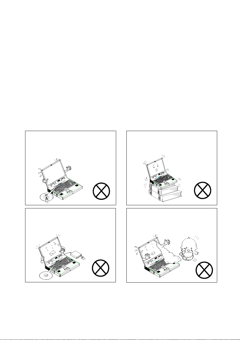
The following mentions the incorrect handling that is seriously inhibited. To
keep the computer from being damaged, please keep these precautions in
your mind.
Do not turn off the power in
operation.
Do not turn off the peripheral device
when the light is on.
Do not place the computer on
unstable surface.
Do not touch the poisonous liquid
when the LCD is broken.
Page 9
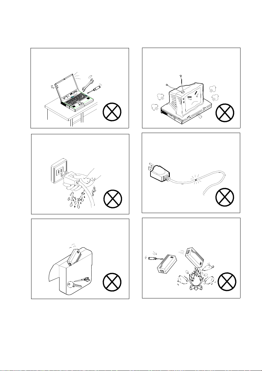
Do not disassemble the computer
Do not place anything heavy on the
yourself.
Do not touch power cord by wet hand. Do not use broken power cord.
Keep the computer away from any
metal appliance.
computer.
Do not throw the computer or
accessories into fire.
Page 10
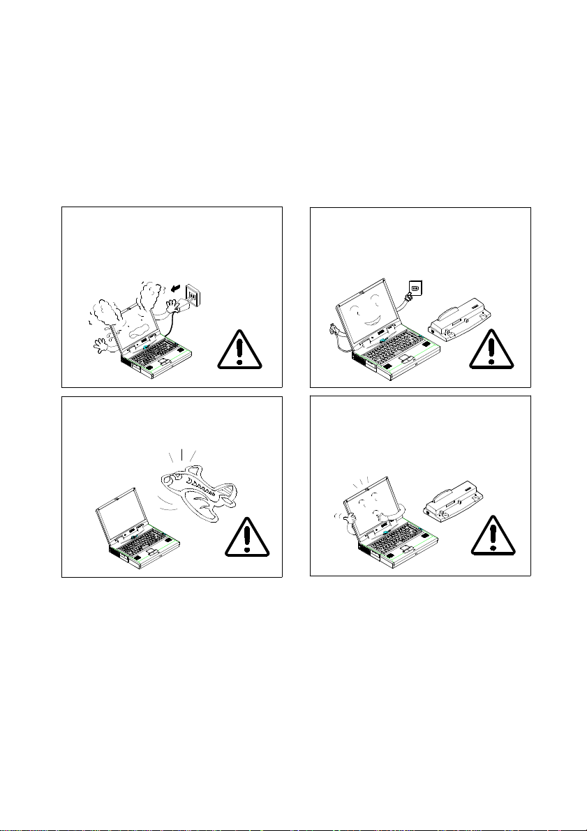
The following mentions the actions that are important for your computer. To
keep your computer in the most excellent condition, please follow the
instruction as much as possible.
If there is unusual odor, heat or
smoke, unplug the power cord
immediately.
Follow the use instruction in taking
airplane.
Unplug the power cord in attaching
peripheral device.
Use the same brand of peripheral
device.
Page 11
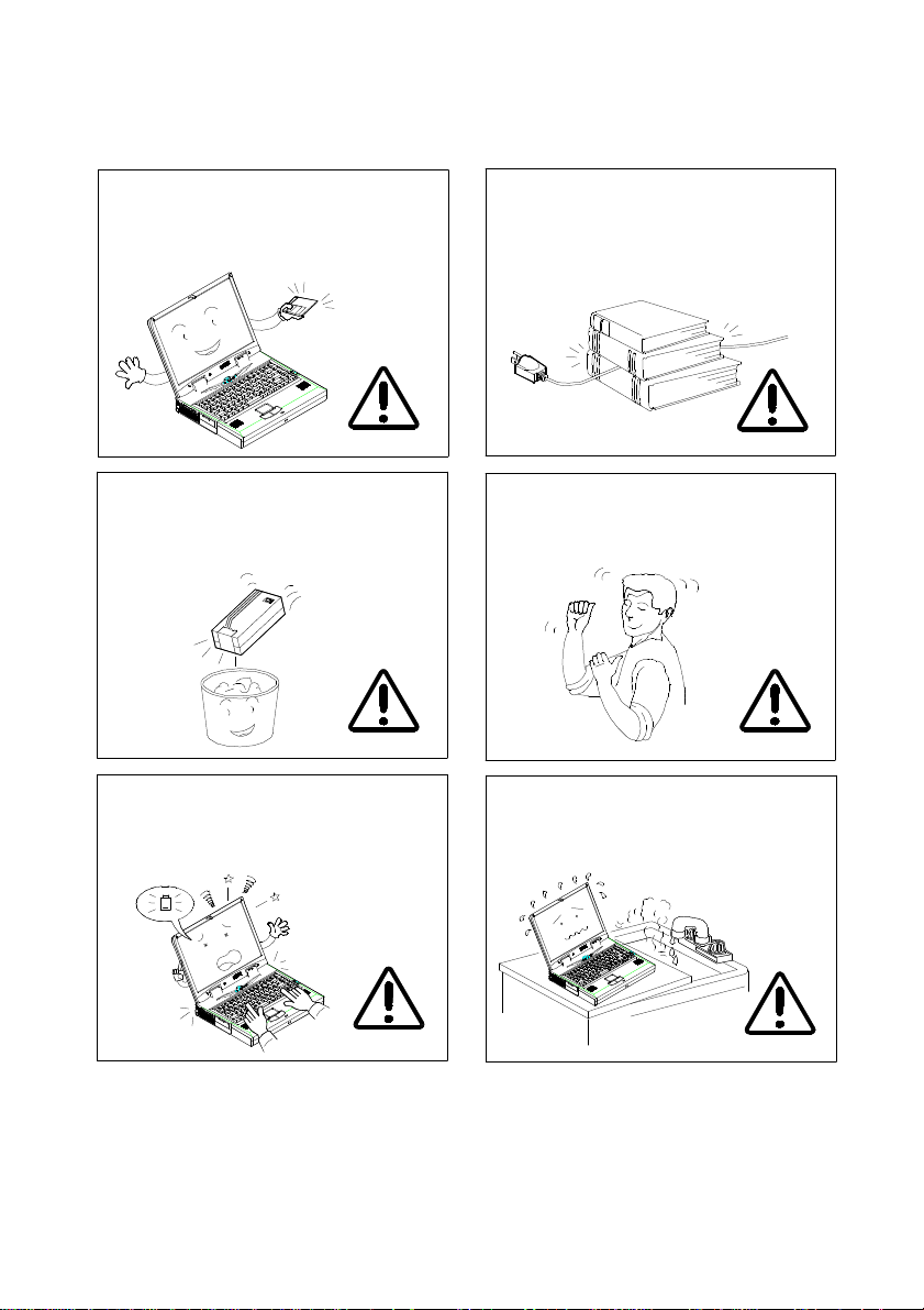
Maintain your computer regularly. Do not place heavy thing on the power
cord.
Affix tap to the contact plate while
putting the battery into keeping box.
The data is easy to lose in low power
status.
Take a rest after a long time of work.
Please keep the computer away from
humid environment.
Page 12

Conventions
This manual uses the following conventions to describe, identify, and
highlight terms and operating procedures.
Text Conventions
Text in boldface contains messages that are important for safe operation.
Please read.
Characters in boldface represent specific items or keys, e.g. CardBus, Fn
key.
File names are presented in bold capitals, e.g. A:\>0VMAKFIL ————Pn.
Abbreviations
For the purpose of clarity, abbreviations are enclosed in parentheses
following their definition; for example, Enhanced Parallel Port (EPP) mode.
Icons
Icons identify ports and jacks of the notebook computer. The system status
indicators are also identified with their relative icons.
Keys
Keys appear in boldface. A plus sign (+) between two keys indicates that
they should be pressed simultaneously.
Messages
Note: A note is an advice that helps you make best use of your
notebook computer. Please read.
Page 13
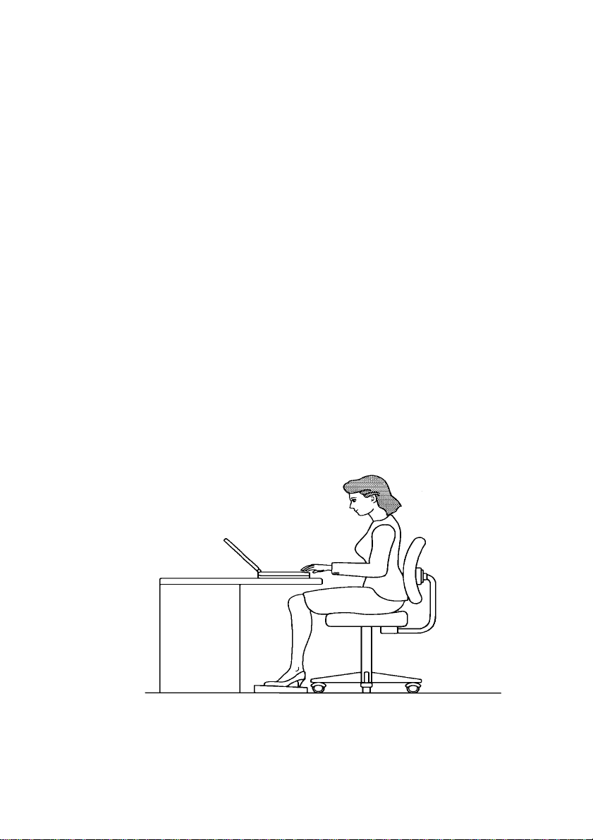
Ergonomics
Developing good work habits are important if you need to work in front of the
computer for long periods of time. Improper work habits can result in
discomfort or serious injury from repetitive strain to your hands, wrists or
other joints. The following are some tips to reduce the strain:
Adjust the chair and desk to make your elbow height near the height of
keyboard. Keep your forearms, wrists, and hands in a relaxed position.
Your knees should be slightly higher than your hips. Place your feet flat
on the floor or on a footrest if necessary.
Use a chair with a back and adjust it to support your lower back
comfortably.
Sit straight so that your knees, hips and elbows form approximately 90°
angles when you are working.
Page 14

Lighting
Proper lighting and comfortable display viewing angle can reduce the eye
strain and muscle fatigue in your neck and shoulders.
Position the display to avoid glare or reflections from overhead lighting
or outside light sources.
Keep the display screen clean and set the brightness and contrast to
levels that allow you to see the screen clearly.
Position the display directly in front of you at a comfortable viewing
distance.
Adjust the display viewing angle to find the best position.
In addition, continuous concentration on computing work can result in
discomfort and injury. Remember to:
Alter your posture frequently.
Stretch and exercise your body several times a day.
Take periodic breaks when you work at the computer for long periods of
time. Frequent and short breaks are of greater benefit than fewer and
longer breaks.
Page 15

Page 16

Page 17

Chapter 1 Getting Started
This chapter provides you with the introduction to the Notebook Computer. It
will familiarize you to the computer’s features, components, operating
environment and the power sources.
Unpacking the Notebook
Features of the Notebook
Operating environment
Powering the system
Chapter 1—Getting Started 1-1
Page 18
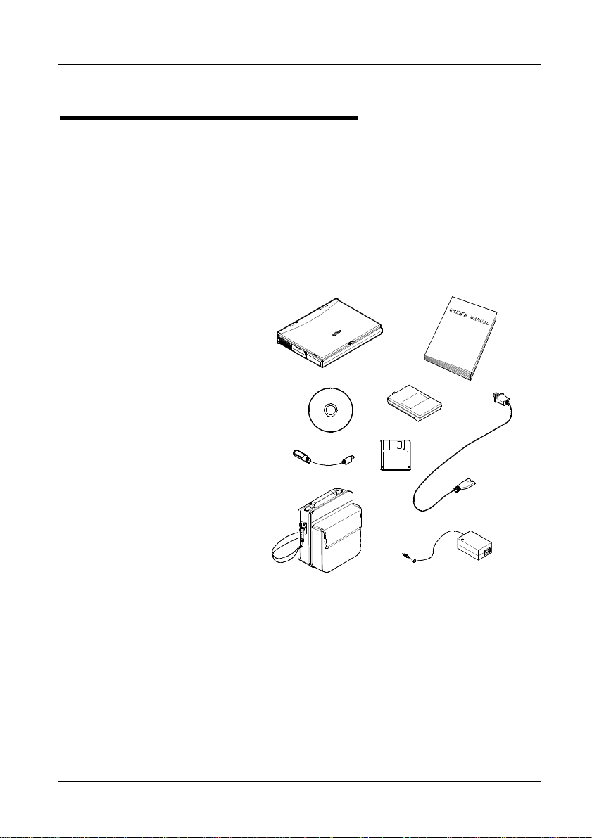
Unpacking the Notebook
Carefully unpack the Notebook Computer and the included accessories
(Figure 1-1). If there is any discrepancy or problem, contact your dealer
immediately. Be sure to save the packing materials in the event that the
notebook needs to be shipped in the future. The shipping carton should
contain the following items:
❍ Notebook computer
❍ CD for Drivers
❍ PS/2 Transfer Cable
❍ Carrying Bag
❍ User’s Manual
❍ Battery Pack
❍ Utilities Diskette
❍ Power Cord
❍ Power Adapter
1-2 User’s Manual
Figure 1-1
Page 19
Features of the Notebook
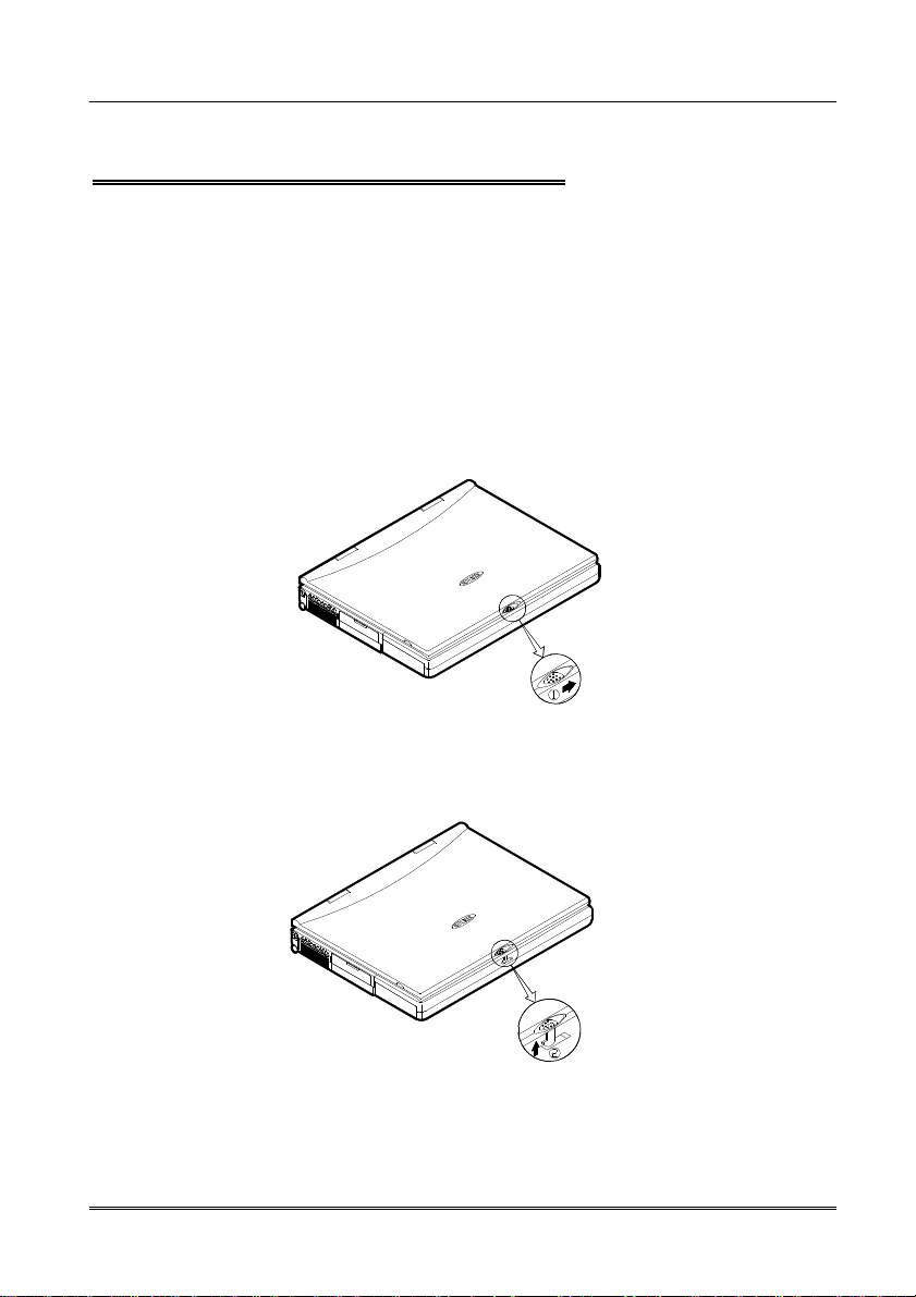
Opening the LCD Cover
1. Push the latch towards the right to open the top cover. (Figure 1-2)
2. Lift the top cover to reveal the LCD (Liquid Crystal Display) panel and
the keyboard.
3. Adjust the LCD panel to a comfortable viewing angle.
4. Press the power button to turn the system on or off (Figure 1-4).
Figure 1-2
Figure 1-3
Chapter 1—Getting Started 1-3
Page 20
System Status Indicators
Figure 1-4
Power button
Figure 1-5
Power button
Use this button to turn the system on or off (Figure 1-4). After proper
configuration under SCU (System Configuration Utilities), this button can
be used as suspend/resume hot button (refer to Chapter 3: BIOS Utilities,
Power Menu for more information).
Note: After turning off the system, wait for a few seconds to power it on
again.
1-4 User’s Manual
Page 21
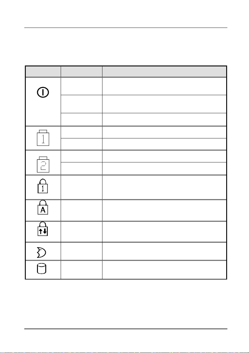
System Status LED Indicators
The LED indicators show the system’s operation status (see Figure 1-4 &
1-5).
Icon Color Description
Green Battery power is used with the system
turning on.
Red AC power is used with the system turning
on.
Blinking Red Battery power is critically low.
Green 1st Battery is fully charged.
Red 1st Battery is being charged.
Green 2nd Battery is fully charged.
Red 2nd Battery is being charged.
Green The embedded numeric keypad feature is
activated
Green The Caps Lock feature is activated.
Green The Scroll Lock feature is activated.
Green The system has entered the configured
suspend mode.
Green The hard disk is being accessed.
Chapter 1—Getting Started 1-5
Page 22
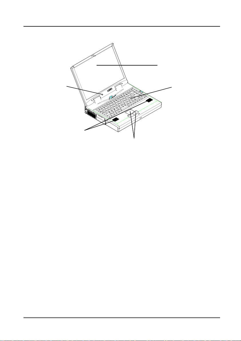
Top-Front View
➊
➎
➌
➍
Figure 1-6
➋
➊ LCD Panel
The Notebook is equipped with a LCD (Liquid Crystal Display) panel.
Depending upon the model you have purchased, the display screen can
be a 13.3” or 14.1” XGA TFT color panel. The notebook’s LCD panel
supports up to 1024×768×16M resolution. The LCD panel is driven by a
AGP bus video controller with 4MB video memory.
➋ Keyboard
The Notebook uses an 88-key keyboard in which the numeric keypad is
embedded. It supports Windows 95 by incorporating two Windows 95
special keys. The notebook keyboard design emulates a full-sized
desktop one and supports various language versions. Please refer to
chapter 2: Operation for more information on using keyboard.
1-6 User’s Manual
Page 23

➌ Stereo Speakers
Two built-in speakers provide clear stereo sound.
➍ Trackpad and Buttons
The pointing device features a sensitive glide pad for precise movements.
It is compatible with the IBM PS/2 mouse. The buttons of the trackpad
function as those of a standard mouse.
➎ Microphone
This is the built-in microphone for recording sound into your applications.
Chapter 1—Getting Started 1-7
Page 24
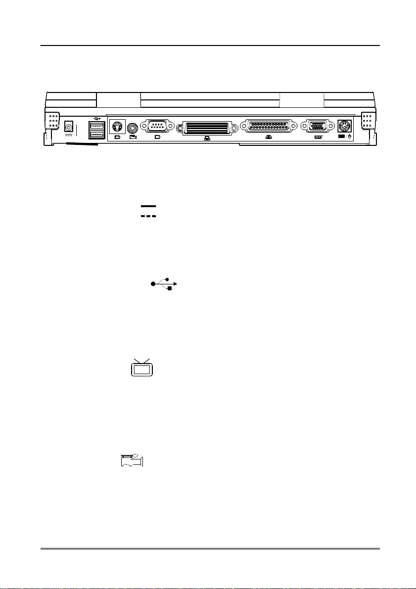
Rear View
➊ ➋ ➌ ➍ ➎ ➏ ➐ ➑ ➒
➊ AC-in Socket
Plug the AC adapter into this socket for power supply. Pull the plug (not
the cord) directly back to disconnect.
➋ Dual USB Ports
The dual Universal Serial Bus (USB) ports simplify the expansion
capability for peripheral devices. You can optionally connect the USB
Figure 1-7
devices such as a mouse, keyboard or monitor to the notebook.
➌ S-video Jack
Use this jack to transmit video signal to a TV set. You may need to
select the video standard (NTSC/PAL) for video display (please refer to
Chapter 3, Components Menu for more information).
➍➍➍➍ RCA Jack
This jack accepts analog composite signals from external video devices,
e.g. CCD Camera, Camcord.
1-8 User’s Manual
Page 25
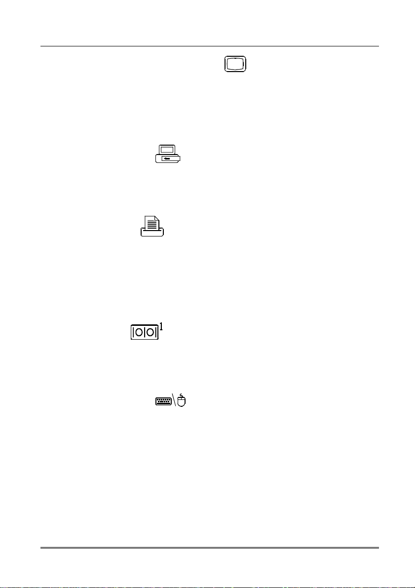
➎ External Monitor (CRT) Port
The External Monitor uses a 15-pin connector for connecting an external
CRT monitor. Simultaneous display in LCD screen and external CRT
monitor is available.
➏ Expansion Port
The Expansion port uses a 176-pin Docking connector for connecting a
Port Replicator.
➐ Parallel Port
The Parallel Port uses a 25-pin female connector for connecting a parallel
printer or other parallel devices. This parallel port supports EPP
(Enhanced Parallel Port) V1.7/V1.9 and ECP (Extended Capabilities Port)
modes.
➑ Serial Port
The RS-232C serial port uses a 9-pin male connector for connecting an
external serial mouse, serial printer or fax/modem.
➒ PS/2 Type Ports
The PS/2 Type Port uses 6-pin connector for connecting an external PS/2
type mouse or keyboard.
Chapter 1—Getting Started 1-9
Page 26
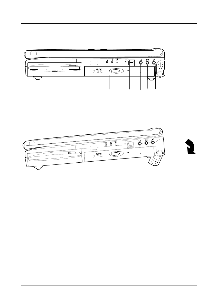
Right-side View
➊ ➋ ➌ ➍ ➎ ➏ ➐ ➑
Figure 1-8
Figure 1-9
➊ Removable 3.5” Floppy Disk Drive
The Notebook comes standard with a removable 3.5” 1.44MB floppy
drive installed in a bay. The floppy disk drive module can be replaced with
optional drive units, such as a 12.7mm high 2.5” hard disk drive, a
12.7mm high LS-120 120MB floppy drive or a secondary battery pack.
(Please refer to Chapter 2: Operation for more information on using
floppy disk drive.)
1-10 User’s Manual
Page 27

➋ Infrared
The notebook is equipped with an infrared feature that allows the
communication with an infrared-compatible device. The Infrared port
supports IrDA (HPSIR) 1.1 mode, Amplitude Shifted Keyed IR (ASKIR)
mode, and Fast IR (FIR) mode.
➌ Removable 5.25” CD-ROM Drive
The notebook comes standard with a 24-speed 5.25” CD-ROM drive. The
removable CD-ROM drive module can be replaced with the optional drive
units, such as a 12.7mm high DVD-ROM drive, or a third Hard Disk drive.
(Please refer to the Chapter 2: Operation for more information on using
the CD-ROM.)
➍ Phone Jack (option)
The phone jack is used to support the built-in modem. You can attach a
phone line to the jack and insert a modem card (optional) into the modem
socket on the mainboard.
➎ Speaker-out Jack
Headphone or speakers can be attached to the system through this jack.
➏ Line-in Jack
External audio source can be fed into the Notebook through this jack.
Chapter 1—Getting Started 1-11
Page 28

➐ Microphone-in Jack
Connect an external microphone to the system.
➑ Right-side Stand
Move this stand (together with the left one) to adjust the typing angle. If a
high speed CPU is installed on the system, erecting the stands on both
sides will be necessary for heat dissipation during operation. (Figure 1-9)
1-12 User’s Manual
Page 29
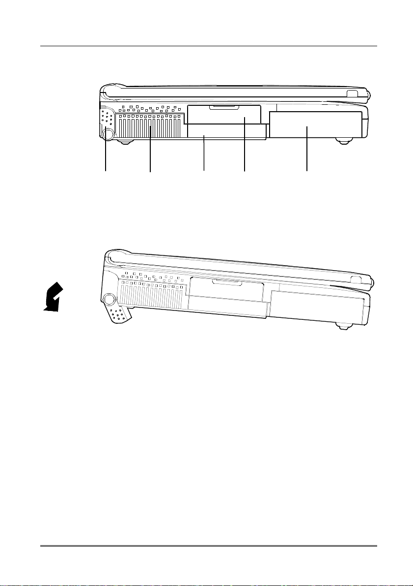
Left-side View
➊ ➋ ➌ ➍ ➎
Figure 1-10
Figure 1-11
➊ Left-side Stand
Move this stand (together with the right one) to adjust the typing angle.
If a high speed CPU is installed on the system, erecting the stands on
both sides will be necessary for heat dissipation during operation (Figure
1-11).
➋ Ventilation
The Notebook provides ventilation to dissipate the system’s operating
heat. Do not block or obstruct it during operation.
Chapter 1—Getting Started 1-13
Page 30

➌ Removable 2.5” Hard Disk Drive Module
The notebook comes standard with a removable 2.5-inch IDE Hard Disk
Drive with a height of 12.7mm installed in a bay. (Please refer to Chapter
2: Operation for more information on using Hard Disk Drive.)
➍ PC Card Sockets
The notebook provides two Type II or one Type III PC card socket. Both
sockets will expand the system capabilities when a PC card is inserted.
(Please refer to Chapter 2: Operation for more information on Using PC
Card socket.)
➎ Battery Pack
The notebook comes with a rechargeable battery pack that lets you
operate the computer without an external power source.
1-14 User’s Manual
Page 31

Bottom View
➊
➋
➎
➍
Figure 1-12
➌
➊ CD-ROM latch
Push this latch to release the CD-ROM module from its bay. (Please refer
to Chapter 2: Operation for more information on inserting or removing the
CD-ROM.)
➋ Hard Disk Drive latch
Push this latch to release the Hard Disk Drive module from its bay.
(Please refer to Chapter 2: Operation for more information on Inserting or
removing the Hard Disk Drive.)
Chapter 1—Getting Started 1-15
Page 32

➌➌➌➌ CPU Cover
Detaching the screws to remove the cover. The CPU is under the heat
sink and the cover. You may upgrade the CPU for higher performance.
➍➍➍➍ Battery Pack latch
Push this latch to release the Battery Pack from its bay. (Please refer to
Chapter 1: Getting Started for more information on Inserting or removing
the Battery Pack.)
➎➎➎➎ Floppy Disk Drive latch
Push this latch to release the Floppy Disk Drive module from its bay.
(Please refer to the Chapter 2: Operation for more information on
inserting or removing the Floppy Disk Drive.)
1-16 User’s Manual
Page 33

Operating Environment
Proper care and operation of your notebook computer will prolong the use
period. Make sure the computer is not:
❍ Exposed to excessively heat or direct sunlight.
❍ Subjected to shock or vibration.
❍ Exposed to strong magnetic fields.
❍ Left in a place where foreign matter or moisture may enter the
system.
Figure 1-13
Chapter 1—Getting Started 1-17
Page 34

Powering the System
You can use the AC power adapter or battery pack to power the computer
system.
AC Power Adapter
Use only the power adapter that comes with your Notebook Computer.
Using the incorrect power adapter will cause damage to the Notebook and
its components.
1. Plug the power adapter to the AC-in socket on the rear panel of the
Notebook.
2. Connect the power cord to the power adapter.
3. Plug the AC power cord into a properly grounded outlet.
4. Refer to Chapter 1, System Status Indication for more information on
system power status.
1-18 User’s Manual
Figure 1-14
Page 35

Battery Pack
Power for continuous portable operation of the Notebook is provided by a
battery pack. When the battery pack is fully charged, you can operate the
computer for approximately two hours. However, the actual operating time
will be determined by the application used and the configuration set.
Removing
1. Turn the Notebook over.
2. Locate the Battery Pack latch. (Figure 1-15)
3. Push the latch in the direction as indicated and draw the battery pack
out the bay.
Inserting
1. Turn the Notebook over.
2. Insert the battery pack into the bay.
3. Make sure the battery slides into the bay properly and mates with it
connector firmly.
Figure 1-15
Chapter 1—Getting Started 1-19
Page 36

Recharging by AC Power
The system’s battery pack will recharge whenever the system is plugged into
the AC power supply, regardless of whether the system is being operated or
not.
1. You may connect the AC power adapter to the Notebook Computer at
any time to begin recharging the system’s battery pack. You do not
need to turn off the system’s power.
2. It will take several hours to recharge the battery to its full charge status.
3. Please refer to Chapter 1, System Status Indicators for more
information on battery charge status.
Proper Handling of the Battery Pack
❍ Do not attempt to disassemble the battery pack under any
circumstances.
❍ The battery may explode if exposed to fire or high temperatures.
❍ Avoid short circuiting the battery by preventing contact between the
metal terminals (+, -)
1-20 User’s Manual
Page 37

Chapter 2 Operation
The Notebook has many advanced features to help you with your computing
work. This chapter describes each of the Notebook’s hardware features and
shows you how to use them.
Before you begin working with any internal components of the
Notebook, remove the battery and disconnect the AC power adapter.
Make sure that you wear an anti-static wrist strap to ground yourself
before working with any internal components of the Notebook. Static
electricity may damage the components.
Upgrading Processor
Setting DIP Switch
Using Hard Disk Drive
Using Floppy Disk Drive
Using CD-ROM
Using PC Card Sockets
Using Hot Keys
Using Numeric Keypad
Using Power Management
Attaching Peripheral Devices
Chapter2—Operation 2-1
Page 38

Upgrading the Processor
The notebook supports Intel Celeron processor at 300MHz, 333MHz,
366MHz, 400MHz and 433MHz Core frequencies. The Intel Celeron
processor provides good performance for applications running on advanced
operating systems such as Window 95/98, Window NT, and UNIX. In
addition, It features a Dynamic Execution microarchitecture and also
executes MMX technology instructions for enhanced media and
communication.
Because of using the cost-effective packaging technology, user can easily
install the processor by plugging the PPGA package into the 370-pin socket
(PGA 370). However, it is recommended to upgrade the system by the
certified technicians.
2-2 User’s Manual
Page 39

Replacing the Processor
1. Remove all the power sources (AC power and battery).
2. Turn the Notebook over.
3. Remove the CPU cover.
4. Remove the screws that fasten the heat sink mounted on the
Processor.
5. Carefully detach the Processor from the mainboard.
Note:
Wait for the CPU to cool down before replace it.
Contact your dealer for the proprietary tool to replace the CPU.
CPU Cover
Heat Sink
Processor
Socket 370
Figure 2-1
Reinstalling the Processor
To insert or extract your processor, please contact your service dealer for
Chapter2—Operation 2-3
Page 40

correct operation.
2-4 User’s Manual
Page 41

Reinstalling the Heat Sink
Make sure that the heat sink cable is properly placed (Figure 2-3).
Figure 2-2
Figure 2-3
Chapter2—Operation 2-5
Page 42

DIP Switch (SW1)
Purpose
S1-1 S1-2 S1-3 S1-4 S1-5 S1-6 S1-7 S1-8
Setting the DIP Switch
Updating the Flash ROM BIOS
In order to keep up with the latest system BIOS, your notebook may be
upgraded. Consult your dealer for further information. The DIP Switch needs
to be set in the On position when updating the existing system BIOS. The
DIP Switch should be reset to the Off position after BIOS updating is
complete.
Flash ROM BIOS
OFF OFF X X X X X X Existing BIOS
ON ON X X X X X X Update BIOS
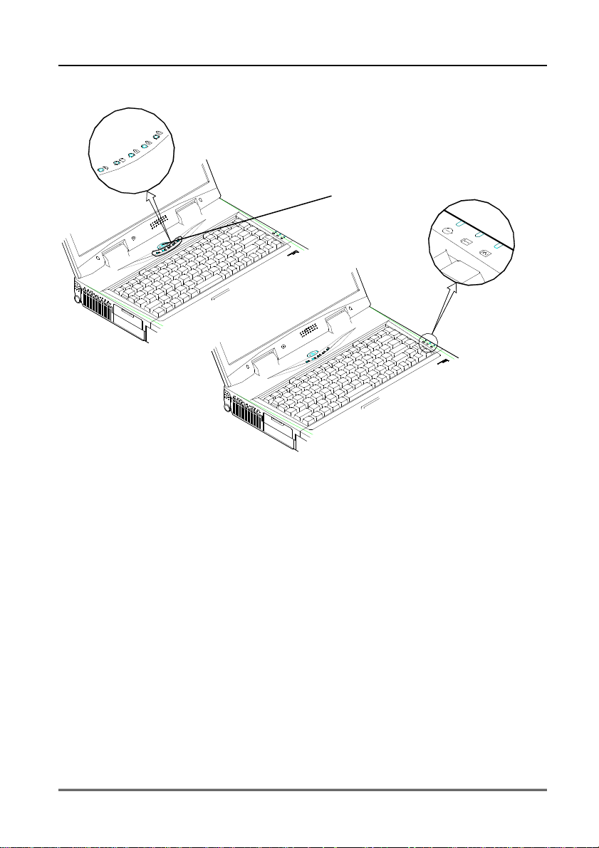
Accessing the 8-Pole DIP Switch (SW1)
Access the 8-Pole DIP Switch to set the BIOS.
1. Turn the system power off.
2. Press the two keyboard latches and Carefully lift the keyboard assembly
out to expose the mainboard. Adjust the DIP Switch SW1 to set the
configuration.
2-6 User’s Manual
Figure 2-4
Figure 2-5
Page 43

Expanding Memory
Bank 0
Bank 1
Minimum
The system has two memory sockets for different RAM modules to expand
the memory up to 256MB. These RAM modules are of a 144-pin SODIMM
(Small Outline Dual In-line Memory Module) type. The Notebook supports
EDO, and SDRAM operation. The total memory size is automatically
detected by the POST routines. With the following different RAM
combinations (for reference), the total memory size can be:
(64-bit)
16MB 0MB
0MB 16MB 16MB
16MB 8MB 24MB
8MB 16MB 24MB
16MB 16MB 32MB
32MB 0MB 32MB
0MB 32MB 32MB
32MB 8MB 40MB
8MB 32MB 40MB
32MB 16MB 48MB
16MB 32MB 48MB
64MB 0MB 64MB
0MB 64MB 64MB
64MB 8MB 72MB
8MB 64MB 72MB
64MB 32MB 96MB
32MB 64MB 96MB
64MB 64MB 128MB
0MB 128MB 128MB
128MB 32MB 160MB
32MB 128MB 160MB
128MB 64MB 192MB
64MB 128MB 192MB
128MB 128MB 256MB
(64-bit)
Power
3.3V
Speed
EDO: 60ns
SDRAM:75
MHz
Total Size
16MB
Note: You can not use the EDO RAM and SDRAM together.
Chapter2—Operation 2-7
Page 44

are the non
-
component areas.)
67.6mm
Accessing the Memory Sockets
1. Turn the system power off.
2. Press the two keyboard latches to elevate the keyboard from its normal
position.
3. Carefully lift the keyboard assembly out to expose the mainboard.
Locate the memory sockets (Figure 2-7).
Note:
The memory socket Bank 1 is a reverse type, make sure you install
the memory module with the reverse side to fit its connector.
Please ensure that each edge of the memory module (SDRAM) has
no component mounted on (see Figure 2-6). It is recommended to
use the RAM module that complies with Intel unbuffered SO-DIMM
(67.6mmX31.75mm). Please consult your dealer for detailed
information.
Non-component area
(The edges of the memory module
2-8 User’s Manual
31.75mm
Bank 0
Bank 1
Figure 2-7
Figure 2-6
Page 45

Installing the Memory Module
Follow the steps below to install the memory module:
1. Turn the system power off.
2. Press the two keyboard latches to elevate the keyboard from its normal
position.
3. Carefully lift the keyboard assembly out to expose the mainboard.
Locate the memory sockets (Figure 2-7).
4. Position the memory module at a slight angle (45∘∘∘∘) and fit its
connectors into the socket firmly (Step 1 of Figure 2-8).
5. Press two edges of the memory module (Step 2 of Figure 2-8) to
make it locked into place.
6. Reinstall the keyboard assembly.
Note:
It is recommended to install the memory module in the order of Bank 0,
Bank 1 (see Figure 2-9). Please refer to the table of DRAM
combinations or consult your dealer for a proper installation.
Figure 2-8
Chapter2—Operation 2-9
Page 46

Removing the Memory Module
1. Turn the system power off.
2. Press the two keyboard latches to elevate the keyboard from its normal
position.
3. Carefully lift the keyboard assembly out to expose the mainboard.
Locate the memory sockets (Figure 2-7).
4. Gently pull the two latches on both ends of the module outward (Step 1
of Figure 2-9). The module will pop up (Step 2 & 3 of Figure 2-9).
5. Remove the memory module.
6. Reinstall the keyboard assembly.
2-10 User’s Manual
Figure 2-9
Page 47

Using the Hard Disk Drive
The notebook is equipped with a 2.5” IDE hard disk drive mounted in a
removable case. Therefore, the hard disk drive can also be easily removed
and replaced with another hard disk drive with a height of 17mm. The hard
disk drive supports Programmed I/O (PIO) mode 4, Master mode and Ultra
ATA (Ultra DMA-33) mode which can provide a high performance data
transfer rate at speeds up to 33 MB/second.
Removing the Hard Disk Drive Module
1. Turn off the power.
2. Turn the Notebook over.
3. Locate the Hard Disk drive latch (Figure 2-10).
4. Push the latch in the direction as indicated and pull the hard disk drive
module out of the bay.
Figure 2-10
Chapter2—Operation 2-11
Page 48

Replacing the Hard Disk Drive
1. Remove the two screws on each side of the case. (Figure 2-11)
2. Gently disconnect the cable from the hard disk drive.
3. Connect the replacement hard disk drive with the cable.
4. Insert the replacement hard disk drive into the case.
5. Fasten the screws of each side.
Note: The hard disk drive with different height must use the different
case to house itself. Contact your dealer for details about these
replacements.
Figure 2-11
Inserting the Hard Disk Drive Module
1. Insert the hard disk drive module into the bay
2. Make sure it slides into the bay properly and mates with the connector
firmly.
2-12 User’s Manual
Page 49

Using Floppy Disk Drive
The Notebook is equipped with a removable 1.44MB, 3.5” floppy disk drive
module. It is usually designated as drive A by default and may be used as a
boot device if properly set in SCU (please refer to Chapter 3, BIOS Utilities).
You may replace the floppy disk drive module with the following options: a
2.5” secondary IDE hard disk drive (of 12.7mm high), a 120MB LS-120
floppy disk drive (of 12.7mm high), or a secondary battery pack. Contact
your dealer for detailed information about these options.
Inserting/Removing the Diskette
Always insert your floppy diskette with label-side up when using the floppy
drive. Press the eject button on the top-right corner of the floppy drive to
remove your diskette.
Figure 2-12
Chapter2—Operation 2-13
Page 50

Replacing the Floppy Disk Drive
1. Turn off the power.
2. Turn the Notebook over.
3. Locate the Floppy Disk Drive latch (Figure 2-13).
4. Push the latch in the direction as indicated and pull the floppy disk drive
module out of its bay.
5. Insert the replacement module into the bay.
6. Make sure it slides into the bay properly and mates firmly with the
connector.
2-14 User’s Manual
Figure 2-13
Page 51

Write-Protecting Diskettes
Diskettes can be write-protected to prevent files from being accidentally
erased or destroyed by system. To write-protect a 3.5” floppy diskette, move
the built-in write-protect tab to the write-protect position, (“up” so that you
can see through the “hole” in the upper, right-hand corner of the diskette).
Putting the write protect tab back “down’ will enable you to write data on the
disk again.
Do’s and Don’ts
❍ Always make backup copies of your software and data diskettes.
❍ Keep the diskettes away from the magnetic fields.
❍ Do not remove the diskettes from the drive while the diskette “in-use”
light is on.
❍ Do not open or remove the protective shutter that covers the
diskette’s media.
❍ Do not allow dust or moisture on the diskettes.
❍ Do not bend or throw the diskettes.
❍ Do not clean the diskettes with liquids or solvents.
Chapter2—Operation 2-15
Page 52

Using the CD-ROM
The Notebook is equipped with a removable CD-ROM drive module. It is
usually designated as drive D by default and may be used as a boot device if
properly set in SCU (please refer to Chapter 3, BIOS Utilities). You may
replace the CD-ROM drive module with the following options, DVD-ROM
drive (of 12.7mm), or the third battery pack.
To insert a CD, press the Eject Button and place the CD on the Disc Tray
with label-side up. The Busy Indicator will light up while the data is being
accessed or while playing an audio CD. When the power of the system is
unexpectedly interrupted, insert an instrument such as a straightened paper
clip into the Emergency Eject Hole to manually eject the tray.
2-16 User’s Manual
Disc Tray
Emergency Eject Hole
Busy Indicator
Eject Button
Figure 2-14
Page 53

Removing the CD-ROM Module
1. Turn off the power.
2. Turn the Notebook over.
3. Locate the CD-ROM latch (Figure 2-15).
4. Push the latch in the direction as indicated and pull the CD-ROM
module out of the bay.
Note: Do not disassemble the CD-ROM module by yourself. Only
certified technicians should perform repairs to the CD-ROM module.
Figure 2-15
Chapter2—Operation 2-17
Page 54

Loading the Compact Discs
1. Turn on the power.
2. Press the CD-ROM eject button; the disc tray will pop out partially.
3. Gently pull the disc tray out.
4. Carefully load the CD on the disc tray with label-side up. Make sure the
CD is seated properly.
5. Push the tray into the computer to close it.
2-18 User’s Manual
Figure 2-16
Page 55

Handling of the Compact Discs
Proper handling of your CDs will prevent them from being damaged and
ensure the accessibility of the data stored on them.
❍ Hold the CD by the edges; avoid touching the surface of the disc.
❍ Use the clean, soft, dry cloth to remove the dust or fingerprints.
❍ Do not use a pen to write on the surface.
❍ Do not attach any paper or other materials to the surface of the disk.
❍ Do not store or place the CD in the areas where it will be exposed to
high temperatures.
❍ Do not use the benzene, thinners, or other cleaners to clean the CD.
❍ Do not bend the Compact Disc.
❍ Do not drop or subject the CDs to shock.
Chapter2—Operation 2-19
Page 56

Using the PC Card Sockets
The PC cards can expand the capabilities of the notebook computer. Your
Notebook is equipped with two PC card sockets that accommodate one Type
III card or two Type II cards. These sockets support both PCMCIA standard
release 2.0 cards and 32-bits Cardbus (PC card 95) cards, and so on. PC
cards can be LAN, fax/modem, communication devices, or expanded
memory ones. These PC card sockets can accept either 3.3V or 5V PC
cards.
The lower socket named socket A is capable of ZV (Zoomed Video), which
allows a direct connection between a PC card and video devices that
enables high quality video playback (Figure 2-19).
Inserting the PC Cards
1. Open the access door of the PC card sockets (Figure 2-17).
2. Align the PC card with the appropriate socket and push it in firmly until it
locks into place.
Figure 2-17 Figure 2-28
2-20 User’s Manual
Page 57

Removing the PC Cards
Two eject buttons are located next to each socket. Press the appropriate
eject button to remove the PC card from its socket. (Please refer to Figure
2-19)
Eject button
for Socket B Socket B
Eject button
for Socket A
Figure 2-19
Socket A
Chapter2—Operation 2-21
Page 58

Using the Hot Keys
Located on the bottom-left corner of the keyboard layout is a colored Fn key
(Figure 2-20). It is a special feature designed only on the Notebook for an
easy access to system features. Simultaneously press Fn key and one of the
following keys to execute the specific functions:
Hot Key System Features
Fn+F3
Fn+F3
Fn+F3Fn+F3
Fn+F6
Fn+F6
Fn+F6Fn+F6
Fn+F9
Fn+F9
Fn+F9Fn+F9
Fn+F10
Fn+F10
Fn+F10Fn+F10
Fn+F11
Fn+F11
Fn+F11Fn+F11
Fn+F12
Fn+F12
Fn+F12Fn+F12
Fn+Z
Fn+Z
Fn+ZFn+Z
Fn+Esc
Fn+Esc
Fn+EscFn+Esc
Expand the display of LCD
Toggle CRT/LCD/LCD+CRT/TV/CRT+TV
Decrease the brightness of LCD
Increase the brightness of LCD
Decrease the audio volume
Increase the audio volume
Toggle audio mute on/off
Suspend/resume
2-22 User’s Manual
Page 59

Figure 2-20
Chapter2—Operation 2-23
Page 60

Using the Numeric Keypad
The Notebook features an 88-key keyboard with an embedded numeric
keypad for numeric data input (Figure 2-21). The colored keys in the middle
section of the keyboard will function as a Numeric Keypad. The numeric
keypad is engaged when the NumLock LED indicator shines green light.
Follow these steps to access the Numeric Keypad:
❍ Press the NumLock Key to activate the Numeric Keypad.
❍ Press the Fn key and any colored key together to activate the
Numeric Keypad.
2-24 User’s Manual
Figure 2-21
Page 61

Using the Power Management
The Notebook provides you with some built-in power management features
to reduce the power consumption without affecting the performance of the
system in most application.
Advanced Power Management (APM 1.2)
The Notebook provides built-in Advanced Power Management (APM 1.2)
supporting to reduce power consumption. Some operating systems do not
support APM, such as Windows NT, and therefore, cannot take
advantage of the system’s capabilities in this OS environment.
Chapter2—Operation 2-25
Page 62

Hard Disk Standby
The system will turn off the Notebook’s hard disk drive after a specified
period of inactivity. The Hard disk drive will be turned back on once the
system attempts to read data from it or write data to it. You can adjust the
Standby timeout period in the power menu of BIOS utilities
Global Standby
In Global Standby mode, the CPU clock will be stopped and most of the
controllable peripheral devices will be powered off. If the idle timer expires
before any system activity is detected, the system will change from Standby
mode into Suspend mode.
Suspend and Resume
Under the circumstance of extremely low power, the system will stop all
tasks stored them in memory to save the power. This is called Suspend
mode. The Suspend Mode features three levels: Powered-On-Suspend
(POS) mode, Suspend-To-RAM (STR) mode and Suspend-To-Disk (STD)
mode.
Note: Be sure not to initiate the Suspend Mode when any of the disk
drives is accessed such as HDD, FDD and CD-ROM drive.
The system operation can be returned to exactly where it was suspended
when the wake-up event occurs. This is called Resume.
2-26 User’s Manual
Page 63

Powered On Suspend (POS)
In these two suspend modes, Powered-On-Suspend (POS) saves the less
amount of power than STD (Suspend to Disk) mode. However, it takes the
least time to return to full operation.
Resume from POS Mode
The system may be resumed from the Powered-On-Suspend mode by:
❍ Alarm resume (month/day/hour/minute): The system will resume at
the specified time.
❍ Modem ring: The system will resume when a modem ring is detected.
(COM port only)
❍ Any keyboard key pressed
❍ Depressing the power button (if configured as Suspend/Resume
function under SCU)
Chapter2—Operation 2-27
Page 64

Suspend To Disk (STD)
Suspend to Disk is a 0-volt suspend mode for system power management.
STD mode saves more amount of power than POS mode but takes longer
time to return to full operation.
1. Use your operating system’s FDISK program to delete all partitions of
the hard disk if any already exist on the target drive.
2. Boot the system from the drive A: and run the 0VMAKFIL.EXE Utility to
create the Suspend to Disk partition on the hard disk. The size of the
Suspend to Disk will accommodate the installed DRAM (n) plus 4MB
integrated video RAM.
A:\>0VMAKFIL ————Pn
For example, if the system DRAM is 32MB, 0VMAKFIL will create a partition
size of approximately 36MB.
A:\>0VMAKFIL ————P32
Note: Rewrite the sector signatures if you need to partition the hard
disk again.
C:\>0VMAKFIL ————PW
3. Use your FDISK program operating system to Re-partition the hard
disk.
Resume from the STD Mode
The system may be resumed from Suspend-To-Disk mode by:
❍ Power back on
❍ Alarm resume (month/day/hour/minute): The system will resume at
the specified time.
2-28 User’s Manual
Page 65

Attaching the Peripheral Devices
You can add a variety of external devices to your computer to expand your
computing capabilities.
Attaching a Phone Line (option)
The notebook is equipped with a phone jack for connecting a phone line. To
enable the function of a built-in modem, the users have to insert a modem
card (Optional) into the socket on the mainboard and attach a phone cord to
the jack.
Figure 2-22
Chapter2—Operation 2-29
Page 66

Attaching a PS/2 Keyboard or Mouse
The Notebook can be operated with an external PS/2 keyboard or mouse.
Make sure the mouse or keyboard has a cable with 6-pin connector for the
PS/2 port. If not, use the transfer cable that comes with your notebook.
2-30 User’s Manual
Figure 2-23
Page 67

Attaching a Serial Mouse
The serial port features a 9-pin connector. You can connect any serial device
such as a mouse to this port.
To connect a serial mouse, follow these steps:
1. Turn the system power off.
2. Connect the cable to the serial port on the rear panel of the Notebook
Computer.
3. Tighten the screws to fasten the cable to the serial port.
4. Turn on the Notebook Computer.
In addition, you may need to install the manufacturer-supplied driver for the
serial mouse. Refer to the device’s user’s guide for more information.
Figure 2-24
Chapter2—Operation 2-31
Page 68

Attaching a Parallel Printer
You may connect any standard Centronics-compatible parallel printer to your
Notebook through the parallel port.
To connect a printer, follow these steps:
1. Turn the system power off.
2. Connect the cable to the parallel port on the rear of the Notebook
Computer.
3. Tighten the screws to fasten the cable to the parallel port (Figure 2-25).
4. Insert the other end of the cable to the printer’s connector. Fasten the
cable’s connector.
5. Turn on the printer and Notebook Computer.
In addition, you will need to install the manufacturer-supplied driver for the
printer. Refer to the device’s user’s guide for more information. If the
connected printer supports EPP (Enhanced Parallel Port) or ECP (Extended
Capabilities Port) mode, please enter System Configuration Utility (SCU) to
configure the required setting.
Figure 2-25
2-32 User’s Manual
Page 69

Attaching an External Monitor (CRT)
The computer is capable of displaying not only on the internal LCD, but also
on an external XGA display monitor. Simultaneous display on LCD and
External monitor is available. You may enter the System Configuration Utility
(SCU) to select the appropriate parameters or use the Fn + F6 keys (refer to
Chapter 2, Using Hot Keys) to change the display setting.
To connect an External Monitor, follow these steps:
1. Turn the system power off.
2. Connect the cable to the CRT port on the rear panel of the Notebook
Computer.
3. Tighten the screws to fasten the cable to the CRT port.
4. Insert the other end of the cable to the external monitor.
5. Turn on the Notebook Computer.
Figure 2-26
Chapter2—Operation 2-33
Page 70

Attaching a Proprietary Port Replicator
The proprietary Port Replicator provides interfaces for those found on the
Notebook system. It can free you from fumbling with multiple cables every
time you leave the office. Please contact your dealer for detailed information.
2-34 User’s Manual
Figure 2-27
Page 71

Attaching a Video Input Device
The RCA jack on the rear panel of the Notebook allows analog composite
signal input from external video devices. You can connect a CCD to the RCA
jack.
Figure 2-28
Chapter2—Operation 2-35
Page 72

Attaching a TV Set
The S-video jack on the rear panel of the Notebook is used for transmitting
video signals to a TV set. You may select the video standard for video
display. Enter the System Configuration Utility (SCU), Components Menu to
specify the appropriate TV mode. Simultaneous display on external monitor
(CRT) and TV is available. You may enter the SCU to select the appropriate
parameters or use the Fn + F6 keys (refer to Chapter 2, Using Hot Keys) to
change the setting.
See figure 2-31 for information on attaching a TV set.
Note: Different countries use different TV broadcast standards. A TV
set must comply with the appropriate standard to properly receive the
broadcast signals. You should refer to your TV user guide to make sure
which TV standard you are using.
2-36 User’s Manual
Figure 2-29
Page 73

Attaching a USB-compatible Device
The Notebook provides a USB port for connecting an USB-compatible
keyboard, mouse or other devices. See Figure 2-30 for information on
connecting a serial mouse.
Figure 2-30
Chapter2—Operation 2-37
Page 74

Page 75

Chapter 3 BIOS Utilities
This chapter provides information regarding the Power On Self Test (POST)
and shows you how to use the System Configuration Utility (SCU) to
configure the system parameters. The settings made in BIOS SCU will affect
the performance of the notebook.
Power On Self Test (POST)
System Configuration Utility (SCU)
Chapter 3—BIOS Utilities 3-1
Page 76

Power On Self Test (POST)
The system BIOS (Basic Input/Output System) performs a series of Power
On Self Test (POST) on system memory and key computer components
when the computer is turned on every time. If an error exists, the POST
routine may halt execution (depending on the seriousness of the problem).
The POST also initializes BIOS configuration then boots the operating
system.
POST Message: Normal Operation
You will see the following message if no error exists after the POST is
performed
Note: You may press the Spacebar key to skip the memory test.
SystemSoft BIOS MobilePRO BIOS Version 1.01 (2482-00)-(R1.00.tr10)
Copyright 1983-1996 SystemSoft Corp. All Rights Reserved
333 MHz Celeron with MMX CPU
L2 Cache: 128K installed
4 MB Video RAM
SystemSoft Plug-n-Play BIOS Ver 1.17.01
Base Memory 000640 Kb
Extended Memory 007168 Kb
Total Memory 008192 Kb
Auto Detecting IDE Devices [Done]
<CTRL-ALT-S> to enter System Configuration Utility
3-2 User’s Manual
Page 77

POST Message: Error Detected
If an error is detected, a WARNING message will be displayed. You should
either press F1 key to continue, or press the Ctrl-Alt-S keys simultaneously
to enter the System Configuration Utility.
SystemSoft BIOS MobilePRO BIOS Version 1.01 (2482-00)-(R1.00.tr10)
Copyright 1983-1996 SystemSoft Corp. All Rights Reserved
333 MHz Celeron with MMX CPU
L2 Cache: 128K installed
4 MB Video RAM
SystemSoft Plug-n-Play BIOS Ver 1.17.01
Base Memory 000640 Kb
Extended Memory 007168 Kb
Total Memory 008192 Kb
WARNING – HARD DISK CONTROLLER 1 FAILURE
Auto Detecting IDE Devices [Done]
<CTRL-ALT-S> to enter System Configuration Utility
Press F1 to Continue
Chapter 3—BIOS Utilities 3-3
Page 78

Menu Bar Items
Pull
-
down Menu Items
System Configuration Utility
The System Configuration Utility (SCU) is a ROM-based configuration utility
that displays the system’s configuration status and provides users with a tool
to set their system parameters. The settings are stored in battery-backed
CMOS RAM which saves the information even when the power is turned off,
and retains it when the system is turned back on.
Information in the System Configuration Utility
The following shows the main menu and its submenu that may be changed
within the System Configuration Utility.
Startup Date and Time, Fast Boot, Boot Device, Display,
Enable Battery Low Beep, Enable LCD expand
Mode, Enable Power On Beep, Boot Password, SCU
Password.
Memory Cache Systems.
Disks Diskette Drives, IDE Settings, Enable LS120/ZIP100
Drive.
Components COM Ports, LPT Port, PS/2 Mouse Port, Microsoft
IntelliMouse Support, Keyboard Numlock, Keyboard
Repeat, TV Mode, Video In Enabled, ZV Port
Enabled.
Power Enable Power Saving, Low Power Saving, Medium
Power Saving, High Power Saving, Customize,
Suspend Controls, Resume Timer, Enable MODEM
Ring Resume, Enable Battery Low Suspend,
Advance CPU Controls.
Exit Save and Exit, Exit (No Save), Default Settings,
Restore Settings, Version Info.
3-4 User’s Manual
Page 79

Initiating the System Configuration Utility
The System Configuration Utility (SCU) will be accessed when pressing the
Ctrl, Alt, and S keys simultaneously.
<CTRL-ALT-S> to enter System Configuration Utility
The above message only lasts seconds. If you miss it, the computer will
initiate the boot process. You must reboot the system and try again within
the time limit if you want to enter the System Configuration Utility.
Figure 3-1
System Configuration Utility (SCU)
Chapter 3—BIOS Utilities 3-5
Page 80

Working with the Menu Bar (Main Menu)
After entering the SCU, you may use the following keys to work with the
menu bar (main menu).
Action Keys Used Description
Activate menus Alt Activate the System
Configuration Utility.
Select menu bar item
Accept menu item Mouse left button
Cancel current action Mouse right button
Left arrow (←)
Right arrow (→)
The highlighted
letter key
Spacebar
Enter
Esc
Move to a menu bar item
on the left.
Move to a menu bar item
on the right.
Move to the corresponding
menu bar item.
Enter the selected menu
bar item to configure
settings.
Undo the current
command.
3-6 User’s Manual
Page 81

Action
Keys Used
Description
.
Working with the Pull-down Menu (Submenu)
When the desired menu bar (main menu) item is highlighted, press the Enter
key to enter the pull-down menu (submenu) for values setting. You may use
the following keys to work with the pull-down menu.
Select pull-down
menu item
Select a control
Change values
Accept entries Spacebar Enable/disable the
Reject entries Esc
Activate
accelerators
Quit Esc Press the Esc key to
Down arrow (↓)
Up arrow (↑)
The highlighted letter
key
Tab Move between the
Down/Up arrows (↓)(↑)
Enter Choose <OK> from a
Enter Choose <Cancel> from
Alt Initiate all the
Move to the next
pull-down menu item.
Move to the previous
pull-down menu item.
Move to the
corresponding
pull-down menu item.
options.
Modify the settings.
specified function
When a check mark (√)
appears, the function is
on.
list of options.
Undo the current
setting.
a list of options.
highlighted letters
corresponding to their
respective options.
close the pull-down
menu.
Chapter 3—BIOS Utilities 3-7
Page 82

Item
Setting/Option
Function
Features of the System Configuration Utility
Startup Menu
Date and
Time
Fast Boot Enable Initialize and quickly boot the
Boot Device 1st Boot
Display LCD Activate the system’s LCD
Enable
Battery Low
Beep
Day/Month/Year
Hour/Minute/Second
Disable Disable the above.
Hard Disk C Select one of these drives as
device
2nd Boot
Device
3rd Boot
Device
CRT Activate an external monitor
LCD+CRT Activate both the LCD and the
TV Activate an external TV.
LCD+TV Activate both the LCD and the
CRT+TV Activate both the CRT and the
LCD+CRT+TV Activate all the LCD, CRT and
Enable The system emits a series of
Disable Disable the above.
CD-ROM
Drive
Diskette A
Hard Disk C Select one of these drives as
CD-ROM
Drive
Diskette A
Hard Disk C Select one of these drives as
CD-ROM
Drive
Diskette A
Set the current date and time.
system in a few seconds by
skipping certain diagnostic
tests.
1st choice for the BIOS for
booting the system.
2nd choice for the BIOS for
booting the system.
3rd choice for the BIOS for
booting the system.
panel.
CRT.
TV.
TV.
the TV.
warning beeps sound when
the battery power becomes
low.
3-8 User’s Manual
Page 83

Item
Setting/Option
Function
Enable LCD
Expand Mode
Enable power
on Beep
Boot Password Enter old Power-On
SCU Password Enter old Setup
Enable Stretch the display to fill the
Disable Disable the above.
Enable The system emits a beep
Disable Disable the above.
Password
Enter new Power-On
Password
Verify new Power-On
Password
Enable Password to
Power-On
Password
Enter new Setup
Password
Verify new Setup
Password
Enable Setup Password
entire viewing area of the
LCD panel.
sound when the system
power is on.
Set password for booting
computer. Users are
authorized to start the
system after entering
correct password.
Set password for modifying
SCU. Users are
authorized to change the
SCU setting after entering
correct password.
Figure 3-2 Startup Menu
Chapter 3—BIOS Utilities 3-9
Page 84

Item
Setting/Option
Function
Memory Menu
Cache
Systems
L1
Cache
L2
Cache
BIOS
Shadow
Video
Shadow
Disabled Disable the processor’s internal
cache.
Write Back Enable the write-back policy for L1
memory to access only when
necessary to update the cache
contents with changes for faster
performance.
Disabled Disable the L2 cache controller.
Write Back Enable the write-back policy for L2
memory to access only when
necessary to update the cache
contents with changes for faster
performance.
Cached
Not Cached Disable the above.
Cached
Not Cached Disable the above.
The process of shadowing copies
instructions from system BIOS into
RAM to improve system
performance.
The process of shadowing copies
instructions from video BIOS into
RAM to improve system
performance.
3-10 User’s Manual
Figure 3-3 Memory Menu
Page 85

Disks Menu
Item Setting/Option Function
Enable LS120/
ZIP100 Drive
Diskette
Drives
IDE Settings Primary HDD Drive Enabled Enable enhanced IDE
Enable Enable or disable LS120
Disable
Drive A None Configure diskette
1.44 Mb
2.88 Mb
PIO Mode
CD-ROM/DVDROM
LS120/ZIP/2nd
HDD
Drive Enabled
PIO Mode
Drive Enabled
PIO Mode
/IOMEGA ZIP 100
support.
drives A and B.
settings. (This model
does not support ZIP
device).
Figure 3-4 Disks Menu
Chapter 3—BIOS Utilities 3-11
Page 86

Item
Setting/Option
Function
Components Menu
COM
Ports
LPT Port Port Address None Select parallel
COM A I/O
Settings
COM B I/O
Settings
Mode Setting
For COM B
DMA Setting
For Fast IR
Port Definition Standard AT (Centronics)
DMA Setting
For ECP Mode
EPP Type EPP 1.7 Set the current
None Specify the COM A
COM1, 3F8, IRQ4
COM2, 2F8, IRQ3
COM3, 3E8, IRQ10
COM4, 2E8, IRQ11
None Specify the COM B
COM1, 3F8, IRQ4
COM2, 2F8, IRQ3
COM3, 3E8, IRQ10
COM4, 2E8, IRQ11
Normal (16550) Define the COM B
IrDA (HPSIR)
ASK IR
FAST IR
DMA 0 Set the DMA
DMA 1
DMA 3
LPT1, Addr 378,
IRQ7
LPT2, Addr 278,
IRQ5
LPT3, Addr 3BC,
IRQ7
Bidirectional (PS-2)
Enhanced Parallel (EPP)
Extended Capabilities (ECP)
DMA 1 Set the DMA
DMA 3
EPP 1.9
configuration.
(COM3 & COM4
only for DOS mode
& Non-PnP OS)
configuration.
(COM3 & COM4
only for DOS mode
& Non-PnP OS)
hardware.
channel for the
Infrared port if FIR
mode is used.
(printer) port I/O
address and IRQ
assignment.
channel for the
parallel port if the
ECP mode is
used.
type for EPP.
3-12 User’s Manual
Page 87

Item
Setting/Option
Function
PS/2
Mouse
Port
Microsoft
Intellimous
e Support
Keyboard
Numlock
Keyboard
Repeat
TV Mode TV Modes
Enable Enable Onboard PS/2 Mouse
Disable Disable the PS/2 mouse if
Enable Support PS/2 mouse with the
Disable Do not support PS/2 mouse
Enable Specify whether Num Lock is
Disable
Key Repeat
Rate
Key Delay ¼ sec The repeat key feature will be
Selection
Port.
IRQ resource is not enough.
wheel button.
with the wheel button.
on or off at system boot time.
2 cps Define the rate (characters
6 cps
10 cps
15 cps
20 cps
30 cps
½ sec
¾ sec
1 sec
NTSC Specify the TV mode as
PAL
per second) at which the
keyboard repeats while a key
is depressed.
delayed by the selected time
value.
NTSC, PAL, or NTSC-Japan
Video In
Mode
Video In Modes
Selection
Enable Support the Video input mode
Disable Do not support Video input
mode
Chapter 3—BIOS Utilities 3-13
Page 88

Figure 3-5 Components Menu
3-14 User’s Manual
Page 89

Power Menu
Item
Setting/Option
Function
Enable
Power
Saving
Low Power
Saving
Medium
Power
Saving
High Power
Saving
Customize Disk Standby Always on The hard disk will be
Enable Enable/Disable all power
Disable
Enable
Disable
Enable
Disable
Enable
Disable
Global
Standby
5 sec
10 sec
15 sec
20 sec
30 sec
Always on The system power will be
1 min
2 min
4 min
6 min
8 min
12 min
16 min
saving features.
Enable/Disable the power
saving to its lowest settings
which results in max
performance but shortest
battery life.
Enable/Disable the power
saving to its medium
settings which results in
both moderate performance
and battery life.
Enable/Disable the power
saving to its highest setting
which results in min.
performance but longest
battery life.
powered down if it is not
accessed within the
specified period. Hard
disk power will be restored
when the disk drive is
accessed again.
reduced if the system has
been idle for the specified
period. System power will
be restored when any
system activity is detected.
Chapter 3—BIOS Utilities 3-15
Page 90

Item
Setting
/Option
Function
Suspend
Controls
Resume
Timer
Power
Button
Function
Suspend
Type
Suspend
Timeout
Alarm
Resume
Resume
Month/Day/Hour/Minute
Power On/Off The power button is
Suspend/Resume The power button acts as a
Suspend To Disk Specify the type of
Suspend To RAM
Powered On
Suspend
Never If the system has been idle
1 min
5 min
10 min
20 min
30 min
Enable
Disable
switched to turn the system
on or off.
suspend/resume button
for switching the system
between a working state
and the suspend mode.
Pressing the power button
for more than four seconds
will generate a power
button over-ride event to
switch the system from a
working state to the Soft-Off
state.
hardware suspend mode
for power management.
for the specified period, the
system will enter
user-defined suspend.
Resume the system from
the configured suspend
mode when resume alarm
timer expires.
The system will resume at
the specified time (month,
day, hour and minute).
3-16 User’s Manual
Page 91

Item
Setting/Option
Function
Enable
MODEM Ring
Resume
Enable
Battery Low
Suspend
Advance CPU
Controls
Enable Resume the system from
suspend mode when a
modem ring is detected.
Disable Disable the above.
Enable Enable suspend to disk on
a low battery condition.
Disable Disable the above.
Clock
Control
Mechanism
Full Speed Specify the type of
Doze Mode
Processor Clock Control.
Figure 3-6 Power Menu
Chapter 3—BIOS Utilities 3-17
Page 92

Item
Function
Exit Menu
Save and Exit Save the current settings and reboot the system.
Exit (No Save) Exit without saving any current changes.
Default Settings Set the current setup to default settings (the original
ones found in ROM).
Restore Settings Restore the current setup settings to the original
custom ones.
Version Info Show current BIOS version information.
Figure 3-7 Exit Menu
3-18 User’s Manual
Page 93

Chapter 4 Troubleshooting
Sometimes your computer has some problems. Before you consult the
computer vendor, you can try to solve problems yourself. This chapter
provides you with a list of some commonly experienced problems and their
possible solutions.
Battery
Power
Hard Disk Drive
Floppy Disk Drive
Hardware Installation
LCD Panel
Memory Module
PC Card
Boot Password
Audio
CD
Printer
Chapter 4—Troubleshooting 4-1
Page 94

Battery
Problem: The battery pack can not be charged.
Solution 1 : The battery pack is exposed to excessively hot and cold
environment. Let it restore to normal condition before you use it.
Solution 2 : The power might be used up.
Problem: The battery pack can not be charged and the charge
indicator turns off.
Solution 1 : The battery has been fully charged.
Solution 2 : The battery pack is exposed to excessively hot or cold
environment. Let it restore to normal condition before you use it.
Solution 3 : The battery pack is used up.
Problem: The beep sound is heard and the low-battery indicator
turns on.
Solution : The computer is in low-battery status. Please connect your
computer with AC adapter, or press Fn + Esc key combination to
enter suspend mode.
Problem: The beep sound isn’t heard whereas the low-battery
indicator turns on, or the gauge indicates power is less than 10%.
Solution : The computer is in low battery status. Please adjust the volume
control and connect the computer with AC adapter.
Problem: The actual battery operation time is shorter than
expected.
4-2 User’s Manual
Page 95

Solution 1 : The battery is exposed to excessively high or low temperature.
The ideal temperature for battery operation is between 50°F
and 95°F (10°C and 35°C) whereas keeping is between 32°F
and 113°F (0°C and 45°C).
Solution 2 : The battery has released some power. Please recharge it.
Solution 3 : The power management has been turned off.
Solution 4 : Some peripheral device or PC card is consuming power. Turn
off the unused device to save power.
Solution 5 : The battery has been given a partial charge. When charging,
always fully charge after fully discharge.
Power
Problem: The computer can not boot when the battery pack is not
inserted.
Solution 1 : The power cord is not correctly connected with AC adapter.
Solution 2 : The grounded outlet is not in normal operation. Check the
Problem: The system has automatically entered suspend mode.
Solution 1 : The system’s temperature is too high. Let it cool before you use
Solution 2 : The system has entered suspend mode after a specified period
Make sure the power cord is firmly plugged into grounded
outlet and computer.
outlet’s function or use other outlet.
it.
of time. Please press any key or touch the trackpad to wake up
Chapter 4—Troubleshooting 4-3
Page 96

the computer.
4-4 User’s Manual
Page 97

Hard Disk Drive
Problem: The message “Nonsystem disk” appears.
Solution : The computer is trying to boot from the floppy including no
software. Please take the floppy out and restart the computer.
Problem: It needs a longer time to read the hard disk drive after
restarting the computer.
Solution 1 : The data saved on hard disk drive may be lost. Please operate
the “disk defragmenter” to check the lost unit.
Solution 2 : As in low battery status, the computer is waking up from the
suspend mode.
Floppy Disk Drive
Problem: The floppy disk drive can not write data to disk.
Solution 1 : The floppy is not formatted.
Solution 2 : The floppy is write-protected. Please cancel the protection.
Solution 3 : The data is written to incorrect disk drive.
Solution 4 : The space left on disk is not enough. Please use a new disk or
delete the unneeded data.
Problem: The disk drive can not read the disk.
Solution 1 : The disk is not formatted.
Solution 2 : The disk is damaged.
Solution 3 : An incorrect disk type is used.
Chapter 4—Troubleshooting 4-5
Page 98

Hardware Installation
Problem:
the system.
Solution 1 : The power switch of new device is not turned on. Please turn on
Solution 2 : You do not rearrange the computer after the device is installed.
Solution 3 : The power cord or the connector between device and computer
Solution 4 : You do not follow the system configuration as the computer
The computer can not recognize the device as part of
the power switch, then restart the computer.
is plugged out. Please make sure the device is firmly
connected with the computer.
suggested. Please follow the suggestion.
LCD Panel
Problem: The font is too dark.
Solution : The brightness or contrast is not correctly set. Please press
Fn+F7 or Fn+F8 key combination (only limited to DSTN panel)
to adjust the contrast control, and use Fn+F9 or Fn+F10 to
adjust the brightness control.
4-6 User’s Manual
Page 99

Problem: The screen is blank.
Solution 1 : The panel blank application might be set.
Solution 2 : The system operates the screen saver after a specified period
of time. Please press any key or touch the trackpad.
Solution 3 : The brightness or contrast needs to be adjusted. Please press
Fn+F7 or Fn+F8 key combination (only limited to DSTN panel)
to adjust the contrast control, and use Fn+F9 or Fn+F10 to
adjust the brightness control.
Solution 4 : The system has entered suspend mode. Please press any key
or touch the trackpad to wake up the computer.
Problem: The LCD panel displays incorrect font or blinks when
the computer is connected with an external monitor.
Solution : The resolution you use for the monitor exceeds that the LCD
panel can support whereas you have switched to the LCD panel.
Please restart the computer.
Memory Module
Problem: The computer can not boot.
Solution : The incorrect type of memory module is installed.
Problem: The memory capacity is not enough.
Solution : The memory is not correctly configured for the application.
Chapter 4—Troubleshooting 4-7
Page 100

Problem: The detected memory capacity is not correct.
Solution : Some memory module is not correctly installed or not compatible
with your computer.
Problem: The message “out of memory” is displayed.
Solution : The memory configuration is not correctly set or the memory is
not enough to run the application.
Problem: The message “insufficient memory” is displayed.
Solution : The application can not be operated as the memory is used up.
PC Card
Problem:
Solution : The PC card is not supported.
Problem: The system can not recognize the PC card.
Solution 1 : The PC card is not completely inserted into the socket or
Solution 2 : The PC card driver is not installed.
Solution 3 : The PC card or card driver is not compatible with the computer.
Problem: The beep sound is not heard while the PC card is
inserted into.
Solution : The beep sound control is closed.
4-8 User’s Manual
The PC card can not be configured.
inserted in reverse.
 Loading...