

Page 1

Notice
The company reserves the right to make any updates, revisions or
changes to the information contained herein as and when deemed
necessary. The company is under no obligation to notify any
purchaser or end-user of such actions in advance or afterwards.
September , 2000
Trademarks
IBM PC, PS/2, XGA, and SVGA are registered trademarks of
International Business Machines Corporation.
Intel, Pentium are trademarks of Intel Corporation.
SiS is a registered trademark of Silicon Integrated Systems.
MS-DOS, Microsoft Windows, Windows 98, Windows 2000, Windows NT and Microsoft Mouse are registered trademarks of
Microsoft Corporation.
Insyde is a registered trademark of SystemSoft Corp.
Other brand and product names are trademarks of their respective companies.
Page 2

Federal Communications Commission (FCC) Statement
This Equipment has been tested and found to comply with the limits for a
Class B digital device, pursuant to Part 15 of the FCC rules. These limits
are designed to provide reasonable protection against harmful interference
in a residential installation. This equipment generates, uses and can
radiate radio frequency energy and, if not installed and used in accordance
with the instructions, may cause harmful interference to radio communications. However, there is no guarantee that interference will not occur
in a particular installation. If this equipment does cause harmful interference to radio or television reception, which can be determined by turning
the equipment off and on, the user is encouraged to try to correct the
interference by one or more of the following measures:
- Reorient or relocate the receiving antenna.
- Increase the separation between the equipment and receiver.
- Connect the equipment into an outlet on a circuit different from
that to which the receiver is connected.
- Consult the dealer or an experienced radio/TV technician for
help.
Warning:
[ A shielded-type power cord is required in order to meet FCC emission
limits and also to prevent interference to the nearby radio and television
reception. It is essential that only the supplied power cord be used. ]
[ Use only shielded cables to connect I/O devices to this equipment. ]
You are cautioned that changes or modifications not expressly approved by
the party responsible for compliance could void your authority to operate
the equipment.
[ ]: depend on EUT condition.
Page 3
Safety Instructions
As with any other piece of precision electronic equipment,
proper care and operation of your notebook computer will prolong its use. Help your notebook computer last longer by following this advice:
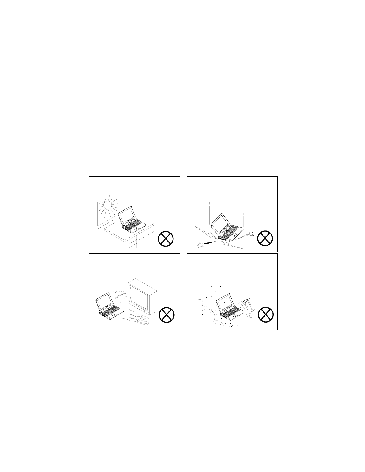
Handling the Computer
Do not expose it to excessive heat
or direct sunlight.
Do not expose it to strong magnetic
fields.
Do not expose your notebook
computer to any shock or vibration.
Do not leave it in a place where
foreign matter or moisture may
effect the system.
Page 4
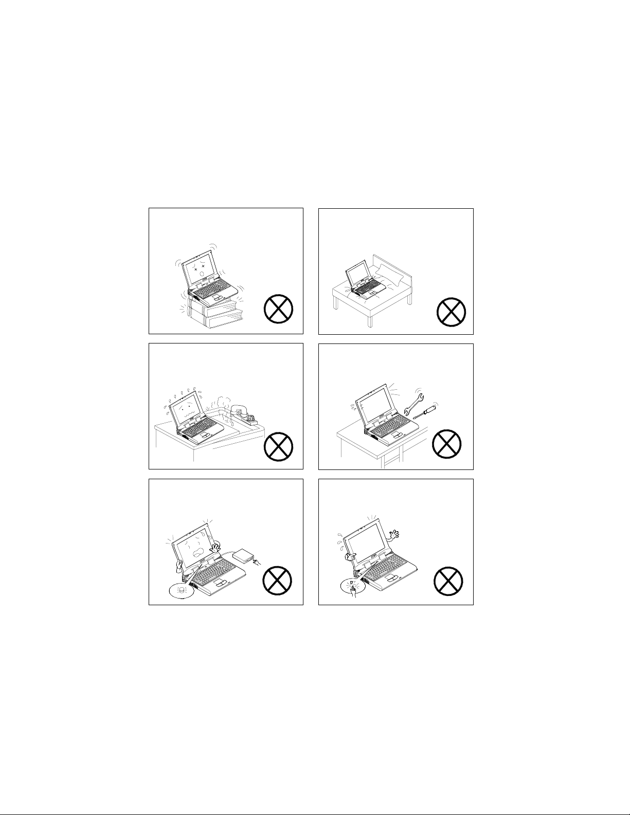
Do not place the computer on an
unstable surface.
Do not place the computer on any
surface which will block the vents.
Don’t use or store the computer in
a humid environment.
Do not turn off any peripheral devices when the computer is on
.
Do not disassemble the computer
by yourself.
Do not turn off the power until you
properly shutdown all programs.
Page 5
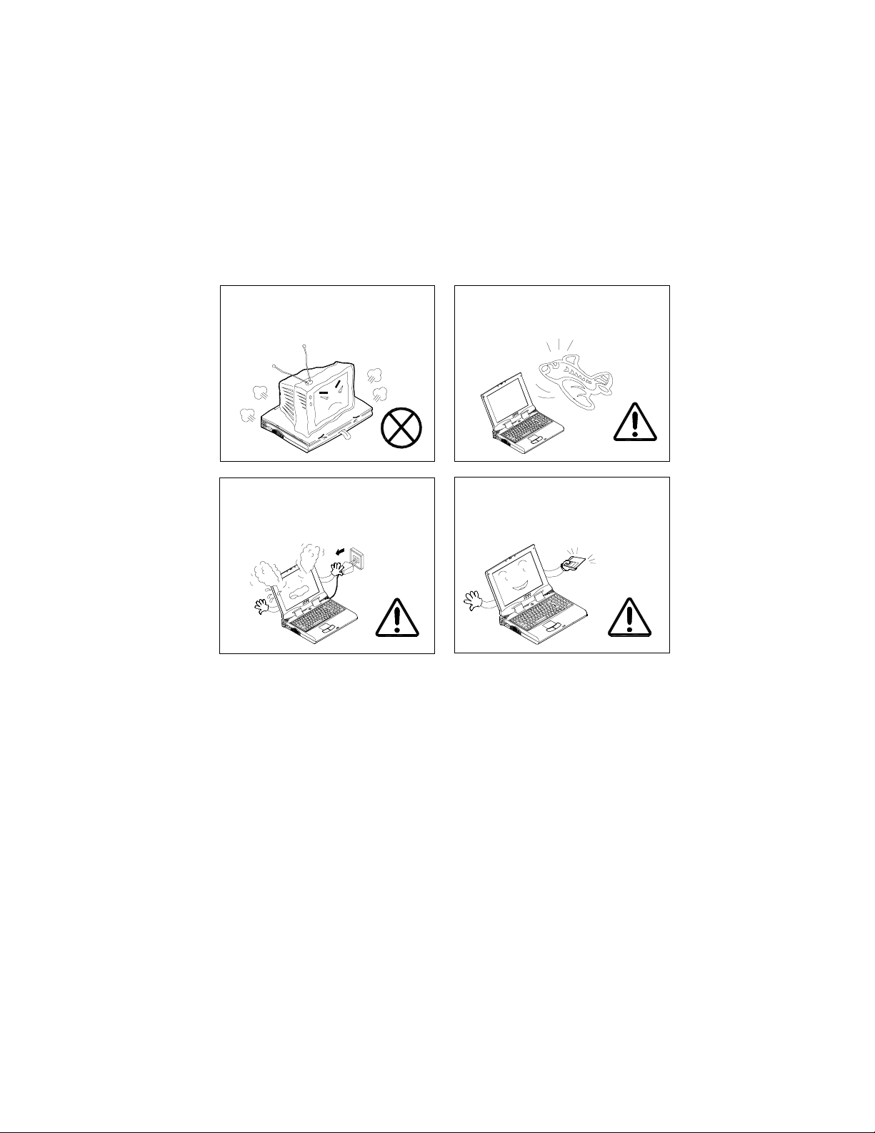
Do not place anything heavy on
the computer.
When traveling by air, follow the
airline’s instructions for in-flight
use.
If there is an unusual odor, heat or
smoke coming from your computer, unplug the cord.
Perform routine maintenance on
your computer.
Page 6

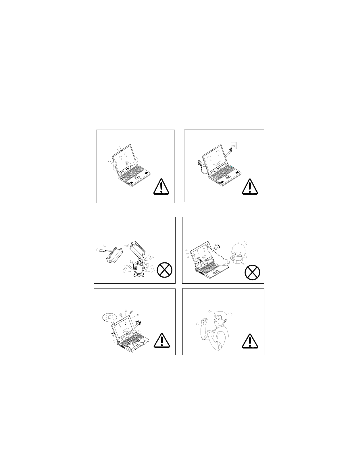
Handling of the Power Cord & Battery
Do not plug in the power cord if
you are wet.
Do not place heavy objects on the
power cord.
Keep the battery away from any
metal appliances.
Do not use the power cord if it is
broken.
Do not touch the battery contacts
with your hands or any metal objects.
Affix tape to the battery contacts
before disposing of the battery.
Page 7
Handling of Peripheral Devices
Use only approved brands of peripheral devices.
Other reminders
Do not throw the computer or accessories into a fire.
Remember to periodically save
your data. Data may be lost if the
battery is depleted.
Unplug the power cord before attaching any peripheral devices.
Do not touch the poisonous liquid if the LCD panel breaks.
Take periodic breaks if you are
using the computer for long periods of time.
Page 8
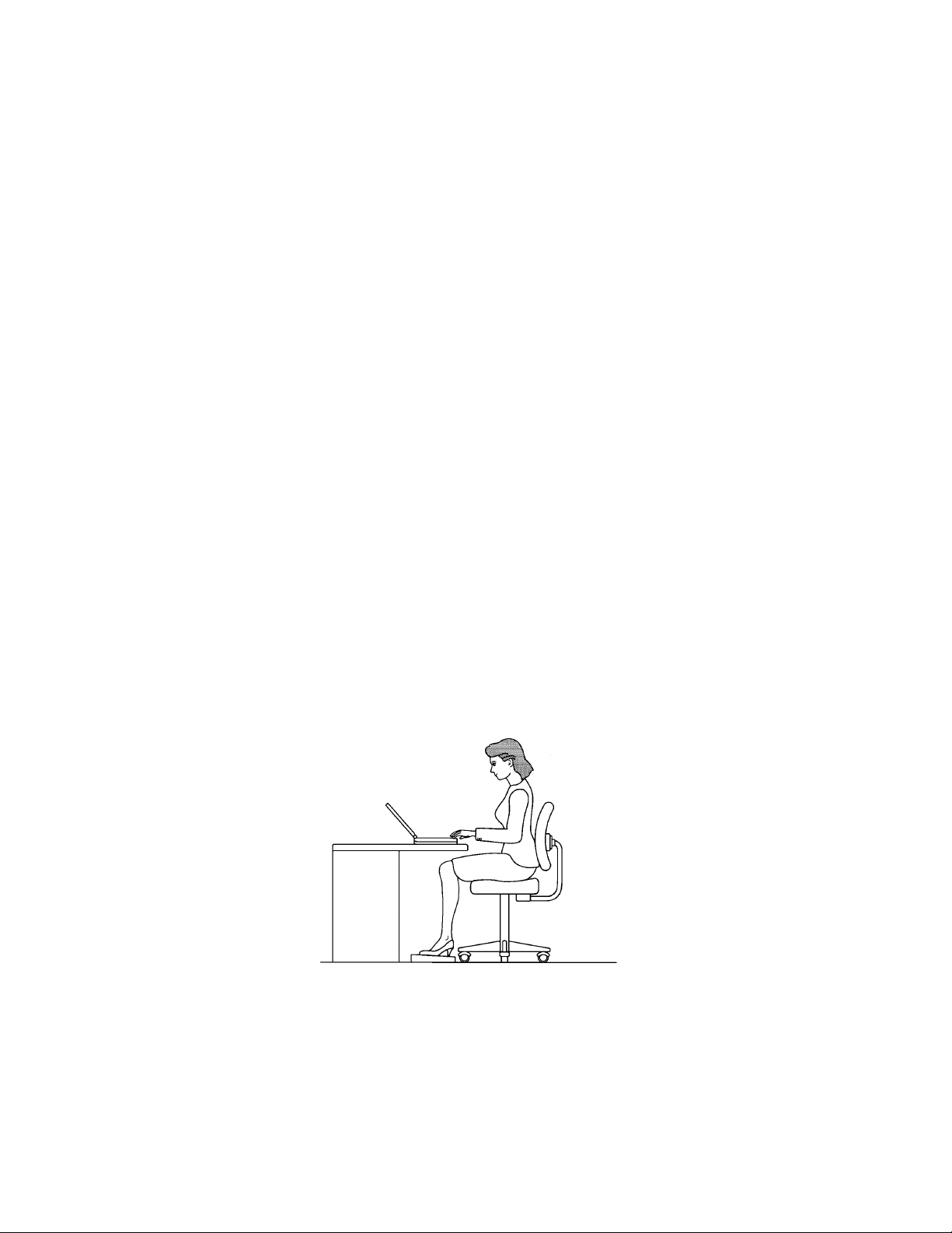
Developing Good Work Habits
Developing good work habits are important if you need to work in
front of the computer for long periods of time. Improper work
habits can result in discomfort or serious injury from repetitive
strain to your hands, wrists or other joints. The following tips
should help reduce the strain:
– Adjust the height of the chair and/or desk so that the
keyboard is at or slightly below the level of your elbow.
Keep your forearms, wrists, and hands in a relaxed
position.
– Your knees should be slightly higher than your hips.
Place your feet flat on the floor or on a footrest if
necessary.
– Use a chair with a back and adjust it to support your
lower back comfortably.
– Sit straight so that your knees, hips and elbows form
approximately 90 degree angles when you are working.
Page 9

Remember to:
– Alter your posture frequently.
– Stretch and exercise your body several times a day.
– Take periodic breaks when you work at the computer for
long periods of time. Frequent and short breaks are
better than fewer and longer breaks.
Lighting
Proper lighting and comfortable display viewing angle can reduce
eye strain and muscle fatigue in your neck and shoulders.
– Position the display to avoid glare or reflections from
overhead lighting or outside sources of light.
– Keep the display screen clean and set the brightness and
contrast to levels that allow you to see the screen clearly.
– Position the display directly in front of you at a
comfortable viewing distance.
– Adjust the display viewing angle to find the best position.
Page 10

Table of Contents
Chapter 1. Getting Started ................................. 1-1
Checking the Items .......................................................1-3
Opening the LCD display..............................................1-3
T op V iew with Display Open..........................................1-5
LCD Display ......................................................................1-5
Power Button.....................................................................1-5
Three Hot-key Buttons ......................................................1-5
TrackPad and Buttons.......................................................1-5
Stereo Speakers ...............................................................1-5
LED Power Indicators .......................................................1-5
Keyboard...........................................................................1-5
Microphone........................................................................1-5
LED Status Indicators .......................................................1-5
Right Side View............................................................ 1-7
5.25" CD-ROM or DVD-ROM Drive ..................................1-7
Vent ...................................................................................1-7
Security Slot ......................................................................1-7
Rear View ....................................................................1-9
DC-in Jack ........................................................................1-9
External Monitor (CRT) Port..............................................1-9
Parallel Port.......................................................................1-9
Vent ...................................................................................1-9
Serial Port .........................................................................1-9
Dual USB Ports.................................................................1-9
PS/2 Type Port..................................................................1-9
LAN Jack/Phone Jack (optional)........................................1-9
Left Side View............................................................ 1-11
Microphone-in Jack ......................................................... 1-1 1
Speaker-out Jack ............................................................ 1-1 1
Audio Volume Control...................................................... 1-11
PC Card Slot ................................................................... 1-11
Infrared Port .................................................................... 1-11
3.5" FDD (Floppy Disk Drive).......................................... 1-11
Page 11

Bottom View...............................................................1-12
RAM Cover ......................................................................1-12
Battery Pack Cover .........................................................1-12
Chapter 2. Using the Computer .........................2-1
The Power Sources ......................................................2-3
AC Power Adapter.............................................................2-3
Battery Pack......................................................................2-3
Turning on the Computer............................................... 2-5
LED Indicators...................................................................2-5
The Hard Disk Drive (HDD) .......................................... 2-7
Removing the HDD ...........................................................2-7
Inserting the HDD..............................................................2-9
The Floppy Disk Drive (FDD)........................................2-9
Inserting/Removing Diskettes ...........................................2-9
The CD-ROM/DVD-ROM............................................ 2-11
Loading Compact Discs .................................................. 2-11
Handling Compact Discs ................................................ 2-11
The PC Card Slot .......................................................2-13
Inserting PC Cards..........................................................2-13
Removing PC Cards .......................................................2-13
The Ho t Key................................................................ 2-15
Three Hot-Key Buttons....................................................2-15
Function Keys .................................................................2-17
The Numeric Keypad ..................................................2-17
Chapter 3. Attaching Peripherals...................... 3-1
PS/2 Keyboard or Mouse .............................................3-3
Paralle l Printer..............................................................3-3
Serial Mouse or Device ................................................ 3-5
External Monitor (CRT) .................................................3-5
USB Compatible Device .............................................. 3-7
Network Cable or Phone Line (Optional) .......................3-7
Security Lock................................................................3-8
Chapter 4. Upgrading the Computer ................ 4-1
Replacing the HDD.......................................................4-3
Upgrading the Memory .................................................4-3
Page 12

Installing a Memory Module ...............................................4-5
Removing a Memory Module.............................................4-7
Adding or Replacing the Processor .............................. 4-7
Removing the Processor ..................................................4-7
Installing the Processor...................................................4-11
CPU Clock Jumper Setting.........................................4-13
Accessing the CPU Clock Jumper Switch (SW7) ..........4-13
CPU Voltage Jumper Setting......................................4-13
Accessing the CPU Voltage Jumper Switch (SW6)........4-14
Chapter 5. BIOS Utilities ...................................5 - 1
Power On Self T est (POST) ........................................ 5 - 3
POST Message: Normal Operation ................................5 - 3
POST Message: Error Detected .....................................5 - 3
System Configuration Utility ........................................ 5 - 5
Information in the System Configuration Utility ................5 - 5
Initiating the System Configuration Utility.........................5 - 5
Working with the Menu Bar .............................................5 - 7
Working with the Pull-down Menu ...................................5 - 7
Features of the System Configuration Utility ................ 5 - 9
Startup Menu...................................................................5 - 9
Memory Menu................................................................ 5 - 11
Disks Menu ...................................................................5 - 13
Components Menu........................................................5 - 15
Power Menu ..................................................................5 - 17
Exit Menu.......................................................................5 - 21
Power Management ................................................. 5 - 21
Advanced Power Management (APM 1.2).....................5 - 21
Advanced Configuration and Power Interface (ACPI)....5 - 21
Global Standby..............................................................5 - 21
Hard Disk Standby ........................................................5 - 23
Suspend and Resume ..................................................5 - 23
Powered On Suspend (POS) ....................................... 5 - 23
Resume from POS Mode..............................................5 - 23
Suspend To Disk ...........................................................5 - 23
Resume from Suspend To Disk Mode ..........................5 - 24
Chapter 6. Installing Drivers .............................. 6-1
Page 13

Preparation for a New Notebook................................... 6-3
Installing Windows 98 SE (For Reference Only) ............ 6-3
Installing Windows 2000 (For Reference Only) .............. 6-5
Installing Drivers in Windows 98 SE.............................. 6-5
Step 1: Installing the VGA Driver .......................................6-5
Step 2: Installing the Audio Driver......................................6-5
Step 3: Installing the Hot Key Driver ..................................6-7
Step 4: Installing the LAN Driver ........................................6-7
Step 5: Installing the PCMCIA Driver (Optional) ................6-7
Step 6: Installing the Modem Driver (Optional) ..................6-7
Installing Drivers in Windows 2000................................6-9
Step 1: Installing the SiSIDE Utility ....................................6-9
Step 2: Installing the VGA Driver .......................................6-9
Step 3: Installing the Audio Driver......................................6-9
Step 4: Installing the Hot Key Driver ................................6-1 1
Step 5: Installing the LAN Driver ...................................... 6-1 1
Step 6: Installing the PCMCIA Driver (Optional) .............. 6-11
Step 7: Installing the Modem Driver (Optional) ................6-1 1
Installing Drivers in Windows NT4.0 ............................6-13
Step 1: Installing the VGA Driver .....................................6-13
Step 2: Installing the Audio Driver....................................6-13
Step 3: Installing the Hot Key Driver ................................6-13
Step 4: Installing the LAN Driver ......................................6-13
Step 5: Installing the Modem Driver (Optional) ................6-14
Chapter 7. Troubleshooting ..............................7-1
Audio............................................................................ 7-3
Battery.......................................................................... 7-3
Boot Password.............................................................7-5
CD ............................................................................... 7-5
Floppy Disk Drive (FDD) .............................................. 7-5
Hard Disk Drive (HDD)................................................. 7-5
Hardware Installation..................................................... 7-7
LCD Panel....................................................................7-7
Memory Module ............................................................ 7-7
PC Card....................................................................... 7-9
Page 14

Power........................................................................... 7-9
Printer .......................................................................... 7-9
Appendix A. Specification ................................. A-1
Appendix B. Battery Information...................... B-1
Appendix C. Different Versions of KeyboardsC-1
Appendix D. Installing WinDVD Player (Optional)
D-1
Glossary ..................................................................1
Page 15

Chapter 1. Getting Strarted
Chapter 1. Getting Started
This chapter provides you with the basic introduction about the computer and
its features, just like a guide tour. Now lets take a look at the computer from
different views.
The chapter includes:
! Checking the Items
Opening the LCD Display
!
Top View with Display Open
!
Right Side View
!
Rear View
!
Left Side View
!
Bottom View
!
1-1
Page 16

User’s Manual
Checking the Items
Carefully remove everything from the shipping box and check the items one
by one. If any item is missing or damaged, contact your dealer immediately .
1 Notebook Computer
2 Carrying Bag
3 Power Adapter
4 Power Cord
5 User’s Manual
6 Battery Pack (installed
inside the computer)
7 Driver Utilities (CD-ROM
disk)
1-2
Page 17
Chapter 1. Getting Strarted
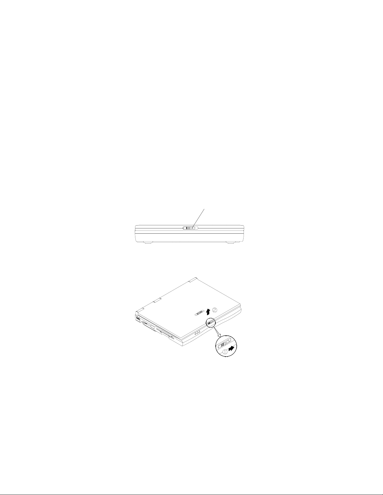
Opening the LCD display
1) Move the cover latch to the right to release the top cover.
2) Lift the top cover to reveal the LCD panel and keyboard.
3) Adjust the LCD panel to a comfortable viewing angle.
4) Press the power button to power up the system.
Cover latch
1-3
Page 18

User’s Manual
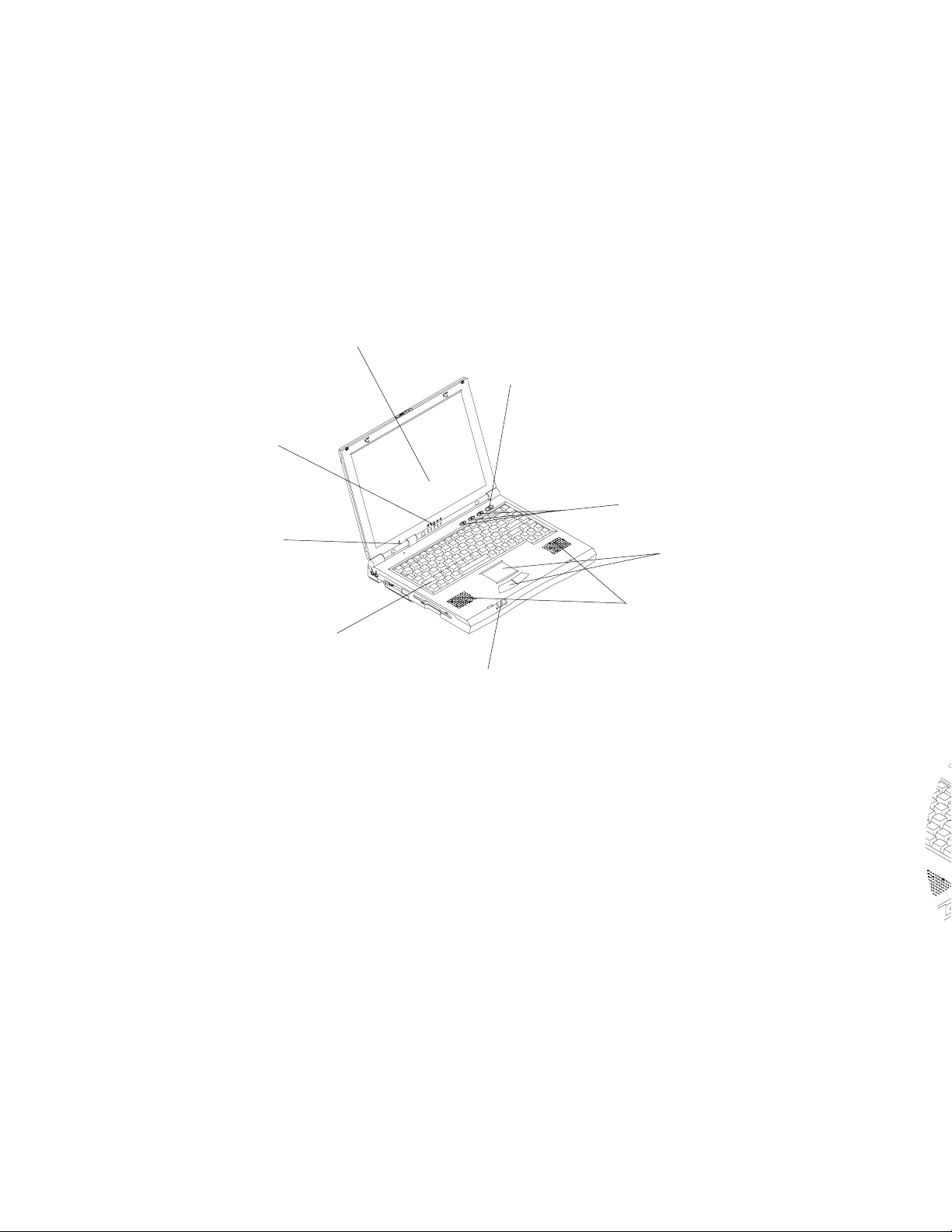
T op View with Display Open
LCD Display
The Notebook comes with a TFT LCD (Liquid Crystal Display)
display . Depending upon the model you have purchased, the display
can be either a 13.3”/14.1” XGA TFT color panel.
Power Button
Pressing this button turns your notebook computer on or off. The
Power Button can also be used as a Suspend/Resume button when
pressed less than four seconds (if configured appropriately in System Configuration Utility).
Note: After turning your notebook computer off, wait 5
seconds at least before turning it on again.
Three Hot-key Buttons
The computer provides you with three friendly hot keys allowing easy
access to internet, e-mail and an application frequently used by
yourself.
1-4
TrackPad and Buttons
The pointing device features a sensitive glide pad for precise movements. It functions the same way as a two-button mouse: the right
touch pad button is the same as the right mouse button; the left
touch pad button is the same as the left mouse button.
Page 19

Chapter 1. Getting Strarted
Stereo Speakers
Two built-in speakers provide rich, stereo sound.
LED Power Indicators
These indicators display the current power source and status of the
computer. For more information please refer to Chapter 2 LED
Power Indicators.
Keyboard
This A4-Sized Win98 keyboard has an embedded numeric keypad.
It also has many of the same features as a full-sized desktop
keyboard and can easily be replaced with a non-English keyboard.
Microphone
With the built-in microphone you can proceed any recording task
through an appropriate application on your notebook computer.
LED Status Indicators
These LED indicators display the system's operational status. Refer
to Chapter 2 LED Status Indicators for more information.
1-5
Page 20
User’s Manual
*
"
#
$
)
%
&
(
'
1. LCD dispaly
2. Power button
3. Three hot-key buttons
4. TrackPad and buttons
5. Stereo speakers (built-in)
6. LED power indicators
7. Keyboard
8. Microphone (built-in)
9. LED status indicators
1-6
Page 21
Chapter 1. Getting Strarted
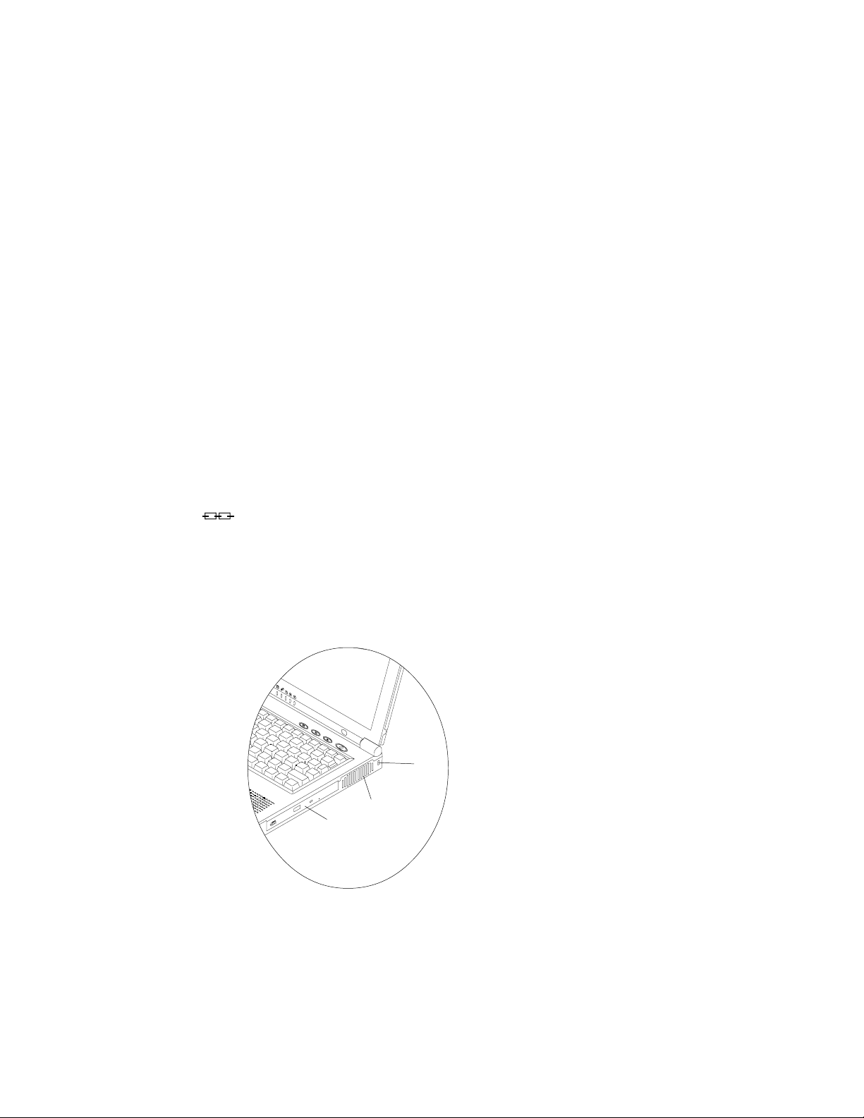
Right Side View
5.25" CD-ROM or DVD-ROM Drive
The notebook comes standard with a 24X-speed 5.25” CD-ROM drive
or a DVD-ROM drive (12.7mm height) depending on the model you
purchased. (Please refer to Chapter 2 for more information on using
the CD-ROM or DVD-ROM.)
Vent
It enables airflow to prevent the notebook from overheating.
Security Slot
A lock for your computer can be attached to this slot to prevent
possible theft.
"
#
$
1. CD-ROM/DVD-ROM
2. Vent
3. Security Slot
1-7
Page 22

User’s Manual
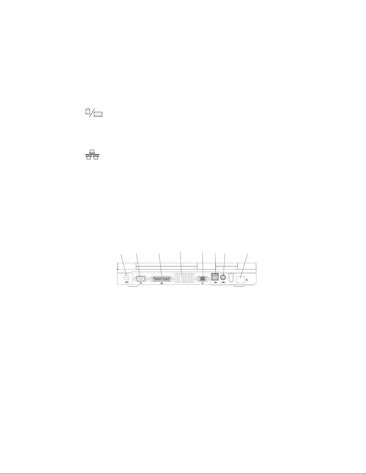
Rear View
DC-in Jack
The AC adapter is plugged into this jack to power on your notebook.
External Monitor (CRT) Port
The D-sub port uses a 15-pin connector allowing you to connect an
external CRT monitor . Simultaneous display on the LCD display
and an external CRT monitor is possible.
Parallel Port
The Parallel Port uses a 25-pin female connector for connection of
a parallel printer or other parallel devices. This parallel port supports ECP (Extended Capabilities Port) and EPP (Enhanced
Parallel Port) 1.7/1.9 modes.
1-8
Vent
It enables airflow to prevent the notebook from overheating.
Serial Port
The RS-232C 16550A compatible serial port (COM1) uses a 9-pin
male connector to connect an external serial device, such as a
serial mouse, printer or fax/modem.
Dual USB Ports
The dual USB (Universal Serial Bus) ports make adding peripheral
devices easier.
Page 23
Chapter 1. Getting Strarted
PS/2 Type Port
The PS/2 type port uses a 6-pin connector and enables you to
connect an external PS/2 type mouse or keyboard.
LAN Jack/Phone Jack (optional)
The jack is used to support the integrated LAN function and an
optional built-in modem. Depending on the model you purchased,
the feature of using the jack as a phone jack might be or might not
be available. For more information on the LAN/Phone jack please
refer to Chapter 4.
"
#
$
1. DC-in jack
2. Serial port
3. Parallel port
4. Vent
5. External monitor (CRT) port
6. Dual USB ports
7. PS/2 type port
8. LAN jack/Phone jack (optional)
%
&
'
(
)
1-9
Page 24

User’s Manual
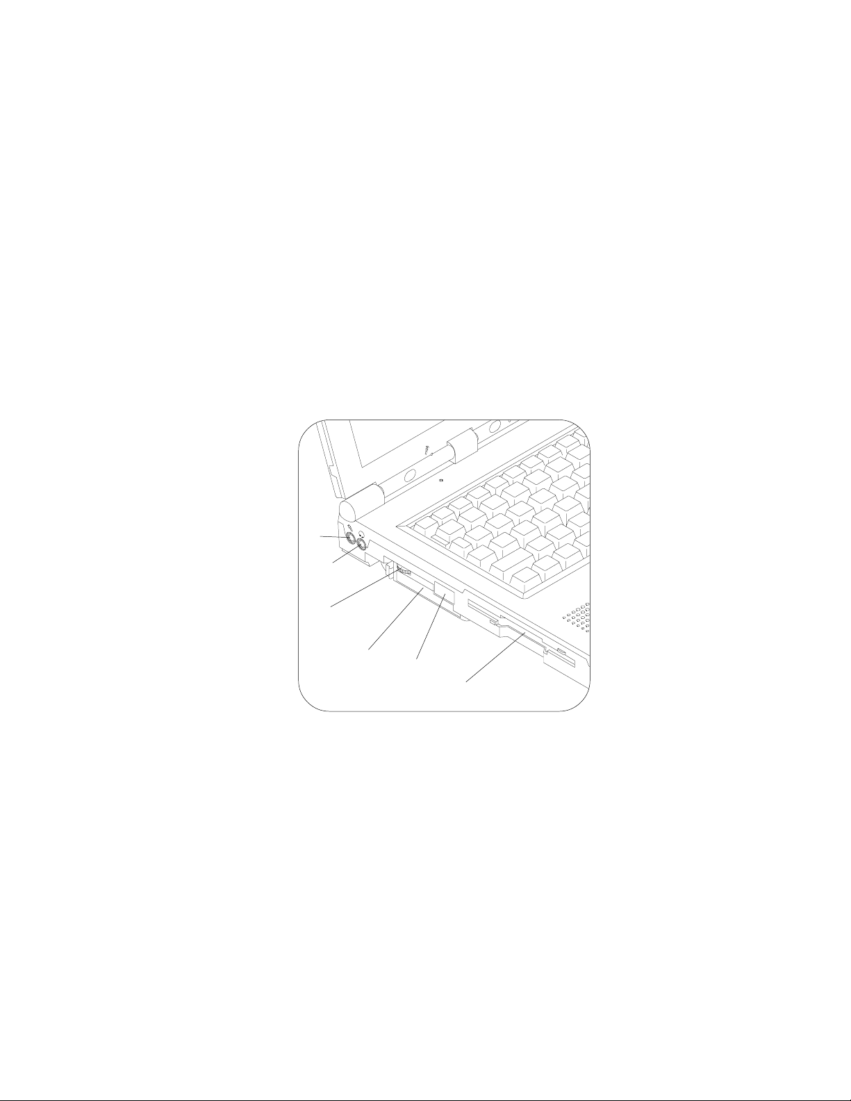
Left Side View
Microphone-in Jack
A microphone can be connected to your notebook via this jack.
Besides, the jack also supports a S/P-DIF (Sony/Philips Digital
Interface Format) output, which allows you to connect your DVDcapable PC to a Dolby AC-3 compatible receiver. In that way , the
digital audio data from the DVD-ROM will be transported to the
surround sound system and offers you a spacious sound effect.
Please note this S/P-DIF output feature is available only in Windows 98 after the Audio driver is installed. Refer to Chapter 6 for
instructions of installation and settings.
Speaker-out Jack
Headphone or speakers can be attached to the computer through
this jack.
1-10
Audio Volume Control
T o increase/decrease the volume, adjust the audio volume control.
PC Card Slot
The notebook provides one Type-II PC card slot. The slot also
supports CardBus mode.
Infrared Port
This port allows wireless communications with an infrared-compatible device. The Infrared port supports IrDA (HPSIR) 1.1 and ASKIR
(Sharp standard) mode. For further information, please refer to the
manual of the infrared device you wish to connect.
Page 25
Chapter 1. Getting Strarted
3.5" FDD (Floppy Disk Drive)
The drive is a 3.5”, 3-mode, 1.44 MB fixed floppy disk drive. For more
information on using the floppy disk drive, please refer to Chapter 2.
"
#
$
%
&
1. Microphone-in jack
2. Speaker-out jack
3. Audio volume control
4. PC card slot
5. Infrared port
6. Floppy disk drive
'
1-11
Page 26
User’s Manual
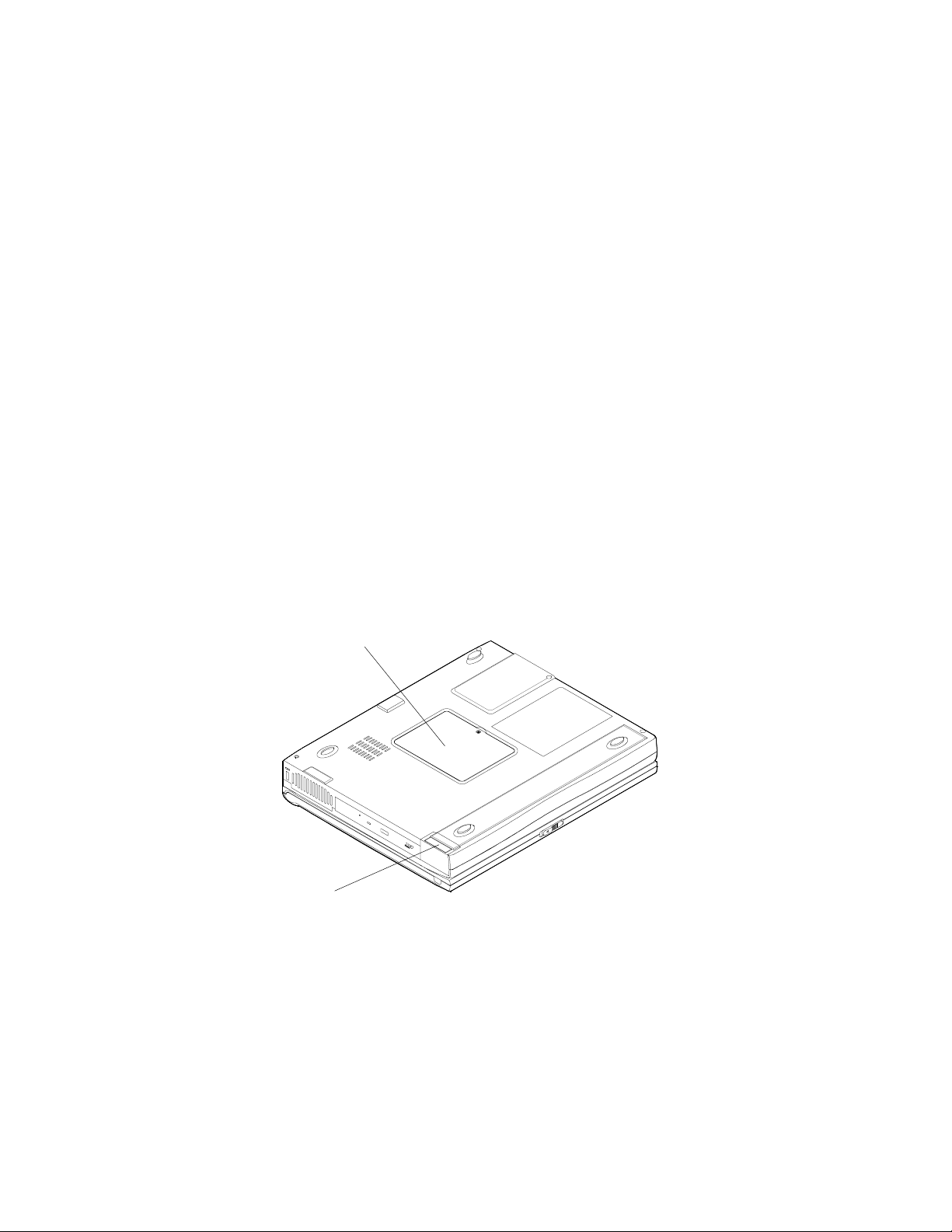
Bottom View
RAM Cover
The cover secures the installed RAM modules. For further information
on removing or inserting the RAM modules, please refer to Chapter 4.
Battery Pack Cover
The cover secures the battery pack in its bay .
"
1-12
1. RAM cover
2. Battery pack cover
#
Page 27

Chapter 2. Using the Computer
Chapter 2. Using the Computer
Y our notebook computer can be used almost anywhere, in the home, office, or
on the road. T o learn about how to power your computer , how to operate your
computer and the features available, please read this chapter.
The chapter includes:
!
The Power Sources
! Turning on the Computer
! The Hard Disk Drive
! The Floppy Disk Drive
! The CD-ROM/DVD-ROM
! The PC Card Slot
! The Hot Key
! The Numeric Keypad
2-1
Page 28
User’s Manual
The Power Sources
The computer can be powered by either an AC adapter or a battery pack depending on where you want to use it.
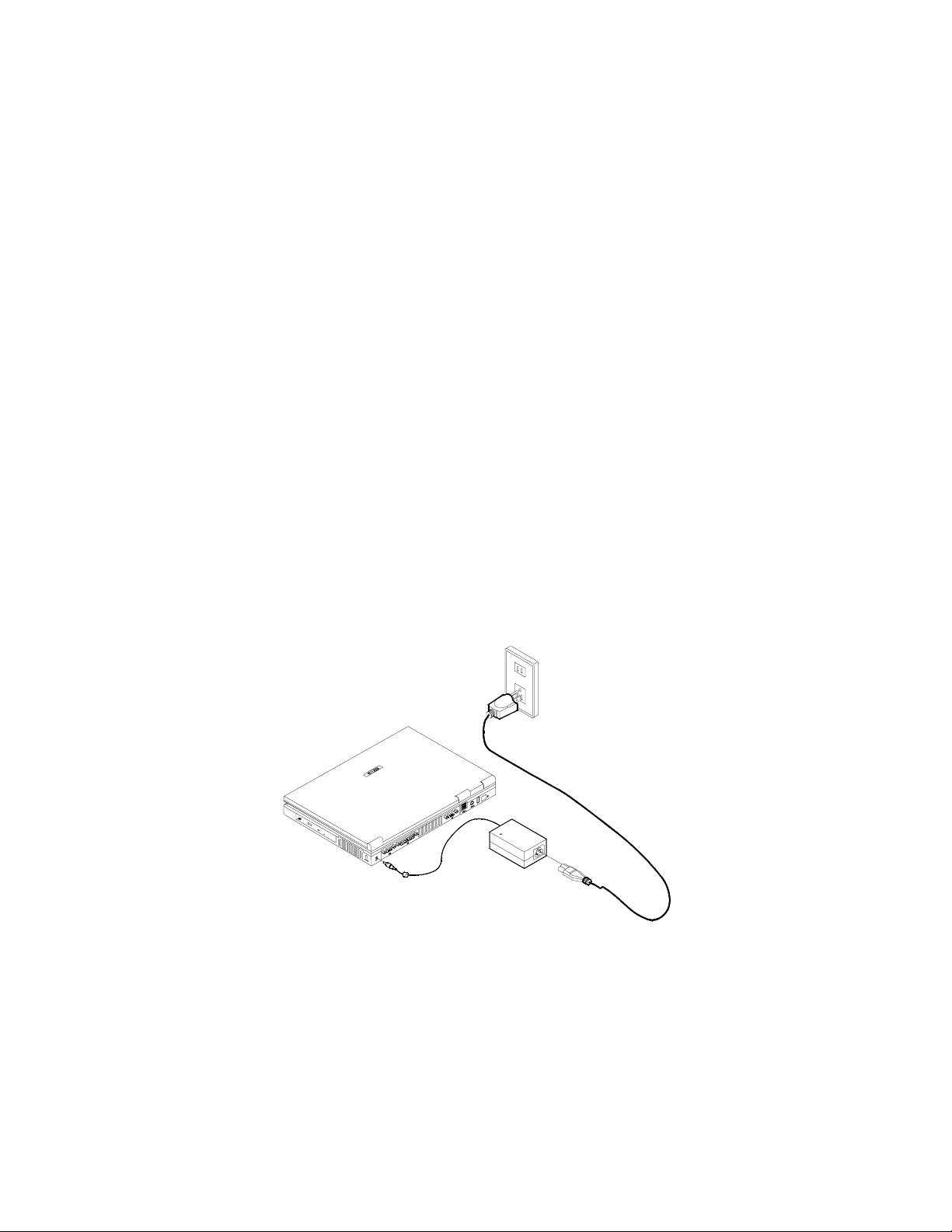
AC Power Adapter
Use only the power adapter that comes with your computer. An incorrect type
of power adapter will cause damages to the computer and its components.
1) Plug the power adapter cord into the DC-in jack on the rear panel of
the computer.
2) Connect the power adapter with the power cord.
3) Plug the power cord into a properly grounded outlet.
2-2
Page 29

Chapter 2. Using the Computer
Battery Pack
The battery pack allows you to use your notebook computer while you are on
the road or an electrical outlet is unavailable. The battery life differs based on
the applications and the configuration you're using. T o increase battery life, let
the battery discharge completely before recharging.
Please don’t remove the battery pack from the computer. If it is necessary to
remove the battery pack, please contact your dealer for help.
Recharging by AC Power
The battery pack automatically recharges when it is installed into the computer that is plugged with an AC power supply . You can still use the computer when it is recharging. T o fully recharge the battery will take several
hours and may be slightly longer if the computer continues to be used while
the battery is recharging. (Please refer to LED Power Indicators in this
chapter for more information on the battery charge status.)
Proper Handling of the Battery Pack
DO NOT disassemble the battery pack under any circumstances.
DO NOT expose the battery to fire or high temperatures, it may ex-
plode.
DO NOT connect the metal terminals (+, -) together.
(For more information on how to maintain the battery pack, refer
to Appendix B.)
2-3
Page 30

User’s Manual
Turning on the Computer
Now you are ready to begin using your new notebook computer. To turn it on
simply press the power button in the right top of the front panel.
Power button
The Power Button can also be used as a Suspend/Resume hot-key button if
pressed less than four seconds after appropriately configured in the SCU.
(Please refer to Chapter 5, BIOS Utilities, for more information.)
LED Indicators
There are two sets of LED indicators (LED Power Indicators/LED Status Indicators) on your computer that will show you helpful information about the current
status of the computer.
2-4
Page 31

Chapter 2. Using the Computer
LED Power Indicators
The LED power indicators located on the front side display the power status.
LED power indicators
Icon Color Description
Green The computer is turned on.
Blinking Green
Yellow
Blinking Yellow The battery is being charged.
No light
Blinking Yellow Battery power is critically low.
The system enters the configured
suspend mode.
The AC power is plugged in or battery
power is full.
The AC power is being used or battery
power is not critically low.
Note: When the battery is critically low, immediately connect the AC adapter
to the computer or save your work; otherwise, the unsaved data will be lost
when power is depleted.
2-5
Page 32

User’s Manual
LED Status Indicators
Once your computer is on and in use, the LED status indicators will display the
system's operational status.
LED status indicators
Icon Color Description
Green Scroll Lock is activated.
Green Caps Lock is activated.
Green Num Lock is activated.
Green
Green Floppy disk drive is being accessed.
The hard disk/CD-ROM/DVD-ROM drive is
being accessed.
Note: To enable/disable the Scroll Lock feature, press the Fn and Scr Lk key
simultaneously.
2-6
Page 33

Chapter 2. Using the Computer
The Hard Disk Drive (HDD)
The hard disk drive is used to store your data internally in the notebook computer. It is mounted in a removable case and can be taken out to accommodate
other 2.5” IDE hard disk drives with a height of 12.7 mm or 9.5 mm. The system
supports DMA mode 2, PIO mode 4, and A T A-33/A T A-66/ATA-100 IDE HDD.
Note: Before removing the HDD, please check your dealer if this will
VOID your warranty.
Removing the HDD
1) T urn off the computer .
2) Press the four keyboard latches at the top of the keyboard to elevate
the keyboard from its normal position.
3) Carefully raise and set the keyboard aside.
4) Locate and unscrew the HDD.
5) Disconnect the HDD connector gently from the mainboard.
6) Lift the HDD out of the computer.
2-7
Page 34

User’s Manual
HDD connector
HDD Top View
Inserting the HDD
1) Turn off the computer.
2) Press the four keyboard latches at the top of the keyboard to elevate
the keyboard from its normal position.
3) Carefully raise and set the keyboard aside.
4) Place the HDD into the computer.
5) Connect the HDD connector securely to the mainboard by gently
pressing the HDD.
6) Screw up the HDD.
7) Reinstall the keyboard.
2-8
Page 35

Chapter 2. Using the Computer
The Floppy Disk Drive (FDD)
The computer is equipped with a fixed 1.44 MB, 3.5” floppy disk drive module.
It is usually designated drive A by default and can be used as a boot device if
properly set in the SCU (please refer to Chapter 5, BIOS Utilities).
Inserting/Removing Diskettes
When using the floppy drive, always insert your floppy diskette with label-side
facing up. To remove the inserted diskette, press the eject button on the topright corner of the floppy drive.
Eject button
2-9
Page 36

User’s Manual
The CD-ROM/DVD-ROM
The notebook computer comes standard with a 24X speed 5.25” CD-ROM
drive or a DVD-ROM (depending on the model you purchased). It is usually
labeled drive D and may be used as a boot device if properly set in the SCU
(please refer to Chapter 5, BIOS Utilities).
Loading Compact Discs
T o insert a CD disk, press the Open Button and carefully place a CD disk onto
the Disc tray with label-side facing up (see below). Push the CD tray in and you
are ready to start. The Busy Indicator will light up while data is being accessed
or while an audio CD is playing. If power is unexpectedly interrupted, insert an
object such as a straightened paper clip into the Emergency Eject hole to open
the tray .
Note: When manually ejecting a CD disk, DO NOT use a sharpened pencil or
similar object that may break and become lodged in the hole.
2-10
Disc tray
Emergency eject hole
Busy indicator
Open button
Page 37

Chapter 2. Using the Computer
Handling Compact Discs
Proper handling of your CDs will prevent them from being damaged. Please
follow these advices listed below to make sure that the data stored on your CDROM disks can be accessed.
Remember to:
- Hold the CD by the edges; do not touch the surface of the disc.
- Use a clean, soft, dry cloth to remove dust or fingerprints.
- Do not write on the surface with a pen.
- Do not attach paper or other materials to the surface of the disk.
- Do not store or place the CD in high-temperature areas.
- Do not use benzene, thinners, or other cleaners to clean the CD.
- Do not bend the compact disc.
- Do not drop or subject the CD to shock.
2-11
Page 38

User’s Manual
The PC Card Slot
The computer is equipped with one PC card slot (previously referred to as
PCMCIA). The slot supports one 3.3V/5V type II PC card and one 3.3V CardBus
card (PC Card 95).
Inserting PC Cards
Align the PC card with the slot and push the card in until it locks into place.
Removing PC Cards
To remove a PC card, simply press the eject button next to the slot.
Eject button
2-12
Page 39

Chapter 2. Using the Computer
After installation of Windows 98 or Windows 98 Second Edition, you
probably will find PC cards work abnormally and has one or a few of
the following situations:
- An exclamation mark appears in the PC card driver in Device
Manager
- PC cards don’t work at all
- PC card controllers are not enumerated
- PC card controllers are disabled on power-up
- PC card controllers are disabled when you resume the computer from Suspend mode
This is a problem caused by Microsoft Windows 98 (Second Edition)
product. T o resolve the problem, please contact your computer
dealer for a program file (PCI.vxd) to update your system driver.
For more information on this, refer to Microsoft’s article “CardBus Device Not Enumerated with TI 14xx or 44xx CardBus Controllers” (Ar-
ticle ID: Q233017) which can be found on Microsoft’s web site.
PC Card Problem in Windows 98
Note: After installation of Windows 98 (Second Edition), please install the
PCMCIA update file PCI.vxd immediately .
2-13
Page 40

User’s Manual
The Hot Key
The computer provides you with two sets of hot keys: three hot-key buttons on
the computer and the function key combinations on the keyboard.
Three Hot-Key Buttons
The computer offers three hot-key buttons for you to access the internet
functions or an user-defined application quickly . Y ou can activate the www
browser, an e-mail application and one application that you often use by
pressing the appropriate hot-key button. T o use the user-defined hot key ,
you need to install the Hot-Key driver. Refer to Chapter 6 for driver installation steps.
Activate the e-mail box.
Activate the internet browser.
Activate the user-specified application, for example, the Microsoft
Word or Excel.
2-14
Three hot-key buttons
Page 41

Chapter 2. Using the Computer
Note: After installing the hot-key driver, you may have to configure or change
the settings of the driver. To configure the driver, click the Hot-key driver’s icon
on the task bar with the right button, the following menu will appear.
Hot-key Driver Menu
T o use the user-defined hot key , you must configure “Application 1.”
T o specify an application for Application 1, follow these steps:
Select Application 1 and press Enter. A dialog box will appear on the screen.
Go to the directory where the desirable application program exists, click on the
program file, and then choose Open.
2-15
Page 42

User’s Manual
Keys Description
Fn + F3 Expand LCD display
Fn + F5 Turn audio on/off
Fn + F6 Toggle between CRT/LCD/LCD+CRT
Fn + F9 Decrease LCD brightness
Fn + F10 Increase LCD brightness
Fn + Esc Toggle between suspend / resume
Function Keys
Located on the bottom-left of the keyboard is the Fn key or Function key . The
Fn key allows you to change operational features instantly (Hot Keys).
When you use the following functions, press and hold the Fn key; then press
the appropriate function key (F3, F9, F10, etc....) located at the top of your
keyboard.
Note: The keyboard showed here is for American-English version only. For
Germany , French, Japanese and Chinese versions, please refer to Appendix C.
2-16
Page 43

Chapter 2. Using the Computer
The Numeric Keypad
A numeric keypad is integrated into the keyboard for easy numeric data input.
The keypad stands out by its blue typeface.
To use the keypad simply:
• Activate the Num Lock feature by pressing the Num Lock key .
• Press the desired number keys.
The Numeric Keypad
2-17
Page 44

Chapter 3. Adding Peripherals
Chapter 3. Attaching Peripherals
T o enhance your computer's capabilities, you can attach peripheral devices to
the computer using the ports or jacks located on the rear or side panel of the
computer. The chapter instructs you to connect diverse external devices to the
computer.
The computer supports:
! PS/2 Keyboard or Mouse
! Parallel Printer
! Serial Mouse or Device
! External Monitor
! USB Compatible Device
! Network Cable or Phone Line (Optional)
! Security Lock
3-1
Page 45

User’s Manual
PS/2 Keyboard or Mouse
The computer allows you to use a PS/2 keyboard or mouse connected to your
notebook computer. However, if the PS/2 device uses a 5-pin connector, you
should get a 5- to 6-pin PS/2 transfer cable to attach the device to the computer. (For more information about a PS/2 transfer cable, contact your dealer .)
Attach the external keyboard or mouse to the PS/2 port as shown below.
3-2
PS/2 transfer cable
Page 46

Chapter 3. Adding Peripherals
Parallel Printer
You can connect any standard Centronics parallel printer to your computer
through the parallel port.
T o connect a printer simply:
1) T urn off the computer .
2) Connect the cable to the parallel port on the rear of the computer ( ").
3) Tighten the screws that fasten the cable to the parallel port (#).
4) Insert the other end of the cable to the printer's connector.
5) Fasten the cable's connector.
6) Turn on both the printer and computer.
Note: You may also need to install the manufacturer-supplied driver for the
printer. Refer to the device’s user guide for more information. If the connected printer supports Enhanced Parallel Port (EPP) or Extended Capabilities Port (ECP) mode, please enter the System Configuration Utility (SCU) to
configure the required setting.
3-3
Page 47

User’s Manual
Serial Mouse or Device
The serial port features a 9-pin connector. You can connect any serial device
such as a serial mouse to this port.
To connect a serial device you must:
1) Turn off the computer.
2) Connect the cable to the serial port on the rear of the computer (").
3) Tighten the screws that fasten the cable to the serial port (#).
4) Turn on the computer.
Note: In addition, you may need to install the manufacturer-supplied driver for
the serial mouse. Refer to the device's user guide for more information.
3-4
Page 48

Chapter 3. Adding Peripherals
External Monitor (CRT)
The computer can support an external monitor up to 1600 x 1200 x 16M. The
external monitor can be used simultaneously with the LCD display turned on or
off. Y ou can set your computer to use an external monitor by pressing Fn + F6
key combination. For more information, refer to Function Keys in Chapter 2.
To install an external monitor you simply:
1) T urn off the computer .
2) Connect the cable to the CRT port on the rear of the computer (").
3) Tighten the screws that fasten the cable to the CRT port (#).
4) Insert the other end of the cable to the external monitor.
5) Turn on both the monitor and the computer.
3-5
Page 49

User’s Manual
USB Compatible Device
The computer offers dual USB ports for attaching one or two USB compatible
devices such as an USB keyboard, mouse, or other USB devices. Plug the
USB device into the USB port as shown below.
3-6
Page 50

Chapter 3. Adding Peripherals
Network Cable or Phone Line (Optional)
The notebook, which integrates the 10M/100Mbps LAN solution, comes standard with a LAN (Ethernet) jack for connection of a local area network (LAN).
With the on-board 10/100Mbps LAN support, you simply attach a network cable
to the LAN jack. This jack can also connect a phone cord to proceed modem
communications if the model you purchased comes with an internal modem
card already installed. For detailed information on the optional built-in modem
please check your dealer.
Note: To use the integrated LAN function and optional internal modem, you
need to install the supplied LAN and modem driver in the computer. Refer to
Chapter 6 for driver installation.
3-7
Page 51

User’s Manual
Security Lock
A security lock can be installed onto your notebook computer to help prevent
theft. T o install the security lock, wrap the cable around a desk or other immovable object, then insert the locking device into the jack located on the right side
of your notebook computer.
3-8
Page 52

Chapter 4. Upgrading the Computer
Chapter 4. Upgrading the Computer
This chapter contains the information about how to upgrade the notebook
computer or enhance its functions. Please follow the steps to upgrade your
computer, if you have any troubles or problems, you can contact your dealer
for further help. Before you upgrade the computer, you will need:
- A small crosshead or Phillips screwdriver
- A small regular screw driver.
- An antistatic wrist strap
Note: If you plan on replacing the processor or upgrading the memory you will
need to remove the heat sink. Anytime the heat sink is removed you will need
to replace the heat sink pad. Before proceeding make sure you have a replacement pad available which you will need when you reinstall the heat sink. A
replacement pad can be obtained from your vendor. Refer to the Installing the
processor section of this chapter for heat sink pad installation instructions.
Also make sure you wear an antistatic wrist strap to ground yourself before
working with or repairing the internal components. Static electricity may
damage the components.
The chapter includes:
! Replacing the HDD
! Updating the Memory
! Adding or Replacing the Processor
! CPU Clock Jumper Setting
! CPU Voltage Jumper Setting
4-1
Page 53

User’s Manual
Replacing the HDD
Note: Before replacing, please check you dealer if this will VOID your
warranty.
1) Remove the HDD along with its case from the computer (refer to
Removing the HDD in Chapter 2 for details).
2) Remove the two screws on the HDD connector board.
3) Gently disconnect the HDD connector board from the HDD being
careful not to bend any pins.
4) Remove the two screws on each side of the case.
5) Slowly remove the HDD from the case.
6) Place a new HDD into the case.
7) Hold the HDD firmly in place with two screws on each side.
8) Attach the HDD to the HDD connector board being careful not to
bend any pins.
9) Screw up the HDD connector board.
10) Place the HDD into the computer (refer to Inserting the HDD in
Chapter 2 for details.)
HDD case
Connector board
4-2
HDD
Page 54

Chapter 4. Upgrading the Computer
Upgrading the Memory
The computer has two memory sockets for 144-pin Small Outline Dual In-line
Memory Modules (SO-DIMM) and supports both PC-100/PC-133 SDRAM. The
main memory can be expanded up to 512MB based on 32/64/128/256MB types
with different combinations as below chart:
Bank A
(64-bit)
32 MB 32 MB 64 MB
64 MB Empty 64 MB
64 MB 32 MB 96 MB
64 MB 64 MB 128 MB
128 M B Empty 128 M B
128 M B 32 M B 160 M B
128 M B 64 M B 192 M B
128 M B 128 MB 256 M B
256 M B Empty 256 M B
256 M B 32 M B 288 M B
256 M B 64 M B 320 M B
256 M B 128 MB 384 M B
256 M B 256 MB
Bank B
(64-bit)
Power Total Size
3.3V
512 M B
The total memory size is automatically detected by the POST routine once you
turn on your computer.
4-3
Page 55

User’s Manual
Installing a Memory Module
1) Turn off the computer.
2) Turn the computer upside down.
3) Unscrew and remove the RAM cover .
4) Insert the memory module at a slight angle about 45° and fit its
connectors firmly into the bank (").
5) Press down the two edges of the memory module and lock it into
place (#).
6) Reinstall the RAM cover.
Note 1:
The memory socket near the rear side of the computer can only accept a
memory module up to around one inch
wide,
so insert the memory module that
is wider than one inch into the socket near the front side.
4-4
Page 56

Chapter 4. Upgrading the Computer
Note 2:
Make sure the memory connectors go into the bank when you are installing
the memory modules.
67.6 mm
connectors
Note 3:
If you upgrade your memory modules from PC-100 to PC-133 or vice versa,
you should also configure the CPU Clock jumper switch. Refer to “CPU
Clock Jumper Setting” later in this chapter for more information.
4-5
Page 57

User’s Manual
Removing a Memory Module
1) Turn off the computer.
2) T urn the computer over .
3) Remove the screw from the RAM cover.
4) Locate the memory sockets.
5) Gently pull the two latches outward on both ends of the module (").
6) The module will pop up (#).
7) Remove the memory module ($).
8) Install a new memory module if desired (refer to Installing a Memory
Module).
9) Reinstall the RAM cover.
4-6
Page 58

Chapter 4. Upgrading the Computer
Adding or Replacing the Processor
The mainboard can support a Intel® Celeron 500/550/600/650/700 MHz processor or a Intel® Mobile Pentium !!! 600/650/700/750/800/850 MHz processor
with SpeedStep® technology. The technology will lower power consumption
by lowering the processor’s clock speed and voltage when battery power is
being used. That way , the battery life will be much longer .
Since the computer uses µPGA2 package for the CPU type, you will need a
screw driver to open or lock the CPU into the motherboard. Please see below
for instructions:
Removing the Processor
1) T urn off the computer .
2) Press the four keyboard latches at the top of the keyboard to elevate
the keyboard from its normal position.
4-7
Page 59

User’s Manual
3) Carefully raise and set the keyboard aside.
4) Disconnect the keyboard cable from the computer: push the upper
part of the keyboard connector upward (") and then take the cable out
of the connector (#).
Keyboard connector
Keyboard cable
5) Unscrew, remove the heat sink
and disconnect the fan cable from
the motherboard.
4-8
O
L
Page 60

Chapter 4. Upgrading the Computer
6) Locate the processor and use a screw driver to rotate the arrow mark
until it aims at the side marked with the O letter . (O stands for “OPEN”.)
The side marked with O
O
L
Arrow mark
O
L
O
L
7) Lift up the processor carefully.
4-9
Page 61

User’s Manual
Installing the Processor
1) Turn off the computer.
2) Remove the keyboard and heat sink from the computer. (Please see
Removing the Processor for details.)
3) Align the samll triangle mark on the CPU corner with the one on the
corner of CPU socket and then place the CPU onto the CPU socket.
4) Use a screw driver to rotate the arrow mark until it aims at the side
marked with the L letter. (L stands for “LOCK”.)
O
L
O
L
The side marked with L
5) Adjust the CPU Clock and Voltage jumper switches if necessary .
(Please see “CPU Clock Jumper Setting” and “CPU Voltage Jumper
Setting” later in the chapter for details.)
4-10
Page 62

Chapter 4. Upgrading the Computer
Note: When reinstalling the heat sink, you will also have to replace the
heat sink pad. A heat sink pad can be obtained from your dealer. To
replace the pad, just peel off the old one and put on a new one.
.
heat sink pad
6) Install back the heat sink and keyboard. When you are installing the
keyboard,
make sure the keyboard cable goes into the keyboard
connector (") and then press down the upper part of the connector to
securely hold the cable (#).
4-11
Page 63

User’s Manual
CPU Clock Jumper Setting
After replacing the processor or upgrading the memory module, you may need
to configure the CPU clock jumper setting. The setting is listed below:
CPU Clock Setting T able
CPU SDRAM
Pentium !!!
PSB=100MHz
Pentium !!!
PSB=100MHz
PC-100
PC-133 ON OFF ON OFF
SW7-1 SW7-2 SW7-3 SW7-4
ON OFF OFF OFF
Accessing the CPU Clock Jumper Switch (SW7)
1) Turn off the computer.
2) Remove the keyboard and heat sink from the computer. (Please see
Removing the Processor for details.)
3) Locate and adjust the CPU Clock jumper switch.
O
L
4-12
Page 64

Chapter 4. Upgrading the Computer
CPU V oltage Jumper Setting
If your new processor which will be installed into the computer is with
SpeedStep® technology , you must configure the CPU voltage jumper setting.
The setting is listed below:
CPU Voltage Setting Table (Performance Mode)
Voltage SW6-1 SW6-2 SW6-3 SW6-4
2.00V
1.95V
1.90V
1.85V
1.80V
1.75V
1.70V
1.65V
1.60V
1.55V
1.50V
1.45V
1.40V
1.35V
1.30V
NO CPU
ON ON ON ON
OFF ON ON ON
ON OFF ON ON
OFF OFF ON ON
ON ON OFF ON
OFF ON OFF ON
ON OFF OFF ON
OFF OFF OFF ON
ON ON ON OFF
OFF ON ON OFF
ON OFF ON OFF
OFF OFF ON OFF
ON ON OFF OFF
OFF ON OFF OFF
ON OFF OFF OFF
OFF OFF OFF OFF
Caution: Y ou can adjust the jumper switches SW6 and SW7 if necessary , but
don’t change any setting of jumper switch SW8.
4-13
Page 65

User’s Manual
Accessing the CPU Voltage Jumper Switch (SW6)
1) Turn off the computer.
2) Remove the keyboard and heat sink from the computer. (Please see
Removing the Processor for details.)
3) Locate and adjust the CPU Voltage jumper switch.
O
L
4-14
Page 66

Chapter 5. BIOS Utilities
Chapter 5. BIOS Utilities
In this chapter you will learn about the Power On Self T est (POST) and how to
configure the system parameters using the System Configuration Utility (SCU).
The chapter includes:
! Power On Self Test (POST)
! System Configuration Utilities
! Features of the SCU
- Startup Menu
- Memory Menu
- Disks Menu
- Components Menu
- Power Menu
- Exit Menu
! Power Management
5-1
Page 67

User’s Guide
SystemSoft MobilePRO BIOS Version 1.01 (2482-00)-(R1.XX.prXX)
Copyright 1983-1996 SystemSoft Corp. All Rights Reserved
500 MHz Celeron with MMX CPU
CPU Microcode Update Rev 007h Complete
L2 Cache: 128 KB Installed
8 MB Video RAM
SystemSoft Plug-n-Play BIOS ver 1.17.01
Base Memory 000640 KB
Extended Memory 056320 KB
Total Memory 057344 KB
Shared Memory 008192 KB
Auto Detecting IDE Devices[Done]
<CTRL-ALT-S> to enter System Configuration Utility
INITIALIZING BOOT CD-ROM - CD-224E
INITIALIZING 2nd AT API - None
Power On Self T est (POST)
The system BIOS (Basic Input/Output System) performs a series of tests on
the system memory and key computer components every time the computer is
powered on. These tests are called the Power On Self T est (POST). Should an
error exist, the POST routine may halt execution (depending on the problem).
If no error exists, the POST will initialize the BIOS configuration, and boot
(start) the operating system.
POST Message: Normal Operation
You will see the following message if no error exists after the POST is performed:
Note: Y ou may press the Spacebar key to skip the memory test.
5-2
Page 68

Chapter 5. BIOS Utilities
SystemSoft MobilePRO BIOS Version 1.01 (2482-00)-(R1.XX.prXX)
Copyright 1983-1996 SystemSoft Corp. All Rights Reserved
500 MHz Celeron with MMX CPU
CPU Microcode Update Rev 007h Complete
L2 Cache: 128 KB Installed
8 MB Video RAM
SystemSoft Plug-n-Play BIOS ver 1.17.01
Base Memory 000640 KB
Extended Memory 056320 KB
Total Memory 057344 KB
Shared Memory 008192 KB
WARNING - FLOPPY DISK TRACK 0 F AILED
Auto Detecting IDE Devices[Done]
<CTRL-ALT-S> to enter System Configuration Utility
INITIALIZING BOOT CD-ROM - CD-224E
INITIALIZING 2nd A T API - None
<CTRL-ALT-S> to enter System Configuration Utility
Press F1 to Continue
POST Message: Error Detected
If an error is detected, you will see the following WARNING message. You may
press the F1 key to continue, or press the Ctrl-Alt-S keys simultaneously to
enter the System Configuration Utility .
5-3
Page 69

User’s Guide
System Configuration Utility
The System Configuration Utility (SCU) can be used to set your notebook’s
system parameters. Things like the system date and time or what your computer will do if it is turned on but not used are what you set in the SCU.
The settings are stored in a nonvolatile battery-backed CMOS RAM. This
simply means that your settings are saved even when the notebook is turned
off.
Information in the System Configuration Utility
Here is a list of the system settings which may be changed within the System
Configuration Utility.
Menu Menu items
Startup
Memory Cache Systems, VGA Shared Memory
Date and Time, Fast Boot, Boot Device, Display, Enable
Battery Low Beep, Enable LCD expand Mode, Enable Power
On Beep, Enable PNP OS Support, Display OEM logo,
Enable S/PDIF digital output, Boot Password, SCU
Password.
Disks Diskette Drives, IDE Settings.
Components
Power Enable Power Saving, Low Power Saving, Medium Power
Exit
COM Ports, LPT Port, PS/2 Mouse Port, Keyboard Numlock,
Keyboard Repeat
Saving, High Power Saving, Customize, Suspend Controls,
Resume Timer, Enable MODEM Ring Resume, Enable
Battery Low Suspend, CPU SpeedStep Control.
Save and Exit, Exit (No Save), Default Settings, Restore
Settings, Version Info.
5-4
Page 70

Chapter 5. BIOS Utilities
Initiating the System Configuration Utility
The System Configuration Utility (SCU) can be accessed by pressing the
Ctrl, Alt, and S keys simultaneously when you turn on your computer and
see this message:
<CTRL-AL T-S> to enter System Configuration Utility
This message lasts only a few seconds and if you don’t respond in time, the
computer will initiate the boot process. If you were unable to enter the SCU,
you must reboot the system and try again.
Note: During startup, if your computer has a logo screen or picture appear
instead of the POST screen, wait until a cursor appears in the top right corner
before hitting <CTRL-AL T-S> to enter the SCU.
SystemSoft SCU For SiS 630/540 chipset Aug 10, 2000 1:02:35 PM
Startup Memory Disks Components Power Exit
Devices
Floppy Drive A = 1.44 MB
Hard Drive C = 4327 MB
Hard Drive D = 0 MB
Hard Drive E = 0 MB
Hard Drive F = 0 MB
Serial Port 1 = COM 1, 3F8, IRQ 4
Serial Port 2 = COM 2, 2F8, IRQ 3
Parallel Port = LPT1, Addr 378, IRQ 7
System
CPU Clock = 550
MHz
Memory
Base = 640
KB
Extended = 56320 KB
Shadow = 64
KB
Reserved = 320 KB
Press <Alt> key to activate menus, and cursor keys to navigate. Mouse left button.
button, spacebar, and <Enter> keys accept menu item. Mouse right button and
<Esc> key cancel current action.
5-5
Page 71

User’s Guide
Working with the Menu Bar
Use these keys to begin working in the SCU.
Keys Action
Alt Highlights the menu bar.
Left arrow (←)
Right arro w (→)
Highlighted letters
Left mouse button
Down arrow (↓)
Spacebar
Enter
Right mouse button
Esc
Selects a menu bar option.
Opens the menu bar option.
Cancels current action.
Working with the Pull-down Menu
Once your desired menu bar item is highlighted, press Enter or the down arrow
to see the pull-down menu items. You move about the pull-down menu with
these keys:
Keys Action
Down/Up arrows (↓) ( ↑ )
Highlighted letters
Enter
Esc Closes the pull-down menu
Selects a pull-down menu item.
Enables/disables the specified function.
A (√) indicates the function is on.
and saves the changes.
5-6
Page 72

Chapter 5. BIOS Utilities
Some pull-down menu options have an arrow (!) to the right of the entry.
Choose these options by pressing Enter and another screen will be displayed.
Navigate the new screen with the following keys:
Keys Action
Tab Moves from one record to another.
Down/Up arrows (↓)( ↑ )
Spacebar Selects a field.
Enter Chooses <OK> to save any changes.
Esc Quits.
Changes the value of a field.
<Cance l> to i g n or e any changes.
5-7
Page 73

User’s Guide
Features of the System Configuration Utility
Startup Menu
Item Setting/Option Function
Date and Time
Fast Boot
Boot Device
Display
Enable Battery Low
Beep
Enable LCD Expand
Mode
Day/Month/Year
Hour/Minute/Second
Enable Initialize and quick ly boot the
Disable Disable the Fast Boot.
1st Boot
Device
nd
2
Boot
Device
rd
3
Boot
Device
LCD
CRT Activate an externa l monitor.
LCD + CRT Activate both the LCD and the
Enable A series of warning beeps will
Disable Disable the above.
Enable Stretch the display to fill the
Disable Disable the above.
Hard Disk C
CD-ROM Drive
Diskette A
Hard Disk C
CD-ROM Drive
Diskette A
Hard Disk C
CD-ROM Drive
Diskette A
Set the date and time.
system by skipping certain
diagnostic tests.
Specify t he system s 1st choice
for the boot drive.
Specify t he system s 2
choice for the boot drive.
Specify t he system s 3
for the boot drive.
Activate the system s LCD
panel.
CRT.
sound when the bat tery power
is low.
entire scre en of the LCD panel.
nd
rd
choice
5-8
Page 74

t
Startup Menu (continued)
Item Setting/Option Function
On Beep
Support
digital output
Boot Password
SCU Password
EnableEnable Power
Disable
EnableEnable PNP OS
Disable
EnableDisplay OEM logo
Disable
EnableEnable S/PDIF
Disable
Enter old Power-On
Password
Enter new Power-On
Password
Verify new Power-On
Password
Enable Password to
Power-On
Enter old Setup Password
Enter new Setup
Password
Verify new Setup
Password
Enable Setup Password
Enable or Disable Power On Beep.
Enable or Disable PNP OS Support.
Enable or Disable the feature of
displaying the OEM logo at boot.
Enable or Disable the S/P-DIF outpu
feature.
Set a password for booting the
computer.
Only users who enter a correct
password can boot the system.
Set a password for modifying the
SCU. Only users who enter the
correct password can change the
SCU.
Chapter 5. BIOS Utilities
5-9
Page 75

User’s Guide
Caution: If you choose to set a boot password, NEVER forget your password,
the consequences could be serious. If you cannot remember your boot password you must contact your vendor and you may lose all of the information on
your HDD.
SystemSoft SCU For SiS 630/540 chipset Aug 10, 2000 1:02:35 PM
Startup
Startup Memory Disks Components Power Exit
Date and Time !
Devices
Ö Fast Boot
Floppy Drive A = 1.44 MB
Boot Device !
Hard Drive C = 4100 MB
Display !
Hard Drive D = 0 MB
Ö Enable Battery Low Beep
Hard Drive E = 0 MB
Ö Enable LCD expand mode
Hard Drive F = 0 MB
Serial Port 1 = COM 1, 3F8, IRQ 4
Ö Enable Power On Beep
Serial Port 2 = COM 2, 2F8, IRQ 3
Ö Enable PNP OS Support
Parallel Port = LPT1, Addr 378, IRQ 7
Ö Display OEM logo
_ Enable S/PDIF digital output
Boot Password !
SCU Password !
System
CPU Clock = 550
MHz
Memory
Base = 640
KB
Extended = 56320 KB
Shadow = 64
KB
Reserved = 320 KB
Total RAM = 57344 KB
Set system date and time
5-10
Page 76

Memory Menu
Item Setting/Option Function
Cache
Systems
VGA
Shared
Memory
L1 Cache
L2 Cache
8 MB
16 MB
32 MB
Disabled
Write Back
Disabled Disable the L2 cache controller.
Write Back Enable the L2 write-back cache.
Chapter 5. BIOS Utilities
Disable the processor s internal
cache.
Enable the Processor s internal
write-back cache.
Write back cache improves
performance, because a write to the
high-speed cache is faster than to
normal RAM.
Write back cache improves
performance, because a write to the
high-speed cache is faster than to
normal RAM.
Select the VGA shared memory
size.
5-11
Page 77

User’s Guide
SystemSoft SCU For SiS 630/540 chipset Aug 10, 2000 1:02:35 PM
Startup Memory Disks Components Power Exit
Memory
Cache Systems !
Devices
VGA Shared Memory !
Floppy Drive A = 1.44 MB
Hard Drive C = 4327 MB
Hard Drive D = 0 MB
Hard Drive E = 0 MB
Hard Drive F = 0 MB
Serial Port 1 = COM 1, 3F8, IRQ 4
Serial Port 2 = COM 2, 2F8, IRQ 3
Parallel Port = LPT1, Addr 378, IRQ 7
System
CPU Clock = 550
MHz
Memory
Base = 640
KB
Extended = 56320 KB
Shadow = 64
KB
Reserved = 320 KB
Total RAM = 57344 KB
Internal and External cache settings
5-12
Page 78

Disks Menu
Item Setting /Option Function
NoneDiskette Drives Drive A
1.44 MB
IDE Settings
Primary HDD
ROM
33/66/100 Function
IDE 32Bit I/O
Drive Enabled
Multiple Sector
Mode
PIO Mode
Drive EnabledCD-ROM / DVDPIO Mode
EnableIDE UDMADisable
Enable
Disable
Chapter 5. BIOS Utilities
Specify the drive type
for the diskette drive A.
Enable enhanced IDE
settings.
Enable or Disable IDE
Ultra DMA-33/66/100
(ATA-33/66/100)
function.
Enable or Disable 32-bit
communications
between CPU and IDE
controller.
SystemSoft SCU For SiS 630/540 chipset Aug 10, 2000 1:02:35 PM
Startup Memory Disks Components Power Exit
Devices
Floppy Drive A = 1.44 MB
Hard Drive C = 4100 MB
Hard Drive D = 0 MB
Hard Drive E = 0 MB
Hard Drive F = 0 MB
Serial Port 1 = COM 1, 3F8, IRQ 4
Serial Port 2 = COM 2, 2F8, IRQ 3
Parallel Port = LPT1, Addr 378, IRQ 7
When selected, system will support LS-120 / IOMEGA ZIP 100
Disks
Diskette Drives !
IDE Settings !
System
CPU Clock = 550
MHz
Memory
Base = 640
KB
Extended = 56320 KB
Shadow = 64
KB
Reserved = 320 KB
Total RAM = 57344 KB
5-13
Page 79

User’s Guide
Components Menu
Item Setting/Option Function
COM
Ports
LPT Port
COM A I/O
Settings
COM B I/O
Settings
Mode Setting
For COM B
DMA Setting
For Fast IR
Port Address
Port Definition
For ECP Mode
EPP Type
None
COM1, 3F8, IRQ4
COM2, 2F8, IRQ3
COM3, 3E8, IRQ10
COM4, 2E8, IRQ11
None
COM1, 3F8, IRQ4
COM2, 2F8, IRQ3
COM3, 3E8, IRQ10
COM4, 2E8, IRQ11
Normal (16550)
IrDA (HPSIR)
ASK IR
FAST IR
DMA 0
DMA 1
DMA 3
None
LPT1, Addr 378 , IRQ7
LPT2, Addr 278 , IRQ5
LPT3, Addr 3BC, IRQ7
Standard AT (Centronics)
Bi-directional (PS-2)
Enhanced Parallel (EPP)
Extended Capabil i ti es (EC P)
DMA 1DMA Setting
DMA 3
EPP 1.7
EPP 1.9
Specify the ECP DMA
configuration.
Specify the EPP type.
Specify the COM A
configuration. (COM3 &
COM4 only for DOS
mode and Non-PnP
OS.)
Specify the COM B
configuration. (COM3 &
COM4 only for DOS
mode and Non-PnP
OS.)
Define the COM B
hardware.
Specify the Fast IR DMA
configuration.
Specify the LPT port and
IRQ configuration.
5-14
Page 80

Components Menu (continued)
Item Setting/Option Function
PS/2 Mouse
Port
Numlock
Keyboard
Repeat
Enable
Disable Disable the Trackpad or
EnableKeyboard
Disable
Key Repeat Rate
Key Delay
2 cps
6 cps
10 cps
15 cps
20 cps
30 cps
1/4 sec
1/2 sec
3/4 sec
1 sec
Enable the system s
Trackpad or an external
PS/2 mouse.
PS/2 mouse if an external
mouse is connected to
COM A port.
Specify whether Num Lock
is on or off at system boot
time.
The rate (characters per
second) at which a key
repeats while pressed.
The amount of time
(seconds) that will pass
after a pressed key starts
to repeat.
Chapter 5. BIOS Utilities
5-15
Page 81

User’s Guide
SystemSoft SCU For SiS 630/540 chipset Aug 10, 2000 1:02:35 PM
Startup Memory Disks Components Power Exit
Devices
Floppy Drive A = 1.44 MB
Hard Drive C = 4327 MB
Hard Drive D = 0 MB
Hard Drive E = 0 MB
Hard Drive F = 0 MB
Serial Port 1 = COM 1, 3F8, IRQ 4
Serial Port 2 = COM 2, 2F8, IRQ 3
Parallel Port = LPT1, Addr 378, IRQ 7
Components
COM Ports !
LPT Port !
Ö PS/2 Mouse Port
Ö Keyboard Numlock
Keyboard Repeat !
System
CPU Clock = 550
MHz
Memory
Base = 640
KB
Extended = 56320 KB
Shadow = 64
KB
Reserved = 320 KB
Configure serial (COM) port I/O address
5-16
Page 82

Power Menu
Item Setting/Option Function
Enable Power
Saving
Saving
Customize
Enable
Disable
EnableLow Power Saving
Disable
EnableMedium Power
Disable
EnableHigh Power Savin g
Disable
Disk Standby
Global Standby
5 Sec
10 Sec
20 Sec
30 Sec
1 Min
5 Min
10 Min
Always On
1 Min
2 Min
4 Min
6 Min
8 Min
12 Min
16 Min
Always On
Enable/Disable all power
saving features.
This setting gives maximum
performance but the
shortest battery life.
This setting results in
moderate performance and
battery life.
This setting results in
minimum performance and
the longest battery life.
The hard disk will enter
standby mode if it is not
accessed within the
specified period. Hard disk
power will be restored when
the disk drive is accessed.
System power will be
reduced if the system has
been idle over the specified
period. System power will
be restored when any
system activity is detected.
Chapter 5. BIOS Utilities
5-17
Page 83

User’s Guide
Power Menu (continued)
Item Setting/Option Function
Suspend
Controls
Power
Button
Function
Suspend
Type
Power
On/Off
Suspend/
Resume
Suspend to
Disk
Powered On
Suspend
The power button is used to turn the
system on or off.
The power button acts as a
suspend/resume button for switching
the system between a working state and
the suspend mode.
Pressing the powe r butt on f or more than
four seconds will generate a power
button over-ride event to switch the
system from a working state to th e SoftOff state.
Specify the suspend mode for power
management.
Resume
Timer
5-18
Alarm
Resume
Resume
Month/Day/Hour/Minute
Enable
Disable Disable the above.
System resumes from the configured
suspend mode when the resume alarm
timer expires.
The system will resume at the specified
time (month, day, hour and minute).
Page 84

Chapter 5. BIOS Utilities
Power Menu (continued)
Item Setting/Option Function
Enable
Enable
MODEM
Ring Resume
Disable Disable the above.
Enable
Enable Automatically suspend the system to
Battery Low
Suspend
CPU
SpeedStep
Control
Disable Disable the above.
Maximum Performance Mode
always
Battery Optimized Mode
always
Automatically Switch
Note: For more detailed information on the different types of power management, please refer to the Power Management section at the end of this chapter.
Resume the system from STR or
POS mode when a modem ring (an
incoming call to the modem) is
detected.
disk when the battery is low.
Enable/disa ble the feature of
automaticall y lowe r in g CPU clo c k
speed and voltage when the system
detects battery power is being used.
(This setting i s fo r CPU wit h I ntel
SpeedStep technology only.)
SystemSoft SCU For SiS 630/540 chipset Aug 10, 2000 1:02:35 PM
Startup Memory Disks Components Power Exit
Devices
Floppy Drive A = 1.44 MB
Hard Drive C = 4327 MB
Hard Drive D = 0 MB
Hard Drive E = 0 MB
Hard Drive F = 0 MB
Serial Port 1 = COM 1, 3F8, IRQ 4
Serial Port 2 = COM 2, 2F8, IRQ 3
Parallel Port = LPT1, Addr 378, IRQ 7
Enable all power saving features
Power
Ö Enable Power Saving
_ Low Power Saving
_ Medium Power Saving
_ High Power Saving
Ö Customize !
Suspend Controls !
Resume Timer !
_ Enable MODEM Ring Resume
_ Enable Battery Low Suspend
CPU SpeedStep Control !
System
CPU Clock = 550
MHz
Memory
Base = 640
KB
Extended = 56320 KB
Shadow = 64
KB
Reserved = 320 KB
5-19
Page 85

User’s Guide
Exit Menu
Item Function
Save and Exit Save the current settings and reboot the system.
Exit (No Save) Exit without saving any changes.
Default Settings Restore the default settings (the original ones found in
Restore Settings Restore the current setup to the previous ones.
Version Info Show the current BIOS version information.
ROM).
SystemSoft SCU For SiS 630/540 chipset Aug 10, 2000 1:02:35 PM
Startup Memory Disks Components Power Exit
Devices
Floppy Drive A = 1.44 MB
Hard Drive C = 4327 MB
Hard Drive D = 0 MB
Hard Drive E = 0 MB
Hard Drive F = 0 MB
Serial Port 1 = COM 1, 3F8, IRQ 4
Serial Port 2 = COM 2, 2F8, IRQ 3
Parallel Port = LPT1, Addr 378, IRQ 7
Exit
Save and Exit !
Exit (No Save) !
Default Settings !
Restore Settings !
Version Info !
System
CPU Clock = 550
MHz
Memory
Base = 640
KB
Extended = 56320 KB
Shadow = 64
KB
Rese rved = 320 KB
Save current settings and return to previous work
5-20
Page 86

Chapter 5. BIOS Utilities
Power Management
Y ou can manage power consumption while maintaining system performance
by setting your computer to one of the available power management modes.
Information on the various types of power management are listed below. If you
want information on how to set the power management options, please refer to
the Power Menu in this chapter.
Advanced Power Management (APM 1.2)
To reduce power consumption, the system provides built-in Advanced Power
Management (APM 1.2). The APM function varies depending on your operating system (OS). Some operating systems, such as Windows NT do not
support APM.
Advanced Configuration and Power Interface
(ACPI)
The ACPI interface provides the computer with enhanced power saving techniques and gives the operating system (OS) direct control over the power and
thermal states of devices and processors. For example, it enables the OS to
set devices into low-power states based on user settings and information from
applications.
Global Standby
In Global Standby mode, the CPU clock will stop and most controllable peripheral devices will be powered off. If the idle timer expires before any system
activity is detected, the system will change from Standby mode into Suspend
mode.
5-21
Page 87

User’s Guide
Hard Disk Standby
The computer's hard disk drive motor will be turned off if the hard disk drive has
not been accessed for a specified period of time. If the system reads or writes
data, the hard disk motor will be turned back on.
Suspend and Resume
With this function you can stop an operation and restart where you left off. The
hard disk is turned off, and the CPU is made to idle at its slowest speed. All
open applications are retained in memory . This system features two suspend
mode levels: Powered On Suspend (POS) and Suspend T o Disk.
Caution: Do not enter suspend mode when you are:
1. Accessing any of the disk drives, such as the HDD, FDD or CD-ROM drive.
2. Using any audio or video applications.
3. Playing a DOS game.
Powered On Suspend (POS)
Powered On Suspend saves the least amount of power, but takes the shortest
time to return to full operation. When you are not using your computer for a
certain length of time, which you specify in the SCU power menu, it will enter
POS mode to save power.
Resume from POS Mode
The system can resume from POS mode by:
· Pressing any keyboard key
· Pressing the power button (if configured as a Suspend/Resume function
under SCU)
· An incoming call to your modem
· Alarm resume is enabled and expires
5-22
Page 88

Chapter 5. BIOS Utilities
Suspend To Disk
Suspend T o Disk uses no power and saves all of your information on a part of
the HDD. It saves the maximum power but takes the longest time to return to
full operation. Y ou can set your notebook to automatically enter Suspend To
Disk mode when the battery power is almost depleted. This prevents losing
any data due to loss of power. To set this feature, go to the SCU Power Menu
and choose Enable Battery Low Suspend.
In order to use Suspend T o Disk, you must partition your Hard Disk Drive, the
instructions are as follows:
1) Use your operating system's FDISK program to delete all hard disk partitions if any already exists on the target drive.
2) Boot the system and run the 0VMAKFIL.EXE utility to create the Suspend
T o Disk partition on the hard disk. The size of the Suspend T o Disk partition will
be the installed DRAM (n) plus 8 MB integrated video RAM.
:\>0VMAKFIL -Pn
For example, if the system DRAM is 64 MB, 0VMAKFIL will create a partition
size of approximately 72 MB.
:\>0VMAKFIL -P64
Note:
If you need to partition the hard disk again, rewrite the sector signatures
by entering the command ":\>0VMAKFIL -PW". Use FDISK utility of your operating system to partition the hard disk.
5-23
Page 89

User’s Guide
Resume from Suspend To Disk Mode
The system will resume from Suspend-T o-Disk mode by:
· Pressing the power button
· Alarm resume (month/day/hour/minute)
5-24
Page 90

Chapter 6. Installing Drivers
Chapter 6. Installing Drivers
This chapter provides step-by-step instructions for installing device drivers and utilities, for more detailed information please refer to your operating system's manual or the product manual supplied with the device you
wish to install. The information here has been designed for users with
basic computer knowledge though inexperienced users may also find
this section helpful. (In this chapter, we assume the CD-ROM drive as
drive D.)
Preparation for a New Notebook
Installing Windows 98 SE (For reference only)
Installing Windows 2000 (For reference only)
Installing Drivers in Windows 98 SE
Installing Drivers in Windows 2000
Installing Drivers in Windows NT4.0
6-1
Page 91

User’s Manual
Preparation for a New Notebook
1. Use a bootable floppy disk to start the system.
2. Run FDISK utility from DOS to create a bootable partition.
(See DOS manual for the operation detail.)
3. Format hard disk. Follow the command “Format C: /S” to create a
bootable hard disk and make the boot system files.
(C: /S copies system files to the formatted disk)
4. Copy the file “MSCDEX.exe” from the floppy disk to drive C.
5. Insert the disk of the CD-ROM/DVD-ROM driver . Type “Install” after the A
prompt.
6. Restart the system.
Note 1: Y ou can copy the CD-ROM/DVD-ROM driver fr om the CD-ROM disk into
a floppy disk using another computer.
Note 2: If the supplied CD-ROM/DVD-ROM driver does not offer an install
program, you can copy the driver to the drive C, and then configure the
Config.sys and Autoexec.bat files.
6-2
Page 92

Chapter 6. Installing Drivers
Installing Windows 98 SE (For Reference Only)
1. Start DOS.
2. Insert the Windows 98 CD-ROM.
3. Type “setup”, then press Enter.
4. When the “Windows 98 Setup” program initializes, click Continue.
5. The “License Agreement” dialog box appears. Select “I accept the Agreement” and click Next.
6. For “Windows Product key”, enter the product’s ID number and press
Next.
7. The “Select Directory” dialog box appears. Select the path of
“C:\Windows”, or type another path if you pefer. Then click Next.
8. When you see “Setup Options”, select “Portable” and click Next.
9. Follow the on-screen instructions and choose the recommended options.
10.Restart your computer.
Note: If your Windows 98 SE CD-ROM disk is bootable, you can change the
BIOS Setup Utility to boot from the CD-ROM and install Windows 98 SE
accordingly .
6-3
Page 93

User’s Manual
Installing Windows 2000 (For Reference Only)
Note: The installation steps could be a bit different depending on your
system’s status. For details, refer to your Windows 2000 manual.
1. Start DOS.
2. Insert the Windows 2000 Installation CD-ROM disk.
3. Change the directory to I386 or where the file “WINNT.exe” is located.
4. Type “WINNT”, and press Enter.
5. The “Windows 2000 Setup” appears, press Enter to continue.
6. “Windows 2000 Professional Setup” starts copying files to your HDD.
7. After copying, press Enter to restart your computer.
8. After entering “Windows 2000 Professional Setup”, press Enter to “set up
Windows 2000 now”.
9. Press F8 for “Windows 2000 Licensing Agreement”.
10.Select the partition (drive) where you want to install Windows 2000, and
press Enter.
1 1.Choose the file system you want and press Enter. (Usually choose the
“FAT” file system.)
12.T o format the drive (partition),press F. (Please note all data on the formatted drive will be lost.)
13.Setup will proceed with formatting, file-copying, and reboot the system.
14.When the system enters Windows 2000, follow the on-screen instructions
and press Next.
15.When Windows asks for Y our Product Key, type the product’s ID number
and then press Next.
16.Continue to press Next until Setup starts to install various components,
and performs its final tasks.
17.Click Finish to complete Windows 2000 Setup Wizard.
18.The computer will restart Windows 2000 automatically .
6-4
Page 94

Chapter 6. Installing Drivers
Installing Drivers in Windows 98 SE
Step 1: Installing the VGA Driver
! Click Start.
! Select Run.
! Specify the path to D:\Video\Win9X\Setup.exe
! Run Setup.exe.
! Follow the on-screen instructions, and continue to press Next.
! Click Finish to restart your computer.
For more information on the driver, refer to the Readme file.
Step 2: Installing the Audio Driver
A: Installing the Audio Driver without S/P-DIF output support
! Click Start.
! Select Run.
! Specify the path to D:\Audio\Win98SE\Setup.exe
! Run Setup.exe.
! Follow the on-screen instructions, and continue to press Next.
! Click Finish to restart your computer.
For more information on the driver, refer to the Readme file under the directory .
B: Installing the Audio Driver with S/P-DIF output support
! Remove the previous audio driver if already installed.
! Reboot the computer and go to the SCU by pressing Ctrl+Alt+S.
! Enable S/PDIF digital output feature (Startup menu) and exit SCU.
! Start Windows, and insert the DVD driver disk to install DVD driver
and application. The installation program automatically runs when you
insert the DVD disk into the DVD-ROM drive.
! After completing installing DVD driver and player , click Start and se-
lect Settings and Control Panel.
6-5
Page 95

User’s Manual
! Double click the System icon.
! Click the Device Manager tab.
! Select the DVD-ROM type device located under “CDROM.”.
! Click the Properties button.
! Click the Settings tab, and enable DMA mode.
! Restart the computer .
! Click Start and select Run.
! Type D:\Audio\Win98SE\Setup.exe -vxd and press OK to install
the audio driver.
! After the computer restarts, open the DVD application, and choose
either Properties or Configuration option to enable S/PDIF output
feature.
Step 3: Installing the Hot Key Driver
! Click Start.
! Select Run.
! Specify the path to D:\Ap-key\CNK001.exe
! Run CNK001.exe.
! Follow the on-screen instructions, and continue to press Next.
! Click Finish to restart your computer.
Step 4: Installing the LAN Driver
! Click Start.
! Select Run.
! Open the path to D:\Lan\Win98\Setup.exe.
! Run Setup.exe.
! Follow the on-screen instructions, and continue to press Next.
! Click Finish to restart the computer now.
For more information on the driver, refer to the Readme file under the directory .
6-6
Page 96

Chapter 6. Installing Drivers
Step 5: Installing the PCMCIA Driver (Optional)
Note: The driver is required only when your computer uses EnE chip for PCMCIA
adapter instead of TI chip.
! Click Start.
! Select Settings and Control Panel.
! Double click the System icon.
! Click the Device Manager tab.
! Locate the “Generic Card Bus Controller” under “PCMCIA socket”.
! Select “Generic Card Bus Controller.”
! Choose Remove and click Refresh.
! The “Add New Hardware Wizard” dialog box appears. Press Next.
! Select “Search for the better driver for your device” and press Next.
! Select “Specify a location” and choose Browse to specify the
location to D:\Pcmcia\Win98. Press OK.
driver EnE T ech CB1410 Card Bus Controller being loaded.
! Follow the on-screen instructions and press Next.
! Click Finish to complete the setup.
! Restart your computer .
You should now see the
Step 6: Installing the Modem Driver (Optional)
! Click Start.
! Select Settings and Control Panel.
! Double click the System icon.
! Click the Device Manager tab.
! Locate the “PCI Communication Device” under “Other devices”.
! Double click “PCI Communication Device.”
! Click the Driver tab and choose Update Driver.
! Press Next.
! Select “Search for a better driver than the one your device is using
now” and press Next.
6-7
Page 97

User’s Manual
! Select “Specify a location” and choose Browse to specify the
location to D:\Mdc\Win98. Press OK.
! Follow the on-screen instructions and press Next.
! Click Finish to complete the setup.
! Click Close to close the Properties window and restart your com-
puter.
6-8
Page 98

Chapter 6. Installing Drivers
Installing Drivers in Windows 2000
Step 1: Installing the SiSIDE Utility
!"Click Start.
!"Select Run.
!"Open the path to D:\SiSIDE\Win2000\SISIDE.EXE
!"Run Siside.exe and then restart Windows.
For more information on this, refer to the Readme file under the directory .
Step 2: Installing the VGA Driver
! Click Start.
! Select Run.
! Open the path to D:\Video\Win2000\Setup.exe.
! Run Setup.exe.
! Follow the on-screen instructions, and continue to press Next.
! Click Finish to restart the computer now .
For more information on the driver, refer to the Readme file.
Step 3: Installing the Audio Driver
! Click Start.
! Select Run.
! Specify the path to D:\Audio\Win2000\Setup.exe
! Run Setup.exe.
! Follow the on-screen instructions, and continue to press Next.
! Click Finish to restart your computer.
For more information on the driver, refer to the Readme file under the directory .
6-9
Page 99

User’s Manual
Step 4: Installing the Hot Key Driver
! Click Start.
! Select Run.
! Specify the path to D:\Ap-key\CNK001.exe
! Run CNK001.exe.
! Follow the on-screen instructions, and continue to press Next.
! Click Finish to restart your computer.
Step 5: Installing the LAN Driver
! Click Start.
! Select Run.
! Open the path to D:\Lan\Win2000\Setup.exe.
! Run Setup.exe.
! Follow the on-screen instructions, and continue to press Next.
! Click Finish to restart the computer now.
For more information on the driver, refer to the Readme file under the directory .
Step 6: Installing the PCMCIA Driver (Optional)
Note: The driver is required only when your computer uses ENE chip for PCMCIA
adapter instead of TI chip.
! Click Start.
! Select Settings and Control Panel.
! Double click the System icon.
! Click the Hardware tab and choose Device Manager.
! Locate “Generic Card Bus Controller” under “PCMCIA adapters”.
! Click “Generic Card Bus Controller” with the right button.
! Choose Properties.
! Click the Driver tab and choose Update Driver.
! Press Next to continue the installation.
! Select “Search for a suitable driver for my device” and press Next.
6-10
Page 100

Chapter 6. Installing Drivers
! Select “Specify a location” and press Next.
! Choose Browse to specify the path to D:\Pcmcia\Win2000. Press
Open.
! Click OK.
! Click Next to insall the driver.
You should now see the driver EnE
T ech CB1410 Card Bus Controller being loaded.
! Click Finish to end the installation.
! Close the Properties window and restart your computer .
Step 7: Installing the Modem Driver (Optional)
! Click Start.
! Select Settings and Control Panel.
! Double click the System icon.
! Click the Hardware tab and choose Device Manager.
! Locate “PCI Simple Communications Controller” under “Other devices”.
! Click “PCI Simple Communications Controller” with the right button.
! Choose Properties.
! Click the Driver tab and choose Update Driver.
! Press Next to continue the installation.
! Select “Search for a suitable driver for my device” and press Next.
! Select “Specify a location” and press Next.
! Choose Browse to specify the path to D:\Mdc\Win2000. Press Open.
! Click OK.
! Click Next to install the driver .
! Click Finish to complete the setup.
! Close the Properties window and restart your computer .
For more information on the driver, refer to the Readme file under the directory .
6-11
 Loading...