

Page 1
GPS-2000
Gerber Prime Switch
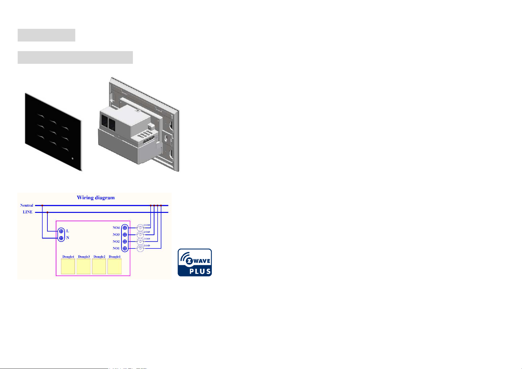
Note: The power cord must meet 1.25mm² or 16AWG or better
Introduction
All the control you want is just a few dongles away
Philio’s patent pending Smart touch in-wall Switch is the world’s first true smart electric
switch that does so much in so little in-wall space. It comes with empty relays, but the
magic happens when plug n’ play dongles are inserted into it: On/off lights, dimmers,
shutters and relays. From now on you can control everything from one elegant in-wall
switch at your home or office; or use it as a regular switch because it has such a refined
appearance.
This in-wall switch GPS-2000 is a security enabled wireless device, based on Z-Wave
Plus technology. Z-Wave PlusTM enabled devices displaying the Z-Wave PlusTM logo
can also be used with it regardless of the manufacturer, and can also be used in other
manufacturer’s Z-WaveTM enabled networks. Remote On/Off control of the switch is
possible with other manufacturer’s wireless Controller. GPS-2000 is designed to act
as a repeater. Repeaters will re-transmit the RF signal to ensure that the signal is
received by its intended destination by routing the signal around obstacles and radio
dead spots. Because GPS-2000 supports Security Command Class, it can learn with
Secured controller. Its functionality and supported command classes is identical when
included as a secure and non-secure device.
Safety Precautions and Installation
• Avoid installing the unit in storming or raining weather.
• Be sure to isolate or switch off power source before installing or
maintenance.
• Do ensure that the power supply circuit protected by a 16A circuit breaker or
suitable equivalent fuse.
• Make sure to protect each external power circuit 5A (relay dongle) by using
5A circuit breaker.
IMPORTANT
• Installation must be performed by skilled technicians who are informed about
the standards and technical requirements of the appliance and its proper
installation.
• Check your local codes as they apply to your situation. If the house wiring is
Before proceeding with the installation, TURN OFF THE POWER TO THE LIGHTING
CIRCUIT AT THE CIRCUIT BREAKER OR FUSE BOX TO AVOID ELECTRICAL
SHOCK.
1
of aluminum, consult with an electrician about proper wiring methods.
Page 2
1.
Adding to Z-WaveTM Network
In the front casing, there is an on/off button with LED indicator below which is used to
toggle switch on and off or carry out inclusion, exclusion, reset or association. When
first power is applied, its LED flashes on and off alternately and repeatedly at 0.5
second intervals. It implies that it has not been assigned a node ID and start auto
inclusion.
Auto Inclusion
The function of auto inclusion will be executed as long as the in-wall switch does not
have Node ID and just connect the switch to main power.
Note: Auto inclusion timeout is 2 minutes during which the node information of
explorer frame will be emitted once every several seconds. Unlike “inclusion” function
as shown in the table below, the execution of auto inclusion is free from pressing the
On/Off button on the Switch.
The table below lists an operation summary of basic Z-Wave functions. Please refer
to the instructions for your Z-WaveTM Certificated Primary Controller to access the
Setup function, and to include/exclude/associate devices
Function
No node ID
Inclusion
Exclusion
Description
The Z-Wave Controller does not allocate
a node ID to the Switch.
1. Put your Z-Wave controller into
inclusion mode by following the
instructions provided by the
controller manufacturer.
2. Pressing INCLUDE_BUTTON (No.5)
three times within 1.5 seconds will
enter inclusion mode.
1. Put your Z-Wave controller into
exclusion mode by following the
instructions provided by the
controller manufacturer.
Pressing INCLUDE_BUTTON
(No.5) three times within 1.5
seconds will enter exclusion mode.
LED 1.5-second on, 1.5second off
One press one flash LED
One press one flash LED
Annotation
3. Node ID has been excluded.
Reset
Association
Including a node ID allocated by Z-Wave Controller means inclusion. Excluding a node
ID allocated by Z-Wave Controller means exclusion.
Failed or success in including/excluding the node ID can be viewed from the Z-Wave
Controller.
1.
Pressing INCLUDE_BUTTON
(No.5) three times within 2 seconds
will enter inclusion mode.
2.
Within 1 second, press On/Off
button again for 5 seconds.
3.
IDs are excluded.
1. The
listening
Or If your controller requires to have
information
2. There are 4 groups for the switch
GPS-2000
Z-Wave device, so associations
be added or removed by a controller
at any time.
the
GPS-2000
frame' or NIF for associations,
pressing the On/Off button three
times within 2 seconds will cause
the
GPS-2000
is an always
send a 'node
to send its NIF.
LED 0.5s On, 0.5s Off
(Enter auto inclusion)
Use this procedure only in
the event that the primary
controller is lost or
otherwise inoperable.
LED 0.5s On, 0.5s Off
(Enter auto inclusion)
LED one press one flash
Z-Wave Supported Command Class:
• COMMAND_CLASS_ZWAVEPLUS_INFO_V2
• COMMAND_CLASS_CONFIGURATION
• COMMAND_CLASS_MANUFACTURER_SPECIFIC_V2
• COMMAND_CLASS_VERSION_V2
• COMMAND_CLASS_ASSOCIATION_GRP_INFO
• COMMAND_CLASS_POWERLEVEL
• COMMAND_CLASS_DEVICE_RESET_LOCALLY
• COMMAND_CLASS_SECURITY
2
Page 3

Overview
A
inclusion Button
A. LED indication (1-9 button).
B. RJ11 connector x 2.
C. switch or dimmer dongles (operational).
Installation and Operation
Assembly steps:
1. Open the back cover (1) and insert the dongle (figure 1)
2. Move the panel (3) upwards (Figure 2) and remove it (Figure 3)
3. Install the body (5) in the power distribution box and lock the screws (figure 4)
4. Cover the panel (3) (figure 5) and press down (figure 6)
5. Disassembly can be done in the opposite way
To start using GPS-2000 Smart touch in-wall Switch, please connect the device to
power by L and N.
You also need a PSC03/PAN27 Philio Gateway to connect
1. Connect power cable to the L and N, and you will see all button
will turn as Blue
2. Installing the companion APP
2.1 Connect your phone to Internet, login or sign up for google account or APP ID
2.2 Launch Play store or APPLE store
2.3 Search for Philio Home Mate2, then install the companion app.
2.4 Click the APP and you can use local LAN search or QR code to find
Philio Gateway
3
Page 4

2.5 Please use ID: admin / password:888888 to login the APP.
About detail of APP, please see the APP manual(click )
How to use GPS-2000
1 The functions of GPS-2000::::
1.1. GPS-2000 can install 4 Relay/Dimmer dongles and can hot plugin.
1.2. GPS-2000 can use RS485/Z-wave connect.
1.3. GPS-2000 can be use “Remote control” , Philio call it “Smart Button”
1.4. GPS-2000 each relay dongle can bear current 5A
1.5. GPS-2000 each shutter dongle can bear current 5A
1.6. GPS-2000 each dimmer dongle can bear current 0.7A
Include and Exclude::::
1. Include/Exclude: Press Central button(NO5) 1 .5 seconds until the surround LED
flash three times
2. To control Relay/Dimmer Dongle:
The default key is 1. Right Top (Button 3) / 2. Right Button (Button 9)
3. Left Bottom (Button 7) / 4. Left Top (Button 1)
3. To control Relay Dongle: You press one time, it change on/off.
4. To control Dimmer Dongle:
* To short press button, the dimmer will be last time dimmer %.
* To long press button, the % will continue change until you free the button.
The setting button mode
1. To enter setting button mode
*Enter setting mode: Press central key (Button 5), and long press right bottom button
(Button 9) until surround Blue LED will twice 3 times.
2. To config button mode with Dongle
When you success enter the config button mode, you will see the LED light
disappear one by one then turn on Blue light.
The NO1 relay/dimmer dongle the surrounding blue led will flash one time.
The NO2 relay/dimmer dongle the surrounding blue led will flash two time.
The NO3 relay/dimmer dongle the surrounding blue led will flash three time.
The NO4 relay/dimmer dongle the surrounding blue led will flash four time.
*You need finish 4 relay/dongle setting, or the setting will not be saved.
*Leaving setting mode: Press central key (Button 5) ,and long press right bottom
button (Button 9) until surround Blue LED will twice 3 times.
How to use Smart Button (Remote control)
4
Page 5

1. When you include a 9 button GPS-2000 and you will see screen like this. You
Symptom
Cause of Failure
Recommendation
The
switch
does not
1.
The Switch is not
down
1.
Check power connections
The LED illuminates, but
cannot turn ON or OFF
1. Check if the load
plugged into the
1. Set the ON/OFF switch of the
load attached to ON
the switch
Switch has its own
interference
2. Carry out association
LED keep flashing, but
Overload occurs
Remove the load attached or
10.0A
Operating Voltage
100-240VAC 50/60Hz
Max.
10A
Rated Voltage
100-240VAC 50/60Hz
Maximum Load
10A (Resistive Load)
Range
Minimum 40
M in door and 100
M in
outdoor
, line of sight
Operating
Temperature
0°C ~ 40°C
(85% humidity)
Storage
Temperature
Location
Frequency Range
916MHz (Israel)
RF power
Di
mension
P
atent pending
can collapse as 1 Button or expand as 9 buttons.
2. When you click 1 button, you will see the value will change to 105 And you also
can long press as the value will be change value 9 every second (9,18, 27, 36,
45, 54, 63, 72, 81, 90, 99)
3. Please press the icon of the button, you will see a lot of config. The most important
is “Associate”, You need to Associate the Switch and Smart Button here.
Table of connections
interface L-N AC100-240V
NO1-NO4 Control on/off
Dimming
RJ11 4P2C, for RS485 interface
Sensor Lighting Light /Dark
Temperature -10~40°C
Humidity 0-80% RH
Button Learn key Z-wave include/exclude
LED
indicator
Dongle Operational Relay / Dimmer
1-9 Key User define
1-9 Key Blue/Green
4. Firmware update over the air (OTA)
GPS-2000 is based on 500 series SoC and supports Firmware Update Command
Class, it can receives the updated firmware image sent by controller via the Z-wave
RF media. It is a helpful and convenient way to improve some function if needed.
Troubleshooting
ON/OFF switch
2. Not carry out
association
3. Same frequency
cannot control
3.Wait for a while to re-try
check max. load cannot exceed
Specification
Output Current Max.10A (Resistive Load),
Relay dongle /Curtain dongle: 5A (model: GPD-5000S/GPS-
5000L)
Dimmer dongle: 0.7A (Model: GPD-5000D)
4 independent relay or dimmer outputs
Dry contact DC5V*4
-20 C ~ 60°C
Indoor use only
868.40MHz; 869.85MHz(EU)
908.40MHz; 916.00MHz(USA/Canada)
+5dBm(EU), -5dBm(US)
interface RJ11 x 2 (4P2C) for RS485 interface
117 (L) x 87(W) x 49 (H) mm
** Specifications are subject to change and improvement without notice.
work and the LED is off
plugged into the
electrical outlet
properly
2. The Switch break
2. Don’t open up the Switch and
send it for repair.
FCC ID: 2AQO4GPS-2000
Conforms to UL STD 60730-1
Certified to CSA STD E60730-1
5
Page 6

DANGER
Danger of electrocution!
All works on the device may be performed only by a qualified and licensed
electrician. Observe national regulations.
Any works introducing changes into the configuration must be always performed with
disconnected voltage.
Choosing a Suitable Location
1. Do not locate the Module facing direct sunlight, humid or dusty place.
2. The suitable ambient temperature for the Module is 0°C~40°C.
3. Do not locate the Module where exists combustible substances or any source of
heat, e.g. fires, radiators, boiler etc.
4. After putting it into use, the body of Module will become a little bit hot of which
phenomenon is normal.
Warning:
1.Plug out to disconnect from power supply; Do not plug in line.
2. Do not exceed the max rating
Disposal
This marking indicates that this product should not be disposed with other
household wastes throughout the EU. To prevent possible harm to the
environment or human health from uncontrolled waste disposal, recycle it
responsibly to promote the sustainable reuse of material resources. To return
your used device, please use the return and collection systems or contact the
retailer where the product was purchased. They can take this product for
environmental safe recycling
This equipment has been tested and found to comply with the limits for a Class B digital
device, pursuant to Part 15 of the FCC Rules.
These limits are designed to provide reasonable protection against harmful interference in a
residential installation.
This equipment generates, uses and can radiate radio frequency energy and, if not installed
and used in accordance with the instructions, may cause harmful interference to radio
communications.
However, there is no guarantee that interference will not occur in a particular installation.
If this equipment does cause harmful interference to radio or television reception, which
can be determined by turning the equipment off and on, the user is encouraged to try to correct
the interference by one of the following measures:
• Reorient or relocate the receiving antenna.
• Increase the separation between the equipment and receiver.
• Connect the equipment into an outlet on a circuit different from that to which the receiver is
connected.
• Consult the dealer or an experienced radio/TV technician for help.
This device complies with Part 15 of the FCC Rules. Operation is subject
to the following two conditions:
(1) This device may not cause harmful interference, and
(2) This device must accept any interference received, including interference that may cause
undesired operation.
FCC Caution: Any changes or modifications not expressly approved by the party responsible
for compliance could void the user's authority to operate this equipment.
This transmitter must not be co-located or operating in conjunction with any other antenna or
transmitter.
FCC Interference Statement
6
 Loading...