

Page 1

SAFETY INFORMATION .............3
USING THE HOOD
Controls ..................................5
Wi-Fi Connect ............................ 6
Filters ....................................7
CARE AND CLEANING
Surfaces ..................................8
Lights ....................................8
INSTALLATION INSTRUCTIONS ... 9
TROUBLESHOOTING TIPS ......... 25
LIMITED WARRANTY .............. 26
ACCESSORIES ...................... 27
CONSUMER SUPPORT ............. 28
OWNER’S MANUAL
& INSTALLATION
INSTRUCTIONS
UVW8304
UVW8364
With QuietBoost™ Blower
Write the model and serial
numbers here:
Model # _________________
Serial # _________________
You can find them on a label
on the inside of the hood.
Para consultar una version en
español de este manual de
instrucciones, visite nuestro sitio de
internet GEAppliances.com.
ESPAÑOL
VENTED RANGE HOODS
GE is a trademark of the General Electric Company. Manufactured under trademark license.
49-2000708 Rev. 3 07-21 GEA
Page 2

THANK YOU FOR MAKING GE APPLIANCES A PART OF YOUR HOME.
Whether you grew up with GE Appliances, or this is your first, we’re happy to have you in the family.
We take pride in the craftsmanship, innovation and design that goes into every GE Appliances
product, and we think you will too. Among other things, registration of your appliance ensures that we
can deliver important product information and warranty details when you need them.
Register your GE appliance now online. Helpful websites and phone numbers are available in the
Consumer Support section of this Owner’s Manual. You may also mail in the pre-printed registration
card included in the packing material.
2 49-2000708 Rev. 3
Page 3

IMPORTANT SAFETY INFORMATION
READ ALL INSTRUCTIONS BEFORE USING
SAFETY INFORMATION
WARNING
ELECTRIC SHOCK OR INJURY TO PERSONS,
OBSERVE THE FOLLOWING:
A. Use this unit only in the manner intended by the
manufacturer. If you have questions, contact the
manufacturer.
B. Before servicing or cleaning unit, switch power off
at service panel and lock the service disconnecting
means to prevent power from being switched
on accidentally. When the service disconnecting
means cannot be locked, securely fasten a
prominent warning device, such as a tag, to the
service panel.
C. Do not use this unit with any solid-state speed
control device.
D. This unit must be grounded.
CAUTION
ONLY. DO NOT USE TO EXHAUST HAZARDOUS
OR EXPLOSIVE MATERIALS AND VAPORS.
CAUTION
TO PROPERLY EXHAUST AIR, BE SURE TO DUCT
AIR OUTSIDE. DO NOT VENT EXHAUST AIR INTO
SPACES WITHIN WALLS OR CEILINGS OR INTO
ATTICS, CRAWL SPACES OR GARAGES.
TO REDUCE THE RISK OF FIRE,
FOR GENERAL VENTILATING USE
TO REDUCE RISK OF FIRE AND
WARNING
TO PERSONS IN THE EVENT OF A RANGE TOP
GREASE FIRE, OBSERVE THE FOLLOWING*:
A. SMOTHER FLAMES with a close-fitting lid, cookie
sheet or metal tray, then turn off the burner. BE
CAREFUL TO PREVENT BURNS. If the flames do
not go out immediately, EVACUATE AND CALL
THE FIRE DEPARTMENT.
B. NEVER PICK UP A FLAMING PAN—You may be
burned.
C. DO NOT USE WATER, including wet dishcloths or
towels—a violent steam explosion will result.
D. Use an extinguisher ONLY if:
1. You know you have a Class ABC extinguisher,
and you already know how to operate it.
2. The fire is small and contained in the area where
it started.
3. The fire department is being called.
4. You can fight the fire with your back to an exit.
* Based on “Kitchen Fire Safety” published by NFPA.
TO REDUCE THE RISK OF INJURY
READ AND SAVE THESE INSTRUCTIONS
49-2000708 Rev. 3 3
Page 4

IMPORTANT SAFETY INFORMATION
READ ALL INSTRUCTIONS BEFORE USING
WARNING
RANGE TOP GREASE FIRE:
A. Never leave surface units unattended at high
settings. Boilovers cause smoking and greasy
spillovers that may ignite. Heat oils slowly on
medium settings.
B. Always turn hood ON when cooking at high heat or
when flambéing food (i.e. Crepes Suzette, Cherries
Jubilee, Peppercorn Beef Flambé).
C. Clean ventilating fans frequently. Grease should not
be allowed to accumulate on fan or filter.
SAFETY INFORMATION
D. Use proper pan size. Always use cookware
appropriate for the size of the surface element.
WARNING
ELECTRIC SHOCK OR INJURY TO PERSONS,
OBSERVE THE FOLLOWING:
A. Installation work and electrical wiring must be
done by qualified person(s) in accordance with all
applicable codes and standards, including fire-rated
construction.
B. Sufficient air is needed for proper combustion and
exhausting of gases through the flue (chimney) of
fuel burning equipment to prevent back drafting.
Follow the heating equipment manufacturer’s
guidelines and safety standards such as those
published by the National Fire Protection
Association (NFPA), the American Society for
Heating, Refrigeration and Air Conditioning
Engineers (ASHRAE) and the local code authorities.
TO REDUCE THE RISK OF A
TO REDUCE THE RISK OF FIRE,
C. When cutting or drilling into wall or ceiling, do not
damage electrical wiring and other hidden utilities.
D. Ducted fans must always be vented to the outdoors.
E. When applicable, install any makeup (replacement)
air system in accordance with local building
code requirements. Visit GEAppliances.com for
available makeup air solutions.
F. Turn off breaker to adjacent rooms while working.
WARNING
USE ONLY METAL DUCTWORK.
Ŷ'RQRWDWWHPSWWRUHSDLURUUHSODFHDQ\SDUWRI\RXU
hood unless it is specifically recommended in this
manual. All other servicing should be referred to a
qualified technician.
TO REDUCE THE RISK OF FIRE,
How to Remove Protective Shipping Film and Packaging Tape
Carefully grasp a corner of the protective shipping film
with your fingers and slowly peel it from the appliance
surface. Do not use any sharp items to remove the film.
Remove all of the film before using the appliance for the
first time.
To assure no damage is done to the finish of the
product, the safest way to remove the adhesive from
packaging tape on new appliances is an application of
a household liquid dishwashing detergent. Apply with a
soft cloth and allow to soak. NOTE: If surface is still not
clean, see page 8 for more cleaning options.
NOTE: The adhesive must be removed from all parts.
PROPER DISPOSAL OF YOUR APPLIANCE
Dispose of or recycle your appliance in accordance with Federal and Local Regulations. Contact your local
authorities for the environmentally safe disposal or recycling of your appliance.
READ AND SAVE THESE INSTRUCTIONS
4 49-2000708 Rev. 3
Page 5
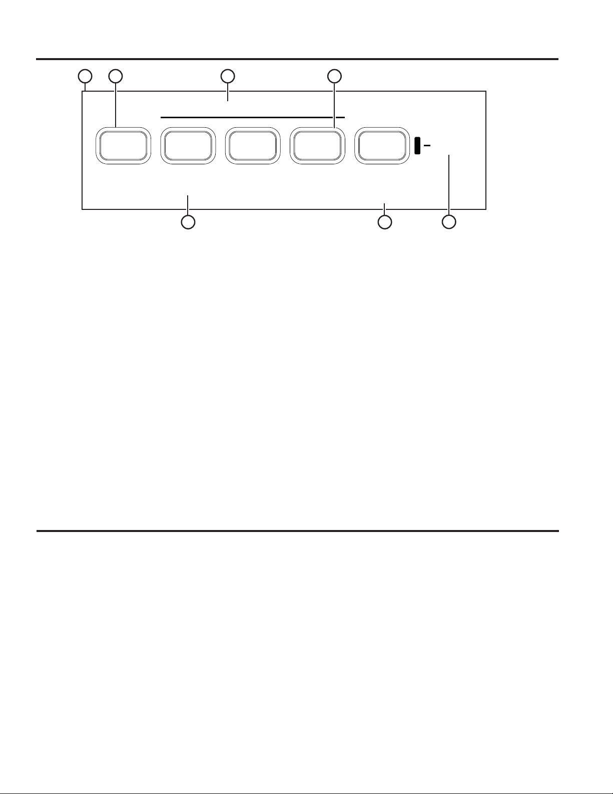
Controls
USING THE HOOD: Controls
1
2 4
3
Fan Settings
2ႇ Low Med
Delay Oႇ
Hold 3 Sec
1. Rangehood Control Panel: The control panel
is located under the front edge of the canopy. The
position and function of each control button are noted
below.
2. Fan On/Off: On/Off switch for the fan. The fan
can be operated by pressing any of the fan setting
buttons. Hold Power for 3 seconds to activate Delay
Off feature, which automatically turns the fan off after
15 minutes. Low, Med and High buttons LEDs will
rolling blink to indicate Delay Off feature is activated.
3. Fan Settings: Speed control for fan. Fan speed is
powered by QuietBoost™ Technology. This unique
technology is designed to minimize ventilation noise
and enhance motor efficiency for a peacefully-quiet,
odor-free kitchen. Press the button Low for LOW
speed, Med for MEDIUM speed, and High for HIGH
speed. Hold down the High button for 3 seconds to
activate the Boost speed that will run for 15 minutes.
High button LED will blink on/off to indicate Boost
feature is activated.
WiFi
Pairing
High Light
Boost
Hold 3 Sec
Chef Connect
To Pair
WiFi
Hold 3 Sec
57
6
4. Light: Off/On/Night Light switch for the LED lights.
Press the Light button to turn the lights on, again to
set the lights to night light setting, and again to turn
the lights off.
5. Chef Connect: This is a Bluetooth
feature for use with other compatible Chef Connect
enabled products on a cooktop or range. When the
device is paired, the default sync settings will be
activated upon receiving a command from the range
or cooktop. To change the default sync setting, refer
to the Chef Connect section.
To pair devices, hold down the Light button for 3
seconds. To turn it back off, hold the button down for
another 3 seconds. See the Chef Connect section for
more details.
®
pairing
6. IR Sensor: Remote control receiver when used
with remote control kit.
7. Wi-Fi: Hold down the Low button for 3 seconds to
initiate the Wi-Fi connection. The Wi-Fi indicator light
turns on when connected, see the Wi-Fi Connect
section for details.
Chef Connect
Chef Connect Operation Bluetooth® Connection
To pair with another device:
To start the pairing process on the hood, press and hold
the Light button for 3 seconds. The backlight for all the
icons will flash until the hood is paired with the range or
other device. If the pairing is successful, the backlights of
all buttons will flash simultaneously three times and then
turn off. The hood lights and fan default sync setting will
be activated.
It will time out after 2 minutes if the pairing is not
completed, after which the pairing sequence will need to
be restarted.
To cancel pairing:
To cancel the pairing, hold the Light button down for 3
seconds and then turn off the hood.
49-2000708 Rev. 3 5
Default Sync Settings:
The factory default setting for the light will be the brightest.
The factory default setting for the fan sync will be OFF.
The user can change the Default Sync Settings by
pressing and holding the Med button for 3 seconds.
This will enter the Default Settings Mode. Once in
this mode, the backlights for all buttons will blink on/
off indefinitely and the fan and light will switch to the
current Default Sync Setting, so the user knows what the
current default value is. At this time, set the light and fan
to the desired default levels. Once the user is satisfied
with the selection, press and hold the Power button
for 3 seconds. This will exit this mode. At that time the
backlights will stop blinking and the state of the fan and
light will change back to their prior state before entering
the Default Settings Mode.
Page 6
Wi-Fi Connect
Connecting your Wi-Fi Connect Enabled hood (on some models)
Your GE Appliances hood is designed to provide you
with two-way communication between your appliance
and smart device. By using the GE Appliances Wi-Fi
Connect features, you will be able to control essential
hood operations such as fan speed, light functions, delay
off and filter notification using your smartphone or tablet.
This device complies with part 15 of the FCC Rules.
Operation is subject to the following two conditions: (1)
This device may not cause harmful interference, and
(2) this device must accept any interference received,
including interference that may cause undesired
Operation.
What you will need
Your GE Appliances hood uses your existing home Wi-Fi
network to communicate between the appliance and
your smart device. In order to setup your GE Appliances
hood, you will need to gather some information:
1. Each GE Appliances hood has a connected appliance
information label that includes an Appliance Network
USING THE HOOD: Wi-Fi Connect
Name and Password. These are the two important
details that you will need to connect to the appliance.
The label is located on the side of the unit behind the
filters.
Connected Appliance Information
FCC ID: ZKJ-WCATA005
IC: 10229A-WCATA001
MAC ID: ************
Sample Label
2. Have your smart phone or tablet ready with the ability
to access the internet and download apps.
3. You will need to know the password of your home
Wi-Fi router. Have this password ready while you are
setting up your GE Appliances hood.
Network: ************
Password: **********
Connect your GE Appliances hood
1. On your smart phone or tablet visit
GEAppliances.com/connect to learn more about
connected appliance features and to download the
appropriate app.
2. Follow the app onscreen instructions to connect your
GE Appliances hood.
3. Once the process is complete, the indicator light
located on your GE Appliances hood display will stay
on solid and the app will confirm you are connected.
4. If the indicator light does not turn on or is blinking,
follow the instructions on the app to reconnect. If
issues continue please call 800.220.6899 and ask for
assistance regarding hood wireless connectivity.
To connect additional smart devices, repeat steps 1 and
2.
Note that any changes or modifications to the remote
enable device installed on this hood that are not
expressly approved by the manufacturer could void the
user’s authority to operate the equipment.
Enhanced Wi-Fi Features
Once your product is connected to Wi-Fi, you have
access to enhanced features via the phone app.
Delay Off Timer: This feature allows the user to adjust
delay off time from 1 minute to 15 minutes. The default
delay off time is 15 minutes.
Boost Timer: This feature allows the user to adjust the
boost time from 1 minute to 15 minutes. The default
boost time is 15 minutes
Night Light Timer: This feature allows the user to set
time for the night light to turn on and off automatically.
Grease/Charcoal Filter Notifications: This feature
sends a regular reminder to the user to clean their
grease filters, and/or to replace their charcoal filter, if the
hood is setup in recirculation mode.
6 49-2000708 Rev. 3
Page 7

Filters
Be sure the circuit breaker is off and all surfaces are cool before cleaning or servicing any part of the vent hood.
Grease Filter
The filter traps grease released by foods from cooking.
The filters must ALWAYS be in place when the hood
is in use. The grease filters are dishwasher-safe and
should be cleaned every month, or as needed.
To remove:
Pull downward on the filter lock to release the filter.
To replace:
Fit the tabs at the bottom of the filter behind the ledge of
the filter opening. Lift up the front side of the filter, push
downward on the filter lock, and push gently until the filter
is in place. Release the filter lock to secure the filter in
place.
To clean, swish the filter in hot soapy water and rinse
in clean water or wash it in the dishwasher. Do not use
abrasive cleansers.
NOTE: Some discoloration may occur to the grease filters
in the dishwasher.
Filter Lock
CARE AND CLEANING: Filters
Charcoal Filter (for recirculation installation only)
NOTE: DO NOT rinse, or put charcoal filter in an
automatic dishwasher.
The charcoal filter is NOT included with the unit.
Order charcoal filter UXCF91. It cannot be cleaned;
it must be replaced. It is recommended that the
charcoal filter be replaced every 6 months or if it is
noticeably dirty or discolored.
To reduce the risk of fire and shock, when used in
recirculation mode, use only charcoal filter UXCF91.
To inquire about purchasing replacement charcoal filters
or to find the location of a dealer nearest you, please call
our toll-free number:
National Parts Center 800.626.2002
To Install
1. Remove the grease filters. See Filters section.
2. Install the charcoal filter mounts to either side of the
motor using three screws per side.
3. Insert the tab on the charcoal filter into the triangular
slot on the mount.
4. Clip the charcoal filter in until it is locked
5. Repeat with second filter on the other side of the
motor.
6. Reattach the metal filters. See Filters section.
To Remove
1. Remove grease filters-See Filters section
2. Unclip the charcoal filter by pressing the release clip.
3. Carefully remove charcoal filter from tab.
Charcoal Filter Mount
49-2000708 Rev. 3 7
Page 8

Surfaces
Stainless Steel Surfaces (on some models)
Do not use a steel wool pad; it will scratch the surface.
To clean the stainless steel surface, use warm sudsy
water or a stainless steel cleaner or polish. Always wipe
the surface in the direction of the brush line. Follow
the cleaner instructions for cleaning the stainless steel
surface. Cleaners with oxalic acid such as Bar Keepers
Friend Soft Cleanser™ will remove surface rust,
tarnish, and small blemishes. Use only a liquid cleanser
free of grit and rub in the direction of the brush lines with
a damp soft sponge.
Lights
To change the LED lamps, schedule a service
appointment. See Consumer Support page in the front of
this manual for a list of websites and contact information.
To inquire about purchasing stainless steel appliance
cleaner or polish, or to find the location of a dealer
nearest you, please call our toll-free number:
National Parts Center
800.626.2002
GEApplianceParts.com
CARE AND CLEANING: Surfaces / Lights
8 49-2000708 Rev. 3
Page 9

INSTALLATION INSTRUCTIONS
Installation
Range Hoods
Instructions
“If you have questions, call GE Appliances at 800.GE.CARES (800.432.2737)
or visit our website at: GEAppliances.com”
BEFORE YOU BEGIN
Read these instructions completely and carefully.
Ŷ
IMPORTANT — Save these
instructions for local inspector’s use.
Ŷ
IMPORTANT — Observe all governing
codes and ordinances.
Ŷ
Note to Installer – Be sure to leave these
instructions with the Consumer.
Ŷ
Note to Consumer – Keep these instructions for
future reference.
Ŷ
Skill level – Installation of this vent hood requires
basic mechanical and electrical skills.
Ŷ
Completion time – Approximately 1 to 3 hours
Ŷ
Proper installation is the responsibility of the
installer.
Ŷ
Product failure due to improper installation is not
covered under the Warranty.
CAUTION
these vent hoods and to reduce the risk of personal
injury or damage to the product, TWO PEOPLE
ARE REQUIRED FOR PROPER INSTALLATION.
Due to the weight and size of
WARNING
ELECTRIC SHOCK OR INJURY TO PERSONS,
OBSERVE THE FOLLOWING:
A. Installation work and electrical wiring must be
done by qualified person(s) in accordance with
all applicable codes and standards, including
fire-rated construction.
B. Sufficient air is needed for proper combustion
and exhausting of gases through the flue
(chimney) of fuel burning equipment to prevent
back drafting. Follow the heating equipment
manufacturer’s guidelines and safety standards
such as those published by the National Fire
Protection Association (NFPA), the American
Society for Heating, Refrigeration and Air
Conditioning Engineers (ASHRAE) and the local
code authorities.
C. When cutting or drilling into wall or ceiling, do
not damage electrical wiring and other hidden
utilities.
D. Ducted fans must always be vented to the
outdoors.
E. Turn off breaker to adjacent rooms while
working.
WARNING
USE ONLY METAL DUCT WORK.
TO REDUCE THE RISK OF FIRE,
TO REDUCE THE RISK OF FIRE,
FOR YOUR SAFETY
WARNING
WARNING
switch power off at service panel and lock the
service disconnecting means to prevent power from
being switched on accidentally. When the service
disconnecting means cannot be locked, securely
fasten a prominent warning device, such as a tag,
to the service panel.
49-2000708 Rev. 3 9
Before beginning the installation,
at the main circuit breaker or fuse box before
installing.
Disconnect all electrical power
Page 10

Installation Preparation
PRODUCT DIMENSIONS
30” Models
Requires a 30” opening.
16-1/2"
10"
21"
30"
36” Models
Requires a 36” opening.
INSTALLATION PREPARATION
TOOLS AND MATERIALS
REQUIRED (NOT SUPPLIED)
Safety glasses
Pencil and tape measure
Phillips screwdriver with
at least 6" shank
Level
Wire cutter/stripper
Electric drill with #2 Phillips
and 1/8" and 5/16" drill bits
Aluminized
duct tape
16-1/2"
10"
21"
36"
REMOVE THE PACKAGING
CAUTION
sharp edges.
Ŷ Remove the hardware bag, literature package and
other boxed parts.
Ŷ Remove and properly discard the protective
plastic wrapping and other packaging materials.
Ŷ Consider recycling options for your appliance
packaging material.
Wear gloves to protect against
UL listed wire nuts
Strain relief for
junction box
8" round duct
Gloves
10 49-2000708 Rev. 3
Page 11
Installation Preparation
INSTALLATION PREPARATION
PLAN THE INSTALLATION
CAUTION
properly exhaust air, be sure to duct the air outside.
Do not vent exhaust air into spaces within walls or
ceilings or into attics, crawl spaces, or garages.
PARTS SUPPLIED FOR INSTALLATION
Ŷ 1 Hardware Package
Ŷ 1 Literature Package
Ŷ 1 Installation Template
PARTS NEEDED FOR INSTALLATION
Ŷ 1 Strain Relief
Ŷ 1 Wall or Roof Cap (for vented installation only)
Ŷ All Metal Ductwork
WARNING
PERSONAL INJURY HAZARD
Because of the weight and size of the rangehood
canopy. It is recommended that 2 people are used
to install the range hood. Failure to properly lift
rangehood could result in damage to the product or
personal injury.
NOTE: This rangehood can be installed as either
ducted or recirculation. In a ducted application, this
rangehood can be vented through the wall or ceiling.
When installed for recirculation, the rangehood vents
out the sides of the duct cover.
NOTE: Before making any cuts or holes for
installation, determine which venting method will be
used and carefully calculate all measurements.
To reduce risk of fire and to
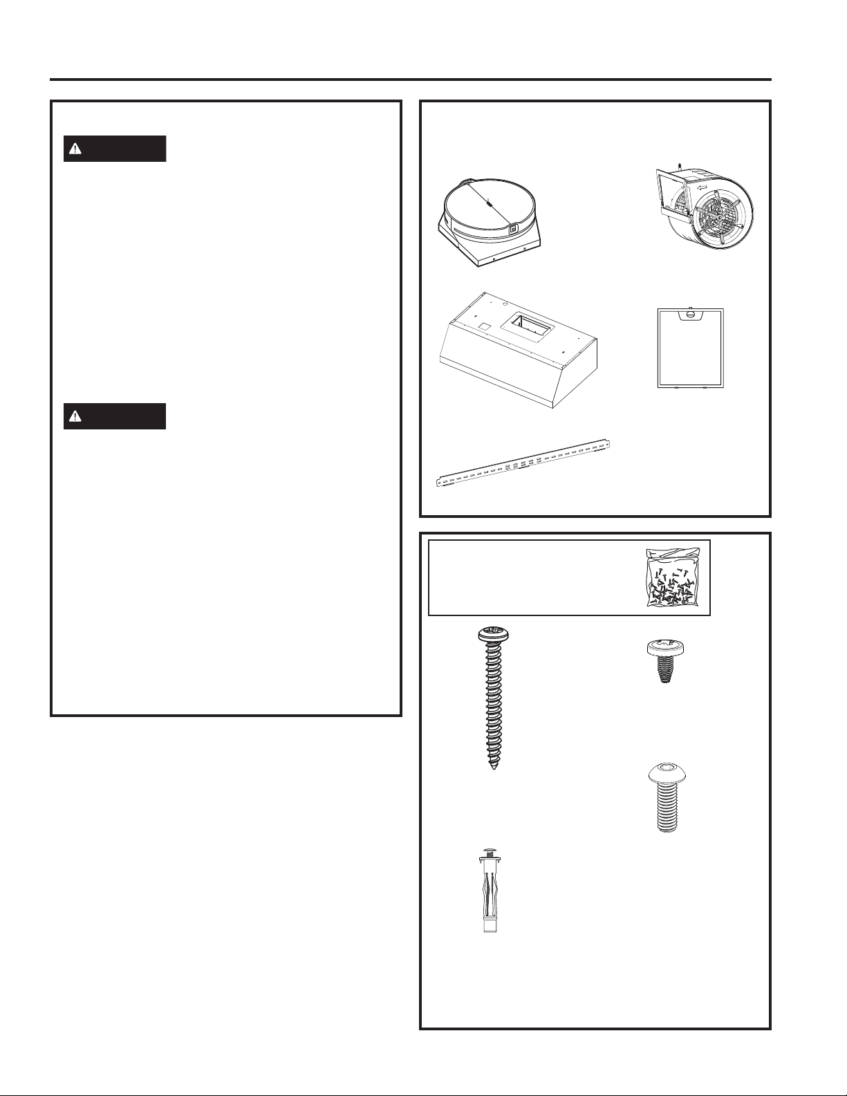
PARTS PROVIDED
Locate the parts packed with the hood.
Top Damper
Motor
Hood Body
Metal Installation Bracket
2 Grease Filters
(3 with 36" model)
HARDWARE PACKAGE
Locate and check contents.
AB
(QTY: 4) 2.9mm x 6mm
PZ screws. Used to
attach the damper
(QTY: 4) 8 x 1-3/4" AB
Screw. Used to mount the
installation bar. Use 1/8"
drill for pilot hole.
C
(QTY: 2) 3/16” dry wall
anchors with screws. Used for
hood bottom mounting screw
holes. Use 5/16” drill for pilot
hole.
49-2000708 Rev. 3 11
D
(QTY: 4) M4 screws.
Used to mount motor
Page 12
Installation Preparation
DUCT COVER REQUIREMENTS
Duct Cover Kit must be purchased separately. We
recommend that the vent hood and duct cover
(if used) be on site before final framing and wall
finishing. This will help to accurately locate studs,
ductwork, and electrical service.
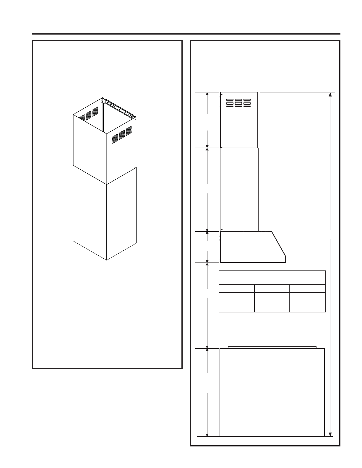
INSTALLATION PREPARATION
INSTALLATION DIMENSIONS
The hood duct covers can be adjusted for different
ceiling heights depending on the distance between
the bottom of the hood and the cooktop (distance
X). See Installation Height Table on the next page.
5" Min
25" Max
19-1/2"
Upper Duct
Cover
Lower Duct Cover
• Duct cover accessory comes with a lower and
upper duct cover and installation hardware.
• The installation hardware includes mounting
brackets to secure duct covers to the wall.
• When not recirculating, holes can be hidden by
turning the upper duct cover upside-down.
• For ceiling installations up to 10' 8", use the 10’
High Ceiling Duct Cover kit CX10DC9SPSS.
• For higher ceiling installations up to 12' 8", use the
12’ High Ceiling Duct Cover kit CX12DC9SPSS.
• See the next page for duct cover installation height
information.
10"
X
36" or
38"
Required Min & Recommended Max Ceiling
Height Examples for 10’ Duct Cover Kit (Vented)
Electric Gas
X = 24”
Min Y = 7' 6”
Max Y = 9’ 2”
X = Distance from hood to cooktop. (Varies
depending on the installation) Required 24”
minimum over electric range or 30” minimum over
gas range. The recommended maximum is 36”.
X = 30”
Min Y = 8’ 2”
Max Y = 9’ 10”
Typical Range
NOTE: 36" for typical
electric range and 38" for
gas range.
X = 36”
Min Y = 8’ 8”
Max Y = 10’ 4”
Y
12 49-2000708 Rev. 3
Page 13

Installation Preparation
INSTALLATION HEIGHT TABLE
CX10DC9SPSS CX12DC9SPSS
High Ceiling Duct Cover up to 10 ft. High Ceiling Duct Cover up to 12 ft.
Installation Over Gas Range Installation Over Electric Range Installation Over Gas Range Installation Over Electric Range
Ceiling
Height
(ft./in.)
Recirculation
Installation
Height
7' 6" 24 8' 7" 24
7' 7" 24-25 8' 8" 24-25
7' 8" 24-26 8' 9" 24-26
7' 9" 24-27 8' 10" 24-27
7' 10" 24-28 8' 11" 24 24-28
7' 11" 24 24-29 9' 0" 24-25 24-29
8' 0" 24-25 24-30 9' 1" 24-26 24-30
8' 1" 24-26 24-31 9' 2" 24-27 24-31
8' 2" 30 24-27 24-32 9' 3" 30 24-28 24-32
8' 3" 30-31 24-28 24-33 9' 4" 30-31 24-29 24-33
8' 4" 30-32 24-29 24-34 9' 5" 30-32 24-30 24-34
8' 5" 30-33 24-30 24-35 9' 6" 30-33 24-31 24-35
8' 6" 30-34 24-31
8' 7" 30 30-35 24-32 9' 8" 30-31 30-35 24-33
8' 8" 30-31
8' 9" 30-32 24-34 9' 10" 30-33 24-35
8' 10" 30-33 24-35 9' 11" 30-34
8' 11" 30-34
9' 0" 30-35 10' 1"
9' 1"
9' 2" 10' 3"
9' 3" 25-36 10' 4"
9' 4" 26-36 10' 5"
9' 5" 27-36 10' 6"
9' 6" 28-36 10' 7"
9' 7" 25-36 29-36 10' 8"
9' 8" 26-36 30-36 10' 9"
9' 9" 27-36 31-36 10' 10"
9' 10" 28-36 32-36 10' 11"
9' 11" 31-36 29-36 33-36 11' 0"
10' 0" 32-36 30-36 34-36 11' 1"
10' 1" 33-36 31-36 35-36 11' 2"
10' 2" 34-36 32-36 36 11' 3"
10' 3" 31-36 35-36 33-36 11' 4" 25-36
10' 4" 32-36 36 34-36 11' 5" 26-36
10' 5" 33-36 35-36 11' 6" 27-36
10' 6" 34-36 36 11' 7" 25-36 28-36
10' 7" 35-36 11' 8" 26-36 29-36
10' 8" 36 11' 9" 27-36 30-36
30-36
Vented
Installation
Height
(Recirculation
holes hidden)
30-36
Recirculation
Installation
Height
24-33 9' 9" 30-32
24-36
Vented
Installation
Height
(Recirculation
holes hidden)
24-36
Ceiling
Height
(ft./in.)
9' 7" 30 30-34 24-32
10' 0" 30-35
10' 2"
11' 10" 28-36 31-36
11' 11" 29-36 32-36
12' 0" 31-36 30-36 33-36
12' 1" 32-36 31-36 34-36
12' 2" 33-36 32-36 35-36
12' 3" 31-36 34-36 33-36 36
12' 4" 32-36 35-36 34-36
12' 5" 33-36 36 35-36
12' 6" 34-36 36
12' 7" 35-36
12' 8" 36
Recirculation
Installation
Height
30-36
Vented
Installation
Height
(Recirculation
holes hidden)
30-36
Recirculation
Installation
Height
24-34
24-36
Vented
Installation Height
(Recirculation
holes hidden)
24-36
INSTALLATION PREPARATION
49-2000708 Rev. 3 13
Page 14
Installation Preparation
ADVANCE PLANNING
Duct Install Planning
Ŷ This hood is designed to be vented vertically through
the ceiling with a 8” round duct or backwall using an
90º elbow and 8” round duct.
Ŷ Use metal ductwork only.
Ŷ Plan the route for venting exhaust to the outdoors.
To maximize the ventilation performance of the vent
system:
1. Minimize the duct run length and number of
transitions and elbows.
2. Maintain a constant duct size.
3. Seal all joints with duct tape to prevent any leaks.
NOTE: Flexible vent is not recommended. Flexible
vent creates back pressure and air turbulence that
greatly reduces performance.
Ŷ Maximum equivalent duct length for 100 CFM: 150
INSTALLATION PREPARATION
foot for vent hoods.
Ŷ Install a wall cap or roof cap with damper at the
exterior opening. Purchase the wall or roof cap and
any transition and length of duct needed in advance.
Ŷ When applicable, install any makeup (replacement)
air system in accordance with local building code
requirements. Use makeup air kit JXMUA8.
Recirculation Install Planning
A recirculation duct and charcoal filter are necessary
for recirculation installation and must be purchased
separately.
Power Supply Planning
The location of the power supply connection is called
out in the section, House Wiring Location
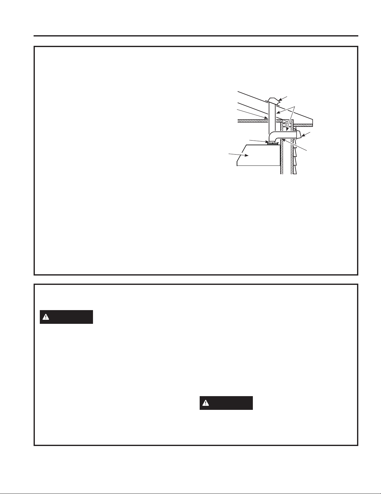
Vent system can terminate either through the roof
RUWKHZDOO7RYHQWWKURXJKDZDOODHOERZLV
needed and installed immediately above the hood.
Roof Cap
Add Insulation
and/or Caulk
Add tape to joint
Hood
Round Duct
Wall Cap
Add Insulation
and/or Caulk
POWER SUPPLY
IMPORTANT – (Please read carefully)
WARNING
FOR PERSONAL SAFETY, THIS APPLIANCE MUST
BE PROPERLY GROUNDED.
Remove house fuse or open circuit breaker before
beginning installation.
Do not use an extension cord or adapter plug with
this appliance. Follow National Electrical Codes or
prevailing local codes and ordinances.
Electrical supply
These vent hoods must be supplied with 120V, 60Hz,
and connected to a properly grounded branch circuit,
and protected by a 15 or 20 amp circuit breaker or
time delay fuse.
Ŷ Wiring must be 2 wire with ground.
Ŷ If the electrical supply does not meet the above
requirements, call a licensed electrician before
proceeding.
Ŷ Route house wiring as close to the installation
location as possible in the ceiling or wall.
Ŷ Connect the wiring to the house wiring in
accordance with local codes.
Grounding instructions
The grounding conductor must be connected to
a ground metal, permanent wiring system, or an
equipment-grounding terminal or lead on the hood.
WARNING
equipment-grounding conductor can result in a risk
of electric shock. Check with a qualified electrician or
service representative if you are in doubt whether the
appliance is properly grounded.
The improper connection of the
14 49-2000708 Rev. 3
Page 15
Installation Preparation
NEW CONSTRUCTION, PRE-PLANNING, OR REMODELING
NOTE: For existing construction, skip to the section below.
Ŷ For ducted installation through the top, the 8"
diameter hole for the duct in the ceiling must be
centered 6-1/4" away from the finished rear wall in
the installation space
Ŷ The hood junction box knockout is located 10-1/2" to
the left from center of the hood. Ensure enough wire
length is available to make electrical connection.
INSTALLATION PREPARATION
6-1/4”
DETERMINE HOOD, DUCTWORK AND WIRING LOCATIONS
• This hood can be installed onto the wall or
underneath the soffit or cabinet.
• For installing the hood to soffit or cabinet, refer to
page 18 for alternate mounting method.”
• A wall mounting template is included with the product
for ease of installation. Follow the instructions below
if the template is not being used.
• Measure desired distance from the bottom of the hood
to the cooking surface, 24" minimum over electric
range or 30" minimum over gas range, and 36"
recommended maximum.
• Use a level to draw a horizontal line indicating the
bottom of the hood.
• Use a level to draw the cooktop or range centerline
location.
• Measure 9” up from the horizontal line for the bottom
of the hood. Draw another horizontal line to indicate
the bottom of the installation bar.
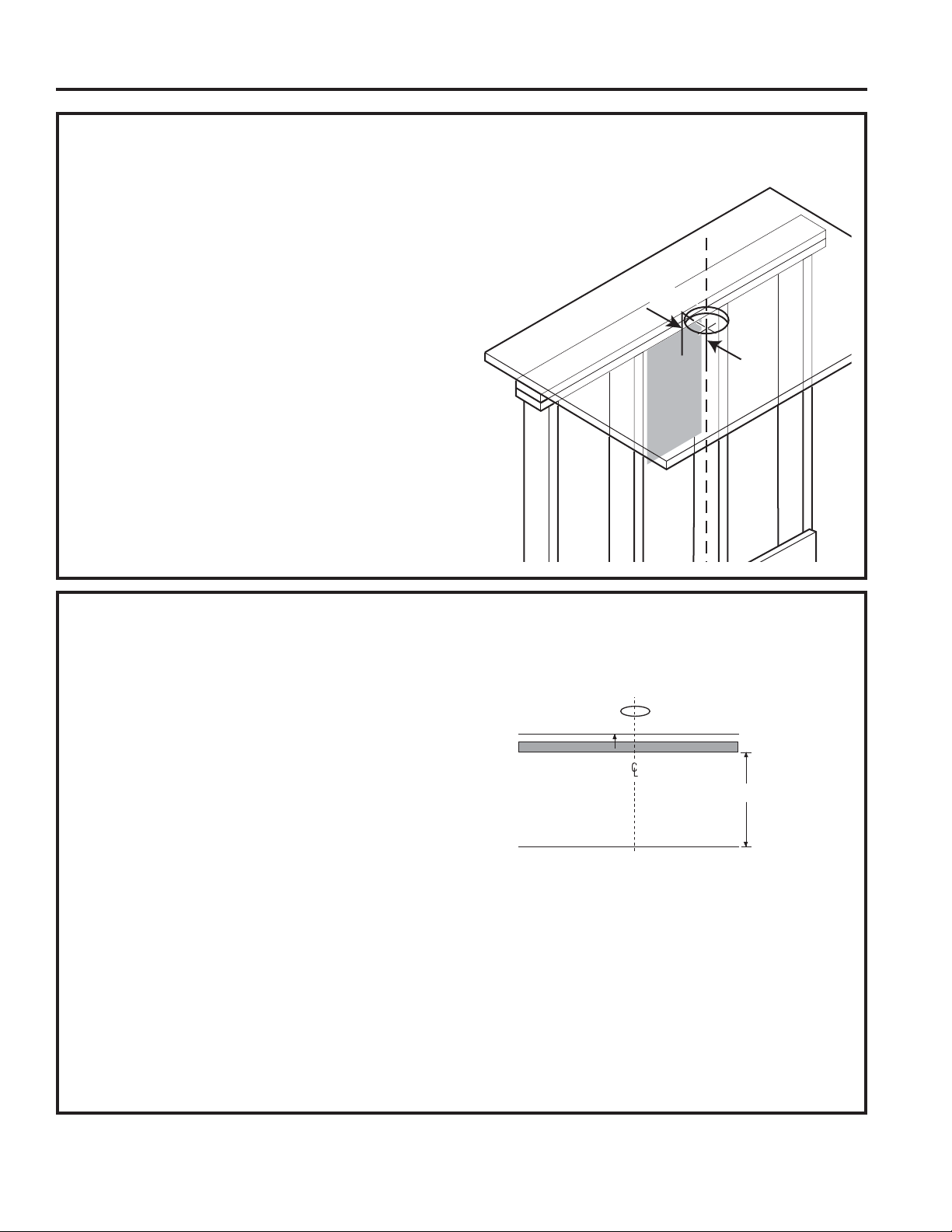
For Vertical (Straight Up) Ducting:
• If venting out the ceiling, extend the centerline
forward on the ceiling.
- Measure 6-1/4" from drywall to mark center point
for an 8" diameter duct hole on the ceiling.
- Cut an 8" dia. duct hole on the ceiling
Venting Through a Soffit or Cabinet:
• Follow the same procedure for vertical (straight-up)
Top of Hood
Bottom of Hood
ducting through the top of the soffit or cabinet.
For Ducting Through Rear Wall:
NOTE: In order to vent through the rear wall, a 90º
elbow is needed and installed above the hood damper.
• Measure the height from the top of the hood to the
center of the elbow.
• Draw a horizontal line on the wall intersecting the
centerline.
• Cut an 8" diameter hole at the intersection point for
ducting.
8" Round
9”
49-2000708 Rev. 3 15
Page 16

Installation Preparation
DETERMINE HOOD, DUCTWORK AND WIRING LOCATIONS (Cont.)
House Wiring Location:
• The junction box is located inside the hood body
on the left side. See Illustrations for hood knockout
locations.
House wiring may enter the junction box from the rear
or the top of the hood at the right side.
To route house wiring through the ceiling,soffit, or
cabinet:
• Cut a hole approximately 1-1/4" dia., forward on
the ceiling at a distance 9-3/4" to the left of the
centerline.
To route house wiring through the wall:
• Measure 7-3/4” from the bottom of the hood. and
mark location.
• Cut a hole approximately 1-1/4” dia., at the marked
location at a distance 9-3/4" to the left of the
centerline.
• Remove top or rear knockout depending on your
INSTALLATION PREPARATION
installation.
1-1/4"
Rear View
9-3/4"
Top View
9-3/4"
7-3/4"
16 49-2000708 Rev. 3
Page 17

Installation Instructions
1
INSTALL HOOD SUPPORT
IMPORTANT: Framing must be capable of
supporting 100 lbs.
• Locate at least 2 vertical studs for the installation
bar by tapping drywall with a hammer or use a
stud finder.
• Level the installation bar and center left to right
above the marked line. Hold bar against the wall.
Installation Bar
9”
24” minimum over electric range
or cooktop, or 30” minimum over
gas range or cooktop, and 36”
recommended maximum.
Centerline of
Installation Space
1
INSTALL HOOD SUPPORT (cont)
• Install wall anchors (C) by tapping the anchors with
a hammer to seat the teeth of the flanges into the
wall. This keeps anchor from rotating.
• Drive the anchor screws until the barrels crimp
against the inside of the wall.
• Remove the screws from the wall anchors before
installing the hood.
2
INSTALL DAMPER
IMPORTANT: Remove shipping tape from damper
and check that the damper moves freely.
• Install the damper to the hood body using screws
(B) from the
top of the
hood, as
shown in
image below.
• Use duct tape
to seal the
connection.
INSTALLATION INSTRUCTIONS
• Drill 1/8” pilot holes at the 2 vertical stud locations
through holes in the installation bracket. Secure
the installation bar with supplied screws (A) as
shown above.
Drill Bottom Mounting Hole Locations:
• Hang hood on installation bar or use the table
below to mark the screw hole locations. NOTE: if
installing to the soffit or cabinet, push hood flush
to the soffit or cabinet before marking screw hole
locations.
• Remove the hood and drill 5/16” clearance holes
at marked locations “A” and “B”.
Centerline of
Installation Space
A
B
Bottom of Hood
30” Model 8-3/4”
36” Model 14”
“A” “B”
1-5/8”
3
INSTALL HOOD ONTO WALL
• Pull house wiring through knockout at the back or
top of the hood.
• Lift the hood and place over the hooks on the
installation bar. Allow the hood to slide down into
position.
• Check to be sure the hood is level and centered.
• Tighten wall anchor screws (C) to finish hood body
installation to the wall.
• Remove cover from junction box inside the hood.
24” minimum over
electric range or
cooktop, or 30”
minimum over
gas range or
cooktop, and 36”
recommended
maximum.
Centerline of
Installation Space
49-2000708 Rev. 3 17
Page 18

Installation Instructions
4
(Alternate Mounting Method) INSTALL HOOD TO SOFFIT OR CABINET
SKIP THIS STEP IF USING WALL MOUNTING
METHOD
IMPORTANT: Soffit or cabinet framing must be
capable of supporting 100 lbs.
When necessary the hood may be installed so that it is
supported by the soffit or cabinet.
• The soffit should be constructed with 2"x4"s.
• Use a level to draw the cooktop or range center line.
• Continue the centerline forward on the bottom of the
soffit.
• Install horizontal wood supports between the 2"x4",
at distance A to the left and right, as per the table
below.
INSTALLATION INSTRUCTIONS
B
A
Centerline to
Center of Stud
30” Models 8-3/4"
36” Models 14"
• Drill two 1/8” pilot holes at a distance of 10” from the
back wall in the horizontal wood supports. This is the
vertical distance between mounting keyholes and
back wall as shown in Figure C.
• Drill two more 1/8” pilot holes at a distance of 2-3/4”
from the back wall in the horizontal wood supports.
This is the vertical distance between mounting screw
holes and back wall as shown in Figure C.
• For top venting, allow minimum opening (Dim. B) to
accommodate damper in soffit or cabinet.
“A”
A
“B”
Opening for
Ductwork
8-3/8" x 11-1/4"
Back Wall
2-3/4"
10"
A
Keyholes
for Soffit
or Cabinet
Mounting
Figure C
• Drive mounting Screws (A) into the studs until they
protrude 1/4". This 1/4" gap will provide clearance to
engage the keyhole slots in the top of the hood.
• The hood must also be secured to the back wall.
Follow instructions on page 17, "Drill Bottom
Mounting Hole Locations", for installation to the
back wall.
• Follow instructions on page 16 “House Wiring
Locations” for wiring setup.
• Lift hood onto mounting screws. Slide back against
the rear wall.
• Pull house wiring through the knockout at the rear or
top of the hood.
• Tighten mounting screws (A).
• Once the hood is secured to the soffit or cabinet,
drive screws (C) to secure the hood to the back wall.
Soffit or Cabinet
1/4” Gap
Engage Keyhole Slots
and Push Back at Wall
Back
Wall
18 49-2000708 Rev. 3
Page 19

Installation Instructions
INSTALLATION INSTRUCTIONS
5
INSTALL MOTOR
1. Align the motor exhaust with the top damper as
shown in figure below.
2. Secure the motor to motor mounting plate using
screws (D).
Connector
Location
Motor
Mounting Plate
6
CONNECT ELECTRICAL
Verify that power is tured off at the source.
WARNING
a ground wire, a ground must be provided by the
installer. When house wiring is aluminum, be sure
to use UL approved anti-oxidant compound and
aluminum-to-copper connections.
• Remove junction box cover.
• Pull the house wiring through the knockout at the
top or back of the hood and secure with the strain
relief.
If house wiring is not 2-wire with
3. Plug the motor connector into the mating
connector on top of the control housing.
• Use UL listed wire nuts to connect incoming white
to white, and black to black wires.
• Loosen the green grounding screw (with grounding
bracket) in the junction box. Loop solid copper
house wire clockwise around the green grounding
screw and above the bracket. Firmly tighten the
screw over the loop.
Grounding
Bracket
Green
Grounding
Screw
• Replace junction box cover and ensure wires are
not pinched.
NOTE:
For corded installation: Use only with rangehood
cord-connection kits that have been investigated
and found acceptable for use with this model
rangehood.
49-2000708 Rev. 3 19
Page 20

Installation Instructions
7
CONNECT DUCTWORK
A. Vented Installation
• Connect the house ducting to the top damper as
shown in image below.
• Seal all connections with duct tape.
House Ducting
INSTALLATION INSTRUCTIONS
B. Recirculation (non-vented) Installation
NOTE: A recirculation duct (WB34X30519), and
Charcoal Filter (UXCF91), are not included with the
hood and are necessary for recirculation installation.
1. Attach the recirculation duct to the duct cover
mounting bracket with screws provided.
2. Connect the ducting from the exhaust outlet on the
hood to the recirculation duct. Use duct tape to seal
the connections.
Ceiling
Recirculation Duct
Duct Cover
Mounting Bracket
CAUTION
the transition to ductwork connection. Doing so will
prevent proper damper operations. Seal connection
with tape only.
Do not use sheet metal screws at
Use tape
(Do not use screws.)
20 49-2000708 Rev. 3
Page 21

Installation Instructions
INSTALLATION INSTRUCTIONS
8
INSTALL DUCT COVERS
• Duct Cover Accessories are available
at GEApplianceparts.com or by calling
877.959.8688. See Accessories on page 27.
• Follow instructions included with the duct cover
accessory to install duct covers.
9
INSTALL FILTERS
• Follow instructions on page 7 “Filters” to install or
remove filters.
Filter Lock
49-2000708 Rev. 3 21
Page 22
Installation Instructions
MAKE UP AIR TECHNOLOGY
This operation must be performed by a qualified technician or installer.
Note to Installers and Inspectors : This product comes equipped with a simple installation feature that limits
maximum CFM levels in order to comply with certain local codes or regulations. This installation method may not
be necessary for all installations, please refer to your codes for further guidelines.
CAUTION
Hood must be disconnected from main power prior to performing the conversion instructions
listed below. Failure to do so could result in personal injury or damage to the product.
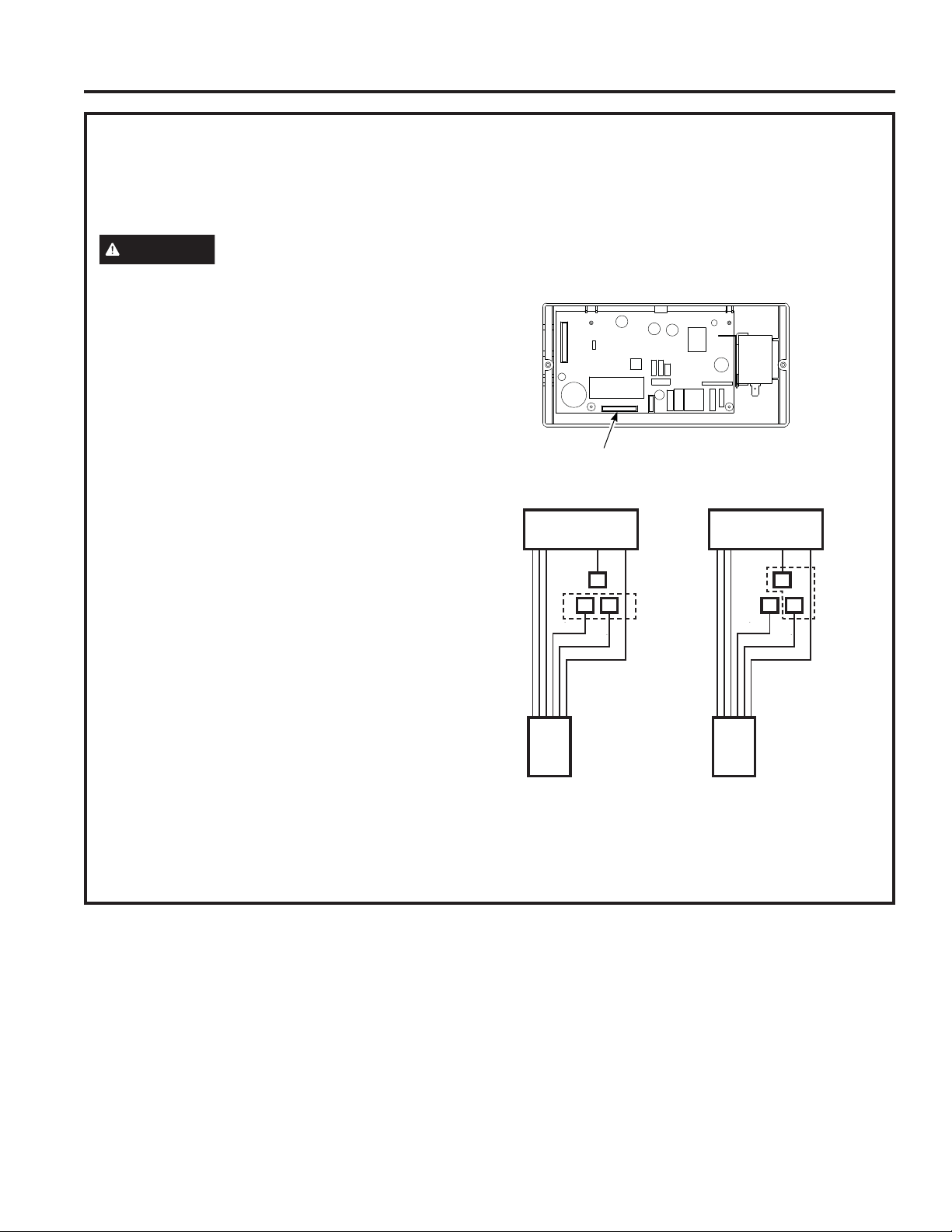
To modify unit (if needed for local codesl):
390CFM
By design, the maximum blower speed is greater than
400 CFM. For local codes requiring reduced CFM,
modify the wiring as described below:
1. Remove the grease filters.
2. Disconnect all the harnesses from the top control
box located on right side of motor.
Motor Harness Connector
3. Loosen the screws on top of control box and slide
out to remove it from the hood.
INSTALLATION INSTRUCTIONS
4. Uninstall the control box cover.
5. For a maximum of 390 CFM with 4 speeds (Low,
Medium, High and Boost):
Red
i. Disconnect connectors of the BROWN wire.
ii. Remove the cap attached to the connector of the
RED wire.
Brown
Blue
Brown
Red
iii. Connect the mating connector of the BROWN
wire and the RED wire.
iv. Attach the cap to the open BROWN wire
connector.
6. Install the control box and secure it to bracket in the
Motor Harness
hood using the two screws.
7. Connect all harnesses on top of the control box.
8. Reinstall the Grease filters.
Factory Installed
Wiring Setup
Note to Inspectors: To verify this product installation,
check motor wiring connections as described above.
Red
Brown
Blue
Brown
Red
Motor Harness
Max 390 CFM Boost
Wiring Setup
22 49-2000708 Rev. 3
Page 23

Notes
49-2000708 Rev. 3 23
Page 24

Notes
24 49-2000708 Rev. 3
Page 25

Troubleshooting Tips ... Before you call for service
Save time and money! Review the charts on the following pages first and you may not need to call for service.
Problem Possible Cause What To Do
Fan/Light does not
operate when button is
turned ON
Loud or abnormal
airflow noise
Fan fails to circulate
air or moves air slower
than normal and/or
fan is making loud or
abnormal airflow noise
Fan keeps going off
and on
Hood will not work
remotely
A house fuse may be blown or a circuit
breaker tripped.
Wrong duct size used in installation. This hood requires 8” ducting to perform optimally.
Obstructions in duct work. Make sure nothing is blocking the vent. Make sure
Damper blade on wall or roof cap may
not be open.
Metal grease filter and charcoal filter (if
present) may be dirty.
The motor is probably overheating and
turning itself off. This can be harmful to
the motor.
Router issues, no wireless signal, etc. For assistance with hood wireless network connectivity,
Hood is not connected.
Replace fuse or reset circuit breaker.
Using smaller duct pipe will cause reduced venting.
Minimize the duct run length and number of transitions
and elbows. GE Appliances service technicians cannot
correct this issue if installed improperly.
your wall or roof cap has a blade or door.
Make sure damper swings freely. Damper blades may
flip over and will not fully open when this happens.
Adjust to original position.
Clean the metal grease filter and replace charcoal filter
(if present). See Care and Cleaning of the Vent Hood.
Check to be sure the filters are clean. If off and on
cycling continues, call for service.
please call 800.220.6899.
TROUBLESHOOTING TIPS
49-2000708 Rev. 3 25
Page 26
GE Appliances Vented Range Hood Warranty
GEAppliances.com
All warranty service is provided by our Factory Service Centers, or an authorized Customer Care® technician. To schedule
service online, visit us at www.geappliances.com/service_and_support/, or call GE Appliances at 800.GE.CARES
(800.432.2737). Please have your serial number and your model number available when calling for service.
Servicing your appliance may require the use of the onboard data port for diagnostics. This gives a GE Appliances factory
service technician the ability to quickly diagnose any issues with your appliance and helps GE Appliances improve its
products by providing GE Appliances with information on your appliance. If you do not want your appliance data to be
sent to GE Appliances, please advise your technician not to submit the data to GE Appliances at the time of service.
For the period of GE Appliances will replace
One year
From the date
of the original
purchase
Any part of the cooking product which fails due to a defect in materials or workmanship.
During this limited one-year warranty, GE Appliances will provide, free of charge, all labor
and related service costs to replace the defective part.
LIMITED WARRANTY
What GE Appliances will not cover:
Ŷ Service trips to your home to teach you how to use
the product.
Ŷ Improper installation, delivery, or maintenance.
Ŷ Failure of the product if it is abused, misused,
modified, or used for other than the intended purpose
or used commercially.
Ŷ Replacement of house fuses or resetting of circuit
breakers.
Ŷ Damage to the product caused by accident, fire,
floods, or acts of God.
Ŷ Damage to finish, such as surface rust, tarnish, or small
blemishes not reported within 48 hours of delivery.
Ŷ Incidental or consequential damage caused by
possible defects with this appliance.
Ŷ Damage caused after delivery.
Ŷ Product not accessible to provide required service.
Ŷ Service to repair or replace light bulbs, except for LED
lamps.
EXCLUSION OF IMPLIED WARRANTIES
Your sole and exclusive remedy is product repair as provided in this Limited Warranty. Any implied warranties,
including the implied warranties of merchantability or fitness for a particular purpose, are limited to one year or
the shortest period allowed by law.
This limited warranty is extended to the original purchaser and any succeeding owner for products purchased for home
use within the USA. If the product is located in an area where service by a GE Appliances Authorized Servicer is not
available, you may be responsible for a trip charge or you may be required to bring the product to an Authorized GE
Appliances Service location for service. In Alaska, the limited warranty excludes the cost of shipping or service calls to
your home.
Some states do not allow the exclusion or limitation of incidental or consequential damages. This limited warranty
gives you specific legal rights, and you may also have other rights which vary from state to state. To know what your
legal rights are, consult your local or state consumer affairs office or your state’s Attorney General.
Warrantor: GE Appliances, a Haier company
Louisville, KY 40225
Extended Warranties: Purchase a GE Appliances extended warranty and learn about special discounts that are
available while your warranty is still in effect. You can purchase it online anytime at
Staple your receipt here. Proof of the original purchase
date is needed to obtain service under the warranty.
or call 800.626.2224 during normal business hours. GE Appliances Service will still be there after your warranty expires.
geappliances.com/extended-warranty
26 49-2000708 Rev. 3
Page 27

Accessories
Looking For Something More?
GE Appliances offers a variety of accessories to
improve your cooking and maintenance experiences!
Refer to the Consumer Support page for phone numbers
and website information.
The following products and more are available:
Parts
Grease filters
Duct Covers
Charcoal Filters
Recirculation Kit
Remote Control
15” cabinet filler panel
Power Cord kit
Cleaning Supplies
CitruShine™ Stainless Steel Wipes
Stainless Steel Appliance Cleaner
Bar Keepers Friend Soft Cleanser™
ACCESSORIES
49-2000708 Rev. 3 27
Page 28
Consumer Support
GE Appliances Website
Have a question or need assistance with your appliance? Try the GE Appliances Website 24 hours a day, any day
of the year! You can also shop for more great GE Appliances products and take advantage of all our on-line support
services designed for your convenience. In the US: GEAppliances.com
Register Your Appliance
Register your new appliance on-line at your convenience! Timely product registration will allow for enhanced
communication and prompt service under the terms of your warranty, should the need arise. You may also mail in
the pre-printed registration card included in the packing material. In the US: GEAppliances.com/register
Schedule Service
Expert GE Appliances repair service is only one step away from your door. Get on-line and schedule your service at
your convenience any day of the year. In the US: GEAppliances.com/ge/service-and-support/service.htm
CONSUMER SUPPORT
or call 800.432.2737 during normal business hours.
Extended Warranties
Purchase a GE Appliances extended warranty and learn about special discounts that are available while your
warranty is still in effect. You can purchase it on-line anytime. GE Appliances Services will still be there after your
warranty expires. In the US: GEAppliances.com/ge/service-and-support/shop-for-extended-service-plans.htm
or call 800.626.2224 during normal business hours.
Remote Connectivity
For assistance with wireless network connectivity (for models with remote enable),
visit our website at GEAppliances.com/ge/connected-appliances/ or call 800.220.6899 in the US.
Parts and Accessories
Individuals qualified to service their own appliances can have parts or accessories sent directly to their homes
(VISA, MasterCard and Discover cards are accepted). Order on-line today 24 hours every day.
In the US: GEApplianceparts.com or by phone at 877.959.8688 during normal business hours.
Instructions contained in this manual cover procedures to be performed by any user. Other servicing
generally should be referred to qualified service personnel. Caution must be exercised, since improper
servicing may cause unsafe operation.
Contact Us
If you are not satisfied with the service you receive from GE Appliances, contact us on our Website with all the
details including your phone number, or write to:
In the US: General Manager, Customer Relations | GE Appliances, Appliance Park | Louisville, KY 40225
GEAppliances.com/ge/service-and-support/contact.htm
Printed in Mexico
28 49-2000708 Rev. 3
Page 29

INFORMACIÓN DE SEGURIDAD ....3
USO DE LA CAMPANA
Controles .................................5
Conexión Wi-Fi ............................6
Filtros ....................................7
CUIDADO Y LIMPIEZA
Superficies ................................8
Luces ....................................8
INSTRUCCIONES
DE INSTALACIÓN
CONSEJOS PARA LA SOLUCIÓN
DE PROBLEMAS
GARANTÍA LIMITADA ..............24
ACCESORIOS ........................25
.....................9
...................23
MANUAL DEL
PROPIETARIO Y
INSTALACIÓN
UVW8304
UVW8364
Con Extractor QuietBoost™
VENTILACIÓN
SOPORTE PARA
EL CONSUMIDOR ..................26
Escriba los números de modelo y
de serie aquí:
Nº de Modelo ____________
CAMPANAS DE COCINA CON
GE es una marca registrada de General Electric Company. Fabricado bajo licencia de marca.
Nº de Serie ______________
Los puede encontrar en una etiqueta
en la pared interna de la campana.
49-2000708 Rev. 3 07-21 GEA
Page 30

GRACIAS POR HACER QUE GE APPLIANCES SEA PARTE DE SU HOGAR.
Ya sea que haya crecido usando GE Appliances, o que ésta es su primera vez, nos complace
tenerlo en la familia.
Sentimos orgullo por el nivel de arte, innovación y diseño de cada uno de los electrodomésticos de
GE Appliances, y creemos que usted también. Entre otras cosas, el registro de su electrodoméstico
asegura que podamos entregarle información importante del producto y detalles de la garantía
cuando los necesite.
Registre su electrodoméstico GE ahora a través de Internet. Sitios Web y números telefónicos útiles
están disponibles en la sección de Soporte para el Consumidor de este Manual del Propietario.
También puede enviar una carta en la tarjeta de inscripción preimpresa que se incluye con
el material embalado.
2 49-2000708 Rev. 3
Page 31

INFORMACIÓN IMPORTANTE DE SEGURIDAD
LEA TODAS LAS INSTRUCCIONES ANTES DE USAR
INFORMACIÓN DE SEGURIDAD
ADVERTENCIA
DE INCENDIO, DESCARGA ELÉCTRICA O LESIONES A
PERSONAS, CUMPLA CON LOS SIGUIENTES PUNTOS:
A. Utilice esta unidad sólo de la manera concebida por el
fabricante. Si tiene alguna pregunta, comuníquese con el
fabricante.
B. Antes de realizar reparaciones o limpiar la unidad,
desconecte la energía del panel de servicio y bloquee los
medios de desconexión para evitar el accionamiento de
la energía de manera accidental. Cuando los medios de
desconexión de servicio no pueden bloquearse, coloque
sobre el panel de servicio un dispositivo de advertencia
bien visible, como una etiqueta.
C. No utilice esta unidad con ningún dispositivo de control
de velocidad de estado sólido.
D. Esta unidad debe estar conectada a tierra.
PRECAUCIÓN
VENTILACIÓN GENERAL. NO LO UTILICE PARA
ELIMINAR MATERIALES Y VAPORES PELIGROSOS O
EXPLOSIVOS.
PRECAUCIÓN
DE INCENDIO Y PARA ELIMINAR EL AIRE DE ESCAPE
CORRECTAMENTE, ASEGÚRESE DE DIRIGIR EL AIRE
DEL CONDUCTO HACIA EL EXTERIOR. NO VENTILE EL
AIRE DE ESCAPE EN ESPACIOS DENTRO DE PAREDES
O CIELORRASOS O EN ÁTICOS, HUECOS SANITARIOS
O GARAJES.
PARA REDUCIR EL RIESGO
SÓLO PARA USO DE
PARA REDUCIR EL RIESGO
ADVERTENCIA
LESIONES A PERSONAS EN CASO DE UN INCENDIO
DE GRASA SOBRE UNA ESTUFA, CUMPLA CON LOS
SIGUIENTES PUNTOS*:
A. APAGUE LAS LLAMAS con una tapa que ajuste bien,
una plancha para galletas o una bandeja de metal, y
luego apague el quemador. TENGA MUCHO CUIDADO
A FIN DE EVITAR QUEMADURAS. Si las llamas no
se apagan de inmediato, SALGA DE LA VIVIENDA Y
LLAME AL DEPARTAMENTO DE BOMBEROS.
B. NUNCA LEVANTE UNA SARTÉN EN LLAMAS—
Usted puede quemarse.
C. NO UTILICE AGUA, incluyendo repasadores o toallas
húmedos—se provocará una violenta explosión de vapor.
D. Utilice un extintor SÓLO si:
1. Usted sabe que cuenta con un extintor Clase ABC y
ya sabe cómo utilizarlo.
2. El incendio es pequeño y se contuvo en el área donde
comenzó.
3. Se está llamando al departamento de bomberos.
4. Usted puede combatir el incendio con su espalda
dirigida hacia una salida.
* Basado en “Kitchen Fire Safety” publicado por NFPA.
PARA REDUCIR EL RIESGO DE
LEA Y GUARDE ESTAS INSTRUCCIONES
49-2000708 Rev. 3 3
Page 32

INFORMACIÓN IMPORTANTE DE SEGURIDAD
LEA TODAS LAS INSTRUCCIONES ANTES DE USAR
ADVERTENCIA
UN INCENDIO DE GRASA SOBRE UNA ESTUFA:
A. Nunca deje unidades de superficie desatendidas en
configuraciones de calor elevadas. Los alimentos que
hierven y se derraman provocan humo y derrames
grasosos que pueden prenderse fuego. Caliente los
aceites lentamente en configuraciones bajas o medias.
B. Siempre encienda el sistema de ventilación cuando
cocine con configuraciones de calor elevadas o cuando
flambee alimentos (por ej., Crepes Suzette, cerezas
Jubilee, carne flambeada a la pimienta en grano).
C. Limpie los ventiladores con frecuencia. No debe
permitirse la acumulación de grasa en el ventilador o en
el filtro.
D. Utilice el tamaño de recipiente adecuado. Siempre utilice
recipientes de cocción apropiados para el tamaño del
elemento de superficie.
ADVERTENCIA
RIESGO DE INCENDIOS, DESCARGAS ELÉCTRICAS
INFORMACIÓN DE SEGURIDAD
O LESIONES PERSONALES, CUMPLA CON LO
SIGUIENTE:
A. El trabajo de instalación y el cableado eléctrico deben
ser realizados por una persona(s) calificada de acuerdo
con todos los códigos y estándares aplicables, incluyendo
construcciones resistentes al fuego.
B. Es necesario contar con suficiente cantidad de aire
para una combustión y salida de gases adecuadas a
través del conducto (chimenea) del equipo de consumo
de combustible, a fin de evitar ráfagas de aire. Siga las
pautas del fabricante del equipo de calefacción y los
estándares de seguridad, tales como aquellos publicados
por la Asociación Nacional de Protección contra
Incendios (National Fire Protection Association, NFPA), la
Sociedad Estadounidense para la Calefacción (American
Society for Heating), los Ingenieros de Refrigeración
y Acondicionadores de Aire (Refrigeration and Air
Conditioning Engineers, ASHRAE) y las autoridades de
los códigos locales.
PARA REDUCIR EL RIESGO DE
A FIN DE REDUCIR EL
C. Al cortar o perforar una pared o un cielorraso, no dañe el
D. Los ventiladores con conducto siempre deben contar con
E. Cuando corresponda, instale un sistema de reposición
F. Desconecte el disyuntor de habitaciones adyacentes
DE INCENDIOS, USE SÓLO CONDUCTOS DE METAL.
Ŷ1RLQWHQWHUHSDUDURUHHPSOD]DUQLQJXQDSDUWHGHOD
cocina, a menos que esto se recomiende específicamente
en este manual. Cualquier otra reparación deberá ser
realizada por un técnico calificado.
cableado eléctrico y de otros servicios ocultos.
ventilación hacia el exterior.
(reemplazo) de aire de acuerdo con los requisitos
del código local de construcción. Para acceder a
soluciones relacionadas con la reposición de aire, visite
GEAppliances.com.
mientras esté trabajando.
ADVERTENCIA
A FIN DE REDUCIR EL RIESGO
Cómo Retirar la Película Protectora de Envío y la Cinta de Embalaje
Con cuidado tome un extremo de la película protectora
de envío con los dedos y lentamente retire la misma de la
superficie del electrodoméstico. No utilice ningún producto
filoso para retirar la película. Retire toda la película antes de
usar el electrodoméstico por primera vez.
Para asegurar que no haya daños sobre el acabado del
producto, la forma más segura de retirar el adhesivo de la cinta
de embalaje en electrodomésticos nuevos es aplicando un
detergente líquido hogareño para lavar platos. Aplique con una
tela suave y deje que se seque. NOTA: Si la superficie aún no
se encuentra limpia, consulte sobre más opciones de limpieza
en la página 8.
NOTA: El adhesivo deberá ser eliminado de todas las partes.
No se puede retirar si se hornea con éste dentro.
FORMA ADECUADA DE DESCARTAR SU ELECTRODOMÉSTICO
Descarte o recicle su electrodoméstico de acuerdo con las Regulaciones Federales y Locales. Comuníquese con las
autoridades locales para descartar o reciclar su electrodoméstico de forma ambientalmente segura.
LEA Y GUARDE ESTAS INSTRUCCIONES
4 49-2000708 Rev. 3
Page 33

Controles
USO DE LA CAMPANA: Controles
1
2 4
3
Fan Settings
2ႇ Low Med
Delay Oႇ
Hold 3 Sec
1. Panel de Control de la Campana Extractora:
El panel de control está ubicado debajo del extremo
frontal de la base. La posición y función de cada botón
del control figura a continuación.
2.
Ventilador Encendido/ Apagado:
apagado del ventilador. El ventilador puede ser usado
presionando cualquiera de los botones de configuración
del ventilador. Mantenga presionado el botón Power
durante 3 segundos para activar la función Delay Off
(Retraso Apagado), el cual apaga de forma automática el
ventilador durante 15 minutos.
3. Fan Settings (Configuración del Ventilador):
Control de velocidad del ventilador. Velocidad del
ventilador es provista por la Tecnología QuietBoost™.
Esta tecnología única fue diseñada para minimizar el
ruido de la ventilación y mejorar la eficiencia del motor
para una cocina tranquila y libre de olores. Presione el
botón Low (Baja) para acceder a una velocidad BAJA,
Med (Media) para una velocidad MEDIA, y High (Alta)
para una velocidad ALTA. Mantenga presionado el botón
High (Alta) durante 3 segundos para activar la velocidad
con la función BOOST (Aumentada), la cual funcionará
durante 15 minutos. El botón LED High (Alta) parpadeará
entre encendido/ apagado para indicar que la función
Boost (Aumentada) fue activado.
WiFi
Pairing
Interruptor de
High Light
Boost
Hold 3 Sec
Chef Connect
To Pair
WiFi
Hold 3 Sec
57
6
4. Light (Luz): Interruptor de la Luz Apagada/ Encendida/
Nocturna de las luces LED. Presione el botón Light (Luz)
para encender las luces, nuevamente para ajustar las
luces en la configuración de luz nocturna y nuevamente
para apagar las luces.
5. Chef Connect: Ésta es una función de emparejamiento
de Bluetooth
con Chef Connect en una superficie de cocción o
una cocina. Una vez emparejado el dispositivo, las
configuraciones de sincronización por omisión serán
desactivadas al recibir un comando desde la cocina o la
superficie de cocción. Para cambiar la configuración de
sincronización por omisión, consulte la sección de Chef
Connect.
Para emparejar dispositivos, mantenga presionado el
botón Light durante 3 segundos. Para volver a apagarlo,
mantenga presionado el botón durante otros 3 segundos.
Para más detalles, consulte la sección de Chef Connect.
®
para uso con otros productos compatibles
6. Sensor IR: Receptor del Control Remoto cuando es
usado con el kit del control remoto.
7. Wi-Fi : Mantenga presionado el botón Low (Bajo)
durante 3 segundos para iniciar la conexión Wi-Fi. La luz
del indicador de Wi-Fi se enciende cuando se encuentra
conectada; para más detalles, consulte la sección Wi-Fi
Connect.
Chef Connect
Conexión de Bluetooth® al Funcionamiento de Chef Connect
Para emparejar con otro dispositivo:
A fin de iniciar el proceso de emparejamiento con la campana,
mantenga presionado el botón Light (Luz) durante 3 segundos.
La luz de fondo de todos los íconos se iluminará hasta que la
campana esté emparejada con la cocina u otro dispositivo. Si
el emparejamiento se realiza con éxito, las luces de fondo de
todos los botones parpadearán de forma simultánea tres veces
y luego se apagarán. La campana se iluminará y se activará la
configuración de sincronización por omisión del ventilador.
Se desactivará luego de 2 minutos si el emparejamiento no es
completado. Luego de esto, la secuencia de emparejamiento
deberá ser reiniciada.
Para cancelar el emparejamiento:
Para cancelar el emparejamiento, mantenga presionado el botón
Light durante 3 segundos y luego apague la campana.
Configuraciones de Sincronización por Omisión:
La configuración por omisión de fábrica de la luz será la más
brillante.
49-2000708 Rev. 3 5
La configuración de fábrica por omisión para la sincronización
del ventilador estará en OFF.
El usuario podrá modificar las Configuraciones de
Sincronización por Omisión manteniendo presionado el botón
Med durante 3 segundos. Esto permitirá ingresar a Default
Settings Mode (Modo de Configuraciones por Omisión).
Una vez en este modo, las luces de fondo de todos los
botones parpadearán encendiéndose y apagándose de forma
indefinida, y el ventilador y la luz pasarán a la Configuración
de Sincronización por Omisión actual, de modo que el usuario
sepa cuál es el valor por omisión actual. En este momento,
configure la luz y el ventilador en los niveles por omisión
deseados. Una vez que el usuario se encuentre satisfecho con
la selección, mantenga presionado el botón Power durante
3 segundos. Esto hará que se abandone este modo. En este
momento, las luces de fondo dejarán de parpadear y el estado
del ventilador y de la luz volverán a cambiar a su estado
anterior, antes de entrar en Default Settings Mode (Modo de
Configuraciones por Omisión).
Page 34

Conexión Wi-Fi
Conecte su campana con Conexión Habilitada de Wi-Fi (en algunos modelos)
Su campana de GE Appliances está diseñado para brindarle
una comunicación recíproca entre su electrodoméstico y el
dispositivo inteligente. Al usar las funciones de Wi-Fi Connect
de GE Appliances, usted podrá controlar funciones esenciales
de la campana tales como la velocidad del ventilador, retraso
del apagado y notificaciones de filtro utilizando su teléfono
inteligente o tablet.
Este dispositivo cumple con la Parte 15 de la Normativa de
la FCC. Su funcionamiento está sujeto a las dos condiciones
siguientes: (1) Este dispositivo no deberá causar interferencias
nocivas, y (2) este dispositivo deberá aceptar cualquier
interferencia recibida, incluyendo interferencias que puedan
generar un funcionamiento no deseado.
Qué necesitará
Su campana de GE Appliances utiliza su red de Wi-Fi hogareña
existente para realizar la comunicación entre el electrodoméstico
y su dispositivo inteligente. A fin de configurar su campana de
GE Appliances, usted necesitará reunir cierta información:
1. Cada campana de GE Appliances cuenta con una etiqueta
informativa del electrodoméstico conectado, que incluye
un Nombre y Contraseña de Red del Electrodoméstico.
Estos son los dos detalles importantes que necesitará para
conectar el electrodoméstico. La etiqueta está ubicada al
costado de la unidad, detrás de los filtros.
Connected Appliance Information
FCC ID: ZKJ-WCATA005
USO DE LA CAMPANA: Conexión Wi-Fi
IC: 10229A-WCATA001
MAC ID: ************
Ejemplo de Etiqueta
2. Su teléfono inteligente o tableta deben estar preparados
con la capacidad de acceder a Internet y descargar
aplicaciones.
3. Usted deberá conocer la contraseña del enrutador Wi-Fi de
su hogar. Tenga esta contraseña a mano al configurar el
campana de GE Appliances.
Network: ************
Password: **********
Conexión de su campana de GE Appliances
1. A través de su teléfono inteligente o tableta, visite
GEAppliances.com/connect para aprender más sobre las
funciones del electrodoméstico conectado y para descargar
la aplicación correspondiente.
2. Siga las instrucciones en pantalla de la aplicación para
conectar su campana de GE Appliances.
3. Una vez completado el proceso, la luz indicadora
ubicada en la pantalla de la campana de GE Appliances
permanecerá fija y la aplicación confirmará que usted está
conectado.
4. Si la luz indicadora no se enciende o está titilando, siga
las instrucciones en la aplicación para volver a realizar
la conexión. Si los problemas continúan, por favor llame
al 800.220.6899 y solicite asistencia en relación a la
conectividad inalámbrica de la campana.
Para conectar dispositivos inteligentes adicionales, repita los
pasos 1 y 2.
Observe que todos los cambios o modificaciones al dispositivo
de acceso remoto instalado en este campana que no están
expresamente aprobados por el fabricante podrían anular la
autoridad del usuario para operar el equipamiento.
Funciones Wi-Fi Mejoradas
Una vez que su producto se encuentre conectado al Wi-Fi,
usted tendrá acceso a las funciones mejoradas a través de la
aplicación de su teléfono.
Delay OFF Timer (Temporizador de Apagado con Retraso):
Esta función le permite al usuario ajustar el tiempo de apagado
con retraso desde 1 minuto hasta 15 minutos. El tiempo de
apagado con retraso por omisión es de 15 minutos.
Boost Timer (Temporizador Aumentado): Esta función le
permite al usuario ajustar el aumento de tiempo desde 1 minuto
hasta 15 minutos. El tiempo de aumento por omisión es de 15
minutos.
Night Light Timer (Temporizador de la Luz Nocturna): Esta
función le permite al usuario configurar el tiempo de la luz
nocturna para que se encienda o apague de forma automática.
Notificaciones del Filtro de Grasa/ Carbón: Esta función
le envía al usuario un recordatorio de forma regular para que
limpie sus filtros de grasa y / o que reemplace el filtro de
carbón, si la campana se encuentra configurada en el modo de
recirculación.
* Se requiere el uso de dispositivos y de una red Wi-Fi hogareña que sean compatibles con Apple o Android.
6 49-2000708 Rev. 3
Page 35

Filtros
Asegúrese de que la energía eléctrica esté apagada y que todas las superficies estén frías antes de limpiar o arreglar cualquier
pieza de la campana de ventilación.
Filtro de grasa
El filtro atrapa la grasa liberada por las comidas durante su
cocción.
Filtro debe estar SIEMPRE en su lugar cuando la campana
esté en funcionamiento. El filtro de grasa es apto para
lavavajillas y debe limpiarse cada mese, o según sea
necesario.
Para quitar:
Tire hacia abajo la traba del filtro para liberarlo.
Para volver a colocar:
Coloque las lengüetas en la parte inferior del filtro, detrás del
estante de la apertura del filtro. Levante la cara frontal del filtro,
empuje hacia abajo el bloqueo del filtro, y empuje de forma
suave hasta que el filtro esté en su posición. Libere el bloqueo
del filtro para asegurar el mismo en su posición.
Para limpiar el filtro, utilice agua jabonosa caliente y enjuague
con agua limpia o lávelo en el lavavajillas. No utilice productos
de limpieza abrasivos.
Traba del filtro
USO DE LA CAMPANA: Filtros
NOTA: Cierta descoloración de los filtros de grasa se podrá
producir en el lavavajillas.
Filtro de carbón (Sólo Para Instalación con Recirculación)
NOTA: NO enjuague o coloque el filtro de carbón en el
lavavajillas automático.
El filtro de carbón NO está incluido con la unidad. Solicite
el filtro de carbón UXCF91. Debe ser reemplazado. Se
recomienda que el filtro de carbón sea reemplazado cada
entre 6 meses, o si se encuentra notoriamente sucio o
descolorido.
A fin de reducir el riesgo de incendios y descargas, al usar
el modo de recirculación utilice sólo el filtro de carbón
UXCF91.
Para consultar sobre la compra de filtros de carbón de
repuesto o para encontrar la ubicación del distribuidor más
cercano a su domicilio, llame a nuestro número gratuito:
Centro nacional de piezas 800.626.2002
Para instalar
1. Retire los filtros de grasa. Consulte la sección de Filtros.
2. Instale los montajes del filtro de carbón sobre cada lado del
motor, usando tres tornillos por lado.
3. Inserte la lengüeta que se encuentra en el filtro de carbón
dentro de la ranura triangular del montaje.
4. Enganche el filtro de carbón hasta que quede bloqueado.
5. Repita esto con el segundo filtro del otro lado del motor.
6. Vuelva a adherir los filtros metálicos. Consulte la sección
de Filtros.
Para retirar
1. Retire los filtros de grasa – Consulte la sección de Filtros
2. Desenganche el filtro de carbón presionando el sujetador
para liberarlo.
3. Con cuidado retire el filtro de carbón de la lengüeta.
Montaje del Filtro de Carbón
49-2000708 Rev. 3 7
Page 36

Superficies
Superficies de acero inoxidable (en algunos modelos)
No utilice almohadillas de acero porque rayan la superficie.
Para limpiar la superficie de acero inoxidable, utilice agua
tibia jabonosa o un limpiador o lustrador de acero inoxidable.
Siempre limpie la superficie en dirección de la veta. Siga las
/ Lámparas
instrucciones del producto para limpiar la superficie de acero
inoxidable. Los limpiadores con ácido oxálico tales como Bar
Keepers Friend Soft Cleanser™ eliminarán el óxido sobre
la superficie, deslustres y pequeñas manchas. Use sólo un
limpiador líquido libre de material abrasivo y frote en la dirección
de las líneas del cepillo con una esponja suave y húmeda.
Para consultar sobre la compra de limpiadores o lustradores
de aparatos de acero inoxidable, o para encontrar la ubicación
del distribuidor más cercano, llame a nuestro número gratuito:
Centro nacional de piezas 800.626.2002
GEApplianceParts.com
Superficies
Lámparas
Para cambiar las lámparas LED, programe una cita con el servicio técnico. Para acceder a un listado de sitios Web e información
de contacto, consulte la página de Soporte al Consumidor.
CUIDADO Y LIMPIEZA:
8 49-2000708 Rev. 3
Page 37

INSTRUCCIONES DE INSTALACIÓN
Instrucciones
Campanas para Cocinas
de instalación
“Ante cualquier duda, llame a GE Appliances al 800.GE.CARES (800.432.2737)
o visite nuestro sitio Web en: GEAppliances.com”
ANTES DE COMENZAR
Lea estas instrucciones por completo y con
detenimiento.
Ŷ
IMPORTANTE — Guarde estas
instrucciones para el uso de inspectores locales.
Ŷ
IMPORTANTE — Cumpla con todos los
códigos y ordenanzas vigentes.
Ŷ
Nota al instalador – Asegúrese de dejar estas
instrucciones con el Consumidor.
Ŷ
Nota al consumidor – Conserve estas instrucciones
para referencia futura.
Ŷ
Nivel de capacidad – La instalación de esta campana
de ventilación requiere capacidades mecánicas y
eléctricas básicas.
Ŷ
Tiempo de compleción – Aproximadamente entre
1 y 3 horas
Ŷ
El instalador tiene la responsabilidad de efectuar una
instalación adecuada.
Ŷ
La Garantía no cubre las fallas del producto debido a
una instalación incorrecta.
PRECAUCIÓN
estas campanas de ventilación, y a fin de reducir el
riesgo de lesiones personales o daños sobre el producto
- SE DEBERÁ CONTAR CON DOS PERSONAS PARA
UNA INSTALACIÓN ADECUADA.
Debido al peso y tamaño de
ADVERTENCIA
DE INCENDIO, DESCARGA ELÉCTRICA O LESIONES A
PERSONAS, CUMPLA CON LOS SIGUIENTES PUNTOS:
A. El trabajo de instalación y el cableado eléctrico
deben ser realizados por una persona(s) calificada de
acuerdo con todos los códigos y estándares aplicables,
incluyendo construcciones resistentes al fuego.
B. Es necesario contar con suficiente cantidad de aire
para una combustión y salida de gases adecuadas
a través del conducto (chimenea) del equipo de
consumo de combustible, a fin de evitar ráfagas de
aire. Siga las pautas del fabricante del equipo de
calefacción y los estándares de seguridad, tales como
aquellos publicados por la Asociación Nacional de
Protección contra Incendios (National Fire Protection
Association, NFPA), la Sociedad Estadounidense
para la Calefacción (American Society for Heating),
los Ingenieros de Refrigeración y Acondicionadores
de Aire (Refrigeration and Air Conditioning Engineers,
ASHRAE) y las autoridades de los códigos locales.
C. Al cortar o perforar una pared o un cielorraso, no dañe
el cableado eléctrico y de otros servicios ocultos.
D. Los ventiladores con conducto siempre deben contar
con ventilación hacia el exterior.
E. Desconecte el disyuntor de habitaciones adyacentes
mientras esté trabajando.
ADVERTENCIA
DE INCENDIOS, USE SÓLO CONDUCTOS DE METAL.
PARA REDUCIR EL RIESGO
A FIN DE REDUCIR EL RIESGO
ADVERTENCIA
PARA SU SEGURIDAD
ADVERTENCIA
instalación, desconecte la energía del panel de servicio
y bloquee los medios de desconexión para evitar el
accionamiento de la energía de manera accidental.
Cuando los medios de desconexión de servicio no
pueden bloquearse, coloque sobre el panel de servicio un
dispositivo de advertencia bien visible, como una etiqueta.
49-2000708 Rev. 3 9
Antes de comenzar la
eléctrica del disyuntor principal o de la caja de fusibles
antes de la instalación.
Desconecte toda la corriente
Page 38

Preparación para la instalación
PRODUCTO
Modelos de 30”
Requiere una abertura de 30”
16-1/2"
10"
21"
Modelos de 36”
Requiere una abertura de 36”
30"
HERRAMIENTAS Y MATERIALES
REQUERIDOS (NO SUMINISTRADOS)
Gafas de seguridad
Lápiz y cinta métrica
Destornillador Phillips
con un vástago de por lo
Nivel
Taladro eléctrico con brocas
Phillips nº 2 y de 1/8” y 5/16"
menos 6”.
Alicate pelacables
Cinta aislante
de aluminio
16-1/2"
10"
PREPARACIÓN PARA LA INSTALACIÓN
21"
QUITE EL ENVOLTORIO
PRECAUCIÓN
los bordes afilados.
Ŷ Quite la bolsa de piezas, el paquete de instrucciones y
otras piezas en cajas.
Ŷ Quite y descarte adecuadamente el envoltorio plástico
de protección y otros materiales de empaque.
Ŷ7HQJDHQFXHQWDODVRSFLRQHVGHUHFLFODMHGHOPDWHULDO
de embalaje de su electrodoméstico.
Se guantes para protegerse de
36"
Tapones de alambre
aprobados por UL
Alivio de tensión para
la caja de conexiones
Conducto circular de 8”
10 49-2000708 Rev. 3
Page 39
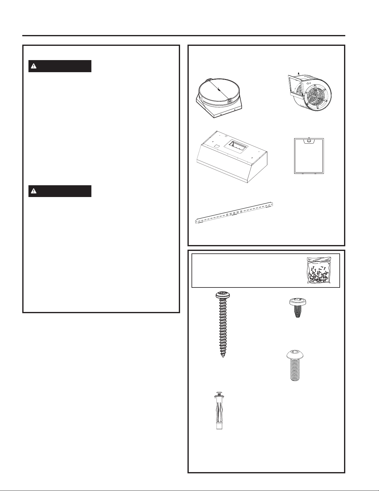
Preparación para la instalación
PREPARACIÓN PARA LA INSTALACIÓN
PLAN DE INSTALACIÓN
ADVERTENCIA
incendios y para que el aire salga de forma apropiada,
asegúrese de que el aire sea conducido hacia fuera.No
ventile el aire de la salida hacia espacios dentro de paredes
o cielorrasos o áticos, espacios muy bajos o garajes.
PIEZAS PROVISTAS PARA LA INSTALACIÓN
Ŷ 1 Paquete de Herramientas
Ŷ 1 Plantilla de Instalación
Ŷ Filtros de carbón (modo de recirculación)
PIEZAS NECESARIAS PARA LA INSTALACIÓN
Ŷ 1 Amortiguador de Refuerzo
Ŷ 1 Tapa de Pared o Techo (para instalación con
ventilación únicamente)
Ŷ Toda la Tubería Metálica
ADVERTENCIA
! RIESGO DE LESIONES PERSONALES
Debido al peso y tamaño de la base de la campana
extractora. Es recomendable que la campana extractora
sea instalada por 2 personas. Si la campana no es
elevada de forma correcta, se podrán producir daños
sobre el producto o lesiones personales.
NOTA: Esta campana puede ser instalada con conducto
o con recirculación. En una aplicación con conducto, esta
campana puede ser ventilada a través de la pared o del
cielorraso. Al ser instalada por recirculación, la campana
ventila hacia afuera los costados de la cubierta del
conducto.
NOTA: Antes de realizar cualquier corte o agujero para
la instalación, determine qué método de ventilación será
usado y con cuidado calcule todas las medidas.
A fin de reducir riesgos de
PIEZAS PROVISTAS:
Ubique las piezas embaladas con la campana.
Regulador
Superior
Motor
Cuerpo de la Campana
Soporte de Instalación Metálico
3 Filtros de Deflector
(4 con los modelos
de 48")
PAQUETE DE MATERIALES
Ubique y controle los contenidos.
AB
(Cant.: 4) Tornillos
PZ de 2.9mm x 6mm.
Usados para adherir el
regulador
(Cant.: 4) Tornillos de 8
x 1-3/4" AB. Usados para
montar la barra de instalación.
Use una broca de 1/8” para el
agujero piloto.
C
(Cant.: 2) Anclajes para pared
de yeso de 3/16” con tornillos.
Usados para los agujeros de los
tornillos de montaje inferiores.
Use una broca de 5/16” para el
agujero piloto.
49-2000708 Rev. 3 11
D
(Cant.: 4) Tornillos M4.
Usados para montar el
motor
Page 40
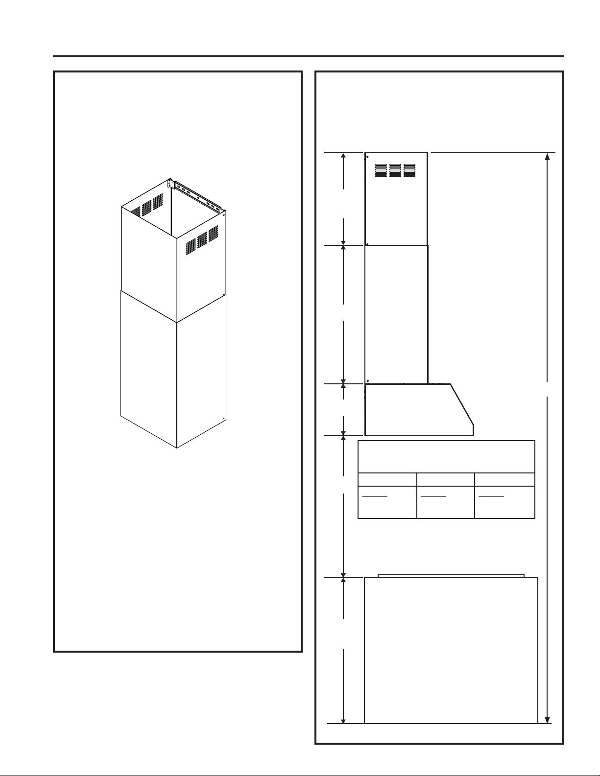
Preparación para la instalación
REQUISITOS SOBRE LA TAPA DEL
CONDUCTO
Los kits para la tapa del conducto se deberán adquirir
aparte. Le recomendamos que la campana de ventilación
y la tapa del conducto (de ser usadas) estén en sus
posiciones antes del enmarcado final y el acabado de
pared. Esto ayudará a ubicar los montantes, el conducto y
el cableado eléctrico de forma precisa.
DIMENSIONES DE LA INSTALACIÓN
Las tapas de los conductos de las campanas pueden
ser ajustadas en diferentes alturas de cielorrasos,
dependiendo de la distancia entre la parte inferior de la
campana y la superficie de cocción (distancia X). Consulte
la Tabla de Alturas de Instalación en la siguiente página.
5" Mín
25" Máx
19-1/2"
Tapa del Conducto
Superior
Tapa del Conducto Inferior
PREPARACIÓN PARA LA INSTALACIÓN
• El accesorio de la tapa del conducto viene con una tapa
de conducto inferior o superior y con el equipamiento
para la instalación.
• Las herramientas de instalación incluyen soportes de
montaje para asegurar las tapas del conducto a la
pared.
• Cuando no haya recirculación, los agujeros se podrán
ocultar colocando la tapa del conducto superior al revés.
• Para instalaciones en cielorrasos más altos de hasta 10'
8", use el kit de la Tapa del Conducto para Cielorrasos
Altos CX10DC9SPSS de 10'.
• Para instalaciones en cielorrasos más altos de hasta 12'
8", use el kit de la Tapa del Conducto para Cielorrasos
Altos CX10DC9SPSS de 12'.
• Consulte en la siguiente página información sobre la
altura de instalación de la tapa del conducto.
10"
Ejemplos de Mín. Requerido y Máx.
Recomendado para Alturas de Cielorraso para
el Kit de la Tapa de Conducto de 10” (Ventilada)
Eléctrico Gas
X
X = 24”
Y = Mín 7’ 6”
Máx 9’ 2”
X = Distancia desde la campana hasta la
superficie de cocción. (Varía dependiendo de la
instalación). Mínimo requerido de 24” sobre la
cocina eléctrica o mínimo de 30” sobre la cocina
a gas. El máximo recomendado es de 36”.
36" o
38"
X = 30”
Y = Mín 8’ 2”
Máx 9’10”
Cocina Típica
NOTA: 36” para cocina
eléctrica típica y 38” para
cocina a gas.
Y
X = 36”
Y = Mín 8’ 8”
Máx 10’ 4”
12 49-2000708 Rev. 3
Page 41
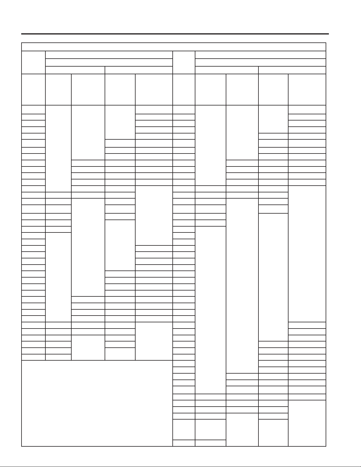
Preparación para la instalación
TABLA DE ALTURAS DE INSTALACIÓN
CX10DC9SPSS CX12DC9SPSS
Tapa del Conducto del Cielorraso de hasta 10 pies Tapa del Conducto del Cielorraso Alto de hasta 12 pies
Instalación sobre Cocina a Gas
Altura del
Cielorraso
(pies/
pulg.)
7' 6" 24 8' 7" 24
7' 7" 24-25 8' 8" 24-25
7' 8" 24-26 8' 9" 24-26
7' 9" 24-27 8' 10" 24-27
7' 10" 24-28 8' 11" 24 24-28
7' 11" 24 24-29 9' 0" 24-25 24-29
8' 0" 24-25 24-30 9' 1" 24-26 24-30
8' 1" 24-26 24-31 9' 2" 24-27 24-31
8' 2" 30 24-27 24-32 9' 3" 30 24-28 24-32
8' 3" 30-31 24-28 24-33 9' 4" 30-31 24-29 24-33
8' 4" 30-32 24-29 24-34 9' 5" 30-32 24-30 24-34
8' 5" 30-33 24-30 24-35 9' 6" 30-33 24-31 24-35
8' 6" 30-34 24-31
8' 7" 30 30-35 24-32 9' 8" 30-31 30-35 24-33
8' 8" 30-31
8' 9" 30-32 24-34 9' 10" 30-33 24-35
8' 10" 30-33 24-35 9' 11" 30-34
8' 11" 30-34
9' 0" 30-35 10' 1"
9' 1"
9' 2" 10' 3"
9' 3" 25-36 10' 4"
9' 4" 26-36 10' 5"
9' 5" 27-36 10' 6"
9' 6" 28-36 10' 7"
9' 7" 25-36 29-36 10' 8"
9' 8" 26-36 30-36 10' 9"
9' 9" 27-36 31-36 10' 10"
9' 10" 28-36 32-36 10' 11"
9' 11" 31-36 29-36 33-36 11' 0"
10' 0" 32-36 30-36 34-36 11' 1"
10' 1" 33-36 31-36 35-36 11' 2"
10' 2" 34-36 32-36 36 11' 3"
10' 3" 31-36 35-36 33-36 11' 4" 25-36
10' 4" 32-36 36 34-36 11' 5" 26-36
10' 5" 33-36 35-36 11' 6" 27-36
10' 6" 34-36 36 11' 7" 25-36 28-36
10' 7" 35-36 11' 8" 26-36 29-36
10' 8" 36 11' 9" 27-36 30-36
Altura de
Instalación
con
Ventilación
30-36
Altura de
Instalación con
Ventilación
(agujeros de
recirculación
ocultos)
30-36
Instalación sobre Cocina Eléctrica Instalación sobre Cocina a Gas Instalación sobre Cocina Eléctrica
Altura de
Instalación
con
Recirculación
24-33 9' 9" 30-32
24-36
Altura de
Instalación con
Ventilación
(agujeros de
recirculación
ocultos)
24-36
Altura del
Cielorraso
(pies/
pulg.)
9' 7" 30 30-34 24-32
10' 0" 30-35
10' 2"
11' 10" 28-36 31-36
11' 11" 29-36 32-36
12' 0" 31-36 30-36 33-36
12' 1" 32-36 31-36 34-36
12' 2" 33-36 32-36 35-36
12' 3" 31-36 34-36 33-36 36
12' 4" 32-36 35-36 34-36
12' 5" 33-36 36 35-36
12' 6" 34-36 36
Altura de
Instalación
con
Recirculación
30-36
Altura de
Instalación con
Ventilación
(agujeros de
recirculación
ocultos)
30-36
Altura de
Instalación
con
Recirculación
24-34
24-36
Altura de
Instalación con
Ventilación
(agujeros de
recirculación
ocultos)
PREPARACIÓN PARA LA INSTALACIÓN
24-36
12' 7" 35-36
12' 8" 36
49-2000708 Rev. 3 13
Page 42

Preparación para la instalación
PLANIFICACIÓN PREVIA
Planificación para la Instalación con Conducto
Ŷ Esta campana fue diseñada para ventilar de forma vertical
a través del cielorraso con un conducto cilíndrico de 8” o a
través de una pared trasera usando un codo de 90° y un
conducto cilíndrico de 8".
Ŷ Determine la ubicación exacta de la campana
de ventilación.
Ŷ Planifique el recorrido de la salida de ventilación hacia
el exterior. A fin de maximizar el rendimiento de la
ventilación del sistema de ventilación:
1. Minimice la longitud del conducto y el número de
transiciones y codos.
2. Mantenga un tamaño de conducto constante.
3. Selle todas las juntas con cinta para conductos a fin de
evitar pérdidas.
NOTA: No se recomienda una ventilación flexible. La
ventilación flexible crea una presión trasera y turbulencia del
aire que reduce el rendimiento significativamente.
Ŷ
Longitud máxima equivalente del conducto para 100 CFM:
150 pies para campanas de ventilación.
Ŷ
Instale una cubierta de pared o casquete de techo con
un regulador de tiro en la abertura exterior. Solicite por
adelantado la cubierta de pared o el casquete de techo y
cualquier transición o longitud de conducto necesarios.
Ŷ
PREPARACIÓN PARA LA INSTALACIÓN
Cuando corresponda, instale un sistema de reposición
(reemplazo) de aire de acuerdo con los requisitos del
código local de construcción. Use el kit de aire de
reposición JXMUA8.
El sistema de ventilación puede desembocar a través del
techo o de la pared. Para ventilar a través de una pared,
es necesario un codo de 90°que se encuentre instalado
inmediatamente sobre la campana.
Tapa del Techo
Agregue Aislante
y/o Sellador
Agregue cinta a
la junta
Campana
Planificación de Instalación con Recirculación
Se necesitarán un conducto de recirculación y un filtro de
carbón para la instalación de la recirculación, y los mismos
se deberán adquirir aparte.
Planificación del Suministro de Corriente
La ubicación de la conexión del suministro de corriente
aparece indicada en la sección de Ubicación del Cableado
Hogareño.
Conducto Redondo
Tapa de
Pared
Agregue Aislante
y/o Sellador
SUMINISTRO DE ENERGÍA
IMPORTANTE – (Tenga a bien leer cuidadosamente)
ADVERTENCIA
PARA SEGURIDAD PERSONAL, ESTE APARATO DEBE
CONECTARSE A TIERRA DE MANERA ADECUADA.
Quite el fusible o abra el interruptor de circuitos antes de
comenzar la instalación.
No utilice un cable de extensión o un enchufe adaptador
con este artefacto. Siga los Códigos Eléctricos Nacionales o
códigos y ordenanzas locales vigentes.
Suministro eléctrico
Estas campanas de ventilación deben contar con un
suministro de 120V, 60Hz, deben estar conectadas a un
circuito derivado con una adecuada conexión a tierra y
deben contar con la protección de un interruptor de circuitos
o un fusible con retraso de 15 o 20 amperios.
Ŷ El cableado debe ser de 2 hilos con conexión a tierra.
Ŷ Si el suministro eléctrico no cumple con los requisitos
anteriores, llame a un electricista con licencia antes de
continuar.
Ŷ Dirija el cableado doméstico lo más cerca posible a
la ubicación de la instalación, en el cielorraso o pared
trasera. Ver página 14 para más detalles.
Ŷ Conecte el cableado al cableado doméstico en
cumplimiento con los códigos locales.
Instrucciones de conexión a tierra
El conductor a tierra debe conectarse a un metal con
conexión a tierra, un sistema de cableado permanente o una
terminal o conductor de conexión a tierra del equipamiento
en la campana.
ADVERTENCIA
conductor de conexión a tierra del equipamiento puede
provocar un riesgo de descarga eléctrica. Consulte a un
electricista calificado o representante de servicio técnico
si tiene dudas sobre la correcta conexión a tierra del
artefacto.
Una conexión inadecuada del
14 49-2000708 Rev. 3
Page 43
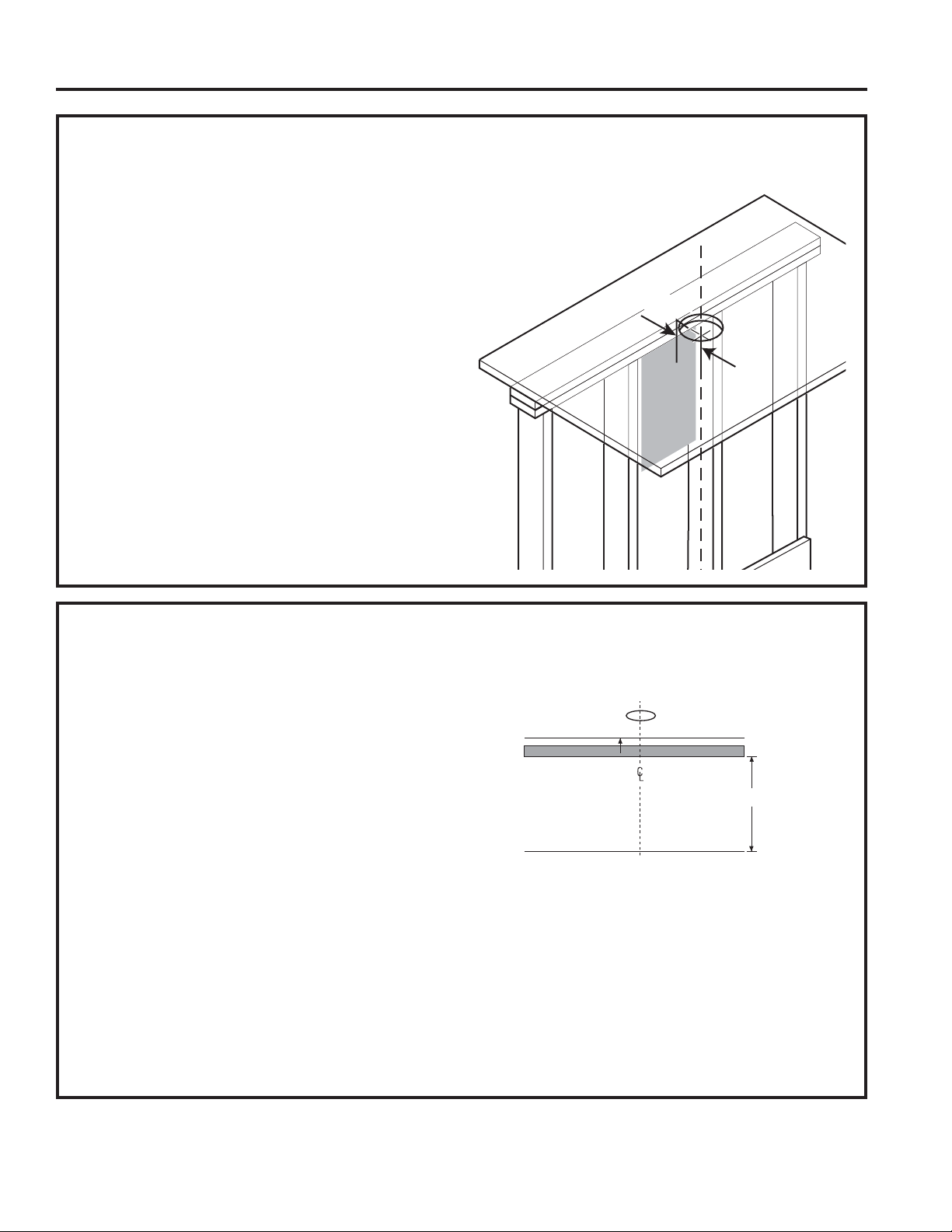
Preparación para la instalación
NUEVA CONSTRUCCIÓN, PLANIFICACIÓN PREVIA O REMODELACIÓN
NOTA: Para acceder a las instrucciones existentes, vaya a la siguiente sección.
Ŷ Para una instalación con conducto a través de la parte
superior, el agujero para el conducto del cielorraso deberá
estar centrado a una distancia de 6 ¼” de la pared trasera
terminada en el espacio de instalación.
Ŷ El tablero de la caja de empalmes de la campana está
ubicado a 10 ½” hacia la izquierda desde el centro de
la campana. Asegúrese de que haya una longitud del
cableado suficiente como para realizar conexiones
eléctricas.
6-1/4”
PREPARACIÓN PARA LA INSTALACIÓN
DETERMINE LAS UBICACIONES DE LA CAMPANA, EL CONDUCTO Y EL CABLEADO
• Esta campana se podrá instalar sobre la pared o debajo
del sofito o gabinete.
• Para instalar la campana en el sofito o gabinete, consulte
en la página 18 sobre un método de montaje alternativo.
• Con el producto se incluye una plantilla de montaje de
pared a fin de facilitar la instalación. En caso de no utilizar
la plantilla, siga las siguientes instrucciones.
• Mida la distancia deseada desde la parte inferior de la
campana hasta la superficie de cocción, con un mínimo de
24” sobre una cocina eléctrica o un mínimo de 30” sobre
una cocina a gas y un máximo recomendado de 36”.
• Use un nivel para dibujar la ubicación de la línea central de
la superficie de cocción o de la cocina.
• Mida 9” desde la línea horizontal que indica la parte inferior
de la campana. Dibuje otra línea horizontal para indicar la
parte inferior de la barra de instalación.
Para Conductos Verticales (Rectos):
• Si se ventilará a través del cielorraso, extienda la línea
central hacia adelante sobre el cielorraso.
- Mida 6 ¼” desde la pared de yeso para marcar el punto
central para un agujero de conducto con un diámetro de
8” en el cielorraso.
- Haga un agujero para conducto de 8" de diámetro sobre
el cielorraso.
Ventilación a Través del Sofito o Gabinete:
• Siga el mismo procedimiento para conductos verticales
(rectos) a través de la parte superior del sofito o gabinete.
Parte Superior de
la Campana
Parte Inferior de
la Campana
Para Conductos a Través de la Pared Trasera:
NOTA: Para ventilar a través de la pared trasera, es
necesario un codo de 90° que se encuentre instalado sobre
el regulador de la campana.
• Mida la altura desde la parte superior de la campana hasta
el centro del codo.
• Dibuje una línea horizontal sobre la pared que intersecta la
línea central.
• Haga un agujero de 8” de diámetro en el punto de
intersección para el conducto.
Cilindro de 8”
9”
49-2000708 Rev. 3 15
Page 44

Preparación para la instalación
DETERMINE LAS UBICACIONES DE LA CAMPANA, EL CONDUCTO Y EL CABLEADO
(Cont.)
Ubicación del Cableado Hogareño:
• La caja de empalmes se encuentra ubicada dentro del
cuerpo de la campana sobre el lado izquierdo. Consulte
las ilustraciones para conocer las ubicaciones del tablero
de la campana.
El cableado hogareño podrá ingresar a la caja de empalmes
desde la parte trasera o desde la parte superior de la
campana, sobre el lado izquierdo.
Para conducir el cableado hogareño a través del
cielorraso, sofito o gabinete:
• Haga un agujero de aproximadamente 1 ¼” de diámetro
en la parte delantera del cielorraso, a una distancia 9-3/4"
sobre la izquierda de la línea central.
Para conducir el cableado hogareño a través de la
pared:
• Mida 7 ¾" desde la parte inferior de la campana y marque
la ubicación.
• Haga un agujero de aproximadamente 1 ¼” de diámetro
en la ubicación marcada a una distancia 9-3/4" sobre la
izquierda de la línea central.
• Retire el tablero superior o trasero, dependiendo de su
instalación.
1-1/4"
Vista trasera
9-3/4"
Vista superior
9-3/4"
7-3/4"
PREPARACIÓN PARA LA INSTALACIÓN
16 49-2000708 Rev. 3
Page 45

Instrucciones de Instalación
INSTRUCCIONES DE INSTALACIÓN
1
INSTALACIÓN DEL SOPORTE DE
LA CAMPANA
IMPORTANTE: El marco deberá poder sostener 100 lbs
• Ubique mínimamente 2 vigas verticales para la barra de
instalación, golpeando la pared de yeso con un martillo
o usando un detector de vigas.
Nivele la barra de instalación y centre de izquierda a
•
derecha sobre la línea marcada. Sostenga la barra contra
la pared.
Barra de Instalación
9”
Mínimo de 24” sobre la cocina eléctrica o sobre
la superficie de cocción, o mínimo de 30” sobre
la cocina a gas o sobre la superficie de cocción,
y máximo de 36” recomendado
Línea Central
del Espacio de
Instalación
• Perfore agujeros piloto de 1/8” en las 2 ubicaciones de
montajes verticales, a través de los agujeros del soporte
de instalación. Asegure la barra de instalación con los
tornillos suministrados (A) como se muestra más arriba.
Perfore las Ubicaciones de los Agujeros de Montaje
Inferiores:
• Cuelgue la campana sobre la barra de instalación o use
la siguiente tabla para marcar las ubicaciones de los
agujeros de los tornillos. NOTA: Si la instalación se hará
en el sofito o gabinete, presione la campana hasta que
quede nivelada con el sofito o gabinete antes de marcar
las ubicaciones de los agujeros para los tornillos.
• Retire la campana y perfore agujeros de 5/16” en el
espacio libre sobre las posiciones “A” y “B”.
1
INSTALACIÓN DEL SOPORTE DE
LA CAMPANA (Cont.)
• Instale los anclajes de pared (C) golpeando los mismos
con un martillo para asentar los dientes de las bridas
sobre la pared. Esto evita que el anclaje ruede.
• Coloque los tornillos de anclaje hasta que los cilindros
queden enganchados dentro de la pared.
• Retire los tornillos de los anclajes de pared antes de
instalar la campana.
2
INSTALACIÓN DEL REGULADOR
IMPORTANTE: Retire la cinta de embalaje del regulador
y controle que este último se mueva libremente.
• Instale el regulador sobre el cuerpo de la campana
usando tornillos
(B) desde la
parte superior
de la campana,
como se muestra
en la siguiente
imagen.
• Use cinta
de conducto
para sellar la
conexión.
3
INSTALE LA CAMPANA EN LA PARED
• Pase el cableado hogareño a través del tablero sobre la
parte trasera o superior de la campana.
• Levante la campana y coloque la misma sobre los
ganchos en la barra de instalación. Permita que la
campana se deslice hasta su posición.
• Asegúrese de que la campana esté nivelada y centrada.
• Ajuste los tornillos de anclaje de pared (C) para finalizar
la instalación del cuerpo de la campana sobre la pared.
• Retire la tapa de la caja de empalmes dentro de la
campana.
Línea Central del
Espacio de Instalación
A
B
Parte Inferior
de la Campana
49-2000708 Rev. 3 17
Modelo de 30” 8-3/4”
Modelo de 36” 14”
“A” “B”
1-5/8”
Mínimo de 24” sobre la cocina
eléctrica o sobre la superficie
de cocción, o mínimo de 30”
sobre la cocina a gas o sobre
la superficie de cocción, y
máximo de 36” recomendado
Línea Central del Espacio
de Instalación
Page 46
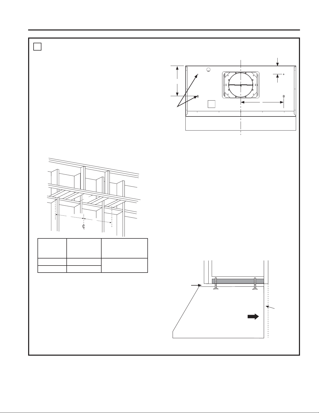
Instrucciones de Instalación
4
(Método Alternativo de Montaje) INSTALE LA CAMPANA EN EL
SOFITO O GABINETE
SALTEE ESTE PASO SI USARÁ UN MÉTODO DE
MONTAJE DE PARED
IMPORTANTE: El marco del sofito o gabinete deberán
poder sostener 100 lbs.
Cuando sea necesario, la campana podrá ser instalada de
modo que sea sostenida por el sofito o gabinete.
• El sofito deberá estar construido de vigas de 2”x4”.
• Use un nivel para dibujar la línea central de la superficie de
cocción o de la cocina.
• Continúe la línea central hacia delante en la parte inferior
del sofito.
• Instale los soportes de madera horizontales entre las vigas
de 2”x4”, a la distancia A hacia la izquierda y derecha, de
acuerdo con la siguiente tabla.
INSTRUCCIONES DE INSTALACIÓN
A
30” Modelos 8-3/4"
36” Modelos 14"
B
A
“A”
Línea Central
hasta la Viga
Central
“B”
Abertura para el
Conducto
8-3/8" x 11-1/4"
Pared Trasera
2-3/4"
10"
A
Keyholes
for Soffit
or Cabinet
Mounting
• Conduzca los tornillos de montaje (A) por las vigas hasta
que sobresalgan ¼”. Esta brecha de ¼” brindará espacio
libre para adherir las ranuras en la parte superior de la
campana.
• La campana también se deberá asegurar a la pared
trasera. Siga las instrucciones de la página 17, “Perfore las
Ubicaciones de los Agujeros de Montaje Inferiores” para la
instalación sobre la pared trasera.
• Siga las instrucciones de la página 16, “Ubicaciones del
Cableado Hogareño”, para la configuración del cableado.
• Levante la campana sobre los tornillos de montaje. Vuelva
a deslizar la misma sobre la pared trasera.
• Pase el cableado hogareño a través del tablero sobre la
parte trasera o superior de la campana.
• Ajuste los tornillos de montaje (A).
• Una vez que la campana se encuentre asegurada al sofito
o gabinete, coloque los tornillos (C) para asegurar la
campana a la pared trasera.
Figura C
Gabinete o Sofito
• Perfore dos agujeros piloto de 1/8” en una distancia de
10” desde la pared trasera en los soportes de madera
horizontales. Ésta es la distancia vertical entre las ranuras
de montaje y la pared trasera, como se muestra en la
Figura C.
• Perfore otros dos agujeros piloto de 1/8” en una distancia
de 2-3/4” desde la pared trasera en los soportes de
madera horizontales. Ésta es la distancia vertical entre
los agujeros de los tornillos de montaje y la pared trasera,
como se muestra en la Figura C.
• Para la ventilación superior, deje una abertura mínima
(Diám. B) para ubicar el regulador en el sofito o gabinete.
Brecha
de 1/4”
Adhiera las Ranuras de
las Cerraduras y Presione
Hasta Entrar en la Pared
Pared
Trasera
18 49-2000708 Rev. 3
Page 47

Instrucciones de Instalación
INSTRUCCIONES DE INSTALACIÓN
5
INSTALE EL MOTOR
1. Alinee la ventilación del motor con el regulador
superior, como se muestra en la siguiente figura.
2. Asegure el motor a la placa de montaje del mismo
usando los tornillos (D).
Ubicación de la
Placa
de Montaje del
Motor
Conexión
6
CONEXIÓN DE LA ELECTRICIDAD
Verifique que la corriente esté apagada en la fuente.
ADVERTENCIA
tiene 2 cables con uno a tierra, el instalador deberá
proveer una conexión a tierra. Cuando el cableado
hogareño sea de aluminio, asegúrese de usar un
compuesto antioxidante y conectores de aluminio a cobre
aprobados por UL.
• Retire la tapa de la caja de empalmes.
• Pase el cableado hogareño a través del tablero en la
parte superior o trasera de la campana y asegure el
mismo con un amortiguador de refuerzo.
Si el cableado del hogar no
3. Enchufe el motor en la conexión correspondiente sobre
la unidad de control.
• Use tuercas para cables de la lista de UL para conectar
los cables entrantes blanco con blanco y negro con
negro.
• Afloje el tornillo de conexión a tierra verde (con el
soporte de conexión a tierra) en la caja de empalmes.
Enrolle el cable hogareño de cobre sólido en dirección
horaria alrededor del tornillo de conexión a tierra verde
y sobre el soporte. De manera firme, ajuste el tornillo
sobre el rollo.
Soporte de Conexión
a Tierra
Tornillo Verde
de Conexión a
Tierra
• Reemplace la tapa de la caja de empalmes y asegúrese
de que los cables no hayan sufrido pellizcos.
NOTA: Para una instalación con cables: use la misma
sólo con los kits de conexión de cables para campanas
de cocina que fueron investigados y que se encontró que
su uso es aceptable con este modelo de campana para
cocina.
49-2000708 Rev. 3 19
Page 48

Instrucciones de Instalación
7
CONECTE EL CONDUCTO
A. Instalación de la Ventilación
• Conecte el conducto hogareño al regulador superior, como
se muestra en la siguiente imagen.
• Selle todas las conexiones con cinta para conductos.
Conducto
Hogareño
Cielorraso
B. Instalación de la Recirculación (no ventilada)
NOTA: Un conducto de recirculación (WB34X30519) y
un Filtro de Carbón (UXCF91) no se encuentran incluidos
con la campana y son necesarios para la instalación de la
recirculación.
1. Adhiera el conducto de recirculación al soporte de
montaje de la tapa del conducto con los tornillos
provistos.
2. Conecte el conducto desde la salida del extractor de la
campana hasta el conducto de recirculación.
conductos para sellar toda las conexiones de la caja de
recirculación y la salida del extractor.
Conducto de
Recirculación
Use cinta de
Soporte de
Montaje de
la Tapa del
Conducto
INSTRUCCIONES DE INSTALACIÓN
PRECAUCIÓN
planchas en la transición a la conexión del conducto. Hacer
esto impedirá el funcionamiento correcto de los reguladores.
Selle la conexión con cinta únicamente.
No use tornillos metálicos para
Use cinta (no use
tornillos)
20 49-2000708 Rev. 3
Page 49
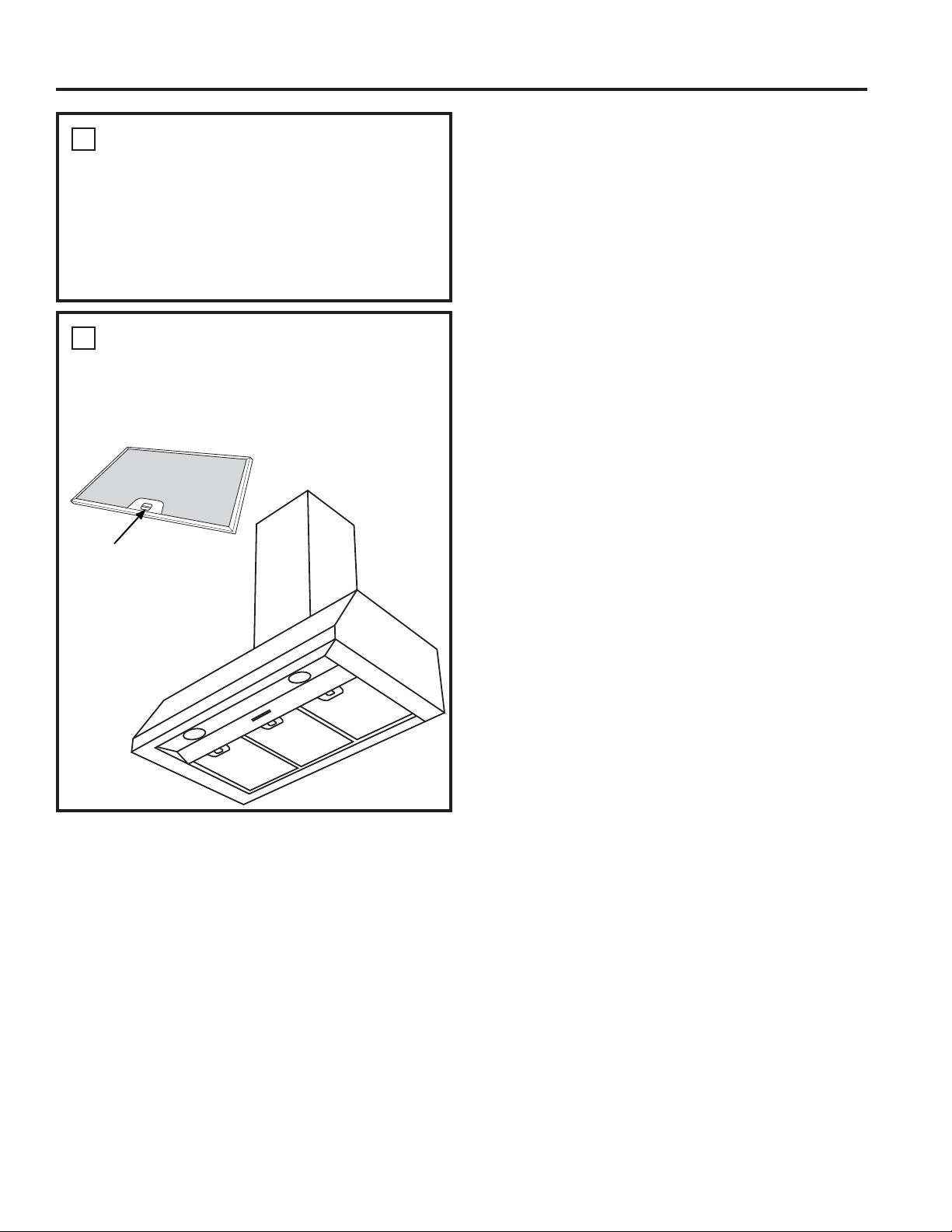
Instrucciones de Instalación
8
INSTALE LAS TAPAS DE LOS
CONDUCTOS
• Los Accesorios de la Tapa del Conducto están
disponibles en GEApplianceparts.com o llamando al
877.959.8688. Consulte la sección de Accesorios en la
página 27.
• Siga las instrucciones incluidas con el accesorio de la
tapa del conducto para instalar las tapas de conducto.
9
INSTALACIÓN DE LOS
FILTROS
• Siga las instrucciones de “Filtros” en la página 7
para instalar o retirar filtros.
INSTRUCCIONES DE INSTALACIÓN
Bloqueo del Filtro
49-2000708 Rev. 3 21
Page 50

Instrucciones de Instalación
TECNOLOGÍA DE REPOSICIÓN DE AIRE
Esta operación deberá ser realizada por un técnico o instalador calificado.
Nota para los Instaladores e Inspectores: Este producto está equipado con una función de instalación simple que limita
los niveles máximos de CFM, a fin de cumplir con ciertos códigos o regulaciones locales. Es posible que este método de
instalación no sea necesario en todas las instalaciones; para acceder a más pautas, por favor consulte sus códigos locales.
PRECAUCIÓN
La campana deberá ser desconectada de la alimentación de corriente principal, antes de seguir
las instrucciones de conversión que figuran a continuación. Si no se siguen estos pasos, se podrán producir lesiones
personales o daños sobre el producto.
Para modificar la unidad (si es necesario para cumplir
con los códigos locales): 390CFM
Por diseño, la velocidad máxima del calefactor es superior a
los 400 CFM. Si los códigos locales requieren una reducción
de los CFM, modifique el cableado como se describe a
continuación:
1. Retire los filtros de grasa.
2. Desconecte todos los arneses de la caja de control
superior ubicada sobre el lado derecho del motor.
Conector del Arnés del Motor
3. Afloje los tornillos sobre la parte superior de la caja de
control y deslice la misma para retirarla de la campana.
4. Desinstale la tapa de la caja de control.
5. Para un máximo de 390 CFM con 4 velocidades (Baja,
Media, Alta y Aumentada):
INSTRUCCIONES DE INSTALACIÓN
i. Desconecte los conectores del cable MARRÓN.
II. Retire la tapa adherida al conector del cable ROJO.
iii. Coloque el conector correspondiente al cable
Rojo
Marrón
Blue
Red
Marrón
Red
Marrón
MARRÓN y al cable ROJO.
iv. Adhiera la tapa al enchufe del cable MARRÓN
abierto.
6. Instale la caja de control y asegure la misma al soporte
de la campana usando los dos tornillos.
Arnés del Motor
Motor Harness
7. Conecte todos los arneses sobre la parte superior de la
caja de control.
8. Vuelva a instalar los filtros de Grasa.
Nota para los Inspectores: A fin de verificar la instalación
Configuración del
Cableado Instalado de
Fábrica
Configuración del
Cableado Aumentado
Máx. de 390 CFM
de este producto, controle las conexiones del cableado del
motor como se describe más arriba.
Rojo
Red
Blue
Marrón
Red
Arnés del Motor
Motor Harness
22 49-2000708 Rev. 3
Page 51

Consejos para la Solución de Problemas... Antes de solicitar el servicio técnico
¡Ahorre tiempo y dinero! Primero revise los cuadros que aparecen en las siguientes páginas y es posible que no necesite solicitar
reparaciones.
Problema Causas posibles Qué hacer
El Ventilador/ la Luz no
funciona cuando el botón
está en ON (Encendido)
Ruido de flujo de aire muy
elevado o anormal
El ventilador no hace
circular aire o desplaza
desplaza el aire más
despacio que lo normal y/o
hace ruido de flujo de aire
elevado o anormal
El ventilador continúa
encendiéndose y
apagándose.
La campana no funciona de
forma remota
El fusible puede haberse quemado o
el interruptor decircuitos puede haber
saltado.
Tamaño de conducto incorrecto
utilizado en la instalación.
Obstrucciones en el conducto. Verifique que no haya obstrucciones en la
La hoja del regulador de tiro de la
cubierta de pared o casquete de
techo puede estar cerrada.
El filtro de grasa metálico y el filtro de
carbón (si lo hubiera) pueden estar
sucios.
Es posible que el motor se esté
sobrecalentando y apagando solo.
Esto puede ser nocivo para el motor.
Problemas en el enrutador, no hay
señal inalámbrica, etc.
La campana no se encuentra
conectada.
Cambie los fusibles o reconfigure el interruptor de
circuitos.
Esta campana requiere un conducto de 8” para
funcionar de manera óptima. El uso de un conducto
más pequeño hará que la ventilación se reduzca.
Minimice la longitud del conducto y el número de
transiciones y codos. Los técnicos de GE Appliances
no pueden corregir este problema si hay una
instalación inadecuada.
ventilación. Controle que la cubierta de pared o
casquete de techo tengan una hoja o puerta.
Asegúrese de que el regulador de tiro se mueva
libremente. Las hojas del regulador de tiro pueden
darse vuelta y no se abrirán por completo cuando
esto suceda. Ajústela con la posición original.
Limpie el filtro de grasa metálico y vuelva a colocar
el filtro de carbón (si lo hubiera). Ver Cuidado y
limpieza de la campana de ventilación.
Asegúrese de que los filtros estén limpios. Si el ciclo
de encendido y apagado continúa, comuníquese al
servicio técnico.
Para solicitar asistencia para la conectividad
de la red inalámbrica de la campana, por favor
comuníquese al 800.220.6899.
CONSEJOS PARA LA SOLUCIÓN DE PROBLEMAS
49-2000708 Rev. 3 23
Page 52

Garantía Limitada de la Cocina Eléctrica de GE Appliances
GEAppliances.com
Todo el servicio de garantía es provisto por nuestros Centros de Servicio de Fabricación, o un técnico autorizado de Customer Care®.
Para programar una visita del servicio técnico a través de Internet, visítenos en www.geappliances.com/service_and_support/, o
llame al 800.GE.CARES (800.432.2737). Cuando llame para solicitar el servicio, tenga los números de serie y modelo disponibles.
Para realizar el servicio técnico de su electrodoméstico, se podrá requerir el uso de datos del puerto de abordaje para su diagnóstico.
Esto da al técnico del servicio de fábrica de GE Appliances la habilidad de diagnosticar de forma rápida cualquier problema con
su electrodoméstico, y de ayudar a GE Appliances a mejorar sus productos al brindarle a GE Appliances la información sobre su
electrodoméstico. Si no desea que los datos de su electrodoméstico sean enviados a GE Appliances, solicitamos que le indique a su
técnico no entregar los datos a GE Appliances en el momento del servicio.
Por el Período de GE Appliances reemplazará
Un Año
Desde la fecha de la
compra original
Qué no cubrirá GE Appliances:
GARANTÍA LIMITADA
Ŷ Viajes del técnico del servicio a su hogar para enseñarle
sobre cómo usar el producto.
Ŷ ,QVWDODFLyQHQWUHJDRPDQWHQLPLHQWRLQDGHFXDGRV
Ŷ )DOODVGHOSURGXFWRHQFDVRGHDEXVRPDOXVRPRGLILFDFLyQ
o uso para propósitos diferentes al original o uso comercial.
Ŷ 5HHPSOD]RGHIXVLEOHVGHODFDVDRUHLQLFLRGHGLV\XQWRUHV
Ŷ 'DxRVRFDVLRQDGRVVREUHHOSURGXFWRSRUDFFLGHQWH
incendio, inundaciones o catástrofes naturales.
Ŷ 'DxRVLQFLGHQWDOHVRFRQVHFXHQWHVFDXVDGRVSRUSRVLEOHV
defectos sobre este producto.
Cualquier pieza del producto de cocción que falle debido a un defecto en los materiales o la
fabricación. Durante esta garantía limitada de un año, GE Appliances también proveerá, sin costo,
todo el trabajo y costos del servicio relacionados con el reemplazo de la pieza defectuosa.
Ŷ 'DxRVVREUHHODFDEDGRWDOHVFRPRy[LGRVREUHOD
superficie, deslustres o manchas pequeñas no informadas
dentro de las 48 horas luego de la entrega.
Ŷ 'DxRFDXVDGRGHVSXpVGHODHQWUHJD
Ŷ 3URGXFWRQRDFFHVLEOHSDUDEULQGDUHOVHUYLFLRUHTXHULGR
Ŷ 0DUFDVRPDQFKDVLQFOX\HQGRPDQFKDVGHy[LGRVREUH
la superficie) que pueden ser eliminadas siguiendo las
instrucciones de limpieza.
Ŷ 6ROLFLWHHOVHUYLFLRWpFQLFRSDUDUHSDUDURUHHPSOD]DUODV
lámparas, excepto las lámparas LED.
EXCLUSIÓN DE GARANTÍAS IMPLÍCITAS
Su única y exclusiva alternativa es la reparación del producto, como se indica en la Garantía Limitada. Las
garantías implícitas, incluyendo garantías implícitas de comerciabilidad o conveniencia sobre un propósito
particular, se limitan a un año o al período más corto permitido por la ley.
Esta garantía limitada se extiende al comprador original y a cualquier dueño subsiguiente de productos comprados
para uso hogareño dentro de EE.UU. Si el producto está en un área donde no se encuentra disponible un Proveedor
Autorizado del Servicio Técnico de GE Appliances, usted será responsable por el costo de un viaje o se podrá
requerir que traiga el producto a una ubicación del Servicio Técnico de GE Appliances autorizado para recibir el
servicio. En Alaska, la garantía limitada excluye el costo de envío o llamadas del servicio a su hogar. Algunos estados
no permiten la exclusión o limitación de daños fortuitos o consecuentes. Esta garantía limitada le da derechos legales
específicos y es posible que tenga otros derechos legales que varían entre un estado y otro. Para conocer cuáles son
sus derechos legales, consulte a la oficina de asuntos del consumidor local o estatal o al Fiscal de su estado.
Garante: GE Appliances, a Haier company
Garantías Extendidas: Adquiera una garantía extendida de GE Appliances y conozca los descuentos especiales que
están disponibles mientras su garantía aún está vigente. Puede acceder a la misma a través de Internet en cualquier
momento en
geappliances.com/extended-warranty
o llamando al 800.626.2224 durante el horario comercial. Los Servicios para los GE Appliances aún estarán
disponibles cuando su garantía caduque.
Abroche su recibo aquí. Para acceder al servicio técnico de acuerdo con
la garantía deberá contar con la prueba de la fecha original de compra.
24 49-2000708 Rev. 3
Page 53

Accesorios
¿Busca Algo Más?
GE Appliances ofrece una variedad de accesorios para
mejorar sus experiencias de cocción y mantenimiento!
Para acceder a números telefónicos e información de sitios
Web, consulte la página de Soporte para el Consumidor.
Estos y otros productos están disponibles:
Piezas
Filtros de grasa
Tapas de Conductos
Filtros de Carbón
Kit de Recirculación
Control Remoto
Panel de Relleno del Gabinete de 15”
Kit del Cable de Corriente
Suministros de Limpieza
Limpiadores de Acero Inoxidable CitriShine
Limpiador para Electrodomésticos de Acero Inoxidable
Bar Keepers Friend Soft Cleanser™
ACCESORIOS
49-2000708 Rev. 3 25
Page 54
Soporte para el Consumidor
Sitio Web de GE Appliances
¿Desea realizar una consulta o necesita ayuda con su electrodoméstico? ¡Intente a través del Sitio Web de GE Appliances las
24 horas del día, cualquier día del año! Usted también puede comprar más electrodomésticos maravillosos de GE Appliances y
aprovechar todos nuestros servicios de soporte a través de Internet, diseñados para su conveniencia.
En EE.UU.: GEAppliances.com
Registre su Electrodoméstico
¡Registre su electrodoméstico nuevo a través de Internet, según su conveniencia! Un registro puntual de su producto permitirá
una mejor comunicación y un servicio más puntual de acuerdo con los términos de su garantía, en caso de surgir la necesidad.
También puede enviar una carta en la tarjeta de inscripción preimpresa que se incluye con el material embalado.
En EE.UU.: GEAppliances.com/register
Servicio Programado
El servicio de reparación de expertos de GE Appliances está a sólo un paso de su puerta. Conéctese a través de Internet y programe
su servicio a su conveniencia cualquier día del año. En EE.UU.: GEAppliances.com/ge/service-and-support/service.htm
o comuníquese al 800.432.2737 durante el horario de atención comercial.
Garantías Extendidas
Adquiera una garantía extendida de GE Appliances y conozca los descuentos especiales que están disponibles mientras su
garantía aún está vigente. La puede adquirir en cualquier momento a través de Internet. Los servicios de GE Appliances aún
estarán allí cuando su garantía caduque.
En EE.UU.: GEAppliances.com/ge/service-and-support/shop-for-extended-service-plans.htm
o comuníquese al 800.626.2224 durante el horario de atención comercial.
SOPORTE PARA EL CONSUMIDOR
Conectividad Remota
Para solicitar asistencia para la conectividad de red inalámbrica (para modelos con acceso remoto),
visite nuestro sitio web en GEAppliances.com/ge/connected-appliances/ o comuníquese al 800.220.6899 en EE.UU.
Piezas y Accesorios
Aquellos individuos calificados para realizar el servicio técnico de sus propios electrodomésticos podrán solicitar el envío de
piezas o accesorios directamente a sus hogares (se aceptan las tarjetas VISA, MasterCard y Discover). Ordene hoy a través de
Internet durante las 24 horas, todos los días. En EE.UU.: GEApplianceparts.com o de forma telefónica al 877.959.8688 durante
el horario de atención comercial.
Las instrucciones que figuran en este manual cubren los procedimientos que serán realizados por cualquier usuario.
Otros servicios técnicos generalmente deben ser derivados a personal calificado del servicio. Se deberá tener cuidado,
ya que una reparación indebida podrá hacer que el funcionamiento no sea seguro.
Contáctenos
Si no se encuentra satisfecho con el servicio que recibió de GE Appliances, comuníquese con nosotros a través de nuestro sitio
Web con todos los detalles, incluyendo su número telefónico, o escriba a:
En EE.UU.: General Manager, Customer Relations | GE Appliances, Appliance Park | Louisville, KY 40225
GEAppliances.com/ge/service-and-support/contact.htm
26 49-2000708 Rev. 3
 Loading...