

Page 1
Quick Start Guide
UVS-ABD1300 Eyeball IP Dome
Before attempting to connect or operate this product,
please read these instructions carefully and save this manual for future use.
UVSABDV10-QG-A
Page 2

© 2017 USA Vision Systems Inc. All rights reserved.
Under the copyright laws, this manual may not be copied, in whole or in part,
without the written consent of USA Vision.
Every effort has been made to ensure that the information in this manual is
accurate. USA Vision makes no expressed or implied warranty of any kind and
assumes no responsibility for erro rs or omissions. No liability is assumed for
incidental or consequential damages arising from the use of the information or
products contained herein. Features and specifications are subject to change
without notice.
Note: No memory card slot or local storage function for Argentina.
USA Vision Systems Inc.
9235 Research Drive,
Irvine, CA 92618, USA
Tel: +1-949-583-1519
Fax: +1-949-583-1522
http://www.usavisionsys.com
Trademarks used in this manual: USAVision and the USAVision logo are
trademarks of USA Vision Systems Inc. Windows is the registered trademark
of Microsoft Corporation.
January 2017
Page 3

Contents
Note for Connecting to GV-VMS / DVR / NVR......................................ii
Note for Installing Camera Outdoor....................................................iii
Introduction ....................................................................................
1.
1.1 Packing List ........................................................................................................... 1
1.2 Optional Accessories ............................................................................................. 2
1.3 Overview................................................................................................................ 2
Installation ......................................................................................
2.
Waterproofing the Cable ................................................................
3.
1
4
7
4. Accessing the Camera ...................................................................9
4.1 Looking Up the Dynamic IP Address...................................................................... 9
4.2 Configuring the IP Address ...................................................................................11
5. The Web Interface......................................................................... 12
6.
Upgrading System Firmware .......................................................
7.
Restoring to Factory Default........................................................
14
15
i
Page 4

Note for Connecting to GV-VMS / DVR / NVR
The Eyeball Dome is designed to work with GV-VMS / DVR / NVR, a video management
system. Once the camera is connected to the GV-VMS / DVR / NVR, the resolution set on the
GV-VMS / DVR / NVR will override the resolution set on the camera’s Web interface. You can
only change the resolution settings through the Web interface when the connection to the
GV-VMS / DVR / NVR is interrupted.
ii
Page 5
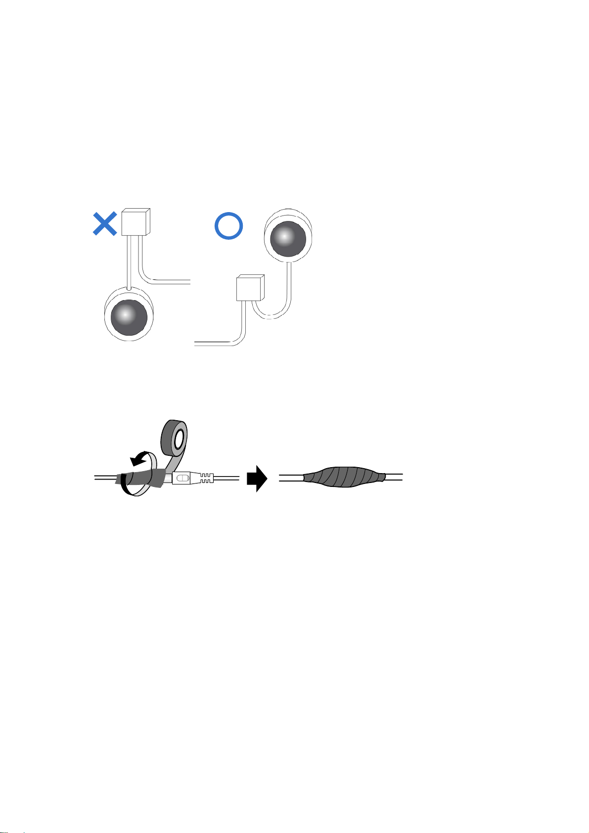
Note for Installing Camera Outdoor
When installing the camera outdoor, be sure that:
1.
The camera is set up above the junction box to prevent water from entering the camer
along
the cables.
2.
Any power, audio and I/O cables are waterproofed using waterproof silicon rubber or t
lik
e.
a
he
3.
The screws are tightened and the cover is in place after opening the camera cover.
iii
Page 6

Introduction
1
1. Introduction
Welcome to the Eyeball IP Dome Quick Start Guide. In the following sections, you will learn
the basic installations and configurations. For details, see its User’s Manual.
1.1 Packing List
Eyeball Dome
Waterproof Rubber Set
Screw x
Screw Anchor x
Drill Template Paster
Software Download Gu
W
2
2
arranty Card
ide
1
Page 7

1.2 Optional Accessories
Optional accessories can expand the capabilities and versatility of your camera. Contact your
dealer for more information.
Model Number
GV-Mount211 Wall Mount Bracket
GV-Mount212 Wall Box Mount
GV-PA191
Name
Power over Ethernet
(PoE) Adapter
Details
Dimensions: 233 x 126 x 126
mm (9.2” x 5” x 5”)
Weight: 0.92 kg (2.0 lb)
Dimensions: Φ126 x 36 mm
(5.0” x 1.4”)
Weight: 0.18 kg (0.4 lb)
The
GV-PA191 is a Power over
Ethernet (PoE) adapter
designed to provide power to
the IP device through a single
Ethernet cable.
GV-POE Switch The GV-POE Switch is designed to provide power along
with network connection for IP devices. The GV-POE
Switch is available in various models with different
numbers and types of ports.
Power Adapter Contact your sales representative for the countries and
areas supported.
2
Page 8

1.3 Overview
Introduction
1
No. Description
1 Bottom ring
2 Housing
3 Lens
4 Infrared LED
5
6 Ethernet connector / PoE
Power connector (DC 12 V)
An optional power adapter is required.
3
Page 9

2. Installation
The Eyeball Dome is designed for outdoors. With the standard package, you can install the
camera on the ceiling. Or you can purchase optional mounting accessories to mount the
camera on a wall.
Below are the instructions for Ceiling Mount. There are two kinds of Ceiling Mount:
Concealed Installation and Open Installation. In Concealed Installation, the cables are
hidden in the ceiling. In Open Installation, the cables are led out from the open slot on the
bottom ring.
For Concealed Installation
1. Stick the drill template paster to the ceiling, and then drill two 30-mm deep guide holes
according to the drill template.
2.
Insert the screw anchors.
4
Page 10

3.
Remove the bottom ring by turning it anticlockwise.
Installation
2
4. Connect the cables and then secure the camera.
5. Adjust the monitoring direction.
5
Page 11

6. Mount the bottom ring.
For Open Installation
Lead the cables out from the open slot on the bottom ring before screwing the camera to the
ceiling as shown in step 4 in For Concealed Installation.
Note: You can optionally purchase GV-Mount211 for Wall Bracket Mount. For details, see its
User’s Manual.
6
Page 12

3
3. Waterproofing the Cable
Waterproof the Ethernet cable by using the supplied waterproof rubber set.
1. Attach the seal ring to the RJ-45 plug.
Waterproofing the Cable
Sealring
2. Insert the waterproof components through the Ethernet cable as shown below.
3
2
Insertinorder
3.
Insert the cylindrical waterproof ring into waterproof bolt.
Cylindricalwaterproofring
Waterproofbolt
7
Page 13

4. Insert the cable into the RJ-45 plug and screw the waterproof bolt in.
5. Screw in the waterproof bolt lid.
Bolt lid
6. Finish the waterproof Installation.
8
Page 14

Accessing the Camera
4
4. Accessing the Camera
4.1 Looking Up the Dynamic IP Address
By default, when the camera is connected to LAN with a DHCP server, it is automatically
assigned with a dynamic IP address. Follow the steps below to look up its IP address.
Note: The computer you use to configure the IP address must be under the same LAN with
your camera.
1. Download and install the GV-IP Device Utility program from
http://www.geovision.com.tw/english/5_8.asp
2. On the GV-IP Utility window, click the
the same LAN. Click the Name or Mac Address column to sort.
3. Find the camera with its Mac Address, click on its IP address and select Web Page.
button to search for the IP devices connected in
9
Page 15

4. The login page appears.
5. For the first time accessing the Web interface, download and install the plug-in.
Type the default ID and password admin and click Login to log in.
6.
10
Page 16

Accessing the Camera
4
4.2 Configuring the IP Address
If the camera is connected to LAN without a DHCP server, the default IP address will be
192.168.0.10. Follow the steps below to modify the IP address to avoid IP conflict with other
GV-IP devices on the same LAN.
1. Open your web browser, and type the default IP address http://192.168.0.10.
2. In both Login and Password fields, type the default value admin. Click Login.
3. Click Setup, select Common in the left menu and select Ethernet.
4. Select Static IP from the IP Obtain Mode drop-down list.
5. Enter the IP address, subnet mask, and default gateway address. Make sure that the IP
address of the camera is unique in the network.
6. Click Save.
11
Page 17

5. The Web Interface
Once you log in the Web interface, you will see the live view as shown below.
No. Name Function
Set the display ratio of the image.
Scale: display images by 16:9.
1 Proportional
2 Live Stream
3 Image Open the image setting page.
4 Full Screen Mode Display in full screen mode.
5 Play/Stop Play or stop live video.
6 Snapshot Take a snapshot of the current image displayed on the PC.
7 Local Recording Start or stop local recording.
Stretch: display images by window size.
Original: display images in its original size.
Select a live video stream: main stream, sub stream or third
stream.
12
Page 18

5
The Web Interface
8 Digital Zoom Start
or stop digital zoom.
9 Reset the packet loss rate to zero.
10 Display packet loss rate and bit rate information in the bottom.
Note:
1. The paths for saving snapshots and local recordings are set in System Configuration.
2. The buttons (No. 9 and No. 10) will appear on the floating toolbar after you move the
mouse cursor on a live view window.
3. Click the button (No. 10) to display the bottom information. Click this button again, the
bottom information is displayed if the mouse cursor is moved on a live view window or
on the bottom information, and it hides automatically if the mouse cursor remains on a
live view window for 3 seconds or leaves the window.
13
Page 19

6. Upgrading System Firmware
We periodically release the updated firmware on the website. To load the new firmware into
the camera, follow the instructions below.
1. At the top of the Web interface, click Setup.
2. In the left menu, select System and select Maintenance. This page appears.
3. Click the Browse button to locate the firmware file (.zip) saved at your local computer.
4. Optionally select Upgrade Boot Program to reboot the camera after a successful upgrade.
5. Click the Upgrade button to process the upgrade.
14
Page 20

Restoring to Factory Default
7
7. Restoring to Factory Default
You can restore the camera to factory default settings using the Web interface.
1. At the top, click Setup.
2. In the left menu, select System and select Maintenance.
3. Under the Config Management section, click the Default button.
Note: There is no default button on the camera.
15
 Loading...