

Page 1
GV-IP Camera
Firmware Manual
Before attempting to connect or operate this product,
please read these instructions carefully and save this manual for future use.
ICH265HISI2V10-A
Page 2

© 2017 GeoVision, Inc. All rights reserved
Under the copyright laws, this manual may not b
part, without the written consent of GeoVision.
Every eff
is accurate. GeoVisi
any kind and assu
liability is assu
the use of the info
specifications are subject to change without notic
card slot or local storage function for Argenti
GeoV
9F, No. 246, Sec. 1, Neihu Rd.,
Neihu District, Taipei, Taiwan
Tel: +886-2-8797-8377
Fax: +886-2-8797-8335
http://www.geovision.com.tw
Trademarks used in this manual: GeoVision, the GeoVision logo and GV
series products are trademarks of GeoVision, Inc. Windows is the
registered trademark of Microsoft Corporation.
June 2017
ort has been made to ensure that the information in this manual
on, Inc. makes no expressed or implied warranty of
mes no responsibility for errors or omissions. No
med for incidental or consequential damages arising from
rmation or products contained herein. Features and
ision, Inc.
.
e copied, in whole or in
e. Note: no memory
na.
Page 3

Contents
Preface .............................................................................. vi
Naming and Definition..........................
Note for Connecting to GV-DVR / NVR
Note for Recording .......................................................
Note for GV-BX2600..............................
Frame Rate ............................................
Browser..................................................
ording ..............................................
Rec ....................... xviii
e for GV-EVD5100 / EFD5101 / EBL
Not 5101.................xix
pter 1 Intr
Cha .............................1
1.1 System Requirement..........................
oduction
........................
.......................... xv
/ GV-VMS....... xvi
xvii
....................... xviii
....................... xviii
....................... xviii
....................................1
Chapter 2 Getting Started ................................................3
2.1 Accessing the Live View ....................
2.1.1 Checking the Dynamic IP Addre
2.1.2 Configuring the IP Address ..........................................6
2.1.3 Configuring the Wireless Connection ...........................8
2.2 Adjusting Image Clarity........................................................12
2.2.1 Using Focus Adjustment Cap.....................................16
2.2.2 Locations of Adjustment Screws ................................17
2.3 Configuring the Basics.........................................................20
....................................3
ss ...............................4
Chapter 3 Accessing the Camera..................................21
3.1 Accessing Your Surveillance Images..................................21
3.2 Functions Featured on the Main Page.................................23
3.2.1 The Live View Window...............................................24
3.2.2 The Control Panel of the Live View Window...............30
i
Page 4

3.2.3 Snapshot of Live Video ..............................................37
3.2.4 Video Recording ......................
3.2.5 Picture-in-Picture and Picture-a
3.2.6 Alarm Notification.....................
onfiguration.
3.2.7 Video and Audio
3.2.8 Remote Configuration ..............
3.2.9 Camera Name Display.............
3.2.10 Image Enhancement
.2.11 Visual PTZ.............................
3
3.2.12 Digital PTZ.............................
3.2.13 I/O Control .............................
3.2.14 Visual Automation..................
3.2.15 Network Status.......................
C
..............
Chapter 4
4.1 Video and Motion....................................
4.2 Video Analysis ..........................................................................82
4.3 I/O Settings..............................................................................104
Administrator Mode ...........
4.1.1 Video Settings.................................
4.1.2 Motion Detection.............................
4.1.3 Privacy Mask...................................
4.1.4 Text Overlay ...................................
4.1.5 Tampering Alarm.............................
4.1.6 Visual Automation............................................................... 80
4.2.1 Motion Detection................................................................. 85
4.2.2 Advanced Video Analysis.................................................... 89
4.2.3 Unattended Object / Missing Object Detection..................... 99
4.2.4 Tampering Alarm...............................................................102
4.3.1 Input Settings.................................................................... 105
4.3.2 Output Settings .................................................................107
4.3.3 PTZ Settings ..................................................................... 108
..................................37
nd-Picture View .........38
..................................41
..................................43
..................................45
..................................45
..................................45
..................................46
..................................49
..................................51
..................................52
..................................53
...........................54
..................................57
....................................58
....................................71
....................................74
....................................75
....................................77
ii
Page 5

4.4 Events and Alerts....................................................................109
4.4.1 E-mail .............................................
4.4
.
2 FTP.................................................
4.4.3 Center V2..........................................................................
4.4.4 Vital Sign Monitor............................
4.4.5 Backup Center ................................
4.4.6 Video Gateway / Recording Server..
4.4.7 ViewLog Server...............................
4.4.8 RTSP/ONVIF ..................................
4.4.9 Speaker..........................................
4.5 Monitoring..........................................................
4.5.1 Monitoring Settings for GV-EBL2101
4.6 Recording Schedule ...............................
4.6.1 Recording Schedule Settings ..........
4.6.2 I/O Monitoring Settings....................
4.7 Remote ViewLog .....................................
4.8 Network ...................................................
4.8.1 LAN Configuration.............................................................
4.8.2 Wireless Client Mode ......................
4.8.3 Advanced TCP/IP............................
4.8.4 UMTS Settings.................................................................. 146
4.8.5 IP Filter Settings................................................................ 149
4.8.6 SNMP Settings.................................................................. 151
..................................110
..................................112
115
..................................117
.................................. 119
.................................. 122
.................................. 124
..................................125
..................................128
.....................129
/ 2111 / 3101............132
................................133
.................................. 133
..................................134
................................135
................................136
136
..................................140
..................................142
4.9 Management............................................................................153
4.9.1 Date & Time Settings ........................................................153
4.9.2 Storage Settings ...............................................................155
4.9.3 User Account ....................................................................163
4.9.4 Log Information................................................................. 164
4.9.5 Tools.................................................................................165
4.9.6 Language..........................................................................168
iii
Page 6

Chapter 5 Recording and Playback ............................169
5.1 Recording................................................................................169
5.2 ................170
yback..................................................................
Pla
5.2.1 Playback from the Memory Card ....................................... 170
2 Playback over Network.....................
5.2.
5.2.3 Access to the Recorded Files throug
5.2.4 Playback of Daylight Saving Time Ev
Chapter 6 Advanced Applications .....
6.1 U .....................180
pgrading System Firmware.............................
6.1.1 Using the Web Configuration Interfa
6.1.2 Using the IP Device Utility ...............
6.2 Backing Up and Restoring Settings.......
6.3 Changing Password ................................
6.4 Verifying Watermark...............................
6.4.1 Accessing AVI Files ........................
6.4.2 Running Watermark Proof.................................................
6.4.3 The Watermark Proof Window.........
6.5 Downloading Videos from the Micro SD
6.5.1 Installing the GV-SDCardSync Utility................................. 196
6.5.2 The GV-SDCardSync Utility Window .................................200
Chapter 7 DVR Configurations ....................................202
7.1 Setting up an IP Camera on GV-DVR / NVR...........................204
7.1.1 Customizing IP Camera Settings on GV-DVR / NVR .........207
7.2 Setting Up IP Cameras on GV-VMS........................................209
7.3 Remote Monitoring with Multi View .......................................212
7.3.1 Connecting to the IP Camera ............................................ 212
7.4 Remote Monitoring with E-Map..............................................213
7.4.1 Creating an E-Map for the IP Camera................................213
.................................176
h FTP Server............. 177
ents.......................... 178
.........................180
ce ..............................182
..................................183
................................186
...............................188
................................191
..................................191
192
.................................. 193
Card.......................195
iv
Page 7

7.4.2 Connecting to the IP Camera ............................................ 215
Chapter 8 CMS Configurations....................................216
8.1 Center V2.................................................................................216
8.2 Vita
8.3 Dispatch Server.......................................
l Sign Monitor ...................................
................................219
................................220
Chapter 9 Smart Device Connection..
Ap
pendix……………………………………
A. Settings for Internet Explorer 8.....................
B. RTSP Protocol Command................................................................
C
. Supported UMTS Protocol (3G Modem)...........................................225
D. The CGI Command ......................................................................... 225
E. Power Supply Support List............................................................... 227
F. Supported Firmware for Flash Memory ............................................229
G. Compatible Version of GV-DVR / NVR / GV-VMS for Each Camera
Model……………………………………………………………………..…..230
.........................222
……………….223
....................................223
224
v
Page 8

Preface
come to the GV-IPCAM User’s Manual.
Wel
The GV-IPCAM has a series of models designed
This Manual is designed for the following models
Note:
1. To upgrad
version, bac
before the upgrade and it is requi
after the upgrade.
2. The following models are not supported by firmware V3.10 or later:
e the camera firmware from V2.07 or earlier to the latest
k up the files in the camera’s storage device first
red to re-format the memory card
GV-BX120D / 130D / 140DW / 220D / 320D / 520D
GV-CB120 / 220
GV-CBW120 / 220
Models installed with a 32 MB NAND flash
o meet different needs.
t
and firmware versions:
vi
Page 9

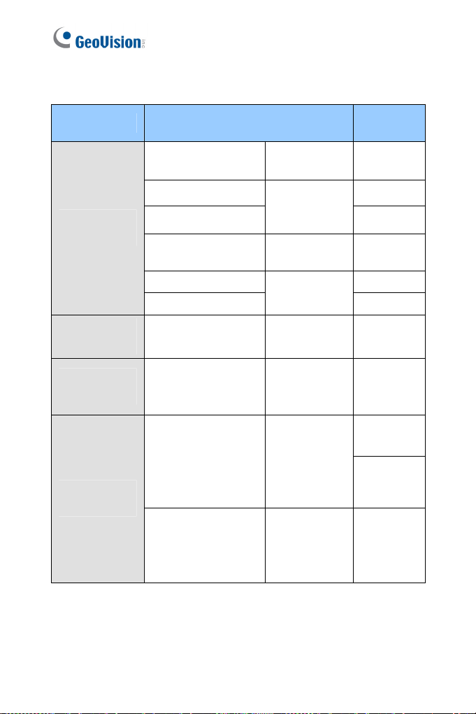
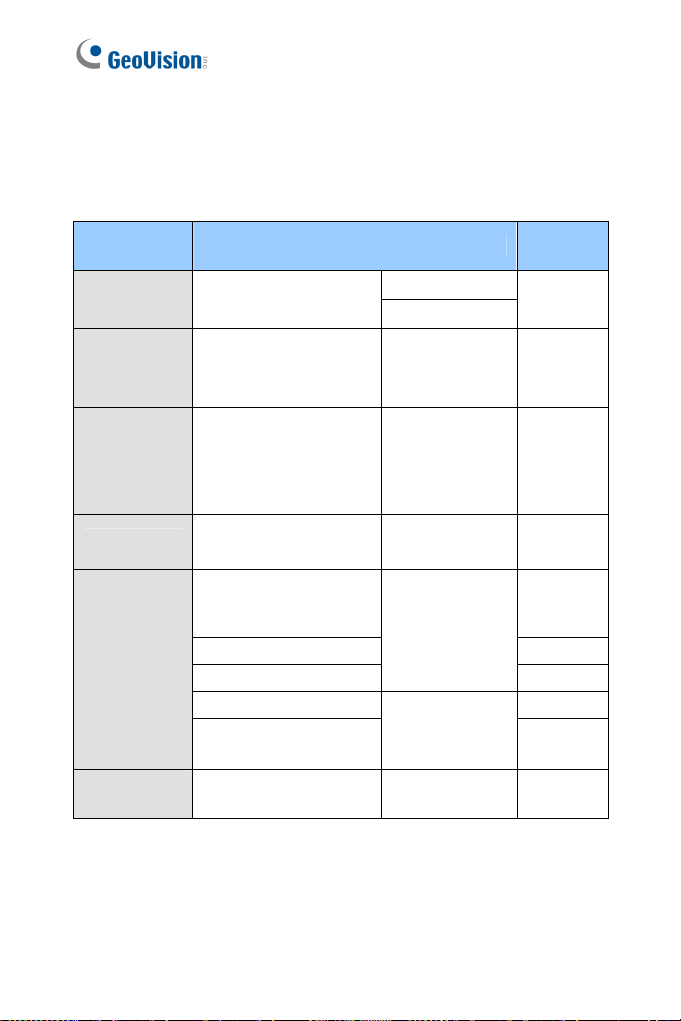
Model Model Number
GV-BX2400-0F ~ 2F
GV-BX2400-8F
-BX2600
GV
GV-BX1500-8F
-BX2500-8F
GV
-BX27 265
00-8F (H. ) GV
Box Camera
GV-BX34
GV
GV-BX47 .26
GV-BX5
GV-BX15
00-8F
-BX5300-8F
00-8F
7
00-8F
00-3V
GV-BX2500-3V
GV-BX3400-3V
GV-BX5300-6V
GV-BX2400-3V
GV-BX2400-4V
GV-BX2700-3V (H.265)
GV-BX4700-3V (H.265)
GV-BX5700-3V
GV-BX12201
(H
5)
26
(H.
5)
(H.265)
Fixed Lens
Varifocal
Lens
Fix
Varifocal
Lens, P-Iris
Varifocal
Lens,
DC-Iris
Varifocal
Lens, P-Iris
Varifocal
Lens
ed Lens
Firmware
Version
V3.12
V1.0
V3.12
06
V1.
V3.12
V1.06
V3.12
V3.12
V1.06
V1.06
V1.02
vii
Page 10
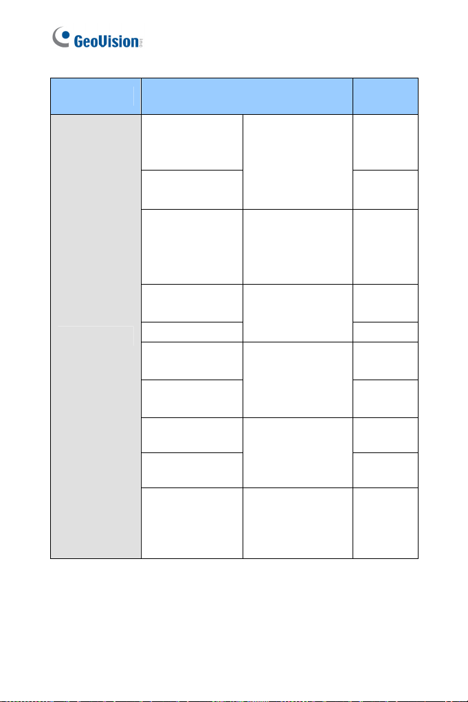
Model Model Number
GV-BX
2400-E
V-BX
G 5300-E
GV-BX
1500-E
IR Arctic Box
Camera
Target Box
era
Cam
Ultra Box
Camera
Mini Fixed
Dome
-BX3400-E
GV
GV-BX4700-E
)
(H.265 Lens
GV-BX2510-E
5310-E
GV-BX
GV-EBX1100 Se
X2100 Series
GV-EB
X1301 Series
GV-UB
X ries
GV-UB 2301 Se
GV-UBX3301 Series
GV-MFD1501 Series
GV-MFD2501 Series
GV-MFD2401 Series
GV-MFD3401 Series
GV-MFD5301 Series
GV-MFD2700 Series
(H.265)
GV-MFD4700 Series
(H.265)
ries
rifocal Lens
Va
otorized
M
rifocal
Va
Lens, P-Iris
Varifocal
, P-Iris
Motorized
rifocal Lens
Va
xed Lens
Fi
xed Lens
Fi
Fixed Lens
Fixed Lens
Firmware
Version
V3.12
V3.12
V3.12
V1.06
V3.12
V3.12
V1.10
V3.12
V3.12
V3.12
V1.06
viii
Page 11

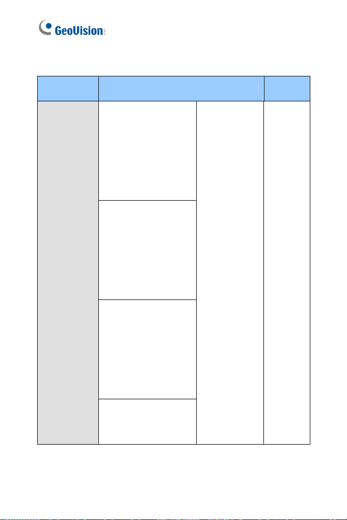
Model Model Number
GV-MDR220
GV-MDR320
GV-MD
Mini Fixed
gged D
Ru
Target Fixed
Dome
ome
R520
V-MD ries
R3400 SeG
GV-MDR5300 S
GV-MDR1500 S
GV-EFD2101
GV-EFD3101
FD5101
GV-E
eries
eries
ixed Lens
F
arifocal
V
Lens, P-Iris
Firmware
Version
V3.12
V3.12
V1.04
Target Mini
Fixed Dom
Target Mini
Fixed Dome
Target Mini
Fixed Rugged
Dome
Target Mini
Fixed Rugged
Dome
GV-EFD1100 Series
GV-EF 2100 Se
e
GV-E 4700 S
(H.2
GV-EFD2700-0F
GV-EFD2700-2F
GV-EDR1100 Series
GV-EDR2100 Series
GV-EDR4700 Series
GV‐EDR2700‐0F
GV-EDR2700-2F
D ries
FD rie
65)
e s
ixed Lens
F
F
ixed Lens
Fixed Lens
Fixed Lens
Fixed Lens V1.00
V1.10
V1.06
V1.00
V1.10
V1.06
ix
Page 12
Model Model Number
GV-BL1500
GV-BL2400
GV-B
L3400
GV-BL2500
GV-B 0
L121
GV-BL3410
GV-B
L5310
GV-B
L1501
-B
L2501 GV
GV-B
Bullet Cam
era
L3401
GV-B
L1511
GV-B 11
L25
GV-BL3411
GV-BL5311
GV-BL2511-E
GV-BL5311-E
GV-BL3700
(H.265)
GV-BL5700
(H.265)
Varifocal Lens
rized Varifocal
Moto
Lens
cal Lens,
Varifo
P-Iris
Moto
rized Varifocal
Lens, P-Iris
Motorized Varifocal
Lens, extreme
temperature
tolerance, P-Iris
Varifocal Lens, P-
Iris
Firmware
Version
V3.12
V3.12
V3.12
V3.12
V3.01
V3.12
V3.03
V3.12
V3.03
V1.03
x
Page 13

Model Model Number
GV-EB
L1100-1F
V-EBL
Target Bullet
Camera
Target Bullet
Camera
Target Bullet Motorized
Camera Varifocal Lens
Target Bullet
Camera
Target Bullet
Camera
G 1100-2F
-EBL2100-1F
GV
GV-EBL
2100-2F
xed Lens V1.10
Fi
GV-EBL2101 V1.04 Varifocal Lens
GV-EBL2111 V1.01
GV-EBL3101 Varifocal Lens V1.01
GV-EBL5101 Varifocal Lens V1.04
GV-EBL4702-1F
Target Bullet
Camera
Target Bullet
Camera
(H.265)
GV-EBL4702-2F
) (H.265
GV-EBL2702-1F
GV-EBL2702-2F
Fixed Lens V1.08
Fixed Lens V1.00
GV-UBL1211
Ultra Bullet
Camera
GV-UBL2411
GV-UBL3411
GV-UBL1511
GV-UBL2511
Motorized
Varifocal Lens
GV-UBL1301 Series
GV-UBL2401 Series
Fixed Lens V3.12
GV-UBL3401 Series
Firmware
Version
V3.12
Coming
xi
Page 14
Model Model Number
GV-VD120D
(IK10+, T
ransparent Cover)
D121D
GV-V
K10+, Smoked Cover)
(I
GV-VD12
(IK7, Tra
G
(I d Cover)
2D
nsparent Cover)
V-VD123D
K7, Smoke
GV-VD220D
nsparent Cover)
V-VD221D
moked Cover)
22D
nsparent Cover)
V-VD223D
Vandal Proof
e
IP Dom
(IK10+, Tra
G
(IK10+, S
GV-VD2
(IK7, Tra
G
K7, Smoked Cover)
(I
GV-VD320D
(IK10+, Transparent Cover)
GV-VD321D
(IK10+, Smoked Cover)
GV-VD322D
(IK7, Transparent Cover)
GV-VD323D
(IK7, Smoked Cover)
GV-VD1500
GV-VD2400
GV-VD2500
GV-VD3400
Firmware
Version
Varifocal Lens V3.12
xii
Page 15

Model Model Number
GV-VD1530
-VD
GV 2430
-VD
2530 GV
-VD3430
GV
GV-VD1540
GV-VD2440
GV-VD
2540
-VD
3440
GV
D
Vandal Proof
IP Dome
GV-V 5340
GV-VD2702 (H.265)
GV-VD4702 1.08 (H.265) V
GV-VD
GV-VD2712 )
GV-VD4711 (H.265)
GV-VD5711 (H.265)
GV-VD3700 (H.265) V1.03
GV-VD5700
IR Arctic
Vandal Proof
IP Dome
Target Vandal
Proof IP
Dome
GV-VD2540-E
GV-VD5340-E
GV-EVD2100
GV-EVD3100
GV-EVD5100
(H.265)
(H.265)
Varifocal Lens,
ower IR
high p
LEDs
rized Varifocal
Moto
Lens, high power
Ds
IR LE
cal Lens, P-
Varifo
Iris
Motorized Varifocal
Lens, P-Iris
rized Varifocal
Moto
Lens, P-Iris
Varifocal Lens, P-
Iris
Motorized Varifocal
Lens, high power
IR LEDs, extreme
temperatures
Varifocal Lens,
P-Iris
Firmware
Version
V3.12
V3.12
V1.05
V1.08 5702
V1.08 (H.265
V1.06
V1.04
V1.03
V3.12
V1.04
x
iii
Page 16
Model Model Number
PTZ Cam GV-PTZ010D
PT Cam
Advanced
Cube
Camera
Cube Ca
era
era
GV-PT130D
-CA120
-CA22
-CAW120
-CAW
-CB120
V-CB22
0D
220
0
GV-PT22
GV-PT320D
GV
GV 0
GV
GV
GV
G
NTSC
L
PA
Fi
xed Lens
ed Lens
Fix
xed Lens
Fi
Firmware
Version
V1.09
V3.12
V3.12
V2.14 mera
Fixed IP
Dome
Pinhole
Camera
xiv
GV-FD1500
GV-FD2500
GV-FD3400 V3.12
GV-FD5300
GV-FD3410 V3.12
GV-FD1510
GV-FD2510
GV-UNP2500 Fixed Lens V3.12
Varifocal
Lens
Motorized
Varifocal Lens
V3.12
V3.12
V3.12
Page 17

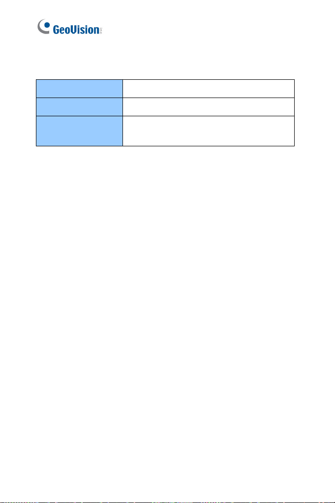
Nam n ing and Definitio
GV-DVR /
NVR
GV-VMS GeoVision Video Management System for IP cameras.
GeoVision Analog and Digital V
Software. The GV-DVR also refers to GV-Multicam
System, or GV-Hybrid DVR.
ideo Recording
xv
Page 18

Note for Connecting to GV-DVR /
NVR / VMS
The GV-IPCAM is designed to work with GV-DV
or digital video management system. Note the f
camera is connected to GV-DVR / NVR / V
1 By default, the images are recorded to the m
the GV-IPCAM (except GV-IR Arct
Series, which are not equipped with a memory card slot).
2 Once the camera is connected to the GV-DVR / NVR / VMS, the
resolution set on the GV-DVR / NVR / VMS will override the
resolution set on the camera’s Web interface. You can only change
the resolution settings through the Web interface when the
connection to the GV-DVR / NVR / VMS is interrupted.
R / NVR / VMS, a hybrid
ollowing when the
MS:
emory card inserted in
ic Box Camera and Target
xvi
Page 19

Note for Recording
1 By default, the images are recorded to t
the GV-IP Camera (except GV-IR Arctic Bo
Series, which are not equipped wit
r
e the Write recording data into lo
su
3.1.1 Video Settings) is enabled. If this opti
camera will stop recording to the memory c
accessed through Web browsers or
2 Mind the following when using a mem
Recorded data on the memory c
the data are accessed while the ca
shock, power interruption, memory ca
the memory c
guarantee is provided for such cause
ard reaches the end of its lifespan. No
The stored data can be lost if t
accessed for a long period of time. B
cally if you seldom access the memory card.
periodi
Memory cards are expendable and t
accordi
are used. Back up your data regularly and replace the
memory card annually.
o the conditions of the installed site and how they
ng t
he memory card inserted in
x Camera and Target
h a memory card slot). Make
cal storage option (see
on is disabled, the
ard while the live view is
other applications.
ory card for recording:
ard can be damaged or lost if
era is under physical
m
rd detachment or when
s.
he memory card is not
ck up your data
a
heir durability varies
Replace the memory card when its read/write speed is lower
than 6 MB/s or when the memory card is frequently
undetected by the camera.
3 It is recommended to use memory cards of the following setting
and specifications:
Apply a battery backup (UPS) to avoid power outage.
Use Micro SD card of MLC NAND flash, Class 10 for better
performance.
xv
i
i
Page 20

Note for GV-BX2600
Frame Rate
Mind the following restrictions, without regard t
camera images, when the GV-BX2600 cam
1 The codec MJPEG is not available in the m
2 Dual streaming is not support
3 Video analysis functions, including motio
4 TV-out is not supported.
5 The frame rate will be dropped to 30 fps during live streaming and
6 DR Pro function is not supported.
7 1
Browser
For the users of Microsoft Internet Explorer, version 11 or later is
required to perform the operations through Web browser.
Recording
o the resolution of the
era is set to 60 fps:
ain stream.
ed.
n detection, are not
supported.
recording when the camera starts moni
W
or 2 fps will be dropped on the point of obtaining snapshots in
JPEG format with the CGI command.
toring.
When GV-BX2600 uses Micro SD card or USB HDD for recording, the
camera must not have more than one connection to GeoVision or third-
party software.
xviii
Page 21

Note f
E
BL5101
When the resolution is set at 2592 x 1944:
1 If the camera is switched to sin
2 If the camera is switched to dual streams and Noise Reduction
3 As long as Noise Reduction is enabled, whether the camera is
or GV-EVD5100 / EFD5101 /
gl
e stream (while stream two is
deselected) and Noise Reduction is dis
can reach up to 30 FPS.
is disabled, the frame rate can reach up to 25 FPS.
switched to single stream or dual streams, the frame rate will
be 15 FPS.
abled, the frame rate
xix
Page 22

Chapter 1 Introduction
1
Introduction
The GV-IPCAM series offe
P
surveillance in various environmental conditions
I
1.1 System Requ
he c
To perform t
PC is in good network connection, and use one of the following web
browsers:
Microsoft Internet Explorer 8.0 or later
Google Chrome
Mozilla Firefox
Safari
Note:
1 For the users of Internet Explorer 8
require endix A.
2
For GV rnet Explorer 11 or later is required.
3 With no
A. M
B. only the Play function is available on the live view window
C. RTSP streaming must be kept as enabled. For more detail,
To access GV-BX12201 images, the PC spec should be met:
CPU Intel Core i5-4670, 3.40 GHz
ameras’ operations through Web browser, ensure your
d. For details, see App
-BX2600, Inte
n-IE browsers,
tion Detection, Tampering A
o larm, Visual Automation, Text
Overlay and two-way audio are not supported.
(Figure 19-3)
see 3.3.8 RTSP.
rs a comprehensive range of IP cameras for
.
irement
, additional settings are
Memory DDR3 8 GB RAM
On Board Graphics
Intel HD Graphics 4600 (Versions of driver
from year 2014 or later required)
1
Page 23
access GV -EVD3100 / 5100 and GV-
To -EFD3101 / 5101, GV
5101 ima pec should be met:
EBL ges, the PC s
CPU Intel Core i5-4670, 3.40 GHz
Memory DDR3 4 GB RAM
On Board Graphics
Intel HD Graphics 4600 (Versions of driver
from year 2014 or later required)
2
Page 24

2
Chapter 2 Getting Started
Getting Started
This section provides the initia
IPC
A
M.
l and basic configurations of the GV-
2.1 Accessing the Live View
When the camera is connected to a network with
be automatically assigned with a dynamic IP address. See 2.1.1
Checking the Dynamic IP Address to look up th
However, if you do not have a DHCP server on your network, access the
camera by its default IP address 192.168.0.10 and see 2.1.2 Configuring
the IP Address for more details.
Note: By default, GV-PTZ010D is assigned with the fixed IP address
192.168.0.10.
a DHCP
is IP address.
server, it will
3
Page 25
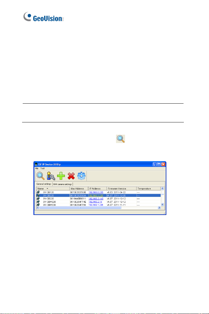
2.1.1 Checking the Dynamic IP Address
Fol and access the Web
low the steps below to look up the IP address
ce.
interfa
1. Install the GV-IP Device Utility program in
DVD.
cluded on the Software
Note: The PC inst
same LAN with the camera you wish to configure.
2. On the GV-IP Utility window, click the
IP devices connected in the s m LA Click the Name or Mac
Address sort.
alled with GV-IP Device Utility must be under the
button to search for the
a e N.
column to
Figure 2-1
4
Page 26
2
Getting Started
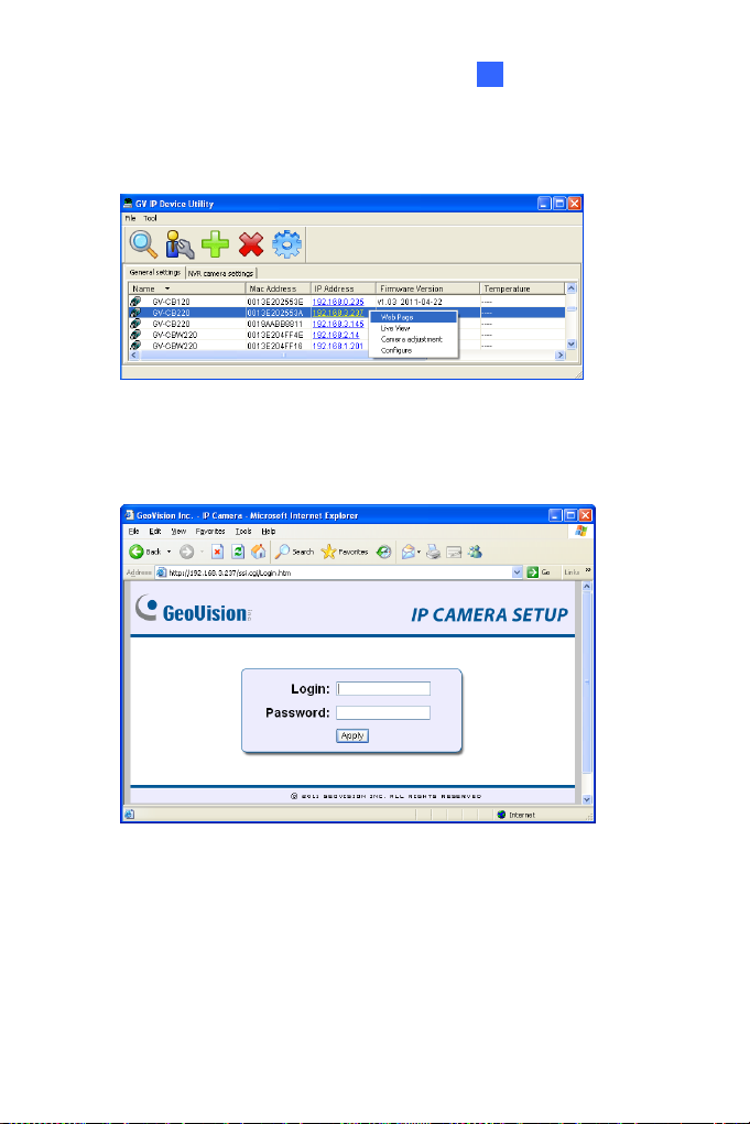
3.
Find the camera with its Mac Address, click on its IP address and
select Web Page.
Figure 2-2
4. The login page appears.
Figure 2-3
5. Type the default ID and password admin and click Apply to log in.
5
Page 27
2.1.2 Configuring the IP Address
Follow the steps below to configure the IP
1. ault IP address
Open your web browser, and type the def
http://192.168.0.10
2. In both Login and Password fields, type the default value admin.
Click Apply.
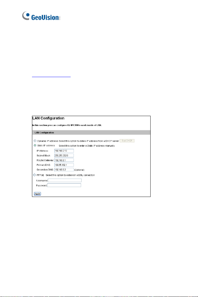
3. In the left menu, select Network and then LAN to begin the
network settings. This page appears.
.
address.
Figure 2-4
4. Select Dynamic IP address, Static IP address or PPPoE and
type the required network information.
5. Click Apply. The camera is now accessible by entering the
assigned IP address on the web browser.
6
Page 28

2
Getting Started
IMPORTANT:
1. If Dynamic IP Address or PPPoE is ena
which IP address the camera will get from
log in. If your camera is installed in the LA
Device Utility to look up its curren
Checking the Dynamic IP Address. If yo
dynamic IP address via PPPoE, use the d
obtain a domain name that is linked to th
address first. For details on D
4.7.1 LAN Configuration and 4.7.3 Advanced TCP/IP.
2. If Dynamic IP Address or PPPoE is enabled and you cannot
access the camera, you may have to reset it to the factory default
and then perform the network settings again.
To restore your camera to default settings, see Loading Factory
Default in the corresponding Hardware Manual.
ynamic IP Address and PPPoE, see
bled, you need to know
DHCP server or ISP to
N, use the GV-IP
t dynamic IP address. See 2.1.1
ur camera uses a public
ynamic DNS Service to
e camera’s changing IP
7
Page 29
2.1.3 Configuring the Wireless Conn
You may create wirel
Box Camera: GV-BX1200 series
series / 2500 series / 2700 series / 3400 s
5300 series / 5700 series
Wireless Advanced Cube Camera: GV-CA
Mini Fixed Dome: GV-MFD1501 series / 2401
/ 3401 series / 5301 series
1. To set up the wireless LAN for the first tim
a standard network cable
2. An IP address will be automatically assigned to the camera. Use
GV IP Device Utility to search for the device. For details, see 2.1.1
Checking the Dynamic IP Address.
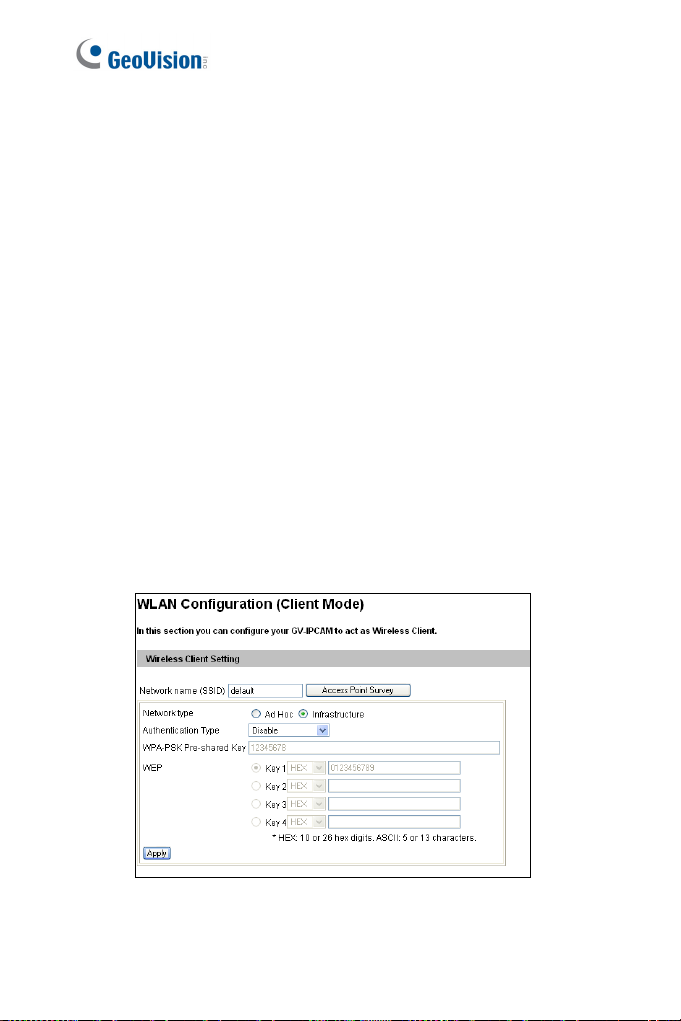
3. Configure the wireless settings.
A. On the Web interface, select Network, select Wireless and
Client Mode. This dialog box appears.
ess connection to the Internet for:
/ 1300 series / 1500 series / 2400
to the camera.
ection
es / 4700 series /
eri
W120/220
series / 2501 series
e
, power on and connect
Figure 2-5
8
Page 30

2
Getting Started
B.
Type the Network Name (SSID) or click the Access Point
Survey button to search and sele
Points/wireless stations.
C. Select
D. Select the Authentica
E. Type the WPA-PSK Pre-shared Key
F. Click Apply to save the configuration.
Note:
1. Your encryption settings must match those used by the Access
Points or wireless stations with which you want to associate.
2. When Ad Hoc is used, only WEP encryption is supported.
3. When you lose the wireless access, you can still access the unit by
connecting it to a LAN and using the GV IP Device Utility to search
for the device.
4. For detailed information on configuring the wireless LAN, see 4.7.2
Wireless Client Mode.
Ad-Hoc or Infrastructure for the Network type.
tion Type using the drop-down list. You
can also obtain this in
Survey button.
encryption setting for the Access P
formation by clicking the Access Point
ct for the available Access
or WEP depending on the
oint.
9
Page 31

4. Enable wireless LAN.
A. On the Web interface, select Network and LAN. This page
appears.
Figure 2-6
B. Select Wireless for Optional Network Type.
C. To use a dynamic IP address assigned by the DHCP server,
select Dynamic IP address. To use a fixed IP address,
select Static IP address and type the IP address information.
10
Page 32

2
Getting Started
5.
Click Apply. The Camera will start creating a wireless connection
to the access point.
Note: For GV-CAW1
connection is established.
6. Unplug the Ethernet cable.
20/220, the LAN LED turns blue when the
11
Page 33

2.2 Adjusting Image Clarity
Note the procedures described in this se
that allow manual focus adjustment. To adju
refer to Focus Adjustment in corresponding the
Cube Camera and
Adjustment in 3.2.2 The Control Panel on the Live View Window.
After you have connected your camera to the ne
below to adjust image clarity.
Advanced Cube Camera, refer to Camera
ction only apply to the cameras
st focus of a PTZ camera,
Hardware Manual; for
twork, follow the steps
1. Make sure you have installed the GV-IP De
i
nc
luded on the Software DV
Note: The PC installed with GV-IP Device Utility must be under the
same LAN with the camera you wish to configure.
2. On the GV-IP Utility w ndo , i the
IP
devices c d in the same LAN. Click the IP Address of the
camera you desire. A drop-down list appears.
onnecte
D.
w cl ck button to search for the
vice Utility program
i
12
Figure 2-7
Page 34

2
Getting Started
3.
Select Focus Value. The Login dialog box appears.
Figure 2-8
4. Type the user name and password of the camera selected. The
default is admin for both user name and password. This window
appears.
Figure 2-9
13
Page 35

5. For IK10+ models (GV-VD120D / 121D /
321
D / 1500 / 2400 / 2500 / 3400 / 1530 / 2430 / 2530 / 3430 /
4711 / 5711), hold the supplied Focus A
camera view. For details, see 2.2.1 Us
for details.
6. For Target Mini Fixed Dome and Target Mini Fixed Rugged
Dome, hold the camera cover close to the lens and use the
supplied focus adjustment tool for precise focus adjustment.
Figure 2-10
7. For Mini Fixed Dome and Mini Fixed Rugged Dome, hold the
camera cover close to the lens for precise focus adjustment. For
locations of adjustment screws and rings in each model, see 2.2.2
Locations of Adjustment Screws.
8. Adjust the Focus Screw and the Zoom Screw of the camera slowly
until the focus value reaches the maximum. For example, the
maximum focus value in Step 4 is 103. For locations of adjustment
screws in each model, see 2.2.2 Locations of Adjustment Screws.
220D / 221D / 320D /
djustment Cap over the
ing Focus Adjustment Cap
14
Page 36

2
Getting Started
Note:
1. Do not over tighten the screws. The s
tight
as your fingers can get them to be. Do not bother using any
tool to get them tighter. Doing so can damage the structure of
lens.
2. The maximum focus value may vary when the environment
changes.
crews only need to be as
15
Page 37

2.2.1 Using Focus Adjustment Cap
The Focus Adjustment Ca r IK10+ models (GV-
VD120D / 121D / 220D / 00 / 2400 / 2500 / 3400
/ 1530 / 2430 / 2530 / 343
p is only supplied fo
221D / 320D / 321D / 15
0 / 4711 / 5711).
Hold the Focus Adjustment
Cap on top of the camera view
and k
camera.
Do not leave a distance
between the Focus
Adjustment Cap and the
camera.
eep it close to the
16
Page 38

2.2.2 Locations of Adjustment Screws
Models Adjustment Screws
Box Camera
Bullet Camera
Vandal Proof IP Dome
2
Getting Started
Zoom Screw
Focus Screw
Zoom Screw
Focus Screw
Focus Screw
Zoom Screw
Fixed IP Dome
Focus Screw
Zoom Screw
17
Page 39

Models Adjustment Screws
GV-MFD1501 / 2401 /
3401 / 5301
GV-MDR220 / 320
GV-MDR1500 / 3400 /
5300
GV-VD3700 / 5700
Focus Ring
Focus Ring
Lens Screw
Focus Ring
18
Page 40

2
Getting Started
Note:
1. The adjustment screws of Box Camera m
models.
2. To focus GV-MFD and
slowly adjust the focus ring. Some models may need a T6 screw
driver to loosen the camera lens. If you have a problem of
obtaining this type of screw driver, please contact our overseas
offices for further assistance.
GV-MDR, loosen the lens screw first and
ay vary for different
19
Page 41

2.3 Configuring the Basics
Once the camera is properly installed, the following important features
an be
configured using the browser-based
c
discussed in the following sections in this m
Date and time adju
stment: s
ee 4
Login and privileged passwords: see 4.8.3
Network gateway: see 4.7 Network.
Camera image adjustment: see 3.2.2 The Control Panel of the Live
View Window
Video format, resolution and frame rate: see 4.1.1 Video Settings.
.
configuration page and are
anual:
.8.1 Date & Time Settings.
U
ser Account.
20
Page 42

3
Accessing the Camera
Chapter 3 Accessing the Camera
Two types of users are allowed to log on to the GV-IPCAM:
Ad
ini strator and Guest. The Administrator
m
system configurations, while the Guest can onl
(except the Camera Adjustm
ent settings) and network status.
3.1 Accessing Your Surveill
Once installed, your camera is accessible on a network. Follow these
steps to access your surveillance images:
1. Start your web browser.
2. Enter the IP address or the domain name of the camera in the
Location/Address field of your browser.
has full access to all
y access the live view
ance Images
3. Enter the login name and password.
Figure 3-1
The default login name and password for Administrator are
admin.
The default login name and password for Guest are guest.
21
Page 43

4. Click Apply. A video image, similar to the example on Figure 3-2,
is now displayed in your browser.
Note: To enable the updating of images in Internet Explorer, you must
set your browser to allow ActiveX Controls and perform a once-only
installation of GeoVision’s ActiveX component onto your computer.
22
Page 44

3
Accessing the Camera
3.2 Functions Featured on the Main Page
This section introduces the features of the Live View window and
Netw
ork S
tatus on th
both Adminis
Main Page
i
deo and Motion
▼ V
► Live View
► Camera
▼ Network
► Status
trator and Guest.
e main page. The two features are accessible by
of Guest Mode
Figure 3-2
The GV-IPCAM can process one video stream in two different codec
and image settings. In the Administrator mode, both streams are
available. Click Streaming 1 or Streaming 2 in the left menu to access
the live view. In the Guest mode, only one stream is available, as shown
in Figure 3-2.
23
Page 45

3.2.1 The Live View Window
Internet Explorer
When accessing the live view using Internet Explorer, the following
window appears.
8
9
10
11
1 2 3
24
5 6 7
4
Figure 3-3A
Page 46

3
Accessing the Camera
13
12
Figure 3-3B
25
Page 47

No. Name Function
1 Play Plays live video.
2 Stop . Stops playing video
Broadcasts to the surveillan
remote PC. Note th
for Ultra Bullet Camera
For Cube Camera an
3 Micropho
4 Speaker
5 Snapshot
6 File Save
7 Full Screen
ne
Camera, you can click
(from the pop-up men
switch between au
reception, where only one party can speak at a
time.
Transfers sounds o
remote PC. Note this
for Mini Fixed Rugge
Camera, Target Bull
Mini Fixed Rugged
Camera.
Takes a snapshot of live video.
--- See 3.2.3 Snapshot of Live Video.
Records live video to the local computer.
--- See 3.2.4 Video Recording.
Switches to full screen view. Right-click the
image to have these options: Snapshot, Full
Screen, Resolution, Zoom In, Zoom Out, PIP
and PAP.
--- See 3.2.5 Picture-in-Picture and Picture-
and-Picture View for PIP and PAP views
ce site from a
is function is not available
and Target Series.
d Advanced Cube
the Push to talk button
u) for the camera to
dio transmission and
f the surveillance site to a
function is not available
d Dome, Ultra Bullet
et Camera, and Target
Dome, and Pinhole
26
Page 48

No. Name Function
Displays the camera i
setti
ngs, audio data rate, I/O device status,
images captured upon
location of the came
adjust image
from the hard dr
Brings up thes
and Audio
Show Camera Name
--- See 3.2.6 Alarm N
3.2.7 Video and Audio
3.2.8 Remote Confi
3.2.9 Ca
3.2.11. Image Enhan
Enables the PTZ
PTZ. No
Camera and PT Cam
supported by GV-IP C
varifocal lens.
--- See The PTZ Control Panel (Hardware
Manual)
--- See 3.2.11 Visual PTZ
Enables the I/O Control Panel or the Visual
Automation. Note this function is only
supported by cameras with I/O function.
--- See 3.2.13 I/O Control.
Click to turn the Alarm LED on and/or adjust
the brightness sensitivity. Note this function is
only available for Advanced Cube Camera.
Show S
Menu
Panel
ystem
ntrol Panel
8 Control
9
10 PTZ Co
11 I/O Control
12 LED Control
3
Accessing the Camera
nformation, video
alarm, and GPS
ra. Also allows you to
quality and install the program
ive.
e functions: Alarm Notify, Video
Configurat
mera Name Display, and
te this function is supported by PTZ
ion, Remote Config,
and Image Enhance.
otification,
Configuration,
guration,
cement.
Control Panel or the Visual
era, and only partially
ameras with motorized
27
Page 49

No. Name Function
Click to sound the a
volume.
13 Alarm Speaker
To sound the alarm upon motion or tampering
events, see 4.3.9 Speaker for setup steps.
Note this function is only available for
Advanced Cube Camera.
larm and/or adjust its
28
Page 50

3
Accessing the Camera
Non-IE Browsers
When accessing the live view using Google Chrome, Firefox or Safari,
this window appears. Note the following functions are not supported on
non-IE browsers: Motion Detection, Tampering Alarm, Visual
Automation, Text Overlay and Two-Way Audio.
Figure 3-4
Note: Non-IE browsers do not support OCX plugin, so the
smoothness of the live view is obstructed. For users of non-IE
browsers, to enjoy smooth live view, download GV-WebViewer right
after you log on and you can also have access to the features of
Motion Detection, Tampering Alarm, Visual Automation, Text Overlay
and Two-Way Audio.
29
Page 51

3.2.2 The Control Panel of the Live View Window
To open the control panel of the Live View window, click the arrow
button on top of the window. You can access the following functions by
using the right and left arrow buttons on the control panel.
Click the right and left
Click the arrow button to
display the control panel.
arrow buttons to change
the page of the control
panel.
Figure 3-5
Tip: Administrator may also access live view and camera adjustment
settings using the GV-IP Device Utility:
30
Page 52

3
Accessing the Camera
[I
nformation] Displays the version of the camera, time of the local
computer, time of the camera (host time), the
the camera and the OCX registration path.
[Video] Displays the current video codec, resol
[Audio] Displays the audio data rates when the
speak
er devices are enabled.
[I/O Control] Note this function is only suppor
function. Provides a real-time graphic dis
status. You can force the output to be triggered by
icon.
[Alarm Notify] Displays the captured images by
moti
on detection. For this function to work, you have to configure the
Alarm Notification settings first. Se
[Camera Adjustment] Allows you to adjust th
Click Save to store the changes to the settings
only accessible for Administrator.
Brightness: Adjusts the brightness of th
Contrast: Adjusts the relative differences b
next.
Saturation: Adjusts the saturation of the
Sharpness: Adjusts the sharpness of the image
Gamma: Adjusts the relative proportions of bright and dark areas
White balance: The camera automatically adjusts the color to be
closest to the image you are viewing. You can choose one of the four
presets: Auto , Outdoor, Fluorescent, and Tungsten Lamp. You
can also choose Manual to adjust the white balance manually.
Flicker less: The camera automatically matches the frequency of
your camera’s image to the frequency of indoor light sources, e.g.
fluorescent lighting. You can also select 50 Hz or 60 Hz manually. If
these don’t match, faint light and dark bars may appear in your
e 3.2.6 Alarm Notification.
number of users logging in
ution and data rate.
microphone and
ted by cameras with I/O
play of the input and output
double-clicking its
sensor triggers and
e image quality settings.
. Note that this function is
e image.
etween one pixel and the
image.
31
Page 53

images. Check the power utility to determine which frequency is
used.
Note: For GV-BX4700 Series / 5700 Se
Flicker is listed in Video Signal Type, 4.1
Image Orientation: Changes the image o
View window.
Slowest Shutter Speed: Shutter speed co
lights enters the image sensor and direct
image presentation. A slow shutter spee
expo hat
sure t
obj
ects and bringing out background details,
speed lowers color and image clarity in order
The minimum shutter speed ranges from 1/
light conditions, a fast shutter speed will low
image c
shutter control or select Auto (High Speed Mode)
automatic shutter control.
D/
Select Auto for automatic switch betw
N:
mode depending on the amount of light detected. Select Black and
white to switch the camera to night mode. Select Color to switch the
camera to day mode. Sets the light sensor’s sensitivity of switching
between day mode and night mode. The value 10 is the most light-
sensitive. For details, see D/N, Special View Settings, 4.1.1 Video
Settings.
Denoise: Reduces image noise especially under low-light conditions.
The higher the denoise value, the stronger the effect.
creates a brighter overall image by blurring moving
larity. In this case, select the Auto option for automatic
ries, the function of
.1 Video Settings.
rientation on the Live
ntrols the amount of the
ly impacts the quality of
d allows higher light
and a faster shutter
to capture motions.
5 to 1/8000 sec. In low
er color quality and
for a faster
een day mode and night
Note: For GV-EVD5100, GV-EFD5101 and GV-EBL5101, refer to the
description of Noise Reduction in 4.1.1 Video Settings.
32
Page 54

3
Accessing the Camera
Wi
de Dynamic Range: adjusts and gener
the scene contains very bright and very dark a
Select Auto (Strong) to bring out details
scene, select Auto (Weak) to bring out fewe
areas and at the same
or select Auto (Normal) for a balanc
disable the function.
Defog: Select Auto to automatically enhanc
Select Close to disable the function.
Low Lux Enhancement: Select Auto for t
automatically enhance the live view under i
Close to disable the function. The default set
Super Low Lux is Close. The default setting f
Low Lux is Aut o.
Zoom: Click the Zoom In
the apparent distance of the scene. After zoo
focus the camera manually or automatical
Change and Focus Mode below.
Focus Change: Click the Focus In
o adj
ust the focus. To focus automatically
t
on.
butt
Focus Mode: Select Normal Scan, Regional Scan or Full Scan
and then click the Start
camera focus. The No can mode focuses the camera the
fastest. The Regional Scan mode focuses the area selected on the
live view. The Full Scan mode performs a detailed checkup and
applies the best focus.
Day Night Focus: Saves focus settings for day mode and night
mode. Select Au to to automatically focus. Select Close to disable
the Day Night Focus function. To configure fixed settings for day
mode and night mode, select Manual and follow the steps below:
time keep the bright areas from overexposure,
and Zoom Out
button to automatically adjust the
rmal S
ates clear live view when
reas at the same time.
of the dark areas of the
r details of the dark
ed effect. Select Close to
e the visibility of images.
he camera to
nsufficient light. Select
ting for cameras without
or cameras with Super
buttons to adjust
ming the camera, re-
ly. For details, see Focus
and Focus Out
, click the Auto Focus
buttons
33
Page 55

1. Make sure the D/N is in Auto mode fo
ocufollowing f s setting will be applied to
2. Adjust the focus using
buttons and/or the Focus Mode functio
3. Click Day Mode Save
depending on the current D/N mode.
Metering: Controls the camera’s expos
camera to adjust exposure based on the f
Regional Metering for the camera to adjust exposure of specified
zones. Draw directly on the live view and a block marked with “AE
(automatic exposure)” appears. You can establish up to 4 zones. To
remove the block, right-click the block and select Delete.
[Download] Allows you to install the programs from the hard drive.
the Focus In
or the Night Mode Save
r the best effect. The
the current D/N mode.
and Focus Out
n.
button
ure. Select Normal for the
ull live view. Select
34
Page 56

3
Accessing the Camera
Figure 3-6B
Figure 3-6C
Figure 3-6A
35
Page 57

Note:
1. For GV-PTZ010D, Brightness, Contrast
Sharpness, D/N, Slowest Shutter Speed
Range and Defog are not a
2. For GV-BX2600, Backlight Compensa
Range, Defog, Low Lux Enhancement, Denoise, Metering are
not available. The WDR setting for GV-B
page (see Fi
3. Zoom, Focus Change, Focus Mode and Day Night Focus
settings are only available for models with motorized varifocal
lens.
4. All Target Series support Denoise and Metering; for other
cameras, Denoise and Metering settings are only available for
firmware V2.14 or later.
gure 4-2A, 4.1.1 Video Settings).
vailable.
, Saturation,
, Wide Dynamic
tion, Wide Dynamic
X2600 is in Video Setting
36
Page 58

3
Accessing the Camera
3.2.3 Snapshot of Live Video
To take a snapshot of live video, follow these st
1.
Cl
ick the Snapsho
box appears.
2. Specify Save i
Save as Type
and date stamps on the image.
3. Click the Save button to save the image in the local computer.
t button (No. 5, Figure 3-3). The Save As dialog
n, type the File name, and select JPEG or BMP as
. You may also choose whether to display the name
3.2.4 Video Recording
eps:
You can record live video for a
computer.
ick the File Save button (No. 6, Figure 3-3). The Save As dialog
1. Cl
box appears.
2. Specify Save in, type the File name, and move the Time Period
slider to specify the time length of the video clip from 1 to 5 minutes.
3. Click the Save button to start recording.
4. To stop recording, click the Stop button (No. 2, Figure 3-3).
certain period of time to your local
37
Page 59

3.2.5 Picture-in-Picture and Picture-and-Picture View
The full screen mode provides two types of close-up views: Picture-in-
cture (PIP) and P
Pi
to provide clear and detailed images of the su
icture-and Picture (PAP). The two views are useful
rveillance area.
Picture-in-Picture View
With the Picture in Picture (PIP) view, you can crop the video to get a
close-up view or zoom in on the video.
Navigation box
Inset window
Figure 3-7
1. Right-click the live view and select PIP. An inset window appears.
2. Click the insert window. A navigation box appears.
3. Move the navigation box around in the inset window to have a
close-up view of the selected area.
4. To adjust the navigation box size, move the cursor to any of the
box corners, and enlarge or diminish the box.
5. To exit the PIP view, right-click the image and click PIP again.
38
Page 60

3
Accessing the Camera
Picture-and-Picture View
With the Picture and Picture (PAP) view, you can create a split video
effect with multiple close-up views on the image. A total of 7 close-up
views can be defined.
Figure 3-8
1.
Right-click the live view and select PAP. A r
windows appears at the bottom.
2. Draw a navigation box on the image, and th
immediately reflected in one inset window
boxes can be drawn on the image.
3. To adjust a navigation
corners, and enlarge or diminish the box.
4. To move a navigation box to another area on the image, drag it to
that area.
5. To add more navigation boxes, to show or hide navigation boxes or
to change the frame color of the navigation boxes, right-click the
image, select Mega Pixel Setting and click one of these options:
box size, move the cursor to any of the box
Enable Add-Focus-Area Mode: Allows the user to add more
navigation boxes on the image. This option is not available
when 7 navigation boxes have been drawn.
Display Focus Area of PAP Mode: Displays or hides the
navigation boxes on the image
ow of three inset
is selected area is
. Up to seven navigation
39
Page 61

Set Color of Focus Area: Changes the color of the box
frames.
6. To delete a navigation box, right-click the desired box, select
Focus Area of PAP Mode and click Delete.
7. To exit the PAP view, right-click the image and click PAP again.
40
Page 62

3
Accessing the Camera
3.2.6 Alarm Notification
After input triggers and motion detection, you can be alerted by a pop-up
live video and view up to four captured images.
Figure 3-9
To configure this function, click the Show System Menu button (No. 9,
Figure 3-3), and select Alarm Not if y. This dialog box appears.
Figure 3-10
Motion Notify: Once motion is detected, the captured images are
displayed on the control panel of the Live View window.
41
Page 63

I/O Alarm Notify: Once the input device is triggered, the captured
images are di
For this fun
device properly. See 4.2.1 Input Setting.
splayed on the control pane
ction to work, the Administrator needs to install the input
Alert Sound: Activates the computer al
triggered detection.
IE Window Pops up: The minimi
motion and input-triggered detection.
Auto Snapshot: The snapshot of live video is taken every 5
seconds on motion and input-triggered detection.
File Path: Assigns a file path to save the snapshots.
l of the Live View window.
m on motion and input-
ar
ve View window pops up on
zed Li
42
Page 64

3
Accessing the Camera
3.2.7 Video and Audio Configu
You can enable the micropho
communication and adjust the audio volume. To change audio
c
iguration, click the Show System Menu bu
onf
and select Video and Audio Configuration.
ne and speaker for two-way audio
ration
tton (No. 9, Figure 3-3),
Camera: Sets the number of frames to keep in live view buffer.
Keeping more frames for live view buffer can ensure a smooth live
view, but the live view will be delayed for the number of frames
specified.
Figure 3-11
43
Page 65

Audio Configure: You can enable the microphone and speaker,
and adjust the audio volume
Figure 3-12
44
Page 66

3
Accessing the Camera
3.2.8 Remote Configuration
You can upgrade firmware over the network. Click the Show System
Me
u button (No. 9, Figure 3-3), and select Rem
n
Remote Config dialog box will appear.
[Firmware Upgrade] In this tab, you can upgr
Internet. For details, see Advanced Applications
ote Config. The
ade the firmware over the
, Chapter 5.
3.2.9 Camera Nam
To display the streaming name on the image
Menu button
this function is not available for GV-VD3700 / 5700.
(No. 9, Figure 3-3), and select Show Camera Name. Note
e Display
, click the Show System
3.2.10 Image Enhancement
To enhance the i
Me
u button (No. 9, Figure 3-3), and select I
n
dialog box
mage quality of live video, click the Show System
mage Enhance. This
appears.
De-Interlace: Converts the interlaced video into non-interlaced
video.
De-Block: Removes the block-like artifacts from low-quality and
highly compressed video.
Enable DirectDraw: Activates the DirectDraw function.
Figure 3-13
45
Page 67

3.2.11 Visual PTZ
Note this feature is only available in PTZ C
The Visual PTZ pro
for easy and direct PTZ operation.
Activating Visual PTZ
vides two types of PTZ control panels on live images
a and PT Camera.
amer
Click the PTZ Control button
PTZ. Alternatively right-click here on the live view and select
Visual PTZ.
Figure 3-14
(No. 10, Figure 3-3) and select Visual
anyw
Visual PTZ
Control Panel
46
Page 68

3
Accessing the Camera
Th ual PTZ features:
e Vis Panel provides the following
. Name Description No
1 Zoom I
2 Zoom
3 Focus In
4 Focus Out
5 Home Brings the camera to the home point.
6 Auto Focus
7 Preset Go
8 Go Sequence
9 Auto Pan
Figure 3-15
n
Out
Shortens the appare
camera and the view.
Lengthens the apparent
camera and the vi
Adjusts the sharpness of the camera view.
Automatically adjusts the sharpness of the
camera view.
Starts a single movement in which the PTZ
Camera moves towards a point in live view.
Starts a series of movements in which the PTZ
Camera moves towards at least two Preset
points in live view.
Starts a horizontal movement of the PTZ
Camera in live view.
nt distance between the
distance between the
ew.
47
Page 69

Setting Visual PTZ Panel
Click the .button on the top left corner and select Visual PTZ, the
fo
llowing options will appear.
c
PTZ Control Type: Two types of visual PTZ
available.
Type 1: Appears only when a moveme
detected and disappears when it is sta
cursor in one of the eight directions, i.e
up, left down, right up and right dow
Click and hold onto the required level t
speed level is indicated at the top right
Type 2: Appears with a click on the live
with the second cli
directions, a 5-level arrow head appear
is away
from the visual PTZ control panel, the faster the
movement and vice versa. The speed level is indicated at the
top right corner of the live view.
ck. As the cursor points to one of the eight
Set Color: Changes the color of the arrow line and the speed
indicated at the top right corner of the live view. Alternatively, you
can right-click the live view (with Visual PTZ enabled). Three colors
are available: Red, Green and Blue.
Transparency: Changes the transparency level of the Visual PTZ
Control Panel. Ten levels range from 10% (fully transparent) to
100% (fully opaque).
ontrol panels are
nt of the cursor is
tic. When you place the
. up, down, left, right, left
n, a 5-level arrow appears.
o move the camera. The
corner of the live view.
view and disappears
s. The further the arrow
48
Page 70

3.2.12 Digital PTZ
3
Accessing the Camera
Note this function is only supported by GV-IPCA
V2.06
and the GV-IPCAM H.265.
This function allows non-PTZ c
live view.
1. Right-click the live view and select Digital PTZ. The live view is
labeled with “DPTZ” at the top left corner.
2. To zoom in / out, move the cursor to the live view and click the
corresponding buttons. To bring the view back to its default image,
click Home.
ameras to simulate PTZ movements on
Figure 3-16
M H.264 firmware
Figure 3-17
49
Page 71

3. To pan and tilt the view, zoom the image first and then click and
hold the arrow on the image. The arrow appears when you place
the cursor in one of the eight directions, i.e. up, down, left, right, left
up, left down, right up and right down.
Figure 3-18
4. To adjust the transparency level of the control panel, click the
green DPTZ button and select Transparency. Ten levels range
from 10% (fully transparent) to 100% (fully opaque) are available.
Note: The Focus In / Out and the speed level are not functional for
Digital PTZ.
50
Page 72

3
Accessing the Camera
3.2.13 I/O Control
Note this function is only supported by cameras w
The I/O Control window provides a real-time graphic display of camera
status, I/O status, and alarm events. Additionally, you can remotely force
output to be triggered.
ith I/O function.
Figure 3-19
To display the I/O control window, click the I/O Control button (No.
11, Figure 3-3) and select I/O Control.
The Alarm List is displayed in three levels. The first level indicates
date, the second indicates time, and the third indicates alarm ID.
Clicking the Reset button will clear the list.
To trigger an output device, highlight an output and then click the
Output button.
51
Page 73

3.2.14 Visual Automation
Note this function is only supported by camera
The Visual Automation allows you to change the current state of the
electronic device by simply clicking on its image, e.g. turning the light
ON. This feature is only available when the Visual Automation is set
ahead by the Administrator. For details, see 4.1.6 Visual Automation.
s with I/O function.
Figure 3-20
To access this feature, click the I/O Control button (No. 11, Figure 3-
3) and select Visual Automation.
To change the style of the set areas, click the green I/O button on the
top left corner. You will have these options:
Show All: Displays all set areas.
Rect Float: Embosses all set areas.
Set Color: Changes the frame color of all set areas
52
Page 74

3
Accessing the Camera
.15 Network Status
3.2
To view the network status, in the left menu, click Network and select
Status.
Figure 3-21
53
Page 75

Chapter 4 Administrator Mode
The Administrator can access the system configuration through the
network. Eight categories of configurations are involved in the system
configuration: Video and Motion, I/O Control or Digital I/O and PTZ,
Events and Alerts, Monitoring, Recording Schedule, Remote ViewLog,
Network and Management.
Figure 4-1
54
Page 76

4 4
Administrator Mode
Menu Options
List of
Find the topic of interest by referring to the corresponding section listed
below.
Note: The available options may vary among camera models and
firmware versions.
4.1.1 Video Settings
4.1.2 Motion Detection
4.1 Video and Motion
4.2 Video Analysis
4.3 Digital I/O and PTZ
4.4 Events and Alerts
4.1.3 Privacy Mask
4.1.4 Text Overlay
4.1.5 Tampering Alarm
4.1.6 Visual Automation
4.2.1 Motion Detection
4.2.2 Advanced Video Analysis
4.2.2.1 Intruder
4.2.2.2 People Count
4.2.2.3 Loitering
4.2.3 Unattended Object / Missing
Object Detection
4.2.4 Tampering Alarm
4.3.1 Input Settings
4.3.2 Output Settings
4.3.3 PTZ Settings
4.4.1 Email
4.4.2 FTP
4.4.3 Center V2
4.4.4 Vital Sign Monitor
4.4.5 Backup Center
4.4.6 Video Gateway/Recording Server
4.4.7 ViewLog Server
4.4.8 RTSP/ONVIF
4.4.9 Speaker
55
Page 77

4.5 Monitoring
4.6 Recording Schedule
4.7 Remote ViewLog
4.8 Network
4.9 Management
4.6.1 Camera
4.6.2 I/O Monitor
4.8.1 LAN
4.8.2 Wireless-Client Mode
4.8.3 Advanced TCP/IP
4.8.4 UMTS Settings
4.8.5 IP Filtering
4.8.6 SNMP Settings
4.9.1 Date and Time Settings
4.9.2 Storage Settings
4.9.3 User Account
4.9.4 Log Information
4.9.5 Tools
4.9.6 Language
56
Page 78

4 4
Administrator Mode
4.1 Video and Motion
The GV-IPCAM can simultaneously process one video source in two
different codec and resolutions. The dual-stream design benefits for lower
bandwidth environment, allowing Streaming 2 to be set with lower
resolution and codec for live streaming, and Streaming 1 set with highest
resolution and H.264 / H.265 for best recording quality. Two setting pages
Streaming 1 and Streaming 2 are provided for separate setup.
Comparison between Streaming 1 and Streaming 2:
Video Setting Options Streaming 1 Streaming 2
Watermark Setting
Audio in Source
Special View Setting
Video Resolution
Audio Settings Yes No
TV Out Yes No
Note:
1. Audio In Source is only available in GV-PTZ010D.
2. Audio Settings is not available for GV-PTZ010D.
3. TV Out is only available for Box Camera, IR Arctic Box Camera,
Vandal Proof IP Dome and Fixed IP Dome.
This section includes the video image settings and how the images can be
managed through Motion Detection, Privacy Mask, Text Overlay,
Tampering Alarm, and Visual Automation.
Yes
Yes. Different resolutions can be applied to
Streaming 1 and Streaming 2.
Not open for configuration.
But settings in Streaming 1
are automatically applied to
Streaming 2
57
Page 79

4.1.1 Video Settings
58
Figure 4-2A
Page 80

4 4
Administrator Mode
Figure 4-2B
59
Page 81

Figure 4-2C
[Name] Rename the video stream. To display the name of video stream on
the Live View window, see 3.2.9 Camera Name Display.
[Connection Template] Select the type of your network connection.
Unless you select Customized, this option will automatically bring up the
recommended video resolution, frame rate, bandwidth and GOP size.
[Video Signal Type] Select the video signal type, resolution and frame
rate. Select among H.265, H.264 or MJPEG as the codec type.
60
Page 82

4 4
Administrator Mode
Note t
hat for all the cameras (except GV-PTZ010D), the resolution options
available for sub stream vary with the resolution selected for its main
stream. For example, if a 4:3 resolution is selected for the main stream in
GV-EVD5100, three options, 960 x 720, 640 x 480 and 320 x 240 will be
available for its sub stream.
Flicker: Choose the Flicker Hz value between 60 Hz or 50 Hz. This
function is only supported by GV-BX4700 Series / 5700 Series.
Note:
1. For GV-BX4700 series, to reach 25 fps at 2560 x 1440, Flicker Hz
value must be set at 50 Hz.
2. The Hardware WDR Support option (see Figure 4-2A) is only
available for GV-BX2600. It produces clear live view when the
scene contains very bright and very dark areas at the same time.
This function is enabled by default. However, you will be prompted
to disable the function when the camera records up to 60 frames
per second.
For WDR Pro or WDR option of other cameras, see Camera
Adjustment in 3.2.2 The Control Panel on the Live View Window
to adjust the setting.
[Bandwidth Management] When using the H.264 / H.265 codec, it is
possible to control the bitrate, which in turn allows the amount of bandwidth
usage to be controlled.
VBR (Variable Bitrate): The quality of the video stream is kept as
constant as possible at the cost of a varying bitrate. The bandwidth is
much more efficiently used than a comparable CBR.
Set the image quality to one of the 5 standards: Standard, Fair,
Good, Great and Excellent.
61
Page 83

Maximal Bit Rate: When the actual bitrate exceeds the specified
Maximal Bit Rate, the system will automatically lower its bitrate so as
not to exceed it. Select one of the bitrates from the drop-down list or
select Auto if you do not want to enable this function. The default
maximal bitrate values are detailed as follows:
Camera Type Default Max. Bitrate of VBR
1.3 MP
2 MP
3 MP / 4 MP / 5 MP
8 MP / 12 MP
Note: For GV-BX2600, the default maximum bitrate for Stream 1 is set to
6 Mbit. When the video format of Stream 1 and 2 is set as MJPEG, the
options for bitrate setting will be hidden automatically.
CBR (Constant Bitrate): CBR is used to achieve a specific bitrate by
varying the quality of the H.264 / H.265 stream. Type the bitrate or
select one of the bitrates from the drop-down list.
Smart Streaming: When the option is enabled, the bitrates will be
automatically reduced in static scenes, significantly maximizing
bandwidth and lowering file size.
You can choose the image quality of Static Scene and Dynamic
Scene to one of the 5 standards: Standard, Fair, Good, Great and
Excellent. You can even choose the maximum bitrate to optimize the
bandwidth.
Stream 1 6 Mbit
Stream 2 4 Mbit
Stream 1 8 Mbit
Stream 2 4 Mbit
Stream 1
Stream 2
Stream 1
Stream 2
12 Mbit
16 Mbit
62
Page 84

4 4
Administrator Mode
Bitrate Reducti
value the more bitrates can be reduced in static scenes, thus saving
the recording size.
Note: It takes either GV-NVR V8.7 or GV-VMS V16.10.3.0 to enable Smart
Streaming. Refer to the technical notice for the models supporting the
feature:
http://pd.geovision.tw/technotice/IP_Camera/Summary_Smart_Streaming.pdf
[Region of Interest] Note this function is disabled by default and is not
supported by GV-BX2600 and Target Series. Sets ROI (clarity) to
specified regions on the live view for standalone GV-IP Cameras, GV-IP
Cameras connecting to GV-DVR / NVR / VMS or third-party software. A
total of 5 ROI can be set. This function is disabled by default.
on Level: The default value is 254. The bigger the
63
Page 85

Select Enable and click ROI Setting to configure:
1. On the popup window, use your mouse and draw directly on the live
view to specify a region.
Figure 4-3
2. To set up a region with enhanced clarity, select ROI, select High,
Medium or Low using the drop-down list and then drag on the
image to outline a region.
3. Click Apply to apply the configurations.
[GOP Structure and Length] Set the maximum number of seconds
between every key frame.
[Video Slice Mode] Note this function is only supported by firmware V2.12
or earlier and is not supported by Target Series and GV-IPCAM H.265.
Corrects the display mode of the camera when it is displayed on third-party
NVR/DVR software and the live view is incomplete or broken. Select
Single Slice or Multi Slice to display the live view. The default is Auto.
[H.264 Video Entropy Coding Setting] Note this function is not supported
by GV-IPCAM H.265, GV-BX12201 and Target Series. By default, the
entropy coding is set to CAVLC. To change it to CABAC, click and select
from the drop-down list.
64
Page 86

4 4
Administrator Mode
[Record
Settings] Note for GV-BX12201 firmware V1.02 or later and GV-
IPCAM H.265, see Recording Settings in 4.5 Monitoring Settings to adjust
the setting.
The alarm settings allow you to capture images before and/or after the
motion or I/O events happen.
Pre-alarm recording time: Activates video recording before an event
occurs. Set the recording time to 1 or 2 seconds. The recording is
saved in the buffer of the camera.
Post-alarm recording time: Activates video recording onto the
inserted memory card after an event occurs. Set the recording time
from 1 to 30 seconds.
Split-interval (Max. Video Clip): Sets the maximum time length of
each recorded file from 1 to 5 minutes.
Record Profile: Note this function is only available for firmware V2.14
or later. This setting is only applicable for recording to the camera’s
memory card. Select Performance to maximize the lifespan of the
memory card by restricting the maximum bit rate to 4 Mbit and
Sharpness value to 30. Select Quality to adopt your current settings.
Record audio: Activates audio recording when an event occurs.
Write recording data into local storage: Select this function for
uninterrupted recording to the memory card while the live view is
accessed through the Web interface or other applications. This option
is enabled by default.
IMPORTANT: To ensure the quality of simultaneous recording and live
view access, make sure you connect no more than two connections to
the camera using Web interface or any other applications.
65
Page 87

[Text Overlay Settings] Displays camera name, date, and/or time on the
live view and recorded videos when viewing through GeoVision software.
Camera Name: Type the camera name.
Overlay with: Select one or more of the options below to be overlaid
on the live view and recorded videos.
Camera Name
Date
System Time
Name of the Associated Digital Input: Note this option is only
supported by cameras with I/O function.
[Text Overlay Settings (OSD)] Note this function is not supported by GV-
BX2600.
Displays camera name, date, and/or time on the live view and recorded
videos when viewing through GeoVision software and third-party software
through ONVIF and RTSP.
Name: Type the camera name.
Font Size: Select the font size using the drop-down list.
Overlay with: Select one or more of the options below to be overlaid
on the live view and recorded videos. Use the drop-down list to select
the display position.
Camera Name
Date
System Time
[Watermark Setting] Note this function is not supported for Target Series.
Enable this option to watermark all recordings. The watermark allows you
to verify whether the video has been tampered while it was recorded. See
6.4 Verifying Watermark.
66
Page 88

4 4
Administrator Mode
[A
udio In Source] Note this function is only available in GV-PTZ010D
which contain a built-in microphone and also allow you to install an external
microphone.
Built-in Microphone: Enable the built-in microphone to record
sounds. By default the option is enabled.
External Microphone: Enable the externally connected microphone
to record sounds.
[TV Out] Note this function is only available for the camera with TV-out
connector. Select the signal format of the Video Output on the camera as
either NTSC or PAL.
[Audio Settings] Enable Noise Reduction to reduce the background
noise in the audio file. All H.265 cameras applying firmware V1.02 or later
support this function.
[LED Control] Note this function is not available for GV-PTZ010D.
Ready LED: Select Disable if you do not wish to use the Status LED.
LAN LED, WAN LED, Monitoring LED: Note this option is only
available in Advanced Cube Camera. Select Disable if you do not
wish to use the LEDs. For details on LED status, see Overview in the
corresponding Hardware Manual.
Al arm LED: Sets the white illumination LED in Advanced Cube
Camera. The LED is enabled by default.
Auto: Select Auto for the white illumination LED to illuminate the
scene automatically when the PIR sensor detects any motion
within 5 meters.
67
Page 89

Sensitivity: Set the sensitivity for low light detection. The higher
the value, the easier the white illumination LED is to be triggered.
The default value is 5.
The Interval between triggering: Select the duration for the white
illumination LED to light up at full intensity. If a motion persists
over the specified period, the white illumination LED will light up
with less intensity. This option is designed to keep the camera
temperature within its precautious range. The default value is 60
seconds.
Off: Select to disable the white illumination LED.
[Special View Setting] Note this function is not available for GV-BX2600.
D/N: Sets the sensitivity of day-night mode switch. The higher the
sensitivity value, the more sensitive the switch is from day mode to
night mode. The default value is 5.
Auto: Select Auto for the camera to detect the amount of light
present and automatically switch to monochrome in a poorly-lit
scene. Move the slider to adjust the sensitivity level from 0 to 10.
Black and White: Select this option for the live view to be in
monochrome.
Color: Select this option for the live view to be in color.
Triggered by Input: For GV-BX12201 firmware V1.02 or later,
select this option to switch between day mode and night mode
once the input device (e.g. sensor or button) is triggered.
Schedule: For GV-BX12201 firmware V1.02 or later, select this
option to determine specific period(s) of time when day mode is
activated. See 4.6.1 Recording Schedule Settings for the details
on the setting of the schedule.
68
Page 90

4 4
Administrator Mode
IR Check Function: Note this option is only available for Box
Camera (except GV-BX2600). This function determines whether the
surveillance area is illuminated by an externally installed infrared
illuminator.
Off: The default setting. The infrared illuminator will be constantly
off. It is advisable to enable this option when the color temperature
of outdoor lighting is 6000 K or above.
On: The infrared illuminator will be constantly on.
Trigger by Input / Trigger IR by D/N: Select this option for the
infrared illuminator to turn on under low light and turn off under
sufficient light.
Note:
1. If an infrared illuminator is installed for outdoor surveillance, it is
suggested to use the Trigger by Input or the Trigger IR by D/N
function to avoid incorrect judgment of lighting and hence the action
of the IR cut filter. See Infrared Illuminators in the Hardware
Manual.
2. If you select Trigger by Input / Trigger IR by D/N option, make
sure you have set D/N as Auto and configured its sensitivity level.
Iris Type: Note this function is not supported for the camera with fixed
lens or fixed iris. This field shows the iris type (DC-Iris or P-Iris) of
your GV-IP Camera.
Auto Iris: The option is designed for auto iris lens (DC-Iris or P-
Iris). Enable the auto iris function when the scene appears fuzzy
and the Flicker Less function does not help to improve the
situation.
BLC: Note this function is not supported by GV-BX2600. Select On to
enable Backlight Compensation (BLC). This function is used to adjust
the color intensity of scenes with strong light at the background.
69
Page 91

Note: To access the BLC function in PTZ camera, see Other, Image
Settings in the Hardware Manual.
IR Light: Note this function is only available for Target Series, Ultra
Box Camera, IR Arctic Box Camera, Bullet Camera, Ultra Bullet
Camera, PT Camera, Vandal Proof IP Dome and Fixed IP Dome.
Select Auto for automatic switch between day mode and night mode
depending on the amount of light detected. Select Off to completely
disable IR LEDs.
Noise Reduction: Note this function is only supported by GV-
EVD5100, GV-EFD5101 and GV-EBL5101. Reduces image noise
especially under low-light conditions.
Note: When the Noise Reduction is enabled, the frame rate will be
affected. For details see Note for GV-EVD5100 / EFD5101 / EBL5101 at
the beginning of the manual.
70
Page 92

4 4
Administrator Mode
4.1.2 Motion Detection
Motion detection is disabled by default except for GV-PTZ010D.
Note: GV-BX2600 has its independent motion detection setting. For
details, see 4.2 Video Analysis.
Motion detection is used to generate an alarm whenever movement occurs
in the video image. You can configure up to 8 areas with different
sensitivity values for motion detection. Set up at least one area to enable
this function.
71
Page 93

Figure 4-4
1. Select the desired sensitivity by moving the slider. There are ten
values. The higher the value, the more sensitive the camera is to
motion.
2. Drag an area on the image. Click Add when you are prompted to
confirm the setting.
3. To create several areas with different sensitivity values, repeat steps
1 and 2.
4. Click Save to save the above settings.
5. Click Reset to delete all the selected areas.
72
Page 94

4 4
Administrator Mode
6.
If you want to detect motion using the PIR sensor (for Advanced
Cube Camera only), select Use PIR to detect motion.
7. If you want to ignore environmental changes such as rain or snow,
select Ignore environmental changes.
8. The Noise Tolerance function is enabled by default. It ignores video
noise when the light intensity changes.
9. To set a period of time before a motion is to be detected, select Set
time interval. The choices available range from 0-3 second(s).
10. To set a period of time for a motion to last, select Set duration. The
choices available range from 1-5 second(s).
11. If you want to trigger the alarm output when motion is detected, select
Output 1 and click the Apply button. To activate the output settings,
you must also start Input monitoring manually or by schedule. For
related settings, see 4.5 Monitoring.
Note: Set time interval and Set duration are only supported by GV-
BX12201 firmware V1.02 or later.
73
Page 95

4.1.3 Privacy Mask
The Privacy Mask function is used to block out sensitive areas on live view
and recorded clips for cameras connecting to GeoVision software. This
feature is ideal for locations with displays, keyboard sequences (e.g.
passwords), and for anywhere else you don’t want sensitive information
visible.
Figure 4-5
1. Select the Enable option.
2. Drag the area(s) where you want to block out on the image. Click Ad d
when you are prompted to confirm the setting.
3. Click the Save button to save all the settings.
74
Page 96

4 4
Administrator Mode
4.1.4 Text Overlay
The Text Overlay allows you to overlay any text in any place on the camera
view. Up to 16 text messages can be created on one camera view. The
overlaid text will be saved in the recordings.
Figure 4-6
1. Select the font, font style and font size in a pop-up window.
2. Select the Enable option.
3. Click any place on the image. This dialog box appears.
Figure 4-7
4. Type the desired text, and click OK. The text is overlaid on the image.
5. Drag the overlaid text to a desired place on the image.
75
Page 97

6. Click Set Font to modify the font settings.
7. Click Save to apply the settings, or click Load (Undo) to revert to the
last saved setting.
8. Click Preview to see how the text will appear on the image. Click
Close to end the preview.
76
Page 98

4 4
Administrator Mode
4.1.5 Tampering Alarm
Note this function is not available for PTZ Camera and PT Camera.
Tampering Alarm is used to detect whether a camera is being physically
tampered. An alarm can be generated when the camera is moved, covered
up, or out of focus. The alarm types include triggered the output device, e-
mail alert and notifying the connected GV-Center V2, GV-Vital Sign Monitor
and GV-DVR / NVR / VMS.
Note:
1. This function is not available for PTZ Camera and PT Camera.
2. GV-BX2600 has its independent Tampering Alarm setting. For
details, see 4.2 Video Analysis.
To establish the tampering alarm, set up at lest one alarm type:
To trigger the output device when a tampering event occurs, enable
the output setting and select Tampering Alarm. See 4.3.2 Output
Settings.
To trigger the e-mail alert when a tampering event occurs, enable the
e-mail setting and select Tampering Alarm. See 4.4.1 E-Mail.
To notify GV-Center V2, GV-Vital Sign Monitor and GV-DVR / NVR /
VMS when a tampering event occurs, enable the connection to these
systems. See 4.4.3 Center V2, 4.4.4 Vital Sign Monitor, 7.1 Setting up
an IP Camera on GV-DVR / NVR, and 7.2 Setting Up IP Cameras on
GV-VMS.
77
Page 99

Figure 4-8
To configure the tampering alarm:
1. Select the Enable option.
2. If you want the camera to ignore any movement or scene change in
certain areas, click the
3. Select the desired detection sensitivity by moving the slider. The
higher the value, the more sensitive the camera is to scene changes.
4. In the Tolerance Time of Alarm field, specify the time length allowed
for scene changes before an alarm is generated.
5. In the Duration of Alarm field, specify the duration of the alarm after
which the triggered output device will be turned off.
button to drag areas on the camera view.
78
Page 100

4 4
Administrator Mode
6.
To trigger an alarm when the scene turns dark, e.g. when the lens of
camera is covered, make sure the Alarm for Dark Images option is
enabled. By default, this function is enabled.
7. Click Apply to save all the settings.
8. Start monitoring to enable the function. To have output alarm, it is
required to start Input monitoring. See 4.5 Monitoring.
When the camera has been tampered, the output device can be activated.
To turn off the output device immediately, return to this setting page, and
click Restart Detection.
79
 Loading...