

Page 1
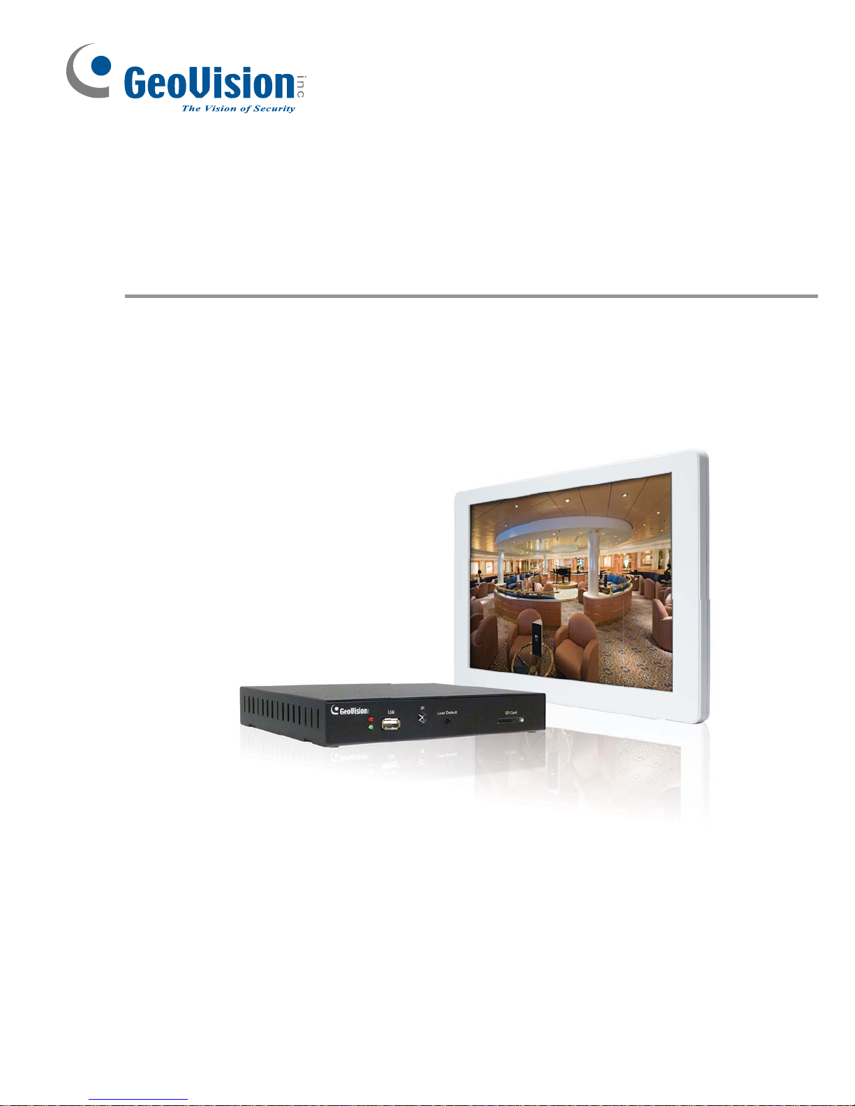
GV-IP Decoder Box and GV-Pad
User’s Manual V1.01
DBV101-A-EN
Before attempting to connect or operate this product, please
read these instructions carefully and save this manual for future use.
Page 2
© 2012 GeoVision, Inc. All rights reserved.
Under the copyright laws, this manual may not be copied, in whole or in part,
without the written consent of GeoVision.
Every effort has been made to ensure that the information in this manual is
accurate. GeoVision, Inc. makes no expressed or implied warranty of any kind
and assumes no responsibility for errors or omissions. No liability is assumed
for incidental or consequential damages arising from the use of the information
or products contained herein. Features and specifications are subject to
change without notice. Note: no SD card slot or local storage function for
Argentina.
GeoVision, Inc.
9F, No. 246, Sec. 1, Neihu Rd.,
Neihu District, Taipei, Taiwan
Tel: +886-2-8797-8377
Fax: +886-2-8797-8335
http://www.geovision.com.tw
Trademarks used in this manual: GeoVision, the GeoVision logo and GV
series products are trademarks of GeoVision, Inc. Windows and Windows XP
are registered trademarks of Microsoft Corporation.
January 2012
Page 3

i
Content
GV-IP Decoder Box
Chapter 1 Introduction ........................................................................................................1
1.1 Features .....................................................................................................................2
1.2 Compatible Devices ...................................................................................................3
1.3 Packing List................................................................................................................4
1.4 Optional Accessories..................................................................................................4
1.5 Overview ....................................................................................................................5
1.5.1 Front View ...................................................................................................5
1.5.2 Rear View....................................................................................................6
1.6 The IR Remote Control ..............................................................................................7
Chapter 2 Getting Started ...................................................................................................9
2.1 Installing the GV-IP Decoder Box...............................................................................9
2.2 Connecting the GV-IP Decoder Box......................................................................... 11
2.3 Configuring the IP Address, ID and Password .........................................................12
2.4 Displaying Channels from GV IP Devices................................................................15
2.5 Displaying Channels Using GV IP Device Utility ......................................................17
2.6 Displaying Channels from GV-System .....................................................................22
2.7 Taking a Snapshot.................................................................................................... 28
2.8 Pausing the Looped View......................................................................................... 29
2.9 Controlling PTZ Cameras.........................................................................................30
Chapter 3 System Setup ...................................................................................................31
3.1 Searching IP Devices ...............................................................................................32
3.2 Setting the Network ..................................................................................................33
3.3 Configuring the Play Mode .......................................................................................34
3.4 Adding a GV IP Device.............................................................................................35
3.5 Configuring the Account, Storage and Output Type .................................................36
3.6 Upgrading the Firmware...........................................................................................37
3.6.1 Updating Firmware through USB Drive or SD Card ..................................37
3.6.2 Updating Firmware through GV IP Device Utility ......................................38
Specifications .......................................................................................................................40
Chapter 4 Introduction ......................................................................................................42
4.1 Features ...................................................................................................................43
4.2 Compatible Devices .................................................................................................43
4.3 Packing List ..............................................................................................................43
4.4 Optional Accessories................................................................................................44
4.5 Overview ..................................................................................................................45
Page 4

ii
4.5.1 Right Panel View.......................................................................................45
4.5.2 Left Panel View .........................................................................................46
4.6 The IR Remote Control ............................................................................................47
Chapter 5 Getting Started .................................................................................................48
5.1 Installing the GV-Pad................................................................................................48
5.2 Connecting the GV-Pad............................................................................................49
5.3 Configuring the Basics .............................................................................................50
5.4 Managing the GV-Pad..............................................................................................51
Chapter 6 System Setup ...................................................................................................52
Specifications .......................................................................................................................53
Page 5
iii
GV-IP Decoder Box
Page 6

Page 7
1
Chapter 1 Introduction
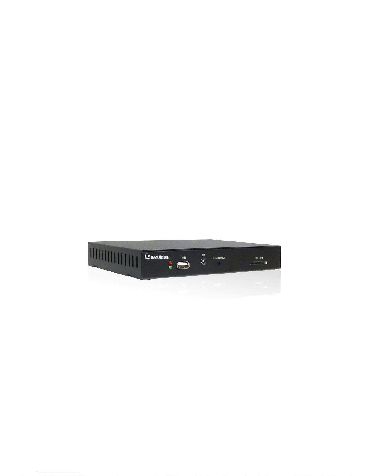
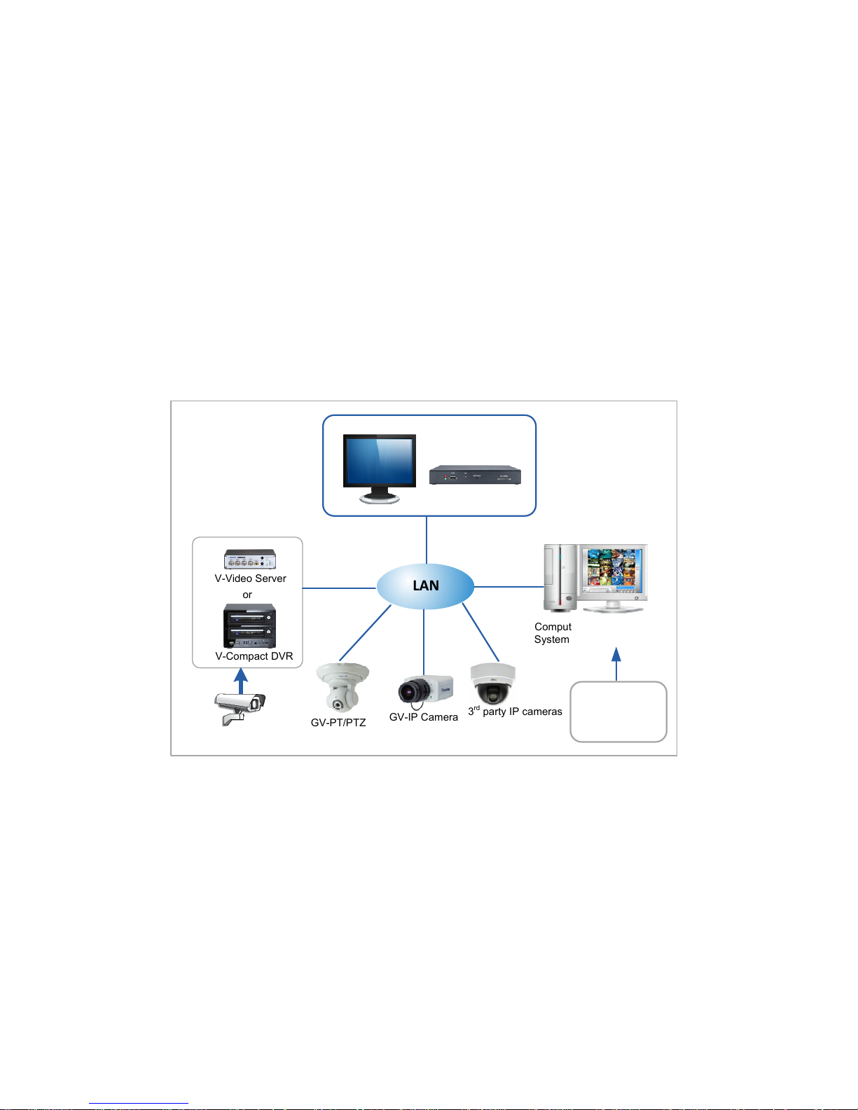
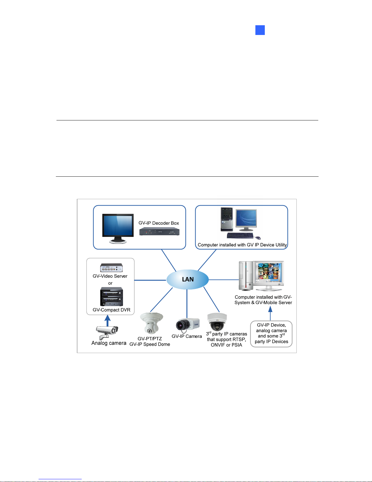
The GV-IP Decoder Box is designed to decode incoming IP streams from GeoVision and
third-party IP devices, and displaying them on a digital or an analog monitor. To be used with
only a monitor, the GV-IP Decoder Box provides a cost-effective solution for video
surveillance as opposed to the traditional DVR and PC setup. The security administrator can
monitor channels, take snapshots of critical moments, and pause at a channel when events
occur, all through the supplied remote control. Connected GeoVision PTZ cameras such as
GV-PTZ010D, GV-PT110D and GV-IP Speed Dome can also be controlled through
GV-Joystick.
LAN
GV-IP Decoder Box
Computer installed with GVSystem & GV-Mobile Server
GV-PT/PTZ
GV-IP Speed Dome
GV-IP Camera
3rdparty IP cameras
that support RTSP,
ONVIF or PSIA
GV-Compact DVR
GV-Video Server
Analog camera
or
GV-IP Device,
analog camera
and some 3
rd
party IP Devices
Figure 1-1
Page 8

2
1.1 Features
z Decode video streams in H.264 codec at a maximum frame rate of the IP device
z Decode up to 5 megapixel IP cameras
z Decode up to 64 IP streams
z Support for 3
rd
party IP cameras that adhere to RTSP, ONVIF or PSIA
z Support for 10/100 Ethernet over LAN
z Support for single and sequential display
z VGA and High Definition Video outputs
z Video output resolution up to 1080p
z Support for GV-Joystick control of GV PTZ cameras (GV-PTZ010D and GV-PT110D)
and GV-IP Speed Dome
z Support for remote firmware upgrade, IP address configuration and addition of new
channel
z Display of Matrix view through GV-Mobile Server
z IR remote control
z SD card and USB drive for snapshot storage and firmware upgrade
Page 9
Introduction
3
1
1.2 Compatible Devices
The GV-IP Decoder Box is compatible with:
1. Most GeoVision IP devices (of the indicated firmware versions) using H.264 codec, and
2. Third-party IP devices that support H.264 and adhere to RTSP, ONVIF or PSIA.
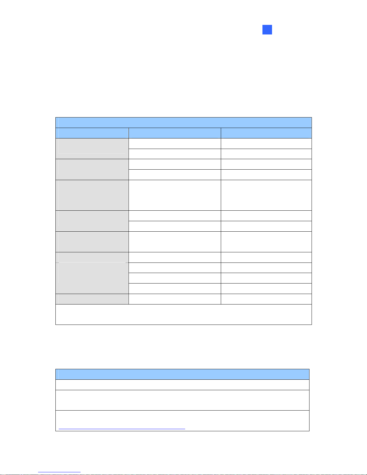
Supported GeoVision IP Devices
Device Type Models Firmware Versions
GV-BX110D V1.08 or later
Box Camera
All models (except GV-BX110D) V1.06 or later
GV-BL110D V1.08 or later
Bullet Camera
All models (except GV-BL110D) V1.06 or later
Cube Camera
Fixed Dome
Vandal Proof IP Dome
All models V1.06 or later
GV-MFD110 V1.08 or later
Mini Fixed Dome
All models (except GV-MFD110) V1.06 or later
PT Camera
PTZ Camera
GV-PT110D
GV-PTZ010D
V1.08 or later
Speed Dome All models V1.02 or later
GV-VS04H V1.04 or later
GV-VS11 V1.0 or later
Video Server
GV-VS12 V1.05 or later
Compact DVR GV-Compact DVR V3 series only V1.0 or later
IMPORTANT: The connected GeoVision and third-party channels must be set with H.264 codec to be
compatible.
To decode and display non-H.264 IP channels or analog channels, connect the devices to
GV-System and access them through GV-Mobile Server. The supported devices are listed
below.
Supported Devices Connected to GV-System
Analog cameras
All models of GeoVision IP cameras, GV-Video Server, GV-Compact DVR, GV-IP Speed
Dome, GV-Smart Box and GV-DSP LPR
11 brands of third-party IP cameras. For detail, see
http://www.geovision.com.tw/english/4_21.asp
Page 10
4
1.3 Packing List
1. GV-IP Decoder Box × 1
2. IR remote control × 1
3. AC/DC adapter × 1 (12 V, 3 A, 36 W)
4. Power cord x 1
5. Software DVD x 1
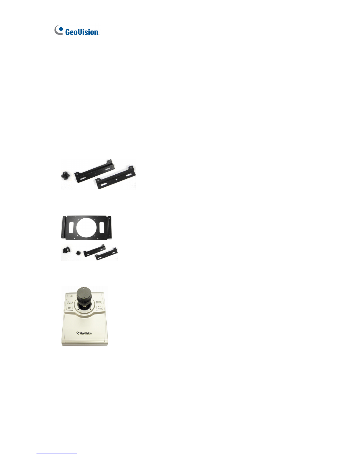
1.4 Optional Accessories
1. Wall mount kit:
z L-type brackets x 2
z Small screws x 4
2. VESA monitor mount kit:
z VESA monitor mount bracket x 1
z L-type brackets x 2
z Large screws x 4
z Small screws x 8
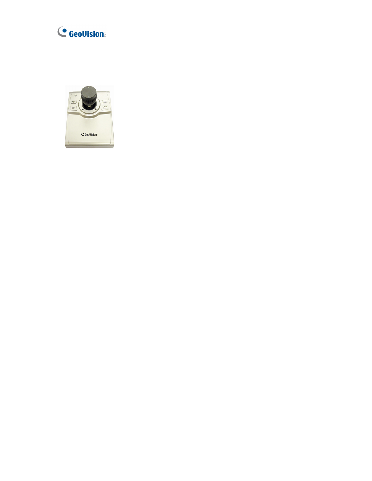
3. GV-Joystick
z GV-Joystick x 1
z USB Type A to Type B Cable x 1
z GV-Joystick User’s Manual x 1
Page 11
Introduction
5
1
1.5 Overview
This section identifies the components of the GV-IP Decoder Box.
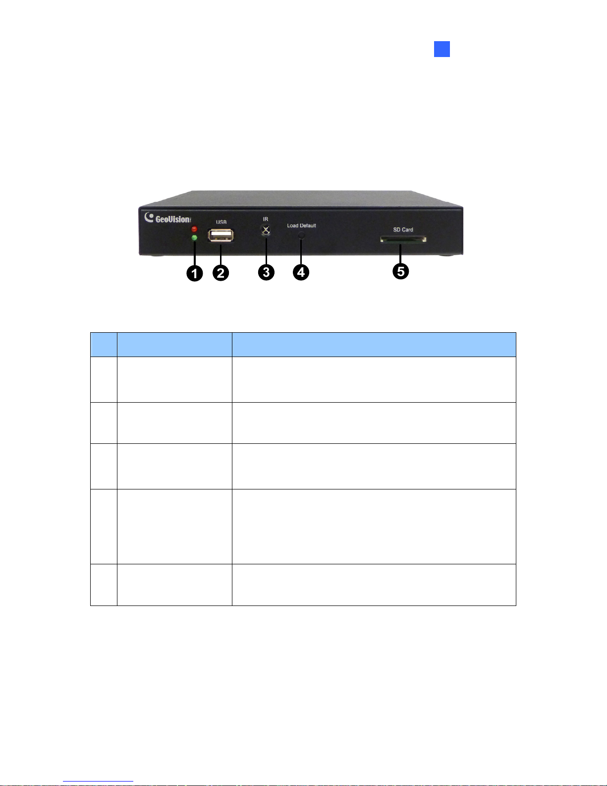
1.5.1 Front View
Figure 1-2
No. Name Function
1 LED Indicators
The green LED indicates the system is ready for use.
The red LED indicates the power is supplied.
2 USB
Connect to a GV-Joystick, or to a USB storage device for
local storage of snapshot and firmware upgrade.
3 IR
Built-in IR receiver to receive the IR signals from the IR
remote control.
4 Default
Reset the GV-IP Decoder Box to the default factory settings.
Use a pin to press the default button until the green LED
fades. This will take about 10 seconds. The system will then
reset and reboot itself shortly.
5 SD Card Slot
Connect to an SD card for local storage of snapshot and
firmware upgrade.
Page 12
6
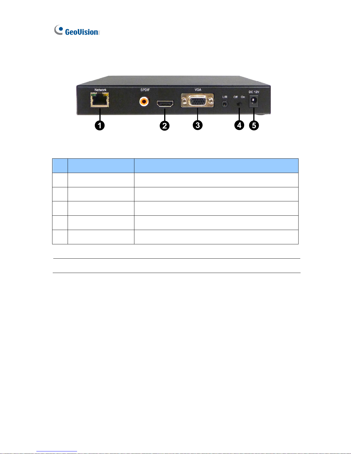
1.5.2 Rear View
Figure 1-3
No. Name Function
1 Network Connect to the network.
2 High Definition Connect to a High Definition supported display device.
3 VGA Connect to a VGA monitor.
4 Power OFF/ON Switch the power on or off.
5
DC 12V Connect to power by using the supplied power adapter.
Note: The SPDIF and L/R ports are not functional.
Page 13
Introduction
7
1
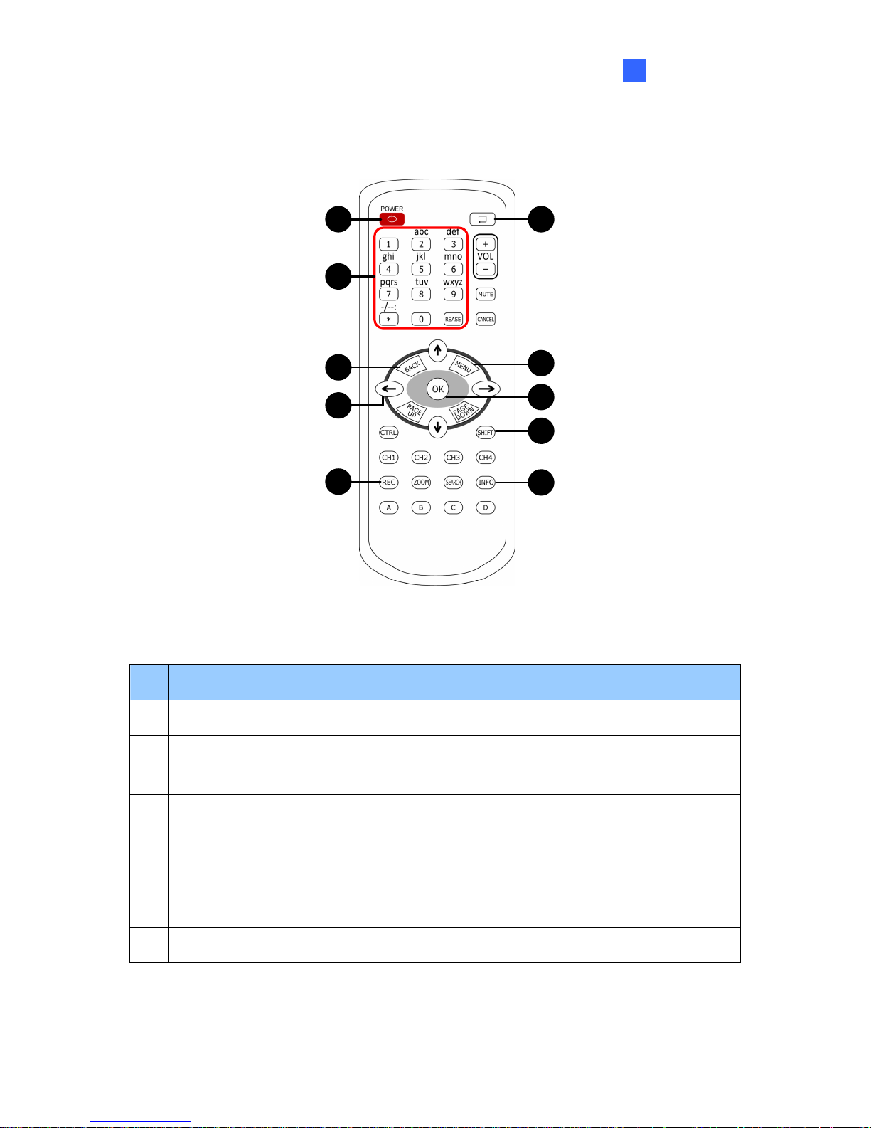
1.6 The IR Remote Control
1
2
3
4
5
6
7
8
9
10
Figure 1-4
No. Name Function
1 Power Turn on or off the GV-IP Decoder Box.
2
Numeric / Alphabetical /
Punctuation Marks keys
Enter numbers, alphabets or punctuation marks.
3 Back Back to the previous page in the Setup Menu.
4 Arrow
z Move up, down, right and left in the Setup Menu.
z Right arrow key: select a channel on the Device List.
z Left arrow key: unselect a channel on the Device List.
5 REC Capture a snapshot.
Page 14
8
No. Name Function
6 Loop Start / Stop
z Start or stop sequential display.
z Display and fix at a channel: press the Loop Start / Stop
key, a numeric key and OK to display and fix at the
selected channel. Press 0 and OK to return to the last
displayed channel.
7 Menu Switch to the setup menu.
8 OK
z Save settings in the Setup Menu.
z Display selected channels.
Switch among the 8 resolutions. When the key is pressed, the
Green LED on the front panel flashes. Press No. 0 ~ 7 for the
desired resolution within 30 seconds.
Shift + 0 : VGA_640 x 480
Shift + 1 : VGA_1024 x 768
Shift + 2 : VGA_1280 x 768
Shift + 3 : VGA_1366 x 768
Shift + 4 : High Definition_480p
Shift + 5 : High Definition_720p
Shift + 6 : High Definition_1080i
Shift + 7 : High Definition_1080p
9 Shift
Note after the resolution is configured, the green LED will fade
and GV-IP Decoder Box will reboot automatically.
10 INFO
Shows the camera name and total number of cameras under
display.
Page 15
9
Chapter 2 Getting Started
2.1 Installing the GV-IP Decoder Box
You can install the GV-IP Decoder Box on wall, behind a VESA monitor or simply use it as
desk mount device.
Wall Mount Installation
For wall mount installation, you need to purchase the wall mount kit.
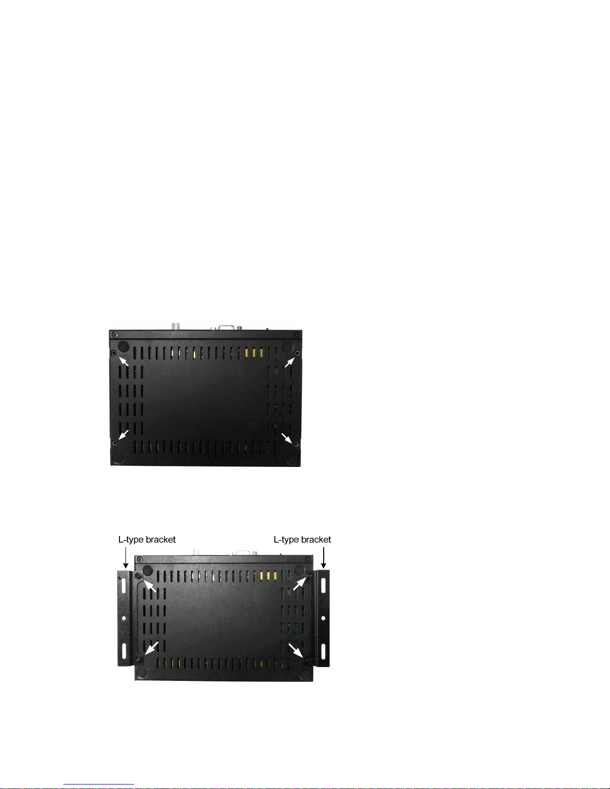
1. Unscrew the 4 screws on the back panel of the GV-IP Decoder Box.
Figure 2-1
2. Use the 4 small screws in the package to tighten the L-type brackets on the GV-IP
Decoder Box.
Figure 2-2
Page 16
10
VESA Monitor Mount
For VESA monitor mount, you need to purchase VESA Monitor mount kit.
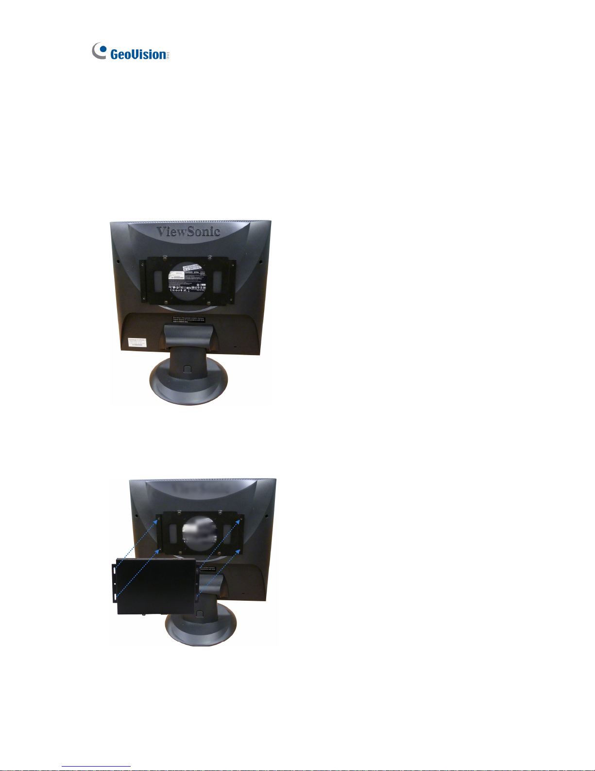
1. Follow steps 1 and 2 in Wall Mount Installation to install the L-type brackets on the back
panel of GV-IP Decoder Box.
2. Attach the VESA monitor mount bracket on the back of the computer monitor with 4 large
screws.
Figure 2-3
3. Secure the GV-IP Decoder Box with the VESA monitor mount bracket together with 4
small screws.
Figure 2-4
Page 17
Getting Started
11
2
2.2 Connecting the GV-IP Decoder Box
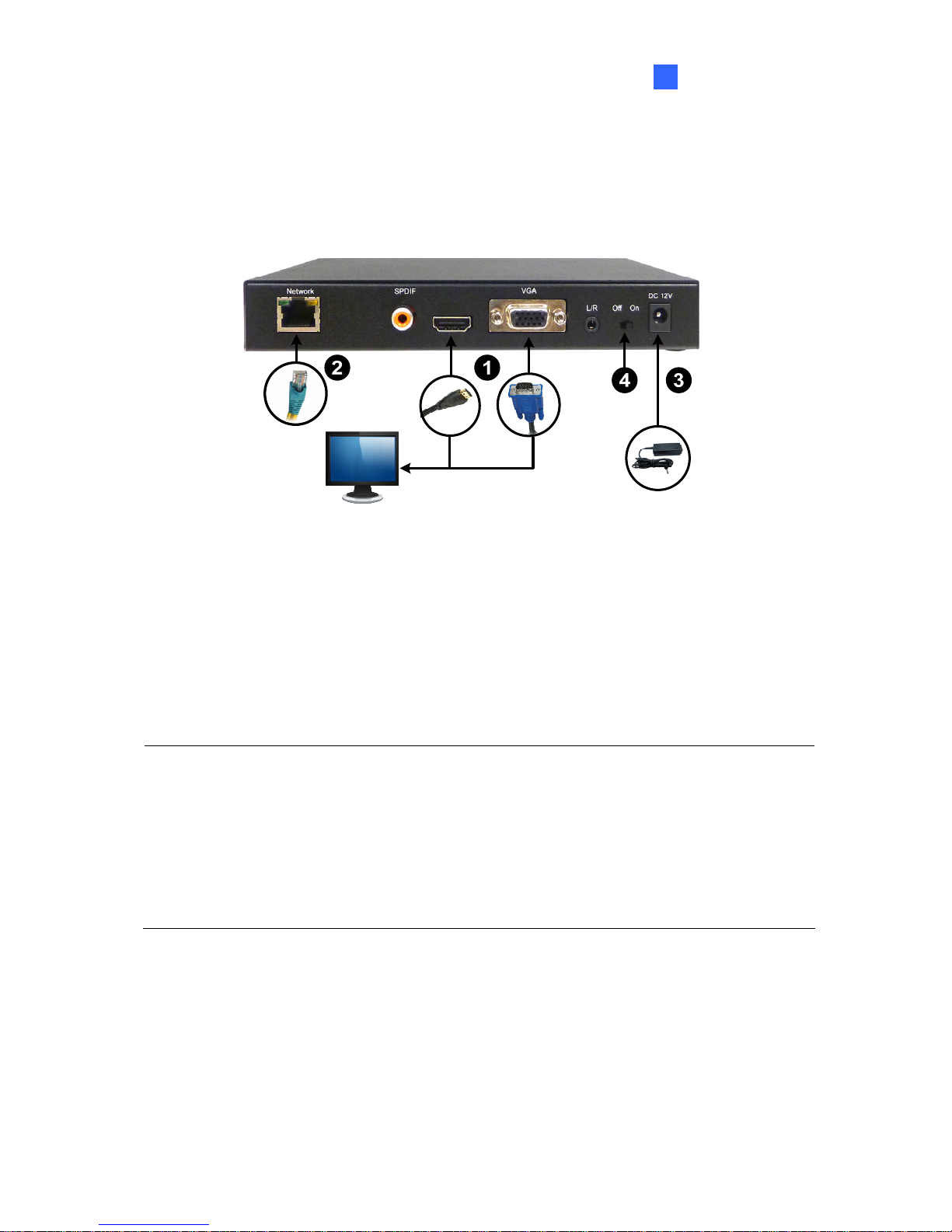
Follow the steps below to connect the GV-IP Decoder Box:
Figure 2-5
1. Connect a display device to VGA connector or High Definition connector for video output.
2. Connect to a standard network cable.
3. Connect to power using the supplied power adapter.
4. Turn the Power switch to ON.
Note:
1. You can only connect the GV-IP Decoder Box to one display device through the High
Definition or VGA connector.
2. The default video output is set to VGA with 1024 x 768 resolutions. If you use a High
Definition monitor, be sure to change the output type. To change the default setting or
configure the output type, see 3.5 Configuring the Account, Storage and Output Type.
Page 18
12
2.3 Configuring the IP Address, ID and Password
After you have installed and connected the necessary cables, you are ready to configure the
IP address, ID and password. The GV-IP Decoder Box supports two types of network
environments: fixed IP address and DHCP for dynamic IP address assignment. Depending
on your network, set up a static IP address or choose DHCP for dynamic IP address
assignment by the DHCP server.
The GV-IP Decoder Box contains two sets of ID and password: one set is required when
configuring GV-IP Decoder Box through GV-IP Device Utility; the other set is for direct
connection between GV IP devices and GV-IP Decoder Box.
Note:
1. By default, the GV-IP Decoder Box has the IP address of 192.168.0.10 and the ID and
password are admin.
2. Since all GV IP devices have the default IP address 192.168.0.10, it is advisable to
configure the IP address of your GV-IP Decoder Box to avoid IP conflict.
3. When connecting to GV-IP Decoder Box (see 2.4 Displaying Channels from GV IP
Devices), the GV IP devices need to have the same ID and password set on the GV-IP
Decoder Box.
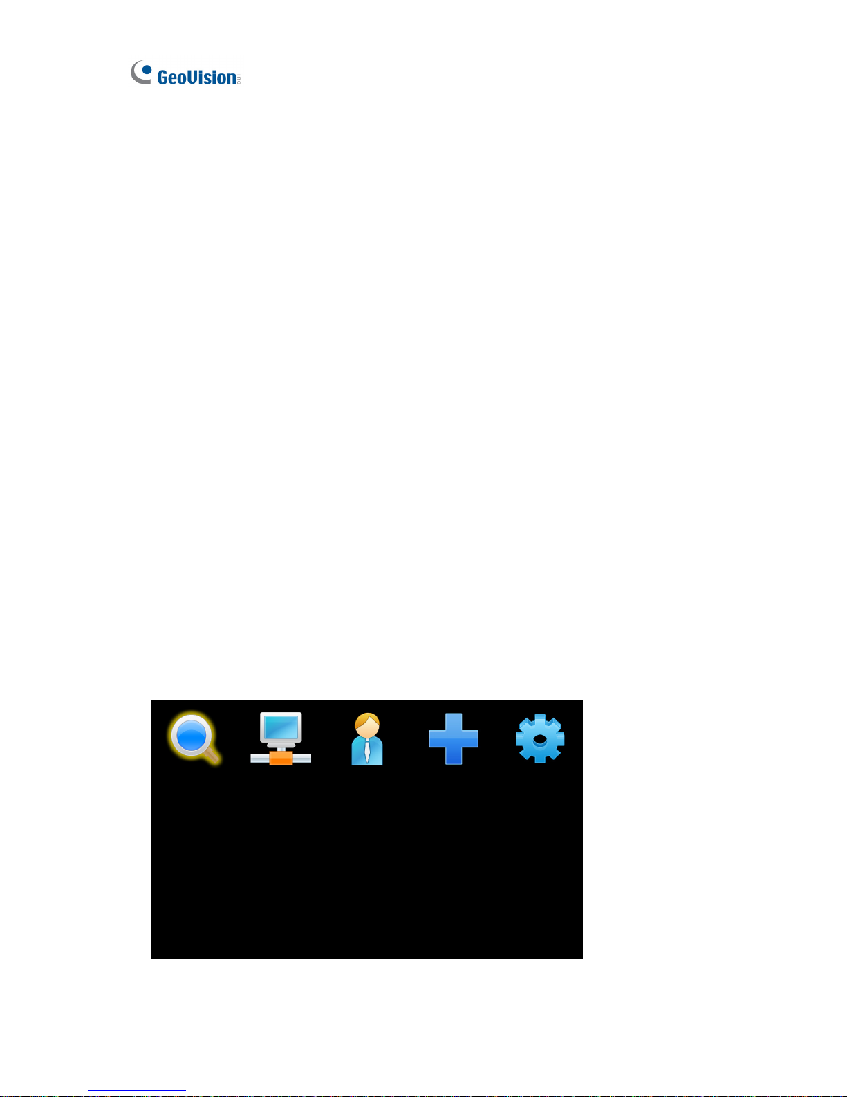
1. Power on your GV-IP Decoder Box. The main menu appears.
Figure 2-6
Page 19
Getting Started
13
2
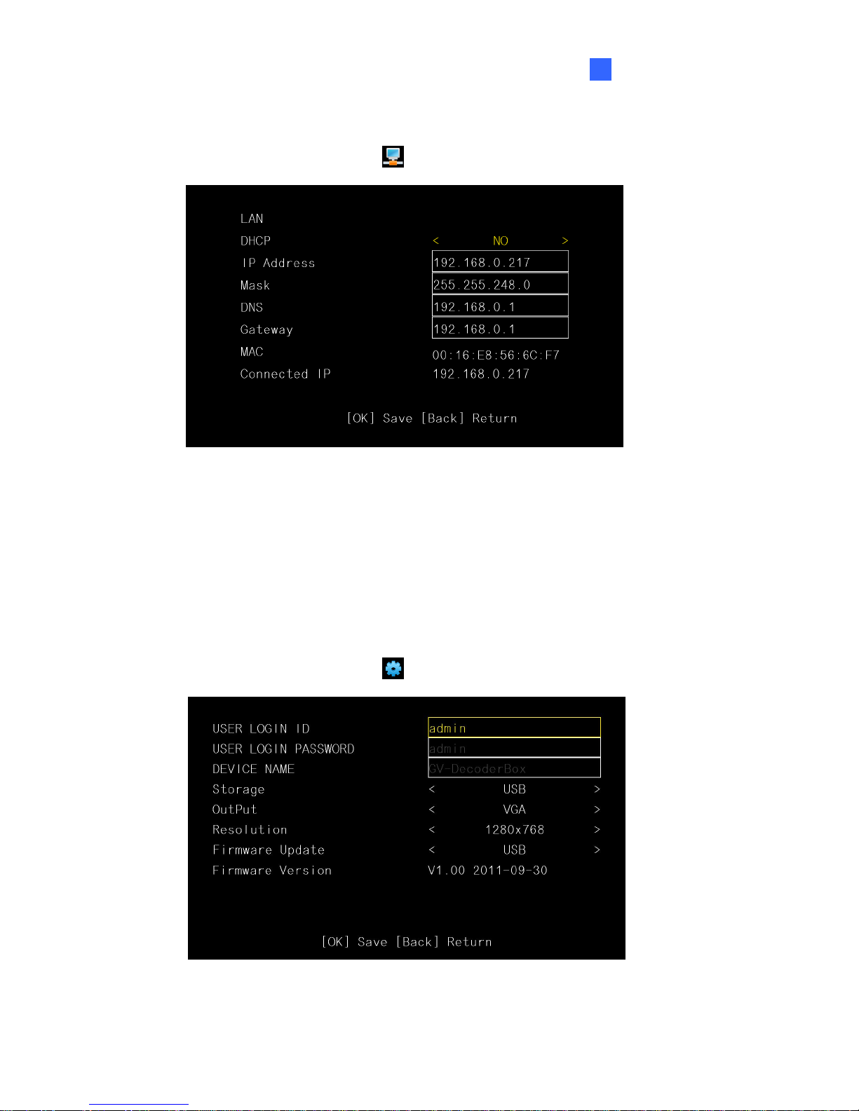
2. To configure the IP address, follow the steps below.
A. On the main menu, select the
icon and press OK. This window appears.
Figure 2-7
B. If you want to use the IP address assigned by the DHCP server under the LAN,
select Yes for the DHCP option, and press OK to confirm.
C. If you want to set up a static IP address, type the network information as required
and press OK.
D. The system will restart and the green LED will fade. Wait for the green LED to return.
3. To configure ID and password for GV-IP Decoder Box, follow the steps below.
A. On the main menu, select the
icon and press OK. This window appears.
Figure 2-8
Page 20
14
B. Type the ID and password and press OK to confirm. The maximum number of
characters is 14.
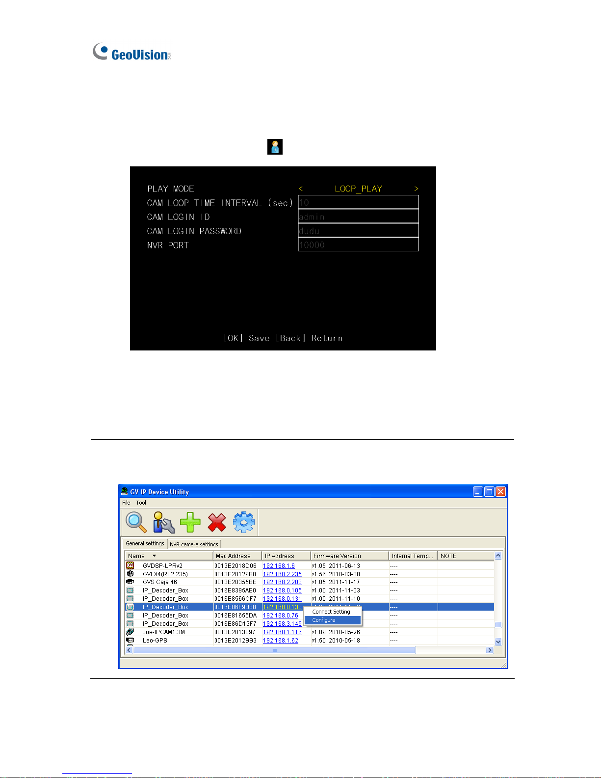
4. To configure the ID and password for GV IP device connection, follow the steps below.
A. On the main menu, select the
icon and press OK. This window appears.
Figure 2-9
B. Type the ID and password and press OK to confirm. The maximum number of
characters is 15.
Tip: You may also use GV IP Device Utility to modify the IP address by clicking the GV-IP
Decoder Box and selecting Configure.
Page 21
Getting Started
15
2
2.4 Displaying Channels from GV IP Devices
Use the search feature on GV-IP Decoder Box to display channels from GV IP devices
installed under the same LAN.
Before you start:
z This method only applies to GeoVision IP devices under the same LAN with GV-IP
Decoder Box.
z The NVR port (of GV-IP Decoder Box) and VSS port (of GV IP Devices) must be the
same.
z The ID and password set on GV IP devices and GV-IP Decoder Box (step 4 in 2.3
Configuring the IP Address, ID and Password) must be the same.
Note:
1. To add third-party IP channels, see 2.5 Displaying Channels Using GV IP Device Utility.
2. To add channels connected to GV-System, see 2.6 Displaying Channels from
GV-System.
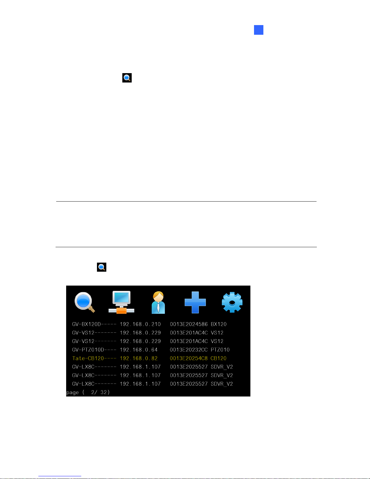
1. Select the
icon and press OK. The GV IP devices under the same LAN with the
GV-IP Decoder Box will appear on the Device List
Figure 2-10
Page 22
16
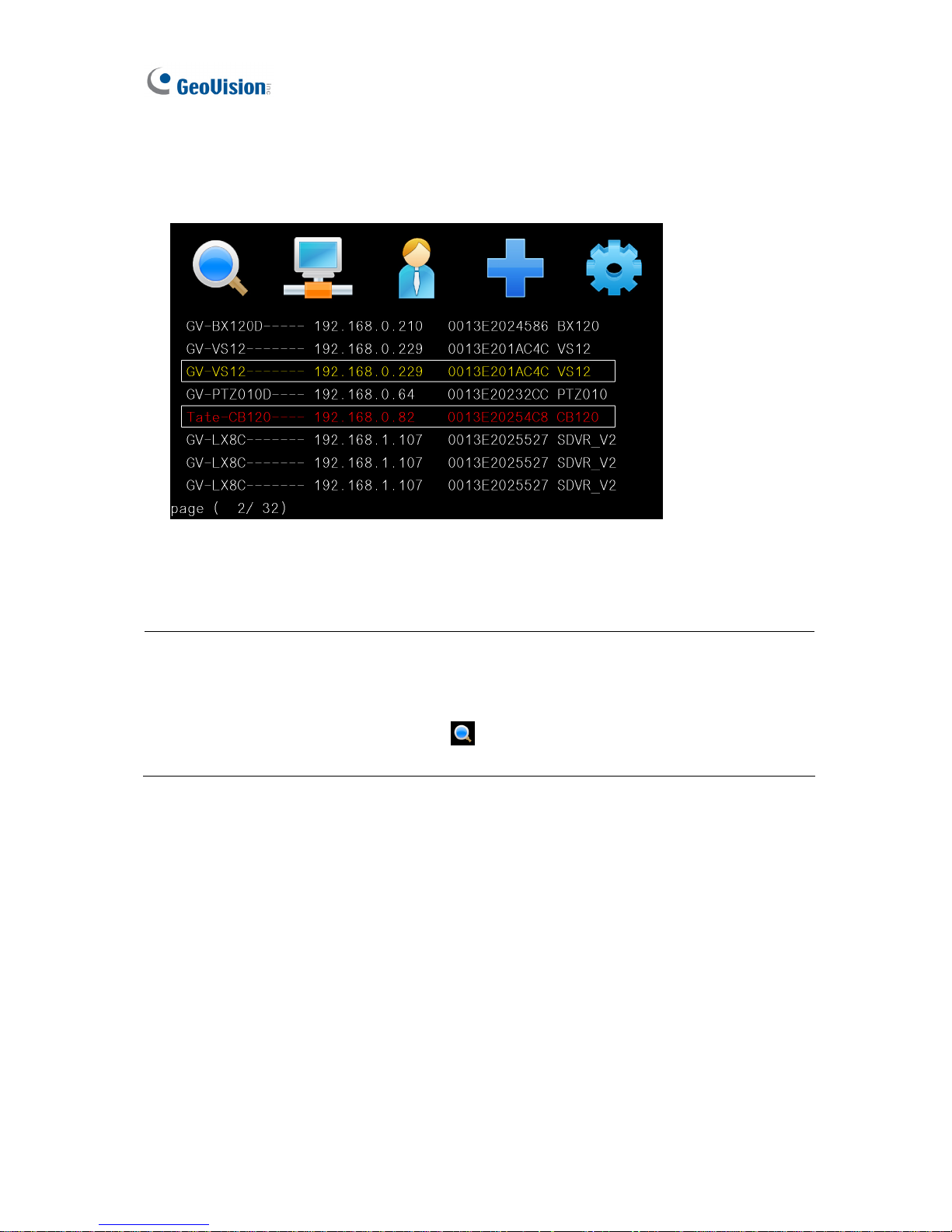
2. To select channels, press the up and down arrow keys (No.4, Figure 1-4) and press the
right arrow key. The yellow shows the cursor position and the selected channels will be in
red.
Figure 2-11
3. Press the OK key. The selected channels will be displayed.
Note:
1. When the system idles over 30 seconds or resumes after power interruption, the GV-IP
Decoder Box will automatically display channels based on the last successful settings.
2. Every time when the search function
is performed, any channels selected
previously on the Device List will be unselected.
Page 23
Getting Started
17
2
2.5 Displaying Channels Using GV IP Device Utility
You may utilize the GV IP Device Utility to add and display channels from GV IP devices,
GV-System (through GV-Mobile Server) and third-party IP devices that adhere to RTSP,
ONVIF or PSIA.
Note:
1. The GV-IP Decoder Box can decode a total of 64 channels from GeoVision and
third-party IP devices.
2. GV IP Device Utility is available on Software DVD. ONVIF and PSIA support is only
available on the GV IP Device Utility V8.53.
Figure 2-12
Page 24
18
1. Make sure your GV IP devices, GV-System or third-party IP devices are under same LAN
with the GV-IP Decoder Box.
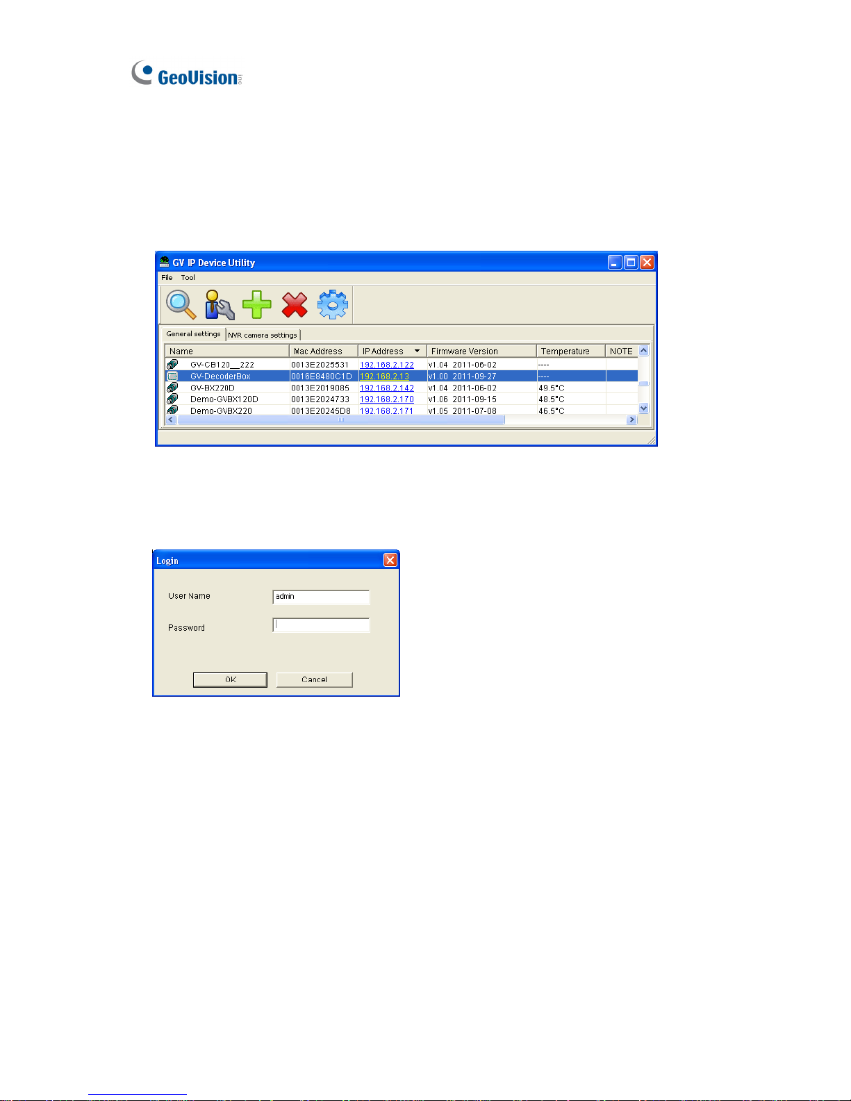
2. Make sure you have installed the GV IP Device Utility program. Double-click the GV IP
Device Utility icon on the desktop. The GV IP Device Utility window appears. It will
automatically search for all the GV IP devices under the same LAN.
Figure 2-13
3. Click on the IP address of your GV-IP Decoder Box and select Connect Setting. This
dialog box appears.
Figure 2-14
Page 25
Getting Started
19
2
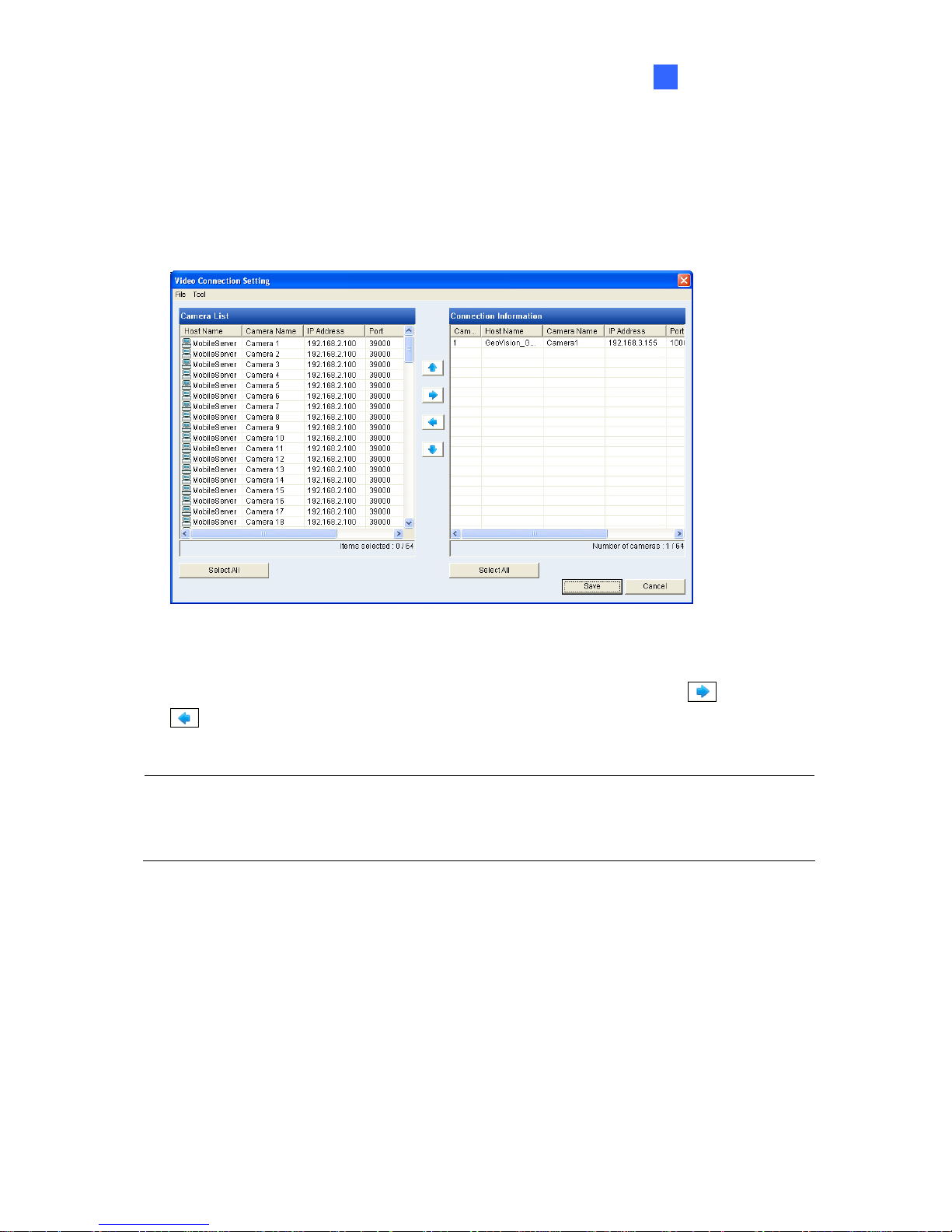
4. Type the ID and password of your GV-IP Decoder Box and click OK. For detail, see step 3
in 2.3 Configuring the IP Address, ID and Password. The Video Connection Setting
window appears. The IP devices under the same LAN with the GV-IP Decoder Box will be
listed in the Camera List column, and the connected channels will be listed in the
Connection Information column.
Figure 2-15
5. To connect to a GV IP device or devices from GV-System, use the right
and left
buttons to add or remove the device.
IMPORTANT: To select and connect to channels from GV-System, be sure you have run and
configured GV-Mobile Server. For setup steps, see 2.6 Displaying Channels from
GV-System.
6. Right-click the added channel, select Edit and type the username and password of the
channel to log in. By default, the login ID and password for all GV IP devices are admin.
Page 26
20
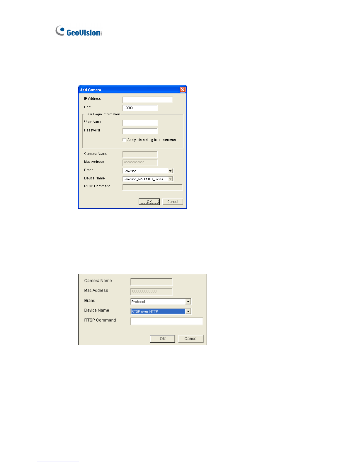
7. To add a third-party IP camera, follow the steps below.
A. Click Tool on the Video Connection Setting window, and select Add Camera. This
dialog box appears.
Figure 2-16
B. Type the IP address, user name and password of the device.
C. Select Protocol for Brand and one of the following protocol for Device Name. Type
the RTSP command if required. Refer to your third-party IP camera’s manual for this
information.
Figure 2-17
ONFIV: Select this protocol if your camera adheres to ONVIF.
PSIA: Select this protocol if your camera adheres to PSIA.
RTSP over HTTP: The RTSP protocol uses an HTTP port for data streaming
from the IP camera.
Page 27
Getting Started
21
2
RTSP over TCP: The RTSP protocol uses a TCP port for data streaming from
the IP camera.
RTSP over UDP: The RTSP protocol uses a UDP port for data streaming from
the IP camera.
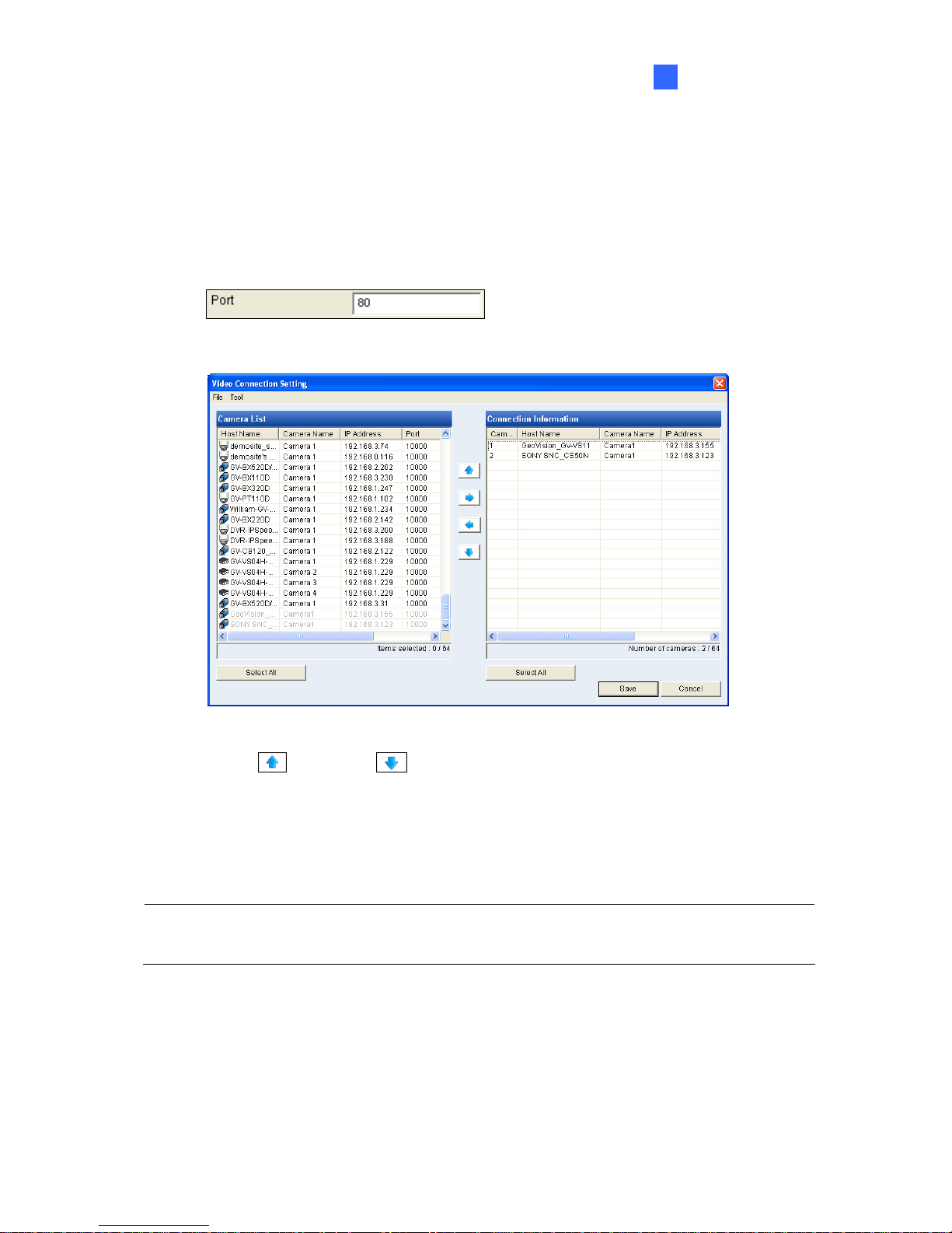
D. For ONVIF and PSIA, modify the Port to 80, else keep the port in default.
E. Click OK. The camera will be added to the list.
Figure 2-18
8. Use the up
and down
buttons to move the added channels up and down the
Connection Information list. The channels will be displayed according to this order.
9. Click Save. The cameras on the Connection Information column will be updated to the
GV-IP Decoder Box and displayed on the monitor.
Note: When the system idles over 30 seconds or resumes after power interruption, the
GV-IP Decoder Box will automatically display channels based on the last successful settings.
Page 28
22
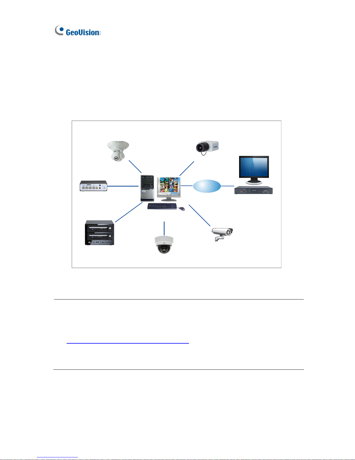
2.6 Displaying Channels from GV-System
You can access the analog and IP channels connected to GV-System through GV-Mobile
Server. Through GV-Mobile Server, the GV-IP Decoder Box can decode and display:
z up to 32 H.264 and non-H.264 channels that are connected to GV-System.
z up to 4 channels of matrix view.
GV-IP Camera
GV-PT/PTZ
GV-IP Speed Dome
GV-Video Server
GV-Compact DVR
Some 3rdparty IP cameras
Analog camera
LAN
GV-IP Decoder Box
Computer installed with
GV-System & GV-Mobile Server
Figure 2-19
Note:
1. The GV-Mobile Server program can be found in the software DVD of GV-System.
2. For the compatible third-party IP devices with GV-System, visit
http://www.geovision.com.tw/english/4_21.asp
3. The GV-IP Decoder Box can decode a total of 64 channels from GeoVision and
third-party IP devices.
Page 29
Getting Started
23
2
1. Set up the desired IP channels on GV-System. For setup steps, see Chapter 2 Hybrid and
NVR Solution in the Multicam Digital Surveillance System User’s Manual in GV-System’s
accompanying software DVD.
2. Go to Windows Start, point to Programs, select GV-Mobile Server and run Mobile
Server. The GV-Mobile Server window appears.
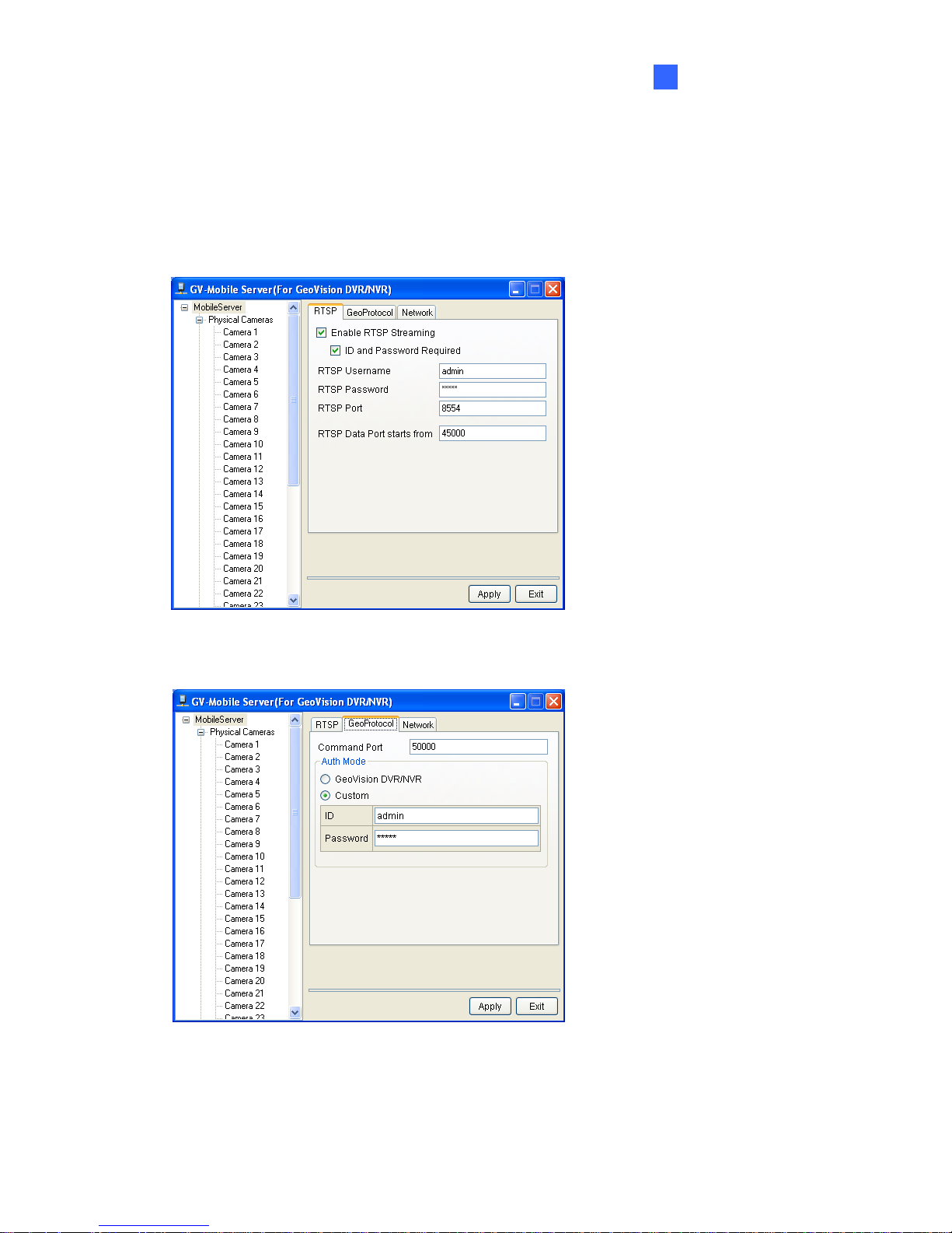
Figure 2-20
3. Click the GeoProtocol tab. This window appears.
Figure 2-21
Page 30
24
4. To connect directly with GV-IP Decoder Box, change the port to 10000.
Note: If you are using GV-Mobile Server firmware before V1.2 and connect through GV IP
Device Utility, modify the command port to 39000.
5. Select Custom and type the ID and password of the GV-Mobile Server. To connect
directly with GV-IP Decoder Box, the ID and password must match the CAM Login ID and
password set on the GV-IP Decoder Box (Figure 2-9).
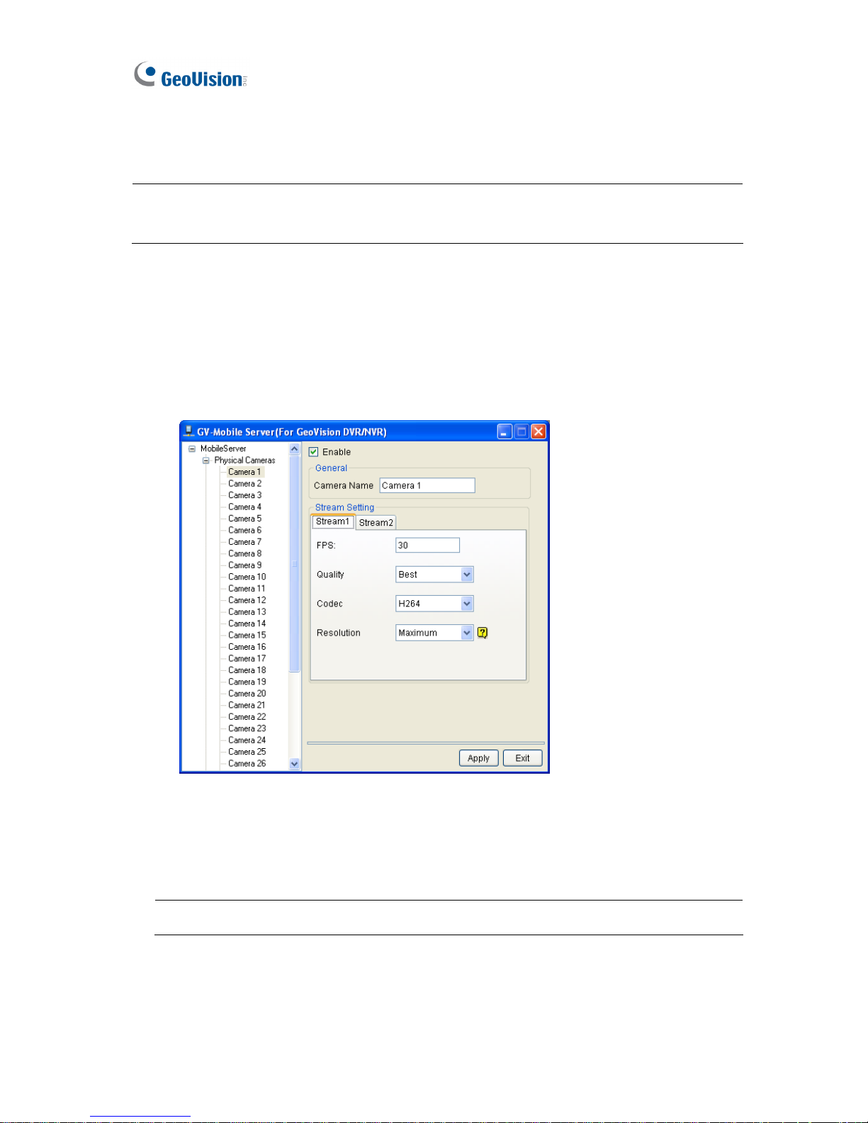
6. Configure each connected channel.
A. Click a camera number on the device tree. This window appears.
Figure 2-22
B. Type the frame rate in the FPS field and select a Quality and Resolution using the
drop-down lists. The maximum resolution supported for streaming is 704 x 480.
C. Select H.264 for Codec.
Note: The GV-IP Decoder Box supports Stream 1 and H.264 codec only.
D. Repeat steps A to C to configure another channel.
Page 31
Getting Started
25
2
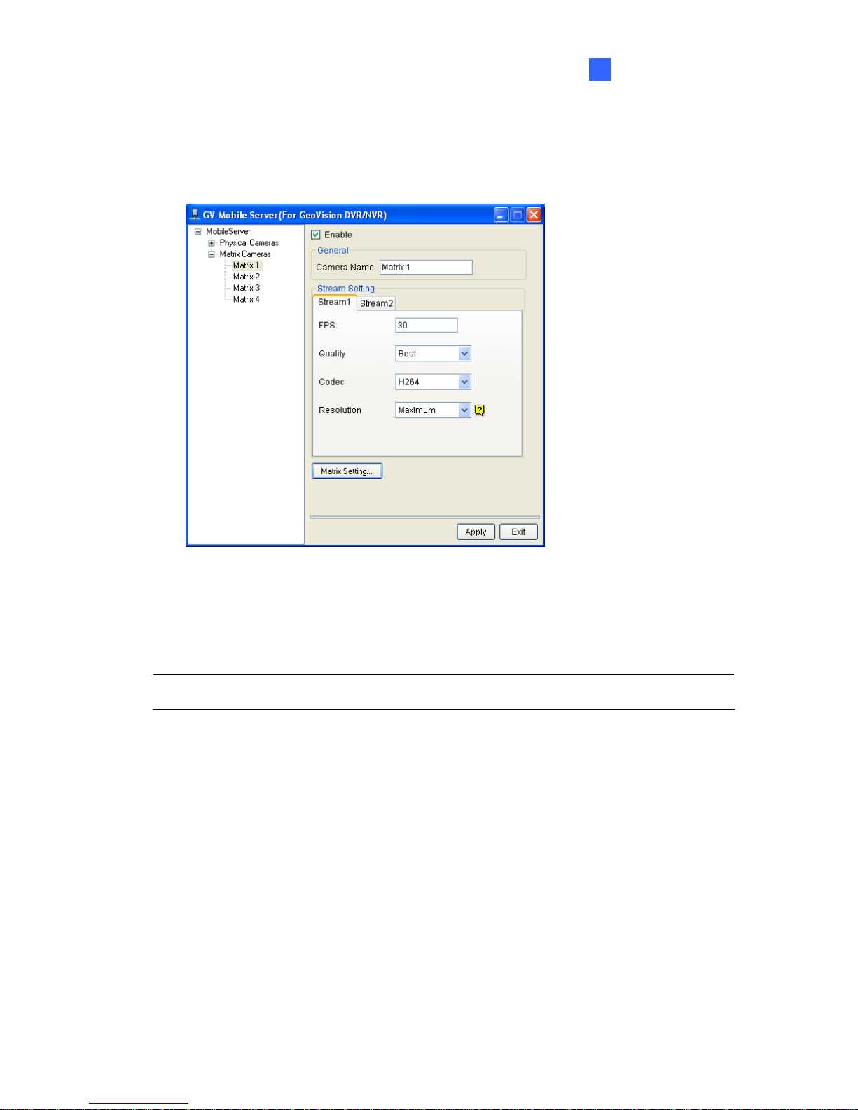
7. To establish matrix view, follow the steps below.
A. On the GV-Mobile Server window, select a Matrix number from the device tree. This
window appears.
Figure 2-23
B. Type the frame rate in the FPS field and select a Quality and Resolution using the
drop-down lists. The maximum resolution supported for streaming is 1.3 M.
C. Select H.264 for Codec.
Note: The GV-IP Decoder Box supports Stream 1 and H.264 codec only.
Page 32
26
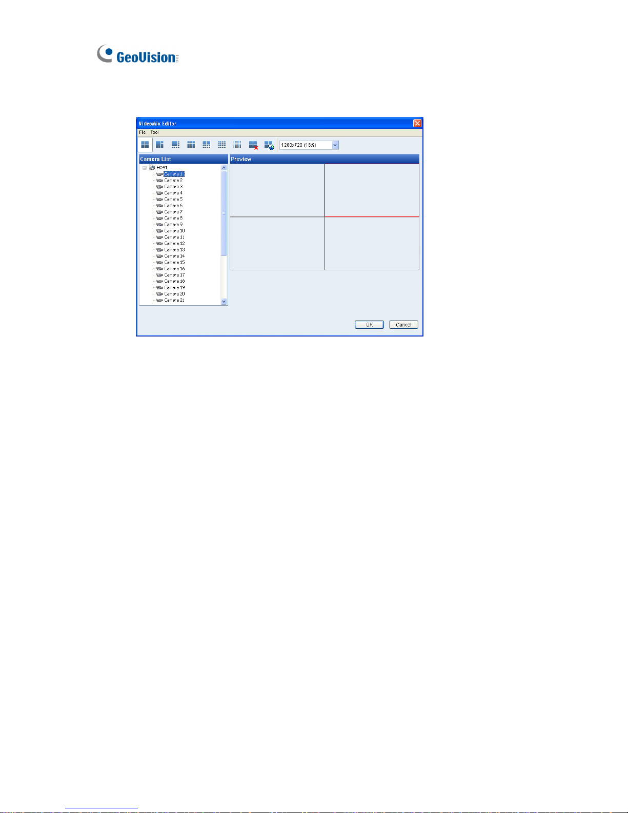
D. Click the Matrix Setting button. The window appears.
Figure 2-24
E. Select a matrix pattern from the top.
F. Click and drag channels from the device tree.
G. Click OK.
8. Click Apply.
9. To preview, right click the channel in the left menu, and select one of the following:
View Actual Stream: Watch the channel view received by the GV-Mobile Server.
View Encode Stream 1: Watch the channel view set up in step 6 (for single channel)
or step 7 (for matrix view).
View Encode Stream 2: Stream 2 will not be received by the GV-IP Decoder Box.
Page 33
Getting Started
27
2
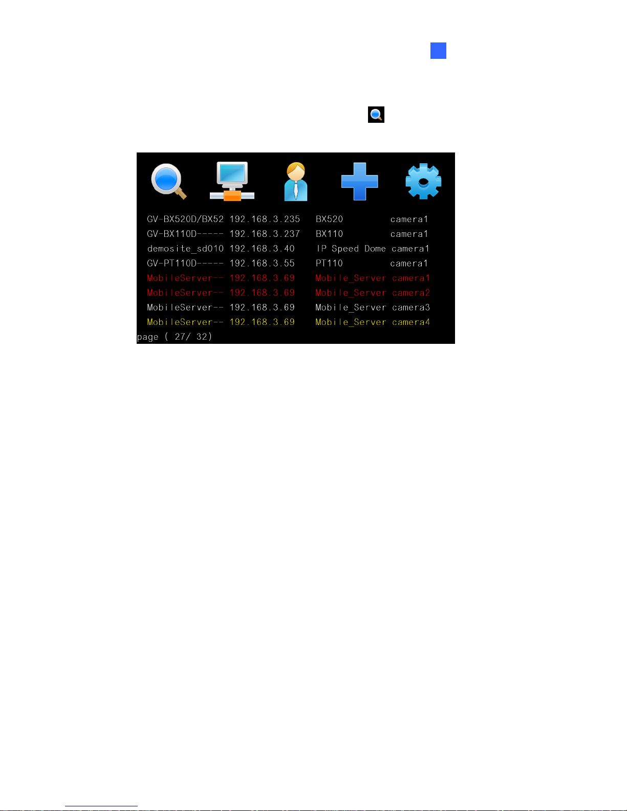
10. To connect directly from GV-IP Decoder Box, follow the steps below.
A. On the main menu of GV-IP Decoder Box, select
and press OK to search. The
channels of GV-Mobile Server will be listed.
Figure 2-25
B. To select channels, press the up and down arrow keys (No.4, Figure 1-4) and press
the right arrow key. The yellow shows the cursor position and the selected channels
will be in red.
C. Press the OK key. The selected channels will be displayed.
11. To connect using GV IP Device Utility, follow steps in 2.5 Displaying Channels Using GV
IP Device Utility.
Page 34
28
2.7 Taking a Snapshot
The security administrators can capture images when events occur. Snapshot images are
automatically saved to an inserted storage device such as a USB drive or SD card in JPEG
format.
Before you start, be sure:
z you have inserted a USB drive or SD card for storage.
z you have at least 30 MB of space on your storage device.
z the storage type is correctly configured.
Otherwise, the error icon
will appear when attempting to capture an image.
1. On the main menu, select
and select the inserted storage device under Storage.
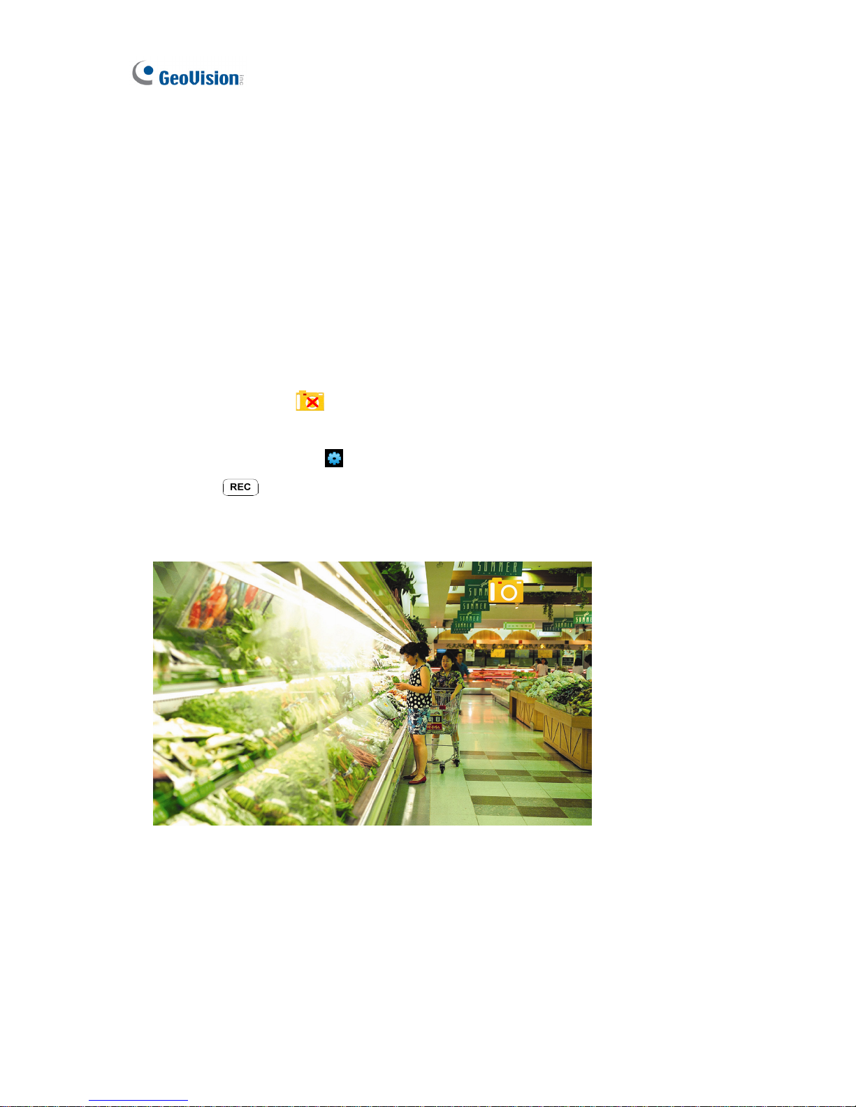
2. Press the
key to capture the image. A camera icon appears at the top right corner
of the monitor and 3 consecutive snapshots will be taken and saved to the inserted
storage device.
Figure 2-26
Page 35
Getting Started
29
2
2.8 Pausing the Looped View
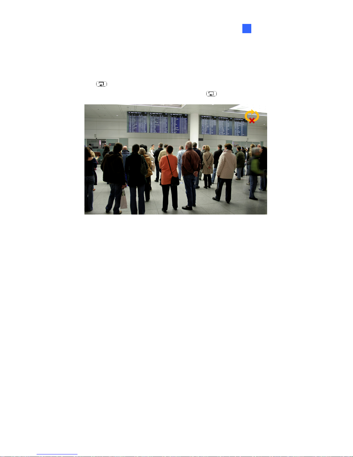
You can pause the looped view and fix the display on a single channel. To pause the looped
view, press the
key. A loop sign with a cross will appear on the top-right corner of the
display channel. To resume to the looped view, press the
key again.
Figure 2-27
Page 36
30
2.9 Controlling PTZ Cameras
The GV-Joystick can be connected to the GV-IP Decoder Box to control GV-PTZ010D,
GV-PT110D and GV-IP Speed Dome. The supported functions include zoom in, zoom out, tilt
(vertical movement), pan (horizontal movement), focus in, focus out and automatic focus.
Note:
1. GV-Joystick cannot control channels accessed through GV-Mobile Server or RTSP.
2. The Previous and Next buttons of GV-Joystick are not supported on GV-IP Decoder
Box.
3. The Focus In / Out buttons are not supported on GV-PT110D.
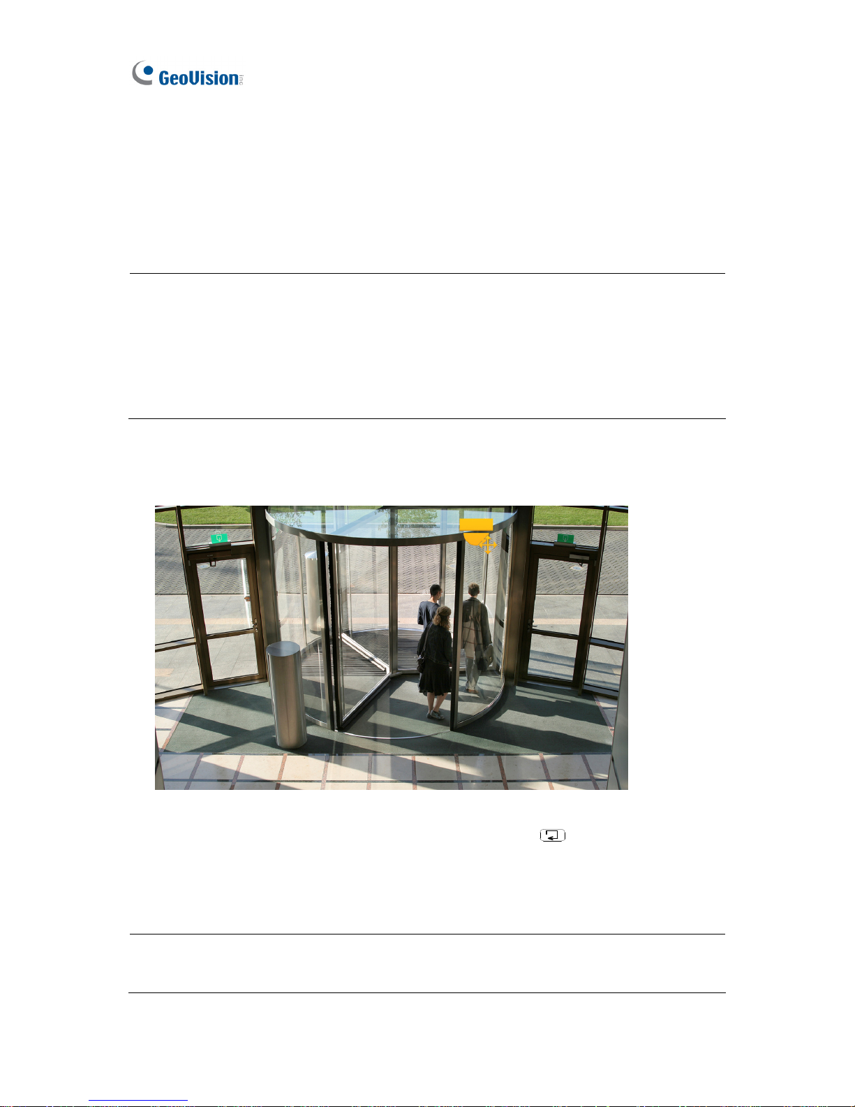
1. Connect a GV-Joystick to the USB port on the front panel. Once the GV-Joystick is
connected, the PTZ icon will appear on the channels that support the device.
Figure 2-28
2. If you have more than one channel under display, press the
key to lock the display
channel at the PTZ camera. See 2.8 Pausing the Looped View.
3. You can now start to control the camera using the GV-Joystick.
Tip: To automatically focus the channel view, press the Focus In and Focus Out buttons
on the GV-Joystick at the same time.
Page 37
31
Chapter 3 System Setup
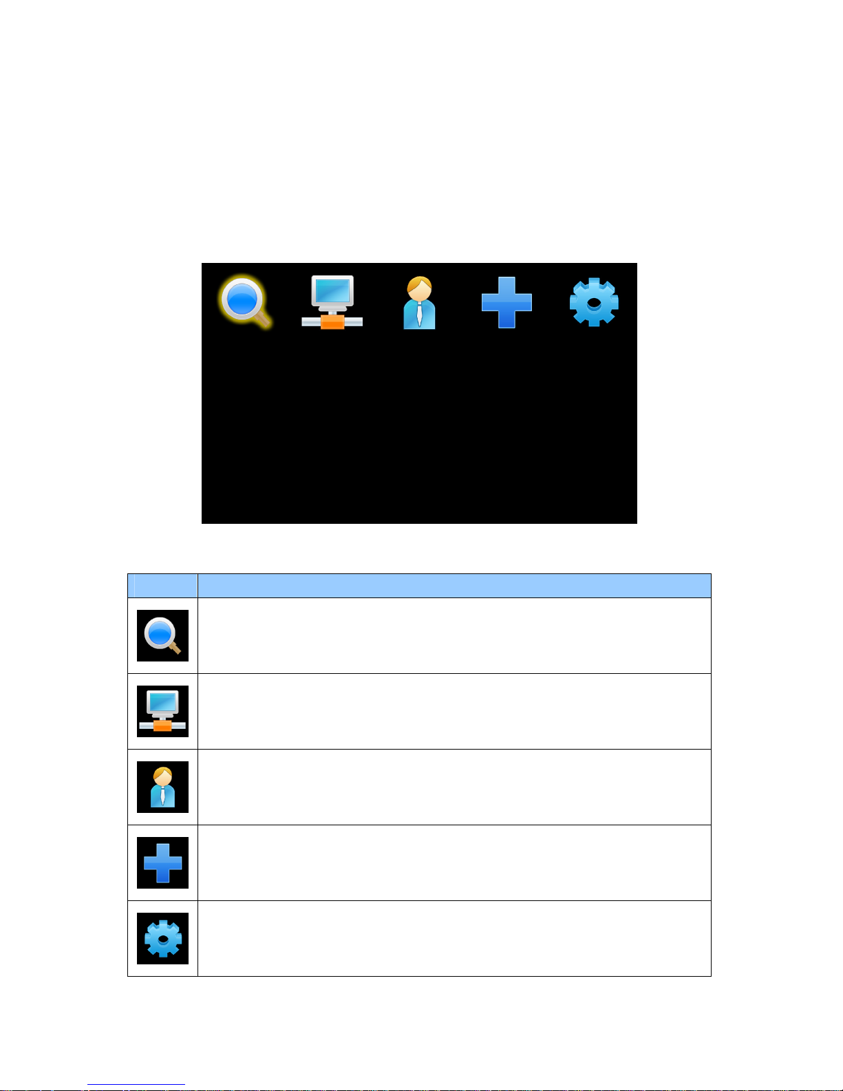
When the GV-IP Decoder Box is connected and powered on, the main menu appears on your
display monitor:
Figure 3-1
Icon Main Functions
Search for GV IP devices and GV-Mobile Server under the same LAN with the
GV-IP Decoder Box and generates a Device List. For detail, see 3.1 Searching
IP Devices.
Contains network settings of the GV-IP Decoder Box. For detail, see 3.2 Setting
the Network.
Contains the settings for IP devices to be displayed on GV-IP Decoder Box. For
detail, see 3.3 Configuring the Play Mode.
Adds a GV IP device to the GV-IP Decoder Box Device List and contains
sorting options for the Device List. For detail, see 3.4 Adding a GV IP Device.
Contains settings for account, storage, monitor type, resolution, and firmware
upgrade. For detail, see 3.5 Configuring the Account, Storage and Output Type.
Page 38
32
3.1 Searching IP Devices
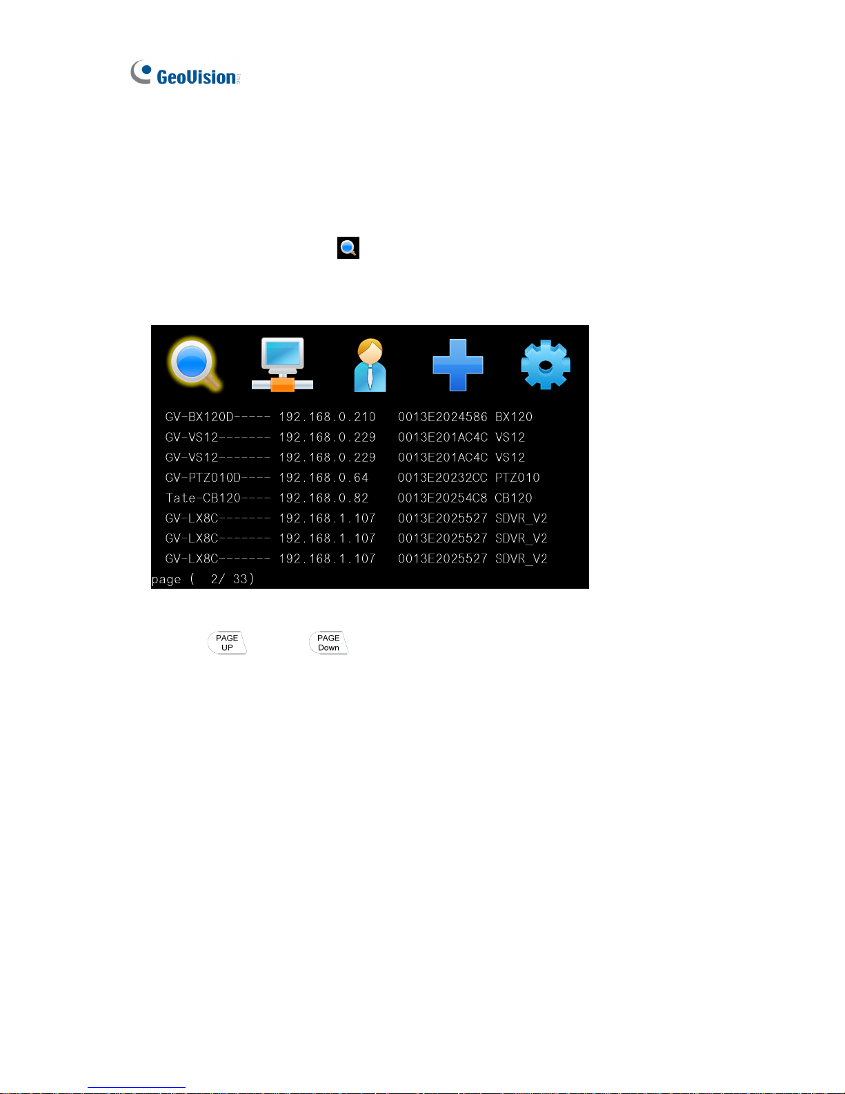
You can search the GV IP devices and Mobile Server under the same LAN with the GV-IP
Decoder Box.
1. Use the arrow keys to select
and press OK. The message “Waiting to Scan”
appears.
2. Wait for a few seconds and the Device List appears.
Figure 3-2
3. Use the
and the keys to view the list.
Page 39
System Setup
33
3
3.2 Setting the Network
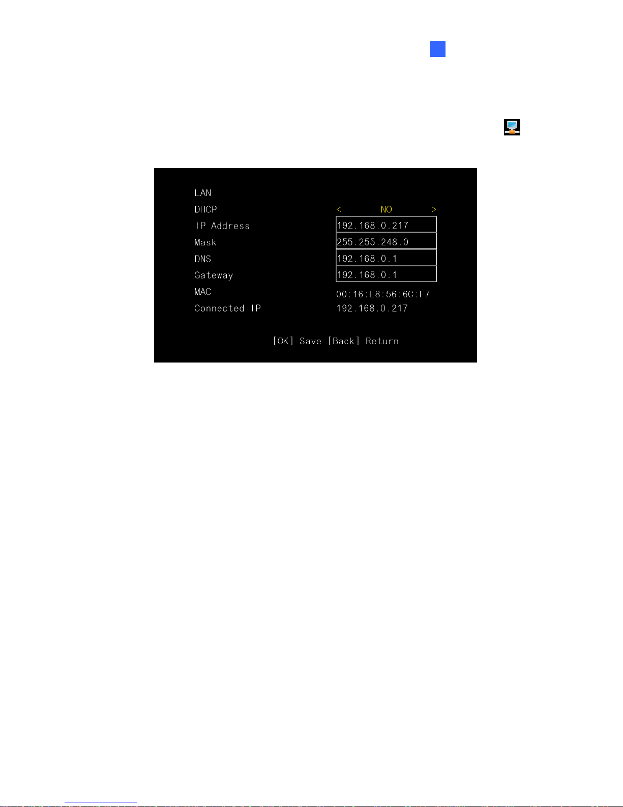
To configure the network settings for the GV-IP Decoder Box, on the main menu, select
and press OK. This window appears.
Figure 3-3
DHCP: Select Yes to enable the DHCP function; No to disable the function.
IP Address: Enter the IP address of the GV-IP Decoder Box.
Mask: Enter the mask address of the GV-IP Decoder Box.
DNS: Enter the DNS address of the GV-IP Decoder Box.
Gateway: Enter the gateway address of the GV-IP Decoder Box.
MAC: Shows the MAC address of the GV-IP Decoder Box.
Connected IP: Shows the current IP address at use.
Page 40
34
3.3 Configuring the Play Mode
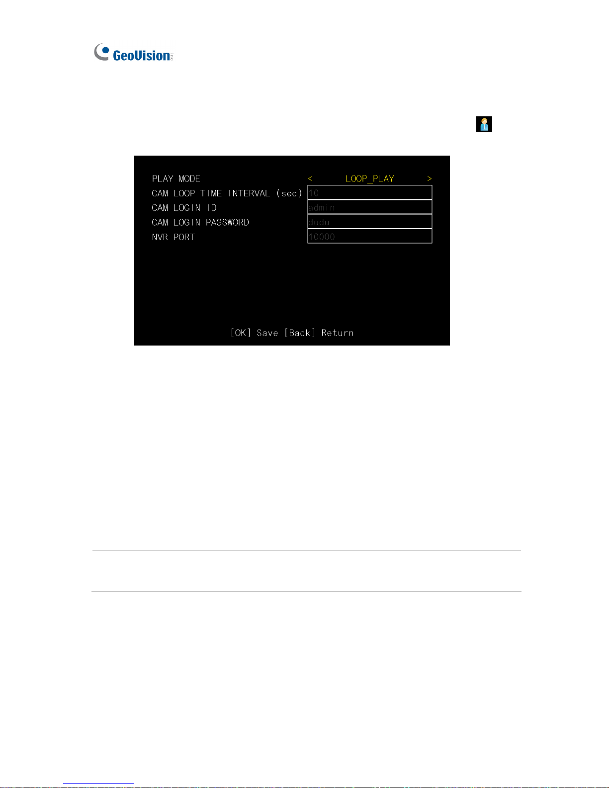
You can configure the play mode for the live view display. On the main menu, select and
press OK. This window appears.
Figure 3-4
CAM Loop Time Interval: Enter the time interval (in seconds) between each looped
channel. The valid range is from 10 to 600. The default is 30 seconds.
CAM Login ID: Enter the ID of the camera. The default is admin. The maximum
number of characters is 15.
CAM Login Password: Enter the password of the camera. The default is admin. The
maximum number of characters is 15.
NVR Port: Keep the NVR port in default (10000). Modify it only when necessary.
Note: The channels added directly with GV-IP Decoder Box for display must also have the
same ID and password established here.
Page 41
System Setup
35
3
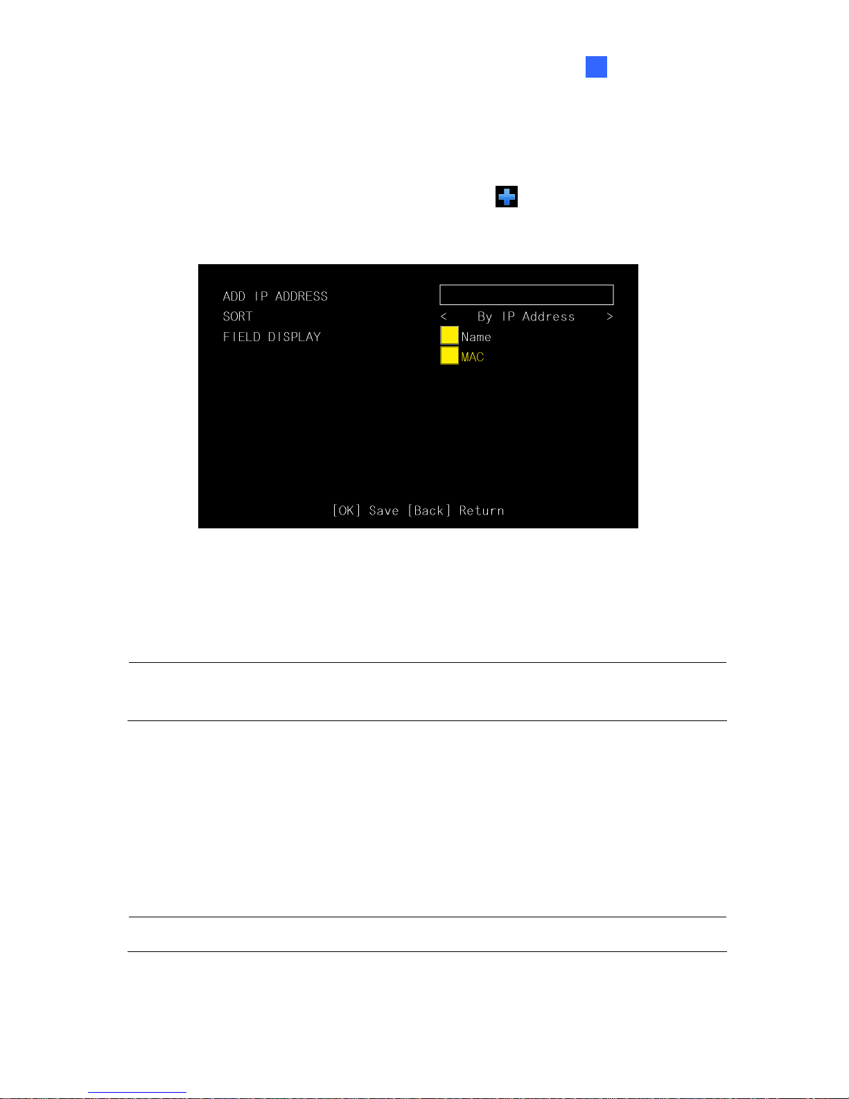
3.4 Adding a GV IP Device
You can manually add a GV IP device, select the sorting method and configure the displayed
information on the Device List. On the main menu, select
and press OK. This window
appears.
Figure 3-5
Add IP Address: Type the IP address of the GV IP device.
Note: This function is not applicable to adding third-party IP devices. To add third-party IP
cameras, see 2.5 Displaying Channels Using GV IP Device Utility.
Sort: Sort the Device List (Figure 3-2) according to IP address, MAC address, camera
name or NONE. (When NONE is selected, the IP devices will be listed in the order of
search). The default is By IP Address.
Field Display: Select or unselect the device name and/or MAC address displayed on
the Device List. The yellow block represents a selected option.
Tip: Select the Name option only to display the device name and the channel number.
Page 42
36
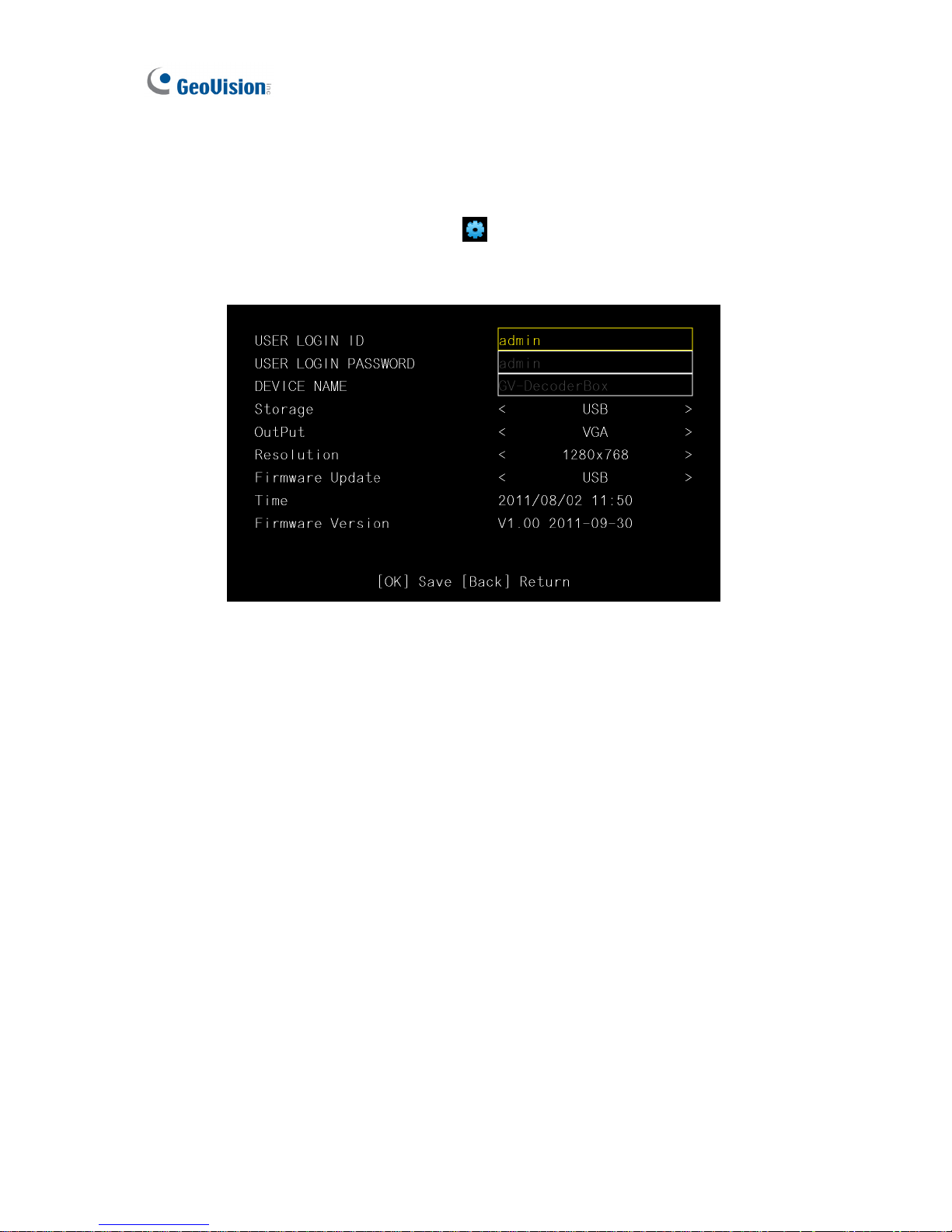
3.5 Configuring the Account, Storage and Output Type
You can configure the account information, select storage and monitor connector, and look up
firmware version. On the main menu, select
of the GV-IP Decoder Box and press OK.
This window appears.
Figure 3-6
User Login ID: Type the login ID for the GV-IP Decoder Box. The default is admin. The
maximum number of characters is 14.
User Login Password: Type the password for the GV-IP Decoder Box. The default is
admin. The maximum number of characters is 14.
Device Name: Name your GV-IP Decoder Box.
Storage: Select the inserted storage device (USB or SD).
Output: Select the output format between VGA and High Definition. The available
options for resolution will be automatically brought up.
Resolution: Select a resolution. The system will reboot when the resolution is modified.
Firmware Update: Select the device that stores the firmware files. For upgrading steps.
See 3.6 Upgrading the Firmware.
Firmware Version: Displays the firmware version of the device.
Page 43
System Setup
37
3
3.6 Upgrading the Firmware
We will periodically release the updated firmware on the website. You may choose to update
firmware locally using a USB drive or SD card, or remotely through the GV IP Device Utility
program.
Before you start:
z Be sure you have inserted a storage device (USB drive or SD card) and it contains one
firmware file only.
z The USB drive or SD card must have at least 100 MB of free space.
3.6.1 Updating Firmware through USB Drive or SD Card
1. Copy the firmware file to the root folder of a USB storage device or a SD card.
2. Connect the USB drive or SD card to the GV-IP Decoder Box.
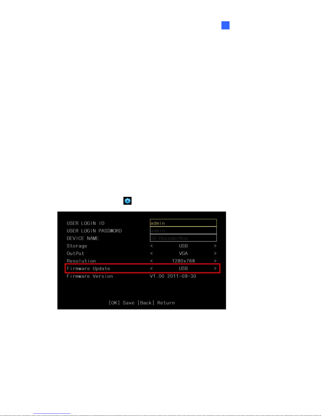
3. On the setup menu, select
and press OK. This window appears.
Figure 3-7
4. In the Firmware Update field, select USB or SD storage that stores the firmware file.
5. Press OK. The firmware upgrade runs automatically, and the GV-IP Decoder Box will
restart after the firmware upgrade is completed.
Page 44
38
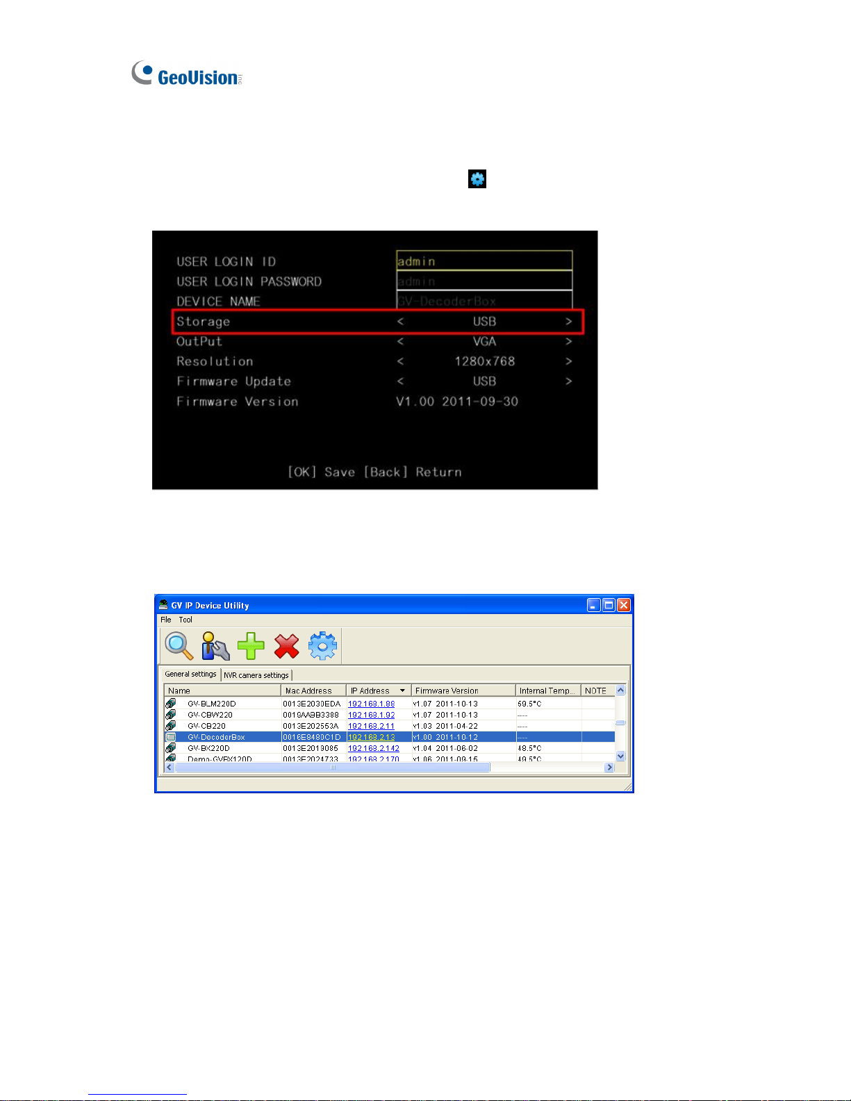
3.6.2 Updating Firmware through GV IP Device Utility
1. On the main menu of GV-IP Decoder Box, select and select the inserted storage
device under Storage.
Figure 3-8
2. Make sure you have installed the GV IP Device Utility program. Double-click the GV IP
Device Utility icon on the desktop. This window appears.
Figure 3-9
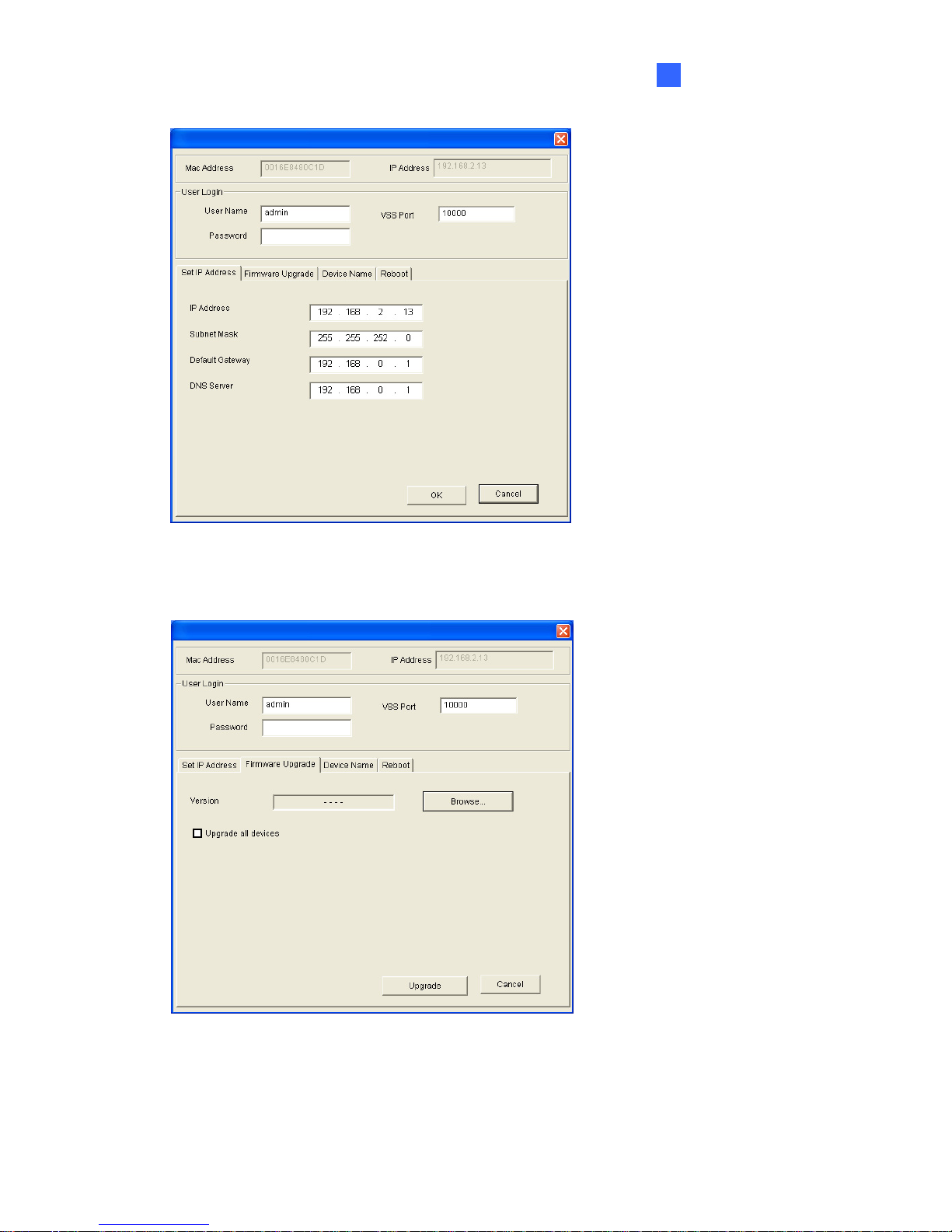
3. Click on the IP address of your GV-IP Decoder Box and select Configure. This window
appears.
Page 45
System Setup
39
3
Figure 3-10
4. Select the Firmware Upgrade tab, type the User Name and Password, and click the
Browse button to locate the firmware file saved at your local computer.
Figure 3-11
5. Type the password and click Upgrade to start upgrading. The system will reboot itself
when the upgrade is completed.
Page 46
40
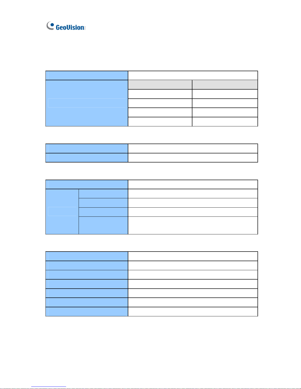
Specifications
Video
Video Codec H.264
High Definition VGA
480p 640 x 480
720p 1024 x 768
1080i 1280 x 768
Video Output at 60 Hz
1080p 1366 x 768
Network
Interface 10/100 Ethernet
Protocol TCP, RTSP, ONVIF, PSIA
Mechanical
IR Remote Control Yes
Power 12V DC Jack
Ethernet RJ-45
Monitor Output High Definition, VGA
Connectors
Local Storage &
Firmware Upgrade
USB slot (2.0 backward compatible, FAT32 format)
SD card slot (for Class 6 card or above, FAT32 format)
General
Operating Temperature 0°C ~ 40°C / 32 °F ~ 104 °F
Operating Humidity 20 % ~ 80 % (with no condensation)
Dimensions (W x H x D) 182.5 × 29 × 141.5 mm / 7.19 × 1.14 × 5.58 in
Net Weight 615 g / 1.36 lb
Power DC 12 V
Power Consumption 36 W (max. 3 A at 12V DC)
Regulatory CE, FCC compliant
All specifications are subject to change without notice.
Page 47
Introduction
41
4
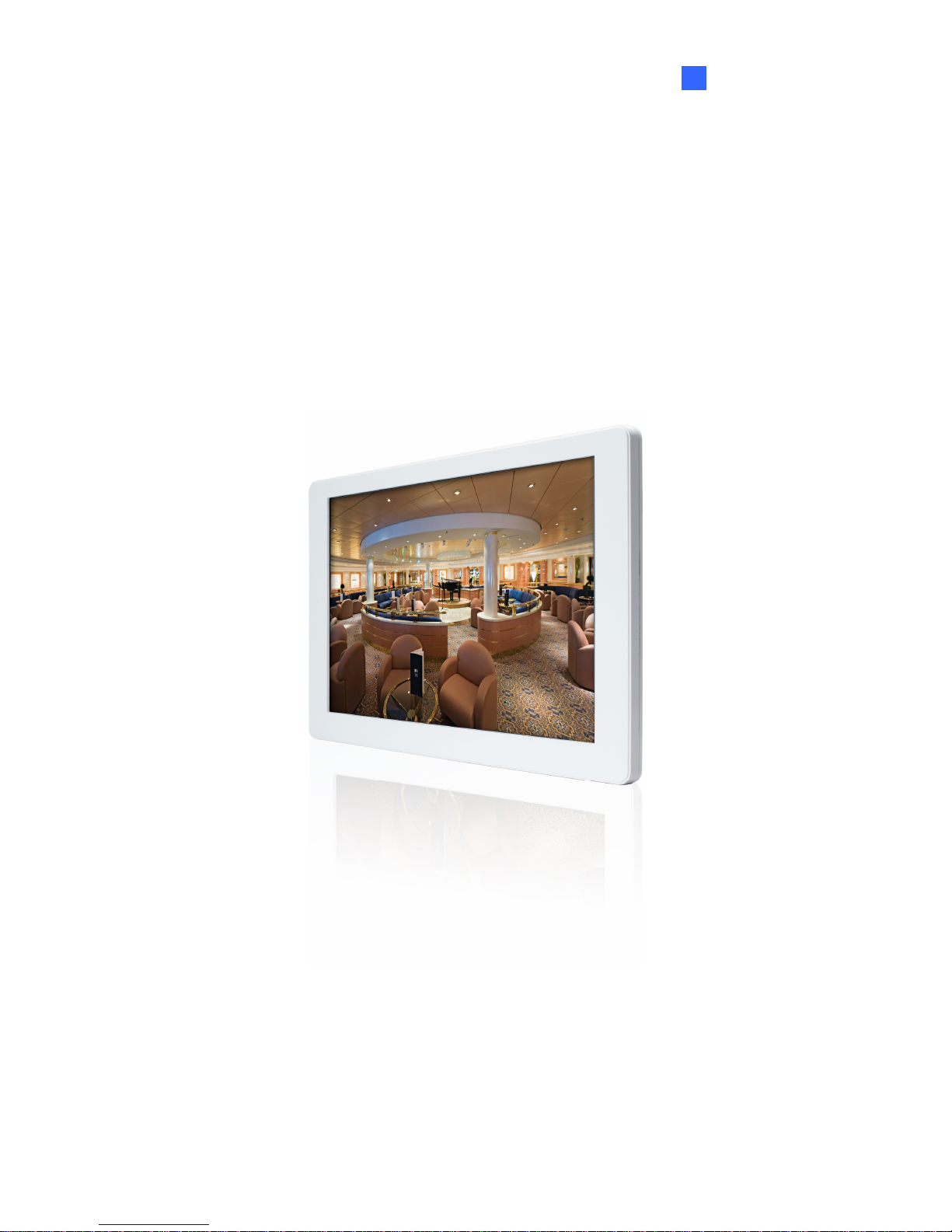
GV-Pad
Page 48
42
Chapter 4 Introduction
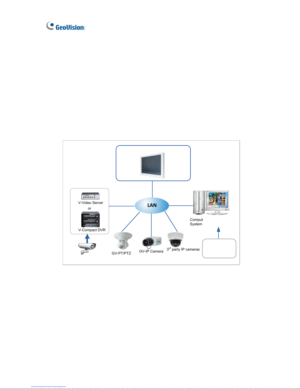
The GV-Pad is a pad that decodes and displays incoming IP streams from GeoVision and
third-party IP devices. It is light-weighted and requires only minimal amount of installation. As
a standalone device, the GV-Pad does not require an extra monitor and yet it supports almost
all the features of a GV-IP Decoder Box. Through the network, a GV-Pad can receive and
manage up to 64 IP streams simultaneously. The administrators can monitor channels, take
snapshots, pause at a specific channel and control GeoVision PTZ cameras such as
GV-PTZ010D, GV-PT110D and GV-IP Speed Dome through a connected GV-Joystick.
LAN
GV-Pad
Computer installed with GVSystem & GV-Mobile Server
GV-PT/PTZ
GV-IP Speed Dome
GV-IP Camera
3rdparty IP cameras
that support RTSP,
ONVIF or PSIA
GV-Compact DVR
GV-Video Server
Analog camera
or
GV-IP Device,
analog camera
and some 3
rd
party IP Devices
Figure 4-1
Page 49

Introduction
43
4
4.1 Features
z Decode video streams in H.264 codec at a maximum frame rate of the IP device
z Decode up to 5 megapixel IP cameras
z Decode up to 64 IP streams
z Support for 3
rd
party IP cameras that adhere to RTSP, ONVIF or PSIA
z Support for 10/100 Ethernet over LAN
z Support for single and sequential display
z Support for GV-Joystick control of GV PTZ cameras (GV-PTZ010D and GV-PT110D)
and GV-IP Speed Dome
z Support for remote firmware upgrade, IP address configuration and addition of new
channel
z IR remote control
z SD card and USB drive for snapshot storage and firmware upgrade
4.2 Compatible Devices
The GV-Pad compatible devices are the same with those for GV-IP Decoder Box. For detail,
see 1.2 Compatible Devices.
4.3 Packing List
1. GV-Pad × 1
2. IR remote control × 1
3. Magnetic hinge x 1
4. Screw x 4
5. AC/DC adapter × 1 (12 V, 3 A, 36 W)
6. Power cord x 1
7. Software DVD x 1
Page 50
44
4.4 Optional Accessories
GV-Joystick
z GV-Joystick x 1
z USB Type A to Type B Cable x 1
z GV-Joystick User’s Manual x 1
Page 51
Introduction
45
4
4.5 Overview
This section identifies the components of the GV-Pad.
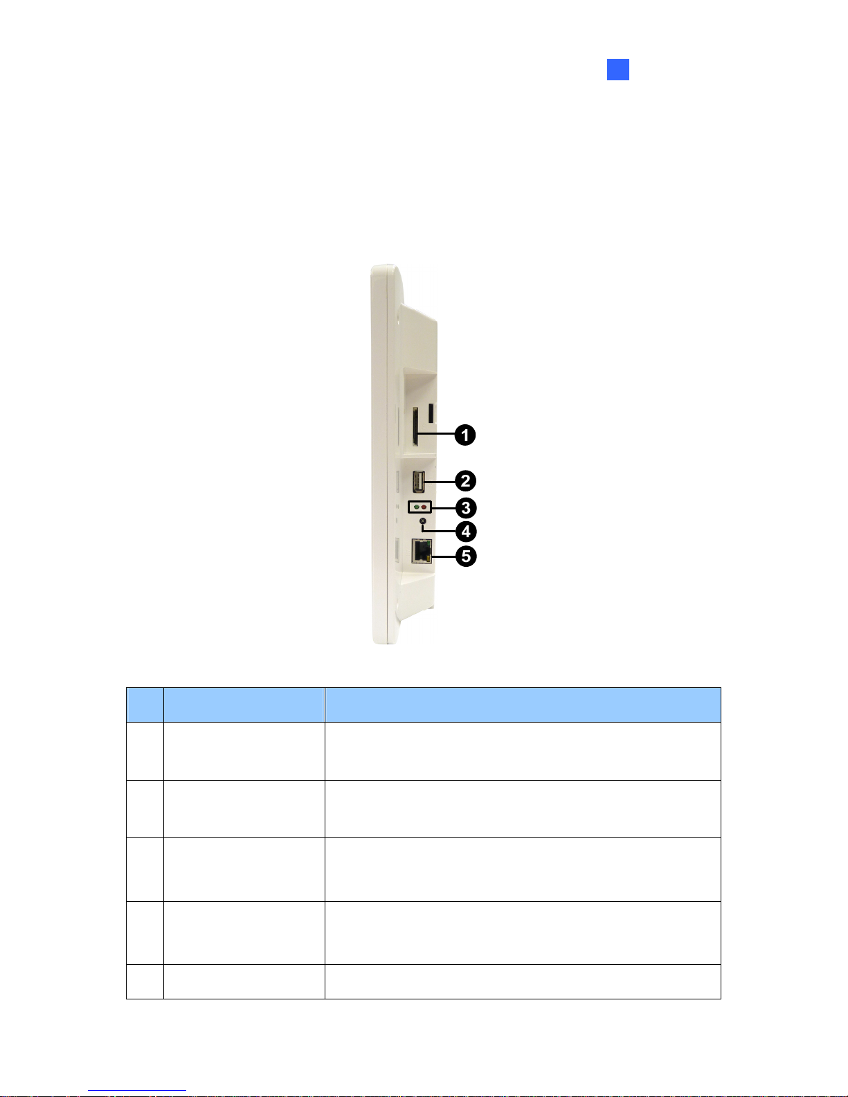
4.5.1 Right Panel View
Figure 4-2
No. Name Function
1 SD Card Slot
Connect to an SD card for local storage of snapshot and
firmware upgrade.
2 USB
Connect to a GV-Joystick, or to a USB storage device for
local storage of snapshot and firmware upgrade.
3 LED Indicators
The green LED indicates the system is ready for use.
The red LED indicates the power is supplied.
4 IR
Built-in IR receiver to receive the IR signals from the IR
remote control.
5 Network Connect to the network.
Page 52
46
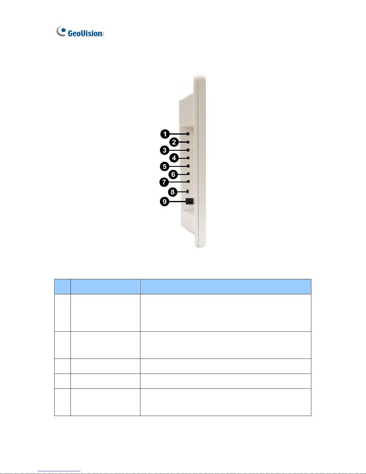
4.5.2 Left Panel View
Figure 4-2
No. Name Function
1.
MENU
z Switch to the setup menu.
z Load default: Press for 10 seconds to load default
settings.
2
ENTER
z Save settings in the Setup Menu.
z Display selected channels.
3
UP
Move the cursor up.
4
DOWN
Move the cursor down.
5
LEFT
z Move the cursor left.
z Unselect a channel on the Device List.
Page 53
Introduction
47
4
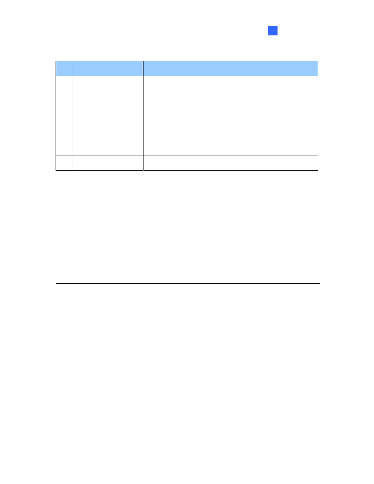
No. Name Function
6
RIGHT
z Move the cursor right.
z Select a channel on the Device List.
7
STAND BY
Press to enter the Standby mode. In the standby mode, the
screen turns off to minimize power consumption. Press the
key again to enter the ON mode.
8
Power OFF/ON
Switch the power on or off.
9
DC 12V
Connect to power using the supplied power adapter.
4.6 The IR Remote Control
The supplied IR remote control for GV-Pad is the same with GV-IP Decoder Box. For the
functions of each key, see 1.6 The IR Remote Control.
Note: The Menu, OK, Arrow, and Power keys on the IR remote control are also available
on the left panel of the GV-Pad. For detail, see 4.5.2 Left Panel View.
Page 54

48
Chapter 5 Getting Started
5.1 Installing the GV-Pad
The GV-Pad can be used as a desktop device, installed on the wall or adhere to a magnetic
surface.
Note: To mount your GV-Pad on the wall, be sure to prepare 4 screws to secure the device
to the wall.
1. Secure the magnetic hinge to the back of the GV-Pad with 4 screws.
2. Adjust the angle of the magnetic hinge according to your needs.
3. To install the GV-Pad on a wall, secure the magnetic hinge with self-prepared screws.
4. Connect the necessary wires and cables. See 5.2 Connecting the GV-Pad.
Page 55
Getting Started
49
5
5.2 Connecting the GV-Pad
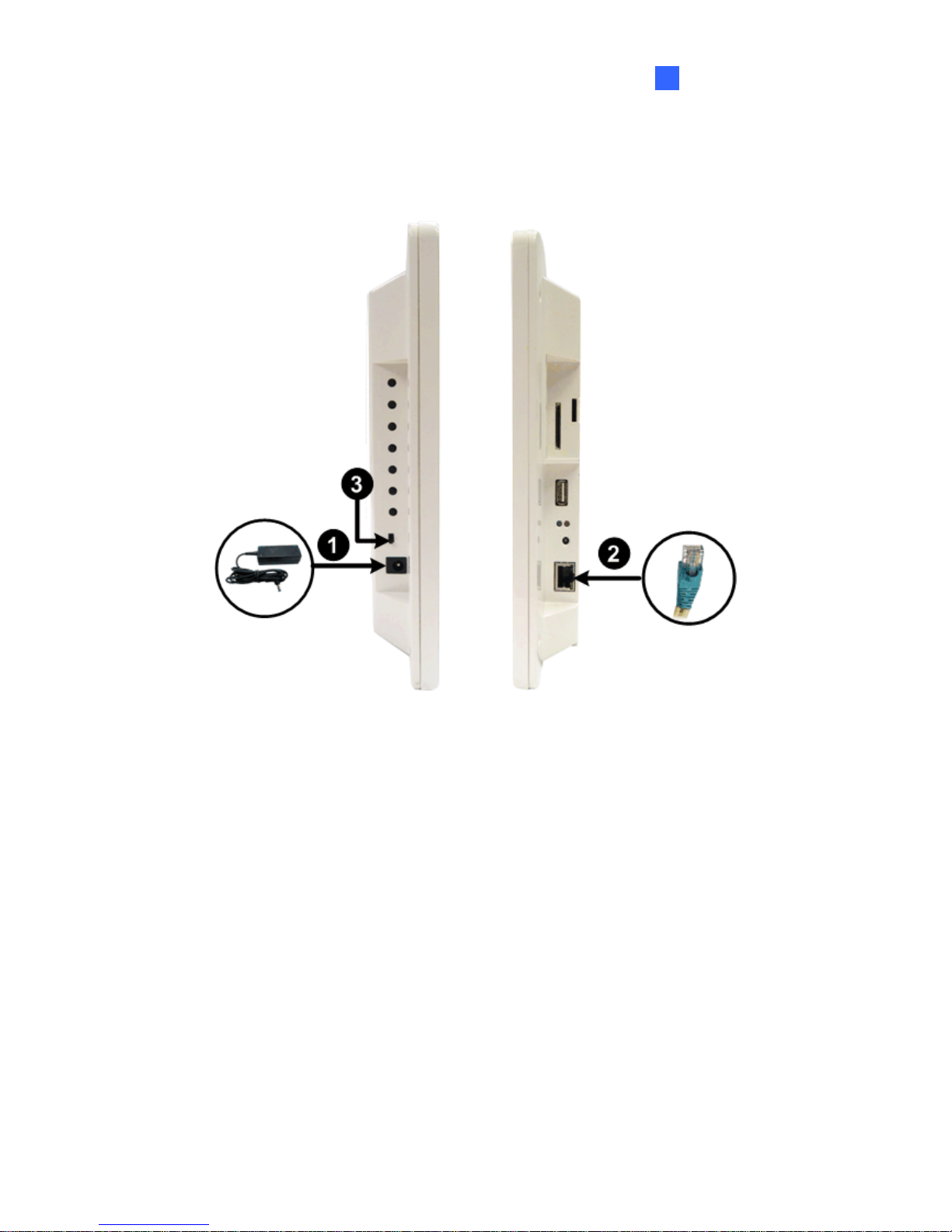
Follow the steps below to connect the GV-Pad:
Figure 5-1
1. Connect to power using the supplied power adapter.
2. Connect to a standard network cable.
3. Turn the Power switch to ON.
Page 56
50
5.3 Configuring the Basics
After you have installed and connected the necessary wire and cable to your GV-Pad, you are
ready to configure the GV-Pad.
1. Configure the IP address, ID and password. See 2.3 Configuring the IP Address, ID and
Password.
Note:
1. Since all the GV IP devices have the default IP address 192.168.0.10. Therefore, it is
strongly advisable to modify the IP address to avoid IP conflict.
2. The default ID and password are admin.
3. The IP devices to be connected need to have the same ID and password set on the
GV-Pad.
2. Display channels. The GV-Pad can display up to 64 IP channels from GeoVision and/or
third-party devices. Refer to the sections indicated below to set up the channels.
Functions Reference
To display channels from GV
IP devices
See 2.4 Displaying Channels from GV IP
Devices
To display channels form
third-party IP devices
See 2.5 Displaying Channels Using GV IP
Device Utility
To display channels connected
to GV-System
See 2.6 Displaying Channels from GV-System
Page 57
Getting Started
51
5
5.4 Managing the GV-Pad
The administrator can take snapshots, pause at a single channel and control PTZ cameras.
Functions Reference
Taking a snapshot See 2.7 Taking a Snapshot
Pausing at a channel See 2.8 Pausing the Lopped View
Controlling PTZ cameras See 2.9 Controlling PTZ Cameras
Page 58
52
Chapter 6 System Setup
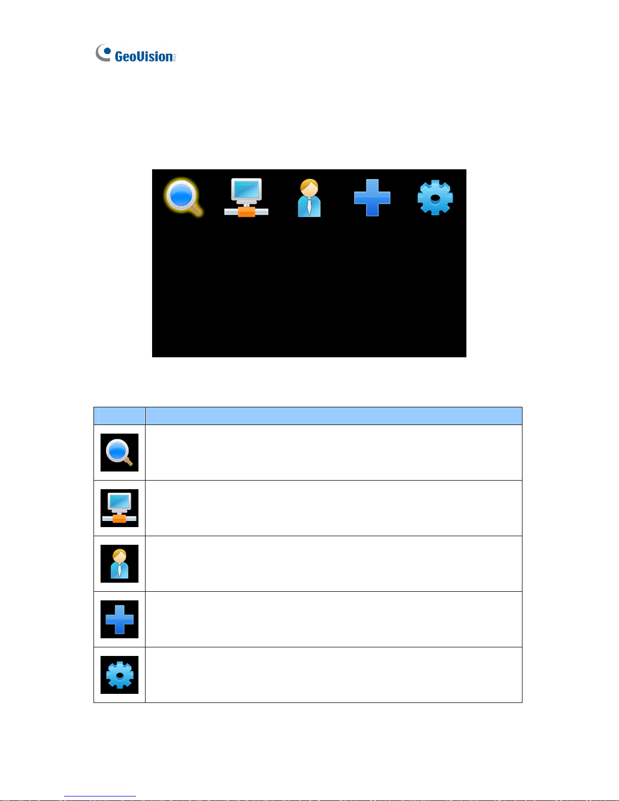
When the GV-Pad is connected and powered on, the main menu appears:
Figure 6-1
Icon Main Functions
Search for GV IP devices and GV-Mobile Server under the same LAN with the
GV-Pad and generates a Device List. For detail, see 3.1 Searching IP Devices.
Contains network settings of the GV-Pad. For detail, see 3.2 Setting the
Network.
Contains the settings for IP devices to be displayed on GV-Pad. For detail, see
3.3 Configuring the Play Mode.
Adds a GV IP device to the Device List and contains sorting options for the
Device List. For detail, see 3.4 Adding a GV IP Device.
Contains settings for account, storage, monitor type, resolution, and firmware
upgrade. For detail, see 3.5 Configuring the Account, Storage and Output Type.
Page 59
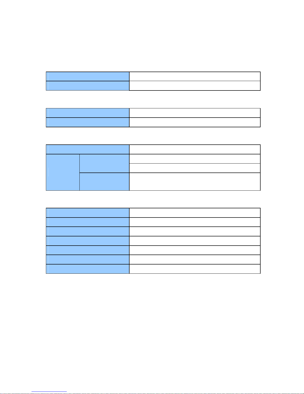
Specifications
53
Specifications
Video
Video Codec H.264
Resolution 1280 x 800
Network
Interface 10/100 Ethernet
Protocol TCP, RTSP, ONVIF, PSIA
Mechanical
IR Remote Control Yes
Power 12V DC Jack
Ethernet RJ-45
Connectors
Local Storage &
Firmware Upgrade
USB slot (2.0 backward compatible, FAT32 format)
SD card slot (for Class 6 card or above, FAT32 format)
General
Operating Temperature 0°C ~ 40°C / 32 °F ~ 104 °F
Operating Humidity 20 % ~ 80 % (with no condensation)
Dimensions (W x H x D) 342.8 × 220.3 × 38.3 mm / 13.5 x 8.7 x 1.5 in
Net Weight 1160 g / 2.6 lb
Power DC 12 V
Power Consumption 36 W (max. 3 A at 12V DC)
Regulatory CE, FCC compliant
All specifications are subject to change without notice.
 Loading...