

Page 1

GEM5000 Gas Analyser
Operating Manual
Geotechnical Instruments (UK) Ltd
Sovereign House
Queensway
Leamington Spa
Warwickshire
CV31 3JR
England
Tel: +44 (0)1926 338111
Fax: +44 (0)1926 338110
Email: [email protected]
Website: www.geotechuk.com
Page 2

OMGEM5KN4 GEM5000 gas analyser
Page 2 Copyright Geotech
This page is intentionally left blank.
Page 3

Table of contents
1.0 MANUAL GUIDELINES ...................................................................................... 6
1.1 Document history ............................................................................................. 6
1.2 Hazard warnings and safety symbols .................................................................. 6
1.3 Notes .............................................................................................................. 6
2.0 INTRODUCTION ............................................................................................... 7
2.1 Safety instructions ............................................................................................ 7
2.2 Instructions for safe use .................................................................................... 8
2.3 MCERTS (applied for) ...................................................................................... 10
2.4 CIRIA ............................................................................................................ 10
2.5 Declaration of conformity ................................................................................ 11
3.0 THE GEM5000 GAS ANALYSER .......................................................................... 14
3.1 The GEM5000 ................................................................................................ 14
3.2 GEM5000 standard product.............................................................................. 15
4.0 GEM5000 OPTIONAL PRODUCTS AND ACCESSORIES ...................................... 17
4.1 Optional products ........................................................................................... 17
4.1.1 Pitot tube (optional) .................................................................................. 17
4.1.2 Orifice plate (optional) ............................................................................... 17
4.1.3 Temperature probe (optional) ..................................................................... 17
4.1.4 Anemometer (optional).............................................................................. 17
4.1.5 H2S filter (optional) ................................................................................... 18
4.1.6 Gas analyser manager – GAM (optional) ...................................................... 18
4.1.7 GPS (optional) .......................................................................................... 18
4.1.8 Bluetooth dongle (optional) ........................................................................ 18
4.2 Instrument accessory products ........................................................................ 19
5.0 GEM5000 INSTRUMENT FEATURES ................................................................. 20
5.1 Physical characteristics of the instrument panel .................................................. 20
5.2 Analyser features and keys .............................................................................. 21
5.3 Instrument connection points ........................................................................... 22
6.0 GENERAL OPERATIONAL INSTRUCTIONS ....................................................... 23
6.1 Switching the instrument on ............................................................................ 23
6.1.1 Power on self-test ........................................................................................ 23
6.2 Switching the analyser off ............................................................................... 23
6.3 Instrument status icons................................................................................... 24
6.4 Instrument LED power states ........................................................................... 25
6.5 Changing between parameters ......................................................................... 25
6.6 Entering data ................................................................................................. 25
6.7 Instrument main gas read screen ..................................................................... 26
6.8 Storage ......................................................................................................... 26
6.9 Battery/charging ............................................................................................ 26
6.10 Cleaning instructions .................................................................................... 27
6.11 Memory ...................................................................................................... 27
6.12 Warning and error codes .............................................................................. 28
7.0 OPERATOR SETTINGS ..................................................................................... 29
7.1 Menu key ...................................................................................................... 29
Page 4

OMGEM5KN4 GEM5000 gas analyser
Page 4 Copyright Geotech
7.2 Device settings .............................................................................................. 29
7.2.1 Date and time .......................................................................................... 29
7.2.2 Bluetooth ................................................................................................. 30
7.2.3 Device information .................................................................................... 31
7.2.4 Diagnostics .............................................................................................. 31
7.2.5 Navigation (optional) ................................................................................. 32
7.3 User settings ................................................................................................. 33
7.3.1 Operating language ................................................................................... 33
7.3.2 Units of measurement ............................................................................... 34
7.3.3 ID selection .............................................................................................. 35
7.3.4 Adjust backlight ........................................................................................ 36
7.3.5 Adjust volume .......................................................................................... 37
7.3.6 User Prompts .............................................................................................. 38
7.4 Operation settings .......................................................................................... 38
7.4.1 Timers ..................................................................................................... 38
7.4.2 Gas Check ............................................................................................... 39
7.4.4 Set alarms ............................................................................................... 41
7.4.5 Adjust flow fail ......................................................................................... 41
7.4.6 Technician login........................................................................................... 42
7.5 Exit menu ...................................................................................................... 43
8.0 TAKING READINGS ......................................................................................... 44
8.1 Preliminary checks before taking readings (best practice) .................................... 44
8.2 Update site data ............................................................................................. 45
8.3 Special action ................................................................................................ 45
8.3.1 Configuration of the data logging option ......................................................... 47
8.3.2 Profiling option ............................................................................................ 47
8.4 GEM analyser in GA mode ............................................................................... 48
8.5 The gas flow measurement screen .................................................................... 48
8.6 How to use an anemometer (optional) .............................................................. 49
8.7 How to use a pitot tube (optional) .................................................................... 52
8.8 How to use an H2S filter (optional).................................................................... 53
8.8.1 Cross gas effects on chemical cells .............................................................. 53
8.8.2 Cross-gas effects on methane, carbon dioxide and oxygen ............................. 54
8.9 How to use a temperature probe (optional) ....................................................... 56
8.10 How to identify a borehole using the GPS feature (optional) .............................. 56
8.11 Taking gas and flow measurement ................................................................. 60
9.0 CALIBRATION ................................................................................................ 61
9.1 Calibration introduction ................................................................................... 61
9.2 Frequency of calibration – best practice ............................................................. 61
9.3 Calibration gases ............................................................................................ 62
9.4 Calibration set-up ........................................................................................... 63
9.5 Calibration equipment ..................................................................................... 63
9.6 Gas analyser .................................................................................................. 64
9.7 Calibration processes – best practice ................................................................ 64
9.7.1 Gas Check in fresh air ............................................................................... 65
9.8 Restore to factory ........................................................................................ 67
9.9 Calibration history .......................................................................................... 67
9.10 Calibration summary .................................................................................... 67
10.0 PROBLEM SOLVING ..................................................................................... 68
11.0 WARNING AND ERROR DISPLAY.................................................................. 68
12.0 SERVICE ...................................................................................................... 69
13.0 WARRANTY POLICY ..................................................................................... 70
14.0 SAMPLE CERTIFICATE OF CALIBRATION ..................................................... 71
Page 5

GEM5000 gas analyser OMGEM5KN4
Copyright Geotech Page 5
15.0 IMPORTANT NOTICE TO ALL CUSTOMERS .................................................... 73
16.0 APPENDICES – SAFETY INSTRUCTIONS ....................................................... 74
16.1 Instructions for safe use – Italian language ..................................................... 74
16.2 Instructions for safe use – German language .................................................. 82
16.3 Instructions for safe use – French language .................................................... 91
16.4 Instructions for safe use – Spanish language ................................................. 101
16.5 Instructions for safe use - Portuguese language ............................................. 110
17.0 GLOSSARY OF TERMS ................................................................................ 112
Page 6
OMGEM5KN4 GEM5000 gas analyser
Page 6 Copyright Geotech
1.0 Manual guidelines
1.1 Document history
Issued
By
Issue
Date
Change
Control ID
Issue
No.
Reason for Change
LA
JAN 2012
OMGEM5KN
1.01
New Instructions.
MS
JULY 2012
OMGEM5KN
1.02
New instructions.
JH
JAN 2013
OMGEM5KN
2
New instructions.
JH
MAR 2013
OMGEM5KN
3
New instructions.
JH
AUG 2013
OMGEM5KN
4
New instructions
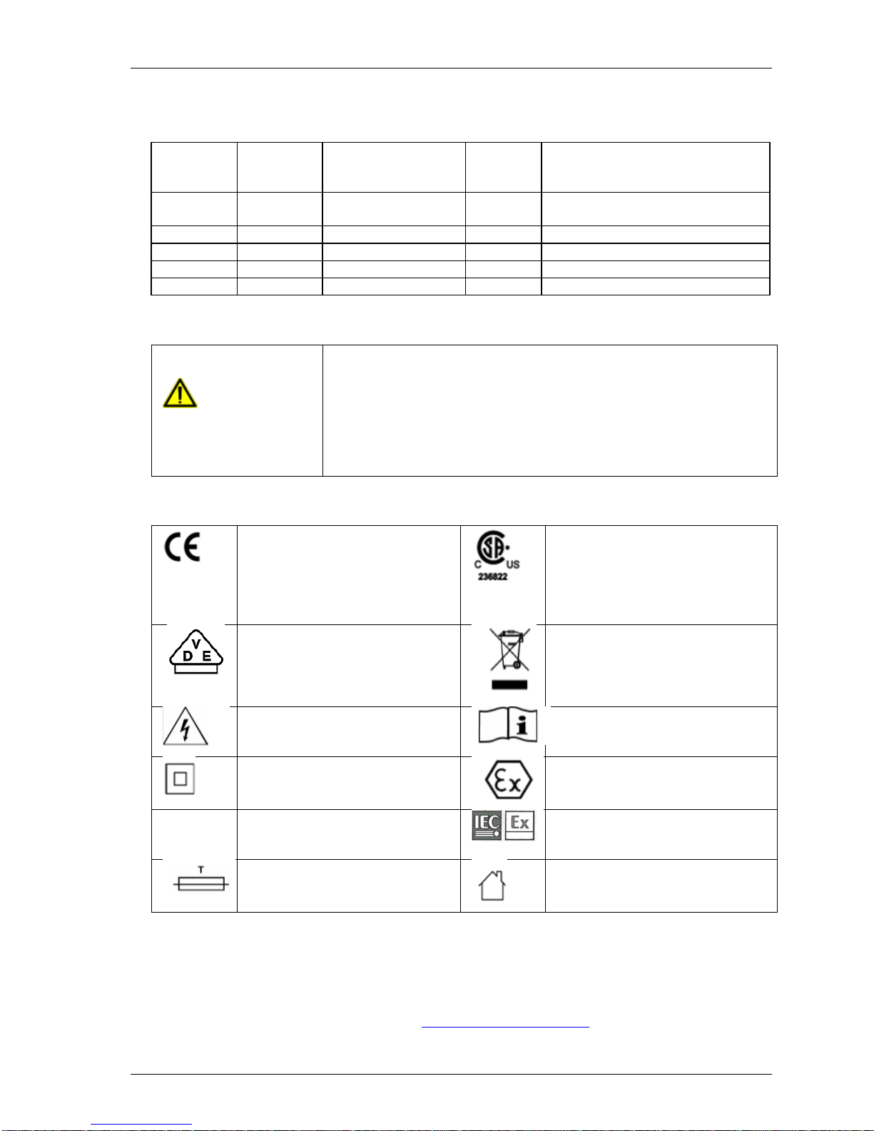
1.2 Hazard warnings and safety symbols
Warning
Information in this manual that may affect the safety of users
and others is preceded by the warning symbol.
Caution - Failure to follow the correct information may result in
physical injury which in some cases could be fatal. If the
equipment is used in a manner not specified by the
manufacturer, the protection provided by the equipment may be
impaired.
General product label symbols are listed as follows:
CE conformity-The CEmarking is the manufacturer's
statement to the EU
authorities that the product
complies with all relevant CEmarking Directives.
If the CSA mark appears with
the indicator "US" or "NRTL" it
means that the product is
certified for the U.S. market, to
the applicable U.S. standards.
VDE mark is a symbol for
electrical, mechanical,
thermal, toxic, radiological
and other hazards.
Separate collection, handling
and disposal for waste electrical
and electronic equipment and
its
components.
Electric shock warning.
Refer to operators manual.
Double insulated construction
- does not require an Earth.
Specific marking of explosion
protection (ATEX only).
II 2G
Equipment group and
category. G = gases; the type
of explosive atmosphere.
IECEx licenced mark
(IECEx only).
Fuse.
Equipment for indoor use only.
1.3 Notes
Important/useful information and instructions are shown clearly throughout the manual in
a note format. For example:
Note: For further information please contact Technical Support at Geotech on
+44(0)1926 338111 or email [email protected]
Page 7

GEM5000 gas analyser OMGEM5KN4
Copyright Geotech Page 7
2.0 Introduction
This manual explains how to use the GEM5000 landfill gas analyser. The GEM5000 has
additional functionality to the GA5000 gas analyser. The GA5000 measures gas
concentrations only, whereas the GEM5000 measures flow and gas concentrations. The
GEM5000 measures flow and calculates the calorific values of the gas as well as being a
useful tool for balancing the gas field. The GEM5000 gas analyser may be used to monitor,
calculate, adjust and record the flow at each monitoring point.
This instrument may also be used in GA5000 mode of operation if required. The operator
may change the analyser between a gas extraction monitor (a GEM5000 gas analyser) or a
landfill gas analyser (a GA5000 gas analyser). The mode of operation can be changed from
the ‘Special Action’ menu. Please refer to section ‘8.0 – Taking Readings’ for further
instruction.
The 5000 series of gas analysers complies with Part 15 of the FCC Rules. Operation is
subject to the following two conditions:
1) This device may not cause harmful interference.
2) This device must accept any interference received, including interference that may cause
undesired operation.
2.1 Safety instructions
Warning
The 5000 series of gas analysers can be used for measuring gases
from landfill sites and other sources as described in this manual.
The operator may be exposed to harmful gases during the use of the
instrument. Inhaling these gases may be harmful to health and in
some cases may be fatal.
It is the responsibility of the user to ensure that he/she is adequately
trained in the safety aspects of the gases being used and appropriate
procedures are followed. In particular, where hazardous gases are
being used the gas exhausted from the analyser must be piped to an
area where it is safe to discharge the gas.
Hazardous gas can also be expelled from the instrument when
purging with clean air.
The instrument has been designed to be used in explosive
atmospheres as defined by the classification. The instrument can be
configured to measure low levels of several gases, but may not be
certified for use in potentially explosive atmospheres of these gases.
It is the responsibility of the operator to determine the protection
concept and classification of equipment required for a particular
application and whether these gases create a potentially explosive
atmosphere.
Note: Gas analysers are a sensitive piece of scientific equipment, and should be
treated as such. If the equipment is used in a manner not specified by the
manufacturer, the protection provided by the instrument may be impaired.
Page 8
OMGEM5KN4 GEM5000 gas analyser
Page 8 Copyright Geotech
2.2 Instructions for safe use
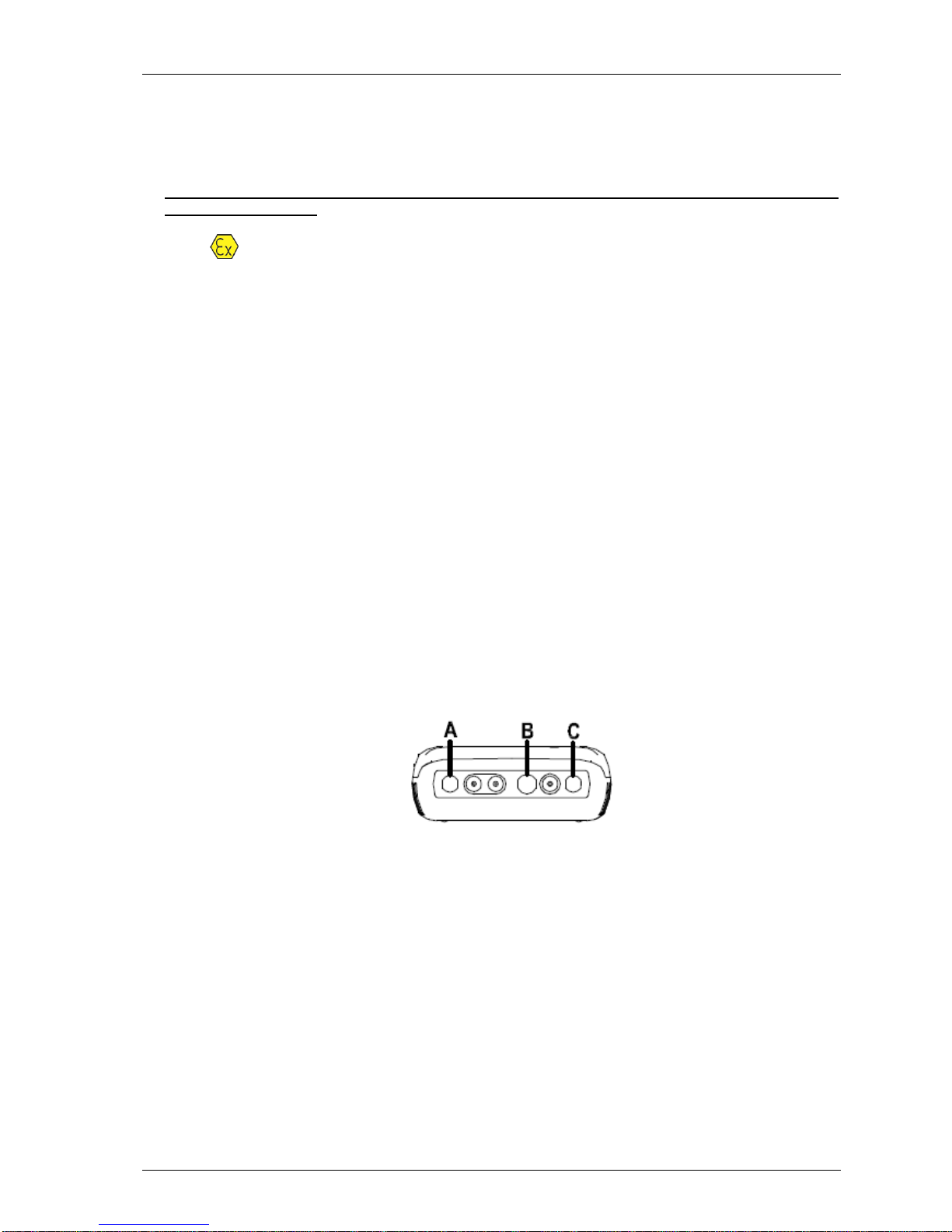
For ATEX and IECEx the 5000 series of gas analysers are certified to Hazardous
Area Classification
II 2G Ex ib IIA T1 Gb (Ta = -10ºC to +50ºC)
It is vital instructions are followed closely. It is the responsibility of the operator to
determine the protection concept and classification required for a particular application.
(Reference European ATEX Directive 94/9/EC, Annex II, 1.0.6)
The following instructions apply to equipment covered by certificate numbers SIRA
11ATEX2197X and IECEx Directive SIR 11.0089X:
The equipment may be used with flammable gases and vapours with apparatus
group IIA and temperature class T1.
The equipment can contain gas sensing heads for the detection of particular gases.
The inclusion of a sensor does not infer that the equipment is suitable for the use of
gases with a temperature class of less than T1.
The equipment is only certified for use in ambient temperatures in the range -10ºC
to +50ºC and should not be used outside this range.
The equipment must not be used in an atmosphere of greater than 21% oxygen.
Repair of this equipment shall be carried out in accordance with the applicable code
of practice.
When used in a hazardous area only use GF5.2 temperature probe (SIRA
11ATEX2197X and IECEx SIR11.0089X). For connector C, the GF5.4 anemometer
(BVS 04ATEXE194) for use with ATEX only. The analyser should not be connected
to any other devices in the hazardous area including the GF-USB lead (connector A)
or GF3.9 battery charger (connector B) supplied with the analyser.
Do not charge, recharge or open in a potentially explosive atmosphere.
In hazardous area only use “Temperature Probe GF5.2” in Connector B.
Connector C (Uo=10V,lo=5mA,Po=50mW,Ci=0,Li=0,Co=100uF,Lo=1000mH),
Connector B (Uo=5V,lo=6mA,Po=7mW,Ci=0,Li=0,Co=100uF,Lo=1000mH)
MAXIMUM NON-HAZARDOUS SUPPLIES:
Connector A - Um=6V Connector B - Um=10.1V
The safe area apparatus that is to be connected to the USB Port shall be a Safety
Extra Low Voltage (SELV) or Protective Extra Low Voltage (PELV) circuit.
Only a Geotechnical Instrument battery pack part number 20087 or 2011113 is
permitted as a replacement. This battery pack shall only be changed in a safe area
by Geotech personnel or authorised distributors.
Only Battery Charger type GF3.9 shall be used to recharge the batteries via
Connector ‘B’.
If the equipment is likely to come into contact with aggressive substances, e.g.
Page 9

GEM5000 gas analyser OMGEM5KN4
Copyright Geotech Page 9
acidic liquids or gases that may attack metals, or solvents that may affect
polymeric materials, then it is the responsibility of the user to take suitable
precautions, e.g. regular checks as part of routine inspections or establishing from
the material’s data sheet that it is resistant to specific chemicals that prevent it
from being adversely affected, thus ensuring that the type of protection is not
compromised.
The relative pressure range is +/-500 mbar. Note, however, that the input pressure
should not exceed +/- 500 mbar relative to atmospheric pressure and the output
pressure should not exceed +/- 100 mbar relative to atmospheric pressure.
For CSA (Canada) the 5000 series of gas analysers are certified to Hazardous
Area Classification
CLASS 2258 03 - PROCESS CONTROL EQUIPMENT - Intrinsically Safe and Non-
Incendive Systems - For Hazardous Locations
Ex ib IIA:
Model GA 5000, GEM 5000 and BIOGAS 5000 Methane Detectors; portable, battery
powered with non-field-replaceable Battery Pack P/N 20087 or 2011113; intrinsically safe
and providing intrinsically safe circuits (“[ib]” for Zone 1) to Model GF5.2 Temperature
Probe (Connector B) and with entity output parameters as tabulated below; Temperature
Code T1; -10 ºC Tamb. +50ºC.
Connector
Entity Parameters
Uo
(V)
Io
(mA)
Po
(mW)
Co
(uF)
Lo
(mH)
Ci
(uF)
Li
(mH)
B
5.0 6 7
100
1000
0 0 C
10.0
5
50
100
1000
0
0
Note: This device has been investigated for electrical safety features only.
For CSA (USA) the 5000 series of gas analysers are certified to Hazardous Area
Classification
CLASS 2258 83 - PROCESS CONTROL EQUIPMENT - Intrinsically Safe and Non-
Incendive Systems – For Hazardous Locations - CERTIFIED TO U.S. STANDARDS
AEx ib IIA:
Model GA 5000, GEM 5000 and BIOGAS 5000 Methane Detectors; portable, battery
powered with non-field-replaceable Battery Pack P/N 20087 or 2011113; intrinsically safe
and providing intrinsically safe circuits (“[ib]” for Zone 1) to Model GF5.2 Temperature
Page 10

OMGEM5KN4 GEM5000 gas analyser
Page 10 Copyright Geotech
Probe (Connector B) and with entity output parameters as tabulated below; Temperature
Code T1; -10 ºC Tamb. +50ºC.
Connector
Entity Parameters
Uo
(V)
Io
(mA)
Po
(mW)
Co
(uF)
Lo
(mH)
Ci
(uF)
Li
(mH)
B
5.0 6 7
100
1000
0
0
C
10.0
5
50
100
1000
0
0
Note: This device has been investigated for electrical safety features only.
2.3 MCERTS (applied for)
MCERTS is the UK Environment Agency's Monitoring Certification Scheme. The scheme
provides a framework within which environmental measurements can be made in
accordance with the Agency's quality requirements. The scheme covers a range of
monitoring, sampling and inspection activities.
The GEM5000 instrument is MCERTS certified only if:
The MCERTS logo appears on the screen after initial power on.
Note: MCERTS - Cross sensitivity tests using hydrogen sulphide were not carried
out on this instrument. Therefore, users should be aware if H2S is present
on sites, as there may be an interferential effect.
MCERTS promotes public confidence in monitoring data and provides industry with a
proven framework for choosing monitoring systems and services that meet the
Environment Agency's performance requirements.
The Environment Agency has established its Monitoring Certification Scheme (MCERTS) to
deliver quality environmental measurements. The MCERTS product certification scheme
provides for the certification of products according to Environment Agency performance
standards, based on relevant CEN, ISO and national standards.
MCERTS certified instruments have been tested by an independent body to ensure that
they meet certain performance requirements. In addition the manufacturer of an MCERTS
product is regularly audited to ensure that the performance requirements of the
certification are being continually met.
The 5000 series of gas analysers have been certified to Version 3.1 of the ‘Performance
Standards for Portable Emission Monitoring Systems’.
2.4 CIRIA
The CIRIA guideline ‘Assessing the risks posed by hazardous ground gases to buildings’
proposes that gas concentrations and flow rates should be monitored.
As an example methodology, they suggest using a gas analyser to first measure flow and
pressure and then afterwards to measure gas concentration.
The logging profile option offers frequency of data to be collected within a timed period
which, in return, identifies a gas profile of the sample point being monitored, information
about whether the sample point is performing correctly, when the peaks occur and
whether air is drawn in after a certain period. This logging option is available on firmware
Page 11
GEM5000 gas analyser OMGEM5KN4
Copyright Geotech Page 11
software version 1.6.5
Versions of the GA5000 analyser range with internal flow on firmware version 1.6.5 and
above have the ability to take measurements according to the CIRIA guidelines, while still
allowing other users to take the measurements as before.
2.5 Declaration of conformity
Products
GA5000 - Landfill Gas Analyser
GEM5000 - Landfill Gas Analyser and Extraction Monitor
BIOGAS 5000 – Anaerobic Digester Gas Analyser
Geotechnical Instruments (UK) Limited declares that the item(s) described above are in
compliance with the following standards:
ATEX Directive 94/9/EC
Certification body
SIRA Certification Service
Notified body number
0518
Address
Rake Lane, Eccleston, Chester, CH4 9JN
SIRA certificate number
SIRA 11ATEX2197X
Standards applied
EN60079-0 :2006
EN60079-0 :2009
EN60079-11 :2007
IECEx
Certification body
SIRA Certification Service
Notified body number
0518
Address
Rake Lane, Eccleston, Chester, CH4 9JN
IECEx certificate number
SIR 11.0089X
Standards applied
IEC60079-0 :2004 Ed4
IEC60079-0 :2007 Ed5
IEC60079-11 :2006 Ed5
CSA (Canada and USA)
Certification body
CSA International
Page 12

OMGEM5KN4 GEM5000 gas analyser
Page 12 Copyright Geotech
Address
178 Rexdale Boulevard, Toronto, ON, Canada M9W 1R3
CSA Certificate number
CSA 11 2445306
Standards applied
C22.2 No. 0-10 - General Requirements – Canadian
Electrical Code, Part II
CAN/CSA-C22.2 No. 60079-0:07 - Electrical apparatus for
explosive gas atmospheres - Part 0: General
Requirements
CAN/CSA-C22.2 No. 60079-1:07 - Electrical apparatus for
explosive gas atmospheres - Part 1: Flameproof
enclosures "d"
CAN/CSA-E60079-11:02 - Electrical apparatus for
explosive gas atmospheres - Part 11: Intrinsic Safety "i"
ANSI/UL 60079-0:09 - Electrical Apparatus for Explosive
Gas Atmospheres - Part 0: General Requirements
ANSI/UL 60079-1:09 - Electrical Apparatus for Explosive
Gas Atmospheres - Part 1: Flameproof Enclosures “d”
ANSI/UL 60079-11:09 - Electrical apparatus for Explosive
Gas Atmospheres - Part 11: Intrinsic Safety “i”
Page 13

GEM5000 gas analyser OMGEM5KN4
Copyright Geotech Page 13
EMC Directive 2004/108/EC
EN 301 489 Pt 1 (V1.9.1 – 2011-04)
EN 301 489 Pt 17 (V2.1.1 – 2009-05)
EN 301 489 Pt 19 (V1.2.1 – 2002-11)
BS EN 61000-3-2: 2006 + A2:2009
BS EN 61000-3-3: 2008
Electromagnetic compatibility
and Radio spectrum Matters (ERM);
ElectroMagnetic Compatibility (EMC)
standard for radio equipment and services;
Part 1: Common technical requirements
Electromagnetic compatibility
and Radio spectrum Matters (ERM);
ElectroMagnetic Compatibility (EMC)
standard for radio equipment;
Part 17: Specific conditions for
Broadband Data Transmission Systems
EMC for broadband data transmission
systems
Electromagnetic compatibility and Radio
spectrum Matters (ERM);
ElectroMagnetic Compatibility (EMC) standard
for radio equipment and services;
Part 19: Specific conditions for Receive Only
Mobile Earth Stations (ROMES) operating in
the 1,5 GHz band providing data
communications
EMC for Receive Only Mobile Earth Stations
(ROMES)
Electromagnetic compatibility (EMC). Limits.
Limits for harmonic current emissions
(equipment input current ≤ 16 A per phase)
Electromagnetic compatibility (EMC). Limits.
Limitation of voltage changes, voltage
fluctuations and flicker in public low-voltage
supply systems, for equipment with rated
current ≤ 16 A per phase and not subject to
conditional connection
Signed:
Dr. Roger Riley
NPI Director and Authorised Person
Page 14
OMGEM5KN4 GEM5000 gas analyser
Page 14 Copyright Geotech
3.0 The GEM5000 gas analyser
3.1 The GEM5000
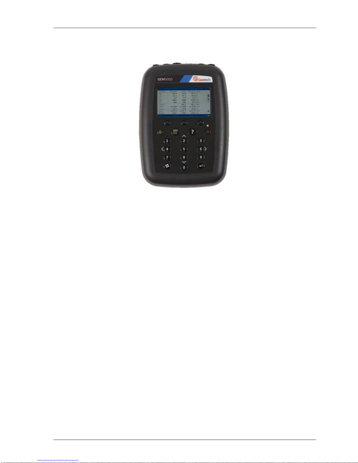
GEM5000 gas analyser
The GEM5000 gas analyser is designed to monitor landfill gas extraction systems.
Benefits:
Allows balancing of gas extraction site.
Maximise power generation from site.
Field proven.
Standardises monitoring routines.
Easy transfer of data.
GPS for compliance.
Features:
ATEX certified.
MCERTS approved.
H2 compensated CO.
Calculates flow (m3/hr) and calorific value (kW or BTU).
Technician log-in.
Event log.
Two instruments in one (GA and GEM mode).
Measures static and differential pressure.
Simultaneous display of gases.
Storage of changes in set-up of gas field.
Data logging.
Applications:
Gas extraction fields.
Flare monitoring.
Landfill sites.
Page 15
GEM5000 gas analyser OMGEM5KN4
Copyright Geotech Page 15
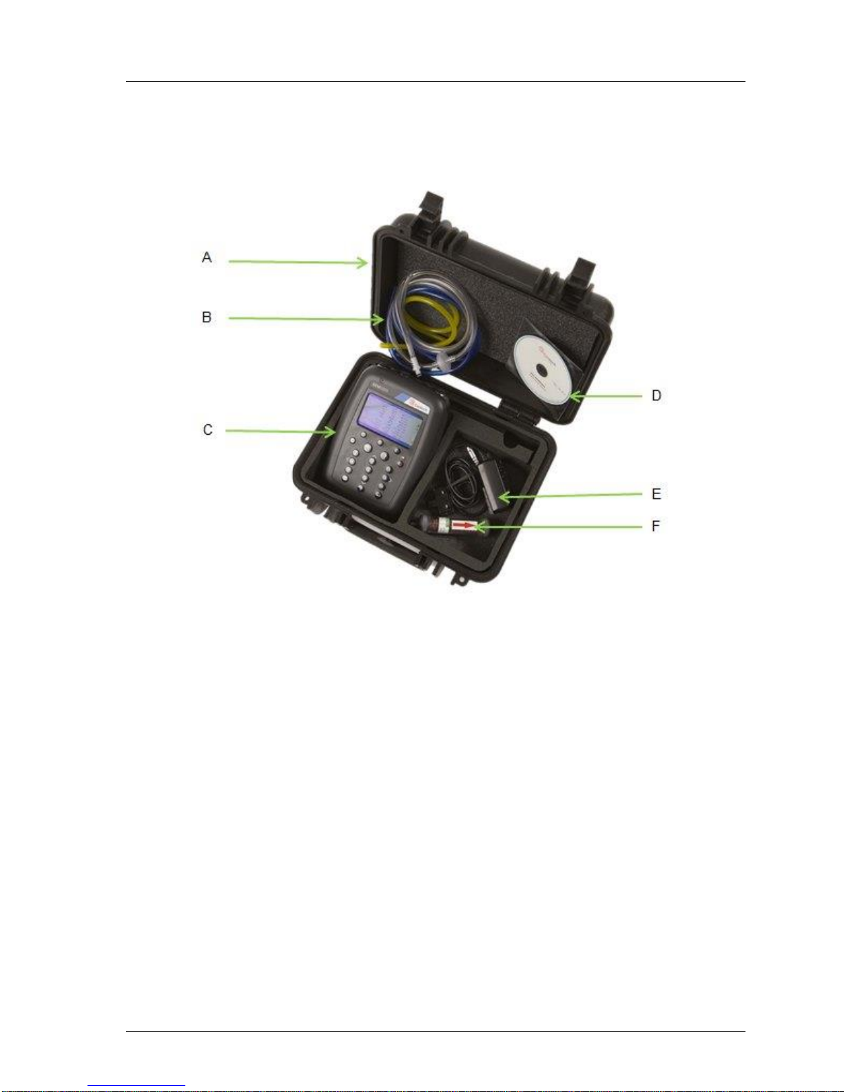
3.2 GEM5000 standard product
GEM5000
Reference:
A
Hard carry case
B
In-line water trap tubing & filter
C
Gas analyser instrument
D
Operating manual CD
E
Mains battery charger and adaptors:
- UK
- Europe
- US
- Australia
F
H2S filter (optional – if the compensated CO cell is fitted)
Page 16

OMGEM5KN4 GEM5000 gas analyser
Page 16 Copyright Geotech
Page 17

GEM5000 gas analyser OMGEM5KN4
Copyright Geotech Page 17
4.0 GEM5000 optional products and accessories
4.1 Optional products
The GEM5000 gas analyser has a number of optional products for purchase which enhance
the usability and enable further analysis of data and reading information.
Note: For more information on the features listed in this section please contact Sales at
Geotech on +44(0)1926 338111 or email [email protected].
4.1.1 Pitot tube (optional)
The GEM5000 gas analyser enables the use of a pitot tube to aid accurate flow
measurement. The pitot tube is used for gas extraction systems and the pressure
readings are taken in mbar. High gas flow is calculated in the analyser in m3/hr (metres
cubed per hour).
4.1.2 Orifice plate (optional)
Geotech recommends the use of orifice plates as good practice when using the GEM5000
gas analyser, enabling repeatability in flow measurement via a fixed method. Orifice
plates are a specialised product and configuration and Geotech does not currently
manufacture or sell spare parts for this product. Please refer to a specialist supplier if
the use of Orifice plates is required.
4.1.3 Temperature probe (optional)
The GEM5000 gas analyser has the facility to automatically display and record the
borehole temperature via an optional temperature probe.
When a temperature probe is fitted the temperature reading will be displayed on the
‘Main Gas Read Screen’ and recorded with all other data.
Note: Temperature probes with an Ex label are part of the GEM5000 Ex certification
SIRA 11ATEX2197X and IECEx SIR11.0089X, and therefore certified for use
under the same conditions as the analyser.
4.1.4 Anemometer (optional)
The GEM5000 gas analyser has the facility to automatically display and record high flow
via an optional anemometer probe. It is designed to plug into the instrument and
instantly provide a flow indication. An anemometer probe adds flow measurements to
the professional reporting ability of the GEM5000 range along with gas concentrations,
pressure and temperature.
The anemometer has a simple connection, a narrow diameter measurement head
(11mm), a wide temperature operating range (up to 80oC) and indicates flows up to 40
m/sec.
When an anemometer probe is fitted to the analyser the flow will be displayed in the
‘Main Gas Read Screen’ and recorded with all other data.
Flow can be measured in either m/s (gas velocity) or m3/hr (volume flow rate). In order
to calculate the volume flow rate the pipe diameter will need to be entered into the
instrument, either manually or via the Gas Analyser Manager software.
Note: The anemometer probe is part of the analyser Ex certification BVS 04ATEXE194
for use with ATEX only and is therefore certified for use in a potentially
Page 18

OMGEM5KN4 GEM5000 gas analyser
Page 18 Copyright Geotech
explosive atmosphere. To use the m3/hr option the firmware software within
the analyser must be set at the time of manufacture.
4.1.5 H2S filter (optional)
The GEM5000 gas analyser has the capability to use an H2S filter and is required as
standard if the compensated CO cell is fitted and configured at the time the instrument is
manufactured. H2S gas can have a cross-gas effect on the CO reading. By using a filter,
the H2S is removed from the gas sample, therefore providing a more accurate CO
reading.
The filter only needs to be used when you are trying to get rid of any possible cross gas
effects H2S might have on other gases. Do not use the filter on all boreholes.
4.1.6 Gas analyser manager – GAM (optional)
Gas Analyser Manager (GAM) enables the operator to maximise the operation of the gas
analyser. It enables direct communication with the unit, features a simple upload and
download facility and is fully compatible with the latest Microsoft™ operating systems.
Features:
Organisation and transfer of borehole IDs and readings to and from the gas
analyser.
Configuration of the gas analyser.
Flexible grouping of the IDs.
Structured organisation of transferred data.
Automatic detection of instrument type and available options.
Secure data mode to prevent tampering.
First time set-up wizard.
Enable flow measurements for GEM5000 gas analysers.
4.1.7 GPS (optional)
An optional GPS feature is available for the GEM5000 gas analyser. It enables the site
engineer to automatically locate borehole IDs using GPS satellite signal from predefined
borehole IDs uploaded from Gas Analyser Manager or set on the analyser when out in the
field prior to taking a reading. The GPS reading data is stored for each measurement
reading providing an audit trail confirming that a reading was taken.
4.1.8 Bluetooth dongle (optional)
An optional Bluetooth feature enables the operator to set and utilise Bluetooth
technology. This may be useful when downloading gas readings from the analyser to the
PC instead of connecting the analyser to a PC via a USB lead. Bluetooth may also be
used to transfer Site IDs to other 5000 series gas analysers if required. Bluetooth is
activated by plugging the dongle into a pc USB port and switching on the Bluetooth
option feature in the settings on the analyser.
Page 19
GEM5000 gas analyser OMGEM5KN4
Copyright Geotech Page 19
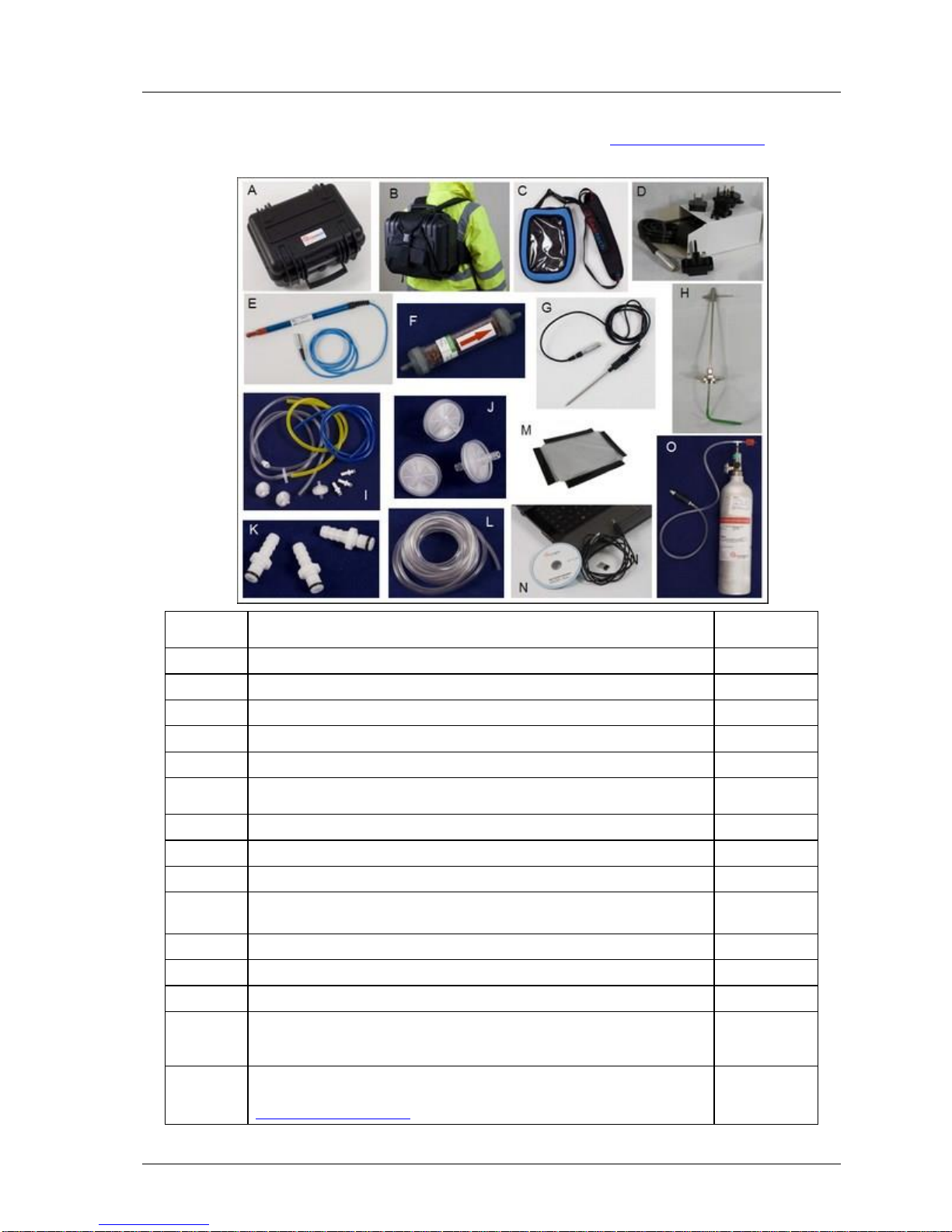
4.2 Instrument accessory products
Optional accessory and replacement parts must ONLY be purchased for the GEM5000 gas
analyser direct from Geotech or your agent. Please contact [email protected] for
further details on pricing and how to order.
Ref
Description
Order
Code
A
Hard carry case
GF2.5
B
Hard carry case backpack (hard carry case not included)
GF2.6
C
Soft carry case
GF5.1
D
Battery charger and adaptors
GF3.9
E
Anemometer (ATEX certified)
GF5.4
F
H2S/Hydrocarbon filters
H2S/Hydrocarbon filters (pack of 5)
GF6.4
GF6.5
G
Temperature probe (ATEX certified)
GF5.2
H
Pitot tube kit
PITOT
I
In-line water trap filter & tubing
GF1.8
J
Water trap with barbed filters (pack of 10)
Water trap with barbed filters (pack of 30)
GA4.9
GA4.9(30)
K
Gas ports connectors (pack of 10)
MC10
L
Sampling tube 5m length flexible PVC tubing (3/16”id)
GA2.3
M
Spare window for the soft carry case
GF5.3
N
Gas Analyser Manager (GAM)
USB lead
Bluetooth dongle
GAM
GFUSB
BLUEDON
O
Check gas regulator and tubing for calibration gas.
Calibration gas canister. Please contact
[email protected] for gas canister concentrations
GA6.8
Page 20
OMGEM5KN4 GEM5000 gas analyser
Page 20 Copyright Geotech
5.0 GEM5000 instrument features
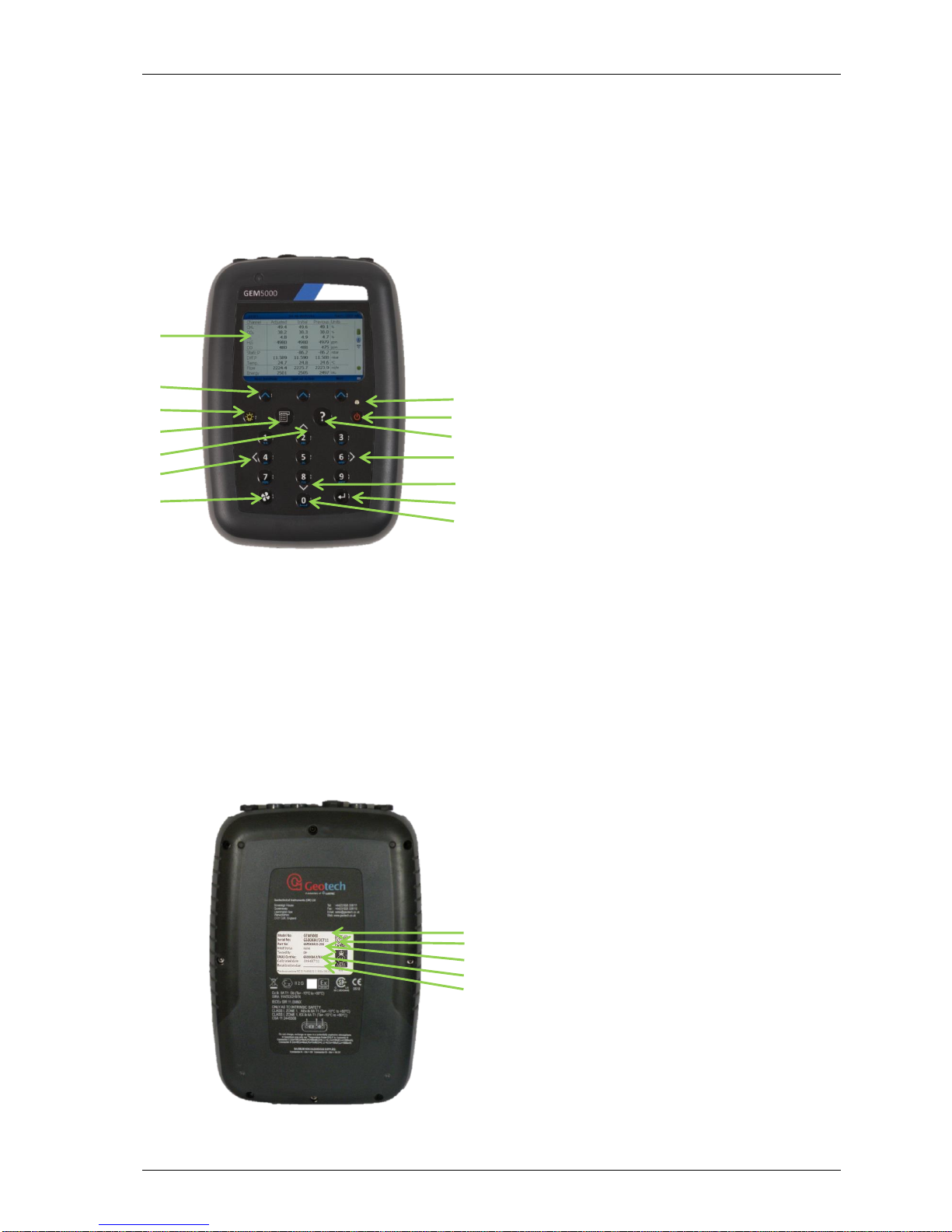
5.1 Physical characteristics of the instrument panel
Front view: Reference:
Back view: Reference:
A
Main Gas Read Screen
B
Soft-keys
C
Backlight Key
D
Menu Key
E
Key 2 – Page Up
F
Key 4 – Scroll Left
G
Pump Key
H
I
LED Light
On/Off Key
J
Assistance Key
K
Key 6 – Scroll Right
L
Key 8 – Page Down
M
Enter Key
N
General Keys
O Model Number
P
Serial Number
Q
R
S
Part Number
Certification Number
Recalibration Due
A
B C D G E F I H J K L M N
O
P Q R
S
Page 21

GEM5000 gas analyser OMGEM5KN4
Copyright Geotech Page 21
5.2 Analyser features and keys
Ref
Feature
Function
A
Main Read Screen
Start and end screen when using the instrument.
B
Soft-keys
The function of the three ‘soft-keys’ on the front of
the instrument panel is determined by menu
options taken. Functions vary from screen to
screen.
C
Backlight Key
Enables the operator to backlight the analyser
display panel.
D
Menu Key
Press the ‘Menu’ key to view and maintain User,
Device and Operation settings.
E
Page Up Key
Also ‘Key 2’. Press scroll up to view further
information on the instrument screen.
F
Scroll Left Key
Also ‘Key 4’. Enables the operator to scroll left to
display more information.
G
Pump Key
Press the ‘Pump’ key to start or stop the pump.
H
I
LED Light
On/Off Key
LED power light is visible on the front of the
analyser when the instrument is powered on.
Press the ‘On/Off’ key briefly to switch the
instrument on and off.
J
Assistance Key
Press the ‘Assistance’ key to view help text
relevant to the analyser screen you are currently
displaying.
K
Scroll Right Key
Also ‘Key 6’. Press scroll right to view further
information on the instrument screen.
L
Page Down Key
Also ‘Key 8’. Enables the operator to scroll down
to display more information.
M Enter Key
The ‘Enter’ key accepts/confirms choices made by
the operator. Also required to confirm numeric
data entry.
N
O
General Keys
Model Number
Keys 0, 1, 2, 3, 4, 5, 6, 7, 8, 9
Instrument model type identification.
P Serial Number
Unique identification for the instrument.
Verification of the serial number will be required if
Technical Support assistance is needed.
Q
R
S
Part Number
Certification Number
Recalibration Due
Manufacturer part number.
Displays instrument certification information.
The date displayed is the date the instrument is
due to be calibrated.
Page 22
OMGEM5KN4 GEM5000 gas analyser
Page 22 Copyright Geotech
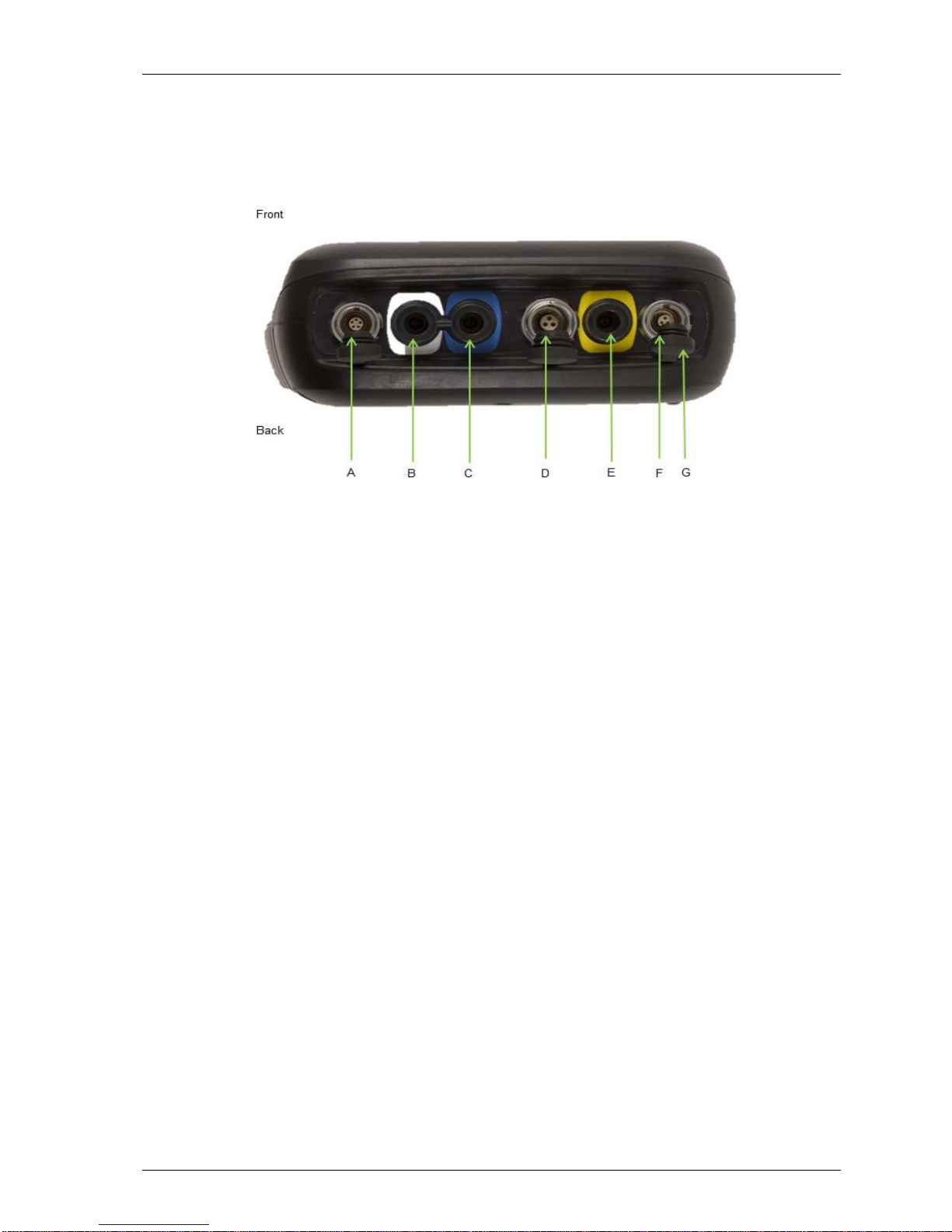
5.3 Instrument connection points
Top view:
Ref:
Connection Point:
Function:
A
Connector A
Attach the USB lead for PC-to-analyser
connectivity.
B
Inlet Port & Static Pressure Port
(White port)
Attach the sample tube to take a gas sample.
Also used to measure the static pressure.
C
Differential Pressure Port
(Blue port)
Attach the sample tube to measure
differential pressure.
D
Connector B
Attach the temperature probe and also used
to attach the mains charger to the analyser
for charging.
E
Gas Outlet Port
(Yellow port)
The gas outlet port is the point at which the
sample gas is expelled. Tubing may also be
attached to the port.
F Connector C
Attach the anemometer.
G
Dust Caps
Dust caps used to protect the connector
points of the instrument.
Page 23

GEM5000 gas analyser OMGEM5KN4
Copyright Geotech Page 23
6.0 General operational instructions
6.1 Switching the instrument on
1) To switch on the analyser, press and hold the ‘On/Off’ key. The Geotech logo will
display followed by the instrument warm up.
2) Following the instrument warm up, the ‘Date and Time’ screen is displayed
prompting the technician to set the date and time and required format.
3) When complete select the soft-key to ‘Exit’ and the ‘Power On Self-test’ screen is
displayed followed by instrument status. Instrument status displays the instruments
service due date, serial number, options, service scheme and software version. Text
will also display stating ‘Self-test complete’.
4) Select the soft-key ‘Next’ to move onto the next screen and the ‘Technician Login’
screen is displayed.
5) Use the cursor keys to move through the list of ID’s. Select either the required
‘Technician ID’ from the list followed by the soft-key ‘Accept’, or select ‘Default’’
followed by the soft-key ‘Accept’ to continue to the ‘Main Gas Read Screen’.
Note: The selected technician ID is displayed at the top left corner of the Main
Gas Read Screen.
6.1.1 Power on self-test
When switched on, the read-out will perform a pre-determined self-test sequence. During
this time many of the analyser’s functions are tested, including:
General operation
Gas flow measurement
Calibration
Backlight function
Battery charge level
During the self-test the following information is also displayed:
Manufacturer’s service due date
The last gas check date
Software version programmed
Date format
Serial number
Operating language
The currently enabled sales option
Note: The self-test should only be done with the analyser sampling fresh air.
6.2 Switching the analyser off
1) To switch off the analyser, press and hold the ‘On/Off’ key, at which point a clean air
purge will be carried out and the instrument will then switch off.
2) If for any reason the analyser ‘locks up’ and will not switch off in this manner, press
and hold the ‘On/Off’ key for 15 seconds; this will force the instrument to switch off.
Page 24
OMGEM5KN4 GEM5000 gas analyser
Page 24 Copyright Geotech
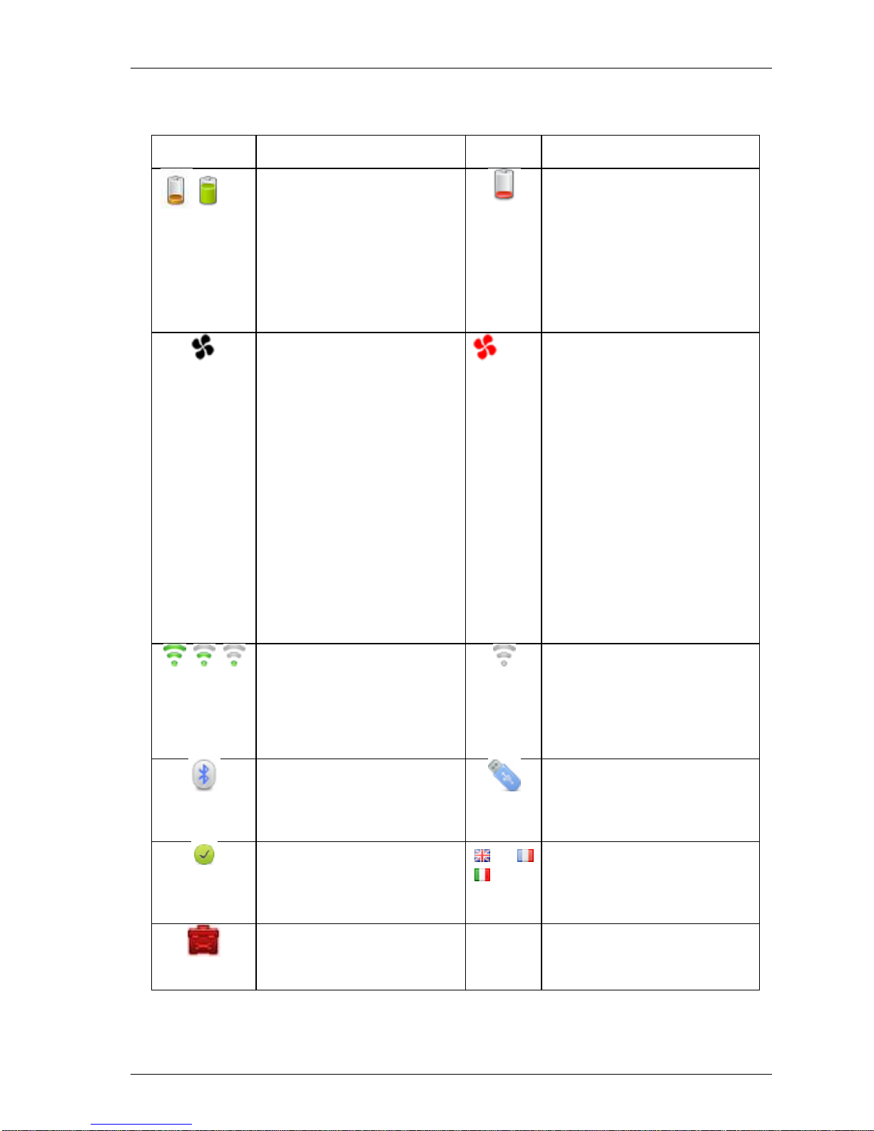
6.3 Instrument status icons
The following icons may be displayed on the instrument screen:
Icon
Description
Icon
Description
Battery charge state
Gives the operator an
estimation of the battery
charge state. For example
100% gives about 8 hours
use in the field and 50%
would mean that there is
approximately 4 hours
battery life remaining.
Battery charge state
Indicates less than 1 hour of
charge remaining.
Pump status
This icon is displayed along
with a counter showing the
pump run-time. This counts
down where the operator
has specified the pump runtime; if not it counts up; the
icon turns red when stalled.
Pump stalled
This icon is displayed when
the pump stalls. The
instrument’s gas inlet (or
outlet) may be blocked. This
warning is most commonly
caused by a water-logged or
dirty sample filter. Change
the sample filter and check
for obvious blockages in the
sample tubes. Alternatively, a
small amount of adjustment
can be made to the low flow
detection point to
compensate for minor
changes in the performance
of the pump fitted to the
instrument.
GPS signal strength
This icon shows the signal
strength the analyser’s GPS
module is able to provide.
Full, okay and fair strength
respectively.
GPS failure
The GPS was unable to get a
line of sight lock on enough
satellites. Or, it may be that
it hasn’t had time to get a
lock.
This indicates when
Bluetooth has been enabled.
The colour changes from
grey to blue when
connected.
USB connected to PC (flickers
when transferring data)
Analyser Health Check
(tba)
Language
This icon indicates the
currently selected operating
language. This can be
changed via the main menu.
Service overdue
This icon indicates that the
analyser is overdue for
service.
Page 25

GEM5000 gas analyser OMGEM5KN4
Copyright Geotech Page 25
6.4 Instrument LED power states
When the instrument is powered on a LED power light is visible on the front of the
analyser, located above the ‘On/Off’ key. The following LED power light states are as
follows:
Steady yellow
Unit turning on. This will extinguish when software has loaded
correctly.
Flashing (rapid)
Unit is powering off.
Flashing (slow)
Power off is being delayed for purge/shutdown handling.
Flashing yellow
Unit is turning off due to power button being pressed.
Flashing red
Unit is turning off due to critically low battery.
Note: Pressing and holding the power button for ~20s resets the analyser.
6.5 Changing between parameters
By default, the instrument displays the ‘Main Gas Read Screen’ (for gas measurement).
The instrument will return to this screen after power on or when returning from the
menus. The ‘Scroll’ keys can be used to switch to another measurement screen.
6.6 Entering data
During normal operation the operator may be prompted to enter data or information via
the keypad, i.e. entering an ID code or setting an alarm level.
When entering data into the instrument all fields are fixed format and are populated from
the left.
Text:
Entering text uses similar multi-tap functionality as a mobile phone. Key the
numeric/alpha key pad the required number of times to select the appropriate letter. To
key numeric data continue to press the numeric/alpha key until the required number is
displayed.
Numeric data:
To enter a new date 09/11/11 the operator would type in 091111 using the numeric
keypad in the following sequence:-
* 0_/__/__
* 09/__/__
* 09/1_/__
* 09/11/__
* 09/11/1_
* 09/11/11
Press the ‘Enter’ key to confirm/accept data keyed.
Any mistakes can be corrected using the soft-key ‘Delete’ which will delete the last digit
typed. Alternatively, the sequence can be retyped before the ‘Enter’ key is pressed and
the existing numbers will be pushed off the screen.
Page 26
OMGEM5KN4 GEM5000 gas analyser
Page 26 Copyright Geotech
Note: The instrument will not allow invalid data to be entered; this should be deleted
and re-entered.
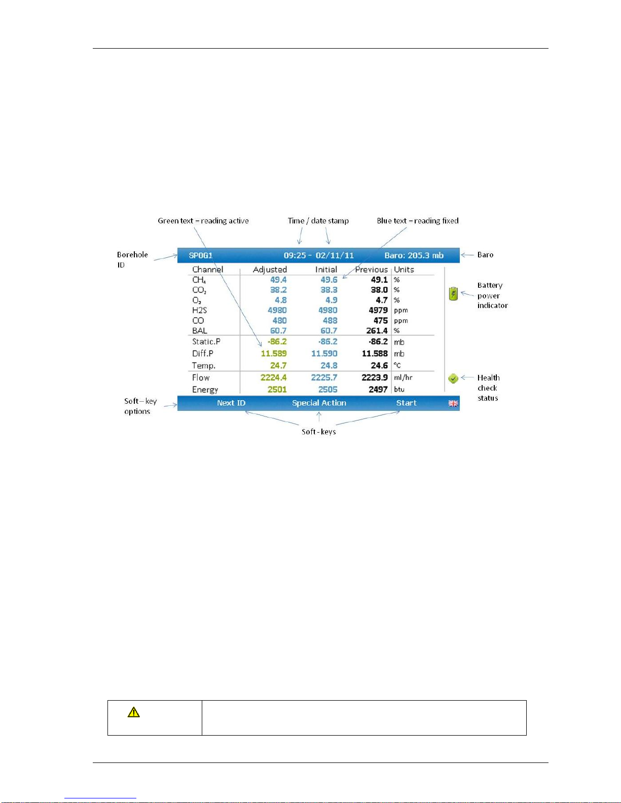
6.7 Instrument main gas read screen
The ‘Main Gas Read Screen’ is considered to be the normal operating screen and all
operations are carried out from this starting point.
The actual data shown on this display will depend on the version of the instrument and the
options that have been selected. In general, all of the main readings will be shown.
6.8 Storage
The analyser should not be exposed to extreme temperature. For example, do not keep
the analyser in a hot car. When not in use analysers should be kept in a clean, dry and
warm environment, such as an office and protect the analyser with either the soft carry
case or store in the hard carry case provided with the instrument.
The instrument should be discharged and fully charged at least once every four weeks,
regardless of indicated charge state.
6.9 Battery/charging
The battery used in the 5000 series of gas analysers is nickel metal hydride and
manufactured as a pack from six individual cells. This type of battery is not so susceptible
to the top-up charging ‘memory effects’ as nickel cadmium batteries, although it is not
recommended that the unit is given small top-up charges.
Note: To reach optimum charge, it is recommended that the instrument is
switched off when being charged and remains switched off during the
charging process.
A full charge will take approximately 4 hours from a fully discharged battery.
Warning
The battery charger is NOT covered by the Ex certification.
The battery must be charged only in a safe area.
Page 27
GEM5000 gas analyser OMGEM5KN4
Copyright Geotech Page 27
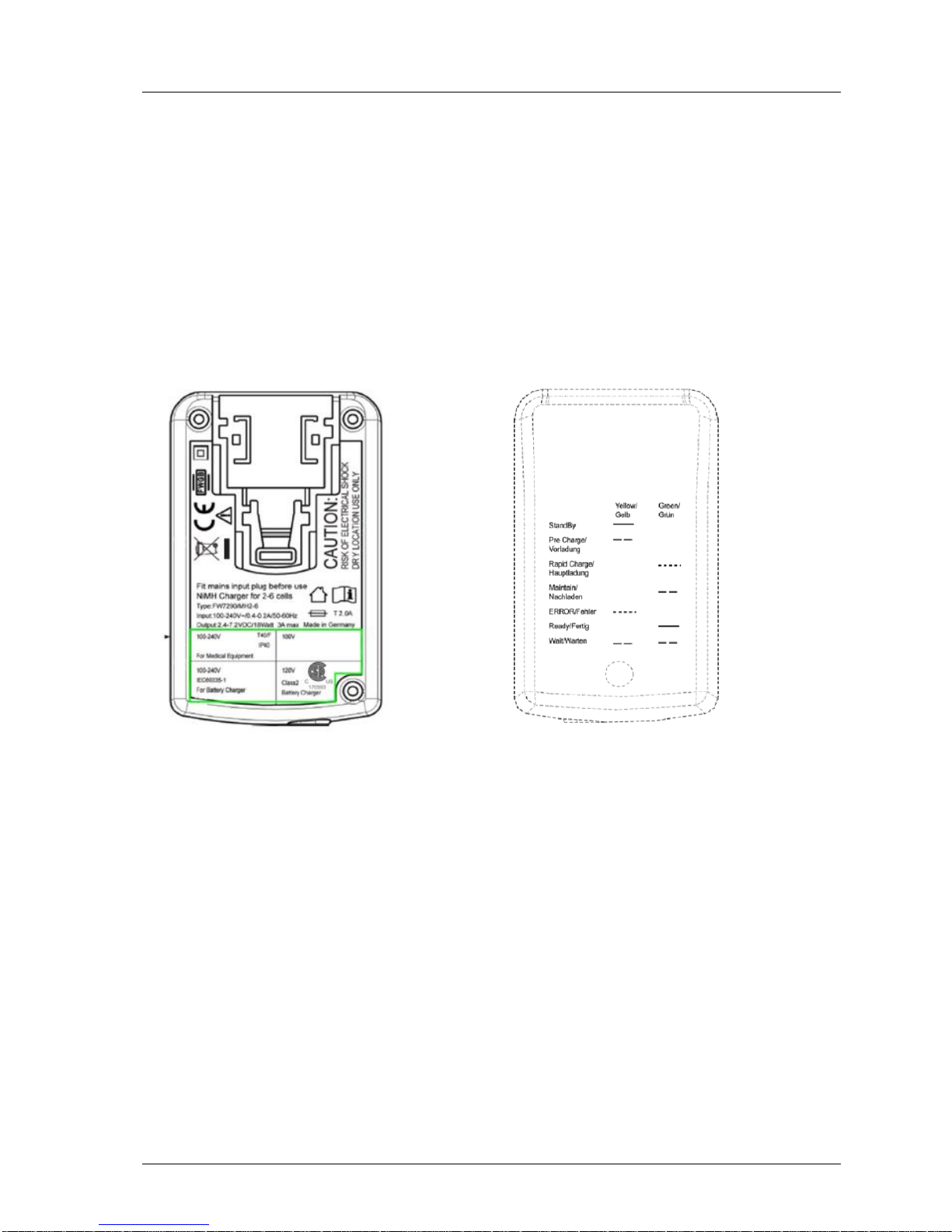
The battery charger is intelligent and will indicate when the unit is charging and charged.
The instrument must be charged ONLY using the battery charger supplied with the
instrument. The battery charger supplied is intended for indoor use only. Please ensure
adequate ventilation whilst charging. Typically, a fully charged battery will last 7-8 hours.
A quick 30 minute charge can be used to give approximately one hours use in the field but
this may shorten the battery life. Temperature can dramatically affect the battery life;
please take this into account when estimating battery life.
Note: Connect the charger to the mains attaching the appropriate adaptor.
Power supply front and back drawing:
Charger: Input voltage: 100-240V AC +/- 10%
Input frequency: 50-60Hz +/- 10%
Input current: 0.4A@100VAC .. 0.2A@240VAC
Output voltage: 10.1VDC max
Output current: 1.5A max
Note: This charger has been internally restricted to 1.5A
6.10 Cleaning instructions
Do NOT use any cleaning agents to clean the analyser or battery charger as they may
have an adverse effect on the safe use of these devices.
6.11 Memory
The analyser's memory is stored in a readings and configuration database.
Note: The analyser should never be stored for prolonged periods with valuable data in
Page 28

OMGEM5KN4 GEM5000 gas analyser
Page 28 Copyright Geotech
its memory. It is advisable to download all readings to GAM at the end of each
day’s monitoring. To clear the memory, please refer to the Gas Analyser
Manager (GAM) operating manual.
6.12 Warning and error codes
When switched on the instrument will perform a predetermined self-test sequence taking
approximately ten seconds. During this time many of the instrument’s working parameters
and settings are checked. If any operational parameters are out of specification or if the
pre-programmed recommended calibration/service date has passed, errors or warnings
may be displayed.
Note: For further information please refer to section ‘10.0 Problem Solving’.
Page 29
GEM5000 gas analyser OMGEM5KN4
Copyright Geotech Page 29
7.0 Operator settings
7.1 Menu key
The ‘Menu’ key enables the operator to select options to set up specific
parameters and perform operational tasks prior to sample readings being
taken or to view data and information stored in the instrument.
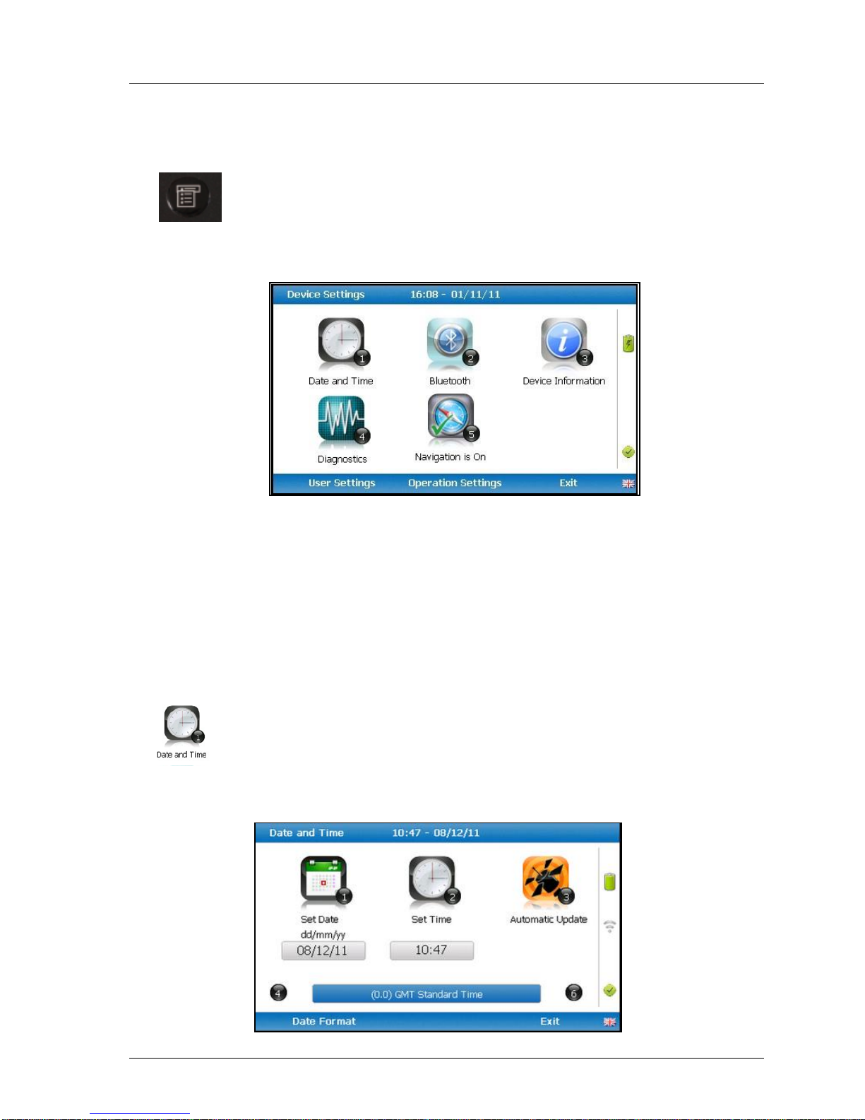
1) Select the ‘Menu’ key on the front of the analyser and the following screen is
displayed:
Device Settings
2) Press the relevant numeric key on the analyser keypad to select the required option.
3) To exit this menu, select the soft-key ‘Exit’ on the front of the analyser and the
operator is returned to Main Gas Read Screen.
7.2 Device settings
7.2.1 Date and time
This option enables the operator to set the instrument date and time or to
receive and update the settings automatically from satellite signal.
1) Select the ‘Menu’ key on the front of the analyser to display the ‘Device Settings’
menu followed by ‘Key 1 – Date and Time’ and the following screen is displayed:
Page 30
OMGEM5KN4 GEM5000 gas analyser
Page 30 Copyright Geotech
2) Select ‘Key 1 – Set Date’ and key in the required date. Type the date using the
numeric keypad. Press the soft-key ‘Date Format’ to toggle and select the required
date format i.e. dd/mm/yy. Press the ‘Enter’ key to confirm and update the date
setting.
3) Select ‘Key 2 – Set Time’ and key in the required time (hh:mm). Type the time
using the numeric keypad and press the ‘Enter’ key to confirm the update.
4) The operator may also change the default time zone. Selecting the ‘Key 4 Scroll-
left’ or ‘Key 6 – Scroll right’ to move through the different time zones. Press the
‘Enter’ key to confirm your default setting.
5) Select ‘Key 3’ to toggle between ‘Manual Update’ and ‘Automatic Update’ in order to
choose how the date and time is set if updating from satellite signal.
Manual
Used to manually obtain and update the date and time from the
satellite signal when requested. Select soft-key ‘Set now’ to set
date and time from satellite when available.
Automatic
Used to automatically update the date and time received from the
satellite signal when available. This option is only available when
the GPS option is fitted to the analyser at the time of
manufacture.
6) Select the soft-key ‘Exit’ to exit and return to the ‘Device Settings’ menu.
7.2.2 Bluetooth
This option enables the operator to utilise Bluetooth technology. This
may be useful when downloading gas readings from the analyser to the
PC instead of connecting the analyser to a PC via a USB lead. Bluetooth
may also be used to transfer Site IDs to other 5000 series gas analysers
if required.
1) Select the ‘Menu’ key on the front of the analyser to display the ‘Device Settings’
menu.
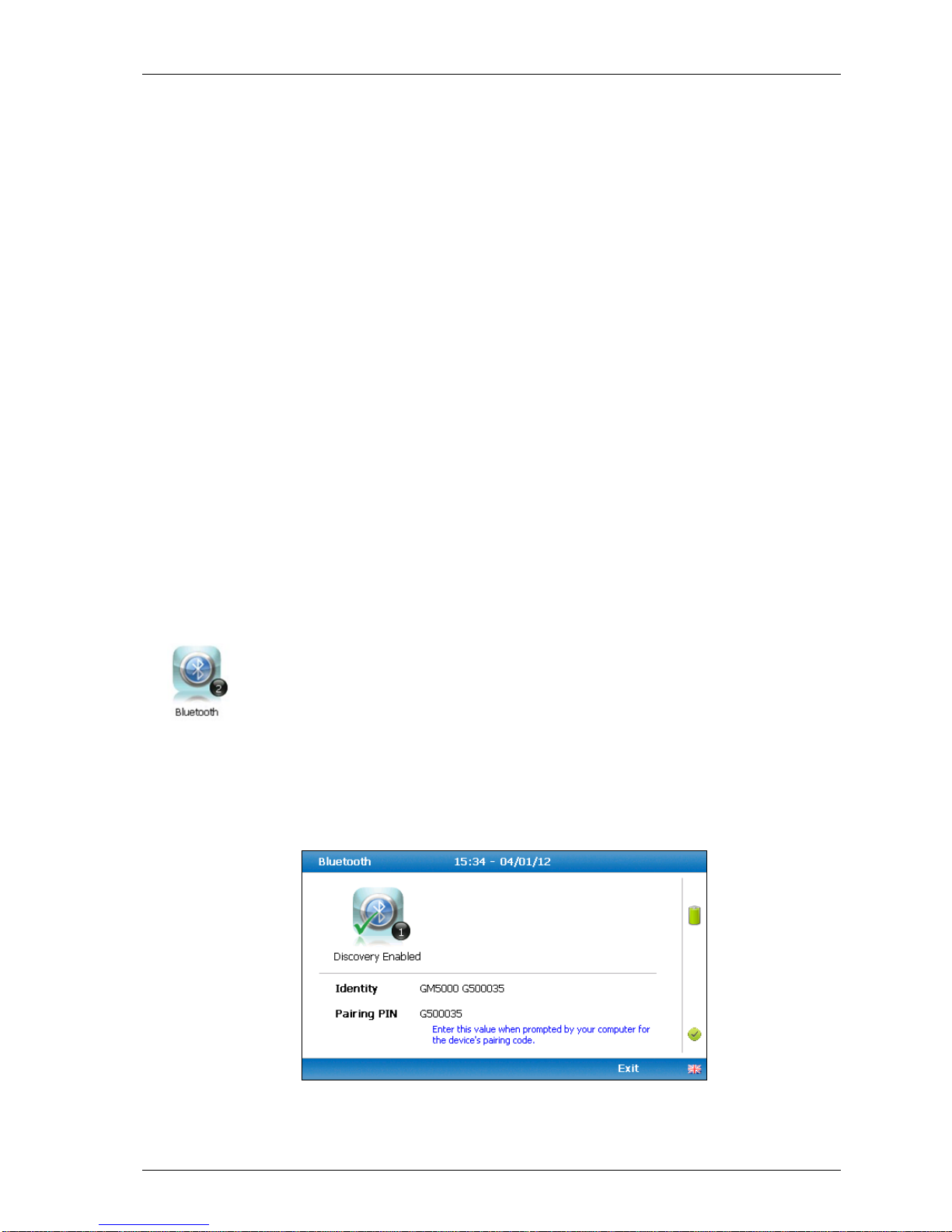
2) Select ‘Key 2 – Bluetooth’ and the following screen is displayed:
Bluetooth options
Page 31
GEM5000 gas analyser OMGEM5KN4
Copyright Geotech Page 31
3) Enter the ‘Pairing PIN’ value when prompted by your computer for the device’s
pairing code.
4) Select soft-key ‘Exit’ to exit the screen and return to the ‘Device Settings’ menu.
7.2.3 Device information
This option displays default instrument information and settings such as
serial number, service due date, last zero calibration date and last span
calibration date.
1) Select the ‘Menu’ key on the front of the analyser to display the ‘Device Settings’
menu.
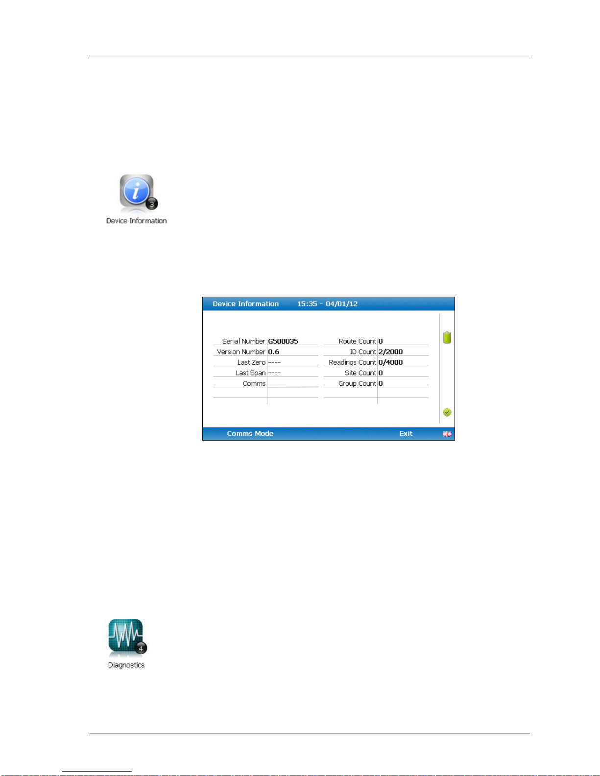
2) Select ‘Key 3 – Device Information’ and the following screen is displayed:
Device information
3) The information displayed on this screen is informational only and cannot be edited
by the operator. The operator may be asked serial number, service due date and
version number information when contacting Geotech.
Note: The comms setting ‘Legacy’ mode is for use with GAM >=v1.5. GA5K
mode is reserved for future applications – DO NOT USE.
4) Select soft-key ‘Exit’ to exit the screen and return to the ‘Device Settings’ menu.
7.2.4 Diagnostics
This option enables the Geotech Technical Support Team to identify and resolve
issues with the instrument and settings. If required, the operator may be
asked to confirm the diagnostics displayed.
1) Select the ‘Menu’ key on the front of the analyser to display the ‘Device Settings’
menu.
Legacy
Page 32
OMGEM5KN4 GEM5000 gas analyser
Page 32 Copyright Geotech
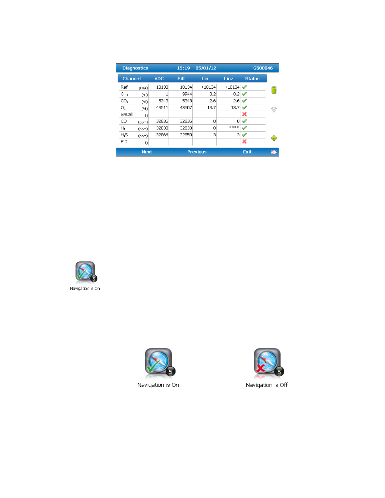
2) Select ‘Key 4 – Diagnostics’ and the following screen is displayed:
Diagnostics
3) Select soft-key ‘Next’ to display the next screen, ‘Previous’ to return to the previous
screen, or select soft-key ‘Exit’ to exit this screen and return to the ‘Device
Settings’ menu.
Note: For further information please contact Technical Support at Geotech on
+44(0)1926 338111 or email [email protected].
7.2.5 Navigation (optional)
This option enables the operator to switch the ‘GPS Navigation’
functionality on or off. (This is optional and dependent upon
purchasing the navigation option).
1) Select the ‘Menu’ key and the ‘Device Settings’ menu is displayed.
2) Select ‘Key 5 – Navigation On’ to switch on the GPS navigation functionality or ‘Key
5 – Navigation Off’ to switch the GPS navigation functionality off.
Note: For further information please refer to section ‘8.0 – Taking Readings’.
Page 33
GEM5000 gas analyser OMGEM5KN4
Copyright Geotech Page 33
7.3 User settings
To access the ‘User settings’ menu, select the ‘Menu’ key on the front of the analyser to
display the ‘Device Settings’ menu followed by the soft-key to display ‘User Settings’
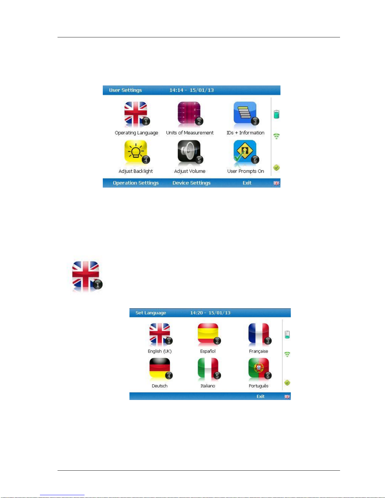
menu. The following menu is displayed:
User settings menu
To exit the user settings menu select the soft-key ‘Exit’.
7.3.1 Operating language
This option enables the operator to specify the operating language
displayed for the instrument.
1) Select ‘Key 1 – Operating Language’ and the following screen is displayed:
Set language
2) Set the required language for the gas analyser by selecting the appropriate function
key. Choose from:
Key 1
English
Page 34
OMGEM5KN4 GEM5000 gas analyser
Page 34 Copyright Geotech
Key 2
Spanish
Key 3
French
Key 4
German
Key 5
Key 6
Italian
Portuguese
3) To exit this option, select the soft-key ‘Exit’ and the operator is returned to the
‘User Settings’ menu.
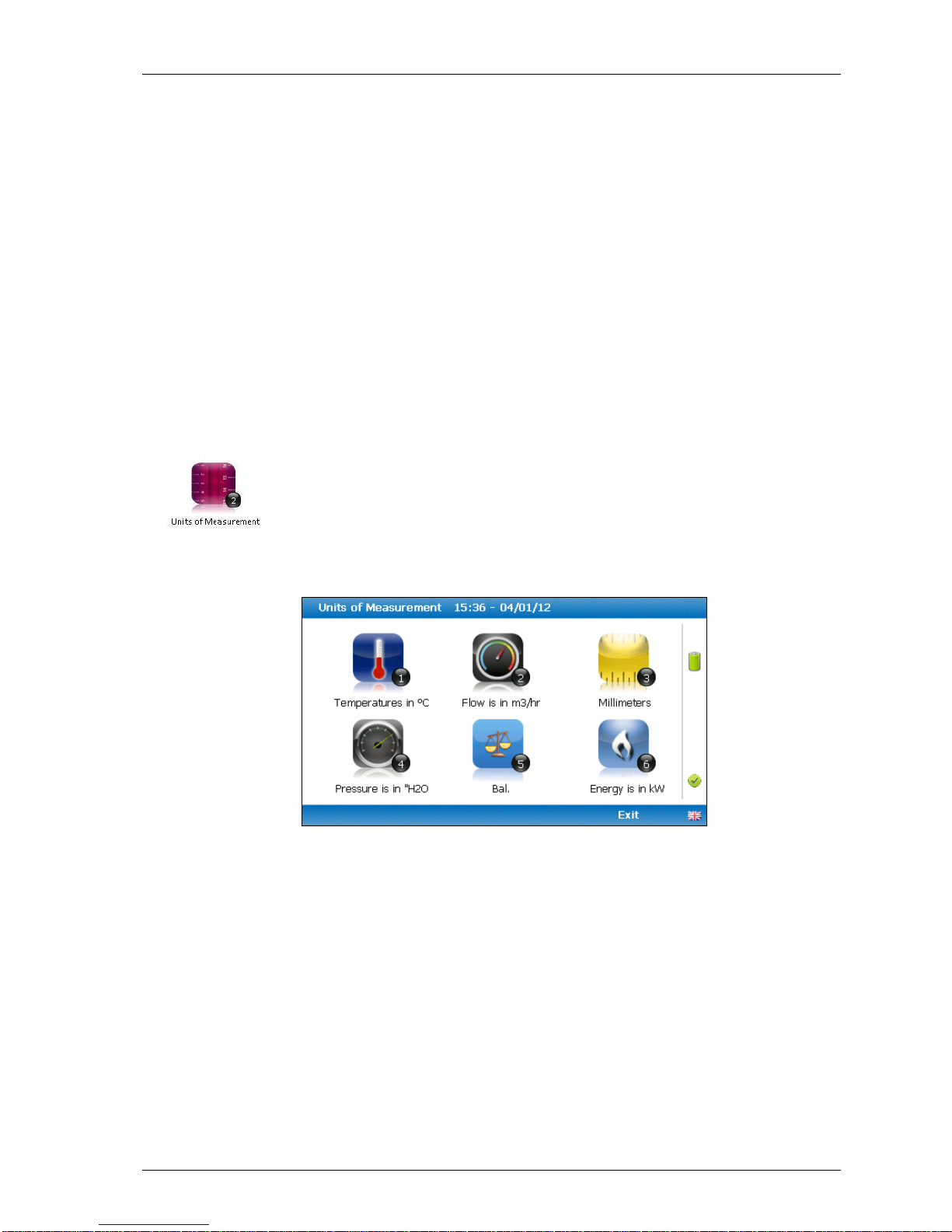
7.3.2 Units of measurement
This option enables the operator to specify the default units of
measurement for the instrument.
1) Select ‘Key 2 – Units of Measurement’ and the following screen is displayed:
Units of measurement menu
2) To set the required units of measurement toggle and choose from the following:
Key 1
Temperature
O
C
OF
Key 2
Flow
scfm
m3/hr
Key 3
Measurement
Inches
Millimetres
Key 4
Pressure
mb
“H2O
Page 35
GEM5000 gas analyser OMGEM5KN4
Copyright Geotech Page 35
Key 5
Balance
Balance
Residual N2
Key 6
Energy
BTU/h
kW
3) Select soft-key ‘Exit’ to exit this screen and return to the ‘User Settings’ menu.
7.3.3 ID selection
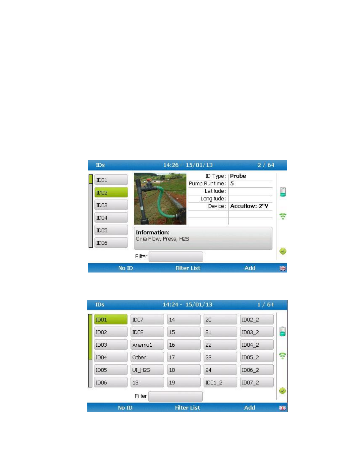
The ID selection screen allows the operator to scroll through all IDs, including those uploaded
from GAM and added directly onto the instrument, and then make a selection. Detailed
information regarding the currently selected ID, such as flow device type and pump runtime,
are displayed below:-
By selecting ‘Key 3’ the operator can toggle between showing 30 IDs and showing 5 IDs with
more detailed information relating to the chosen ID.
Page 36
OMGEM5KN4 GEM5000 gas analyser
Page 36 Copyright Geotech
The technician can scroll between the IDs using the following keys on the instrument keypad:
Two (2) and eight (8) move the selection up/down
Four (4) and six (6) move the selection left/right on the list view
One (1) and three (3) move the selection left/right a page in the list view only
Seven (7) and nine (9) move the selection to first/last ID
Five (5) toggles between the 'ID with information' and 'ID list'
Return/enter key selects the desired ID and proceeds to the navigation or reading
screen.
If there are no IDs present the technician can either add a new ID or press the enter key on
the instrument keypad to return to the previous screen.
Soft keys:
Left - Select 'No ID' and go to the purge/reading screen.
Centre - Enabled when there is a list of IDs, allowing the technician to dynamically
filter the IDs displayed in the list.
Right - Allows the technician to add a new ID to the instrument 'in the field'.
Changing the sort order
By default the IDs are sorted in the order in which they were transferred to the instrument.
To change the sort order between unsorted, sort by name or sorted by distance to travel
press Key 0.
Sorted by original order (not sorted)
Sorted alphabetically
Sorted by distance to travel
Note: Only available when GPS is enabled
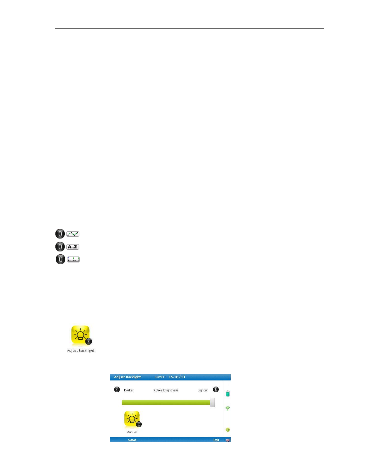
7.3.4 Adjust backlight
This option enables the operator to adjust the backlight (brightness).
Setting this to a darker setting will help preserve the battery power.
1) Select ‘Key 4 – Adjust Backlight’ and the following screen is displayed:
Page 37
GEM5000 gas analyser OMGEM5KN4
Copyright Geotech Page 37
2) Manual adjustment of the instrument backlight is available via this option and can be
carried out with use of ‘Key 4 - Scroll left’ () darker and ‘Key 6 - Scroll right’ (>)
lighter.
3) Select the soft-key ‘Save’ to store the setting or select soft-key ‘Exit’ to exit the screen
without saving the change.
4) The operator will return to the ‘User settings’ menu.
Note: The manually set contrast setting is retained when the read-out is
switched off and may require resetting when next switched on.
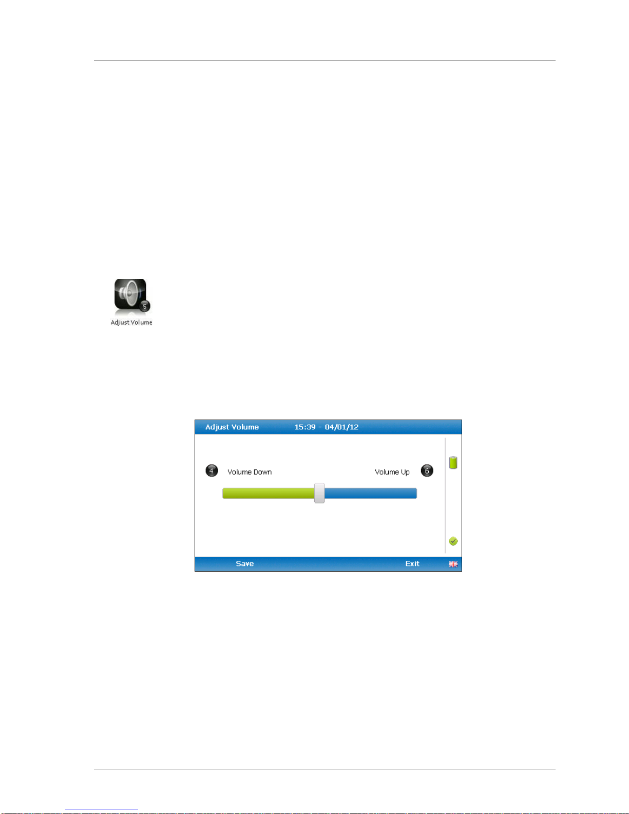
7.3.5 Adjust volume
This option enables the operator to adjust the volume for the internal
speaker, for example the alarm tone. A lower setting will help preserve the
battery power.
1) Select the ‘Menu’ button on the front of the analyser to display the ‘Device Settings’
menu. Press the soft-key to display ‘User Settings’.
2) Select ‘Key 5 – Adjust Volume’ and the following screen is displayed:
Adjust volume
3) Manual adjustment of the volume is available via this option and can be carried out
with use of ‘Key 4 - Scroll left’ () volume down and ‘Key 6 - Scroll right’ (>) volume
up.
4) Select the soft-key ‘Save’ to store the setting or select soft-key ‘Exit’ to exit the screen
without saving the change.
5) The operator will return to the ‘User settings’ menu.
Page 38
OMGEM5KN4 GEM5000 gas analyser
Page 38 Copyright Geotech
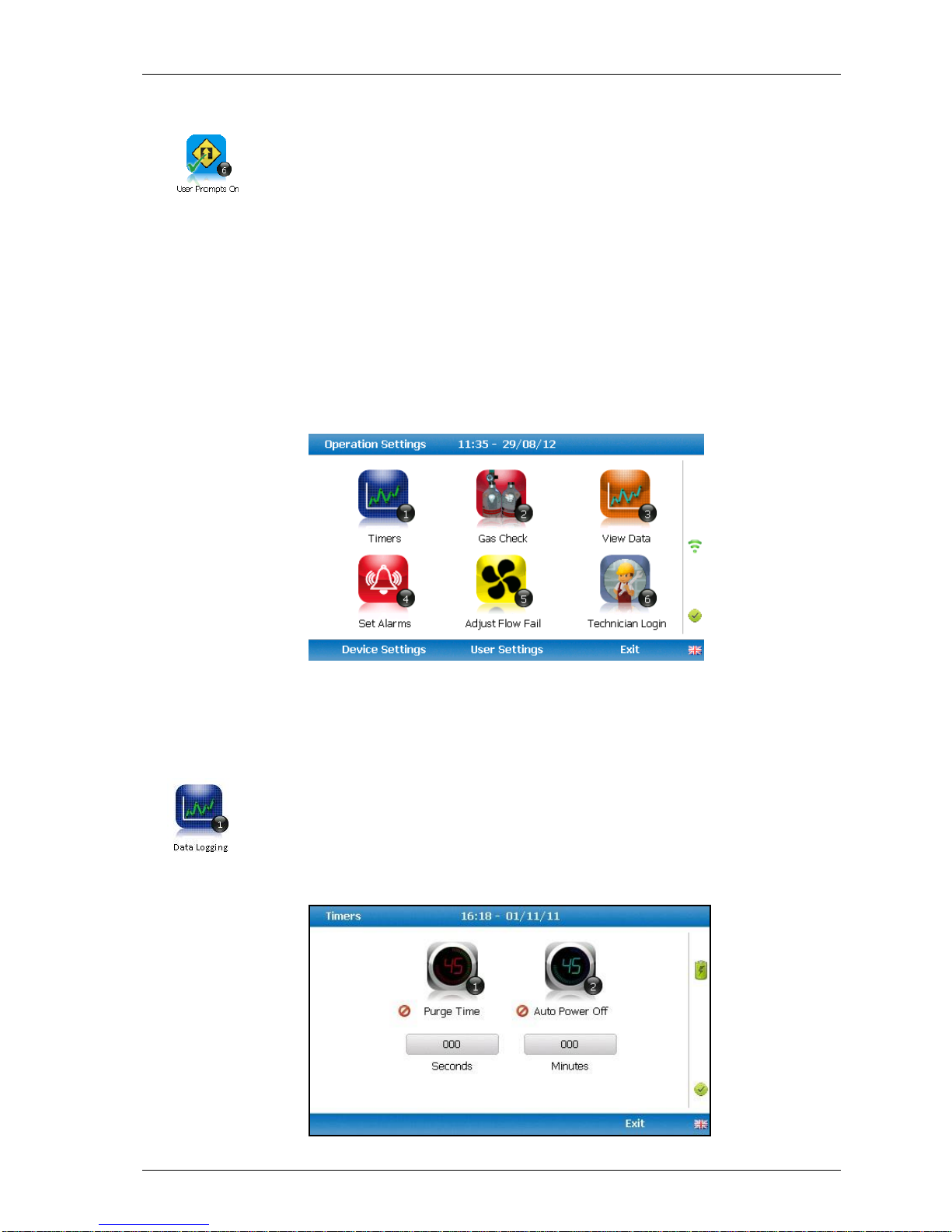
7.3.6 User Prompts
This option enables the operator to either turn on or off the context-sensitive
user prompts which are displayed during the gas sample process. The analyser
will have the user prompts on when it is first used, so if they are no required
they can be switched off by selecting soft-key ‘6’ and this will now be its
default setting. Prompts can be switched back on at any time by returning to this menu
and selecting soft-key ‘6’.
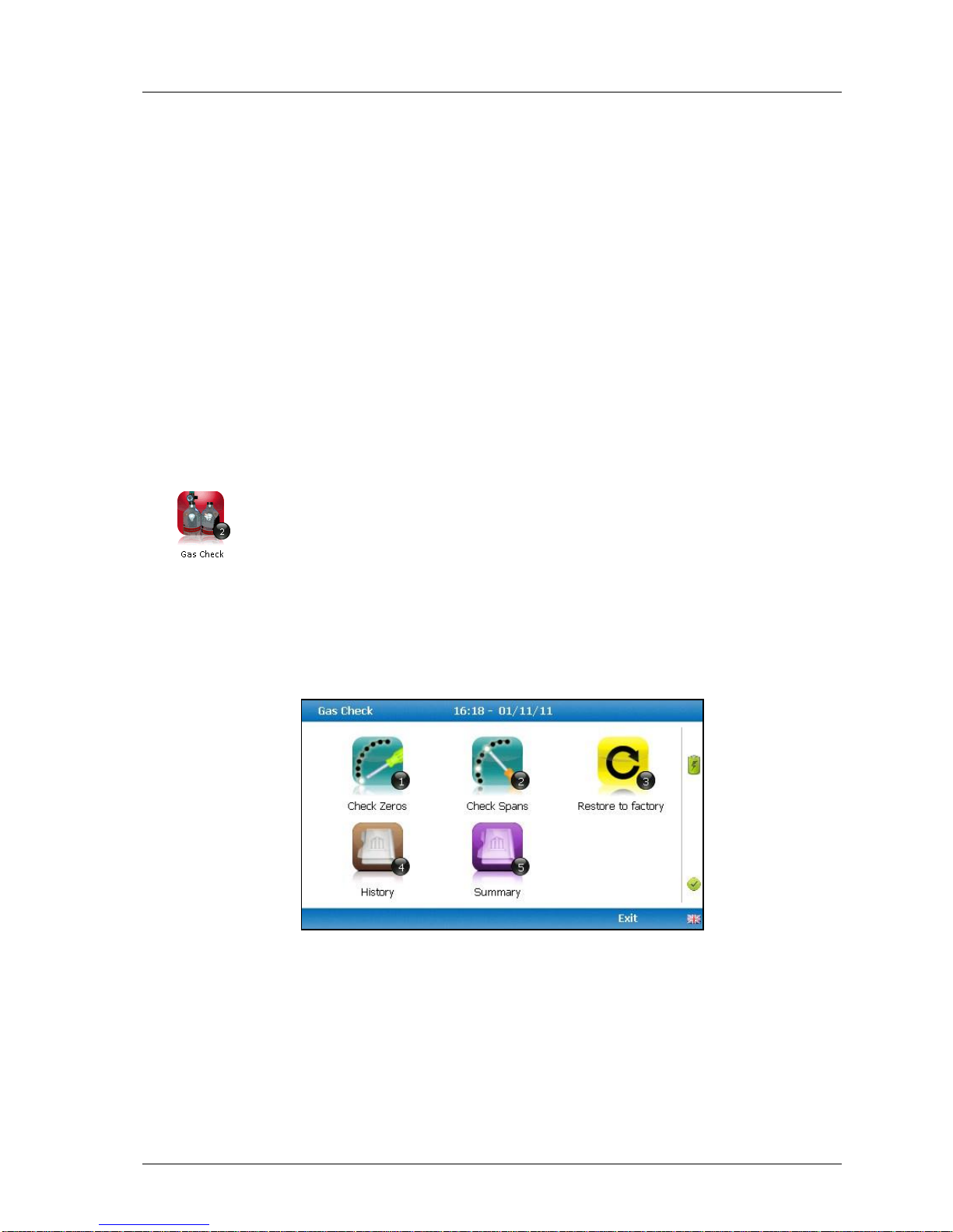
7.4 Operation settings
To access the ‘Operation settings’ menu, select the ‘Menu’ key on the front of the analyser
to display the ‘Device Settings’ menu followed by the soft-key to display the ‘Operation
Settings’ menu. The following menu is displayed:
Operation settings menu
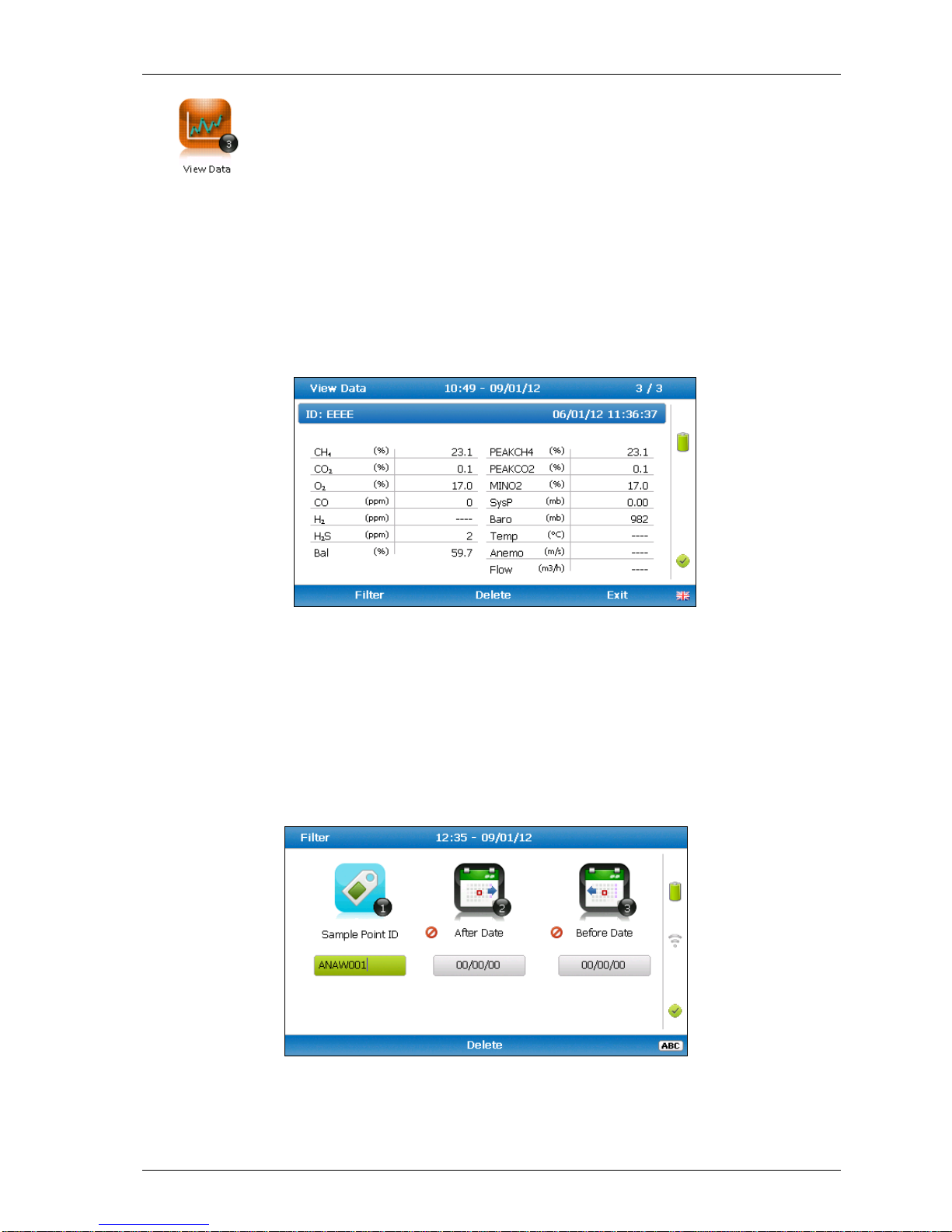
7.4.1 Timers
The timers function enables the operator to set standard purge times and
set auto-power off if the unit is untouched for the period of time specified.
1) Select ‘Key 1 – Timers’ and the following screen is displayed:
Page 39
GEM5000 gas analyser OMGEM5KN4
Copyright Geotech Page 39
1) Select ‘Key 1’ to edit the purge time. Enter the ‘Pump Running Time’ in seconds;
this is the length of time you wish to run the pump to draw the sample, e.g. key in
030 then press the ‘Enter’ key to accept.
2) Select ‘Key 2’ to edit the auto power off time. Enter the ‘Auto power off’ in
minutes; the instrument will automatically power off to preserve the battery life
after the specified time if no activity has occurred on the instrument. Press the
‘Enter’ key to accept.
3) Select the soft-key ‘Exit’ key to exit the screen and return to the ‘Operation
settings’ menu.
Note: Setting the purge time and auto power off functions to zero, disables the
option. It is not recommended to reduce the purge time to below 30
seconds.
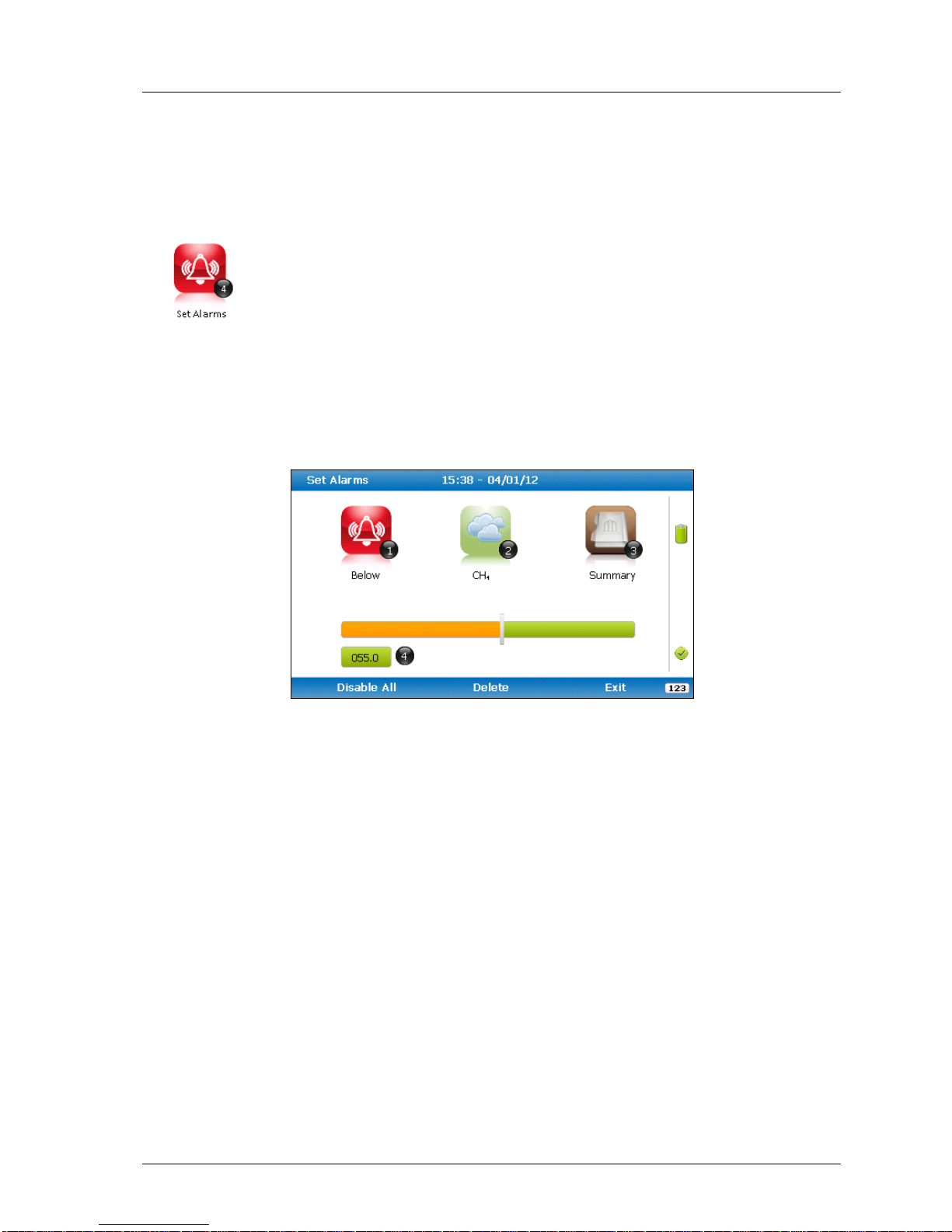
7.4.2 Gas Check
This option displays the ‘Gas Check’ menu and enables the operator to zero
and span the gas channels on the instrument. Historical/previous gas
checks data can also be viewed and factory settings can be restored.
1) Select the ‘Menu’ button on the front of the analyser to display the ‘Device Settings’
menu. Press the soft key to display ‘Operation Settings’.
2) Select ‘Key 2 – Gas Check’ and the following menu is displayed:
Gas Check
3) For more information about the Gas Check Menu please refer to section 9.0 –
Calibration.
4) Select soft-key ‘Exit’ to exit operation settings and return to the main screen.
7.4.3 View data
Page 40
OMGEM5KN4 GEM5000 gas analyser
Page 40 Copyright Geotech
This option enables the operator to view the readings collected and stored
on the instrument. Readings many be downloaded to the optional Gas
Analyser Manager (GAM) software if further analysis is required.
1) Select the ‘Menu’ button on the front of the analyser to display the ‘Device Settings’
menu. Press the soft-key to display ‘Operation Settings’.
2) Select ‘Key 3 – View Data’ and the following screen is displayed:
View data
3) Toggle through the reading by selecting ‘Key 4 – Scroll left’ and ‘Key 6 – Scroll right’
on the analyser. Select ‘Key 2 – Page up’ and ‘Key 8 – Page down’ to page through
the auxiliary channels listed.
4) Select the soft-key ‘Filter’ to filter the data by sample point ID, or specify before or
after date. Press the soft-key ‘Exit’ to exit the filter menu and return to the ‘View
Data’ screen.
Filter data
5) Select the soft-key ‘Delete’ followed by the appropriate soft-key to delete a single
Page 41
GEM5000 gas analyser OMGEM5KN4
Copyright Geotech Page 41
reading or all filtered readings. Press soft-key ‘Cancel’ to cancel the deletion request.
6) Select the soft-key ‘Exit’ to exit the view data screen.
7.4.4 Set alarms
This option enables the operator to define the conditions for which an alarm
will be triggered. These conditions apply to the general operation of the
instrument and are not ID specific. A summary of the alarm settings can be
found in ‘Key 3 – Summary’.
1) Select the ‘Menu’ button on the front of the analyser to display the ‘Device Settings’
menu. Press the soft key to display ‘Operation Settings’.
2) Select ‘Key 4 – Set Alarms’ and the following menu is displayed:
Set alarms
3) Select ‘Key 2’ to select the gas for which you wish to set an alarm trigger followed by
‘Key 1’ to change the trigger condition of an alarm.
4) To manually adjust the alarm set press (<) ‘Key 4 – Scroll left’ or (>) ‘Key 6 – Scroll
right’ and enter the trigger value.
5) To disable all alarm settings select the soft-key ‘Disable All’.
6) Select the ‘Enter’ key’ to store the setting or select soft-key ‘Exit’ to exit the screen
without saving the change.
7) A summary of the alarm settings can be displayed using ‘Key 3 – Summary’. Select
soft-key ‘Exit’ to exit alarms summary and the operator returns to the ‘Operation
Settings’ menu.
7.4.5 Adjust flow fail
Page 42
OMGEM5KN4 GEM5000 gas analyser
Page 42 Copyright Geotech
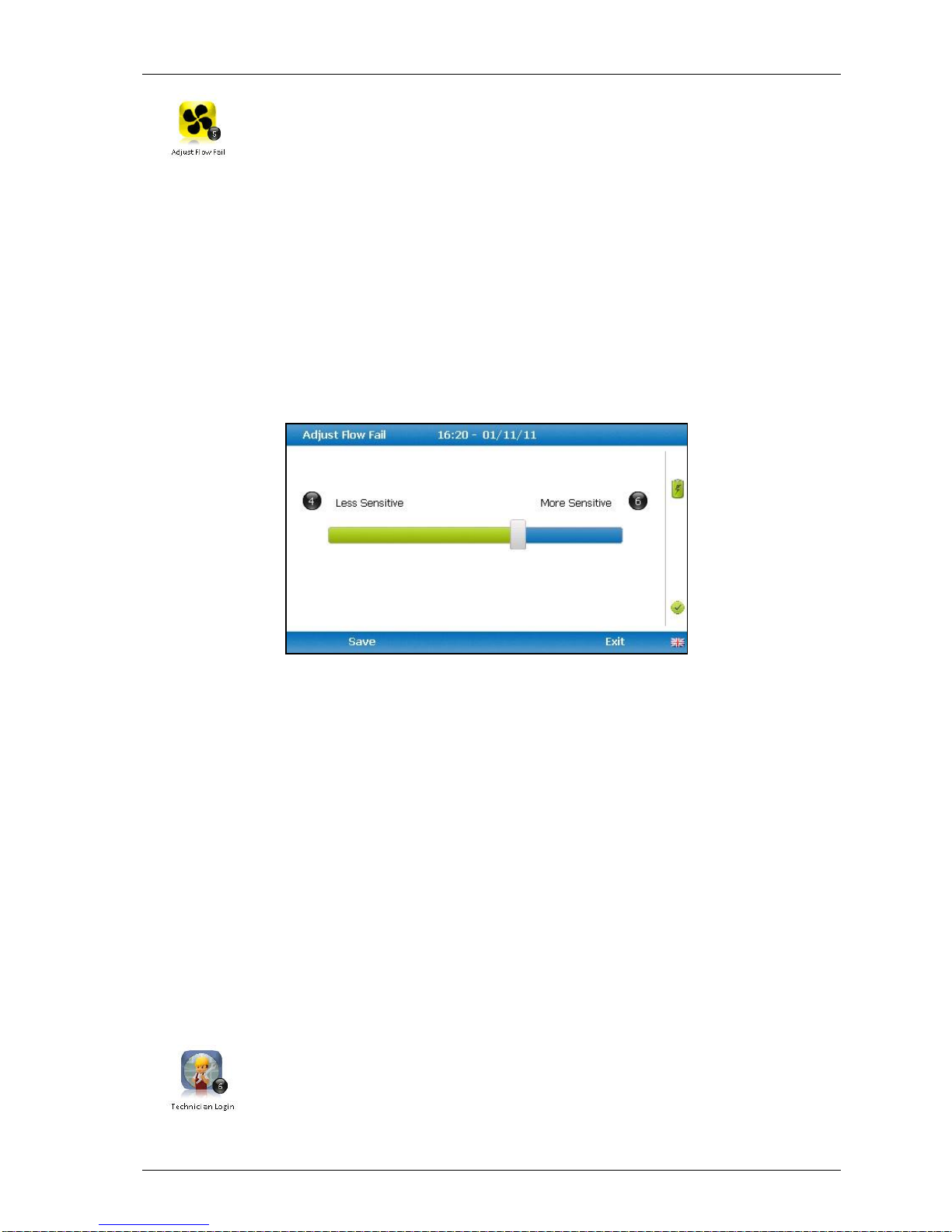
This option enables the operator to adjust the flow fail tolerance of the
instrument, i.e. the operator can adjust the sensitivity for when the pump
will stop operating on the presence of a blockage or low flow.
1) Select the ‘Menu’ button on the front of the analyser to display the ‘Device Settings’
menu. Press the soft-key to display ‘Operation Settings’.
2) Select ‘Key 5 – Adjust Flow Fail’ and the following screen is displayed:
Adjust flow fail
3) Manual adjustment of the flow fail is available via this option and can be carried out
with use of ‘Key 4 – Scroll left’ () less sensitive and ‘Key 6 – Scroll right’ (>) more
sensitive.
4) Select the soft-key ‘Save’ to store the setting or select soft-key ‘Exit’ to exit the screen
without saving the change.
5) The operator will return to the ‘Operation settings’ menu.
Note: The default setting displays the bar in the centre. BEFORE altering this
setting, please contact Technical Support at Geotech on +44(0)1926
338111 or email [email protected]
7.4.6 Technician login
This option enables the operator to select or change a pre-defined
technician login and all subsequent readings will be tagged with this
Technician Login ID. The technician ID must already have been created
using the Gas Analyser Manager (GAM) software and uploaded to the
instrument.
Page 43
GEM5000 gas analyser OMGEM5KN4
Copyright Geotech Page 43
1) Select the ‘Menu’ button on the front of the analyser to display the ‘Device Settings’
menu. Press the soft key to display ‘User Settings’.
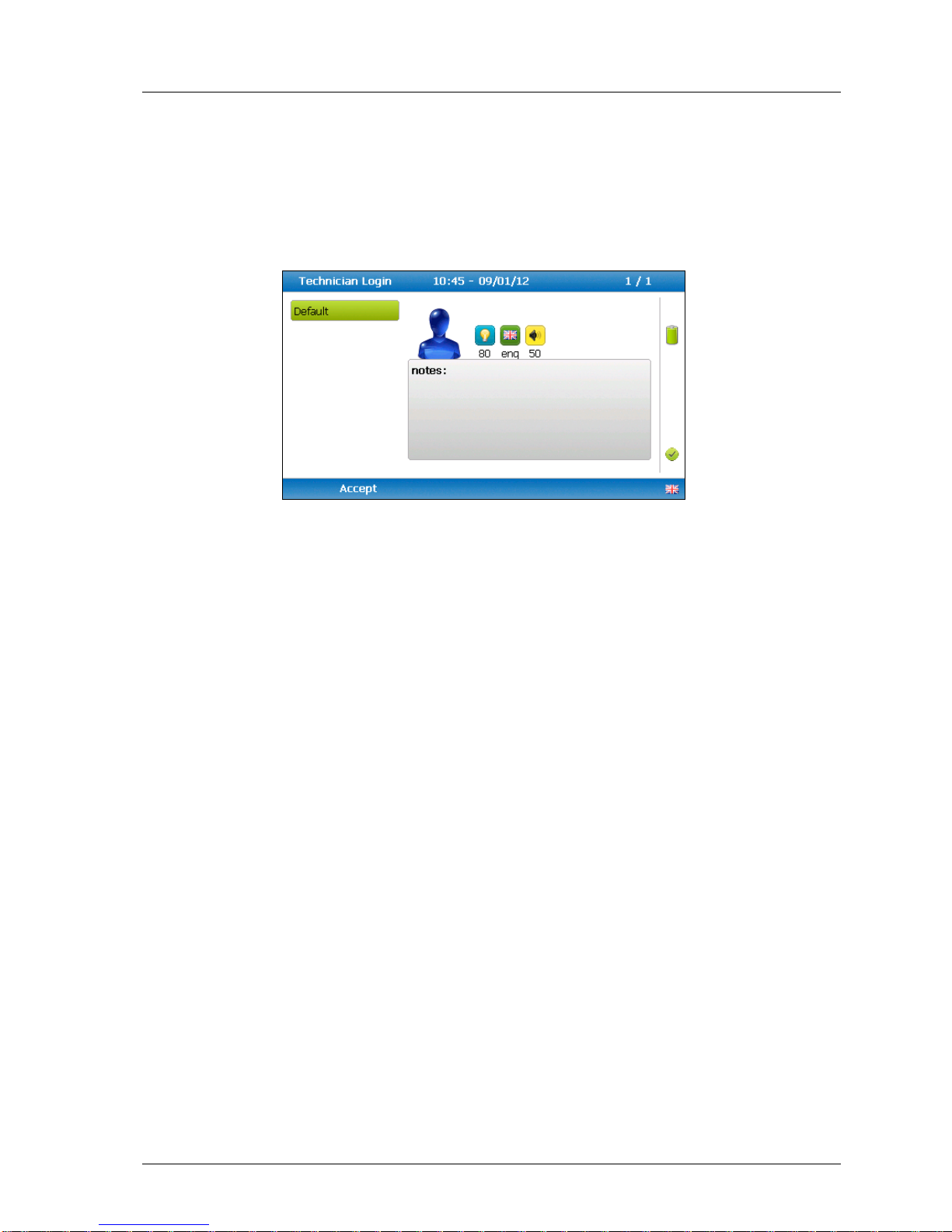
2) Select ‘Key 6 – Technician login’ and the following screen is displayed:
Technician login
3) Use the cursor keys to move throughout the list of IDs displayed; select the ‘Enter’
key to select choice of ID, default if no IDs are listed or soft-key ‘Skip’ to skip the
selection.
4) The operator will return to the ‘User settings’ menu.
Note: If no technicians are loaded via GAM this section is skipped during start
up and the ‘Technician ID’ icon is removed from the menu.
7.5 Exit menu
1) Press the ‘Menu’ button on the front of the analyser to exit settings.
Page 44
OMGEM5KN4 GEM5000 gas analyser
Page 44 Copyright Geotech
8.0 Taking readings
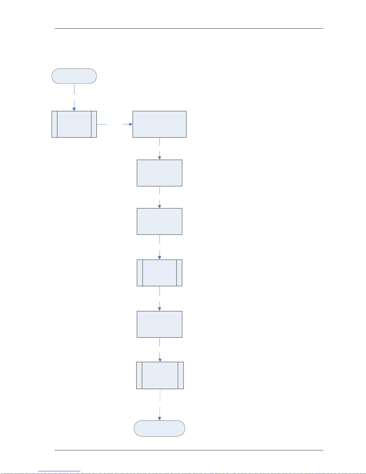
8.1 Preliminary checks before taking readings (best practice)
Prior to use, it is good practice to ensure
that:
Step 1 If using GAM - all necessary ID
codes and information have been
uploaded from GAM to the
analyser.
Step 2 Check the ‘Mode of Operation’ is
correct. Choose either GEM5000
for gas extraction monitoring
analyser or GA5000 for landfill gas
analyser. Change using ‘Special
Actions’.
Step 3 The instrument has the correct
time and date set.
Step 4 The water trap filter is fitted and
is clean and dry.
Step 5 The battery has a good charge
(minimum 25% charge, even if
only a few readings are required).
Step 6 The channels CH4, H2S and CO
have been zeroed, without gas
concentration present.
Step 7 If necessary check the span
calibration with a known
concentration calibration gas.
Step 8 Take readings.
Start
ID codes and
information
uploaded
Battery has
good charge
Check span
calibration
Take readings
Step 1
Step 2
Step 6
Analyser
has correct time
and date set
Check mode of
operation is correct
(GEM /GA)
Water trap filter is
clean and dry
Gases
zeroed
Step 3
Step 4
Step 5
Step 7
Step 8
Page 45
GEM5000 gas analyser OMGEM5KN4
Copyright Geotech Page 45
Warning
Inhaling hydrogen sulphide gas (H2S) or other harmful gases can cause
death. It is the responsibility of the user to ensure that he/she is
adequately trained in the safety aspects of using H2S and other harmful
gases. In particular, where hazardous gases are being used the gas
exhausted from the analyser must be piped to an area where it is safe
to discharge the gas. Hazardous gas can also be expelled from the
instrument when purging with clean air.
Good practice
Travel to site with the gas analyser in the vehicle's interior - not in the boot, where it
may be subjected to extremes of temperature and possible shock damage. Do not
place the gas analyser against anything hot (e.g. gas extraction pipe, car body or in
an unattended car during the summer) as this will cause a temperature increase in
the gas analyser and may cause erroneous readings.
When moving around a site, protect the gas analyser from strong direct sunlight and
heavy rain.
Always use the water trap! If the water trap becomes flooded, change the filter and
ensure all tubes are clear of moisture before re-use.
Note: If the exhaust of a 5000 series gas analyser is connected to a
pressurised system then this results in a flow of gas out of the inlet flow
port.
8.2 Update site data
Prior to taking the readings at a particular site, the site data should be updated. This is
accessed via the ‘Special Action’ menu. The answers to these questions are then stored
and appended to each reading stored thereafter, until the site data is updated for another
site. If using Gas Analyser Manager (GAM) software this data will be uploaded to GAM
along with the reading data.
8.3 Special action
This menu enables the operator to perform the additional following functions out of
sequence if so desired.
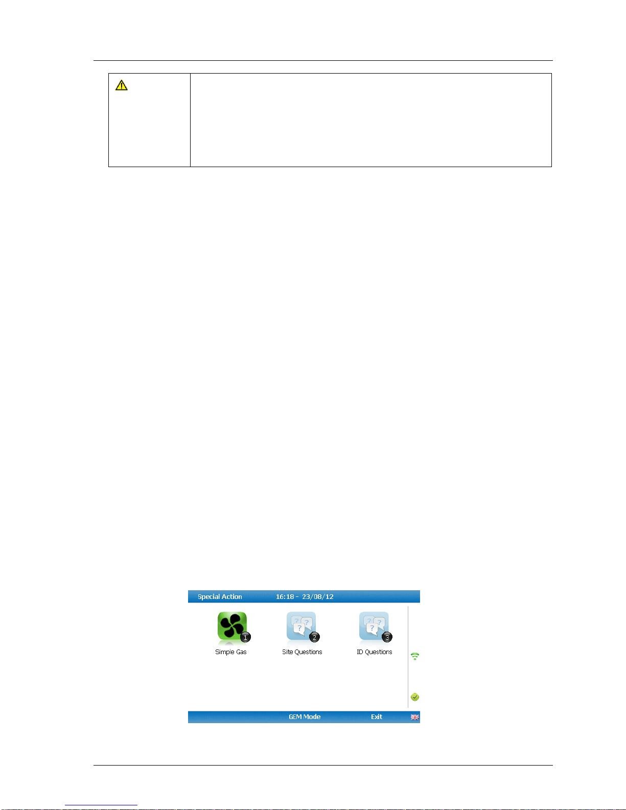
1) From the ‘Main Gas Read Screen’ select the soft-key ‘Special Action’ and the
following menu is displayed:
Special action menu
Page 46
OMGEM5KN4 GEM5000 gas analyser
Page 46 Copyright Geotech
Note: The list of special action options displayed on the special action menu is
dependent upon device type and sequence.
The following actions may be available:
Action
Function
Key 1 – Simple Gas
This action enables the operator to take a quick gas
reading. The pump will start running automatically when
this key is selected. The operator can stop the pump by
pressing the pump key on the keypad at any time and
the reading can then be stored by selecting soft-key
‘Store’.
Key 2 – Site Questions
This action enables the operator to update site questions
prior to taking a reading.
Key 3 – ID Questions
This action enables the operator to update ID questions
specific to sample points prior to taking a reading.
Key 4 – Flow
This action enables the operator to measure internal flow
first when taking a reading. Connect the blue hose to the
sample point. The yellow hose can be vented a safe
distance from the sample point or re-circulated back into
the system. Select either soft-key ‘Zero Flow’,’ Flow
Options’ or ‘Start’ to commence internal flow. Select
soft-key ‘Store’ to store and record the reading.
Key 5 – Enter Temperature
This action enables the operator to manually enter a
temperature reading if not using a temperature probe
prior to taking a gas measurement.
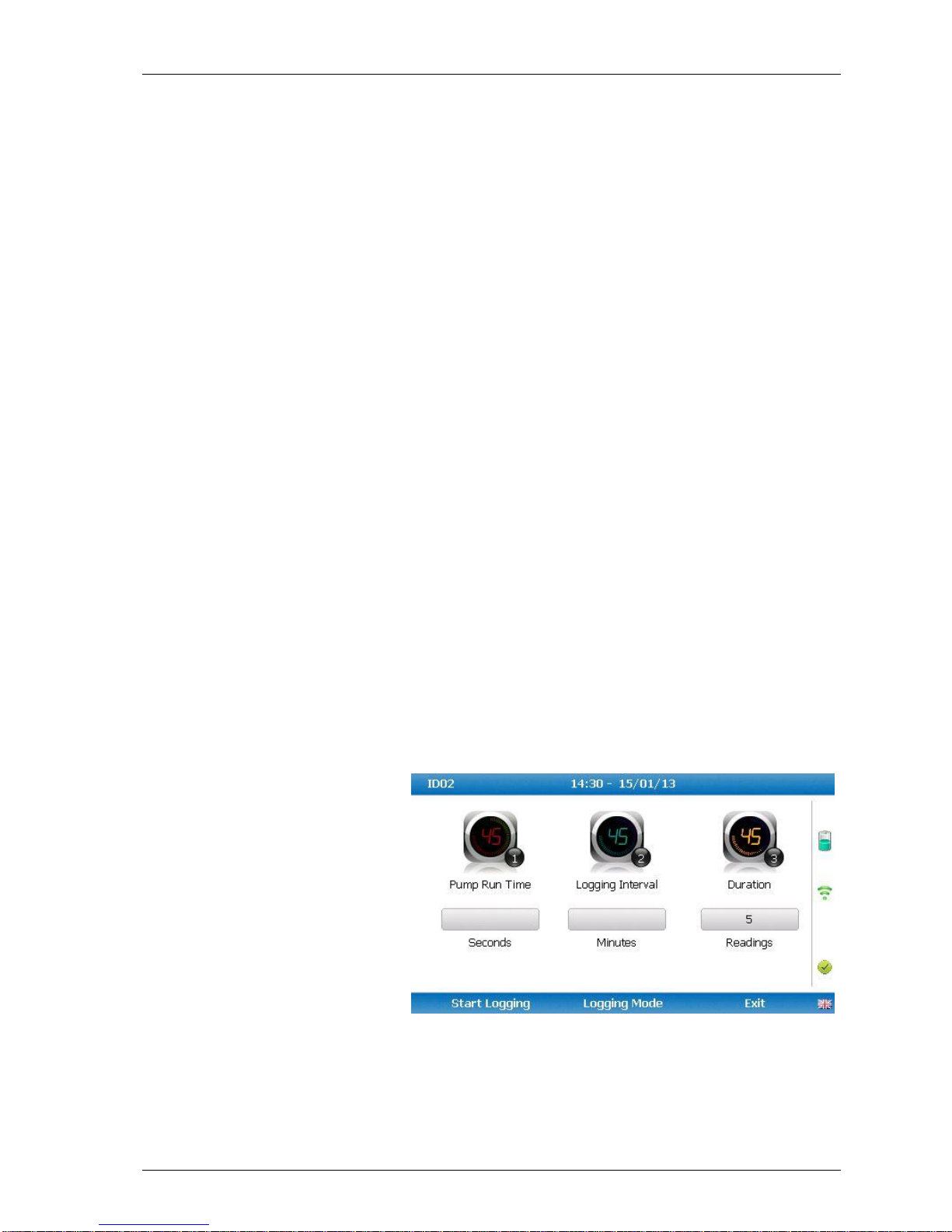
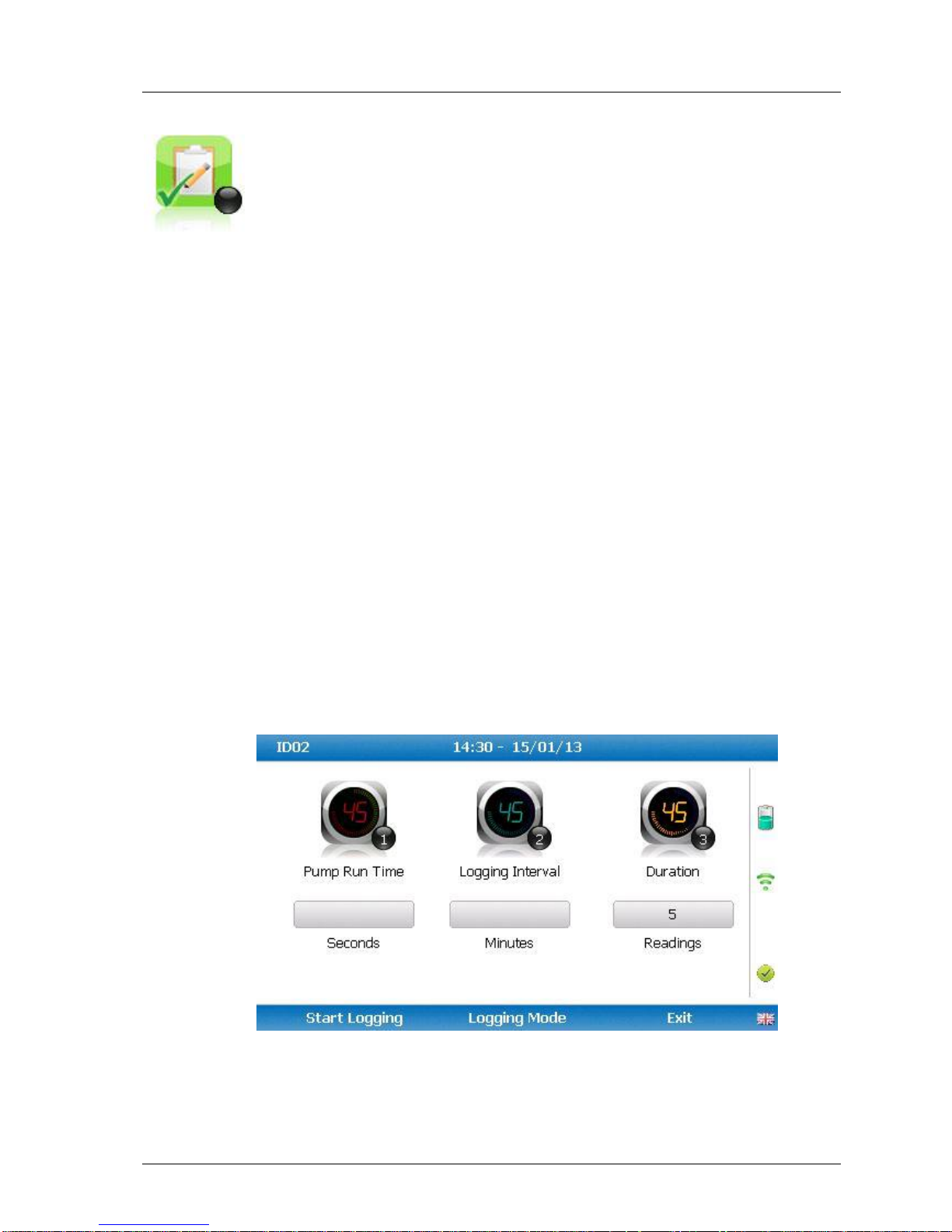
Key 6 – Start Logging
This action enables the operator to leave the analyser
unattended to take samples at a predetermined time.
The reading interval and pump run times may be edited
prior to commencing the logging cycle.
Page 47
GEM5000 gas analyser OMGEM5KN4
Copyright Geotech Page 47
8.3.1 Configuration of the data logging option
1) Connect the blue hose to the sample point. The yellow exhaust hose can be vented a
safe distance from the sample point; do NOT re-circulate back into the system.
2) By selecting ‘Next ID’ the operator can select the ID which is being sampled at
present.
3) Once the ID has been chosen the analyser will commence & complete its clean air
purge cycle.
4) To gain access to the data logging option the operator will be required to select the
’Special Action’ key to obtain the special user options. The data logging option can
then be selected via ‘Key 6’ to configure the logging parameters.
5) Once the operator has confirmed the logging parameters, select soft-key ‘Start
Logging’.
6) Once the logging function has been activated the analyser will carry out a 30 second
warm-up (displayed below the temperature read out at the right of the main gas read
screen) and begin the first sample.
7) If for any reason during the logging cycle the inlet port becomes blocked, the
analyser will sense this as a ‘Flow Fail’ and the pump will automatically retry until the
reading can be obtained. As such care must be taken when positioning the sample
tubing to ensure water/moisture ingress does not occur.
8) Select soft-key ‘Stop Logging’ to stop logging if required.
8.3.2 Profiling option
1) The ‘Logging Mode’ centre soft-key toggles between ‘Logging Mode’ and ‘Profiling
Mode’ and pressing it will change the mode to the one the soft-key describes. For
example, when on the profiling page the key will display as ‘Logging Mode’ and
when on the logging page the key will display as ‘Profiling Mode’.
2) To edit the parameter the operator will be required to select ‘Key 3’ to select the
number of reading required. Once the number of readings has been updated press
Page 48
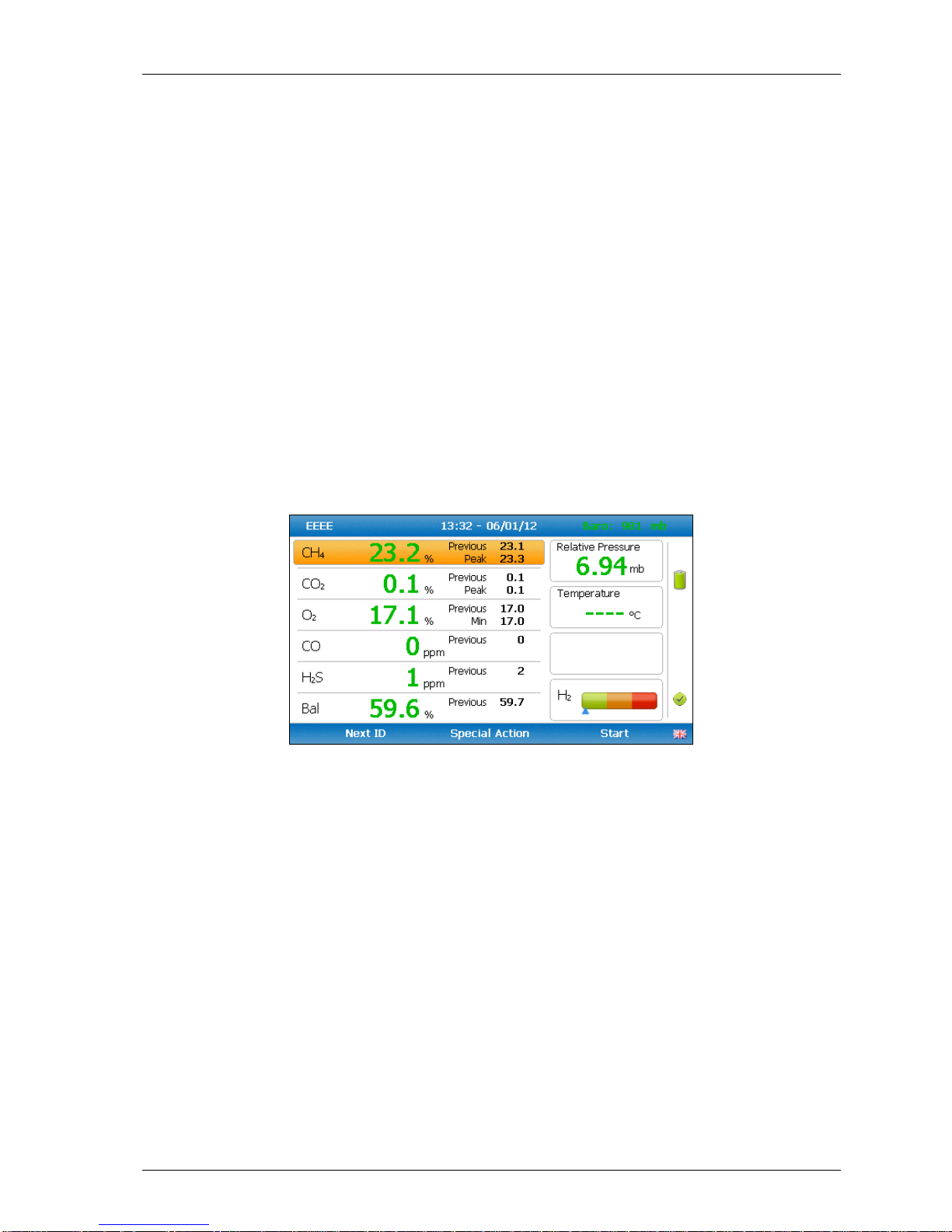
OMGEM5KN4 GEM5000 gas analyser
Page 48 Copyright Geotech
the return key to confirm parameter setting.
3) By selecting ‘Key 2’ the operator can edit the logging interval of their logging
preferences and then confirm the amendments by pressing the return key.
4) Once the logging parameters are confirmed, commence the logging by selecting
the ‘Start Logging’ key.
5) If for any reason during the logging cycle the inlet port becomes blocked, the
analyser will sense this as a ‘Flow Fail’ and the pump will automatically retry until
the reading can be obtained. As such care must be taken when positioning the
sample tubing to ensure water/moisture ingress does not occur.
6) Select soft-key ‘Stop Logging’ to stop logging if required.
Select the soft-key ‘Exit’ to exit this menu and return to the ‘Main Gas Read Screen’.
8.4 GEM analyser in GA mode
The operator may toggle between GEM (a gas extraction monitor) and GA (a landfill gas
analyser) mode of operation if required. From the ‘Special Action’ menu, select the middle
soft-key to toggle between GEM and GA Mode.
GEM analyser in GA mode - main gas read screen
Note: For operating instructions on how to use the GA5000 mode of operation,
please refer to the GA5000 gas analyser operating manual.
8.5 The gas flow measurement screen
The GEM5000 gas analyser enables gas and flow measurements to be recorded by using:
A flow device i.e. a PITOT tube, Orifice plate, Accu-Flo or anemometer.
A temperature probe.
The GEM5000 instrument has the extra functionality to measure the calculated calorific
value of the gas. The site engineer uses the information recorded by the analyser to make
adjustments to the gas flow for specific boreholes. The initial and adjusted flow rates are
recorded.
Page 49
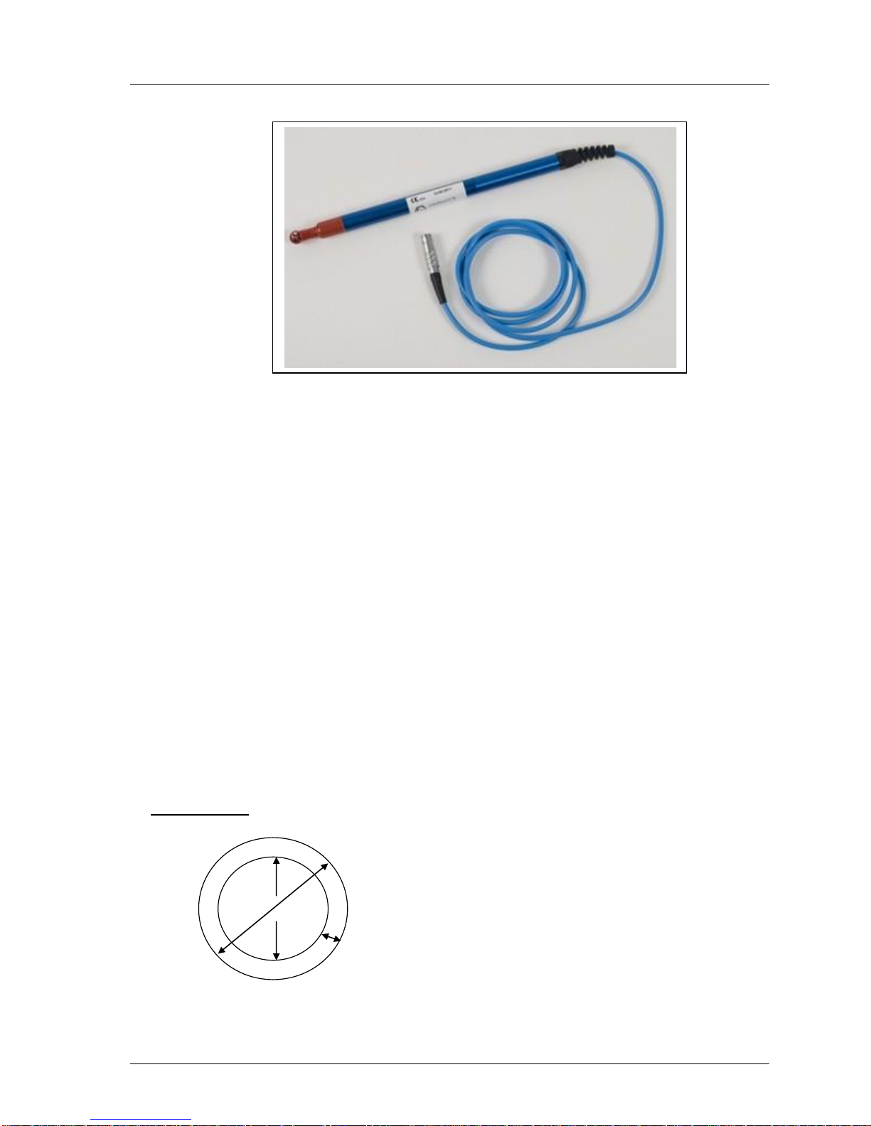
GEM5000 gas analyser OMGEM5KN4
Copyright Geotech Page 49
8.6 How to use an anemometer (optional)
The GEM5000 gas analyser has the facility to attach an anemometer device enabling the
site engineer to measure the flow of gas within an extraction system. The anemometer
can be set to display two values; m/s (meters per second) and m3/hr (metres cubed per
hour).
It is best practice to take the gas reading first before taking the flow reading with the
anemometer attached.
If using a ‘borehole ID’ the internal pipe diameter can be predetermined in the optional
Gas Analyser Manager (GAM) software. Once set, the site engineer cannot edit the pipe
diameter setting.
If the site engineer is not using a borehole ID or the pipe diameter is not set in GAM the
operator will be prompted to enter a pipe diameter with a new ID on the analyser. Select
soft-key ‘Next ID’ from the Main Gas Read screen, followed by soft-key ‘Add’ and add a
new borehole location.
In order to use the anemometer it is important to know the internal diameter (ID) of the
pipe if you want to calculate the flow in m3/hr (metres cubed per hour). This must be the
internal diameter not the outer diameter (OD) i.e. pipe outer diameter minus twice the
pipe wall thickness.
For example:
If you do not have any suitable monitoring points you will need to drill (tap of ¾” BSP pipe
thread) a hole in the piping of between 25mm and 30mm in diameter to seat the conical
Pipe ID
Pipe OD
Wall Thickness
Page 50
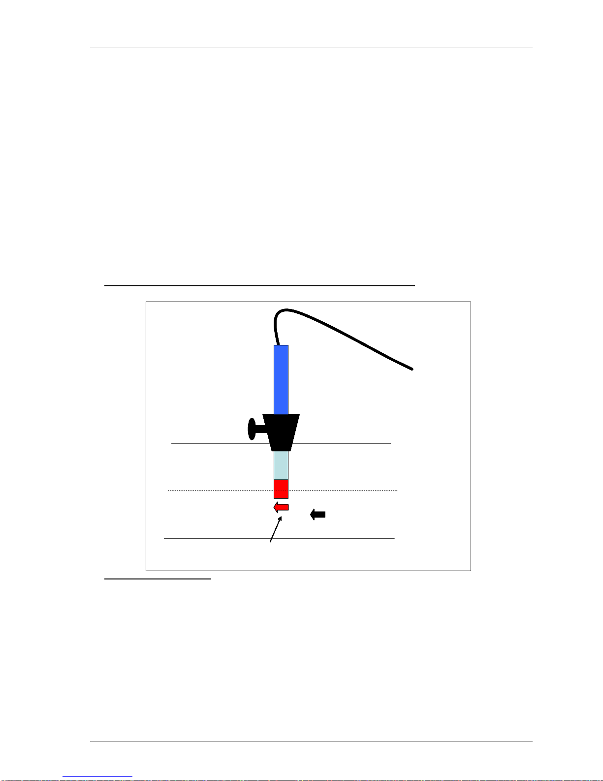
OMGEM5KN4 GEM5000 gas analyser
Page 50 Copyright Geotech
fitting on the anemometer (which is roughly between 20mm to 34mm). When not in use
the hole can be re-sealed with a ¾” BSP male bung.
Note: When the anemometer is not in use the conical fitting should be placed over
the probe to protect it.
The anemometer must fit centrally (the conical fitting must be set on the probe to half the
pipe ID before insertion). The arrow on the tip of the probe must point in the direction of
the gas flow.
Note: Use the thumb screw to help align the direction of the probe into the gas
stream.
Flow readings are most accurate when there is laminar flow (not turbulent). Turbulence
can be caused by a change in pipe direction or restriction. Ideally, upstream you want at
least 20 times the pipe ID along the length of the pipe without restriction or bend.
Downstream, you want at least five times the pipe ID along the length of the pipe i.e. for a
100mm ID you need 2000mm of clear pipe upstream, 500mm downstream.
Example to show anemometer fitting into the sample point:
Instructions for use:
1) Attach the anemometer to ‘Connector C’ (refer to section 5.3 – Instrument
connection points).
2) Place the anemometer into the pipe (sample point) ready to take the reading.
3) To take a flow measurement when using an anemometer, follow the instructions
displayed on the analyser. When the reading has stabilised press the ‘Enter’ key to
store the reading.
Conical Fitting
Pipe Centre Line
Pipe
Head
Flow Direction
Thumb Screw
Anemometer
Conical Fitting
Pipe Centre Line
Pipe
Head
Direction of the arrow must be in the same direction as the flow
Flow Direction
Thumb Screw
Anemometer
Conical Fitting
Pipe Centre Line
Pipe
Head
Flow Direction
Thumb Screw
Anemometer
Conical Fitting
Pipe Centre Line
Pipe
Head
Direction of the arrow must be in the same direction as the flow
Flow Direction
Thumb Screw
Anemometer
Page 51

GEM5000 gas analyser OMGEM5KN4
Copyright Geotech Page 51
Anemometer cleaning instructions:
General handling tips:
Protect the probes against severe vibration.
Do not kink the connector cable (risk of cable breakage).
Never allow hard objects to contact rotating impellers.
Always carry out probe cleaning according to the cleaning instructions.
Never immerse probes in solvent.
Never blow probes through with compressed air.
Allow hot probes to cool slowly, never cool by plunging them in cold water etc.
Cleaning instructions:
Instrument and probe must be switched off or disconnected prior to cleaning.
Vane probes:
As the probes are highly sensitive measuring instruments, they must be cleaned with
great care.
Fibres or other foreign bodies can be carefully removed with fine tweezers. When
doing so, take care not to bend or otherwise damage the vanes or the spindle.
The adjustment of the bearing screws must never be changed. This can result in an
erroneous measurement.
Never allow hard objects to contact rotating impellers.
Cleaning agents that extract the plasticizer from the plastic are never to be used for
plastic probes (practically all solvents).
Cleaning the probes – best practice:
Note: Use soapy water.
Cleaning example:
1) Carefully, swish the top part of the impeller back and forth in clean soapy water for
approximately 10 minutes. Then swish the top part of the impeller back and forth in
clean soapy water. If soapy water is used as a cleaning agent it is advisable to wash
out the soap solution thoroughly with distilled water.
2) After cleaning the probe, rub it dry with a clean, dry cloth.
Page 52
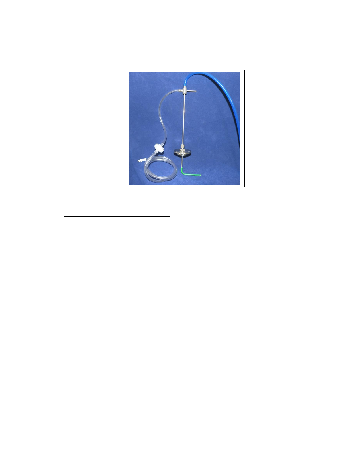
OMGEM5KN4 GEM5000 gas analyser
Page 52 Copyright Geotech
8.7 How to use a pitot tube (optional)
The GEM5000 gas analyser enables the site engineer to take gas measurements using a
pitot tube. The pitot tube is used for gas extraction systems and the pressure readings
are taken in mbar. Gas flow is calculated in the analyser in m3/hr (metres cubed per
hour).
Example of a pitot tube
Fitting a pitot tube to the analyser:
1) It is important to seat the pitot tube into the monitoring point with the tip facing into
the gas flow. The pitot tube should also be housed half way down the monitoring
pipe. (Please refer to the anemometer instructions, which detail how to calculate the
pipe diameter correctly).
2) Make sure that the sample tubing attached to the pitot tube fits correctly.
3) Attach the sample tube from the top connection of the pitot tube to the ‘blue port’
(the differential port) on the analyser making sure that the gas port connector secure
into place.
4) Attach the sample tube from the side of the pitot tube to the ‘white port’ (inlet
port/static pressure port) on the analyser making sure that the gas port connector
secures into place.
5) House the pitot gland correctly onto the monitoring point.
6) When taking a gas reading and flow measurement follow the instruction as displayed
on the front of the instrument.
Note: Please refer to the following section for a diagram showing how to fit the
tubing to the pitot tube.
Page 53

GEM5000 gas analyser OMGEM5KN4
Copyright Geotech Page 53
8.8 How to use an H2S filter (optional)
8.8.1 Cross gas effects on chemical cells
Measurements of CO are important in landfill management. The GEM5000 analyser
incorporates an improved CO measurement.
Measurements of CO can be affected by two other gases that can be found in landfill gas
– hydrogen and hydrogen sulphide.
To reduce the effect of hydrogen, the GEM5000 analyser uses a technique that is
hydrogen compensated. Hydrogen compensation is achievable up to a level of around
2000ppm. Above this level the CO reading will not be compensated for.
In order to assist the operator the GEM5000 instrument also indicates the level of
hydrogen present as low, medium or high. If a high hydrogen reading is present then the
CO reading may be affected.
The effect of hydrogen sulphide is eliminated by the use of a H2S filter.
CO measurement
The CO measurement is sensitive to hydrogen sulphide. The presence of hydrogen
sulphide can cause the CO reading to elevate (not to be the true value due to the
interfering gas). If the presence of hydrogen sulphide is suspected to be causing false CO
readings, then it is recommended that the external hydrogen sulphide filter is used whilst
obtaining the CO measurement.
The H2S filter only needs to be used when you are trying to remove of any possible cross
gas effects H2S might have on other gas channels. Do not use the filter on all boreholes.
When using the H2S filter you will need to increase the gas sample and clean air purge
run-time, as using an H2S filter decreases the response time of the analyser.
Note: There is an internal H
2
S filter incorporated in the chemical cell that removes
the H2S; however this has a limited life span.
The electrochemical cells used to measure H2S and CO do suffer from cross-gas effects.
Such effects are not accurately specified. However, the following table may be useful as
a guide; it represents how many ppm would be read by a cell if 100 ppm of the
interfering gas were applied, with no other cross-contaminates being present in the
sample.
GEM5000
Interfering Gas
CO
H2S
SO2
NO2
H2
Chemical
Cell
CO
(H2 compensated
100
0 / ~300*
0 0 <1
CO
100
<4 /~300*
0
-20 to +5
<60
H2S
<4
100
20
<-25
<0.2
*after internal filter depleted.
Note: Other gases could cause cross-gas effects. If you suspect a cross sensitivity
problem please contact the Technical Support Team at Geotech on
+44(0)1926 338111.
Page 54
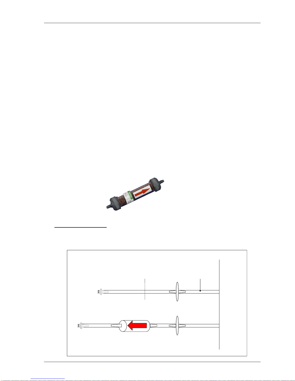
OMGEM5KN4 GEM5000 gas analyser
Page 54 Copyright Geotech
8.8.2 Cross-gas effects on methane, carbon dioxide and oxygen
Methane is measured using dual beam infrared absorption. Analysers are calibrated using
certified methane mixtures and will give correct readings provided there are no other
hydrocarbon gases present within the sample (e.g. ethane, propane, butane, etc). If
there are other hydrocarbons present, the methane reading will be elevated (never
lower) than the actual methane concentration being monitored.
The extent to which the methane reading is affected depends upon the concentration of
the methane in the sample and the concentration of the other hydrocarbons. The effect
is totally non-linear and difficult to predict.
Note: The effect can be reduced by using an H
2
S filter as it can reduce higher
order hydrocarbons. When using the H2S filter you will need to increase the
gas sample and clean air purge run-time, as using an H2S filter increases the
response time of the analyser.
Carbon dioxide is measured by infrared absorption at a wavelength specific to carbon
dioxide. Therefore, the carbon dioxide reading will not be affected by any other gases
usually found on landfill sites.
The oxygen sensor is a galvanic cell type and suffers virtually no influence from CO2, CO,
H2S, NO2, SO2 or H2, unlike many other types of oxygen cell.
The infrared sensors will not be ‘poisoned’ by other hydrocarbons and will revert to
normal operation as soon as the gas sample has been ‘purged’.
H2S filter:
Instructions for use:
The following diagram shows how to modify the standard water trap and sample tubing
to fit the H2S filter.
Sample
Point
Sample
Tubing
Cut the
Sample
Tubing
Water
Trap
Insert
H2S
Filter
Gas Port
Connector
Standard Water Trap and Sample Tubing
Modified Water Trap and Sample Tubing with H2S Filter
Page 55
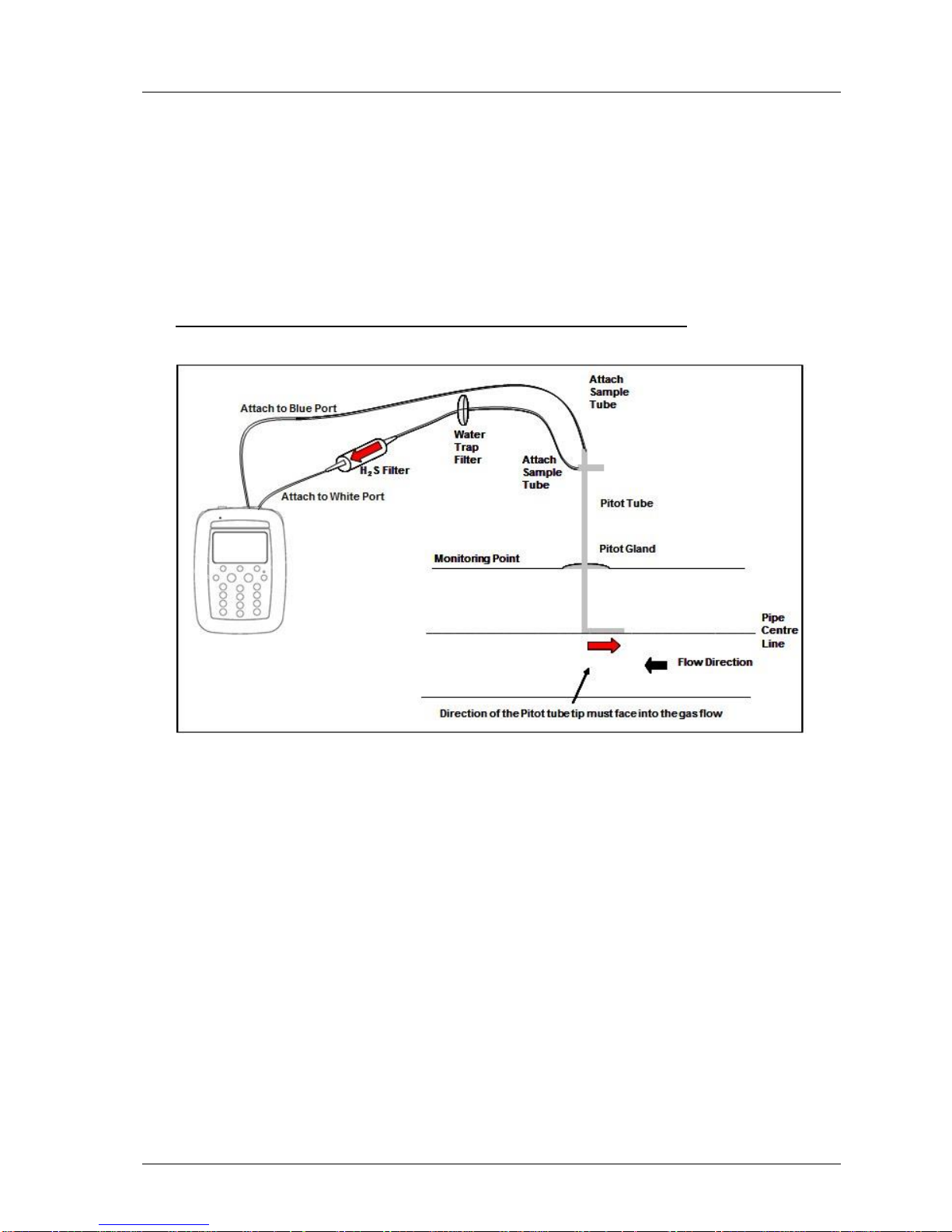
GEM5000 gas analyser OMGEM5KN4
Copyright Geotech Page 55
Note: When onsite the site engineer must have an unmodified water trap assembly
in addition to the modified water trap with a H2S filter in order to take
readings with and without a filter.
1) Once the H2S filter is fitted follow the instructions as detailed on the front of the gas
analyser displayed when taking readings using a H2S filter.
Note: This is only for analysers fitted with the CO compensated cell.
Fitting a pitot tube to a sample point when using an H2S filter:
2) Make sure the water trap filter is fitted as close as possible to the pitot tube. This
will help protect and trap moisture before it reaches the H2S filter. Make sure that
the water trap filter is clean and dry.
3) Attach the sample tubing into the analyser.
4) To take flow readings using a pitot tube, please follow the instructions displayed on
the front of the instrument. The user will be prompted to complete each step and
should follow the instructions on screen.
Note: It is important to fit the pitot tube central and parallel with the pipe.
Page 56
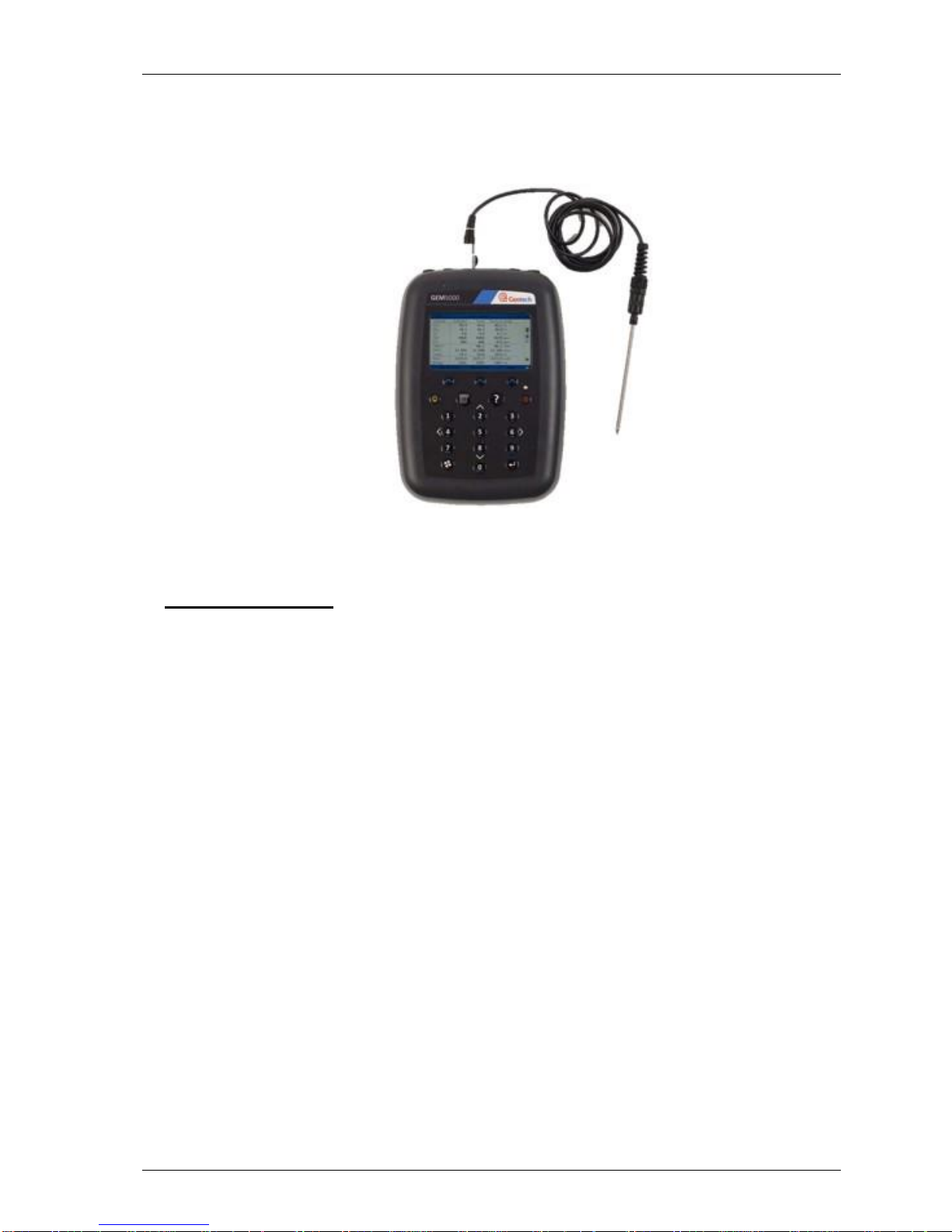
OMGEM5KN4 GEM5000 gas analyser
Page 56 Copyright Geotech
8.9 How to use a temperature probe (optional)
The temperature probe enables the site engineer to measure the temperature of the gas
within a sample point. The GEM5000 gas analyser uses the temperature of the gas to give
more accurate flow measurement readings as part of the instrument calculation.
GEM5000 & temperature probe
Instructions for use:
1) The temperature probe reading is taken along with the gas measurement reading.
2) The analyser must be at the ‘Main Gas Read Screen’.
3) Attach the temperature probe to ‘connector B’ (refer to section 5.3 – Instrument
connections points).
4) Insert the temperature probe into the sample point (borehole) at the same time as
you attach the sample tube to the sample point (two sample points are required for
the borehole).
5) Follow the instructions on the front of the instrument when taking your gas and
measurement reading.
6) At the point in which the operator presses ‘Enter’ to store the gas reading the
temperature is recorded.
Note: Temperature probe readings can be analysed further when downloaded
to Gas Analyser Manager (GAM).
8.10 How to identify a borehole using the GPS feature (optional)
An optional GPS feature is available for the GEM5000 gas analyser. It enables the site
engineer to automatically locate borehole IDs using GPS satellite signal from predefined
borehole IDs uploaded from Gas Analyser Manager. The GPS reading data is stored for
each measurement reading.
Page 57
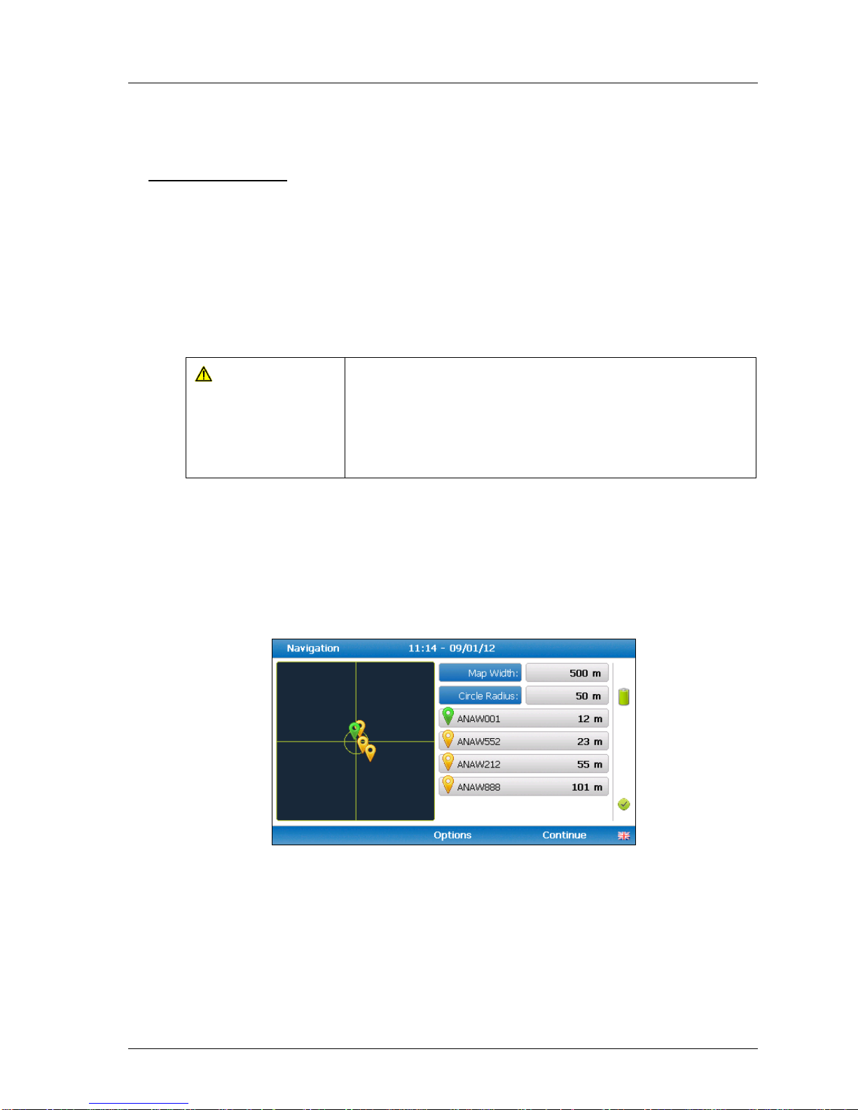
GEM5000 gas analyser OMGEM5KN4
Copyright Geotech Page 57
Note: Borehole IDs may be uploaded from GAM with or without location
information. If location details are not uploaded the location longitude and
latitude coordinates can be stored when the borehole is located and
downloaded to GAM with the reading measurements.
Screen navigation:
1) Switch on the analyser and wait for the self-test warm-up to complete and the
analyser will display the ‘Main Gas Read Screen’.
2) In order to use the navigation function if configured, you must switch ‘Navigation -
On’ on the analyser. Select the ‘Menu’ key followed by ‘Key 5’ to toggle navigation to
on. Select the ‘Menu’ key to exit and return to the ‘Main Gas Read Screen’.
3) Select the soft-key ‘Next ID’, then select a borehole ID from the list displayed and
press the ‘Enter ‘key to continue.
Warning
Before entering the GPS Navigation Screen for the first
time the following health and safety message will be
displayed.
“Please be aware of the terrain when using this screen.
You are responsible for your own safety whilst walking onsite!”
4) After reading the user warning message, select the soft-key ‘Dismiss’. Use the
tracking display to locate the borehole
Note: There is often a wait time frame of between 30 seconds to two minutes
whilst getting a satellite signal. Be aware that heavy rain, trees
overhead etc. will give a bad fix.
5) Once the operator selects a borehole ID the ‘GPS Navigation’ screen is displayed.
Navigation
6) If required select soft-key ‘Options’ to go to the ‘Navigation Options’ menu and the
following screen is displayed:
Page 58
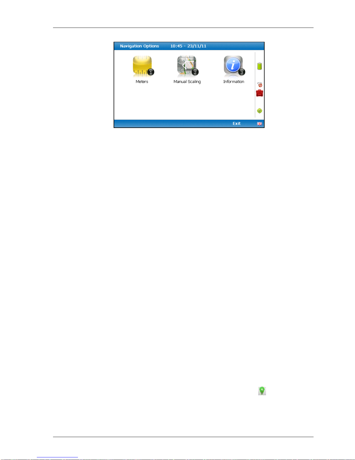
OMGEM5KN4 GEM5000 gas analyser
Page 58 Copyright Geotech
Navigation options
Key 1
Key 1 to toggle between ‘Meters’, ‘Feet’ or ‘Yards’ to
define the unit of measurement.
Key 2
Key 2 to toggle between ‘Manual Scaling’ and ‘Automatic
Scaling’ to locate a sample point using a satellite signal.
Key 3
Key 3 to display sample point information:
Bearing:
Direction.
UTC time:
‘Universal Time Code’ received from the satellite and
displays GMT.
Latitude:
Latitude displays as degrees, minutes, seconds and
decimal seconds. The equator is 0.
Longitude:
E (East) or W (West) displays the longitude as degrees,
minutes, seconds and decimal seconds. The Greenwich
meridian defines the zero point.
Altitude:
Altitude displays in meters, feet or yards.
Satellite:
This is the number of satellites that the system can
select. Four satellites will give reasonable position
accuracy; eight or more satellites will increase accuracy.
Horizontal:
Estimate of horizontal error on the indicated position.
The location is accurate to horizontal error 1.6m.
Vertical:
Estimate of vertical error on the indicated position.
HDOP:
‘Horizontal Dilution of Precision’ which measures the
accuracy of the indicated position.
Changing the selected ID
It is possible to change the currently selected ID (identified by green icon ) by pressing the
2 and 8 and keys to move the cursor up and down the list of visible Ids. To change the
selection press Enter. Notice that the selected ID moves to the top of the list and its icon
turns green.
Page 59

GEM5000 gas analyser OMGEM5KN4
Copyright Geotech Page 59
Changing the scale
You can change the display’s scale by using the 4 and 6 keys to zoom in and out.
GPS signal strength:
This icon shows the signal strength the analyser’s GPS module is able
to provide. Full, okay and fair strength respectively.
GPS failure - the GPS was unable to get a line of sight lock on enough
satellites. Or, it may be that it hasn’t had time to get a lock.
7) Select soft-key ‘Continue’ and the operator is returned to the ‘Main Gas Read Screen’.
Page 60
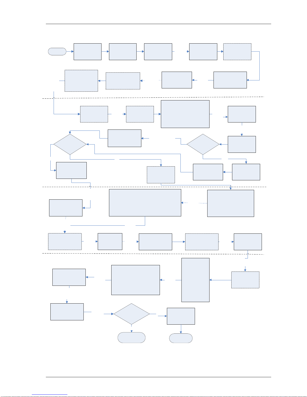
OMGEM5KN4 GEM5000 gas analyser
Page 60 Copyright Geotech
8.11 Taking gas and flow measurement
START
END
If using GAM
Set up GAM &
UPLOAD to
analyser
Air Purge
Instrument screen
Disconnect all tubing
and allow analyser to
purge with fresh air.
Select soft-key ‘Next’
If using GAM
Download
readings to GAM
Select
soft-key
‘Next’
GO TO select or
add borehole ID
YES
Zero Transducers
screen
Select Technician
ID if required or
soft-key ‘Skip’
Select
soft-key
‘Next ID’
Main Gas Read
Screen
Instrument
warm up
Disconnect all tubing from the
sample points and wait for
readings to stabilise. Select
soft-key ‘Next’ to continue
if readings return to zero,
otherwise to remove an offset
perform a zero
Connect the clear tubing to the static pressure
sample point. The blue tubing should be
connected to the differential pressure sample
point. The yellow exhaust tube must be vented to
atmosphere, a safe distance from the user.
DO NOT re-circulate back into the system.
Select
soft-key
‘Next’
Are you
using a
temperature
probe?
Wait for
Pump
to run
(i)
Attach
temperature
probe
Insert temperature
probe into the
sample point
Measure initial gas
flow reading displayed
in the Main Gas Read
Screen
Attach temperature
probe or key in
temperature manually
and press ‘Enter’
Adjusted Flow
Readings Fixed
NO Select soft-key
‘Temperature’
Take another
reading?
NO
Select
soft-key
‘Next’
Select or Add
Borehole Id and
press the ‘Enter’
key
If configured -
operator may locate
sample point using
GPS
Wait then
select
soft-key
‘Continue’
If required select soft-
key ‘Special Action’ to
update site & ID
question (ii)
Select
soft-key
‘Exit’
Main Gas Read
Screen
Gas Measurement
screen
Select
soft-key
‘Start’
Connect the clear sample tube to
the sample point. The yellow
exhaust tube should be vented a
safe distance from the user or
re-circulated back into the
system.
Wait for the initial
readings to
stabilise
Select
soft-key ‘Next’
Initial Gas
Readings Fixed
Select
soft-key
‘Next’
Select
soft-key
‘Next’
Wait for adjusted
readings to stabilise
on the Main Gas
Read Screen
System Pressure
Screen (iii)
Disconnect all
tubing from the
sample points and
wait for readings
to stabilise. Select
soft-key ‘Next’
if readings return
to zero, otherwise
to remove an
offset perform a
zero
Connect the clear sample tube to
the sample point. The yellow
exhaust hose should be vented a
safe distance from the sample
point or re-circulated back into
the system.
Pressure Readings
Fixed
Select
soft-key
‘Next’
Readings stored
successfully
Select
soft-key
‘Store’
Select
soft-key
‘Dismiss’
Wait for initial
readings to stabilise
on the Main Gas Read
Screen
Initial Flow
Readings Fixed
KEY:
(i) If GPS configured the first reading
will display a warning message. Select
soft-key ‘Dismiss’ to continue.
(ii) Special action – if required change
the analyser into GA mode of
operation.
(iii) System pressure reading only
available if set up on GAM.
NOTE: To restart a reading select soft-
key ‘Special Action’ followed by key 1
‘Restart Process’.
Are you
using an
anemometer?
Attach anemometer
& insert into the
sample point
YES
YES
NO
Select soft-key
‘System Pressure’
Select
Soft-key
‘Next’
Select
soft-key
‘Next’
Select
Soft-key
‘Next’
Taking a system pressure reading
Taking a flow reading
Taking a gas measurement reading
Select
soft-key
‘Next’
Input the temperature
on the Main Gas
Read Screen and
press the ‘Enter’ key
Page 61

GEM5000 gas analyser OMGEM5KN4
Copyright Geotech Page 61
9.0 Calibration
9.1 Calibration introduction
The GEM5000 gas analyser is carefully calibrated at manufacture and when returned for
service. However, it is sometimes desirable to be able to carry out a calibration process
between services.
This section outlines the correct procedures to enable the site engineer to field calibrate
the gas analyser.
Note: This does not replace the factory service and calibration. If this calibration is
completed incorrectly it may decrease the accuracy of the gas analyser.
CH
4, CO2
and O2 can be measured by GEM5000 gas analyser as standard; these channels
can be user calibrated. The analysers have other gas channel options that are specified at
manufacture; these too can be calibrated. This section will describe in detail how to
calibrate the three standard gas channels plus the CO channel.
The GEM5000 instrument can have a H2 compensated CO channel. This option requires
that H2 is used in the calibration process and is also set out within this section.
For the other gas channel options contact Geotech for advice.
Two important terms that are used within this section are ‘Zero’ and ‘Span’.
Zero: The point at which the gas analyser is calibrated when there is none of the target
gases present.
Span: The point at which the gas analyser is calibrated when a known quantity of the
target gas is present.
9.2 Frequency of calibration – best practice
The GEM5000 gas analysers can be checked against a known concentration of gas, to give
confidence that the analyser is operating as expected at the time and conditions in which it
is being used.
It is recommended that the instrument is regularly serviced and calibrated by Geotech in
accordance with the due date on the instrument.
When defining the frequency of user calibration, the following are factors to be considered:
The frequency of use of the analyser. (daily?/monthly?)
The level of confidence and accuracy required for readings to be taken.
Historical user calibration data.
Site specific requirements or conditions.
Historical understanding of expected readings on site.
Zeroing of the gas analyser should be undertaken at the start of each day’s monitoring.
Use historical data to drive your frequency of calibration.
If there is no historical data a good starting point for a daily monitoring round is
performing a calibration once every week or every other week.
The results of the calibrations will need to be recorded to monitor over time whether the
frequency of calibration needs to be increased or decreased relative to the confidence
required.
Page 62
OMGEM5KN4 GEM5000 gas analyser
Page 62 Copyright Geotech
The confidence required will be driven by the site specific / user requirements.
When undertaking the monitoring with an understanding of the history of the gas levels of
that site, a calibration check could be triggered if the readings measured are different to
what is expected.
Note: For assistance please contact Technical Support at Geotech on +44(0)1926
338111
9.3 Calibration gases
User calibration of a gas analyser will greatly improve the data accuracy in the range of
the calibration gases used. This may cause less accurate readings of concentrations
outside this calibrated range. Users should select the correct calibration gas for the
expected gas levels on their particular application.
To improve calibration at lower levels requires the use of gas mixtures 1 and 2.
To improve higher levels use gas mixture 3.
For standard CO only 100ppm CO gas is needed.
For CO (H2 compensated) both CO 100ppm and H2 1000ppm gases are needed.
The following table indicates the different gas mixture canisters used for calibration:
Calibration gas
CH4
CO2
O2
Mixture 1
5%
5%
6%
Mixture 2
5%
10%
0%
Mixture 3
60%
40%
0%
Calibration targets for gas cells are dependent on the gas/range and type of cell fitted.
Contact Technical Support for assistance.
These are for general use but other gas concentrations can be used.
Note: The above gases and most other gas concentrations can be supplied by
Geotech. For further information please contact Sales on +44(0)1926 338111
or email [email protected].
Warning
Calibration gases can be dangerous.
For each gas used the appropriate material safety data sheet
must be read and understood before proceeding.
Page 63
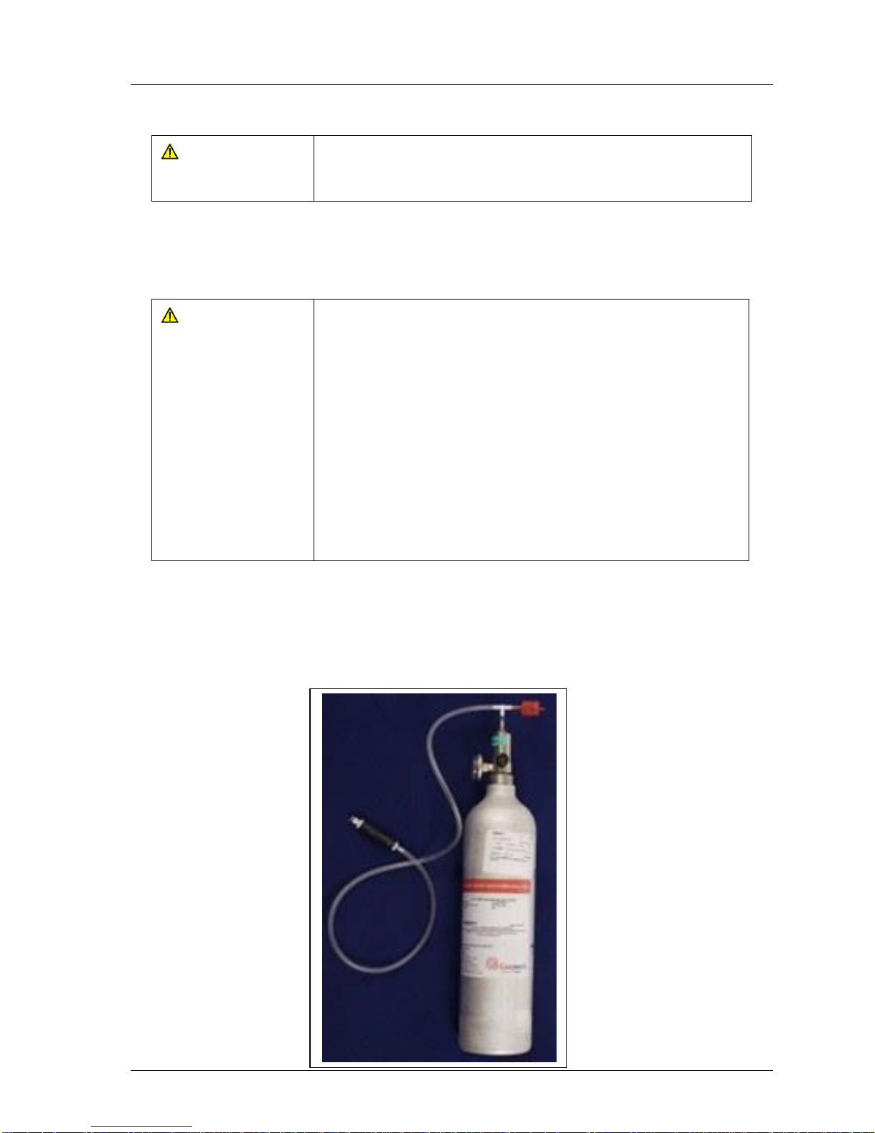
GEM5000 gas analyser OMGEM5KN4
Copyright Geotech Page 63
9.4 Calibration set-up
Warning
Do NOT attach the gas supply to the gas analyser before
putting the analyser into the ‘Gas Check’ screen. Select
‘Check Spans’ from the ‘Operation Settings’ menu.
The regulator supplied with the calibration kit has been configured to deliver a fixed flow.
As the regulator’s flow is factory set, it only requires a few turns to open, no adjustment is
necessary.
Warning
Exhaust port
When the gas analyser is being calibrated, there are two
possible exits for the gas, via the usual manner out of the
exhaust (yellow) port of the analyser or in cases of overpressurisation the 1/16” port on the red pressure relief valve
located on the regulator.
It is recommended that both ports have exhaust tubing
attached.
The exhaust tubing must emerge in a well-ventilated area.
Ensure there are no leaks in the tubing and connections.
The calibration of the gas analyser should be carried out in a
safe area with all necessary precautions taken when using
potentially dangerous, explosive or toxic gases.
Note: There is also potential for gas to expel from the internal flow (blue) port of the
gas analyser (applies to the GA5000 only).
9.5 Calibration equipment
The diagram below displays the regulator and tubing equipment for user calibration:
Page 64
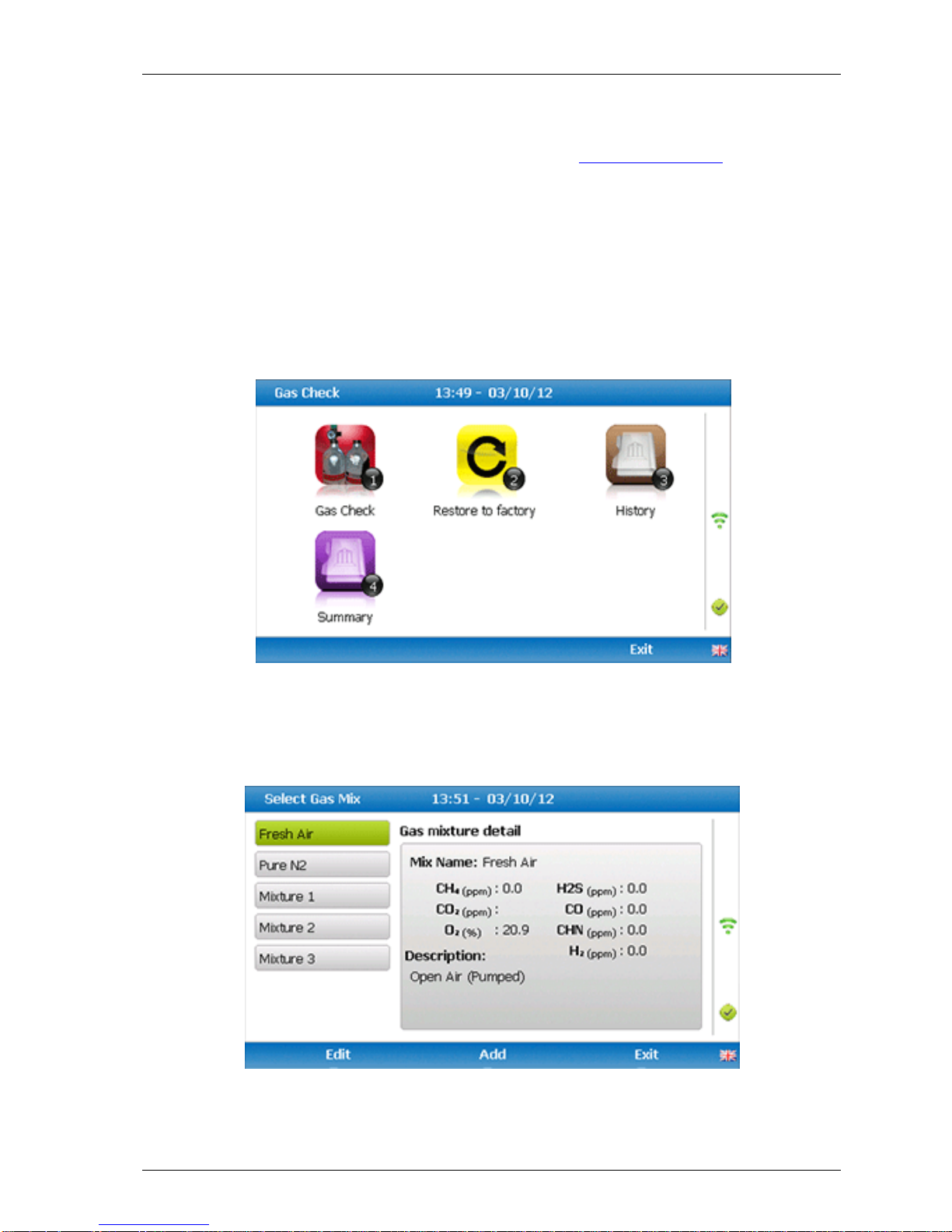
OMGEM5KN4 GEM5000 gas analyser
Page 64 Copyright Geotech
Certified calibration gas in 110 litre gas canisters are supplied with the Geotech
calibration kit. Please refer to the Geotech website www.geotech.co.uk for further
information.
The regulator supplied with the calibration kit is pre-set for flow and pressure rates
that are factory set.
9.6 Gas analyser
For the GEM5000 gas analyser the calibration options can be found by selecting the ‘Menu’
key followed by soft-key ‘Operation Settings’. Select ‘Key 2 – Gas Check’ then follow the
instructions on the analyser screen by selecting ‘Key 2 – Gas Check’.
9.7 Calibration processes – best practice
The following process diagrams outline the calibration steps.
Page 65
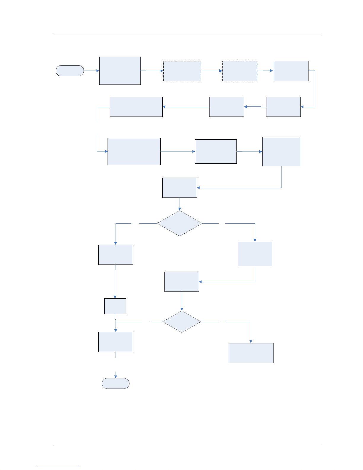
GEM5000 gas analyser OMGEM5KN4
Copyright Geotech Page 65
9.7.1 Gas Check in fresh air
START
Switch on the
instrument and
complete the
instrument warm up.
Main Gas Read
Screen select the
‘Menu’ key
Select key 2
‘Gas Check’
Select key 1
‘Check ’
Wait for the readings to
stabilise. Wait for the
analyser to zero for
approx. 1 min.
Message will display
‘Please wait for timer
to reach zero’
When complete a
message will
display ‘Check
complete please
confirm results’
READ STATUS
FIELD
Select soft-key
‘Calibrate’
READ STATUS
FIELD
Calibrate
complete?
Calibration
complete?
Result saved
END
NO
Select
soft-key
‘Exit’
YES
NO
Select ‘Fresh Air’
Select soft-key
‘Retry’
Contact Geotech
technical support team
for advice
YES
Operation Settings
screen
Select
soft-key
‘Check’
Disconnect all
tubing
Exit
Calibrate complete
YES
Page 66
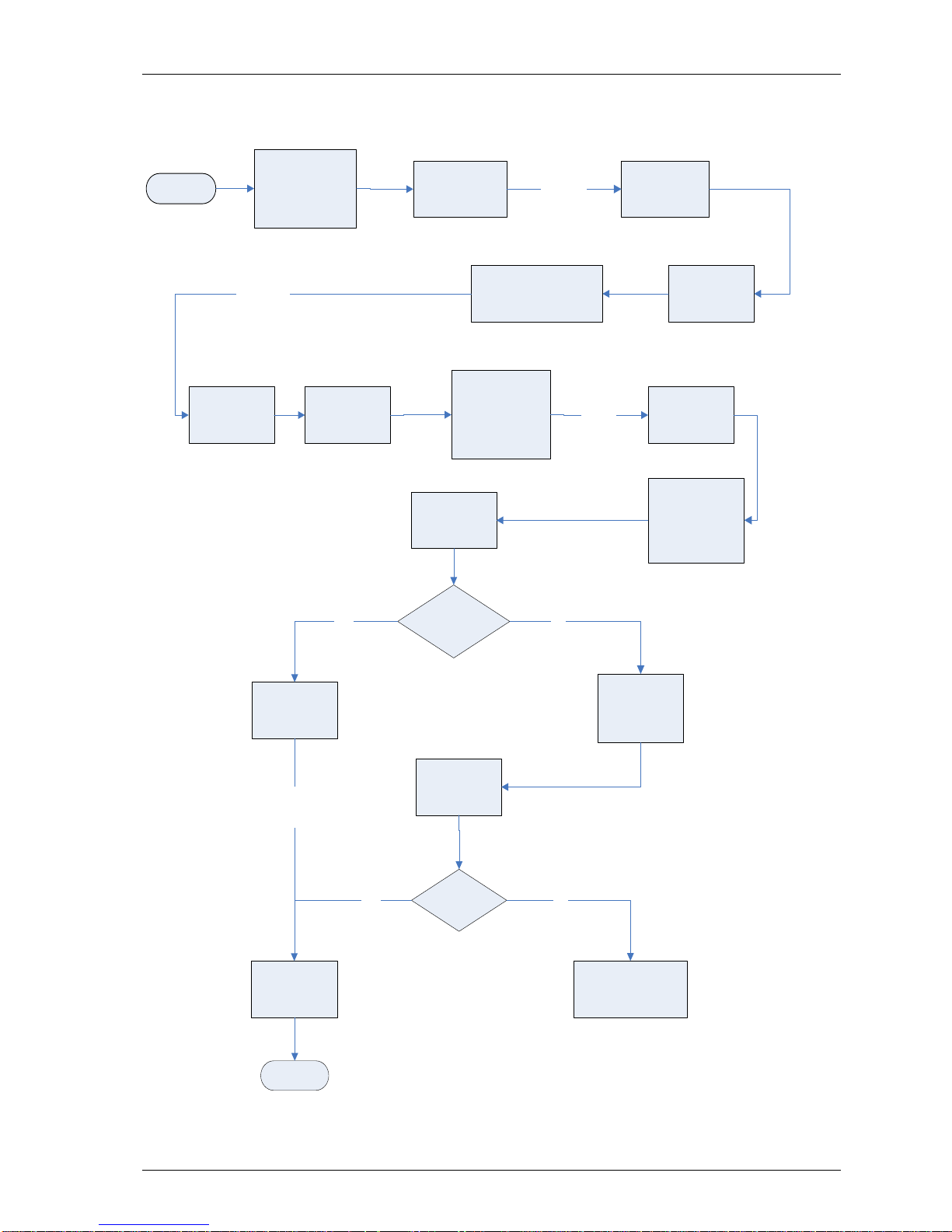
OMGEM5KN4 GEM5000 gas analyser
Page 66 Copyright Geotech
9.7.2 Calibration – mixtures 1, 2, & 3
START
Switch on the
instrument and
complete the
instrument warm up.
Main Gas Read
Screen select the
‘Menu’ key
Select key 2
Gas Check
Select key 2
Gas Check
Connect the flow
regulator to the
white port on the
analyser
Flow certified gas
mixture using the
gas regulator
supplied
Wait for the readings
to stabilise. Wait for
the analyser to
check spans for
approx. 1 minute.
Message will
display ‘Please
wait for timer to
reach zero’
When complete a
message will
display ‘Check
complete’
READ STATUS
FIELD
Select soft-key
‘Calibration’
READ STATUS
FIELD
Status
correct?
Status correct?
(gases ticked)
Calibration result
saved
END
Select
soft-key
‘Operation
Settings’
Select
soft-key
‘Check’
NO
Calibration Successful
YES
Exit
YES
NO
Select correct gas mixture:
1, 2, or 3, or add Userselectable gas mixture
Press
‘Enter’
to confirm
Gas mixture
Select soft-key
‘Retry’
(retry gas check
again)
Contact Geotech
technical support team
for advice
YES
Page 67
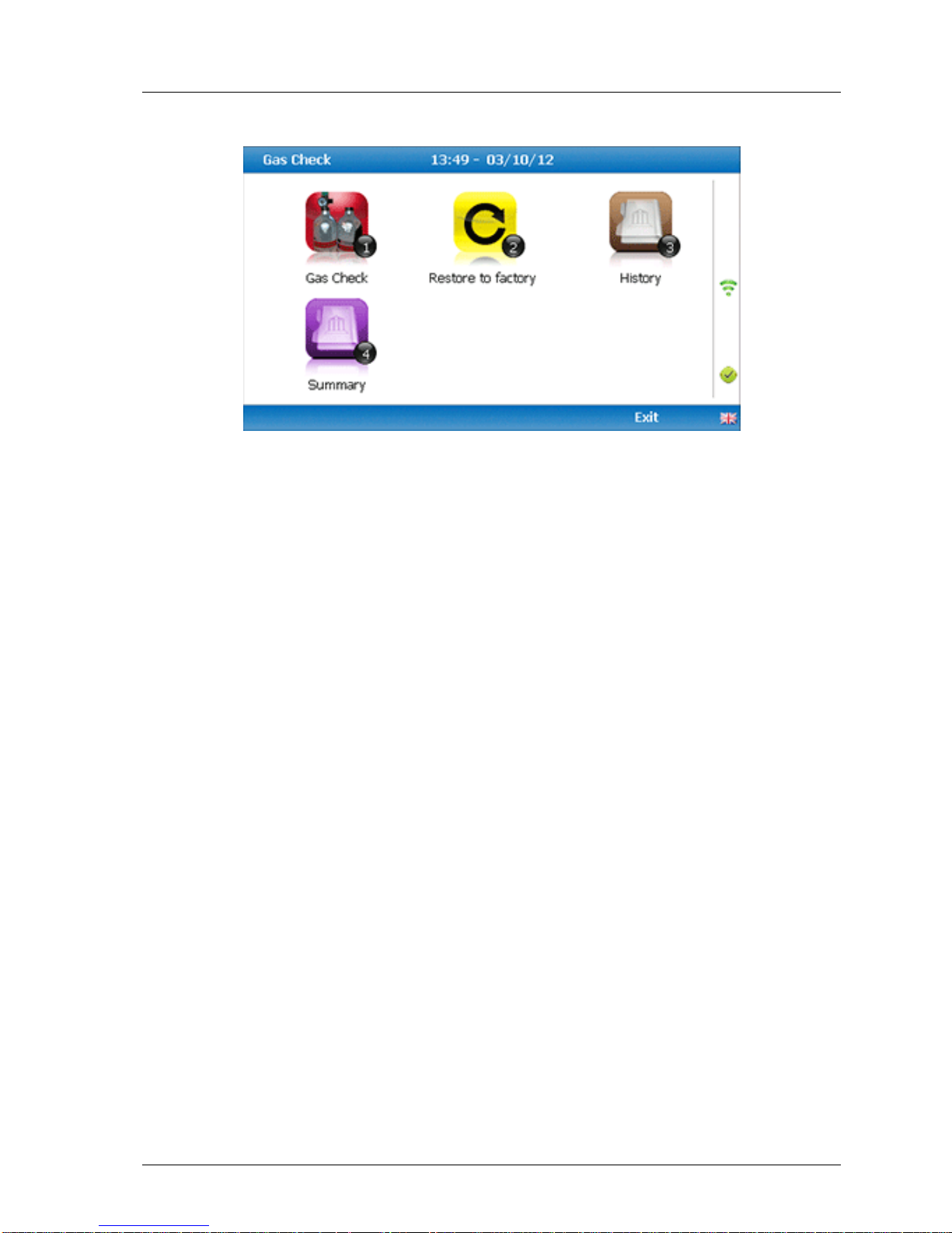
GEM5000 gas analyser OMGEM5KN4
Copyright Geotech Page 67
9.8 Restore to factory
This option will reset the gas analyser to all of its factory programmed calibration settings
and will clear ALL the user defined calibration points. It will not affect or remove ID’s or
readings from the analyser.
1) Select ‘Key 2 - Restore to factory’ followed by the soft-key ‘Confirm’ or ‘Cancel’.
2) A validation message is displayed ‘Reset user calibration?’ Press the soft-key ‘Confirm’
to continue with the factory settings or soft-key ‘Cancel’ to cancel the operation and
return to the Gas Check menu.
9.9 Calibration history
The GEM5000 gas analyser logs user calibrations in ‘History’ application. This can be used
as an aid to ensuring that gas measurements are valid and accurate. Both good and failed
calibration results are recorded for each channel calibrated.
1) Select ‘Key 3 – History’.
2) The operator may view the calibration data stored. Use the soft-key ‘Filter’ to add a
sort filter to the history enquiry.
9.10 Calibration summary
The GEM5000 gas analyser has the facility to log the history of user calibrations.
1) Select ‘Key 4 – Summary’.
2) The operator may view the calibration data history stored by ID, technician,
timestamp, type and calibration result. Use the soft-key ‘Exit’ to exit and return to the
‘Gas Check’ menu.
Page 68

OMGEM5KN4 GEM5000 gas analyser
Page 68 Copyright Geotech
10.0 Problem solving
This section outlines various warning and error messages which the operator may receive
during general operation of the instrument. For further assistance please contact Technical
Support at Geotech on +44(0)1926 338111 or email [email protected].
11.0 Warning and error display
When switched on the instrument will perform a pre-determined self-test sequence taking
approximately 15 seconds. During this time many of the instrument’s working parameters
and settings are checked.
If any operational parameters are out of specification or the pre-programmed
recommended calibration/service date has passed, errors or warnings may be displayed.
Use the ‘Scroll up’ and ‘Scroll down’ keys to move through the list if required.
Only three warnings/errors can be displayed at any time.
To ascertain if more errors have occurred use ‘Key 8’ – Scroll down’ and ‘Key 2’ - Scroll up’
through the list.
Warnings displayed:
All warnings displayed will be prefixed by the word WARNING followed by a relevant
description.
There are two types of warning that may be displayed:
1. General warnings that may not affect the instrument’s function and those where the
self-test has detected a function that is outside the usual programmed operating
criteria, e.g. battery charge low, memory nearly full.
2. Operational parameters that could affect the performance of the analyser: Cell out of
calibration, CH4 out of calibration, CO2 out of calibration.
The most likely reason for the errors is either an incorrect user calibration or sensor
failure. If an incorrect user calibration has caused the warning it should be correctable by
way of returning the instrument to factory settings, zeroing or carrying out a user
calibration as necessary for the relevant function.
Page 69
GEM5000 gas analyser OMGEM5KN4
Copyright Geotech Page 69
12.0 Service
The GEM5000 gas analyser should be regularly serviced to ensure correct and accurate
operation. Geotech recommends a service and recalibration every 6 months.
The GEM5000 range is ATEX certified for use in potentially explosive areas. As such it should
be serviced only by qualified engineers. Failure to observe this will result in the warranty
becoming invalid and could invalidate the ATEX certification.
Warning
If the GEM5000 is serviced by unqualified engineers the ATEX
certification may be invalidated and the instrument may be unsafe
for use in a potentially explosive atmosphere.
User serviceable parts:
There are no user serviceable parts inside the instrument.
The following parts can be user serviced:
In-line water filter
This should be regularly inspected for obstructions, moisture
or damage and changed if needed. The instrument should
never be operated without the in-line water filter as this
may result in water entering the instrument.
Sample tubing
Always ensure that sample tubes are not contaminated or
damaged.
Gas port connectors
Periodically check that the O-rings on the gas port
connectors are not damaged. A damaged O-ring can let air
into the sample gas and result in incorrect readings. If the
O-ring is damaged the complete gas port connector should
be replaced.
H2S filter material
When the filter material changes colour to a light grey colour
the filter should be replaced.
Page 70

OMGEM5KN4 GEM5000 gas analyser
Page 70 Copyright Geotech
13.0 Warranty policy
This instrument is guaranteed, to the original end user purchaser, against defect in materials
and workmanship for a period of 3 years from the date of the shipment to the user.
During this period Geotech will repair or replace defective parts on an exchange basis.
The decision to repair or replace will be determined by Geotech.
To maintain this warranty, the purchaser must perform maintenance and calibration as
prescribed in the operating manual.
Normal wear and tear, and parts damaged by abuse, misuse, negligence or accidents are
specifically excluded from the warranty.
Note: Please contact Technical Support at Geotech for further information.
Page 71
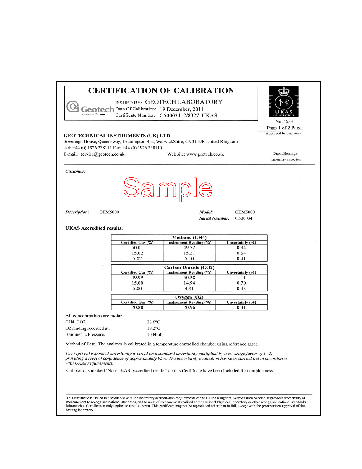
GEM5000 gas analyser OMGEM5KN4
Copyright Geotech Page 71
14.0 Sample certificate of calibration
This is a sample certificate of calibration supplied at the time of purchase and updated when
the instrument is serviced.
Page 72
OMGEM5KN4 GEM5000 gas analyser
Page 72 Copyright Geotech
Page 73

GEM5000 gas analyser OMGEM5KN4
Copyright Geotech Page 73
15.0 Important notice to all customers
WEEE COMPLIANT
The wheelie bin symbol now displayed on equipment supplied by Geotechnical Instruments
(UK) Limited signifies that the apparatus must not be disposed of through the normal
municipal waste stream but through a registered recycling scheme.
The Waste Electrical and Electronic Equipment directive (WEEE) makes producers responsible
from July 1st 2007 in meeting their obligations, with the fundamental aim of reducing the
environmental impact of electrical and electronic equipment at the end of its life.
Geotech is now registered with the Environmental Agency as a producer and has joined a
recycling scheme provider who will manage and report on our electrical waste on our behalf.
Our Producer Registration Number is WEEE/NYN680
When your instrument is at the end of its life, please contact the Sales team at Geotech who
will advise you on the next step in order to help us meet our obligations.
Page 74

OMGEM5KN4 GEM5000 gas analyser
Page 74 Copyright Geotech
16.0 Appendices – safety instructions
16.1 Instructions for safe use – Italian language
Istruzioni per la sicurezza
Avvertenza
Gli analizzatori di gas serie 5000 possono essere utilizzati per
misurare i gas provenienti da discariche o da altre fonti, come
descritto in questo manuale.
L’operatore può essere esposto a gas nocivi durante l’utilizzo
dello strumento. L’inalazione di questi gas può danneggiare la
salute e in alcuni casi essere letale.
Spetta all’utente controllare di essere sufficientemente informato
sugli aspetti riguardanti la sicurezza dei gas utilizzati e di seguire
le procedure appropriate. In particolare nel caso di gas
pericolosi, quelli scaricati dall’analizzatore devono essere
convogliati in un’area in cui lo scaricotale operazione possa
essere effettuatao in condizioni di sicurezza.
È possibile che lo strumento scarichi gas pericolosi anche
durante lo spurgoquando viene utilizzato per spurgare con aria
pulita.
Nota: gli analizzatori di gas sono apparecchi scientifici delicati e vanno trattati come
tali. Utilizzando l’apparecchio in modo diverso da quanto specificato dalla casa
produttrice, l’apparecchio stesso potrebbe non fornire più la protezione
prevista.
Gli analizzatori di gas serie 5000 sono conformi alla Parte 15 delle norme FCC. L’utilizzo è
soggetto alle seguenti due condizioni:
1) il dispositivo non deve causare interferenze dannose
2) il dispositivo deve accettare le interferenze che riceve, anche se possono causare
effetti indesiderati per il suo funzionamento.
Gli analizzatori di gas della serie 5000 sono certificati con riferimento alla
classificazione delle aree pericolose secondo ATEX e IECEx.
II 2G Ex ib IIA T1 Gb (Ta = da -10ºC a +50ºC)
È essenziale seguire scrupolosamente le istruzioni. Spetta all’operatore definire il concetto
di protezione e la classificazione richiesta per una data applicazione.
Istruzioni per l’uso in sicurezza - Italiano
(Riferimento alla Direttiva europea ATEX 94/9/CEC, Allegato II, 1.0.6.)
Le seguenti istruzioni si applicano agli apparecchi coperti dai certificati SIRA 11ATEX2197X
e SIR 11.0089X della Direttiva IECEx:
Gli apparecchi possono essere utilizzati con gas e vapori infiammabili di gruppo IIA e
temperature di classe T1.
Gli apparecchi sono certificati solo per l’uso a temperatura ambiente compresa tra
Page 75

GEM5000 gas analyser OMGEM5KN4
Copyright Geotech Page 75
-10ºC e +50ºC e non vanno utilizzati al di fuori di questo intervallo.
Gli apparecchi non vanno utilizzati in un’atmosfera che contenga più del 21% di
ossigeno.
Le riparazioni di questi apparecchi vanno effettuate in conformità al codice
professionale rilevante.
In aree pericolose, utilizzare solo la sonda di temperatura GF5.2 (SIRA 11ATEX2197X
e IECEx SIR11.0089X). Per il connettore C, l’anemometro GF5.4 (BVS 04ATEXE194)
da usare esclusivamente con apparecchi ATEX. Nella zona pericolosa, l’analizzatore
non va collegato ad altri dispositivi in dotazione, come il cavo GF-USB (per il
connettore A) o il caricabatteria GF3.9 (per il connettore B).
Non caricare, ricaricare o aprire in un’atmosfera potenzialmente esplosiva.
In aree pericolose, utilizzare solo la “sonda di temperatura GF5.2” con il connettore
B.
Connettore C (Uo=10V,lo=5mA,Po=50mW,Ci=0,Li=0,Co=100uF,Lo=1000mH),
Connettore B (Uo=5V,lo=6mA,Po=7mW,Ci=0,Li=0,Co=100uF,Lo=1000mH)
ALIMENTAZIONI MASSIME NON PERICOLOSE:
Connettore A - Um=6V Connettore B - Um=10,1V
Se esiste la possibilità che l’apparecchio potrebbe venirevenga in contatto con
sostanze aggressive, ad esempio liquidi acidi o gas che possono attaccare i metalli o
solventi che possono agire su materiali polimerici, spetta all’utente adottare le
precauzioni necessarie, ad es. controlli regolari come da programma o verifica della
resistenza a sostanze chimiche specifiche consultando la scheda tecnica, per evitare
effetti negativi e non compromettere il tipo di protezione di cui è dotato
l’apparecchio.
L’intervallo di pressione relativa è di +/-500 mbar. Si noti tuttavia che la pressione in
entrata non deve superare +/- 500 mbar relativamente alla pressione atmosferica e
la pressione in uscita non deve superare +/- 100 mbar relativamente alla pressione
atmosferica.
Gli analizzatori di gas della serie 5000 sono certificati con riferimento alla
classificazione delle aree pericolose secondo CSA (Canada)
CLASSE 2258 03 - APPARECCHIATURE DI CONTROLLO DEI PROCESSI - Sistemi
intrinsecamente sicuri e ignifughi - Per luoghi pericolosi.
Ex ib IIA
Rilevatori di metano Modello GA 5000, GEM 5000 e BIOGAS 5000; portatili, a batteria, con
pacco batterie non sostituibile sul campo, cod. parte 20087 o 2011113; intrinsecamente
sicuri, per circuiti intrinsecamente sicuri (“[ib]” per Zona 1) fino alla sonda di temperatura
Modello GF5.2 (Connettore B) e con parametri di entità in uscita come indicato nella
tabella sottostante; Codice temperatura T1; -10 ºC Tamb. +50ºC.
Page 76

OMGEM5KN4 GEM5000 gas analyser
Page 76 Copyright Geotech
Connettore
Parametri entità
Uo
(V)
Io
(mA)
Po
(mW)
Co
(uF)
Lo
(mH)
Ci
(uF)
Li
(mH)
B
5.0 6 7
100
1000
0
0
C
10,0
5
50
100
1000
0
0
Nota: questo dispositivo è stato controllato solo per quanto riguarda le
caratteristiche di sicurezza elettrica.
Gli analizzatori di gas della serie 5000 sono certificati con riferimento alla
classificazione delle aree pericolose secondo CSA (USA)
CLASSE 2258 83 - APPARECCHIATURE DI CONTROLLO DEI PROCESSI - Sistemi
intrinsecamente sicuri e ignifughi - Per luoghi pericolosi - CERTIFICATE PER USA NORME
AEx ib IIA
Rilevatori di metano Modello GA 5000, GEM 5000 e BIOGAS 5000; portatili, a batteria, con
pacco batterie non sostituibile sul campo, cod. parte 20087 o 2011113; intrinsecamente
sicuri, per circuiti intrinsecamente sicuri (“[ib]” per Zona 1) fino alla sonda di temperatura
Modello GF5.2 (Connettore B) e con parametri di entità in uscita come indicato nella
tabella sottostante; Codice temperatura T1; -10 ºC Tamb. +50ºC.
Connettore
Parametri entità
Uo
(V)
Io
(mA)
Po
(mW)
Co
(uF)
Lo
(mH)
Ci
(uF)
Li
(mH)
B
5,0 6 7
100
1000
0
0
C
10,0
5
50
100
1000
0
0
Nota: questo dispositivo è stato controllato solo per quanto riguarda le
caratteristiche di sicurezza elettrica.
MCERTS
MCERTS sta per Monitoring Certification Scheme, il programma di certificazione della
Environment Agency, l’enteistituzione britannicoa per la protezione ambientale. Il
programma offre uno schema in base al quale effettuare le misurazioni ambientali
rispettando i requisiti qualitativi dell’Environment Agency e comprende varie attività di
monitoraggio, campionatura e ispezione.
Lo strumento GEM5000 ha la certificazione MCERTS solo se:
Dopo l’accensione iniziale, sullo schermo compare il logo MCERTS.
Nota: MCERTS - Su questo strumento non si sono effettuati test di sensibilità
incrociata con l’utilizzo di idrogeno solforato. Pertanto gli utenti devono
accertare la presenza di H2S, che potrebbe avere un effetto interferenziale.
MCERTS promuove fiducia nel monitoraggio dei dati e offre al settore una struttura
sperimentata per scegliere sistemi e servizi di monitoraggio che soddisfino i requisiti
dell’Environment Agency.
Page 77
GEM5000 gas analyser OMGEM5KN4
Copyright Geotech Page 77
L’Environment Agency ha istituito il Monitoring Certification Scheme (MCERTS) per
conseguire misurazioni ambientali qualitativamente valide. Il programma MCERTS offre la
certificazione dei prodotti secondo gli standard qualitativi dell'Environment Agency, in base
alle norme CEN, ISO e nazionali.
Gli strumenti con certificazione MCERTS sono stati testati da un organismo indipendente
per verificare che soddisfino determinate caratteristiche di prestazione. Inoltre le aziende
dei prodotti MCERTS vengono regolarmente controllate per accertare che le caratteristiche
di prestazione da attestare nel certificato siano sempre conseguite.
Gli analizzatori di gas della serie 5000 sono stati certificati secondo la versione 3.1 delle
‘Caratteristiche di prestazione dei sistemi portatili di monitoraggio delle emissioni’.
Batteria e ricarica
La batteria utilizzata negli analizzatori di gas della serie 5000 è al nichel-idruro metallico e
viene prodotta come pacco con sei celle individuali. Anche se questo tipo di batteria non è
soggetta all’‘effetto memoria’ della ricarica come quelle al nichel cadmio, non è
consigliabileraccomandabile effettuare piccole ricariche parziali.
Il caricabatteria va scollegato solo quando indica la carica completa.
Avvertenza
Il caricabatteria NON è coperto dalla certificazione Ex. La
batteria va caricata solo in un'area sicura.
Il caricabatteria è intelligente e indica lo stato di carica in corso o avvenuta.
Lo strumento va caricato utilizzando ESCLUSIVAMENTE il caricabatteria fornito in
dotazione, che è inteso solo per l’uso in un locale interno. Effettuare la ricarica in un
locale ventilato.
Caricabatteria: Tensione d’ingresso: 100-240V CA +/- 10%
Frequenza d’ingresso: 50-60Hz +/- 10%
Corrente d’ingresso: 0,4A@100VCA .. 0,2A@240VCA
Tensione d’uscita: 10,1VCC max
Corrente d’uscita: 1,5A max
Nota: collegare il caricabatteria all’elettricità di rete utilizzando l’adattatore
necessario. Per ulteriori informazioni rivolgersi alla casa produttrice.
Istruzioni per la pulizia
NON utilizzare detergenti per pulire l’analizzatore o il caricabatteria, perché potrebbero
avere un effetto negativo sulla sicurezza del loro uso.
Prassi ottimali per rilevare le letture
Avvertenza
L’inalazione del gas di solfuro d’idrogeno (H2S) o di altri gas nocivi
può causare la morte. Spetta all’utente accertarsi di essere
sufficientemente addestrato negli aspetti della sicurezza relativi
all’uso di H2S e altri gas nocivi. In particolare nel caso di gas
pericolosi, quelli scaricati dall’analizzatore devono essere convogliati
in un’area in cui lo scaricotale operazione possa essere effettuatao in
condizioni di sicurezza. È possibile che lo strumento scarichi gas
Page 78
OMGEM5KN4 GEM5000 gas analyser
Page 78 Copyright Geotech
pericolosi anche durante lo spurgoquando viene utilizzato per
spurgare con aria pulita.
Prassi ottimali
Nel recarsi al luogo di utilizzo, collocare l'analizzatore di gas nell’abitacolo del veicolo,
non nel bagagliaio, dove potrebbe essere soggetto a estremi di temperatura e
danneggiarsi per eventuali urti. Non appoggiare l’analizzatore di gas contro superfici calde
(ad es. tubo di aspirazione del gas, carrozzeria di un’autovettura o interno di
un’autovettura incustodita in estate), perché ciò fa aumentare la temperatura
dell’analizzatore di gas e può falsare le letture.
Negli spostamenti nell'area di utilizzo dell'analizzatore di gas, proteggerlo dalla luce
diretta del sole e dagli scrosci di pioggia.
Usare sempre il sifone per lo scarico della condensa!. Se il sifone si allaga, cambiare il
filtro e controllare che tutti i tubi siano liberi dalla condensa prima di riutilizzarlo
Nota: se lo scarico di un analizzatore di gas serie GA5000 è collegato ad un
sistema pressurizzato, ciò fa uscire un flusso di gas dall’entrata.
Taratura
Avvertenza
I gas di taratura possono essere pericolosi.
Per ciascun gas da utilizzare, leggere preventivamente la
relativa scheda tecnica di sicurezza, accertandosi di
comprenderne il contenuto.
Il regolatore fornito col kit di taratura è stato configurato per permettere l’erogazione di un
flusso fisso.
Dato che il flusso del regolatore è impostato in fabbrica, può essere aperto con una
semplice rotazione, senza effettuare regolazioni.
Avvertenza
Luce di scarico
Durante la taratura dell’analizzatore, vi sono due possibili
uscite per il gas: come di norma dalla luce di scarico
(gialla)dell’analizzatore o, in caso di sovrapressione, dalla
luce di 1/16” della valvola limitatrice di pressione rossa
situata sul regolatore.
Si raccomanda che entrambe le luci siano dotate di tubi di
scarico,
che devono sboccare in un’area ben ventilata. Controllare
che i tubi e i raccordi non presentino perdite.
La taratura dell’analizzatore di gas va eseguita in un’area
idonea, adottando tutte le precauzioni necessarie per l’utilizzo
di gas potenzialmente pericolosi, esplosivi o tossici.
Nota: è possibile anche che il gas esca dall’uscita del flusso interno (blu)
dell’analizzatore di gas (vale solo per GA5000).
Page 79
GEM5000 gas analyser OMGEM5KN4
Copyright Geotech Page 79
Manutenzione
Gli analizzatori di gas della serie 5000 devono essere sottoposti a regolare controllo di
manutenzione per accertare che il funzionamento sia corretto e preciso. Geotech
raccomanda che la manutenzione e la taratura siano effettuate ogni 6 mesi.
Gli analizzatori di gas della serie 5000 hanno la certificazione ATEX per l’utilizzo in aree
potenzialmente esplosive. In quanto tali, la loro manutenzione deve essere affidata
esclusivamente a tecnici qualificati. La mancata osservanza di questa regola invalida la
garanzia ed eventualmente anche la certificazione ATEX.
Avvertenza
Se la manutenzione dell’analizzatore di gas viene
effettuata da tecnici non qualificati, la certificazione ATEX
può venirne compromessa, pregiudicando così l’utilizzo in
condizioni di sicurezza dello strumento in un’atmosfera
potenzialmente esplosiva.
Parti riparabili dall’utente:
Non vi sono parti riparabili dall’utente all’interno dello strumento.
Le parti seguenti possono essere riparate:
Filtro acqua in linea
Va controllato regolarmente per evidenziare eventuali
ostruzioni, condensa o danneggiamenti e sostituito se
necessario. Lo strumento non va mai usato senza il filtro
in linea, per evitare possibili infiltrazioni dperché vi
entrerebbe l’acqua.
Tubi di campionamento
Controllare sempre che i tubi di campionamento non
siano contaminati o danneggiati.
Raccordi del gas
Controllare periodicamente che i gommini O-ring dei
raccordi del gas non siano danneggiati. Se danneggiati,
gli O-ring lasciano entrare aria nei tubi di
campionamento, sfalsando le letture. Se l’O-ring risulta
danneggiato, è necessario sostituire tutto il raccordo.
Materiale del filtro H2S
Quando il materiale del filtro cambia colore e diventa
grigio chiaro, il filtro va sostituito.
Dichiarazione di conformità – Italiano
Prodotti
GA5000 – Analizzatore di gas per discariche
GEM5000 - Analizzatore di gas e monitor di estrazione per
discariche e monitor per l’estrazione
BIOGAS 5000 – Analizzatore di gas per impianti di digestione
anaerobica
Geotechnical Instruments (UK) Limited dichiara che gli articoli sopra descritti sono
conformi ai seguenti standard:
Direttiva ATEX 94/9/CE
Page 80

OMGEM5KN4 GEM5000 gas analyser
Page 80 Copyright Geotech
Organismo di certificazione
SIRA Certification Service Servizio di certificazione SIRA
Numero dell’organismo
notificato
0518
Indirizzo
Rake Lane, Eccleston, Chester, CH4 9JN, GB
N° certificazione SIRA
SIRA 11ATEX2197X
Norme applicate
EN60079-0 :2006
EN60079-0 :2009
EN60079-11 :2007
IECEx
Organismo di certificazione
SIRA Certification Service Servizio di certificazione SIRA
Numero dell’organismo
notificato
0518
Indirizzo
Rake Lane, Eccleston, Chester, CH4 9JN, GB
N° certificazione IECEx
SIR 11.0089X
Norme applicate
IEC60079-0 :2004 Ed4
IEC60079-0 :2007 Ed5
IEC60079-11 :2006 Ed5
CSA (Canada e USA)
Organismo di certificazione
CSA International
Indirizzo
178 Rexdale Boulevard, Toronto, ON, Canada M9W 1R3
N° certificazione CSA
CSA 11 2445306
Norme applicate
C22.2 No. 0-10 - Requisiti generali – Codice elettrico
canadese, Parte II
CAN/CSA-C22.2 No. 60079-0:07 - Apparecchi elettrici per
atmosfere con gas esplosivi - Parte 0: Requisiti generali
CAN/CSA-C22.2 No. 60079-1:07 - Apparecchi elettrici per
atmosfere con gas esplosivi - Parte 1: Custodie a prova
di esplosione "d"
CAN/CSA-E60079-11:02 - Apparecchi elettrici per
atmosfere con gas esplosivi - Parte 11: Sicurezza
intrinseca "i"
ANSI/UL 60079-0:09 - Apparecchi elettrici per atmosfere
con gas esplosivi - Parte 0: Requisiti generali
ANSI/UL 60079-1:09 - Apparecchi elettrici per atmosfere
con gas esplosivi - Parte 1: Custodie a prova di
Page 81

GEM5000 gas analyser OMGEM5KN4
Copyright Geotech Page 81
esplosione "d"
ANSI/UL 60079-11:09 - Apparecchi elettrici per
atmosfere con gas esplosivi - Parte 11: Sicurezza
intrinseca "i"
Direttiva EMC 2004/108/CE
EN 301 489 P. 1 (V1.9.1 – 2011-04)
EN 301 489 P. 17 (V2.1.1 – 2009-05)
EN 301 489 P. 19 (V1.2.1 – 2002-11)
BS EN 61000-3-2: 2006 + A2:2009
BS EN 61000-3-3: 2008
Compatibilità elettromagnetica e questioni
relative allo spettro delle radiofrequenze (ERM)
Norma di compatibilità elettromagnetica (EMC)
per apparecchiature e servizi radio
Parte 1: Prescrizioni tecniche comuni
Compatibilità elettromagnetica e questioni
relative allo spettro delle radiofrequenze (ERM)
Norma di compatibilità elettromagnetica (EMC)
per apparecchiature radio
Parte 17: Condizioni specifiche per sistemi di
trasmissione dati su banda larga
EMC per sistemi di trasmissione dati su
banda larga
Compatibilità elettromagnetica e questioni
relative allo spettro delle radiofrequenze (ERM)
Norma di compatibilità elettromagnetica (EMC)
per apparecchiature e servizi radio
Parte 19: Condizioni specifiche per soli ricevitori
di stazioni mobili terrestri (ROMES) operativi nella
banda 1,5 GHz che forniscono comunicazioni di
dati
EMC per soli ricevitori di stazioni mobili terrestri
(ROMES)
Limiti di compatibilità elettromagnetica (EMC) .
Limiti per le emissioni di corrente armonica
(apparecchiature con corrente di ingresso ≤ 16 A
per fase)
Limiti di compatibilità elettromagnetica (EMC) .
Limitazione delle fluttuazioni di tensione e del
flicker in sistemi di alimentazione in bassa
tensione per apparecchiature con corrente
nominale ≤ 16 A e non soggette ad allacciamento
su condizione
Firmato
Dr. Roger Riley
Page 82

OMGEM5KN4 GEM5000 gas analyser
Page 82 Copyright Geotech
16.2 Instructions for safe use – German language
Sicherheitsvorschriften
Warnhinweise
Die Gasanalysatoren der 5000er Serie können zum Messen der
Gase von Deponien und anderen Quellen wie in diesem
Handbuch beschrieben verwendet werden.
Der Bediener kann bei Verwendung des Geräts schädlichen
Gasen ausgesetzt werden. Das Einatmen dieser Gase kann
gesundheitsschädlich und in manchen Fällen sogar tödlich sein.
Es liegt in der Verantwortung des Benutzers sicherzustellen,
dass er/sie angemessen über die Sicherheitsaspekte der
eingesetzten Gase geschult ist und geeignete Verfahren befolgt
werden. Vor allem beim Einsatz gefährlicher Gase muss das
vom Analysator ausströmende Gas in einen Bereich geleitet
werden, in dem das Gas sicher abgeführt werden kann.
Gefährliches Gas kann ebenso vom Gerät ausgestoßen werden,
wenn es mit sauberer Luft gereinigt wird.
Hinweis: Gasanalysatoren sind empfindliche wissenschaftliche Geräte und sollten
entsprechend behandelt werden. Wenn das Gerät anders als vom
Hersteller spezifiziert verwendet wird, kann der vom Gerät gebotene
Schutz beeinträchtigt werden.
Die Gasanalysatoren der 5000er Serie erfüllen Abschnitt 15 der FCC-Vorschriften. Der
Betrieb unterliegt den folgenden zwei Bedingungen:
1) Dieses Gerät darf keine schädlichen Funkstörungen verursachen.
2) Dieses Gerät muss mögliche empfangene Funkstörungen und dadurch verursachte
Funktionsstörungen dulden.
Für ATEX und IECEx sind die Gasanalysatoren der 5000er Serie für den Einsatz in
explosionsgefährdeten Bereichen zertifiziert.
II 2G EX ib IIA T1 Gb (Ta = -10°C bis +50°C)
Die Vorschriften müssen unbedingt genau befolgt werden. Es liegt in der Verantwortung
des Betreibers, das Schutzkonzept und die erforderliche Schutzklasse für eine bestimmte
Anwendung festzulegen.
Vorschriften zur sicheren Verwendung - Deutsch
(Siehe Europäische ATEX-Richtlinie 94/9/EC, Anhang II, 1.0.6.)
Die folgenden Vorschriften gelten für Geräte, die in den Zertifikaten Nr. SIRA
11ATEX2197X und IECEx Richtlinie SIR 11.0089X behandelt werden:
Die Geräte dürfen mit brennbaren Gasen und Dämpfen mit Apparategruppe IIA und
Temperaturklasse T1 eingesetzt werden.
Die Geräte sind nur für den Einsatz bei Umgebungstemperaturen im Bereich von -10
°C bis +50 °C zertifiziert und sollten nicht außerhalb dieses Bereichs eingesetzt
werden.
Page 83

GEM5000 gas analyser OMGEM5KN4
Copyright Geotech Page 83
Die Geräte dürfen nicht in einer Atmosphäre mit mehr als 21 % Sauerstoffgehalt
eingesetzt werden.
Die Reparatur dieser Geräte darf nur entsprechend der maßgeblichen Anleitung
durchgeführt werden.
Bei Einsatz in einem explosionsgefährdeten Bereich darf nur Temperaturfühler GF5.2
(SIRA 11ATEX2197X und IECExSIR11.0089X) verwendet werden. Anemometer
GF5.4 (BVS 04ATEXE194), nur für den Einsatz mit ATEX, in Anschluss C. Der
Analysator darf nicht an andere Geräte im explosionsgefährdeten Bereich
angeschlossen werden, einschließlich des im Lieferumfang enthaltenen GF-USBKabels (Anschluss A) bzw. Ladegeräts GF3.9 (Anschluss B).
In einer explosionsgefährdeten Atmosphäre nicht laden, wieder aufladen oder
öffnen.
In einem explosionsgefährdeten Bereich nur „Temperaturfühler GF5.2“ in Anschluss
B verwenden.
Anschluss C (Uo=10 V, lo=5 mA, Po=50 mW, Ci=0, Li=0, Co=100 uF, Lo=1000 mH),
Anschluss B (Uo=5 V, lo=6 mA, Po=7 mW, Ci=0, Li=0, Co=100 uF, Lo=1000 mH)
MAXIMALE VERSORGUNG IN NICHT EXPLOSIONSGEFÄHRDETEN BEREICHEN:
Anschluss A - Um=6 V Anschluss B - Um=10,1 V
Falls die Möglichkeit besteht, dass die Geräte mit aggressiven Substanzen in
Berührung kommen, z. B. mit sauren Flüssigkeiten oder Gasen, die Metalle angreifen
können, oder mit Lösungsmitteln, die Polymerwerkstoffe schädigen können, liegt es
in der Verantwortung des Benutzers, geeignete Sicherheitsvorkehrungen zu treffen,
z. B. regelmäßige Kontrollen als Teil der Routineinspektionen oder die Prüfung des
Materialdatenblatts darauf, ob das Gerät mit speziellen Chemikalien kompatibel ist,
die es vor Schäden schützen, um zu gewährleisten, dass diese Art des Schutzes nicht
beeinträchtigt wird.
Der relative Druckbereich ist +/-500 mbar. Es ist jedoch zu beachten, dass der
Eingangsdruck +/- 500 mbar relativ zum Atmosphärendruck nicht überschreiten
darfund dass der Ausgangsdruck +/- 100 mbar relativ zum Atmosphärendruck nicht
überschreiten darf.
Für CSA (Kanada) sind die Gasanalysatoren der 5000er Serie für den Einsatz in
explosionsgefährdeten Bereichen zertifiziert.
KLASSE 2258 03 - PROZESSKONTROLLGERÄT - Eigensichere und nicht zündgefährliche
Systeme - Für explosionsgefährdete Standorte
Ex ib IIA:
Methandetektoren Modell GA 5000, GEM 5000 und BIOGAS 5000; tragbar,
batteriebetrieben mit nicht im Feld austauschbarem Akkupack Teilenr. 20087 oder
2011113; eigensicher, bietet eigensichere Kreise („[ib]“ für Zone 1) für Temperaturfühler
Page 84

OMGEM5KN4 GEM5000 gas analyser
Page 84 Copyright Geotech
Modell GFS.2 (Anschluss B), mit Entitätsausgabenparameter wie unten aufgeführt;
Temperaturcode T1; -10 °C Tamb. +50 °C.
Anschluss
Entitätsparameter
Uo
(V)
Io
(mA)
Po
(mW)
Co
(uF)
Lo
(mH)
Ci
(uF)
Li
(mH)
B
5,0 6 7
100
1000
0
0
C
10,0
5
50
100
1000
0
0
Hinweis: Dieses Gerät wurde nur auf elektrische Sicherheitsfunktionen untersucht.
Für CSA (USA) sind die Gasanalysatoren der 5000er Serie für den Einsatz in
explosionsgefährdeten Bereichen zertifiziert.
KLASSE 2258 83 - PROZESSKONTROLLGERÄT - Eigensichere und nicht zündgefährliche
Systeme - Für explosionsgefährdete Standorte - NACH US-AMERIKANISCHEN NORMEN
ZERTIFIZIERT
AEx ib IIA:
Methandetektoren Modell GA 5000, GEM 5000 und BIOGAS 5000; tragbar,
batteriebetrieben mit nicht im Feld austauschbarem Akkupack Teilenr. 20087 oder
2011113; eigensicher, bietet eigensichere Kreise („[ib]“ für Zone 1) für Temperaturfühler
Modell GFS.2 (Anschluss B), mit Entitätsausgabenparameter wie unten aufgeführt;
Temperaturcode T1; -10 °C Tamb. +50 °C.
Anschluss
Entitätsparameter
Uo
(V)
Io
(mA)
Po
(mW)
Co
(uF)
Lo
(mH)
Ci
(uF)
Li
(mH)
B
5,0 6 7
100
1000
0
0
C
10,0
5
50
100
1000
0
0
Hinweis: Dieses Gerät wurde nur auf elektrische Sicherheitsfunktionen untersucht.
MCERTS
MCERTS ist das Monitoring Certification Scheme (Zertifizierungsprogramm für
Überwachungsgeräte) der britischen Umweltagentur. Das Programm bietet einen Rahmen,
in dem Umgebungsmessungen gemäß den Qualitätsanforderungen der Agentur
durchgeführt werden können. Es umfasst eine Reihe von Überwachungs-, Probenahmeund Prüfaufgaben.
Das Instrument GEM5000 ist nur MCERTS-zertifiziert, falls:
Das MCERTS-Logo nach dem erstmaligen Einschalten auf dem Bildschirm erscheint.
Hinweis: MCERTS - Bei diesem Gerät wurden keine Störempfindlichkeitsprüfungen
mit Schwefelwasserstoff durchgeführt. Daher sollten Benutzer wissen, ob
H2S vor Ort vorhanden ist, da dies eine Störwirkung zur Folge haben
könnte.
MCERTS fördert das öffentliche Vertrauen in Überwachungsdaten und liefert der Industrie
einen erprobten Rahmen zur Auswahl von Überwachungssystemen und -dienstleistungen,
Page 85
GEM5000 gas analyser OMGEM5KN4
Copyright Geotech Page 85
die die Leistungsanforderungen der Umweltagentur erfüllen.
Die britische Umweltagentur hat MCERTS (Monitoring Certification Scheme) initiiert, um
hochwertige Umweltmessungen bereitzustellen. Das MCERTS
Produktzertifizierungsprogramm ermöglicht die Zertifizierung von Produkten gemäß den
Leistungsstandards der Umweltagentur basierend auf den entsprechenden CEN-, ISO- und
nationalen Normen.
MCERTS-zertifizierte Geräte wurden durch eine unabhängige Stelle geprüft, um zu
gewährleisten, dass bestimmte Leistungsanforderungen erfüllt werden. Darüber hinaus
wird der Hersteller eines MCERTS-Produkts regelmäßig geprüft, um zu gewährleisten, dass
die Leistungsanforderungen der Zertifizierung durchgehend erfüllt werden.
Die Gasanalysatoren der 5000er Serie wurden gemäß Version 3.1 der
„Leistungsanforderungen für tragbare Emissionsüberwachungssysteme“ zertifiziert.
Akku und Aufladen
Bei dem Akku, der in den Gasanalysatoren der 5000er Serie verwendet wird, handelt es
sich um einen Nickel-Metallhydrid-Akku, der als Akkupack aus sechs einzelnen Zellen
hergestellt wird. Dieser Akkutyp ist weniger stark für den Memoryeffekt anfällig als NickelKadmium-Akkus. Trotzdem wird davon abgeraten, das Gerät mit kleinen Ladungen
nachzuladen.
Das Ladegerät sollte nur getrennt werden, wenn komplette Ladung angezeigt wird.
Warnhinweise
Das Akkuladegerät ist NICHT in der ATEX-Zertifizierung
enthalten. Der Akku darf nur in einem sicheren Bereich
aufgeladen werden.
Das Akkuladegerät ist intelligent und zeigt an, wenn die Einheit aufgeladen wird bzw. wenn
sie vollständig aufgeladen ist.
Das Gerät darf NUR mit dem mitgelieferten Akkuladegerät aufgeladen werden. Das
Akkuladegerät ist nur für den Gebrauch in Innenräumen vorgesehen. Bitte sorgen Sie für
ausreichende Belüftung während des Aufladens.
Ladegerät: Eingangsspannung: 100-240 V AC +/- 10 %
Eingangsfrequenz: 50-60 Hz +/- 10 %
Eingangsstromstärke: 0,4 A bei 100 VAC .. 0,2 A bei 240 VAC
Ausgangsspannung: Max. 10,1 VDC
Ausgangsstromstärke: Max. 1,5 A
Hinweis: Schließen Sie das Ladegerät durch Verbinden des entsprechenden Adapters
an das Stromnetz an. Wenden Sie sich für weitere Informationen an den
Hersteller.
Reinigungsanweisungen
Ve vrwenden Sie KEINE Reinigungsmittel zum Reinigen des Analysegeräts oder
Akkuladegeräts, da sie die sichere Verwendung dieser Geräte beeinträchtigen können.
Good Practice beim Ablesen
Warnhinweise
Das Einatmen von Schwefelwasserstoffgas (H2S) oder anderer
Page 86
OMGEM5KN4 GEM5000 gas analyser
Page 86 Copyright Geotech
schädlicher Gase kann tödlich sein. Es liegt in der
Verantwortung des Benutzers sicherzustellen, dass er/sie
angemessen über die Sicherheitsaspekte beim Einsatz von H2S
und anderer schädlicher Gase geschult ist. Vor allem beim
Einsatz gefährlicher Gase muss das vom Analysator
ausströmende Gas in einen Bereich geleitet werden, in dem das
Gas sicher abgeführt werden kann. Gefährliches Gas kann
ebenso vom Gerät ausgestossen werden, wenn es mit sauberer
Luft ausgeblasen wird.
Good Practice
Transportieren Sie den Gasanalysator im Inneren des Fahrzeugs an den Einsatzort -
nicht auf der Ladefläche, wo er Temperaturschwankungen und möglichen Stößen
ausgeliefert ist. Platzieren Sie den Gasanalysator nicht direkt an oder auf etwas
Heißem (z. B. Gasleitung, Karosserie oder in einem unbeaufsichtigten Auto während
des Sommers), da dies einen Temperaturanstieg im Gasanalysator verursacht und zu
fehlerhaften Messwerten führen kann.
Schützen Sie den Gasanalysator am Einsatzort vor starkem, direktem Sonnenlicht
und starkem Regen.
Verwenden Sie stets den Wasserabscheider! Wenn der Wasserabscheider überschwemmt
wird, tauschen Sie den Filter aus, und stellen Sie sicher, dass alle Schläuche frei von
Feuchtigkeit sind, bevor Sie sie erneut verwenden.
Hinweis: Wenn der Auslass eines Gasanalysators der Serie GA5000 an ein
druckbeaufschlagtes System angeschlossen ist, dann führt dies zu einem
Gasstrom aus dem Einlassstromanschluss.
Kalibrieren
Warnhinweise
Eichgase können gefährlich sein.
Vor dem Verfahren müssen die
Materialsicherheitsdatenblätter aller verwendeten Gase
gelesen und verstanden werden.
Der mit dem Kalibrierset gelieferte Regulator wurde so konfiguriert, dass er einen
unveränderlichen Durchfluss liefert.
Da der Durchfluss des Regulators werkseitig eingestellt ist, lässt der Regulator sich mit nur
wenigen Drehungen öffnen; eine Einstellung ist nicht erforderlich.
Warnhinweise
Austrittsöffnung
Wenn der Gasanalysator kalibriert wird, gibt es zwei
mögliche Ausgänge für das Gas: auf die übliche Art über
die Austrittsöffnung (gelb) des Analysators oder bei
Überdruck über die 1/16”Öffnung des roten
Druckentlastungsventils, das sich am Regler befindet.
Für beide Öffnungen wird das Anbringen von
Auslassrohrleitungen empfohlen.
Die Auslassrohrleitungen müssen in einen gut belüfteten
Bereich führen. Stellen Sie sicher, dass es in den
Page 87

GEM5000 gas analyser OMGEM5KN4
Copyright Geotech Page 87
Rohrleitungen und an den Verbindungen keine
Undichtigkeiten gibt.
Das Kalibrieren des Gasanalysators muss in einem
sicheren Bereich unter Anwendung aller notwendigen
Sicherheitsvorkehrungen durchgeführt werden, wenn
möglicherweise gefährliche, explosive oder toxische Gase
eingesetzt werden.
Hinweis: Es besteht außerdem die Möglichkeit, dass Gas aus dem internen
Strömungsanschluss (blau) des Gasanalysators ausgestoßen wird (gilt nur
für GA5000).
Wartung
Die Gasanalysatoren der 5000er Serie müssen regelmäßig gewartet werden, um den
korrekten und genauen Betrieb zu gewährleisten. Geotech empfiehlt ein Wartungs- und
Neukalibrierungsintervall von 6 Monaten.
Die Gasanalysatoren der 5000er Serie sind für den Einsatz in explosionsgefährdeten
Bereichen ATEX-zertifiziert. Daher dürfen sie nur von qualifizierten Technikern gewartet
werden. Im Falle der Nichtbefolgung erlischt die Garantie, und die ATEX-Zertifizierung
kann ihre Gültigkeit verlieren.
Warnhinweise
Falls derGasanalysator von unqualifizierten Technikern
gewartet wird, kann die ATEX-Zertifizierung ihre
Gültigkeit verlieren, und das Gerät ist möglicherweise
für den Einsatz in einer explosionsgefährdeten
Atmosphäre nicht mehr sicher.
Teile, die durch den Benutzer gewartet werden können:
Im Gerät gibt es keine Teile, die durch den Benutzer gewartet werden können.
Die folgenden Teile können durch den Benutzer gewartet werden:
Wasserleitungsfilter
Er muss regelmäßig auf Verstopfungen, Feuchtigkeit
bzw. Beschädigungen untersucht und, falls erforderlich,
ausgetauscht werden. Das Gerät darf nie ohne den
Wasserleitungsfilter betrieben werden, da dies dazu
führen könnte, dass Wasser in das Gerät eindringt.
Probenrohrleitungen
Stellen Sie stets sicher, dass die Probenrohrleitungen
weder verunreinigt noch beschädigt sind.
Gasausgangsanschlüsse
Prüfen Sie periodisch, ob die O-Ringe an den
Gasausgangsanschlüssen beschädigt sind. Durch einen
beschädigten O-Ring kann Luft in das Messgas
eindringen und zu falschen Messwerten führen. Falls der
O-Ring beschädigt ist, muss der gesamte
Gasausgangsanschluss ausgetauscht werden.
H2S Filtermaterial
Sobald die Farbe des Filtermaterials leicht grau wird,
muss der Filter ausgetauscht werden.
Page 88

OMGEM5KN4 GEM5000 gas analyser
Page 88 Copyright Geotech
Konformitätserklärung - Deutsch
Produkte
GA5000 - Deponiegasanalysator
GEM5000 - Deponiegasanalysator und
Extraktionsüberwachungsgerät
BIOGAS 5000 - Gasanalysator für anaerobe Biogasanlage
Geotechnical Instruments (UK) Limited erklärt, dass das/die oben beschriebene(n) Produkt(e)
den folgenden Normen entsprechen:
ATEX-Richtlinie 94/9/EG
Zertifizierungsstelle
SIRA Certification Service
Nummer der benannten
Stelle
0518
Adresse
Rake Lane, Eccleston, Chester, CH4 9JN, UK
SIRA
Bescheinigungsnummer
SIRA 11ATEX2197X
Angewendete Normen
EN60079-0 :2006
EN60079-0 :2009
EN60079-11 :2007
IECEx
Zertifizierungsstelle
SIRA Certification Service
Nummer der benannten
Stelle
0518
Adresse
Rake Lane, Eccleston, Chester, CH4 9JN, UK
IECEx
Bescheinigungsnummer
SIR 11.0089X
Angewendete Normen
IEC60079-0 :2004 Ed4
IEC60079-0 :2007 Ed5
IEC60079-11 :2006 Ed5
Page 89

GEM5000 gas analyser OMGEM5KN4
Copyright Geotech Page 89
CSA (Kanada und USA)
Zertifizierungsstelle
CSA International
Adresse
178 Rexdale Boulevard, Toronto, ON, Kanada M9W 1R3
CSA
Bescheinigungsnummer
CSA 11 2445306
Angewendete Normen
C22.2 Nr. 0-10 – Allgemeine Anforderungen – Kanadische
Elektrorichtlinie, Teil II
CAN/CSA-C22.2 Nr. 60079-0:07 - Elektrisches Gerät für
explosionsfähige Gasatmosphären - Teil 0: Allgemeine
Anforderungen
CAN/CSA-C22.2 Nr. 60079-1:07 - Elektrisches Gerät für
explosionsfähige Gasatmosphären - Teil 1: Druckfeste
Kapselung „d“
CAN/CSA-E60079-11:02 - Elektrisches Gerät für
explosionsfähige Gasatmosphären - Teil 11:
Eigensicherheit „i“
ANSI/UL 60079-0:09 - Elektrisches Gerät für
explosionsfähige Gasatmosphären - Teil 0: Allgemeine
Anforderungen
ANSI/UL 60079-1:09 - Elektrisches Gerät für
explosionsfähige Gasatmosphären - Teil 1: Druckfeste
Kapselung „d“
ANSI/UL 60079-11:09 - Elektrisches Gerät für
explosionsfähige Gasatmosphären - Teil 11:
Eigensicherheit „i“
Page 90

OMGEM5KN4 GEM5000 gas analyser
Page 90 Copyright Geotech
EMC Richtlinie 2004/108/EG
EN 301 489 Teil 1 (V1.9.1 - 2011-04)
EN 301 489 Teil 17 (V2.1.1 - 2009-05)
EN 301 489 Teil 19 (V1.2.1. - 2002-11)
BS EN 61000-3-2: 2006 + A2:2009
BS EN 61000-3-3: 2008
Elektromagnetische Verträglichkeit und
Funkspektrumangelegenheiten (ERM);
Elektromagnetische Verträglichkeit (EMV) für
Funkeinrichtungen und -dienste;
Teil 1: Gemeinsame technische Anforderungen
Elektromagnetische Verträglichkeit und
Funkspektrumangelegenheiten (ERM);
Elektromagnetische Verträglichkeit (EMV) für
Funkeinrichtungen;
Teil 17: Spezifische Bedingungen für
Breitband-Datenübertragungssysteme
EMV für Breitbandübertragungssysteme
Elektromagnetische Verträglichkeit und
Funkspektrumangelegenheiten (ERM);
Elektromagnetische Verträglichkeit (EMV) für
Funkeinrichtungen und -dienste;
Teil 19: Spezifische Bedingungen für mobile
Empfangs-Erdfunkstellen (ROMES) zur
Datenübertragung im 1,5-GHz-Frequenzband
EMV für mobile Empfangs-Erdfunkstellen
(ROMES)
Elektromagnetische Verträglichkeit (EMV).
Grenzwerte. Emissionsgrenzwerte für
Oberschwingungsstrom (Geräteeingangsstrom
≤ 16 A je Leiter)
Elektromagnetische Verträglichkeit (EMV).
Grenzwerte. Begrenzung von
Spannungsänderungen,
Spannungsschwankungen und Flimmern in
öffentlichen NiederspannungsVersorgungsnetzen für Geräte mit einem
Bemessungsstrom ≤ 16 A je Leiter, die keiner
Sonderanschlussbedingung unterliegen.
Unterschrift:
Dr. Roger Riley
Page 91

GEM5000 gas analyser OMGEM5KN4
Copyright Geotech Page 91
16.3 Instructions for safe use – French language
Instructions concernant la sécurité
Avertissement
Les analyseurs de gaz de la série 5000 sont conçus pour
mesurer les gaz des sites d'enfouissement et d'autres
sources, comme le décrit le présent manuel.
L'opérateur risque d'être exposé à des gaz nocifs pendant
l'utilisation de l'instrument. L'inhalation de ces gaz peut être
nuisible à la santé et, dans certains cas, mortelle.
Il incombe à l'utilisateur de s'assurer qu'il a reçu une
formation adaptée aux aspects de la sécurité des gaz utilisés
et de s'assurer du respect des procédures appropriées. En
particulier, lors de l'utilisation de gaz dangereux, les gaz en
sortie de l'analyseur doivent être évacués dans une zone où
ils ne présentent aucun danger.
Des gaz dangereux peuvent être également expulsés de
l'instrument lors d'une purge à l'air propre.
Remarque : Les analyseurs de gaz sont des instruments scientifiques sensibles qu'il
convient de traiter en conséquence. Toute utilisation du matériel non
conforme aux instructions du fabricant risque d'amoindrir la protection
assurée par l'instrument.
Les analyseurs de gaz de la série 5000 sont conformes à l'article 15 de la réglementation
FCC (Federal Communications Commission - Conseil supérieur de l'audiovisuel américain).
Son utilisation est soumise aux deux conditions suivantes :
1) Cet appareil ne doit pas provoquer d'interférences nuisibles.
2) Cet appareil doit accepter toutes les interférences reçues, y compris celles qui
pourraient provoquer un fonctionnement indésirable.
Dans le cadre des certifications ATEX et IECEx, l'analyseur de gaz de la série
5000 est certifié pour la catégorie zone dangereuse.
II 2G Ex ib IIA T1 Gb (Ta = -10ºC à +50ºC)
Il est absolument indispensable de respecter les instructions contenues dans ce manuel. Il
incombe à l'utilisateur de déterminer le type et la classification de protection requise pour
une application spécifique.
Instructions pour une utilisation sûre– Français
(Référence Directive européenne ATEX 94/9/CE, Annexe II, 1.0.6.)
Les instructions suivantes s'appliquent au matériel couvert par les numéros de certificat
SIRA 11ATEX2197X et IECEx Directive SIR 11.0089X :
Le matériel est utilisable avec des gaz et des vapeurs inflammables et des appareils
de groupe IIA et de classe de température T1.
Le matériel est certifié uniquement pour une utilisation à température ambiante
entre -10ºC et +50ºC et ne doit pas être utilisé en dehors de cette plage.
Page 92

OMGEM5KN4 GEM5000 gas analyser
Page 92 Copyright Geotech
Le matériel ne doit pas être utilisé dans une atmosphère contenant plus de 21%
d'oxygène.
Ce matériel devra être réparé conformément au code de pratique applicable.
Lors d'une utilisation en zone dangereuse, utiliser exclusivement une sonde de
température GF5.2 (SIRA 11ATEX2197X et IECEx SIR11.0089X). Pour le connecteur
C, l'anémomètre GF5.4 (BVS 04ATEXE194) ne s'utilise qu'avec les dispositifs certifiés
ATEX. L'analyseur ne doit être raccordé à aucun autre dispositif dans la zone
dangereuse, ni au câble GF-USB (connecteur A) ni au chargeur de batterie GF3.9
(connecteur B) fourni avec l'analyseur.
Ne pas charger, recharger ni ouvrir en atmosphère potentiellement explosive.
Dans une zone dangereuse, utiliser exclusivement la sonde de température GF5.2
branchée dans le connecteur B.
Connecteur C (Uo=10 V, lo=5 mA, Po=50 mW, Ci=0, Li=0, Co=100 uF, Lo=1 000
mH),
Connecteur B (Uo=5 V, lo=6 mA, Po=7 mW, Ci=0, Li=0, Co=100 uF, Lo=1 000 mH)
ALIMENTATIONS MAXIMALES NON DANGEREUSES :
Connecteur A - Um=6 V Connecteur B - Um=10,1 V
Si le matériel est amené à être en contact avec des substances corrosives, par
exemple des liquides ou des gaz acides susceptibles d'attaquer les métaux, ou des
solvants pouvant affecter des polymères, il incombe alors à l'utilisateur de prendre
des précautions appropriées, par exemple des contrôles réguliers dans le cadre
d'inspections systématiques, ou des vérifications sur la fiche technique de la
résistance du matériau à des produits chimiques spécifiques, ceci afin de préserver
l'intégrité de la protection.
La plage de pression relative est de +/-500 mbar. Cependant, il convient de noter
que la pression d'entrée ne doit pas dépasser +/- 500 mbar par rapport à la pression
atmosphérique et la pression de sortie ne doit pas dépasser +/- 100 mbar par
rapport à la pression atmosphérique.
Pour CSA (Canada), l'analyseur de gaz de la série 5000 est certifié pour la
catégorie zone dangereuse
CLASSE 2258 03 - ÉQUIPEMENT DE CONTRÔLE DES PROCÉDÉS - Appareils à sécurité
intrinsèque et appareils non incendiaires pour emplacements dangereux
Ex ib IIA :
Détecteurs de méthane Modèle GA 5000, GEM 5000 et BIOGAS 5000 ; appareils portatifs,
avec batterie alimentée par bloc de batterie (numéro de pièce 20087 ou 2011113) non
remplaçable sur place ; à sécurité intrinsèque et fournissant des circuits à sécurité
intrinsèque (« [ib] » pour zone 1) pour sonde de température modèle GF5.2 (connecteur
B) et avec paramètres de sortie comme indiqué au tableau ci-dessous ; code de
température T1; -10 ºC Tamb. +50 ºC.
Page 93

GEM5000 gas analyser OMGEM5KN4
Copyright Geotech Page 93
Connecteur
Paramètres
Uo
(V)
Io
(mA)
Po
(mW)
Co
(uF)
Lo
(mH)
Ci
(uF)
Li
(mH)
B
5,0 6 7
100
1 000
0
0
C
10,0
5
50
100
1 000
0
0
Remarque : Les tests effectués sur cet appareil concernaient uniquement la sécurité
électrique.
Pour CSA (États-Unis), l'analyseur de gaz de la série 5000 est certifié pour la
catégorie zone dangereuse
CLASSE 2258 83 - ÉQUIPEMENT DE CONTRÔLE DES PROCÉDÉS - Appareils à sécurité
intrinsèque et appareils non incendiaires pour emplacements dangereux - CERTIFICATION
AUX NORMES AMÉRICAINES (ÉTATS-UNIS)
AEx ib IIA :
Détecteurs de méthane Modèle GA 5000, GEM 5000 et BIOGAS 5000 ; appareils portatifs,
avec batterie alimentée par bloc de batterie (numéro de pièce 20087 ou 2011113) non
remplaçable sur place ; à sécurité intrinsèque et fournissant des circuits à sécurité
intrinsèque (« [ib] » pour zone 1) pour sonde de température modèle GF5.2 (connecteur
B) et avec paramètres de sortie comme indiqué au tableau ci-dessous ; code de
température T1; -10 ºC Tamb. +50 ºC.
Connecteur
Paramètres
Uo
(V)
Io
(mA)
Po
(mW)
Co
(uF)
Lo
(mH)
Ci
(uF)
Li
(mH)
B
5,0 6 7
100
1 000
0
0
C
10,0
5
50
100
1 000
0
0
Remarque : Les tests effectués sur cet appareil concernaient uniquement la
sécurité électrique.
MCERTS
MCERTS est le programme de certification de la surveillance, établi par l'agence
britannique à l'Environnement. Ce programme forme le cadre dans lequel des mesures
environnementales peuvent être effectuées conformément aux exigences de qualité de
l'agence. Il couvre un ensemble d'activités de surveillance, d'échantillonnage et
d'inspection.
L'instrument GEM5000 n'est certifié MCERTS que si :
Le logo MCERTS s'affiche à l'écran après la mise sous tension de l'instrument.
Remarque : MCERTS - Cet instrument n'a pas fait l'objet de tests de sensibilité
croisée utilisant le sulfure d'hydrogène. Par conséquent, les
utilisateurs doivent être conscients qu'en cas de présence de H2S sur
les sites, il peut y avoir un effet d'interférence.
Le programme MCERTS contribue à renforcer la confiance du public vis-à-vis des données
Page 94
OMGEM5KN4 GEM5000 gas analyser
Page 94 Copyright Geotech
de surveillance et donne à l'industrie des paramètres sûrs pour le choix de systèmes et de
services de surveillance répondant aux exigences de performance de l'agence.
L'agence à l'Environnement a établi ce programme MCERTS (Monitoring Certification
Scheme) pour fournir des valeurs mesurées environnementales de qualité. La certification
MCERTS concerne les produits aux normes de performance de l'agence à l'Environnement,
sur la base des normes nationales, CEN et ISO pertinentes.
Les instruments certifiés MCERTS sont testés par un organisme indépendant pour assurer
leur conformité à certaines exigences de performance. En outre, le fabricant de produits
MCERTS fait l'objet d'audits réguliers pour s'assurer du respect continu des exigences de
performance de ses produits aux fins de certification.
Les analyseurs de gaz de la série 5000 ont été certifiés conformément à la version 3.1 des
« Normes de performance des systèmes portatifs de surveillance des émissions de
substances dans l'atmosphère ».
Batterie et mise en charge
Les analyseurs de gaz de la série 5000 sont dotés d'une batterie au nickel-métal-hydrure,
à six cellules individuelles intégrées. Ce type de batterie n'est pas aussi sensible à « l'effet
de mémoire » qui affecte les capacités des piles au nickel cadmium. Il est cependant
déconseillé de recharger la batterie par à-coups.
Débrancher le chargeur uniquement après indication de pleine charge.
Avertissement
Le chargeur de batterie n'est PAS couvert par la
certification Ex. La batterie ne doit être chargée que
dans un endroit sûr.
Le chargeur de batterie est intelligent et indique que la batterie est en cours de
chargement ou chargée.
La batterie doit être chargée UNIQUEMENT à l'aide du chargeur fourni avec l'instrument.
Le chargeur de batterie doit être utilisé uniquement à l'intérieur. Veiller à assurer une
ventilation adéquate pendant le chargement.
Chargeur : Tension d'entrée : 100-240 V CA +/- 10 %
Fréquence d'entrée : 50-60 Hz +/- 10 %
Courant d'entrée : 0,4 A@100 V CA.. 0,2 A@240 V CA
Tension de sortie : 10,1 V CC max
Courant de sortie : 1,5 A max
Remarque : connecter le chargeur à l'alimentation secteur à l'aide de l'adaptateur
approprié. Contacter le fabricant pour de plus amples informations.
Instructions de nettoyage
Ne PAS utiliser d'agents nettoyants pour nettoyer l'analyseur ou le chargeur de batterie
car ces produits risquent d'avoir un effet préjudiciable sur l'utilisation sûre de ces
appareils.
Page 95
GEM5000 gas analyser OMGEM5KN4
Copyright Geotech Page 95
Bonnes pratiques lors des mesures
Avertissement
L'inhalation de sulfure d'hydrogène (H2S) ou d'autres gaz
dangereux peut entraîner la mort. Il incombe à l'utilisateur
de s'assurer qu'il a reçu la formation adaptée aux aspects
sécurité de l'utilisation de H2S et d'autres gaz dangereux. En
particulier, lors de l'utilisation de gaz dangereux, les gaz en
sortie de l'analyseur doivent être évacués dans une zone où
ils ne présentent aucun danger. Des gaz dangereux peuvent
aussi être expulsés de l'instrument lors d'une purge à l'air
propre.
Bonnes pratiques
Lors d'un déplacement vers un site d'utilisation, transporter l'instrument dans
l'habitacle du véhicule, et non pas dans le coffre où il pourrait être soumis à des
températures extrêmes, voire à des chocs risquant de l'endommager. Ne pas placer
l'analyseur de gaz contre des surfaces chaudes (conduite d'extraction de gaz,
carrosserie d'une voiture ou voiture laissée sans surveillance en été, par exemple)
car les effets de la chaleur sur l'analyseur risquent d'entraîner des valeurs mesurées
incorrectes.
Lors du déplacement sur site, protéger l'analyseur de gaz de la lumière solaire
directe et des fortes intempéries.
Toujours utiliser le piège à eau ! Si le piège à eau déborde, changer le filtre et vérifier que
tous les tuyaux ne présentent aucune trace d'humidité avant toute utilisation.
Remarque : si l'évacuation d'un analyseur de gaz de la série GA5000 est connectée
à un système sous pression, un flux de gaz s'échappera du port de
débit d'entrée.
Étalonnage
Avertissement
Les gaz d'étalonnage peuvent être dangereux.
Pour chaque gaz utilisé, il convient de lire et de
comprendre la fiche de données de sécurité
correspondante avant de poursuivre.
Le régulateur fourni avec le kit d'étalonnage a été configuré pour assurer un débit fixe.
Le débit du régulateur étant réglé en usine, il ne faut que quelques tours pour l'ouvrir et
aucun réglage n'est nécessaire.
Avertissement
Orifice d'évacuation
Lors de l'étalonnage de l'analyseur de gaz, le gaz peut être
évacué par deux orifices : par l'orifice d'évacuation normal
(jaune) de l'analyseur ou, dans les cas de surpression, par
Page 96

OMGEM5KN4 GEM5000 gas analyser
Page 96 Copyright Geotech
l'orifice de 1/16 de pouce de la soupape de surpression
rouge située sur le régulateur.
Il est recommandé de raccorder des tuyaux d'évacuation à
ces deux orifices.
Le tuyau d'évacuation doit laisser les gaz s'échapper dans
un endroit bien ventilé. Vérifier que les tuyaux et les
raccords ne présentent aucune fuite.
L'étalonnage de l'analyseur de gaz doit s'effectuer dans un
endroit sûr, en observant toutes les précautions
nécessaires en présence de gaz potentiellement
dangereux, explosifs ou toxiques.
Remarque : le gaz peut être aussi expulsé au niveau du port de débit interne (bleu)
de l'analyseur de gaz (applicable uniquement au modèle GA5000).
Entretien
Pour un fonctionnement correct et précis, l'analyseur de gaz de la série 5000 doit faire
l'objet d'un entretien régulier. Geotech recommande un entretien et un réétalonnage tous
les 6 mois.
Les analyseurs de gaz de la série 5000 sont certifiés ATEX pour l'utilisation en
environnements potentiellement explosifs. En conséquence, leur entretien doit être
effectué uniquement par des techniciens qualifiés. Le non-respect de cette exigence
entraînera l'annulation de la garantie, voire de la certification ATEX.
Avertissement
Si l'analyseur de gaz fait l'objet d'un entretien par des
techniciens non qualifiés, la certification ATEX risque
d'être annulée et l'appareil peut ne pas être sûr en cas
d'utilisation dans un environnement potentiellement
explosif.
Composants pouvant faire l'objet d'un entretien par l'utilisateur :
L'appareil ne contient aucun composant interne pouvant faire l'objet d'un entretien par
l'utilisateur.
Les composants suivants peuvent faire l'objet d'un entretien par l'utilisateur :
Filtre à eau en ligne
Contrôler ce filtre régulièrement pour rechercher la
présence d'obstructions, d'humidité ou de dommages
; le remplacer si besoin est. L'appareil ne doit jamais
être utilisé sans le filtre à eau en ligne pour prévenir la
pénétration d'eau dans l'appareil.
Tuyau d'échantillonnage
Toujours vérifier que les tuyaux d'échantillonnage ne
sont ni contaminés ni endommagés.
Raccords d'orifices de gaz
Contrôler périodiquement les joints toriques des
raccords d'orifices de gaz pour s'assurer qu'ils ne sont
pas endommagés. Un joint torique endommagé peut
laisser passer l'air dans le gaz d'échantillonnage et
entraîner des valeurs mesurées incorrectes. Remplacer
le raccord complet si le joint torique est endommagé.
Page 97

GEM5000 gas analyser OMGEM5KN4
Copyright Geotech Page 97
Matériau du filtre à H2S
Remplacer le filtre lorsque le matériau du filtre change
de couleur et devient gris clair.
Page 98

OMGEM5KN4 GEM5000 gas analyser
Page 98 Copyright Geotech
Déclaration de conformité – English Language [Français]
Produits
GA5000 - Analyseur de gaz de sites d'enfouissement
GEM5000 - Analyseur de gaz de sites d'enfouissement et
moniteur d'extraction
BIOGAS 5000 – Analyseur de gaz de digesteur anaérobie
Geotechnical Instruments (UK) Ltd déclare que les articles décrits ci-dessus sont conformes
aux normes suivantes :
ATEX Directive 94/9/EC
Certification body
SIRA Certification Service [Service de certification SIRA]
Numéro d'organisme notifié
0518
Adresse
Rake Lane, Eccleston, Chester, CH4 9JN, Royaume-Uni
Numéro de certificat SIRA
SIRA 11ATEX2197X
Normes appliquées
EN60079-0 :2006
EN60079-0 :2009
EN60079-11 :2007
IECEx
Organisme de certification
SIRA Certification Service [Service de certification SIRA]
Numéro d'organisme notifié
0518
Adresse
Rake Lane, Eccleston, Chester, CH4 9JN, Royaume-Uni
Numéro de certificat IECEx
SIR 11.0089X
Normes appliquées
IEC60079-0 :2004 Ed4
IEC60079-0 :2007 Ed5
IEC60079-11 :2006 Ed5
Page 99

GEM5000 gas analyser OMGEM5KN4
Copyright Geotech Page 99
CSA (Canada et États-Unis)
Organisme de certification
CSA International
Adresse
178 Rexdale Boulevard, Toronto, ON, Canada M9W 1R3
Numéro de certificat CSA
CSA 11 2445306
Normes appliquées
C22.2 No. 0-10 - Règles générales - Code canadien de
l'électricité, Deuxième partie
CAN/CSA-C22.2 No. 60079-0:07 - Matériel électrique
pour atmosphères gazeuses explosives - Partie 0 :
Règles générales
CAN/CSA-C22.2 No. 60079-1:07 - Matériel électrique
pour atmosphères gazeuses explosives - Partie 1 :
Enceintes antidéflagrantes « d »
CAN/CSA-E60079-11:02 - Matériel électrique pour
atmosphères gazeuses explosives - Partie 11 : Sécurité
intrinsèque « i »
ANSI/UL 60079-0:09 - Matériel électrique pour
atmosphères gazeuses explosives - Partie 0 : Règles
générales
ANSI/UL 60079-1:09 - Matériel électrique pour
atmosphères gazeuses explosives - Partie 1 : Enceintes
antidéflagrantes « d »
ANSI/UL 60079-11:09 - Matériel électrique pour
atmosphères gazeuses explosives - Partie 11 : Sécurité
intrinsèque « i »
Directive CEM 2004/108/CEE
EN 301 489 Partie 1 (V1.9.1 – 2011-04)
EN 301 489 Partie 17 (V2.1.1 – 2009-05)
EN 301 489 Partie 19 (V1.2.1 – 2002-11)
Compatibilité électromagnétique et spectre
radioélectrique (ERM) ;
Norme de compatibilité électromagnétique
(CEM) pour les équipements et services
radio ;
Partie 1: Exigences techniques communes
Compatibilité électromagnétique et spectre
radioélectrique (ERM) ;
Norme de compatibilité électromagnétique
(CEM) pour les équipements et services
radio ;
Partie 17 : Conditions particulières pour
Les systèmes de transmission de données à
large bande
CEM pour les systèmes de
transmission de données à large bande
Compatibilité électromagnétique et spectre
radioélectrique (ERM) ;
Norme de compatibilité électromagnétique
(CEM) pour les équipements et services
Page 100

OMGEM5KN4 GEM5000 gas analyser
Page 100 Copyright Geotech
BS EN 61000-3-2 : 2006 + A2:2009
BS EN 61000-3-3 : 2008
radio ;
Partie 19 : Conditions particulières pour les
stations terriennes mobiles fonctionnant
seulement en réception (ROMES) dans la
bande de fréquences de 1,5 GHz pour la
réception de données
CEM pour les stations terriennes mobiles
fonctionnant seulement en réception
(ROMES)
Compatibilité électromagnétique (CEM)
Limites. Limites pour les émissions de
courant harmonique (courant appelé par
les appareils ≤16 A par phase)
Compatibilité électromagnétique (CEM)
Limites. Limitation des variations de
tension, des fluctuations de tension et de
l'oscillation dans les réseaux publics
d'alimentation basse tension, pour les
matériels ayant un courant assigné ≤16 A
par phase et non soumis à un raccordement
conditionnel
Signature:
Dr. Roger Riley
 Loading...