

Page 1
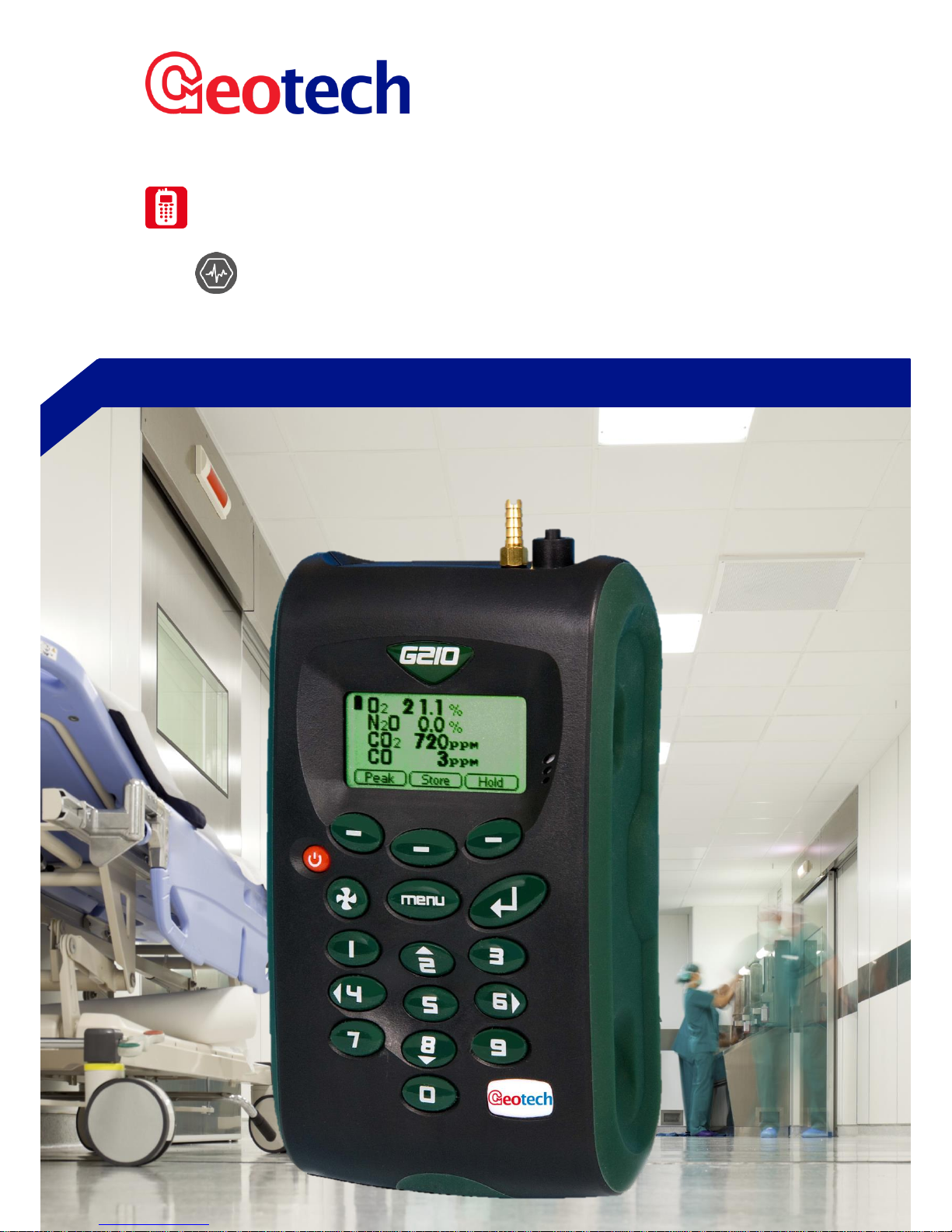
G200 RANGE
G200 AND G210 OPERATING MANUAL
Page 2

Page 2 of 61
Operating Manual
www.geotechuk.com
OMG200N Iss.04
© QED Environmental Systems Ltd.
G 2 00 R A N G E
Table of Contents
Manual Guidelines ................................................................................................................................... 5
Safety Related Information .................................................................................................................. 5
Hyperlinks ............................................................................................................................................ 5
Notes ................................................................................................................................................... 5
Introduction ............................................................................................................................................ 6
The G200 Analyser ............................................................................................................................... 6
The G210 Analyser ............................................................................................................................... 7
Instrument Components - Standard Product ....................................................................................... 8
G200 Range Optional Products and Accessories ..................................................................................... 9
Optional Products ................................................................................................................................ 9
Analyser Data Manager (Optional) ...................................................................................................... 9
Event Log ............................................................................................................................................. 9
Carbon Monoxide Reading (Optional – Enhancement for G210 ONLY) ............................................... 9
Oxygen Reading (Optional – Enhancement for G210 ONLY) ............................................................. 10
Pressure Regulator (Optional - G210 ONLY) ...................................................................................... 10
Soda Lime CO2 Filter .......................................................................................................................... 10
Assembly and connection .............................................................................................................. 11
Instrument Accessory Products ......................................................................................................... 12
Instrument Features .............................................................................................................................. 13
Physical Characteristics of the Instrument Panel ............................................................................... 13
Panel Key Functions ........................................................................................................................... 14
Instrument Connection Points ........................................................................................................... 15
General Operational Instructions .......................................................................................................... 16
Switching the Instrument On ............................................................................................................. 16
Switching the Instrument Off ............................................................................................................. 16
Entering Data ..................................................................................................................................... 16
Numeric Data ................................................................................................................................. 16
Alpha-numeric Data ....................................................................................................................... 17
Instrument Status Icons ..................................................................................................................... 17
Changing Between Parameters.......................................................................................................... 18
Memory ............................................................................................................................................. 18
Storage ............................................................................................................................................... 18
Warning and Error Codes................................................................................................................... 18
Page 3

Page 3 of 61
Operating Manual
www.geotechuk.com
OMG200N Iss.04
© QED Environmental Systems Ltd.
G 2 00 R A N G E
Battery/Charging................................................................................................................................ 18
Instrument Main Read Screen ........................................................................................................... 19
Soft-Keys ........................................................................................................................................ 19
Alternative Reading Methods ............................................................................................................ 19
Peak Reading .................................................................................................................................. 19
Store Reading ................................................................................................................................. 20
Hold Reading .................................................................................................................................. 20
Logged Reading: ............................................................................................................................. 20
Enter ID Codes ................................................................................................................................... 20
Soft-Keys ........................................................................................................................................ 21
Main Menu ........................................................................................................................................ 21
Information .................................................................................................................................... 22
Utilities ........................................................................................................................................... 22
Calibration ...................................................................................................................................... 28
View Data ....................................................................................................................................... 28
Diagnostics ..................................................................................................................................... 30
Monitor (G200 ONLY)..................................................................................................................... 30
Taking Readings ..................................................................................................................................... 35
Preliminary Checks - Best Practice ..................................................................................................... 35
G200 Gas Measurement Process – Best Practice .............................................................................. 36
G210 Gas Measurement Process – Best Practice .............................................................................. 37
Calibration ............................................................................................................................................. 39
User Calibration ................................................................................................................................. 39
Calibration Gases ............................................................................................................................... 39
Calibration Set-up .............................................................................................................................. 39
Calibration Equipment ....................................................................................................................... 40
Calibration Method ............................................................................................................................ 41
Zero Calibration.............................................................................................................................. 41
Span Channels ................................................................................................................................ 42
Last Field Calibration .......................................................................................................................... 42
Calibration Record ............................................................................................................................. 42
Recommended Gases for Calibration ................................................................................................ 43
G200 Range Calibration – Best Practice ............................................................................................. 44
Problem Solving ..................................................................................................................................... 45
Page 4

Page 4 of 61
Operating Manual
www.geotechuk.com
OMG200N Iss.04
© QED Environmental Systems Ltd.
G 2 00 R A N G E
Warnings and Errors .......................................................................................................................... 45
Under and Over Range Codes ........................................................................................................ 45
Self-test Warning Messages............................................................................................................... 46
User Calibration Trouble Shooting ..................................................................................................... 48
User Calibration Explained: ............................................................................................................ 48
Cross-Gas Effects ............................................................................................................................... 50
CO2 Cell .......................................................................................................................................... 50
O2 Cell ............................................................................................................................................ 50
N2O Cell .......................................................................................................................................... 50
CO Cell ............................................................................................................................................ 50
Hardware Reset ................................................................................................................................. 50
Service ................................................................................................................................................... 52
User Serviceable Parts ....................................................................................................................... 52
Cleaning ............................................................................................................................................. 52
Warranty Policy ..................................................................................................................................... 53
Event Log ............................................................................................................................................... 55
WEEE Compliance ................................................................................................................................. 56
EU Declaration of Conformity................................................................................................................ 57
Glossary of Terms .................................................................................................................................. 58
Page 5
Page 5 of 61
Operating Manual
www.geotechuk.com
OMG200N Iss.04
© QED Environmental Systems Ltd.
G 2 00 R A N G E
MANUAL GUIDELINES
Safety Related Information
Information in this manual that may affect the safety of users and others will be in a box
identical to this one.
Failure to follow this information may result in physical injury which in some cases could be fatal.
Hyperlinks
Hyperlinks to other sections of this manual, websites or email addresses are in the following format:
www.geotechuk.com
Notes
Important/useful information and instructions are shown clearly throughout the manual in a note
format.
For example:
Note: For further information please contact Technical Support at QED on +44(0)333 800 0088 or
email [email protected].
Page 6
Page 6 of 61
Operating Manual
www.geotechuk.com
OMG200N Iss.04
© QED Environmental Systems Ltd.
G 2 00 R A N G E
INTRODUCTION
This manual explains how to use the instrument model types listed below:
G200 N20 0-1,000ppm (plus 10,000 range low resolution)
G210 N20 0-100%+CO2 0-2,000ppm+O2 0-100%+CO 0-500ppm
Both units have been developed to incorporate the latest technology and specification requirements,
which provide the user with a fast, simple-to-use and accurate piece of monitoring instrumentation.
Note: These instruments are sensitive pieces of scientific equipment, and should be treated as
such.
If the equipment is used in a manner not specified by the manufacturer, the protection
provided by the equipment may be impaired.
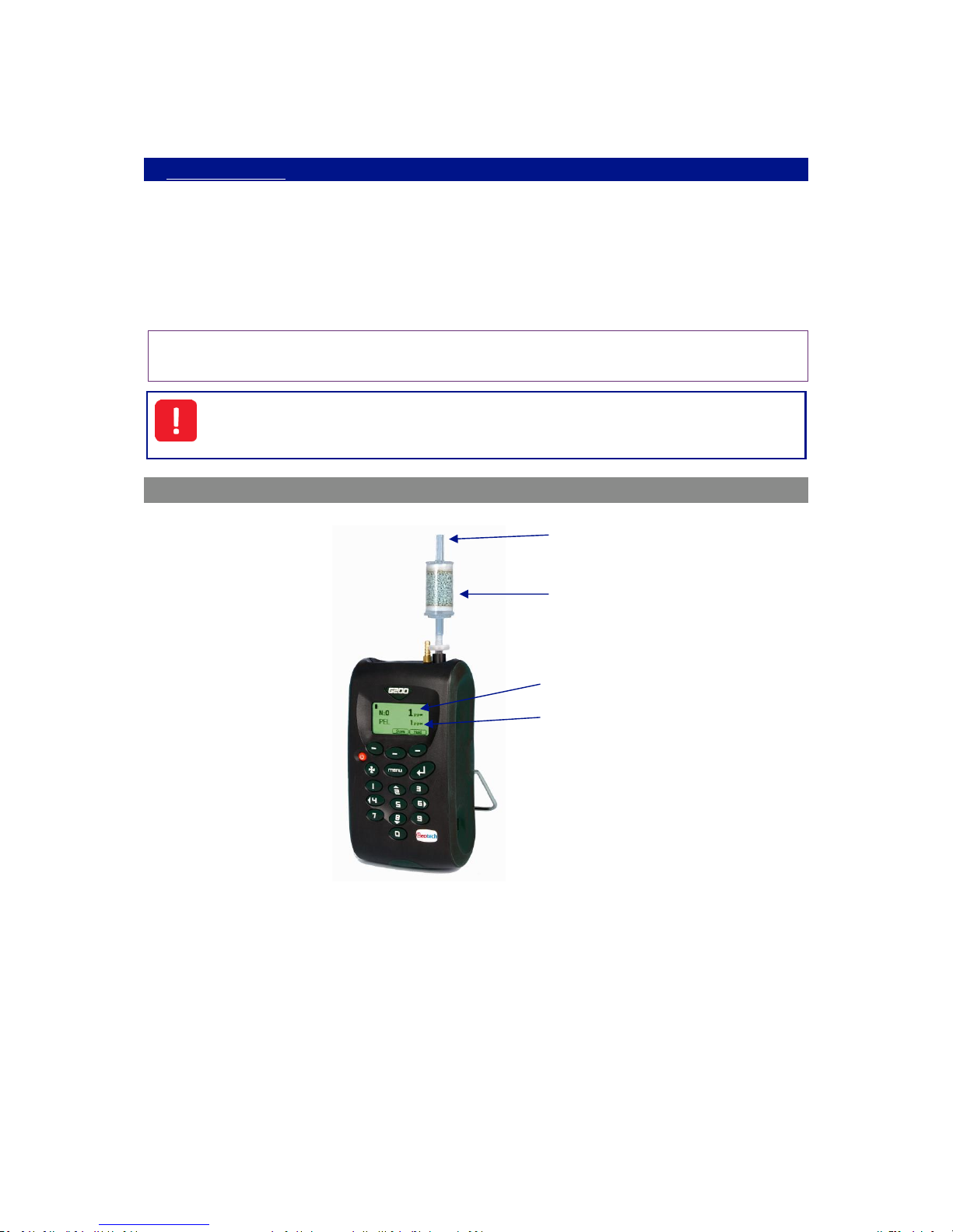
The G200 Analyser
The G200 analyser is specifically designed to safety check background zone levels of N2O (01,000ppm) in medical applications. This instrument measures the long term exposure to N2O gas
along with the TWA (time weighted average), leak detection for N2O storage. It is a dual purpose
background analyser or personal analyser and is highly portable.
The G200 analyser has the following features:
O2, N20 0-1,000ppm
Data storage for 1,000 readings and download
Inlet
Soda Lime
CO2 Filter
Current
Value
TWA Value
Page 7
Page 7 of 61
Operating Manual
www.geotechuk.com
OMG200N Iss.04
© QED Environmental Systems Ltd.
G 2 00 R A N G E
EH40 occupational exposure limits calculated (TWA) – applicable to the UK only
Leak detection
User settable alarms
Data download for graphing and reporting
Four modes of operation: personal safety - TWA 8 hour read back; room monitor –
background levels, user defined times; leak mode – 1-10,000ppm fast response; and standard
measuring.
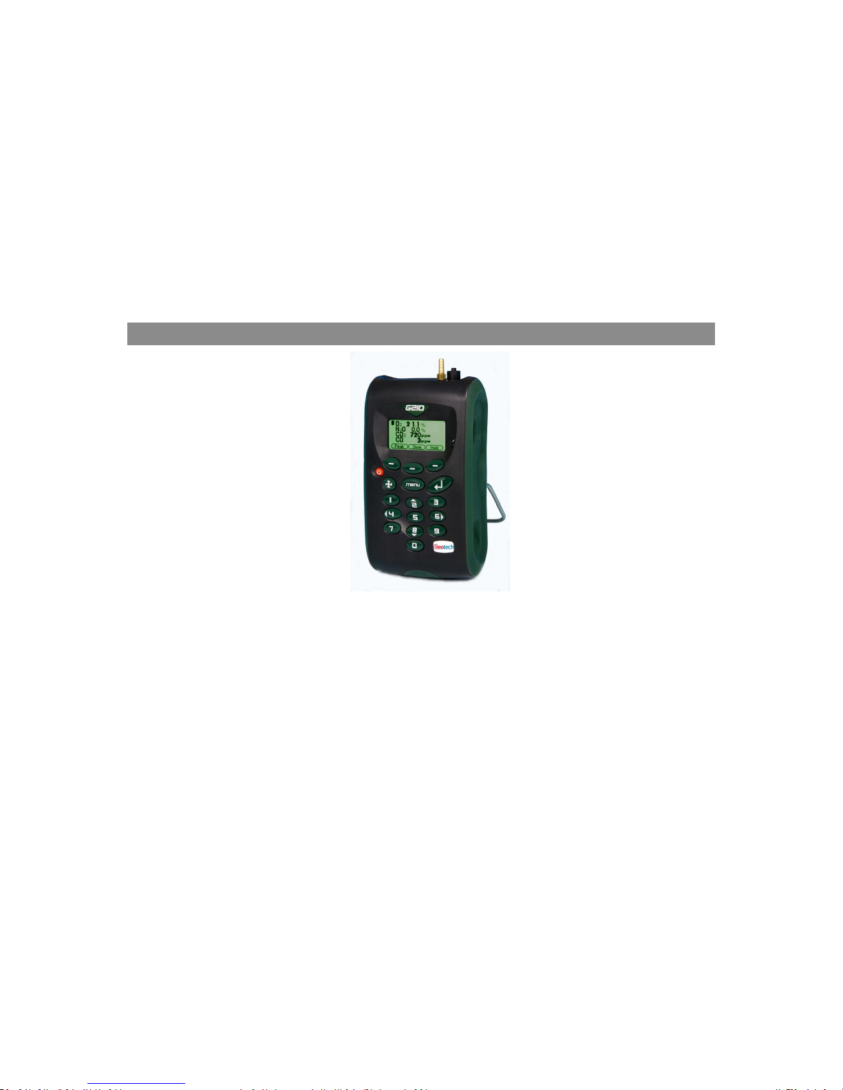
The G210 Analyser
The G210 analyser is specifically designed for highly accurate measurement and verification of the
quality of piped N2O and O2 gases in hospitals. This instrument enables up to four gases to be
measured, easy user calibration, quick verification of gas quality, user maintained site and sample
point IDs for monitoring as well as identification of contaminants CO and CO2.
The analyser has the following features:
N2O 0-100%
O2 0-100% (optional)
CO 0-500ppm (optional)
CO2 0-2,000ppm
Data storage with site and ID input
Data download for graphing and reporting
Page 8
Page 8 of 61
Operating Manual
www.geotechuk.com
OMG200N Iss.04
© QED Environmental Systems Ltd.
G 2 00 R A N G E
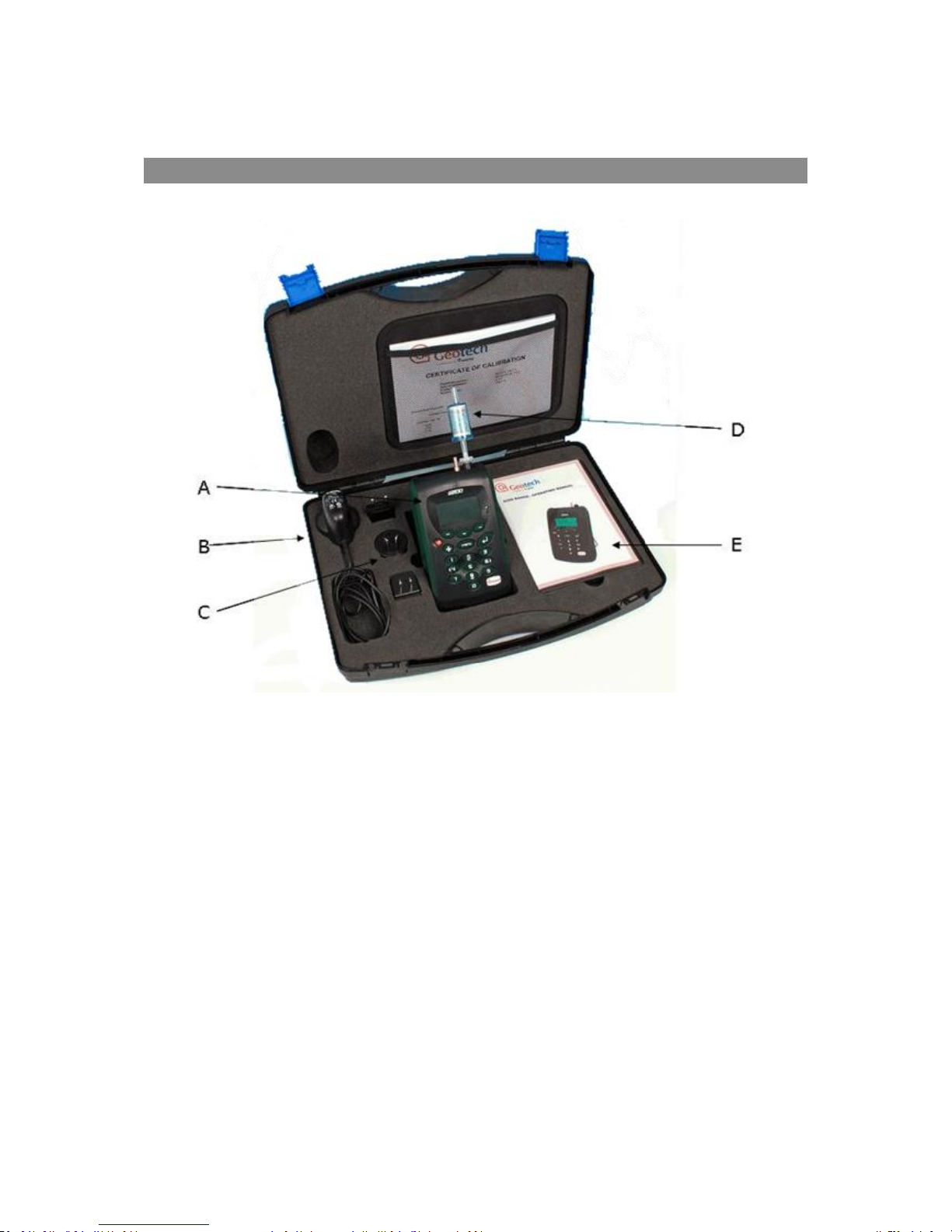
Instrument Components - Standard Product
Reference:
A)
Analyser
B)
Mains Battery Charger
C)
Mains Battery Charger Adaptors:
Europe
US
Australia
D)
Soda Lime CO2 Filter (G200 Only)
E)
Operating Manual
Page 9
Page 9 of 61
Operating Manual
www.geotechuk.com
OMG200N Iss.04
© QED Environmental Systems Ltd.
G 2 00 R A N G E
G200 RANGE OPTIONAL PRODUCTS AND ACCESSORIES
Optional Products
The G200 analyser range has a number of optional products for purchase which enhance the usability
and enable further analysis of data and reading information.
Note: For more information on the features listed in this section please contact Sales at QED on
+44(0)333 800 0088 or email [email protected].
Analyser Data Manager (Optional)
Analyser Data Manager software application enables the operator to maximise the operation of the
analyser by providing the ability to:
Obtain instrument status.
View the instrument readings and event log data.
Download and store readings for further analysis.
Graph downloaded instrument readings.
View, import and export the instrument configuration.
Update the instrument’s firmware.
Copy data from the G200 Client into other packages such as MS Excel.
Email data directly from the application.
Configure remote access to a central database.
Print graph and tabular data.
Event Log
The G200 range of instruments incorporates the facility to log significant events via the ‘Event Log’.
This can be used as an aid to monitoring the use of the instrument. It can also be used as a diagnostic
tool if there is a problem with the instrument.
The event log can only be viewed via the optional Analyser Data Manager software. It cannot be
viewed on the analyser screen. Applicable events are stored in the event log automatically. No user
intervention is required.
The event log can hold approximately 270 events. If the log becomes full then it begins to overwrite
the older events. This can be identified by the index field which starts from event number 1. The log
is cleared when the instrument is reset.
Note: Please refer to section Event Log of this operating manual for further information.
Carbon Monoxide Reading (Optional – Enhancement for G210 ONLY)
The G210 instrument has the optional facility to use an internal CO cell (specified at the time of
manufacture or upon request at service interval). This allows the instrument to read and display
carbon monoxide readings along with N2O.
Page 10
Page 10 of 61
Operating Manual
www.geotechuk.com
OMG200N Iss.04
© QED Environmental Systems Ltd.
G 2 00 R A N G E
Oxygen Reading (Optional – Enhancement for G210 ONLY)
The G210 instrument has the optional facility to use an internal oxygen cell (specified at the time of
manufacture or upon request at service interval). This allows the instrument to read and display
oxygen readings along with N2O, CO2, CO.
Pressure Regulator (Optional - G210 ONLY)
A pressure regulator must be used when taking gas readings to restrict the flow into the instrument
when using the G210 analyser. When sampling piped medical gases the pressure of the gas needs to
be reduced before it is passed to the instrument. This reduces the pressure to 100mbar suitable for
the instrument.
Note: Alternative methods of pressure reduction are available and could be used. However, to
avoid irreversible damage to the instrument, please seek guidance from the supplier /
manufacturer before using any other pressure device.
Do NOT use the instrument at full piped pressure (maximum pressure 300mbar).
Soda Lime CO2 Filter
The G200 instrument must only be used with a soda lime CO2 filter attached. The filter removes CO2 if
present when a reading is taken.
This filter should always be fitted when using a G200 instrument as any CO2 will cross-contaminate
the N2O reading. For further information please refer to section Cross-Gas Effects.
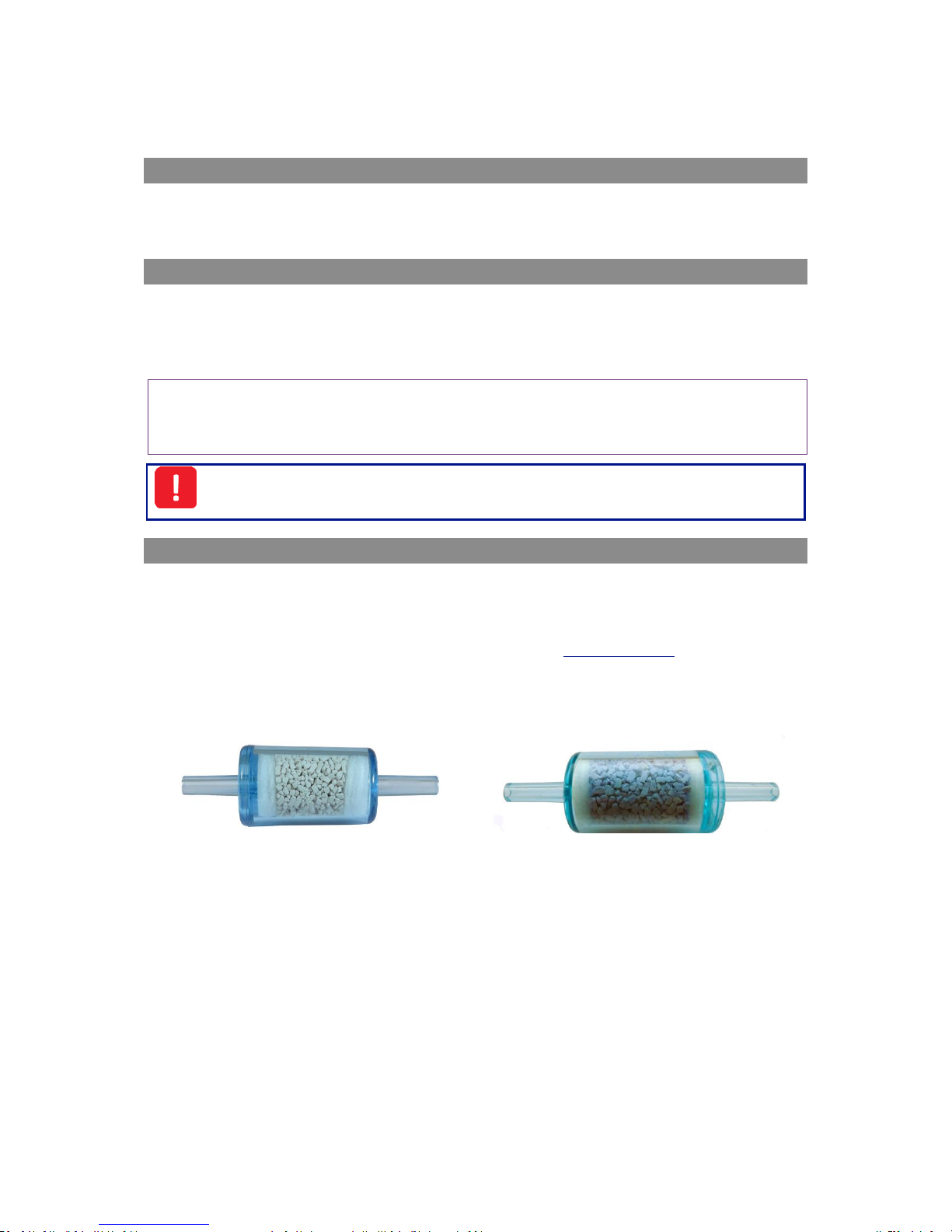
The life of the filter will vary depending on usage. The crystals change colour from pale green-blue to
white-grey. The filter element should be discarded when a significant percentage of the crystals start
to turn a white-grey colour see below:-
Figure 1 - New filter (pale green/blue)
Figure 2 - Used filter (white/grey)
Page 11
Page 11 of 61
Operating Manual
www.geotechuk.com
OMG200N Iss.04
© QED Environmental Systems Ltd.
G 2 00 R A N G E
Assembly and connection
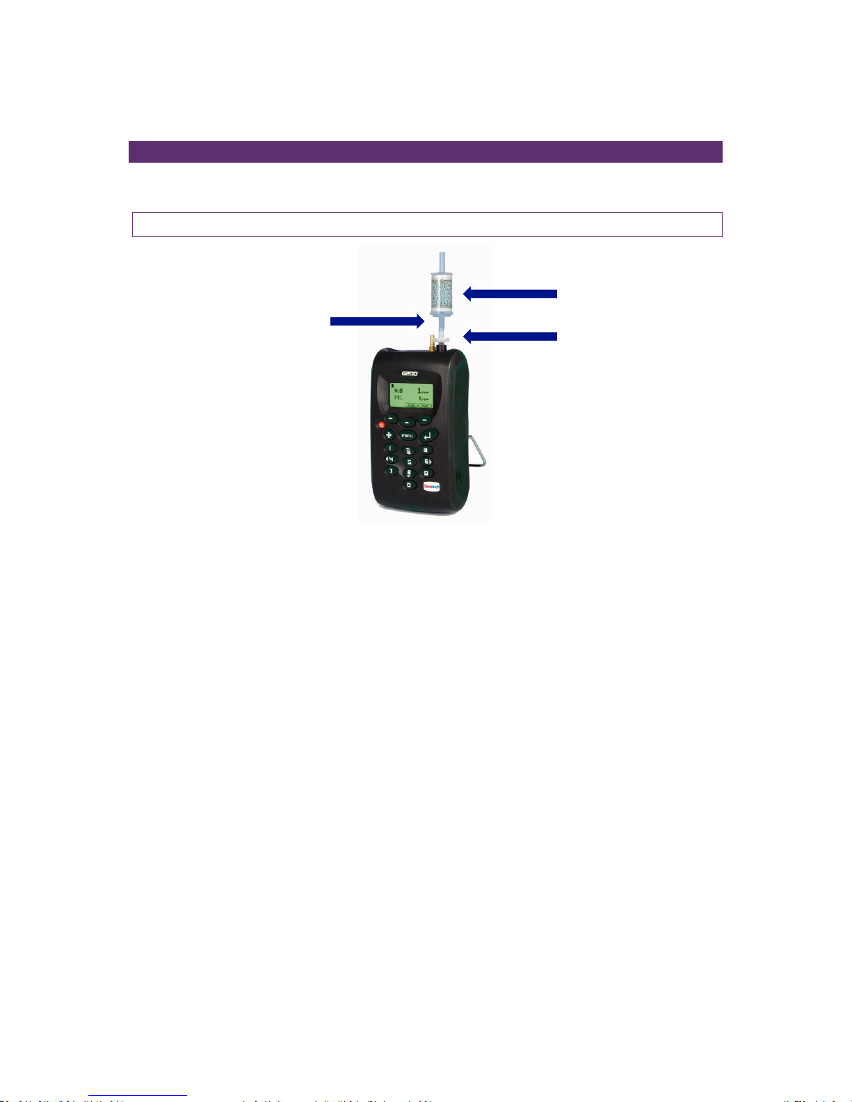
The filters are supplied in a sealed storage bag to improve their shelf life. The parts supplied should be
assembled as per the diagram shown.
Note: A soda lime CO2 filter can also be used to zero other G Range instruments.
Soda Lime Filter
Tubing
PTFE Filter
Page 12
Page 12 of 61
Operating Manual
www.geotechuk.com
OMG200N Iss.04
© QED Environmental Systems Ltd.
G 2 00 R A N G E
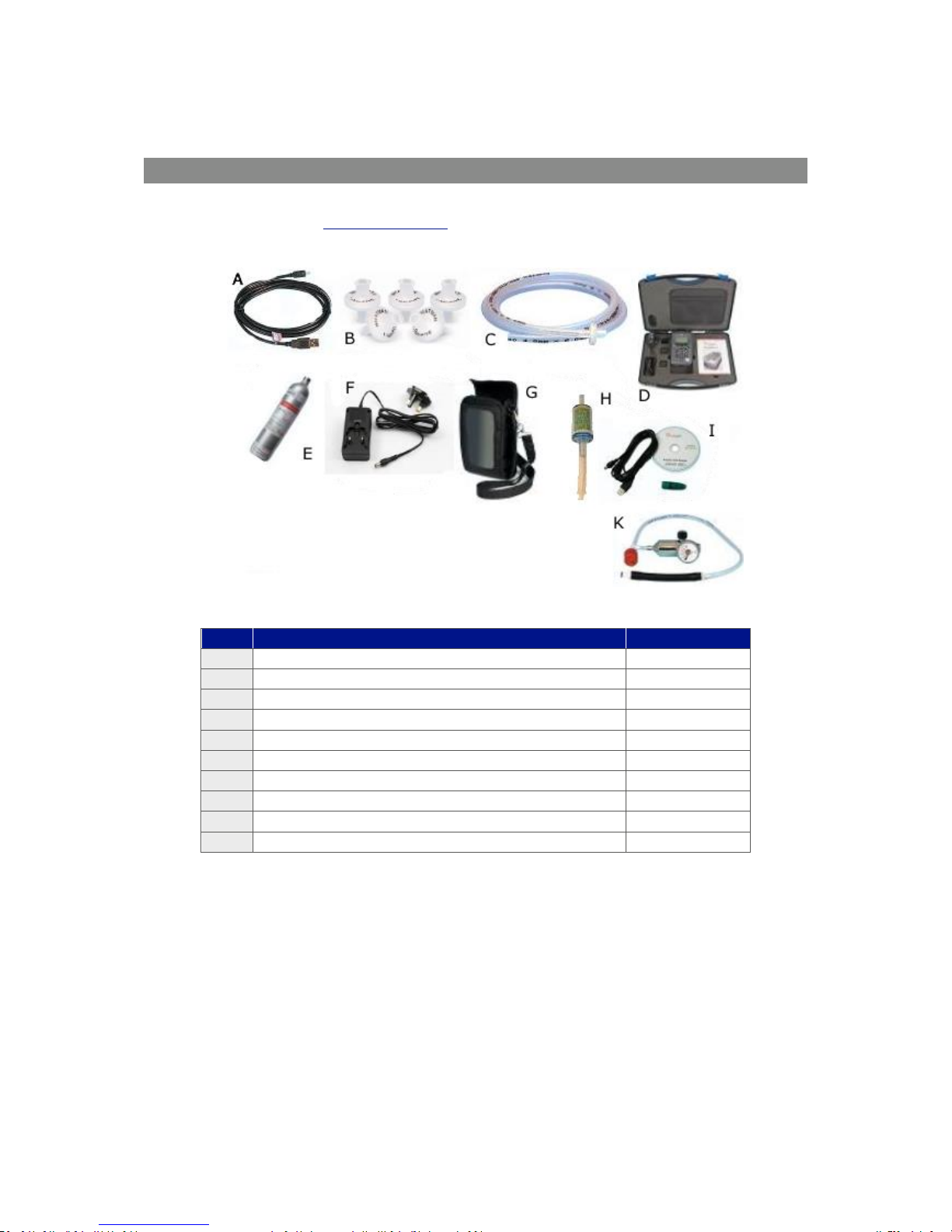
Instrument Accessory Products
Optional accessory and replacement parts may be purchased for the G200 range from QED direct.
Please refer to the website www.qedenv.co.uk for further details on pricing and how to order.
Ref
Description
Part Number
A
USB Lead
USBLEAD2
B
Spare Sample Filters (pack of 5)
068296/S
C
Sample Tube Kit
G1.6
D
Hard Carry Case
050227
E
Spare Calibration Gas (Various gas options available)
CDA7.6
F
Mains Charger including Worldwide Adaptors
073024
G
Soft Carry Case
G1.11
H
Soda Lime Filter Kit
G1.10
I
Analyser Data Manager Software
G1.4
K
Regulator and Tubing for Calibration Gas
G1.1
Page 13
Page 13 of 61
Operating Manual
www.geotechuk.com
OMG200N Iss.04
© QED Environmental Systems Ltd.
G 2 00 R A N G E
INSTRUMENT FEATURES
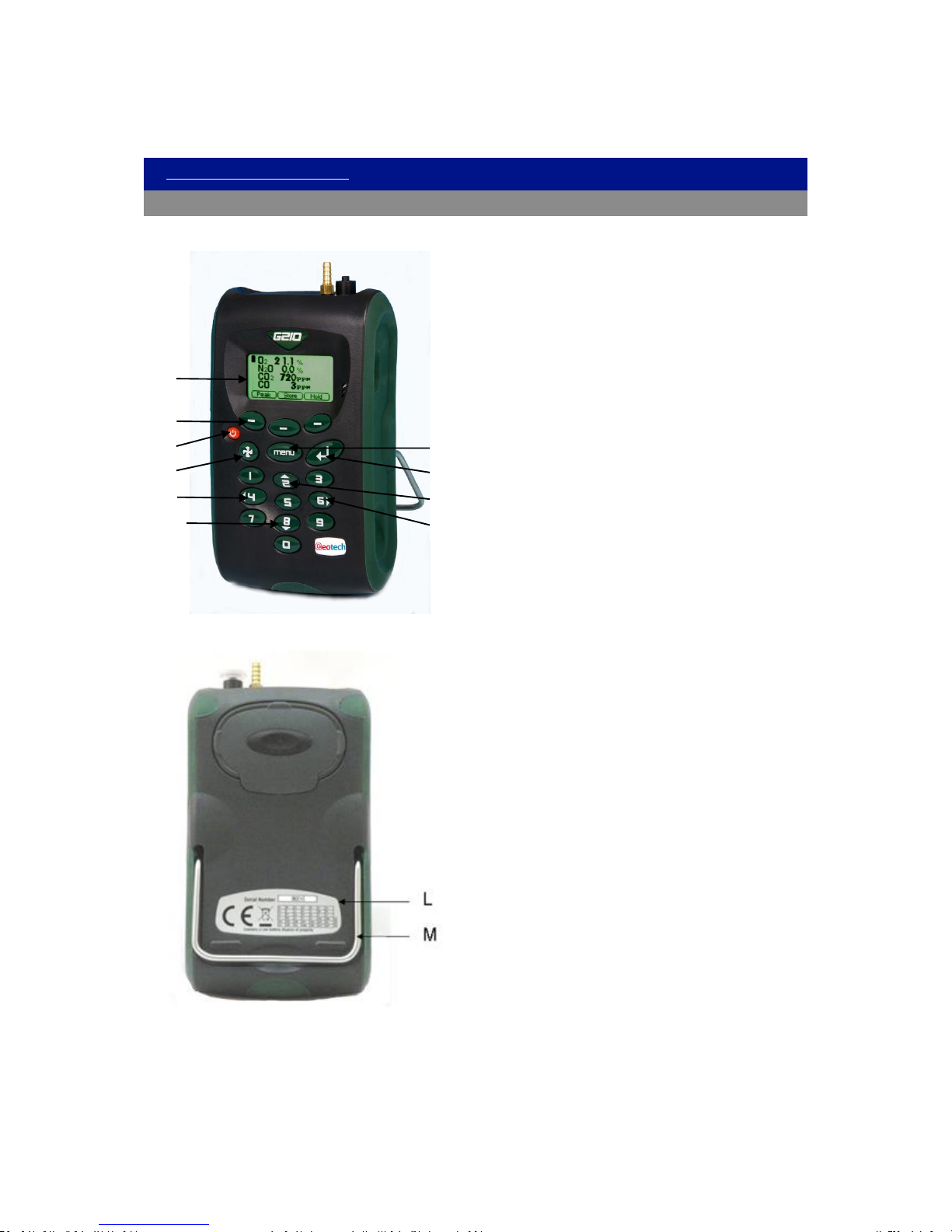
Physical Characteristics of the Instrument Panel
Front View:
Reference:
A) Main Read Screen
B) Soft keys
C) On/Off key
D) Pump key
E) Key 4 – scroll left
F) Key 8 – scroll down
G) Menu key
H) Enter key
I) Key 2 – scroll up
J) Key 6 – scroll right
Back View:
Reference:
L) Serial number
M) Instrument stand
A B C
D E F G H I J
Page 14

Page 14 of 61
Operating Manual
www.geotechuk.com
OMG200N Iss.04
© QED Environmental Systems Ltd.
G 2 00 R A N G E
Panel Key Functions
Key
Description
Function
A
Main Read Screen
Start and end screen when using the instrument.
B Soft Keys
The function of the three ‘soft-keys’ on the front of the
instrument panel are determined by menu options
taken. Functions vary from screen to screen.
C
On/Off Key
Press the ‘On/Off’ key briefly to switch the instrument
on and off.
D
Pump Key
Press the ‘Pump’ key to start or stop the pump.
E Scroll Left Key
Also ‘Key 4’. Enables the operator to scroll left to
display more information.
F
Scroll Down Key
Also ‘Key 8’. Enables the operator to scroll down to
display more information.
G
Menu Key
Press the ‘Menu’ key to go to the ‘Main’ menu. Enables
the operator to pre-set values and settings. Select
options from the ‘Main’ menu to also view data and
readings stored or held.
H
Enter Key
The ‘Enter’ key accepts/confirms choices made by the
operator to various functions and operations. Also,
required to confirm numeric data entry.
I
Scroll Up Key
Also ‘Key 2’. Press scroll up to view further information
on the instrument read screen.
J
Scroll Right Key
Also ‘Key 6’. Press scroll right to view further
information on the instrument read screen.
L
Serial Number
Unique Identification for the instrument. Verification of
the serial number will be required if Technical Support
assistance is needed.
M
Instrument Stand
Instrument stand.
Page 15
Page 15 of 61
Operating Manual
www.geotechuk.com
OMG200N Iss.04
© QED Environmental Systems Ltd.
G 2 00 R A N G E
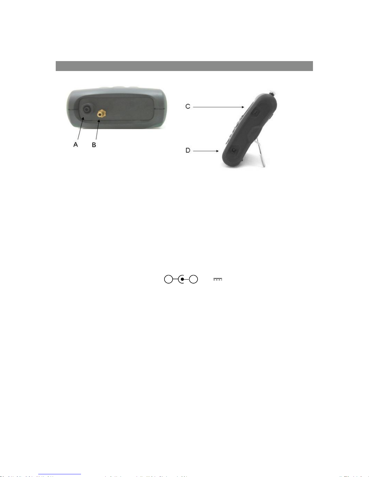
Instrument Connection Points
Top View:
Side View:
Key
Description
Function
A
Gas Inlet
Gas inlet point used to attach the sample tube and filter
in order to take the gas reading
B
Gas Outlet
Gas outlet port used to exhaust the gas
C
USB Port
Used to connect the analyser to a PC via a USB cable to
download data
D
Charger Port
Used to attach the main charger to the analyser for
charging
5V ± 0.5V(max 1000mA)
+-
5V ± 0.5V(max 1000mA)
+- +-
Page 16
Page 16 of 61
Operating Manual
www.geotechuk.com
OMG200N Iss.04
© QED Environmental Systems Ltd.
G 2 00 R A N G E
GENERAL OPERATIONAL INSTRUCTIONS
Note: Fully charge the unit before use when the instrument is first received or if the instrument
has been in storage for six months or more.
Switching the Instrument On
To switch on the instrument, press the ‘On/Off’ key briefly. There will be a short beep and a
slight pause followed by the Geotech logo.
The power on self-test will commence.
Assuming there are no warnings to display the instrument will continue to the ‘Main Read
Screen’.
Switching the Instrument Off
Purge with fresh air. Run the pump for approximately 30 seconds or until the readings have
returned to normal levels.
Note: Before the instrument is switched off a clean air purge should be performed. This ensures
that the instrument is free from gas and ready for the next measurement. This final purge is
especially important for the oxygen sensor as it may degrade if stored when contaminated with
gas.
To switch off the instrument, press the ‘On/Off’ key briefly.
Note: If the ‘Auto Off’ utilities setting is set to ‘Yes’, the analyser will switch off automatically
after ten minutes if not in use.
Entering Data
During normal operation the user may be prompted to enter data or information via the keypad, i.e.
entering an ID code or setting an alarm level.
When entering data into the instrument all fields are fixed format and are populated from the right.
Numeric Data
To enter a new time 09:25:00 the user would type in 092500 using the numeric keypad in the
following sequence:-
* __:__:_0
* __:__:09
* __:_0:92
* __:09:25
* _0:92:50
* 09:25:00
Press the ‘Enter’ key to confirm/accept data keyed.
Page 17
Page 17 of 61
Operating Manual
www.geotechuk.com
OMG200N Iss.04
© QED Environmental Systems Ltd.
G 2 00 R A N G E
Any mistakes can be corrected using the soft-key ‘Delete’ which will delete the last digit typed.
Alternatively, the sequence can be retyped before the ‘Enter’ key is pressed and the existing numbers
will be pushed off the screen.
Alpha-numeric Data
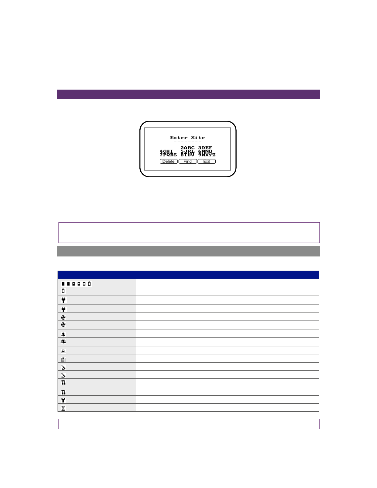
When entering site IDs, alpha-numeric codes may be specified. To enter characters select either ‘1Site’ or ‘2-ID’ followed by the ‘Menu’ key and the following screen is displayed:
Screen 1 – Enter site
The operator can choose upper and lowercase characters. Press the ‘Menu’ key again to choose
lowercase characters. Use the numeric keypad on the instrument to select the appropriate letter, i.e.
to select A ‘Key 2’, to select B ‘Key 2’ twice (just like on a mobile phone).
Note: The instrument will not allow invalid data to be entered; this should be deleted and reentered.
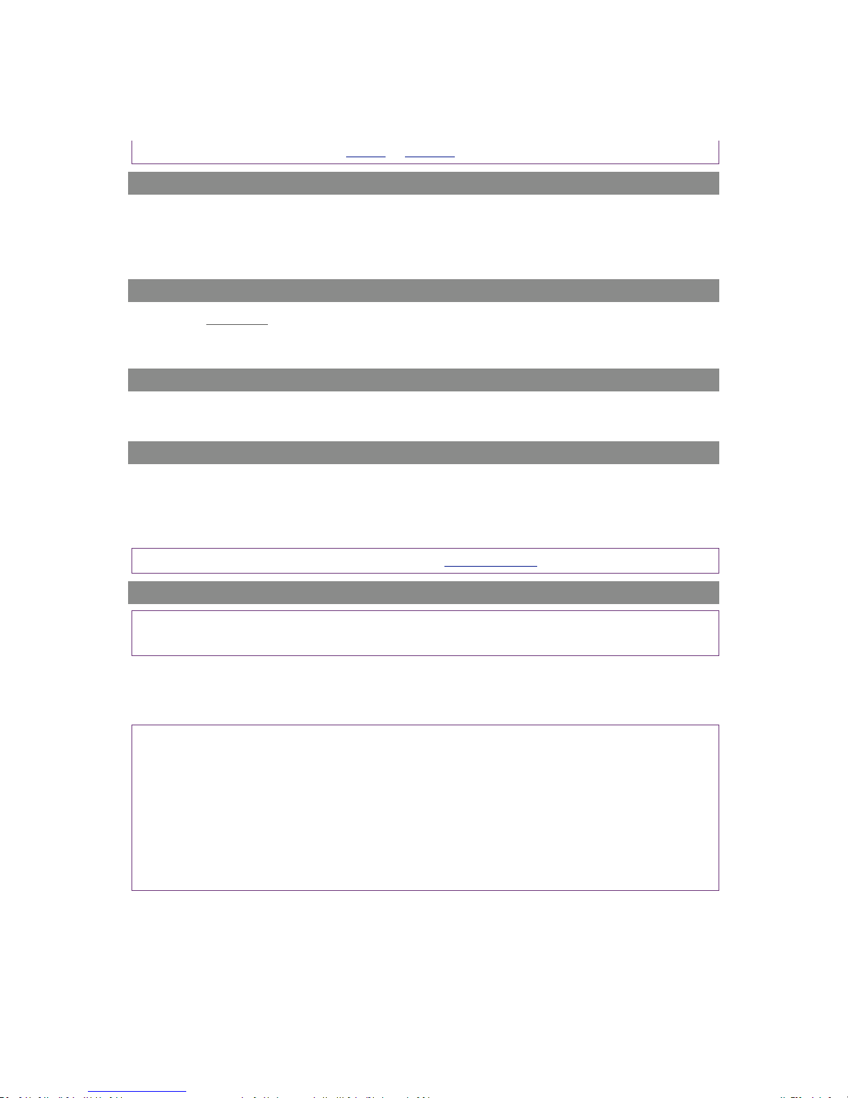
Instrument Status Icons
The following icons may be displayed on the instrument read screens:
Icon
Description
Battery charge state
(flashing)
< 1 hour remaining
(flashing)
Battery charging
Charged
Pump running
(flashing)
Pump stalled (Backlight turns red)
Alarm set
(flashing)
Alarm active (Backlight turns red)
USB connected to PC (flickers when transferring data)
Logging mode active (flashes when memory nearly full)
Temperature probe(s) connected
Humidity probe connected
(flashing)
Service due (every 12 months)
Service overdue
Fault/repair
Waiting
Note: A red backlight is displayed if the pump is stalled or the alarm is activated. For further
Page 18
Page 18 of 61
Operating Manual
www.geotechuk.com
OMG200N Iss.04
© QED Environmental Systems Ltd.
G 2 00 R A N G E
information, please refer to section Alarms or Flow Fail.
Changing Between Parameters
By default, the instrument displays the ‘Main Read Screen’ (for gas measurement). The instrument
will return to this screen after power on or when returning from the menus. The ‘Scroll’ keys can be
used to switch to another measurement screen. Continue to press the ‘Scroll’ keys to return to the
‘Main Read Screen’.
Memory
The memory should not be used as a permanent storage medium and any important data should be
transferred to a more permanent storage medium as soon as possible. The instrument should not be
stored for prolonged periods with valuable data in its memory.
Storage
When not in use the instrument should be kept in a clean, dry and warm environment, such as an
office. It should be stored flat with the stand folded away which helps prolong the life of the O2 cell.
Warning and Error Codes
When switched on the instrument will perform a predetermined self-test sequence taking
approximately ten seconds. During this time many of the instrument’s working parameters and
settings are checked. If any operational parameters are out of specification or if the pre-programmed
recommended calibration/service date has passed, errors or warnings may be displayed.
Note: For further information please refer to section Problem Solving.
Battery/Charging
Note: Fully charge the unit before use when the instrument is first received or if the instrument has
been in storage for six months or more.
The battery used in the instrument is a 2.6 Ah Lithium-Ion cell. The instrument must be charged using
the power supply supplied with your instrument. The power supply supplied is intended for indoor
use only. Please ensure adequate ventilation whilst charging.
Note: The instrument cannot be powered or charged via the USB connector.
Note: When plugged into the power supply the instrument will power on and display charging.
When complete the display will change to show that the instrument is charged. To switch the
instrument ON whilst charging or charged is displayed, the operator will need to press and hold the
power key briefly.
Note: Once the instrument is fully charged, the power supply should be disconnected from the
instrument.
Page 19
Page 19 of 61
Operating Manual
www.geotechuk.com
OMG200N Iss.04
© QED Environmental Systems Ltd.
G 2 00 R A N G E
Instrument: Input: 5Vdc ± 0.5V (max 1000mA)
Power Supply: Input: 100 -240Vac 60/50Hz 120mA
Output: 5Vdc 1000mA (5VA)
Note: A full charge will take approximately 4 hours. Typically, a fully charged battery will last 1012 hours.
When the instrument is already powered on, the operation is slightly different as the battery icon
changes to a flashing plug symbol. This will stop flashing when the charge is complete.
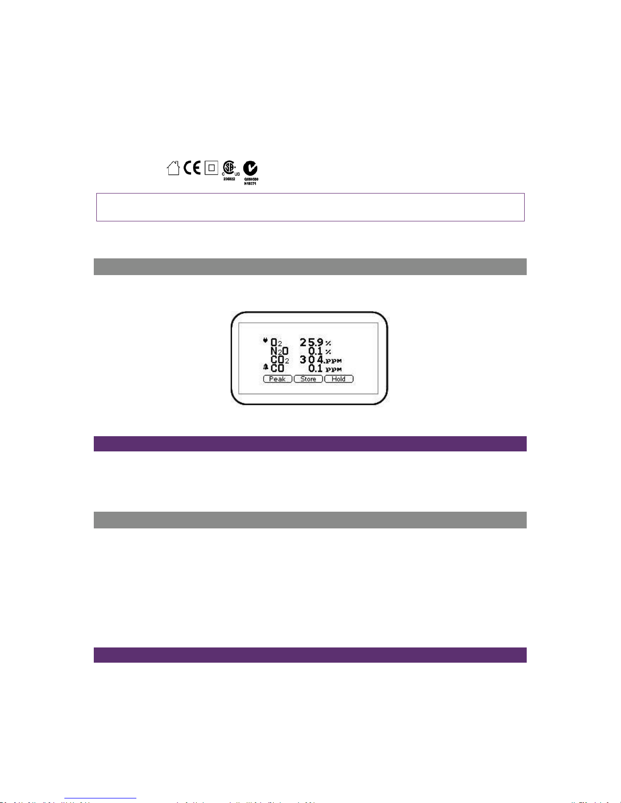
Instrument Main Read Screen
After the analyser has been switched on and the warm-up self-tests completed the analyser will
display the following screen.
Screen 2 - Main readings
Soft-Keys
Peak - Enables the operator to display the peak reading.
Store - Enables the operator to store the reading for viewing/download later.
Hold - Enables the operator to hold the current reading being taken.
Alternative Reading Methods
The G210 has three reading types or methods which each require slightly different operating
procedures:
Peak reading
Store reading
Hold reading
Logged reading
Peak Reading
The operator can toggle the reading mode between normal (current) and peak readings. Whilst in
peak reading mode the instrument will only display peak values for each of the channels. These
values can then be stored by pressing the ‘Store’ key or automatically at the appropriate logging
Page 20
Page 20 of 61
Operating Manual
www.geotechuk.com
OMG200N Iss.04
© QED Environmental Systems Ltd.
G 2 00 R A N G E
interval (if logging is enabled).
The peak value is reset after a reading is stored or by exiting the peak mode using the appropriate
soft-key. The current mode of operation can be identified by the status of the soft-key, either
‘Normal’ or ‘Inverse’, where inverse indicates peak mode is active.
Store Reading
The ‘Store’ reading option allows the operator to store the current reading. Upon selecting this
option the operator is then prompted to enter or select a ‘Site ID’ and ‘Sample Point ID’ to identify the
reading. Select the ‘Accept’ button to confirm the ID choices. For further information please refer to
section Enter ID Codes.
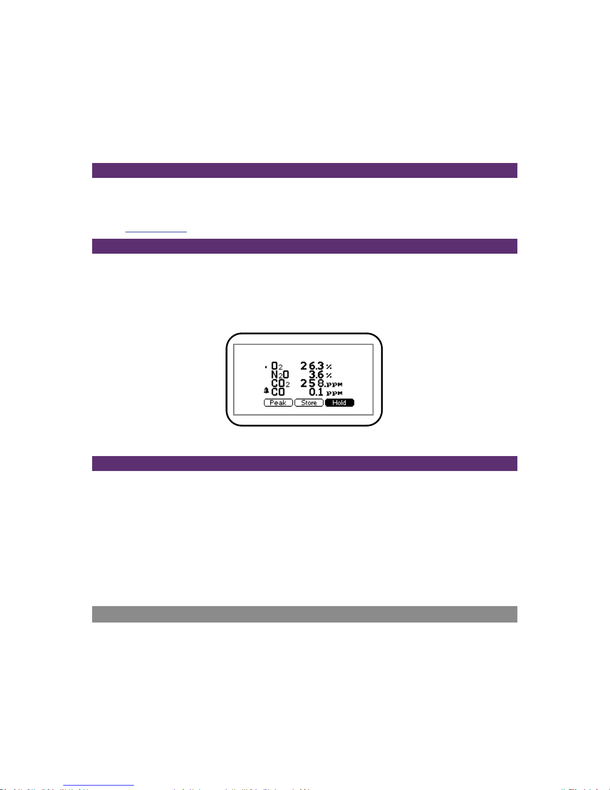
Hold Reading
The ‘Hold’ reading option allows the operator to freeze the currently displayed reading. This allows it
to be manually recorded or moved away from the sample point. Once activated, press the soft-key
‘Hold’ and the readings are fixed until the ‘Hold’ key is pressed again or the reading is stored.
The current mode of operation can be identified by the status of the soft-key which is inversed whilst
in the hold phase.
Screen 3 - Hold reading
Logged Reading:
Logged readings need to be configured and initiated via the ‘Utilities’ menu by pressing ‘Key 6 Logging’. During configuration the user will be asked to supply an ID, reading interval and pump run-
time.
These parameters are used to control the reading frequency in logging mode. Once logging mode is
activated the instrument will automatically record a reading at every interval until stopped by the
operator or the memory becomes full. Logging is also suspended temporarily whilst the user is
accessing the menu options.
Whilst the logging mode is active both the ‘Pump’ and ‘Store’ key will be deactivated; only logged
readings can be stored.
Enter ID Codes
ID codes are either created at the time of selection on the analyser or created using the Analyser Data
Manager software and uploaded to the instrument for selection prior to readings being taken.
The ‘Site’ (top level ID) and ‘ID’ (second level ID) fields refer to the identifier that the operator gives to
a reading set before it is stored. The G200 and G210 allows the operator to enter up to 16 alphanumeric characters which are split into two parts (to help manage the data) called ‘Site’ and ‘ID’ by
Page 21
Page 21 of 61
Operating Manual
www.geotechuk.com
OMG200N Iss.04
© QED Environmental Systems Ltd.
G 2 00 R A N G E
default. These are entered as two sets of eight alpha-numeric identifiers by the operator (i.e. typed
in). For example, the first part called ‘Site’ can be used to store the name of the building i.e. ‘Warwick’
and the second part called ‘ID’ could be used for location or room where the reading was taken, i.e.
‘A&E1’.
It is possible using Analyser Data Manager to change the name of these fields as displayed on the
instrument from ‘Site’ and ‘ID’ to something else up to seven characters, i.e. ‘ward’ and ‘bed’,
depending on the application or typical mode of operation.
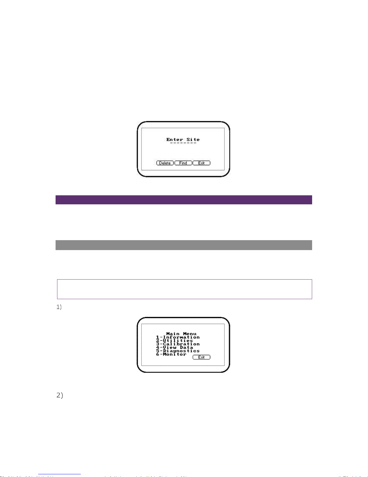
Screen 4 - Enter site ID
Soft-Keys
Delete – Enables the operator to backspace delete digits keyed in the ‘Enter Site’ field.
Find – Enables the operator to search and find pre-stored IDs.
Exit – Enables the operator to exit the ‘Enter Site ID’ screen and return to the ‘Main Read Screen’.
Main Menu
The ‘Main Menu’ enables the operator to select options to set up specific parameters and perform
operational tasks prior to sample readings being taken or to view data and information stored in the
instrument.
Note: Unless otherwise stated the functions and menus are the same for both the G200 and G210
instrument.
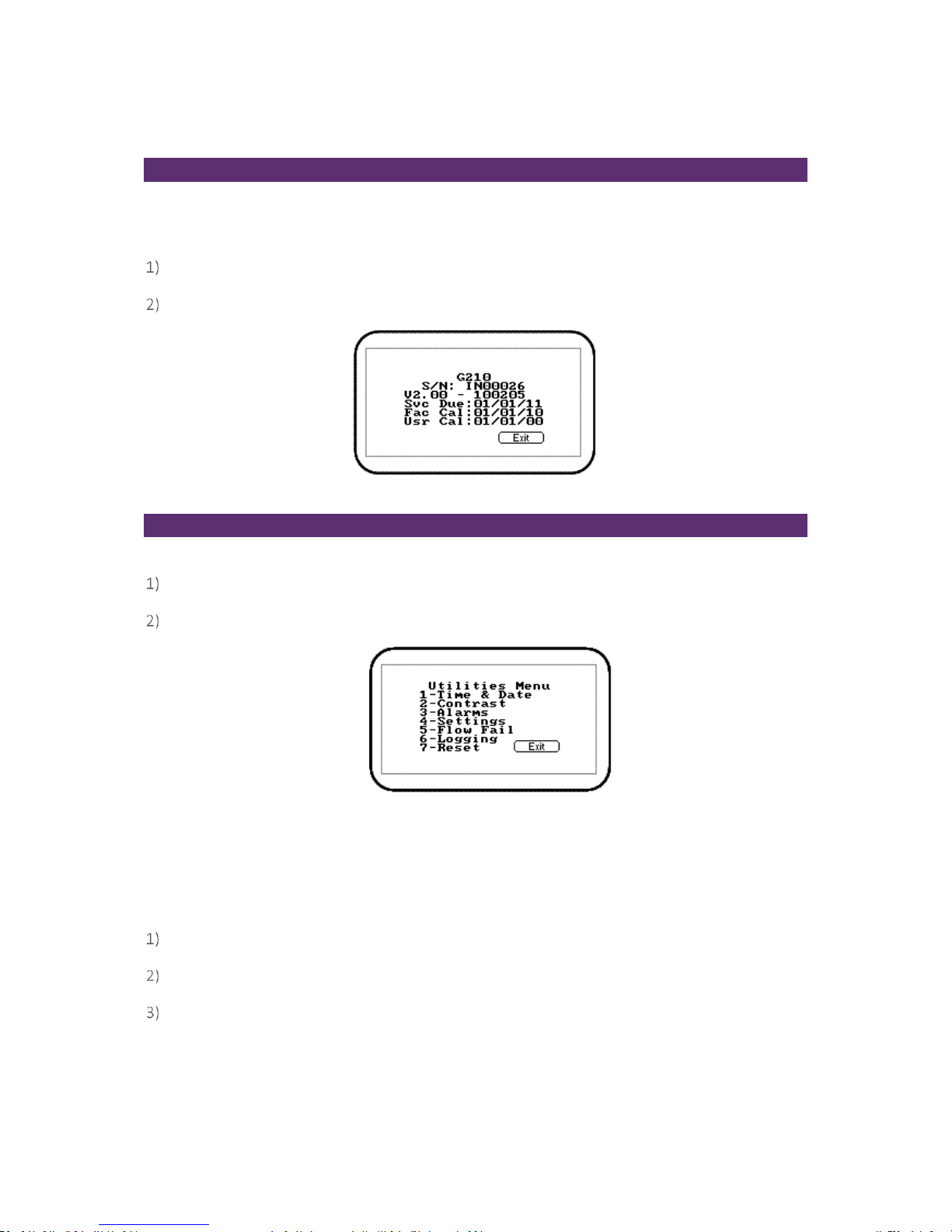
Press the ‘Menu’ key on the front of the instrument panel and the following screen is displayed:
Screen 5 - Main menu
Press the soft-key ‘Exit’ to exit the ‘Main’ menu.
Page 22
Page 22 of 61
Operating Manual
www.geotechuk.com
OMG200N Iss.04
© QED Environmental Systems Ltd.
G 2 00 R A N G E
Information
The ‘Information’ option enables the operator to display information such as instrument type, serial
number, current software version, service due date and the dates of the last factory and user
calibrations.
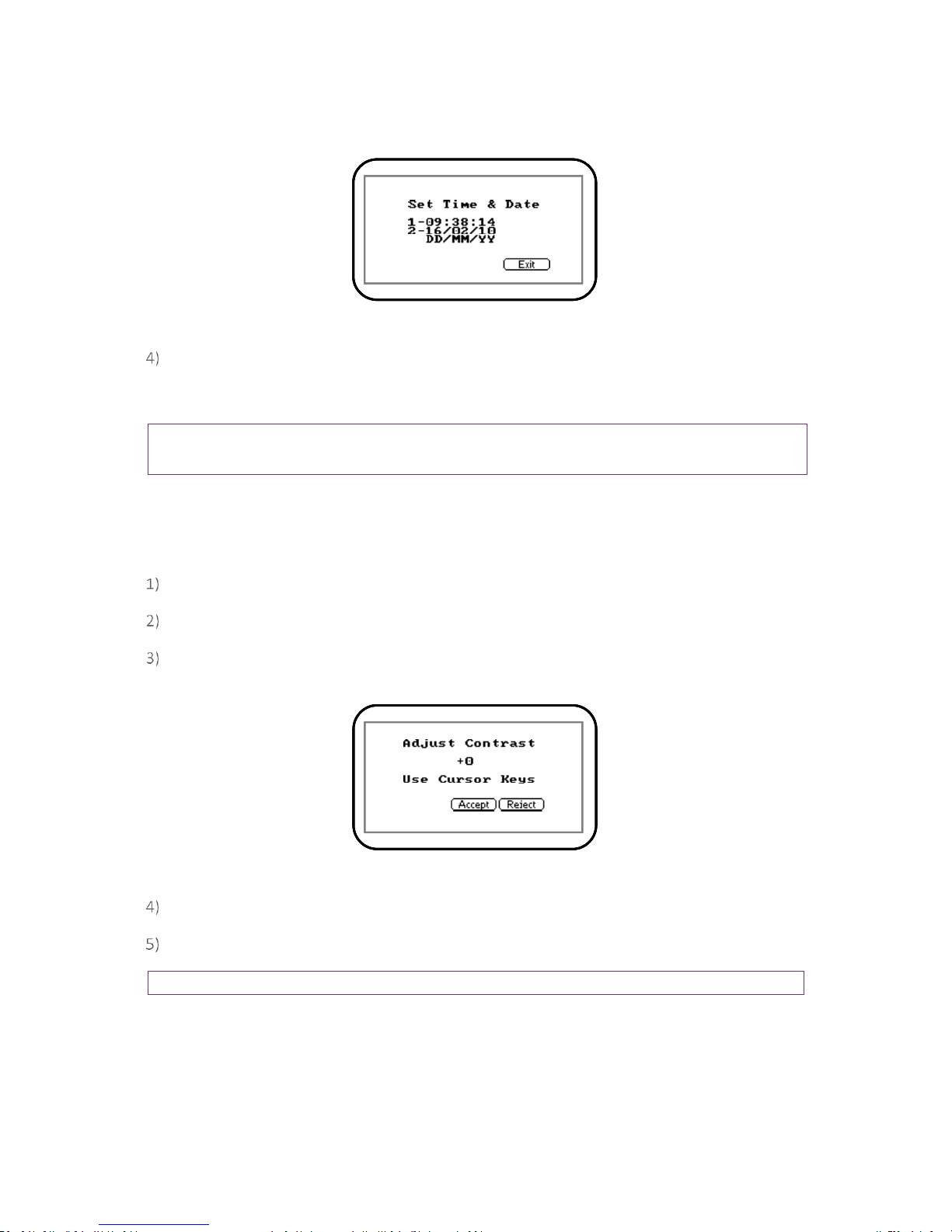
From the ‘Main Read Screen’ press the ‘Menu’ key on the instrument panel.
Press ‘Key 1’ to display general information about the instrument.
Screen 6 - Information
Utilities
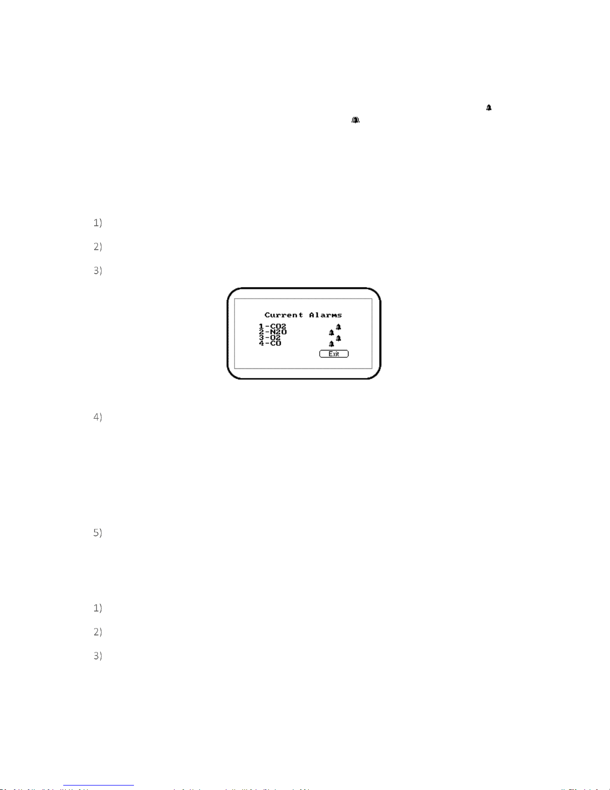
The ‘Utilities’ option enables the operator to configure instrument settings prior to taking readings.
From the ‘Main Read Screen’ press the ‘Menu’ key on the instrument panel.
Press ‘Key 2’ to display the ‘Utilities’ menu and the following screen is displayed:
Screen 7 - G210 utilities menu
Time & Date
The ‘Time & Date’ option enables the operator to check or set the instrument’s internal clock. The
current time/date are appended to every stored reading.
From the ‘Main Read Screen’ press the ‘Menu’ key on the instrument panel.
Press ‘Key 2’ to display the ‘Utilities’ menu.
Press ‘Key 1’ and the ‘Set Time & Date’ menu is displayed:
Page 23
Page 23 of 61
Operating Manual
www.geotechuk.com
OMG200N Iss.04
© QED Environmental Systems Ltd.
G 2 00 R A N G E
Screen 8 - Set time & date
Press ‘Key 1’ to change the time or press ‘Key 2’ to change the date. Type the time or date
using the numeric keypad followed by the ‘Enter’ key. The instrument will not allow invalid
times or dates to be entered.
Note: The clock will need to be manually adjusted to cope with daylight saving changes or changes
when crossing time zones.
Contrast
The ‘Contrast’ option enables the operator to adjust the instrument screen contrast to compensate
for changes in ambient temperature. The default setting is 0.
From the ‘Main Read Screen’ press the ‘Menu’ key on the instrument panel.
Press ‘Key 2’ to display the ‘Utilities’ menu.
Press ‘Key 2’ to select the instrument panel contrast settings and the following screen is
displayed:
Screen 9 - Adjust contrast
Press ‘Key 3 - Scroll Left’ and ‘Key 6 - Scroll Right’ to adjust the value displayed.
Press the soft-key ‘Accept’ or ‘Reject’ accordingly to accept or reject the changes.
Note: The manually set contrast setting is retained when the instrument is switched off.
Alarms
The G200 range of instruments has the facility to set rising or falling alarms for the main gas channels.
The alarms for each channel can be enabled or disabled independently via the ‘Alarms’ menu option.
Page 24
Page 24 of 61
Operating Manual
www.geotechuk.com
OMG200N Iss.04
© QED Environmental Systems Ltd.
G 2 00 R A N G E
Once enabled these alarms become active in the ‘Main Read Screen’; this is indicated by a bell icon.
If an alarm is triggered the screen turns red and a flashing bell icon is displayed. The beeper is
sounded until the gas level has recovered beyond the trigger point.
Rising alarms are triggered when the gas level exceeds the maximum value entered by the
user.
Falling alarms are triggered when the gas level falls below the minimum value entered by the
user.
From the ‘Main Read Screen’ press the ‘Menu’ key on the instrument panel.
Press ‘Key 2’ to display the ‘Utilities’ menu.
Press ‘Key 3’ to select ‘Alarms’ and the following screen is displayed:
Screen 10 - Current Alarms (G210)
Press the appropriate key/option number to maintain the alarm settings. Select from the
following:
1 – Enabled/Disabled: Toggle between disabled and enabled alarm status.
2 – Max: Sets the upper limit alarm setting.
3 – Min: Sets the minimum alarm setting. The default is 0.
Select the option key to modify followed by the soft-key ‘Accept’ or ‘Reject’.
Settings
The ‘Settings’ option enables the operator to maintain information with regards to taking samples and
readings.
From the ‘Main Read Screen’ press the ‘Menu’ key on the instrument panel.
Press ‘Key 2’ to display the ‘Utilities’ menu.
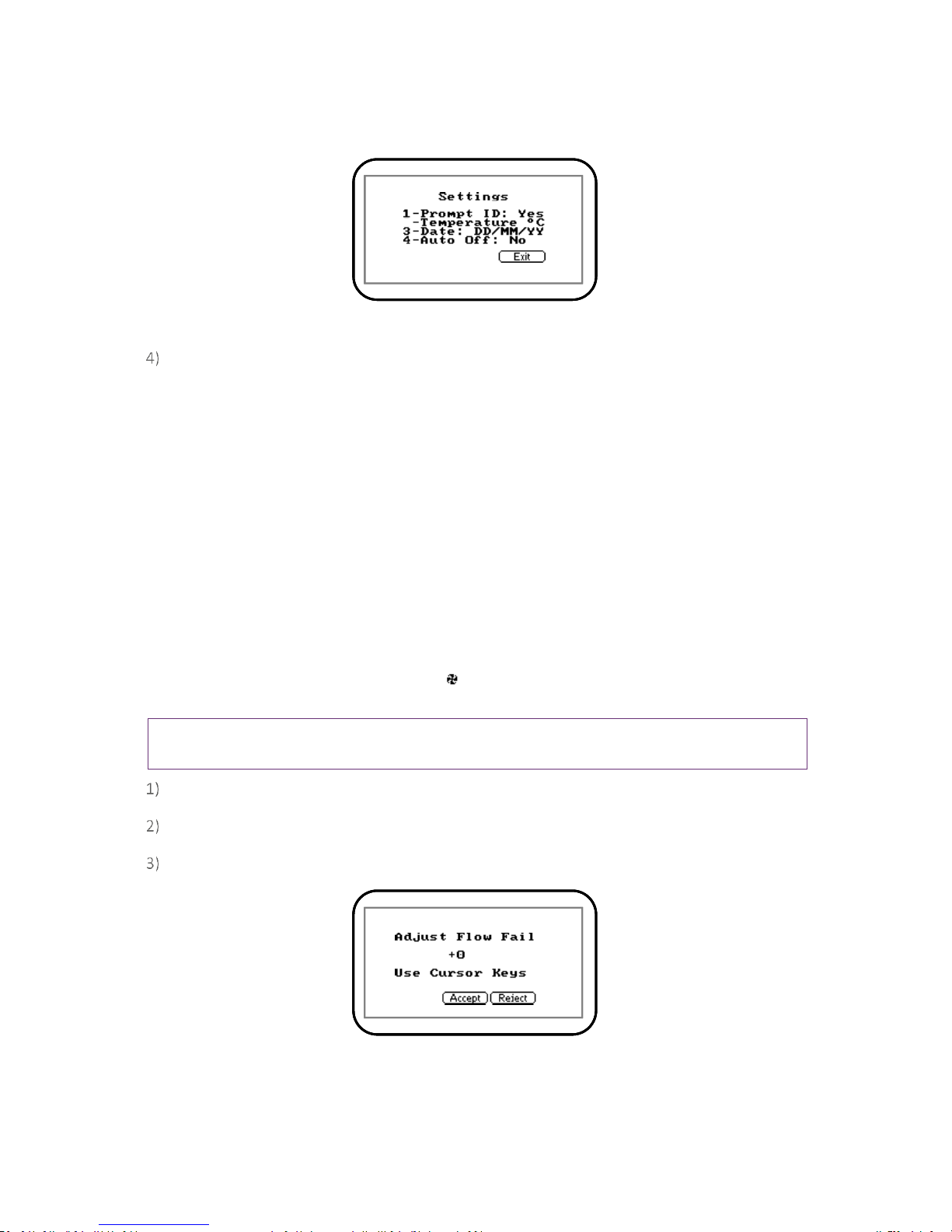
Press ‘Key 4’ to select ‘Settings’ and the following screen is displayed:
Page 25
Page 25 of 61
Operating Manual
www.geotechuk.com
OMG200N Iss.04
© QED Environmental Systems Ltd.
G 2 00 R A N G E
Screen 11 - Settings
The following instrument settings may be maintained:
1 – Prompt ID: Press ‘Key 1’ to prompt for ID code for each sample reading, answer ‘Yes’ or
‘No’ accordingly.
* – Temperature: This option is not available on the G200 range of instruments.
3 – Date: Press ‘Key 3’ to switch the date format between dd/mm/yy and mm/dd/yy formats.
4 – Auto Off: Press ‘Key 4’ to auto switch off the instrument when not in use. Toggle between
Auto Off: Yes or No. If set to Yes, the instrument will switch off after ten minutes if not in use.
Flow Fail
The ‘Flow Fail’ option enables the operator to adjust the instrument flow fail detection point should it
fail in normal operation with a clean filter.
The instrument’s internal pump can be stalled when pulling against a vacuum or through a blocked
filter. This is indicated by a flashing pump icon ; to prevent damage to the pump, the pump will
switch off after a few seconds. Press the ‘Pump’ key again to remove the flashing pump icon.
Note: Dirty or discoloured filters should be changed before use. Filters that have drawn in water
should be changed immediately to prevent damage to the instrument.
From the ‘Main Read Screen’ press the ‘Menu’ key on the instrument panel.
Press ‘Key 2’ to display the ‘Utilities’ menu.
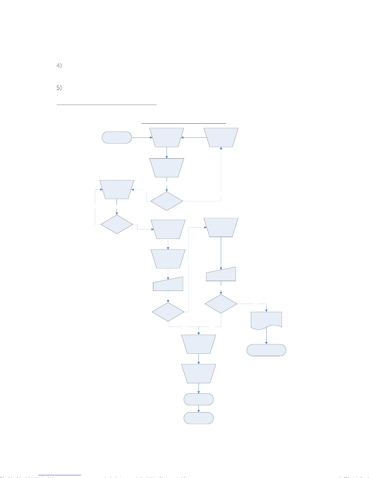
Press ‘Key’ 5 to select ‘Flow Fail’ and the following screen is displayed:
Screen 12 - Adjust flow fail
**
Page 26
Page 26 of 61
Operating Manual
www.geotechuk.com
OMG200N Iss.04
© QED Environmental Systems Ltd.
G 2 00 R A N G E
Use the scroll keys ‘Key 4 – Scroll Left’ or ‘Key 6 – Scroll Right’ to adjust the value displayed. The
larger the value, the less sensitive the flow fail detection is.
Press soft-key ‘Accept’ or ‘Reject’ accordingly.
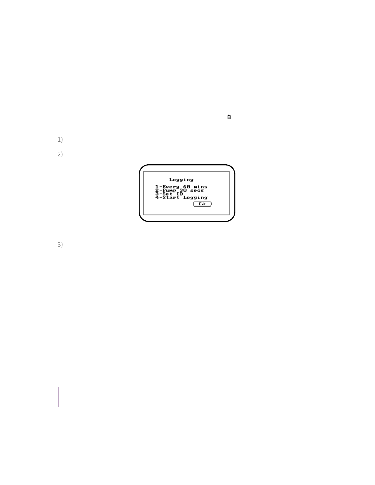
Flow Fail Set-up Process – Best Practice:
Make sure that you have carried out the Preliminary Checks Best Practice before commencing the
Flow Fail Set-up. Refer to section Preliminary Checks - Best Practice for more information.
Increase
the
displayed
value by 2
Flow fail
alarm?
Flow fail
alarm?
No
Wait 5 seconds
No
Block gas inlet
Flow fail
alarm?
Wait 5 seconds
No
Block gas inlet
Flow fail
alarm?
Wait 5 seconds
Accept
Blocked or
excessive
restriction
No
Wait 5 seconds
Flow Fail Set-up Process
Best Practice
G200 Range
Decrease
the
displayed
value by 1
Increase
the
displayed
value by 3
Decrease
the
displayed
value by 1
Decrease
the
displayed
value by 1
END
Refer to Section 8.0
Problem Solving
START
Turn pump
on
Turn pump
on
Press pump
cancel
alarm
Yes Yes
Press pump
cancel
alarm
Yes
Page 27
Page 27 of 61
Operating Manual
www.geotechuk.com
OMG200N Iss.04
© QED Environmental Systems Ltd.
G 2 00 R A N G E
Logging
Data logging mode can be started or stopped via ‘Key 6 - Logging’ accessed from the ‘Utilities’ menu.
Press ‘Key 4 – Start/Stop Logging’ to start and stop data logging.
Whilst in data logging mode the instrument will automatically record data at the preset intervals,
including running the pump for a preset time.
Active logging mode is indicated on the ‘Main Read Screen’ by the icon.
The operator is able to edit the default ID, pump run-time interval, set IDs and start/stop logging.
From the ‘Main Read Screen’ press the ‘Menu’ key on the instrument panel.
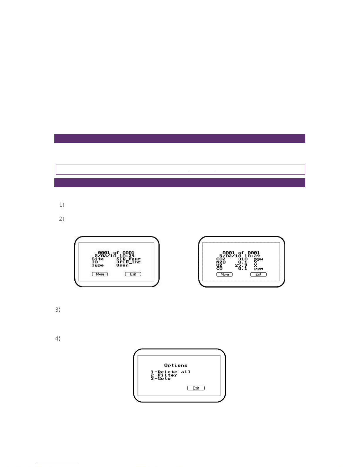
Press ‘Key 6’ to display the ‘Logging’ menu and the following screen is displayed:
Screen 13 - Logging menu
Select the desired option by pressing ‘Keys 1 to 4’. Then enter the appropriate setting using the
keypad followed by the ‘Enter’ key.
1 – Every 00 Mins: Press ‘Key 1’ to enter the time in minutes for the time frame between
sample readings. The interval controls the reading frequency in minutes, i.e. every ten
minutes.
2 – Pump 00 secs: Press ‘Key 2’ to enter the time in seconds for the length of time you wish
the pump to run when taking a sample reading. The pump run-time is the time in seconds for
which the pump runs prior to the reading being stored. This figure will also need to take into
account the length of sample tube and the volume of the sample gas. For example, there is
little point setting a pump run-time of ten seconds if it takes 30 seconds to draw in a new
sample.
3 – Set ID: Press ‘Key 3’ to create eight digit alpha-numeric ‘Site’ and ‘ID’ identifiers.
4 – Start/Stop Logging: This option is only available once an I.D. has been created by the user.
Press ‘Key 4’ to start and stop data logging.
Note: Data logging mode is automatically stopped when the instrument is switched off or if the
logging parameters are edited.
Page 28
Page 28 of 61
Operating Manual
www.geotechuk.com
OMG200N Iss.04
© QED Environmental Systems Ltd.
G 2 00 R A N G E
Reset
The instrument can be reset by pressing ‘Key 7 - Reset’ accessed via the ‘Utilities’ menu. Selecting this
option will clear all user settings and any stored data including the event log.
The following warning message will be displayed ‘This will clear user calibration and readings! Are you
sure?’ The operator is prompted to either select the ‘Accept’ button to continue or select the ‘Exit’
button to abort the reset operation.
If the operator chooses to accept a confirmation code (12345678) must be entered to confirm that a
reset is really required.
Calibration
The G200 range of instruments is fully calibrated during manufacture and when returned for service.
However, to improve accuracy between services a user/field calibration can be performed.
Note: For further information please refer to section Calibration of this manual.
View Data
The ‘View Data’ option enables the operator to view the stored readings.
From the ‘Main Read Screen’ press the ‘Menu’ key on the instrument panel.
Press ‘Key 4 - View Data’ to view the stored data readings and the following screens are
displayed:
Screen 14 - View data 1
Screen 15 - View data 2
Press ‘Key 4 - Scroll Left’ and ‘Key 6 - Scroll Right’ to move through the stored readings either
forwards or backwards. Press ‘Key 2 - Scroll Up’ and ‘Key 8 - Scroll Down’ to switch between the
first and second group of reading parameters.
Press the soft-key ‘More’ and the following menu is displayed:
Screen 16 – Soft-key ‘More’
Page 29
Page 29 of 61
Operating Manual
www.geotechuk.com
OMG200N Iss.04
© QED Environmental Systems Ltd.
G 2 00 R A N G E
1 – Delete All: Enables the operator to delete all the readings stored,
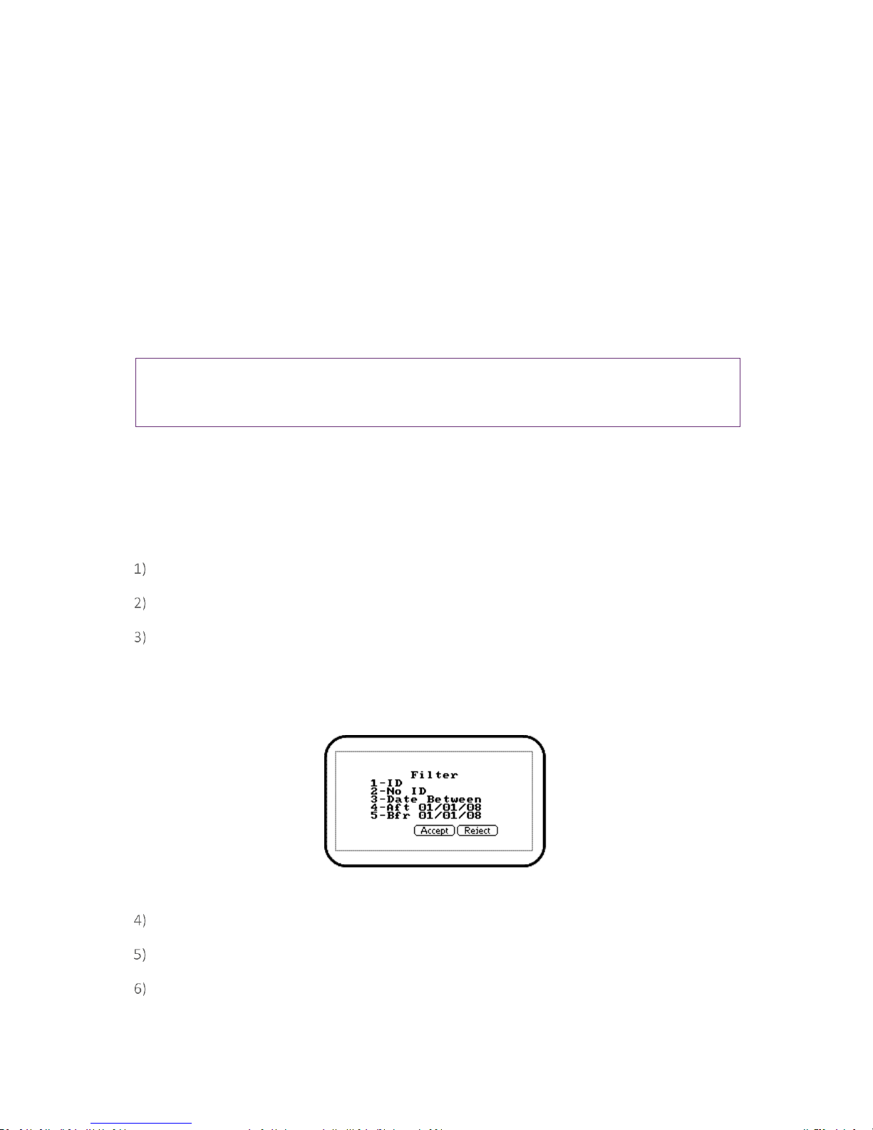
2 – Filter: Used to refine/filter the range of readings displayed by ID or date ranges. Press
between two dates, after a date, before a date or all dates.
3 – Go to: Enables the operator to jump to the first or last reading in the memory or any other
reading.
Delete All
The ‘Delete All’ function enables the user to check how many readings have previously been taken
and clear them if necessary.
Note: Before readings are actually deleted a caution message is displayed; once readings have
been deleted they cannot be recovered. To enable TWA to be calculated the last 24 hrs worth of
readings are stored.
The instrument can store up to 1,000 readings. The reading structure is fixed and may contain
optional parameters not activated for your particular instrument configuration, i.e. oxygen,
temperature and humidity.
Once the reading memory is full it is not possible to store any more readings. When full and the
‘Store’ key is pressed or data logging is activated the instrument will show a brief message stating that
the memory is full and that no further data will be recorded.
From the ‘Main Read Screen’ press the ‘Menu’ key on the instrument panel.
Press ‘Key 4 - View Data’.
To clear the readings press the soft-key ‘More’ followed by ‘Key 1 - Delete all’.
Filter
The ‘Filter’ function enables the user to filter the data readings using all or any combination of the
following filter options:
Screen 17 - Filter
From the ‘Main Read Screen’ press the ‘Menu’ key on the instrument panel.
Press ‘Key 4 - View Data’.
To clear the readings press the soft-key ‘More’ followed by ‘Key 2 - Filter’.
Page 30
Page 30 of 61
Operating Manual
www.geotechuk.com
OMG200N Iss.04
© QED Environmental Systems Ltd.
G 2 00 R A N G E
Press the appropriate menu key to select the required filter option and enter the filter data.
Select the ‘Accept’ button to confirm the filter selection.
Go to
The ‘Go to’ function enables the operator to view the first, last or specific number of reading stored.
From the ‘Main Read Screen’ press the ‘Menu’ key on the instrument panel.
Press ‘Key 4 - View Data’.
To clear the readings press the soft-key ‘More’ followed by ‘Key 3 - Goto’.
Select either ‘First’, ‘Last’ or ‘Num’. If ‘First’ or ‘Last’ is selected the appropriate data will be
displayed.
If ‘Num’ is selected the operator is prompted to enter the data reading number followed by the
‘Accept’ button to confirm the selection.
Diagnostics
The ‘Diagnostics’ option enables QED Technical Support to identify and resolve issues with the
instrument and readings. If required, the operator may be asked to confirm the diagnostics displayed.
From the ‘Main Read Screen’ press the ‘Menu’ key on the instrument panel.
Press ‘Key 5’ to view diagnostics.
Note: For further information contact Technical Support at QED on +44(0)330 800 0088 or email
Monitor (G200 ONLY)
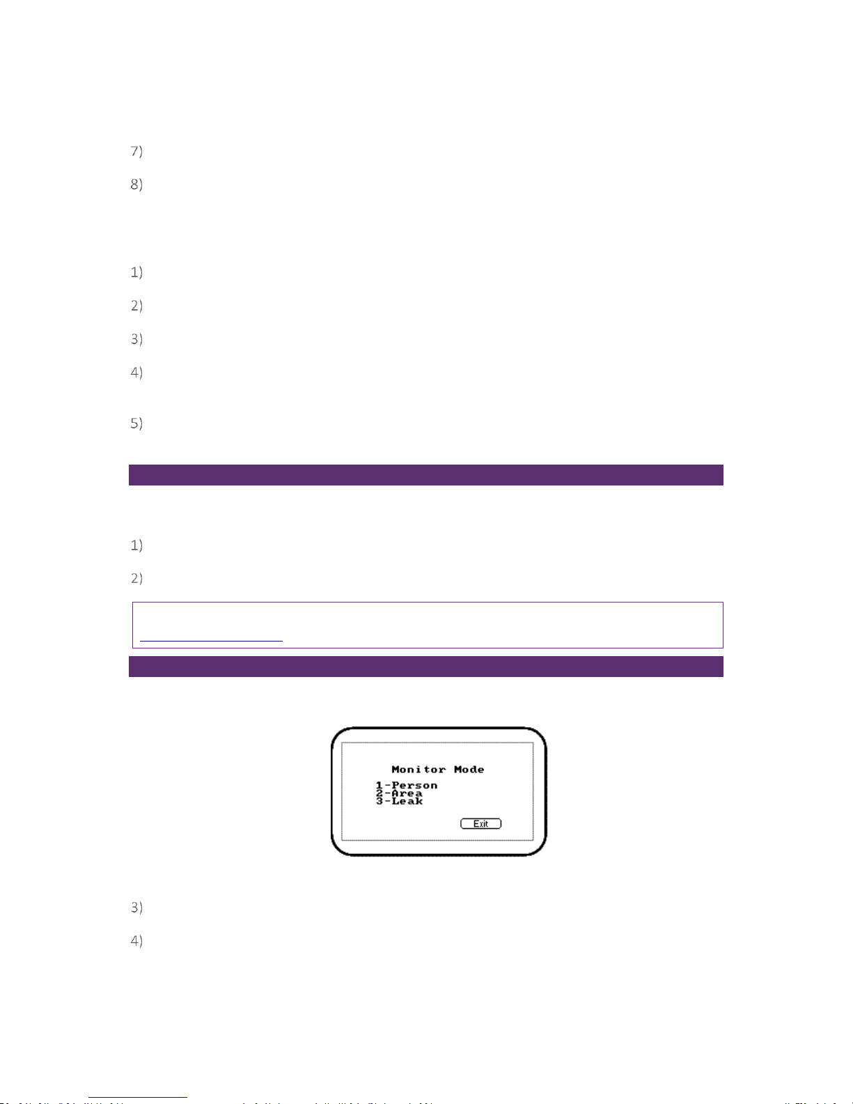
The ‘Monitor’ option enables the operator of a G200 instrument to choose from the following three
monitoring modes.
Screen 18 - Monitor mode
From the ‘Main Read Screen’ press the ‘Menu’ key on the instrument panel.
Press ‘Key 6’ followed by the relevant option key to select the required monitoring mode.
Page 31

Page 31 of 61
Operating Manual
www.geotechuk.com
OMG200N Iss.04
© QED Environmental Systems Ltd.
G 2 00 R A N G E
Person
‘Person’ enables the operator to monitor in personal safety mode. This mode automatically stores
an average N2O reading every 15 minutes. This is used to calculate and display an eight hour TWA
(time weighted average) reading which is the operator’s personal exposure level to N2O over their
working day (often called OEL - occupational exposure limit).
The TWA is measured over a 24 hour period.
The TWA calculation used by the instrument is that described by the Health and Safety Executive
EH40/2002 Occupational Exposure Limits 2002. The TWA is represented mathematically by the
following equation:
(C1T1 + C2T2...CnTn) / 8hrs.
Where C1 is the average reading for the time period T1.
In this mode the instrument will alarm when the operator has exceeded the recommended TWA limit
(the OEL for N2O = 100ppm). This operating mode incorporates a confidence chirp which sounds
every 30 seconds to give the operator confidence that the monitor is still operating correctly. There is
also an option which allows the operator to set an additional alarm for the actual N2O level, i.e.
greater than 300ppm.
It is possible using Analyser Data Manager to change the OEL level for the TWA limit (default
100ppm). We would also recommend that the operator changes the ‘Site’ and ‘ID’ fields to ‘Site’ and
‘Name’ using the ‘Configuration’ tab.
Once IDs have been selected and accepted, readings commence immediately and are monitored
continuously. To stop monitoring the operator selects the soft-key ‘Person’, enters the stop code
5709 and presses the ‘Enter’ key. Readings are automatically stored.
The following points should be noted.
The 15 minutes averages used for the TWA calculation are the result of readings taken each
second. Thus short peaks of concentration will be correctly recorded and added into the TWA
If the instrument is turned off when in ‘Person’ mode, the readings will be assumed to be zero
for the TWA calculation during the time when the instrument is off.
The TWA value displayed on the instrument is not downloaded to Analyser Data Manager
(ADM). ADM recalculates the TWA based on the downloaded raw data and user set parameters.
Area:
‘Area’ enables the operator to monitor in area or room mode. This mode automatically stores a rolling
average N2O reading every ‘n’ minute(s). It is indicated by ‘AV’ on the screen.
The calculation is represented mathematically by the following equation: (C1 + C2...Cn) / elapsed time
in hrs.
This mode would typically be used to monitor a ventilation system in an operating theatre or similar
where N2O is used throughout the day with different people coming and going. Primarily for room or
area monitoring, this mode is intended to give the operator a little more flexibility and can be user
modified to suit the application. The monitoring interval and duration can be adjusted by the
operator. There are alarm options which allow the operator to set an alarm for the average and
Page 32

Page 32 of 61
Operating Manual
www.geotechuk.com
OMG200N Iss.04
© QED Environmental Systems Ltd.
G 2 00 R A N G E
actual N2O levels, eg greater than 300ppm.
As with previous modes it is possible using Analyser Data Manager to change the ‘Site’ and ‘ID’ fields
to ‘Site’ and ‘Room or Area’ using the ‘Configuration’ tab.
Once IDs have been selected and accepted, readings commence immediately and are monitored
continuously. To stop monitoring the operator selects the soft-key ‘Area’, enters the stop code 5709
and presses the ‘Enter’ key. Readings are automatically stored.
Leak Detection:
‘Leak’ enables the operator to monitor the instrument in leak detection mode. This extends the range
of the N2O sensor up to 10,000ppm and speeds up the response time to enable it to indicate the
current level of N2O. This allows the instrument to work as an effective leak monitor. The operator
gets audio and visual feedback in addition to the displayed value to help with this. The back-light
changes from green-thru-yellow to red as the gas concentration increases. And the instrument’s
beeper also increases in frequency and tone to further help bring attention to any gas detected.
There are no additional user alarms or setting for this mode. It is not possible to store data whilst in
this mode.
The operator starts and stops monitoring by selecting the soft-key ‘Leak’.
Note: When monitoring gases using any of the above methods the ‘Mute’ key may be activated to
eliminate the instrument monitoring sound.
TWA and Average Calculations in ADM
This section explains how the Average and Time Weighted Average (TWA) calculations work with the
Analyser Data Manager (ADM) software.
The following parameters are optionally calculated by ADM and use the set of data currently selected
in ADM by the ID, time filters and serial number selection.
Average (ppm)
Average (ppm) = (AvgN2O1 x AvgPeriod1 + AvgN2O2 x AvgPeriod2 + AvgN2On x AvgPeriodn ) / numberof-minutes from first to current filtered reading.
Note: The results in this column may change when the filter(s) are changed.
Note: The definition of the parameters of the calculation can be altered within ADM on the
Configuration tab.
TWA (ppm)
TWA (ppm) = (AvgN2O1 x AvgPeriod1 + AvgN2O2 x AvgPeriod2 + AvgN2On x AvgPeriodn) / 8 hours. The
data is taken as a 24 hour window extending backward through the filtered entries.
Any missing entries within the 24hr window are assumed to be 0ppm.
Selecting the TWA filter affects the appearance of the data when it is charted within ADM, the data
between available recorded data is shown as a zero.
The definition of the parameters of the calculation can be altered within ADM, the default
configuration at installation matches the EH-40 standard.
Page 33
Page 33 of 61
Operating Manual
www.geotechuk.com
OMG200N Iss.04
© QED Environmental Systems Ltd.
G 2 00 R A N G E
Notes:
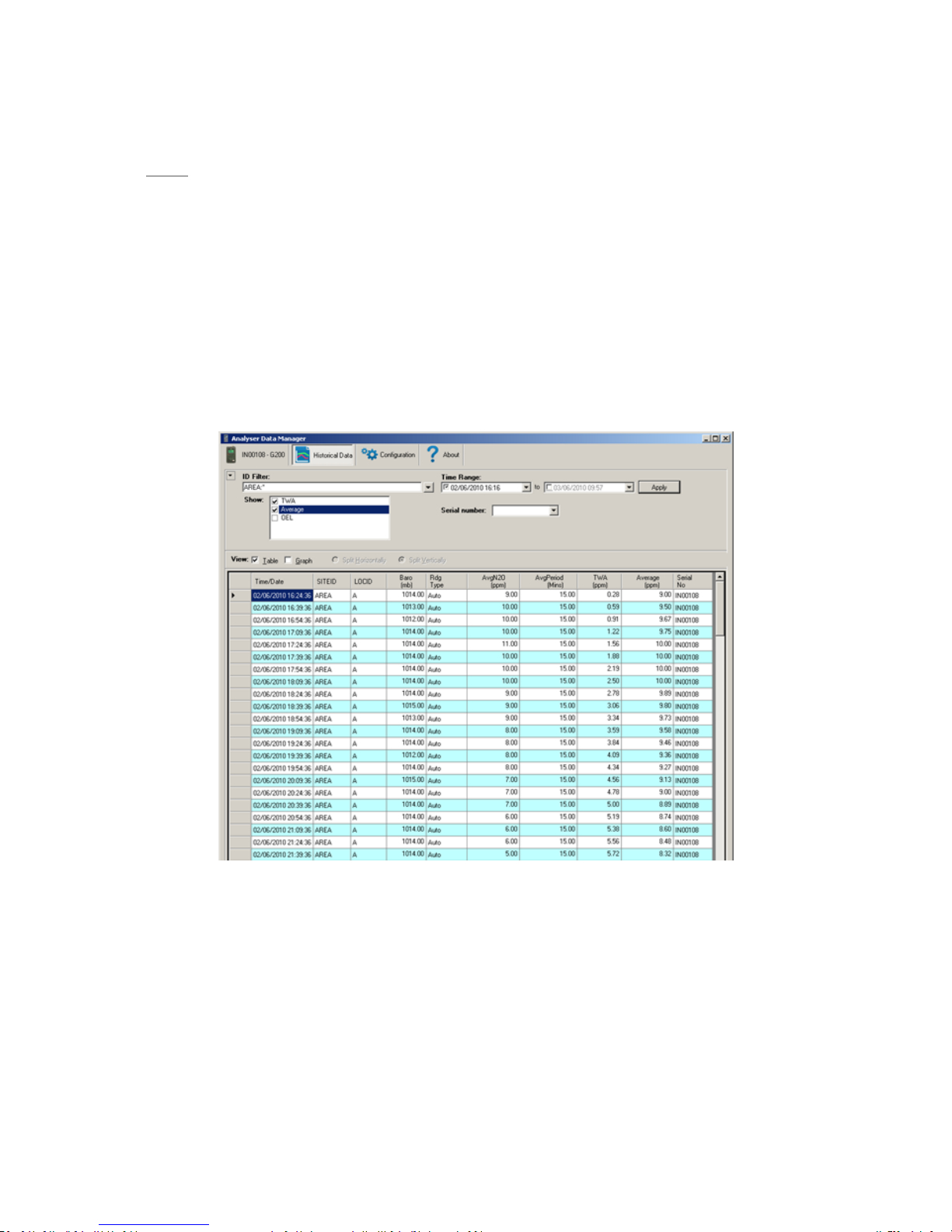
The TWA, Average and OEL checkbox options in ADM are columns of data that are calculated
when the data is displayed, based on the data previously downloaded and stored from the
instrument. The values do not come from the instrument.
Adding the TWA column causes ADM to show an additional 24 hours of “zero” readings so the
user can see the TWA value decay back to 0.
Adding any of these calculated columns makes more sense when choosing data from a single
identifier (Person or Area) using the ID Filter.
Adding any of these calculated columns is optional depending on the application but is
provided for user flexibility.
Figure 3 - Example of Data recorded on the Analyser in Area mode, and then ADM calculating the TWA and
Average Columns
Page 34
Page 34 of 61
Operating Manual
www.geotechuk.com
OMG200N Iss.04
© QED Environmental Systems Ltd.
G 2 00 R A N G E
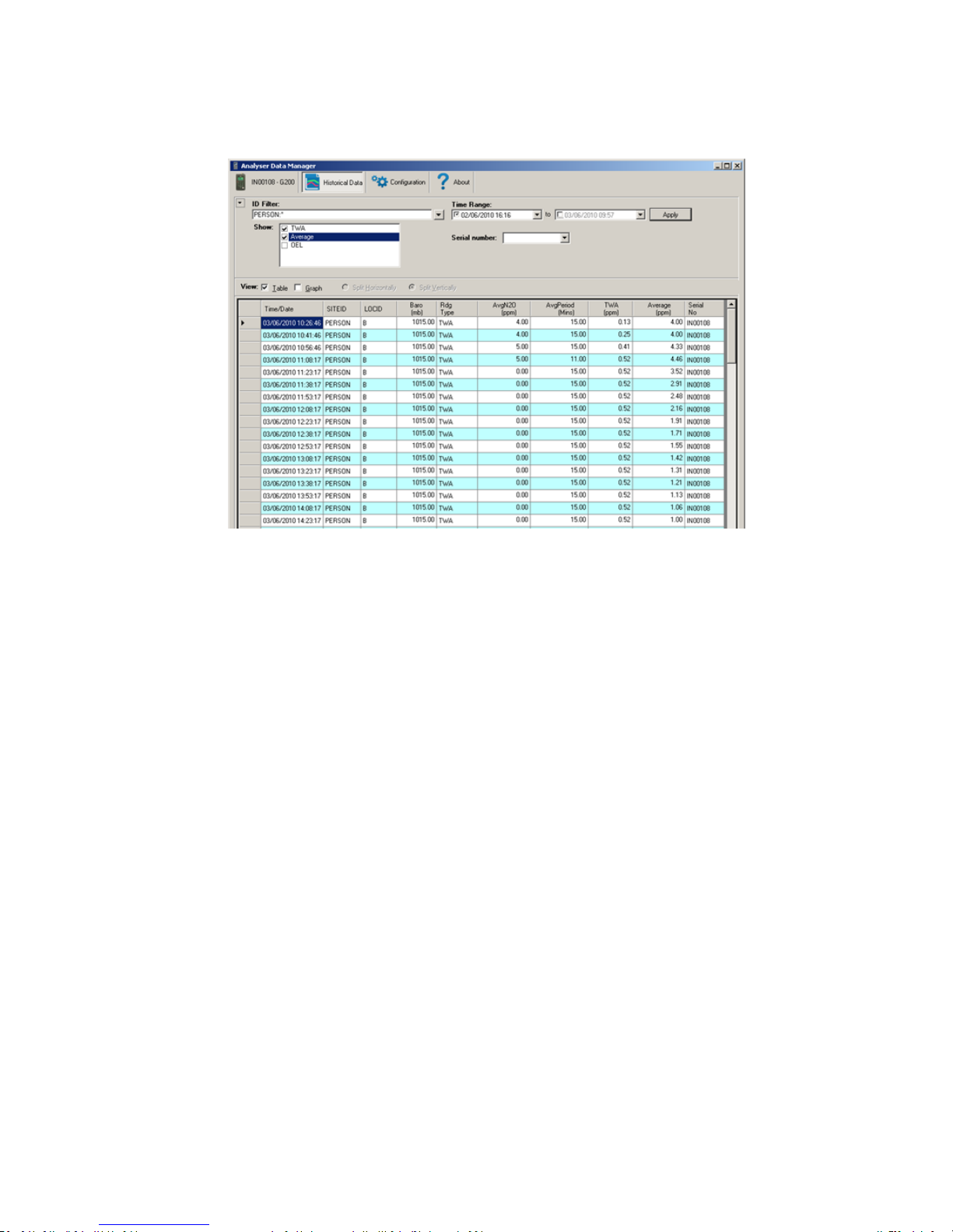
Figure 4 - Example of Data recorded on the Analyser in Person mode, and then ADM calculating the TWA and
Average Columns
Page 35
Page 35 of 61
Operating Manual
www.geotechuk.com
OMG200N Iss.04
© QED Environmental Systems Ltd.
G 2 00 R A N G E
TAKING READINGS
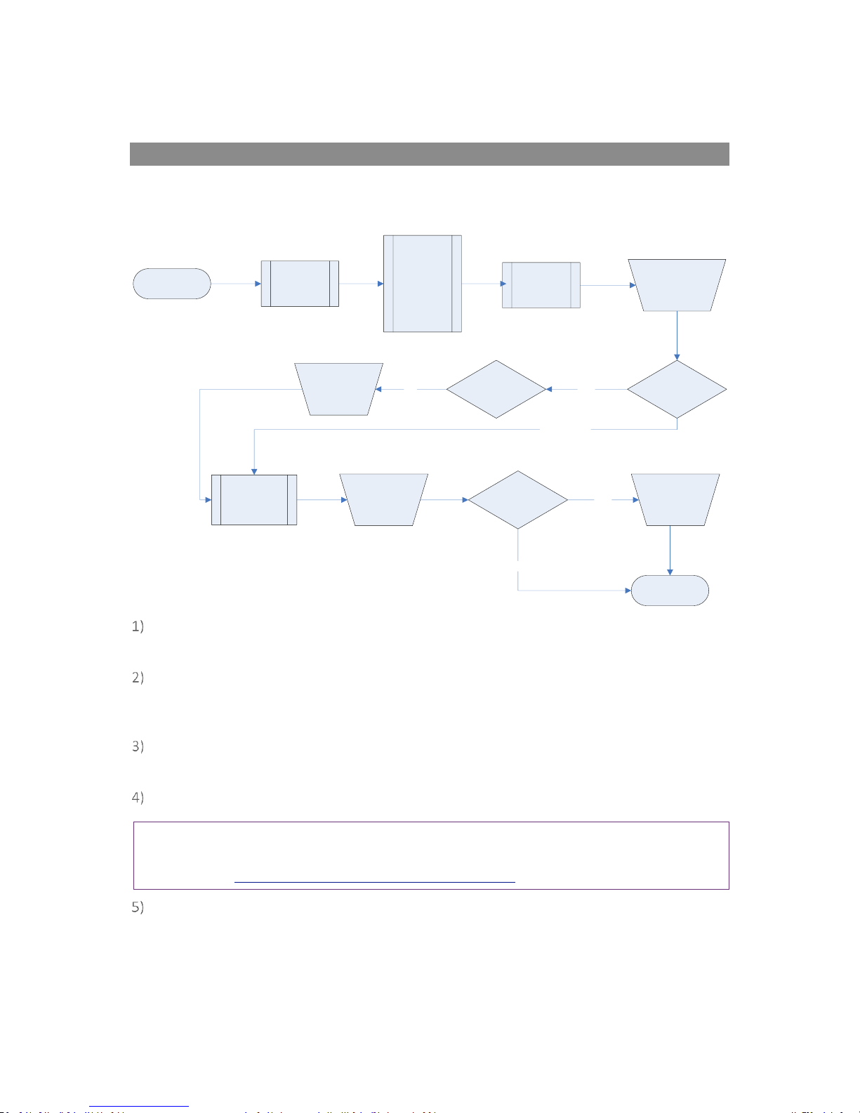
Preliminary Checks - Best Practice
Always ensure that the exhaust gases emerge in a safe manner into a well-ventilated area.
Prior to use, it is good practice to ensure that:
Step 1 The instrument has the correct time and date
set.
Step 2 Check that the sample filter is fitted and that it
is clean and dry.
Step 3 Attach the soda lime CO2 filter (G200 model
only).
Step 4 Attach the pressure regulator (G210 model
only).
Step 5 The battery has a good charge (minimum 25%
charge, even if only a few readings are required).
Step 6 The memory has sufficient space available
(G210 model only).
Step 7 Verify that the main gases have been autozeroed, without gas concentration present.
Note: The unit should be left to reach thermal
equilibrium before zeroing, see note in Zero
Calibration.
Step 8 Verify the span calibration with a known
concentration calibration-check gas.
Step 9 Instrument is ready to take readings.
Do protect the instrument from strong direct sunlight
which will quickly raise the temperature of the
instrument beyond its operating range and the LCD
display will appear almost black. The contrast setting
cannot then alter the contrast.
Do remember to always use the sample filter! If the
sample filter becomes contaminated, change it and
ensure all sample tubes are clean and dry before reuse.
Do not place the instrument against anything hot as
this may cause excessive internal temperatures, which
can lead to erroneous readings.
Instrument
has correct
time and
date set
Preliminary Checks
(G200 Range - Best Practice)
Attach the
Soda Lime
Filter
Start
Instrument is ready
to take readings
Step 1
Attach
Sample
Filter
Memory has
sufficient
space
Verify Zero
Calibration
Verify Span
Calibration
Step 2
Step 3
Step 8
Step 9
Step 7
G200 ONLY
G210 ONLY
Attach the
Pressure
Regulator
Battery has
good charge
Step 4
Step 6
Step 5
G210 ONLY
Page 36
Page 36 of 61
Operating Manual
www.geotechuk.com
OMG200N Iss.04
© QED Environmental Systems Ltd.
G 2 00 R A N G E
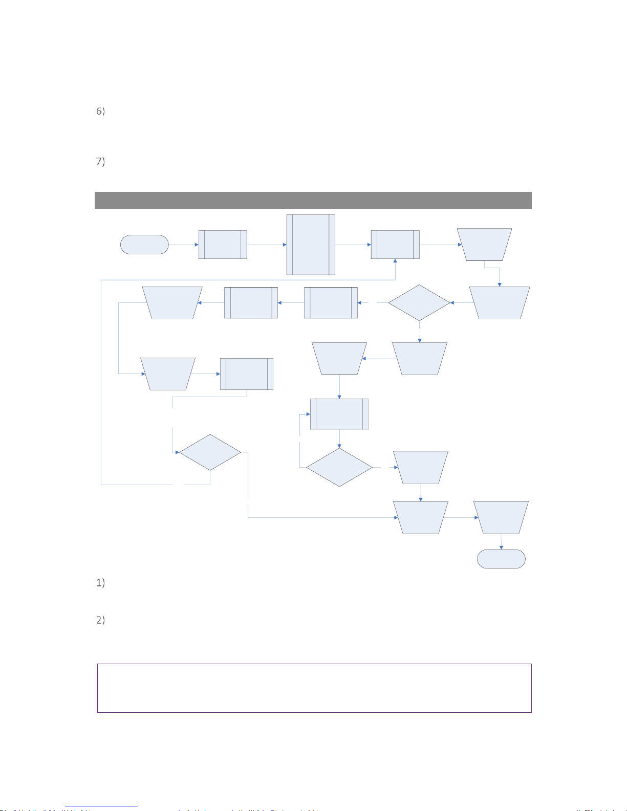
G200 Gas Measurement Process – Best Practice
Depending on preferences the exact reading procedure can change. The following methods are
considered best practice and when followed correctly will allow quick and consistent readings to be
recorded.
Gas Measurement Process
(G200 - Best Practice)
Make sure
you have
carried out
all the
preliminary
checks prior
to taking a
reading
Main Read
Screen
Select mode
Log in
Start
Auto monitoring
is enabled
Enter or
select site
ID &
sample
point code
END
Select soft
key for
mode to
stop
logging
ID Code
prompt field
On/Off?
ON
(Switch on)
Instrument
warm up
Person or Area
Mode?
YES
NO
LEAK MODE
Person or Area
Mode?
Enter stop
code to exit
logging &
press enter
YES
NO
When the instrument is first switched on it should be purged with fresh air and allowed to
stabilise for a few minutes.
Make sure that you have carried out all the preliminary checks as listed in section ‘6.1
Preliminary Checks – Best Practice’ and that the instrument is ready to take the first reading.
Always use a sample filter and a soda lime filter with a G200 instrument.
Connect the sample tube, if relevant, from the sample point to the inlet port of the instrument,
ensuring the filter is seated correctly.
From the ‘Main’ menu select the mode in which you wish to operate the instrument.
Note: Although the G200 analyser is intended for use in a specific mode, i.e. Person, Area or Leak,
the analyser may be used to take readings without a mode specified. For more information please
refer to section G210 Gas Measurement Process – Best Practice.
If ‘Person’ or ‘Area’ mode is specified the operator will be prompted to enter a ‘Site’ and ‘ID’ to
identify the reading. If the operator chooses to monitor readings in ‘Leak’ mode then no ID is
required.
Page 37
Page 37 of 61
Operating Manual
www.geotechuk.com
OMG200N Iss.04
© QED Environmental Systems Ltd.
G 2 00 R A N G E
If operating in ‘Person’ or ‘Area’ mode readings are continuously taken by the instrument. To
stop monitoring the operator must select the appropriate ‘soft-key’ and enter the required stop
code.
If operating in ‘Leak’ mode the operator may start and stop monitoring by selecting the
appropriate soft-key.
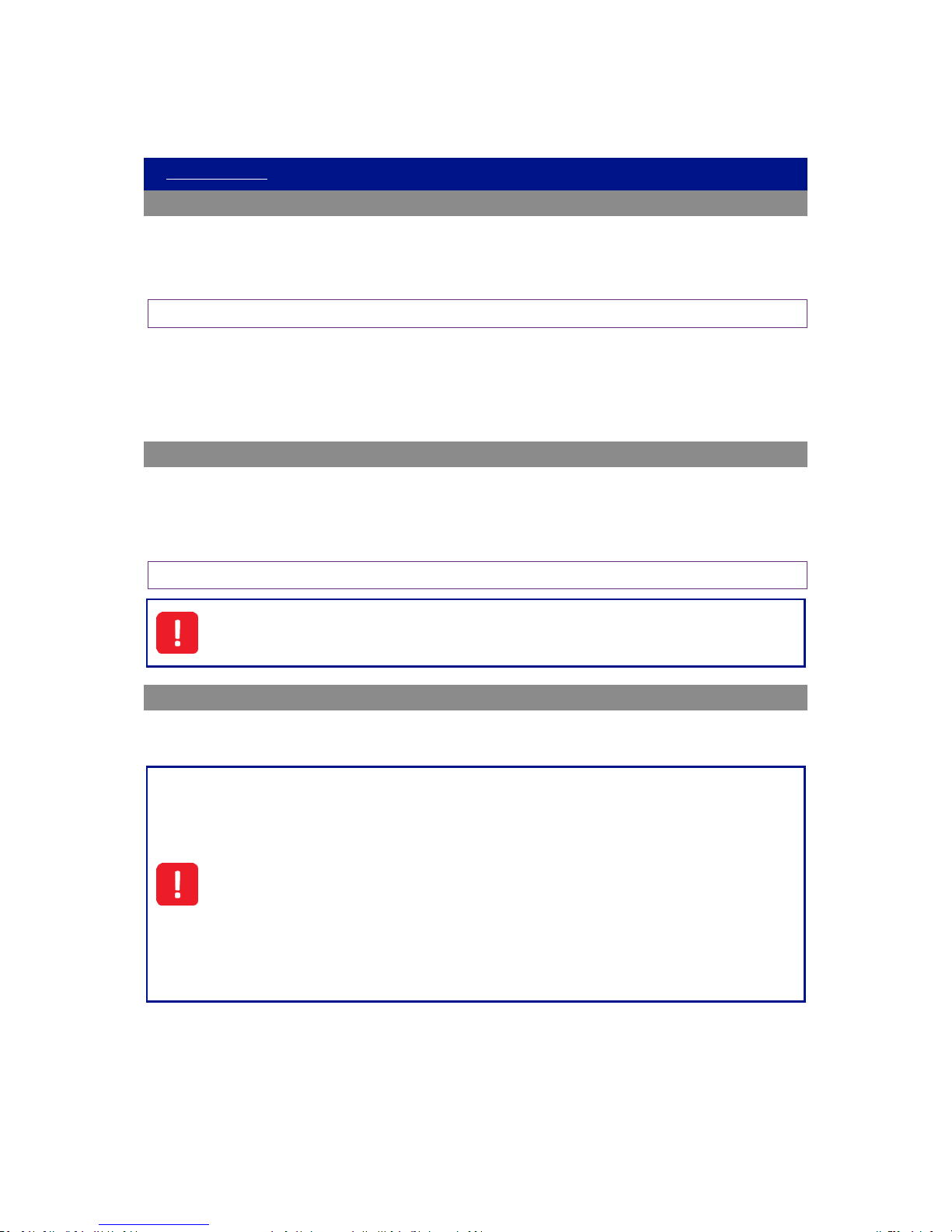
G210 Gas Measurement Process – Best Practice
Gas Measurement Process
(G210 - Best Practice)
(Switch on)
Instrument
warm up
Main Read
Screen
Run a
Clean Air
Purge
Connect
Sample Tube
if required
Start
Reading Stored
(confirmation
message
displayed)
Enter ID
Code
& press
Enter
END
Press the
‘Store’ key
Disconnect
the Sample
Tube from
the inlet
port
Instrument automatically
returns to the
‘Main Read Screen’
Run a
Clean Air
Purge
Make sure
that you
have
carried out
all the
preliminary
checks prior
to taking a
reading
Is Auto-logging
required?
Set ID &
Logging
parameters
NO
YES
Readings are
taken
automatically
Start
Logging
Take another
reading?
Stop
Logging
Gas
measurement is
taken
automatically
Wait for Main
Gas Read
Screen to
stabilise
Take another
reading?
YES
NO
NO
YES
When the instrument is first switched on it should be purged with fresh air and allowed to
stabilise for a few minutes.
Make sure that you have carried out all the preliminary checks as listed in section ‘6.1
Preliminary Checks – Best Practice’ and that the instrument is ready to take the first reading.
Always use a regulator pressure kit with the G210 instrument.
Note: Alternative methods of pressure reduction are available and could be used. However, to
avoid irreversible damage to the instrument, please seek guidance from the supplier/manufacturer
before using any other pressure device.
Page 38

Page 38 of 61
Operating Manual
www.geotechuk.com
OMG200N Iss.04
© QED Environmental Systems Ltd.
G 2 00 R A N G E
Connect the sample tube, if relevant, from the sample point to the inlet port of the instrument,
ensuring the filter is seated correctly.
If auto-logging is required select the ID codes.
If auto-logging is not required, press the pump key to draw a sample, stop the pump and press
the soft-key ‘Store’ to store the reading. The operator will then be prompted to enter or select
ID codes. Select ID codes and press the ‘Accept’ button to confirm. A message will display
confirming that the reading has been stored.
The instrument automatically takes the operator back to the ‘Main Read Screen’ ready to take
another reading.
Page 39
Page 39 of 61
Operating Manual
www.geotechuk.com
OMG200N Iss.04
© QED Environmental Systems Ltd.
G 2 00 R A N G E
CALIBRATION
User Calibration
The G200 range of instruments is fully calibrated during manufacture and when returned for service.
However, to improve accuracy between services a user/field calibration can be performed.
This section sets out the correct procedures to achieve an accurate user calibration.
Note: If the calibration is completed incorrectly it may decrease the accuracy of the instrument.
Two important terms that are used within this section are “Zero” and “Span”.
Zero: The point at which the instrument is calibrated when there is none of the target gas present.
Span: The point at which the instrument is calibrated when a known quantity of the target gas is
present.
Calibration Gases
User calibration of the instrument will improve the data accuracy in the range of the calibration gases
used. However, it may cause less accurate readings of concentrations outside this calibrated range.
Users should select the correct calibration gas for the expected gas levels on their particular
application. Only use gases with a known certified gas concentration.
Note: Certified calibration gases can be supplied by QED.
For each gas used the appropriate material safety data sheet must be read and understood
before proceeding. Calibration gases and the use of pressure regulators can be dangerous.
Calibration Set-up
The regulator supplied with the calibration kit has been configured to deliver a fixed flow. It only
requires a few turns to open and no adjustment is necessary.
Exhaust Port
When the instrument is being calibrated, there are two possible exits for the gas; via the
usual manner out of the exhaust port of the instrument or in cases of over-pressurisation
the 1/16” port on the pressure relief valve.
It is recommended that both ports have exhaust tubing attached. The exhaust tubing must
emerge in a well-vented area. Ensure there are no leaks in the tubing and connections.
The calibration should always be carried out in a safe area with all necessary precautions
taken as all pressurised gases are potentially dangerous.
Page 40
Page 40 of 61
Operating Manual
www.geotechuk.com
OMG200N Iss.04
© QED Environmental Systems Ltd.
G 2 00 R A N G E
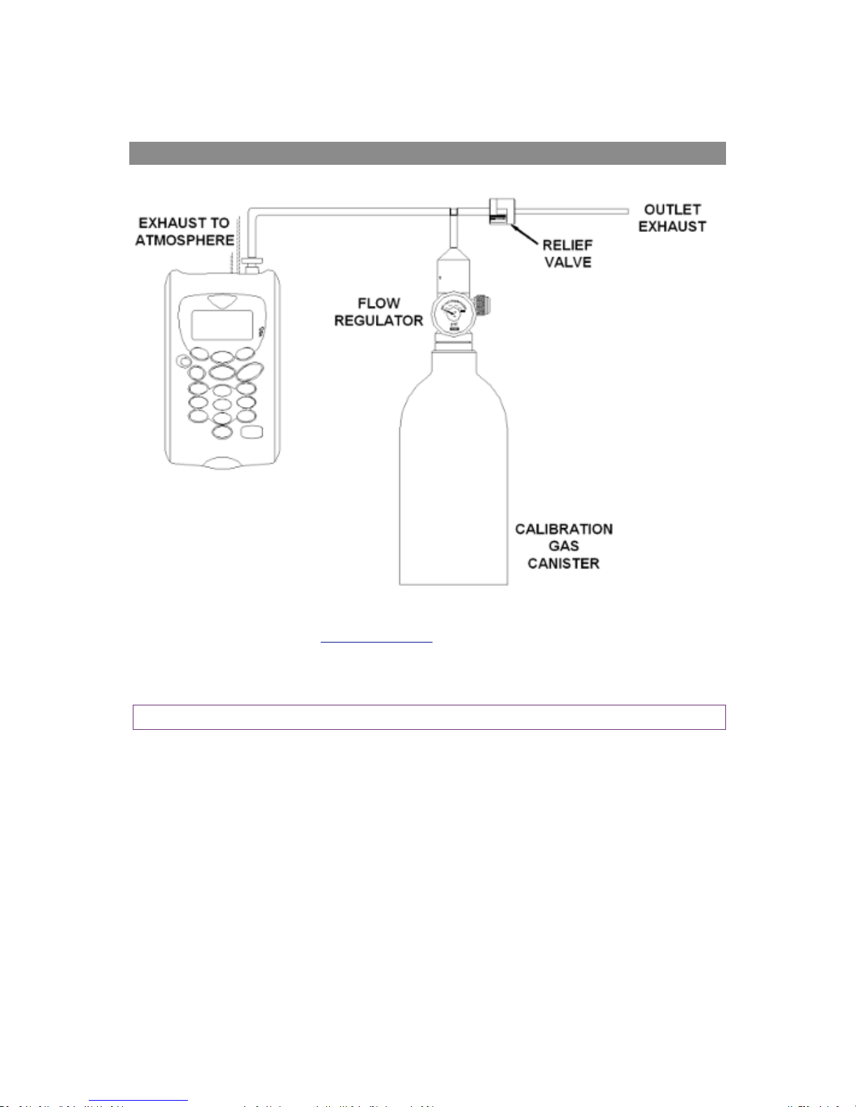
Calibration Equipment
The diagram below displays the regulator and tubing equipment for user calibration:
Certified calibration gas in 58 litre gas canisters is supplied with the QED calibration kit. Please
refer to the QED website www.qedenv.co.uk for further information.
The regulator supplied with the calibration kit is recommended as flow and pressure rates are
factory set.
Note: Maximum input pressure 250mb maximum flow 300ml.
Page 41
Page 41 of 61
Operating Manual
www.geotechuk.com
OMG200N Iss.04
© QED Environmental Systems Ltd.
G 2 00 R A N G E
Calibration Method
Before you begin ensure the unit is turned on and allowed to stabilise at its working temperature
before performing any of the calibration options, this will typically be 15-20 minutes.
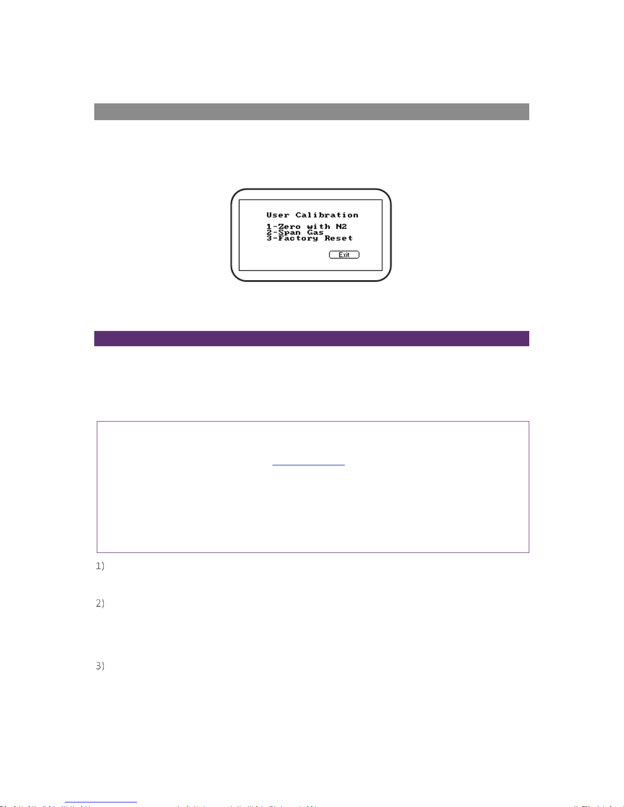
To achieve the processes set out in this section, press ‘Key 3 – Calibration’ from the ‘Main’ menu. The
first screen displayed provides the option to select the gas that requires calibration.
Screen 19 - Calibration menu
The exact calibration method can vary depending on the gases used.
Zero Calibration
For maximum accuracy it is recommended that the measurement channel is zeroed using bottled gas
(certified 100% N2). Due to the CO2 cross-gas effect on N2O, if nitrogen gas is not available the
optional soda lime CO2 filter kit can be fitted to the gas inlet. This allows the user to perform a zero
using normal air as the soda lime CO2 filter will absorb virtually all CO2 from the sample air. For both
these options select 'Key 1-Zero with N2' from the user calibration menu.
Note: In normal use, it is recommended that the soda lime CO2 filter kit is always used. This is kit is
not required for normal use of the G210, as it measures CO2 as standard. For further information
about cross-gas effects, refer to section Cross-Gas Effects of this manual.
Note: For all three of the aforementioned methods of zeroing and Air calibrating the instrument, it
is preferred that the instrument is left in its ‘on state’ to reach thermal equilibrium before
completing this process (approximately 40 minutes). However, the instrument can be zeroed or Air
calibrated immediately after turning it on and then subsequently used to measure but this process
must be repeated after the 40 minute thermal equilibrium time.
From the calibration menu, Select ‘Key 1 - Zero with N
2
’ (recommended) and either attach the
100% N2 or soda lime CO2 filter kit.
Press the ‘Start’ key. The instrument will now wait (a minimum of 60 seconds) for the gas
reading to stabilise at the correct level. If zeroing with the soda lime kit in fresh air press the
‘Pump’ key to draw in fresh air. This operation will time out after one hour if readings cannot be
stabilised.
The instrument will then indicate a successful zero has been completed. Press the soft-key
‘Accept’ to confirm the calibration and store the new user offset. Alternatively, soft-key ‘Reject’
to exit without change.
Page 42
Page 42 of 61
Operating Manual
www.geotechuk.com
OMG200N Iss.04
© QED Environmental Systems Ltd.
G 2 00 R A N G E
Note: If the calibration failed then purge and try again or select a different air source.
Note: If using G210 – very high concentrations of CO2 may take up to 30 minutes to purge
completely. O2 is not zeroed.
Span Channels
It is recommended that the instrument is spanned to target the desired reading range (refer to
section Recommended Gases for Calibration of this manual for more information); ideally this should
not be a low level close to zero.
If not already preset, enter the correct span target, i.e. certified concentration of your
calibration gas. Press ‘Key 1’ and enter the new value. Then attach the gas and open regulator
valve to allow the gas to flow.
Press the ‘Start’ key and wait for the reading to stabilise. This can take a couple of minutes.
Press the ‘Pump’ key to draw sample gas.
Once a stable reading is shown press the soft-key ‘Accept’. A successful span calibration
message will then be displayed. Press the soft-key ‘Accept’ again to confirm the calibration and
‘Store’ the new user span. Alternatively, press soft-key ‘Reject’ to exit without change.
Note: If the calibration failed then try again using a longer purge time or different target gas.
Last Field Calibration
This data can be found in the ‘Information’ screen accessed via the ‘Utilities’ menu. This option
displays the date that the last field calibration was performed on the instrument.
Calibration Record
The G200 instruments have the facility to log user calibrations via the ‘Event Log’. This can be used as
an aid in ensuring that gas measurements are valid and accurate.
During calibration the instrument will record the following in the event log. For each entry the time
and date will be stored.
Event
Data Recorded
Successful user zero for selected gas
Type (N2 or Air) and Readings before and after
Successful user span for selected gas
Target Value, Readings before and after
Successful user span for selected gas
Target Value, Readings before and after
Failed user zero for selected gas
Type (N2 or Air) and Reading
Failed user span for selected gas
Target Value, Gas Reading
Failed user span for selected gas
Target Value, Gas Reading
Return to factory settings
Note: If the calibration failed, then try again using a longer purge time or different target gas. This
event log can only be downloaded and viewed via the optional Analyser Data Manager software. It
cannot be viewed on the analyser screen.
Page 43
Page 43 of 61
Operating Manual
www.geotechuk.com
OMG200N Iss.04
© QED Environmental Systems Ltd.
G 2 00 R A N G E
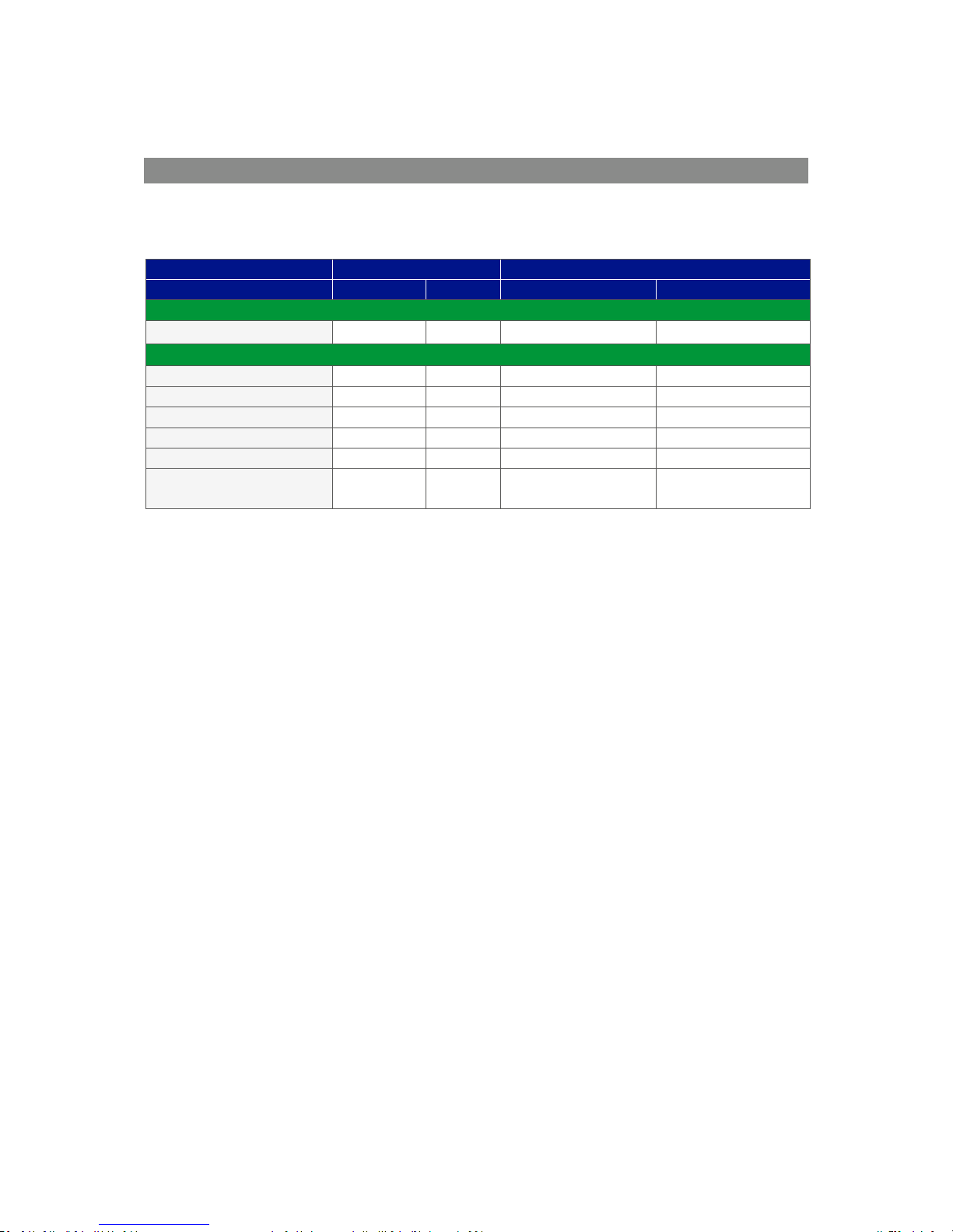
Recommended Gases for Calibration
The calibration gas recommended depends on the desired operation and concentration of target gas.
The following table outlines the recommended gases that can be used for calibrating each of the
measurements.
Instrument
G200
G210
Application
OEL
Leak
N2O 50%, O2 50%
O2 100%, N2O
Zero Calibration Gases
N2 100%
N2O
N2O
O2, N2O, CO, CO2
O2, N2O, CO, CO2
Span Calibration Gases
N2O 100ppm
N2O
N2O 500ppm
N2O
O2 100%
O2
N2O 50%, O2 50%
N2O, O2
N2O 100%
N2O
CO 100ppm,
CO2 500ppm
CO, CO2
CO, CO2
Page 44
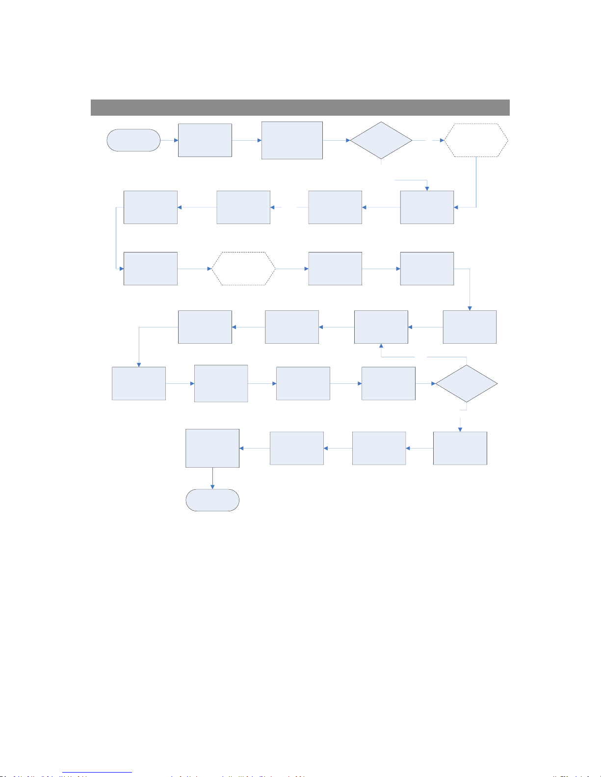
Page 44 of 61
Operating Manual
www.geotechuk.com
OMG200N Iss.04
© QED Environmental Systems Ltd.
G 2 00 R A N G E
G200 Range Calibration – Best Practice
START
Main menu
select Field
Calibration
Select Option 1
Zero N
2
O or
Zero with Air
Return to
Calibration screen
END
Run the pump
Clean Air Purge
Go on to the
Zero gas
process
Stop the pump
Attach tubing and
calibration gas
cannister
Disconnect gas
cannister
Select Option 3
Span Gas
Zero with N
2
or
Zero with Air?
N
2
Press start
Wait for gas to
stabilise
Completed OK
select Accept
WAIT
Connect gas for
Span Calibration
Gas
Go on to the
Span gas
process
Select gas to
Span
Select Option 1
Edit to your
certified gas
concentration
Press Enter
Air
NOT best
practice
Press start target
value
Wait for screen to
stabilise
(Now value should
be close to Ref
value)
Select Accept Select Accept
Disconnect
tubing
Refit the Soda
Lime Filter
Span another
channel?
NO
YES
Page 45

Page 45 of 61
Operating Manual
www.geotechuk.com
OMG200N Iss.04
© QED Environmental Systems Ltd.
G 2 00 R A N G E
PROBLEM SOLVING
This section outlines various warning and error messages which the operator may receive during
general operation of the instrument. For further assistance please contact Technical Support at QED
on +44(0)330 800 0088 or email [email protected].
Warnings and Errors
When switched on the instrument will perform a predetermined self-test sequence taking
approximately 15 seconds. During this time many of the instrument’s working parameters and
settings are checked.
If any operational parameters are out of specification or if the pre-programmed recommended
calibration/service date has passed, errors or warnings may be displayed.
Use the ‘Scroll Up’ and ‘Scroll Down’ keys to move through the list if required.
There are two types of warning that may be displayed:
General warnings that may not affect the instrument’s function and those where the self-test
has detected a function that is outside the usual operating criteria, e.g. battery charge low,
memory nearly full.
Operational parameters that could affect the performance of the instrument, e.g. N2O out of
calibration.
The most likely reason for these errors is either an incorrect user calibration or they may indicate
sensor failure. If an incorrect user calibration has caused the warning it should be correctable by way
of returning the instrument to factory settings, zeroing or carrying out a user calibration as necessary
for the relevant function.
Under and Over Range Codes
If a reading is over range (i.e. above the maximum allowed reading) it will be displayed with more
than chevrons (>>.>). This can occur if a channel has been incorrectly calibrated or the sample gas
has exceeded its specified range (e.g. N2O > 20%).
If a reading is under range (i.e. below zero) it will be displayed with less than chevrons (<<. <). Refer
to section Calibration of this manual to remedy under-range by performing a user zero.
A number displayed as asterisks (**.*) indicates an error, usually where the instrument has been
unable to complete a particular calculation. Typically, this will be the first indication of a fault
condition.
Where no data is available dashes (--.-) are displayed. This usually occurs when a particular reading or
parameter has been skipped by the user, or where an optional accessory is not fitted correctly, i.e. a
temperature probe.
Page 46
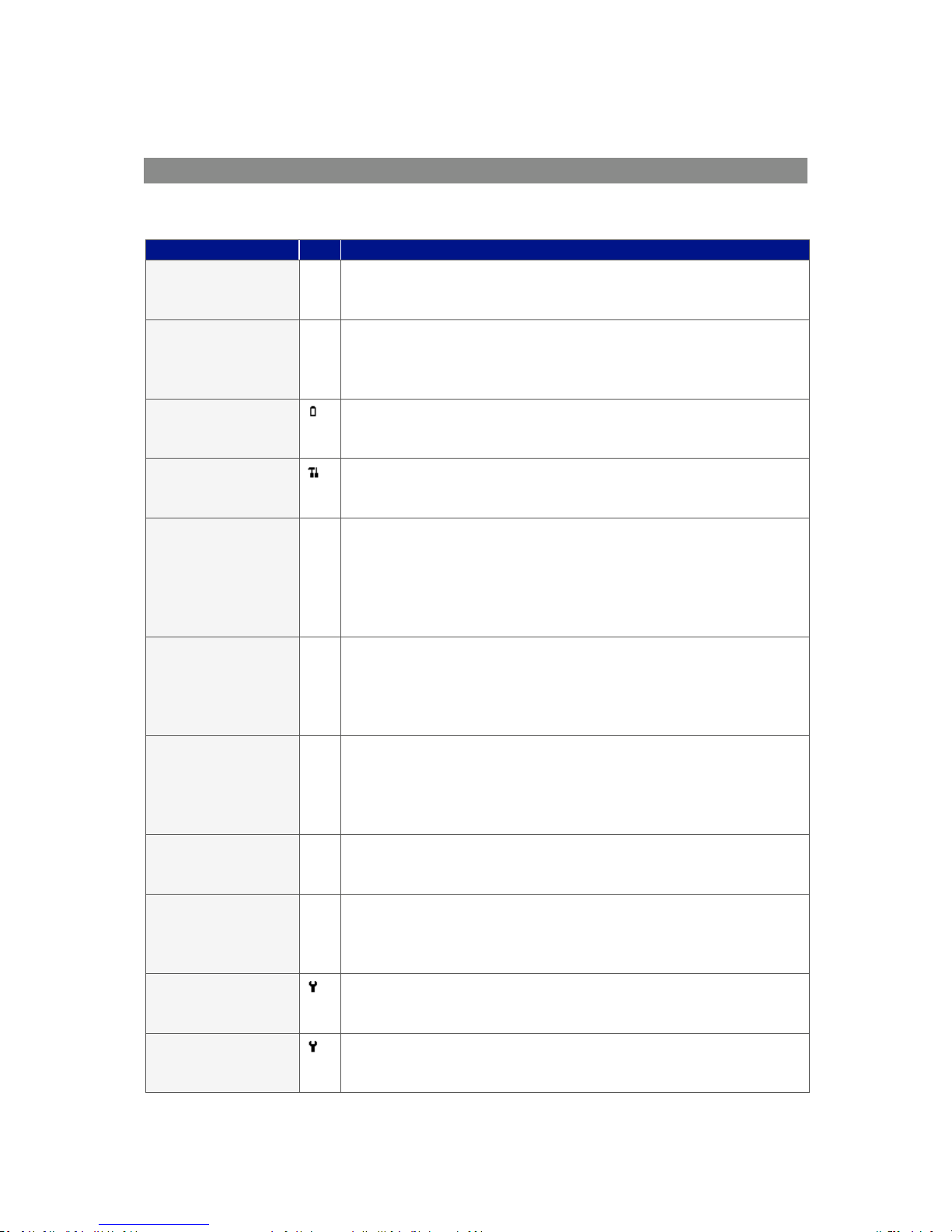
Page 46 of 61
Operating Manual
www.geotechuk.com
OMG200N Iss.04
© QED Environmental Systems Ltd.
G 2 00 R A N G E
Self-test Warning Messages
The following warnings may be displayed during the self-test period when the instrument is switched
ON.
Warning
Description
Check Memory
The instrument only has space to store less than 50 readings before it
is full. The exact number can be checked using the ‘View Readings’
option.
Memory Full
There is no more space in memory to store readings. Both the store
and log options will be disabled until the memory is cleared. The
readings should be downloaded to PC using the optional download
software before memory is cleared.
Battery Low
The instrument does not have enough power to operate for a full day.
The instrument should be recharged or connected to an external
power supply.
Service Due
It has been 12 months (or more) since the instrument was returned
to the manufacturer for a service. The performance and accuracy of
the instrument may be impaired.
Low Flow
The instrument’s gas inlet (or outlet) may be blocked. This warning is
most commonly caused by a water-logged or dirty sample filter.
Change the sample filter and check for obvious blockages in the
sample tubes. Alternatively, a small amount of adjustment can be
made to the low flow detection point to compensate for minor
changes in the performance of the pump fitted to the instrument.
Check N2O Cal.
This warning is most commonly caused by an incorrect user
calibration. Try recalibrating the sensor or press ‘Return to factory
settings’. If the warning persists it may be caused by dirt or damage
to the infrared sensor. The instrument will need to be returned to the
manufacturer for service/repair.
Check O2 Cal.
This warning is most commonly caused by an incorrect user
calibration. Try recalibrating the sensor or press ‘Return to factory
settings’. If the warning persists it may be caused by a damaged or
faulty sensor. The instrument will need to be returned to the
manufacturer for service/repair.
Ref. Fault
This may be caused by dirt or damage to the infrared sensor in the
instrument. The instrument will need to be returned to the
manufacturer for service/repair.
*
Invalid Config.
The instrument has detected a problem with the configuration
parameters most likely caused after a firmware update. The
instrument will need to be returned to the manufacturer for
service/repair.
Change O2 Cell
The oxygen cell has not been changed for at least 3 years; its
performance and accuracy may be impaired. The instrument will
need to be returned to the manufacturer for service.
Change CO Cell
The carbon monoxide cell has not been changed for at least 2 years;
its performance and accuracy may be impaired. The instrument will
need to be returned to the manufacturer for service.
Page 47
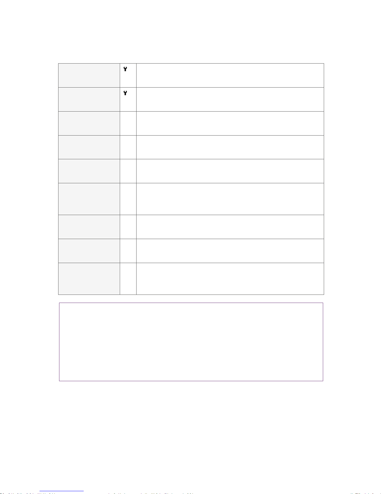
Page 47 of 61
Operating Manual
www.geotechuk.com
OMG200N Iss.04
© QED Environmental Systems Ltd.
G 2 00 R A N G E
Change Pump
The pump has exceeded its recommended run-time and should be
changed. The instrument will need to be returned to the
manufacturer for service.
Change Battery
The Lithium Ion battery has exceeded its recommended life-time or
number of charge cycles and should be changed. The instrument will
need to be returned to the manufacturer for service.
User Cal. Due
It has been over a month since the instrument was last user
calibrated. For optimal performance and accuracy it is recommended
that the instrument is user calibrated each time it is used.
Invalid Time
The instrument has an invalid time. This is most likely to occur after a
reset. The correct time should be entered using the set ‘Time & Date’
option via the ‘Utilities’ menu.
Invalid Date
The instrument has an invalid date. This is most likely to occur after a
reset. The correct date should be entered using the set ‘Time & Date’
option via the ‘Utilities’ menu.
Baro. Fault
The instrument has detected a fault with the barometric sensor or its
calibration. This will have an effect on the accuracy of the readings as
they are pressure compensated. The instrument will need to be
returned to the manufacturer for service.
**Sensor n Failed
Sensor n is expected but not reading a valid value. This is generally a
hardware fault or the instrument has been configured incorrectly.
Please contact the manufacturer.
** Sensor n Range
Sensor n raw value is outside expected range. This is generally a
hardware fault or the instrument has been configured incorrectly.
Please contact the manufacturer.
**Sensor n Stability
Sensor n has not reached a stable value within the warm-up time
limit. The instrument may have been left with gas in. Please purge
and retry. If the instrument shows a stable reading on the main
screen this warning can be ignored.
Note:
*Certain configuration problems can be corrected remotely.
** Where n equals the sensor channel number.
Note: Using the Analyser Data Manager software, it is possible to export the current configuration
and e-mail it to the manufacturer’s Technical Support or Service Department. Depending on the
type of error, it may be possible to correct the configuration file and import it back into the
instrument. For further information please contact QED Technical Support on +44(0)330 800 0088.
Page 48
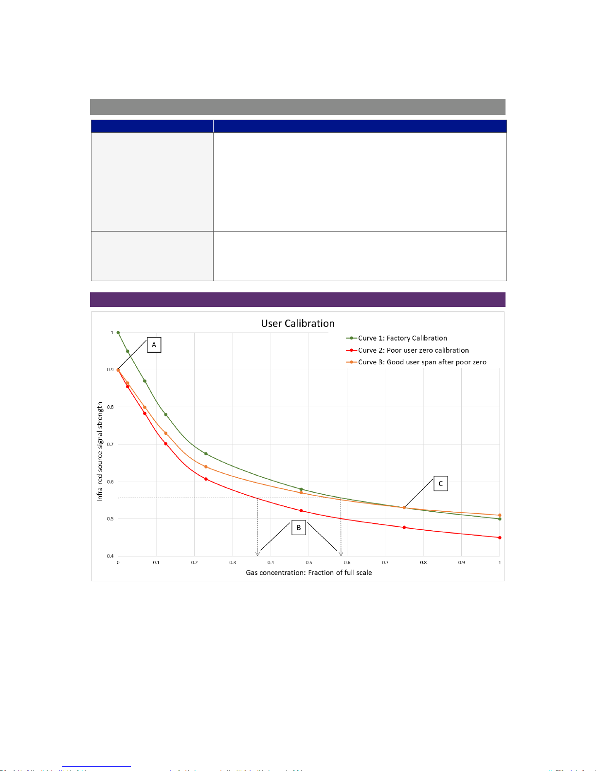
Page 48 of 61
Operating Manual
www.geotechuk.com
OMG200N Iss.04
© QED Environmental Systems Ltd.
G 2 00 R A N G E
User Calibration Trouble Shooting
Error
Remedy
User Zero failed
A possible reason for this is that the instrument is trying to zero to a
level which is outside the predetermined range set when the unit was
calibrated at the factory. To rectify this, first ensure the unit contains
absolutely none of the gas which is being zeroed by flushing
thoroughly with nitrogen. If it will not zero, then refer to the
instructions given in the ‘Factory Settings’ section. If the instrument
continues to fail to zero then the unit must be returned to the
manufacturer for investigation.
Calibration failed
Check the span target is set to the correct value, if not, correct and
retry spanning the channel. Repeat the entire procedure, including
zeroing the channel and then calibrate the span. Ensure the reading
is stable before spanning the channel.
User Calibration Explained:
Graph 1 - User calibration explained
User calibration is a means of optimising the performance of the instrument to the current operating
conditions such as ambient temperature and pressure as well as correcting for instrument drift
caused by lamp and filter settling.
In general, the instrument should not require calibration more than once a month, but we do
recommend verifying the instruments operation each day.
Page 49

Page 49 of 61
Operating Manual
www.geotechuk.com
OMG200N Iss.04
© QED Environmental Systems Ltd.
G 2 00 R A N G E
User calibration has two operations and each may be performed individually, however for a complete
user calibration both must be completed.
Factory Calibration
When the instrument is factory calibrated, a stable gas curve is generated (see curve 1 on Graph 1 -
User calibration explained). This curve is then used to determine the gas concentration based on the
infrared signal strength after being absorbed by the gas.
Zero Calibration
A zero calibration is used to correct the entire curve for the infrared source and filter variations
caused by aging and induced drift due to dirt and other contaminants. If done correctly, there is often
no need to complete a span calibration, as the new curve will follow closely to the factory calibration
curve (curve 1 on Graph 1 - User calibration explained).
The zero calibration is very sensitive and a rushed or poor calibration, (such as the target gas still
being present), will result in a zero error; see point A on curve 2 of Graph 1 - User calibration
explained. This also produces an error throughout the remainder of the curve proportional to signal
strength, but the effect on the span is significant, see point B on Graph 1 - User calibration explained.
Note: To perform an accurate user calibration it is critical that a good user zero has been
performed. QED recommend that this be done in nitrogen in order to guarantee that none of the
gas of interest is present.
Note: The Zero calibration is very sensitive and even 100% instruments will detect in the 0 to
100ppm range even though they do not display to this resolution. Please refer to Graph 2 - Typical
zero gas purge times.
Span Calibration
A span calibration is used to optimise the analyser at the span calibration concentration (see point C
on Graph 1 - User calibration explained) for the current operational conditions. It corrects the span
point but leaves the zero unadjusted (this will be left at the last user zero if this has been performed)
and should be done at the concentration of interest in the particular application.
If the user zero is poor and the span calibration is good, it will correct the gas curve for the point of
interest, but other points on the curve could be incorrect, see curve 3 on Graph 1 - User calibration
explained.
Typical Calibration Purge Times
Typical zero calibration although displaying zero needs to be given time to settle. We recommend
commencing the calibration at least five minutes after the display concentration stabilises.
Page 50
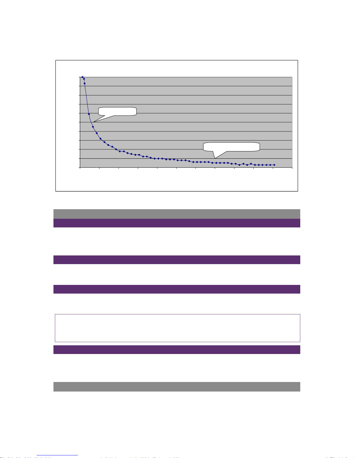
Page 50 of 61
Operating Manual
www.geotechuk.com
OMG200N Iss.04
© QED Environmental Systems Ltd.
G 2 00 R A N G E
Graph 2 - Typical zero gas purge times
Cross-Gas Effects
CO2 Cell
Carbon dioxide is measured by infrared absorption at a wavelength specific to carbon dioxide. There
is a small cross interference of 1,000:1 from N2O which is compensated for within the G210.
Therefore, the carbon dioxide reading will not be affected by any other gases.
O2 Cell
The oxygen sensor is a galvanic cell type and suffers virtually no influence from CO2, CO, H2S, NO2,
SO2 or H2, unlike many other types of oxygen cell.
N2O Cell
Nitrous oxide is measured by infrared absorption at a wavelength specific to nitrous oxide and suffers
virtually no influence from CO, H2S, NO2, SO2 or H2.
Note: To compensate for the influence of N2O on the CO2 it is important the Zero and N2O Span
calibrations do not contain CO2. CO2 will have an influence on the N2O channel. It is recommended
that the Soda Lime CO2 filter is used.
CO Cell
Carbon monoxide is measured by an electrochemical gas sensor. It is not affected by the other
measurement gases but can have cross interference from gases not normally present in medical
supply gases and suffers virtually no influence from CO2, H2S, NO2, SO2.
Hardware Reset
If for any reason the instrument ‘locks up’ and will not switch off, or the instrument appears off and
will not turn on, it is possible to force an emergency power off. Pressing and holding the ‘On/Off’ key
Typical Zero Gas Purge Time
0
0.01
0.02
0.03
0.04
0.05
0.06
0.07
0.08
0.09
0.1
00:00
01:00
02:00
03:00
04:00
05:00
06:00
07:00
08:00
09:00
10:00
11:00
Time (mm:ss)
Gas
%
display reads 0.0%
wait to Start Zero calibration
Page 51

Page 51 of 61
Operating Manual
www.geotechuk.com
OMG200N Iss.04
© QED Environmental Systems Ltd.
G 2 00 R A N G E
for 10 seconds will power off the instrument. Once this time has elapsed, the instrument can be
powered on as normal.
Note: Performing a hardware reset may cause loss or corruption of currently stored data including
the time/date.
Page 52
Page 52 of 61
Operating Manual
www.geotechuk.com
OMG200N Iss.04
© QED Environmental Systems Ltd.
G 2 00 R A N G E
SERVICE
The G200 and G210 instruments should be regularly serviced to ensure correct operation and
accurate readings. The manufacturer recommends a full service and recalibration every 12 months.
Depending on usage the O2 cell should be replaced every 2-3 years. The CO cell will require
replacement after 1 or 2 years again depending on usage.
User Serviceable Parts
Note: There are no user serviceable parts inside the instrument. Please do not attempt any repair
as this may invalidate any warranty supplied with your instrument.
The following parts are supplied by your instrument manufacturer and can be replaced by the user:
Sample Filter
This should be regularly inspected for damage or discolouration and
changed if needed. The instrument should never be operated
without the sample filter as this may result in water or dust entering
the instrument. The filter should be changed immediately if water
can be seen. Failure to do so can damage the instrument.
Sample Tubing
Always ensure that sample tubes are not contaminated or damaged.
Soda Lime CO2 Filter
This should be regularly inspected for damage or discolouration and
changed if needed. The G200 instrument should never be operated
without the soda lime CO2 filter as any CO2 will cross-contaminate
the N2O reading.
Cleaning
The instrument and accessories (including power supply unit) can be wiped clean using a non-fibrous
damp cloth.
Note: Do NOT apply pressure to the LCD display as this can cause damage.
Note: Do NOT use solvents or any other chemical cleaners.
Page 53

Page 53 of 61
Operating Manual
www.geotechuk.com
OMG200N Iss.04
© QED Environmental Systems Ltd.
G 2 00 R A N G E
WARRANTY POLICY
Page 54
Page 54 of 61
Operating Manual
www.geotechuk.com
OMG200N Iss.04
© QED Environmental Systems Ltd.
G 2 00 R A N G E
Page 55
Page 55 of 61
Operating Manual
www.geotechuk.com
OMG200N Iss.04
© QED Environmental Systems Ltd.
G 2 00 R A N G E
EVENT LOG
The following events are recorded in the instrument’s event log. The event log can only be
downloaded using the additional Analyser Data Manager software. Please refer to the Analyser Data
Manager operating manual for further details.
Event
Data
Cold Start/Reset
Type of start (MCUSR, boot_key)
Firmware version
Description
Set time
Before and After
Set date
Before and After
Re-flash requested
None
Restore to factory settings
Type
Comms clear memory
Type 0=Readings, 1=Event Log
Change contrast
Before and After
Change flow fail current limit
Before and After
RTC date/time invalid
None
Factory calibration invalid or overdue
Date, Difference
Service invalid or overdue
Date, Difference
Field/User Calibration invalid or overdue
Time, Channel, Date, Age, Limit
O2 Cell replacement overdue
Time, Channel, Date, Age, Limit
Pump replacement overdue
Used, Limit
Battery replacement overdue
Used, Limit
EEProm settings set to default
Which
Missing EEProm settings initialised
Which, Orig Version, New Version
CO cell replacement overdue
Time, Channel, Date, Age, Limit
Power on self-test, sensor not found
Channel
Power in self-test, sensor out of range
Channel, Reading, Low, High
Power on self-test, sensor out of range
Channel, Reading, Prev
Battery dropped below critical value
Limit, Actual
User calibration set zero OK
Before and After
User calibration set span OK
Before, After
User calibration set zero failed
Target, Reading
User calibration set span failed
Target, Reading
Attempt to store when readings memory full
Max
Readings memory nearly full
Limit, Actual
Flow fail current limit exceeded
Limit, Actual
Automatic power off
Change logging mode
Status, Interval, Pump time
Change logging mode ID
ID
Changing logging mode ID site
Site ID
Flow fail current limit exceeded
Limit, Actual
An alarm has changed state
Alarm, State, Actual, High, Low
Change of alarm setting
Alarm, State, High, Low
Mode of instrument changed
Before, After
Page 56
Page 56 of 61
Operating Manual
www.geotechuk.com
OMG200N Iss.04
© QED Environmental Systems Ltd.
G 2 00 R A N G E
WEEE COMPLIANCE
WEEE COMPLIANT
The wheelie bin symbol now displayed on equipment supplied by QED signifies that the apparatus
must not be disposed of through the normal municipal waste stream but through a registered
recycling scheme.
The Waste Electrical and Electronic Equipment directive (WEEE) makes producers responsible from
July 1st 2007 in meeting their obligations, with the fundamental aim of reducing the environmental
impact of electrical and electronic equipment at the end of its life.
QED is now registered with the Environmental Agency as a producer and has joined a recycling
scheme provider who will manage and report on our electrical waste on our behalf.
Our Producer Registration Number is WEE/GB0052TQ
So when your instrument is at the end of its life, please contact the Sales team at QED who will advise
you on the next step in order to help us meet our obligations.
Page 57
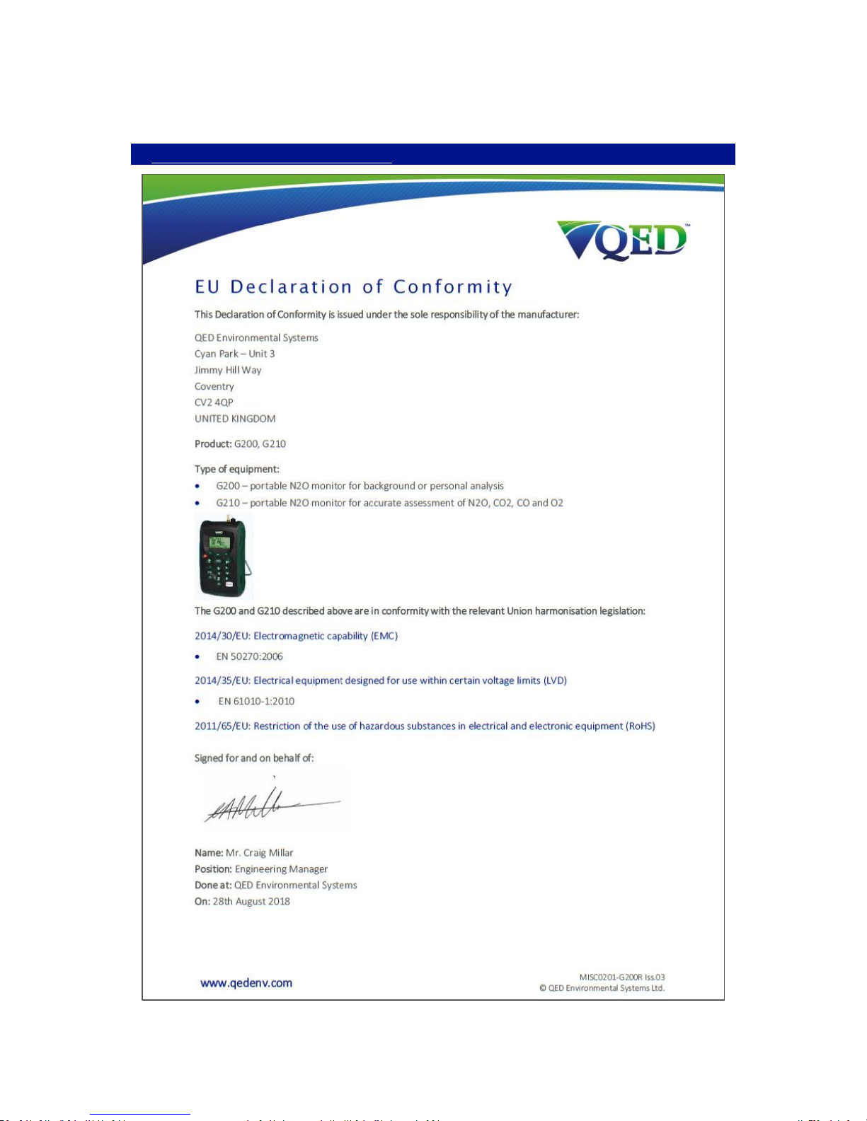
Page 57 of 61
Operating Manual
www.geotechuk.com
OMG200N Iss.04
© QED Environmental Systems Ltd.
G 2 00 R A N G E
EU DECLARATION OF CONFORMITY
Page 58

Page 58 of 61
Operating Manual
www.geotechuk.com
OMG200N Iss.04
© QED Environmental Systems Ltd.
G 2 00 R A N G E
GLOSSARY OF TERMS
Analyser error messages
For a list of standard error codes and for more
information, please refer to section Problem Solving
of the operating manual.
Analyser warnings
There are two types of warning messages displayed;
general warnings that may not necessarily affect the
instrument’s function, for example battery power low,
and operational parameters that could affect the
performance of the analyser, for example CO
2
out of
calibration.
Analyser Data Manager
Analyser Data Manager software enables the operator
to maximise the operation of the instrument.
Instrument readings and event log data can be
downloaded to a PC for further analysis.
Area mode
‘Area’ is the soft-key used to begin operating in area
or room monitoring mode. This mode automatically
stores a rolling average N2O reading every 15 minutes.
G200 only.
Backlight
LED illumination of the LCD display, turns off after 30
seconds, pressing any key relights the display.
Battery charge
A full battery charge will take approximately four
hours.
Calibration
The process that an instrument will undergo to enable
it to measure and display the various parameters in
accordance with the manufacturer’s specification.
Chemical cell
Type of gas detector which can be fitted internally to
the analyser at the time of manufacture.
Clean air purge
Process used to clear out gas from the inlet pipe and
the analyser’s gas sensors prior to taking a new
reading.
CO Carbon monoxide gas.
CO2 Carbon dioxide gas.
Contrast adjustment
Adjustable setting which darkens or lightens the text
displayed on the screen. Typically, this is used to
compensate for different environmental
temperatures. High temperature causes the display to
darken and low temperature causes the display to
lighten.
Data logging
A mode of operation that enables the user to leave
the analyser unattended to take readings
automatically at predetermined times. The reading
interval and pump run-time may be adjusted prior to
Page 59

Page 59 of 61
Operating Manual
www.geotechuk.com
OMG200N Iss.04
© QED Environmental Systems Ltd.
G 2 00 R A N G E
commencing the logging cycle.
Download
Terminology used to describe the transfer of data
from the analyser to a PC via Analyser Data Manager.
Event log
Record of significant events in the life of the analyser.
Used as an aid to monitoring the use of the analyser.
It can also be used as a diagnostic tool if there is a
problem with the analyser. The event log can be
viewed via Analyser Data Manager. It cannot be
viewed on the analyser screen.
Exhaust port
The point at which the gas exits the analyser. This is
located on the top of the analyser. It is threaded to
take an M5 hose-barb to allow an exhaust tube to be
attached if required.
Exhaust tube
Clear plastic tubing used to route gases from the
exhaust port.
Factory settings
Default calibration settings preset at time of factory
calibration.
Firmware
Firmware is the name given to the analyser’s internal
software. This can be programmed using the re-flash
command on Analyser Data Manager. The latest
software release can be downloaded from the QED
website. It is also automatically updated when the
analyser is returned for servicing.
General warnings
Displayed throughout the documentation with a
warning symbol. Warning information may affect the
safety of users.
Inlet port
Port located on the top of the analyser to which the
inlet tube is attached.
Leak mode
‘Leak’ is the soft-key used to begin operating the
instrument in leak detection mode. This extends the
range of the N2O sensor up to 10,000ppm and speeds
up the response time to enable it to indicate the
current level of N2O. G200 only.
LCD display
Liquid Crystal Display. Fitted to the front panel of the
analyser.
Main Read Screen
The main analyser screen for normal operations and
all operations are carried out from this screen.
Memory
The analyser memory should not be used as a
permanent storage medium and data collected should
be transferred using Analyser Data Manager.
N2 Nitrogen gas.
Page 60

Page 60 of 61
Operating Manual
www.geotechuk.com
OMG200N Iss.04
© QED Environmental Systems Ltd.
G 2 00 R A N G E
N2O
Nitrous oxide gas.
O2 Oxygen gas (typically 20.9% in air, measured via
electro-chemical cell).
OEL Occupational Exposure Limits.
Over range codes
Over range codes are errors above the maximum
allowed reading and will be displayed with more than
chevrons (>>.>).
Person mode
‘Person’ is the soft-key used to begin operating in
personal safety monitoring mode. This mode
automatically stores an average N2O reading every 15
minutes. G200 only.
ppm
Parts per million.
Predetermined
Set up prior to use via Analyser Data Manager
software.
Pressure
Maximum input pressure 300mb maximum flow
250ml.
Pump
The device used to transfer a gas sample into the
instrument where that sample is not under pressure.
Select the ‘Pump’ key on the analyser to activate.
Regulator flow
The regulator’s flow is factory set. It only requires a
few turns to open, no adjustment is available.
Sample tube
Tube used to transfer sample gas from the source to
the analyser.
Soda lime CO2 filter kit
Removes CO2 when taking a reading. Must be fitted
on the G200 model.
Span
The point at which the gas analyser is calibrated when
a known concentration of the target gas is present.
TWA
Time Weighted Average.
Under range codes
Under range codes are errors below zero and will be
displayed with less than chevrons (<<.<).
User calibration
Users have the facility to calibrate the analyser
between services. User calibration of the gas analyser
will improve the data accuracy in the range of the
calibration gases used.
Warm-up self-test
Predetermined self-test sequence to test the analyser
functions which takes place after the analyser is
switched on and lasts approximately 30-40 seconds.
Warranty
The instrument is guaranteed against defect in
materials and workmanship for a period of 12 months
Page 61

Page 61 of 61
Operating Manual
www.geotechuk.com
OMG200N Iss.04
© QED Environmental Systems Ltd.
G 2 00 R A N G E
from the date of shipment to the user and is subject
to the recommended service and recalibration
requirements.
Zero
The point at which the gas analyser is calibrated when
there is none of the target gas present.
 Loading...