

Page 1
INSTALLATION MANUAL
HEATING | COOLING | HOT WATER
ASTON SERIES INDOOR SPLIT
Page 2

Page 3

Table of Contents
Model Nomenclature . . . . . . . . . . . . . . . . . . . . . . . . . . . . . . . . . . . . . . . . . . . . . . . . . . . . . . . . . . . . . . 4
General Installation Information . . . . . . . . . . . . . . . . . . . . . . . . . . . . . . . . . . . . . . . . . . . . . . . . . . . . .5-9
Water Quality . . . . . . . . . . . . . . . . . . . . . . . . . . . . . . . . . . . . . . . . . . . . . . . . . . . . . . . . . . . . . . . . . . . . 9
Closed Loop - Ground Source Systems. . . . . . . . . . . . . . . . . . . . . . . . . . . . . . . . . . . . . . . . . . . . .10-11
Open Loop - Well Water Systems . . . . . . . . . . . . . . . . . . . . . . . . . . . . . . . . . . . . . . . . . . . . . . . . . . . 12
Hot Water Generator Connections. . . . . . . . . . . . . . . . . . . . . . . . . . . . . . . . . . . . . . . . . . . . . . . . .13-14
Electrical Connection . . . . . . . . . . . . . . . . . . . . . . . . . . . . . . . . . . . . . . . . . . . . . . . . . . . . . . . . . . .15-16
Electronic Thermostat Installation . . . . . . . . . . . . . . . . . . . . . . . . . . . . . . . . . . . . . . . . . . . . . . . . .16-17
Electrical Data . . . . . . . . . . . . . . . . . . . . . . . . . . . . . . . . . . . . . . . . . . . . . . . . . . . . . . . . . . . . . . . . . . 17
Dimensional Data. . . . . . . . . . . . . . . . . . . . . . . . . . . . . . . . . . . . . . . . . . . . . . . . . . . . . . . . . . . . . . . . 18
Physical Data . . . . . . . . . . . . . . . . . . . . . . . . . . . . . . . . . . . . . . . . . . . . . . . . . . . . . . . . . . . . . . . . . . . 19
Model Nomenclature - Air Handler. . . . . . . . . . . . . . . . . . . . . . . . . . . . . . . . . . . . . . . . . . . . . . . . . . . 20
Coil Data - Air Handler . . . . . . . . . . . . . . . . . . . . . . . . . . . . . . . . . . . . . . . . . . . . . . . . . . . . . . . . . . . . 20
Compatibility Guide - Air Handler. . . . . . . . . . . . . . . . . . . . . . . . . . . . . . . . . . . . . . . . . . . . . . . . . . . . 20
Physical Data - Air Handler. . . . . . . . . . . . . . . . . . . . . . . . . . . . . . . . . . . . . . . . . . . . . . . . . . . . . . . . . 21
Model Nomenclature - Coil. . . . . . . . . . . . . . . . . . . . . . . . . . . . . . . . . . . . . . . . . . . . . . . . . . . . . . . . . 21
Refrigerant Coil Compatibility. . . . . . . . . . . . . . . . . . . . . . . . . . . . . . . . . . . . . . . . . . . . . . . . . . . . . . . 21
The Aurora
Reference Calculations . . . . . . . . . . . . . . . . . . . . . . . . . . . . . . . . . . . . . . . . . . . . . . . . . . . . . . . . . . . 28
Legend . . . . . . . . . . . . . . . . . . . . . . . . . . . . . . . . . . . . . . . . . . . . . . . . . . . . . . . . . . . . . . . . . . . . . . . . 28
Wiring Schematics . . . . . . . . . . . . . . . . . . . . . . . . . . . . . . . . . . . . . . . . . . . . . . . . . . . . . . . . . . . . .29-30
Refrigeration. . . . . . . . . . . . . . . . . . . . . . . . . . . . . . . . . . . . . . . . . . . . . . . . . . . . . . . . . . . . . . . . . .31-33
Line Set Sizes. . . . . . . . . . . . . . . . . . . . . . . . . . . . . . . . . . . . . . . . . . . . . . . . . . . . . . . . . . . . . . . . . . . 33
Pressure/Temperature Conversion Chart for R-410A. . . . . . . . . . . . . . . . . . . . . . . . . . . . . . . . . . . . . 34
Unit Startup. . . . . . . . . . . . . . . . . . . . . . . . . . . . . . . . . . . . . . . . . . . . . . . . . . . . . . . . . . . . . . . . . . .35-37
Operating Parameters . . . . . . . . . . . . . . . . . . . . . . . . . . . . . . . . . . . . . . . . . . . . . . . . . . . . . . . . . .38-39
Pressure Drop . . . . . . . . . . . . . . . . . . . . . . . . . . . . . . . . . . . . . . . . . . . . . . . . . . . . . . . . . . . . . . . . . . 40
Refrigerant Circuit Guideline . . . . . . . . . . . . . . . . . . . . . . . . . . . . . . . . . . . . . . . . . . . . . . . . . . . . . . . 41
Thermistor Resistance . . . . . . . . . . . . . . . . . . . . . . . . . . . . . . . . . . . . . . . . . . . . . . . . . . . . . . . . . . . . 41
Heat of Extraction/Rejection Data . . . . . . . . . . . . . . . . . . . . . . . . . . . . . . . . . . . . . . . . . . . . . . . . . . . 42
Troubleshooting . . . . . . . . . . . . . . . . . . . . . . . . . . . . . . . . . . . . . . . . . . . . . . . . . . . . . . . . . . . . . . .43-45
Preventative Maintenance . . . . . . . . . . . . . . . . . . . . . . . . . . . . . . . . . . . . . . . . . . . . . . . . . . . . . . . . . 46
TM
Control System. . . . . . . . . . . . . . . . . . . . . . . . . . . . . . . . . . . . . . . . . . . . . . . . . . . . .22-27
Replacement Procedures. . . . . . . . . . . . . . . . . . . . . . . . . . . . . . . . . . . . . . . . . . . . . . . . . . . . . . . . . . 46
Service Parts List . . . . . . . . . . . . . . . . . . . . . . . . . . . . . . . . . . . . . . . . . . . . . . . . . . . . . . . . . . . . . . . . 47
Revision Guide. . . . . . . . . . . . . . . . . . . . . . . . . . . . . . . . . . . . . . . . . . . . . . . . . . . . . . . . . . . . . . . . . . 49
Page 4
ASTON INDOOR SPLIT SERIES INSTALLATION MANUAL
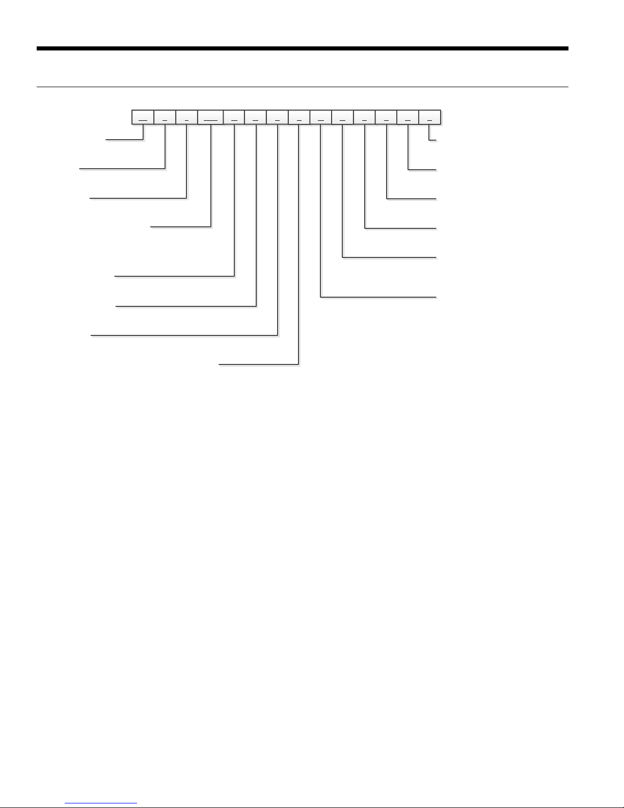
Model Nomenclature
1-2 4 5-7 8 9
3
10 3
Model Type
10 - Aston
Type
3 – Indoor Split
Vintage
* - Factory Use Only
Unit Capacity (MBTUH)
022, 026, 030, 036,
038, 042, 048, 049
060, 064, 070, 072
Future Option
A – None
Future Option
A - None
Voltage
1 – 208-230/60/1
Hot Water Generation & GeoStart Option
0 – No HWG, No GeoStart
1 – HWG with Factory Installed Pump, No GeoStart
3 – No HWG, GeoStart
4 – HWG with Factory Installed Pump, GeoStart
* 049 A A 1 0 A C 013015A160
®
10 11 12 14
17
Future Option
0 - Standard
Controls
A – Aurora
Future Option
0 – Standard
Future Option
0 – Standard
Coax Option
C – Copper
N – CuproNickel
Future Option
A – None
Rev.: 08 October 2013D
TM
Base Control
4
Page 5

ASTON INDOOR SPLIT SERIES INSTALLATION MANUAL
General Installation Information
Safety Considerations Duct System
WARNING: Before performing service or maintenance
operations on a system, turn off main power switches
to the indoor unit. If applicable, turn off the accessory
heater power switch. Electrical shock could cause
personal injury.
Installing and servicing heating and air conditioning equipment can
be hazardous due to system pressure and electrical components.
Only trained and qualified service personnel should install, repair or
service heating and air conditioning equipment. Untrained personnel
can perform the basic maintenance functions of cleaning coils
and cleaning and replacing filters. All other operations should be
performed by trained service personnel. When working on heating
and air conditioning equipment, observe precautions in the literature,
tags and labels attached to the unit and other safety precautions that
may apply, such as the following safety measures:
• Follow all safety codes.
• Wear safety glasses and work gloves.
• Use a quenching cloth for brazing operations.
• Have a fire extinguisher available for all brazing operations.
Moving and Storage
Move units in the normal “up” orientation. Units may be moved and
stored per the information on the packaging. Do not stack more
than three units in total height. Do not attempt to move units while
stacked. When the equipment is received, all items should be
carefully checked against the bill of lading to be sure all crates and
cartons have been received. Examine units for shipping damage,
removing the units from the packaging if necessary. Units in
question should also be internally inspected. If any damage is noted,
the carrier should make the proper notation on the delivery receipt,
acknowledging the damage.
Unit Location
NOTE: Prior to setting the unit in place, remove and discard the
compressor shipping bolt located at the front of the compressor
mounting bracket.
Locate the unit in an indoor area that allows for easy removal of
the access panels. Location should have enough space for service
personnel to perform maintenance or repair. Provide sufficient room
to make water, electrical and refrigerant line connections. Any
access panel screws that would be difficult to remove after the unit
is installed should be removed prior to setting the unit. Care should
be taken when units are located in unconditioned spaces to prevent
damage from frozen water lines and excessive heat that could
damage electrical components.
Air Coil Location
Refer to the air handler manufacturer’s instructions for the blower coil
unit for details on installing the air handling portion of the system.
Condensate Drain
Follow the blower coil manufacturer’s instructions.
All blower coil units/air coils must be installed as specified by the
manufacturer’s installation instructions; however, the following
recommendations should be considered to minimize noise and
service problems.
An air filter must always be installed upstream of the air coil on
the return air side of the air handler or furnace. If there is limited
access to the filter rack for normal maintenance, it is suggested
that a return air filter grill be installed. Be sure that the return duct
is properly installed and free of leaks to prevent dirt and debris
from bypassing the filter and plugging the air coil.
In applications using galvanized metal ductwork, a flexible duct
connector is recommended on both the supply and return air
plenums to minimize vibration from the blower. To maximize sound
attenuation of the unit blower, the supply and return plenums
should include an internal duct liner of 1-inch thick glass fiber or
be constructed of ductboard. Insulation is usually not installed in
the supply branch ducts. Ducts in unconditioned areas should be
wrapped with a minimum of 1-inch duct insulation. Application of
the unit to uninsulated ductwork in an unconditioned space is not
recommended as the unit’s performance will be adversely affected.
If the air handler is connected to existing ductwork, a previous
check should have been made to assure that the duct system has
the capacity to handle the air required for the unit application. If
ducting is too small, as in replacement of heating only systems,
larger ductwork should be installed. All existing ductwork should be
checked for leaks and repairs made accordingly. The duct systems
and diffusers should be sized to handle the design airflow quietly.
If air noise or excessive airflow is a problem, the blower speed can
be changed to a lower speed to reduce airflow. This will reduce the
performance of the unit slightly in heating; however, it will increase
the temperature rise across the air coil. Airflow must still meet
minimum requirements.
Equipment Selection
The following guidelines should be used when mating a indoor split
to an air handler/coil.
• Select R-410A components only .
• Select 13 SEER or higher air handler/coil.
• Match the air handler to the air handler coil data table.
• Indoor matching adjustable TXV should be used with any air
handler/coil. Fixed orifice or cap tube systems should not be used.
Utilizing Existing Coil or Air Handler
It is recommended that a new R-410A air handler be installed with a
indoor split considering the long term benefits of reliability, warranty,
etc. versus the short term installation cost savings. However, the
existing air handler may be retained provided the following:
• Coil currently is R-410A rated
• Coil uses a TXV. No capillary or fixed orifice systems should
be used
• A life expectancy of more than 7 years remaining for the air
handler and components
• Flush air coil and line set
5
Page 6
ASTON INDOOR SPLIT SERIES INSTALLATION MANUAL
General Installation Information cont.
When utilizing the existing air coil or line set, only flushing
compounds that vaporize should be used; which means they are
packaged in a pressurized disposable cylinder. It is preferable
to use a flushing agent that removes oil, water, and acid, plus, is
biodegradeable and non-toxic. The flushing agent should be safe to
use with both HCFC and HFC refrigerants. Once a flushing agent
has been selected, follow the instructions provided with the product.
The first step should be purging the lines or air coil with nitrogen.
Purging with nitrogen first will remove some of the particulate and
residual oil which will allow the flushing agent to work better. Never
blow the flushing agent through a compressor, filter drier, or txv as it
will cause the components to fail.
When flushing is complete and the final system is assembled, an
acid check should be preformed on the system. Acid test kits are
available from most HVACR distributors.
Connection to Air Coil
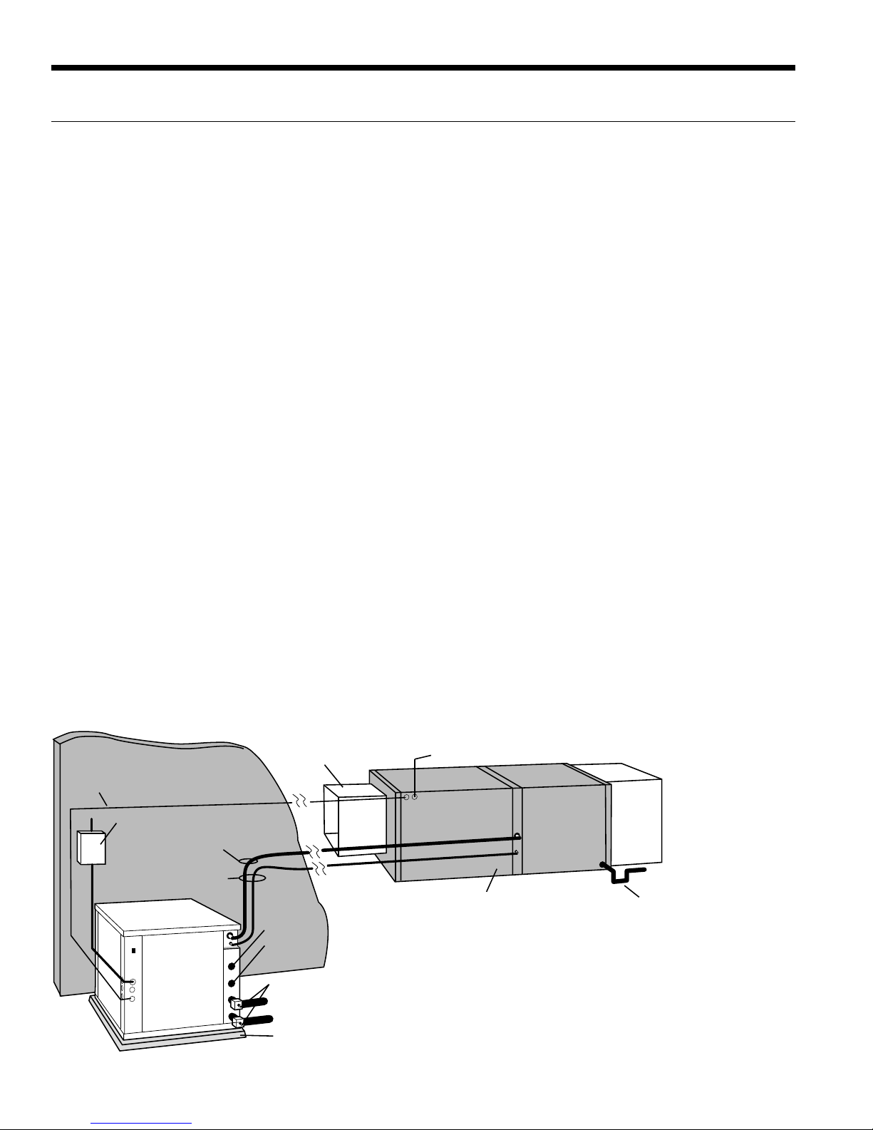
Figures 1 and 2 illustrate typical indoor split installations. Reference
the Line Set Sizes table for typical line set diameters and maximum
length. Line sets over 60 feet are not recommended. Longer line
sets will significantly reduce capacity and efficiency of the system
as well as adversely effect the system reliability due to poor oil
return. If the line set is kinked or deformed and cannot be reformed,
the bad section of pipe should be replaced. A restricted line set will
affect unit performance. As in all R-410A equipment, a reversible
liquid line filter drier is required to insure all moisture is removed
from the system. This drier should be replaced whenever “breaking
into” the system for service. All line sets should be insulated with
a minimum of 1/2 in. closed cell insulation. All exterior insulation
should be painted with UV resistant paint or covering to ensure long
insulation life.
Air Handler Installation
Air handlers used with dual capacity units must be capable
of operating with a minimum of 2 blower speeds. Refer to the
manufacturer’s instructions for the blower coil unit for details on
installing the air handling portion of the system. All blower coil
units/air coils must be installed as specified by the manufacturer’s
installations instructions. However, the following recommendations
should be considered to minimize noise and service problems.
An air filter must always be installed upstream of the air coil on the
return air side of the air handler or furnace. If there is limited access
to the filter rack for normal maintenance, it is suggested that a return
air filter grille be installed. Be sure that the return duct is properly
installed and free of leaks to prevent dirt and debris from bypassing
the filter and plugging the air coil.
Ensure that the line set size is appropriate to the capacity of the
unit (refer to Line Set Sizes table). Line sets should be routed as
directly as possible, avoiding unnecessary bends or turns. All wall
penetrations should be sealed properly. Line set should not come
into direct contact with water pipes, floor joists, wall studs, duct
work, floors, walls and brick. Line set should not be suspended
from joists or studs with a rigid wire or strap which comes into direct
contact with the tubing. Wide hanger strips which conform to the
shape of the tubing are recommended. Isolate hanger straps from
line set insulation by using metal sleeves bent to conform to the
shape of insulation. Line set insulation should be pliable, and should
completely surround the refrigerant line.
NOTES: Improper installation of equipment may result in
undesirable noise levels in the living areas.
Figure 1: Typical Split System Application with Remote Blower Coil
Thermostat Wire
From Air Handler
Disconnect
Insulated Suction Line
Lineset To Air Handler
DHW Out
DHW In
P/T Plugs
Water Out
Water In
Vibration Absorbing Pad or Air Pad
Supply
Duct
Wire To
Thermostat
Remote Air Handler
(Maximum Recommended Distance is
60' Between Units)
6
Return
Duct
To D r a in
Condensate Drain
(must be trapped)
Page 7
General Installation Information cont.
ASTON INDOOR SPLIT SERIES INSTALLATION MANUAL
Dual Fuel Systems
Indoor split units can be connected to fossil fuel furnaces that
include an A-coil or slab coil. Dual fuel installations utilize the
geothermal heat pump for heating until the point that auxiliary
heat is called for on the thermostat. At that point, the furnace will
be enabled and the heat pump will be disabled. The geothermal
heat pump provides air conditioning through the furnace’s
refrigerant coils.
In add-on indoor split applications, the coil should be located in
the supply side of the furnace to avoid condensation damage
to the furnace heat exchanger. A high temperature limit should
be installed upstream of the coil to de-energize the compressor
whenever the furnace is operating. Without this switch, the
indoor split will trip out on high pressure. A dual fuel thermostat
can remove the Y1 and Y2 calls when a W call is energized to
allow gas furnace backup on a indoor split application. Refer to
thermostat wiring diagram for details.
Refer to the furnace manufacturer’s installation manual for
the furnace installation, wiring and coil insertion. A Dual Fuel
thermostat, a field-installed SPST relay or dual capacity
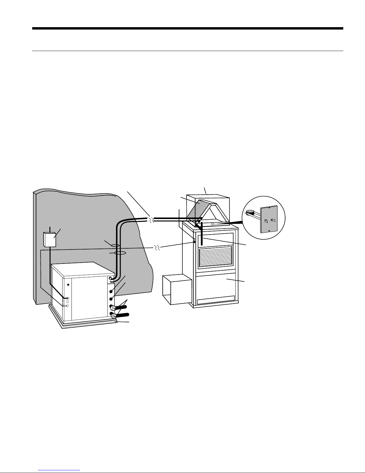
auxiliary heat relay is required. See Figure 2 for typical Dual
Fuel application.
Figure 2: Typical Split System Heat Pump Coil Add-On Fossil Fuel Furnace
Maximum Recommended Distance
Disconnect
Insulated Suction Line
is 60' Between Units
Wire To
Thermostat
Thermostat
Wire From
Air Handler
"A" or
Slab Coil
Supply Duct
Lineset To Air Handler
Air Temperature Limit Switch to prevent compressor operation
when entering air is greater than
90°F.
Condensate
Drain
(must be trapped)
DHW Out
DHW In
Return
P/T Plugs
Duct
Water Out
Water In
Vibration Absorbing Pad or Air Pad
Up-Flow
Fossil Fuel
Furnace
7
Page 8
ASTON INDOOR SPLIT SERIES INSTALLATION MANUAL
General Installation Information cont.
Water Piping
The proper water flow must be provided to each unit whenever the
unit operates. To assure proper flow, use pressure/temperature
ports to determine the flow rate. These ports should be located at
the supply and return water connections on the unit. The proper
flow rate cannot be accurately set without measuring the water
pressure drop through the refrigerant-to-water heat exchanger.
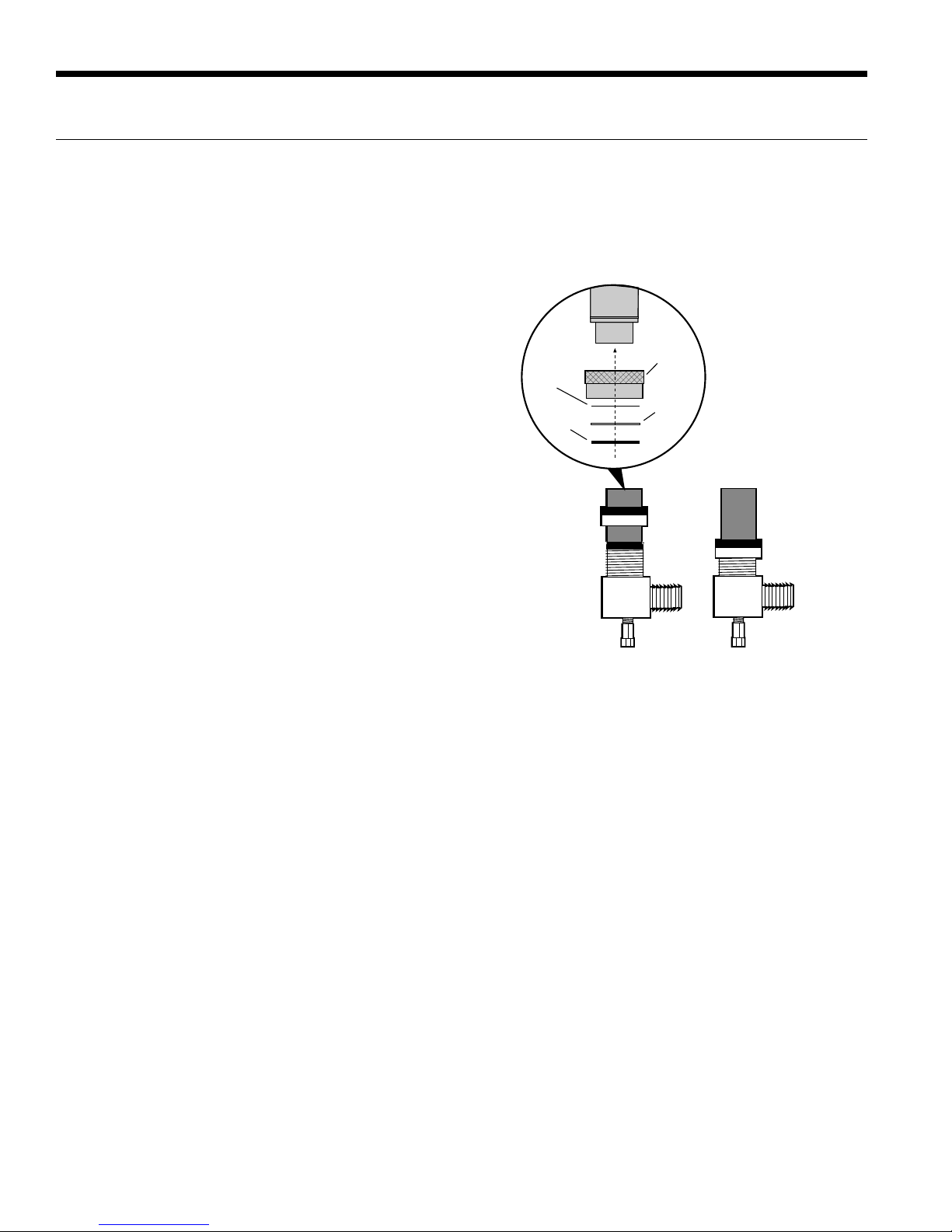
All source water connections on residential units are swivel piping
fittings (see Figure 3) that accept 1 in. male pipe threads (MPT).
The swivel connector has a rubber gasket seal similar to a rubber
hose gasket, which when mated to the flush end of any 1 in.
threaded pipe provides a leak-free seal without the need for thread
sealing tape or compound. Check to ensure that the rubber seal
is in the swivel connector prior to attempting any connection. The
rubber seals are shipped attached to the waterline. To make the
connection to a ground loop system, mate the brass connector
(supplied in CK4L connector kit) against the rubber gasket in the
swivel connector and thread the female locking ring onto the pipe
threads, while maintaining the brass connector in the desired
direction. Tighten the connectors by hand, then gently snug the
fitting with pliers to provide a leak-proof joint. When connecting to
an open loop (ground water) system, thread the 1 in. MPT fitting
(SCH80 PVC or copper) into the swivel connector and tighten in
the same manner as noted above. The open and closed loop piping
system should include pressure/temperature taps for serviceability.
Never use flexible hoses smaller than 1 in. inside diameter on the
unit. Limit hose length to 10 ft. per connection. Check carefully for
water leaks.
Figure 3: Swivel Connections
(Residential Units)
Stainless
Steel
Snap Ring
Gasket
Material
Locking
Ring
Gasket
Support
Sleeve
8
Page 9
ASTON INDOOR SPLIT SERIES INSTALLATION MANUAL
General Installation Information cont.
Water Quality
In ground water situations where scaling could be heavy or where
biological growth such as iron bacteria will be present, a closed
loop system is recommended. The heat exchanger coils in ground
water systems may, over a period of time, lose heat exchange
capabilities due to a buildup of mineral deposits inside. These
can be cleaned, but only by a qualified service mechanic, as
special solutions and pumping equipment are required. Hot water
generator coils can likewise become scaled and possibly plugged.
In areas with extremely hard water, the owner should be informed
that the heat exchanger may require occasional flushing.
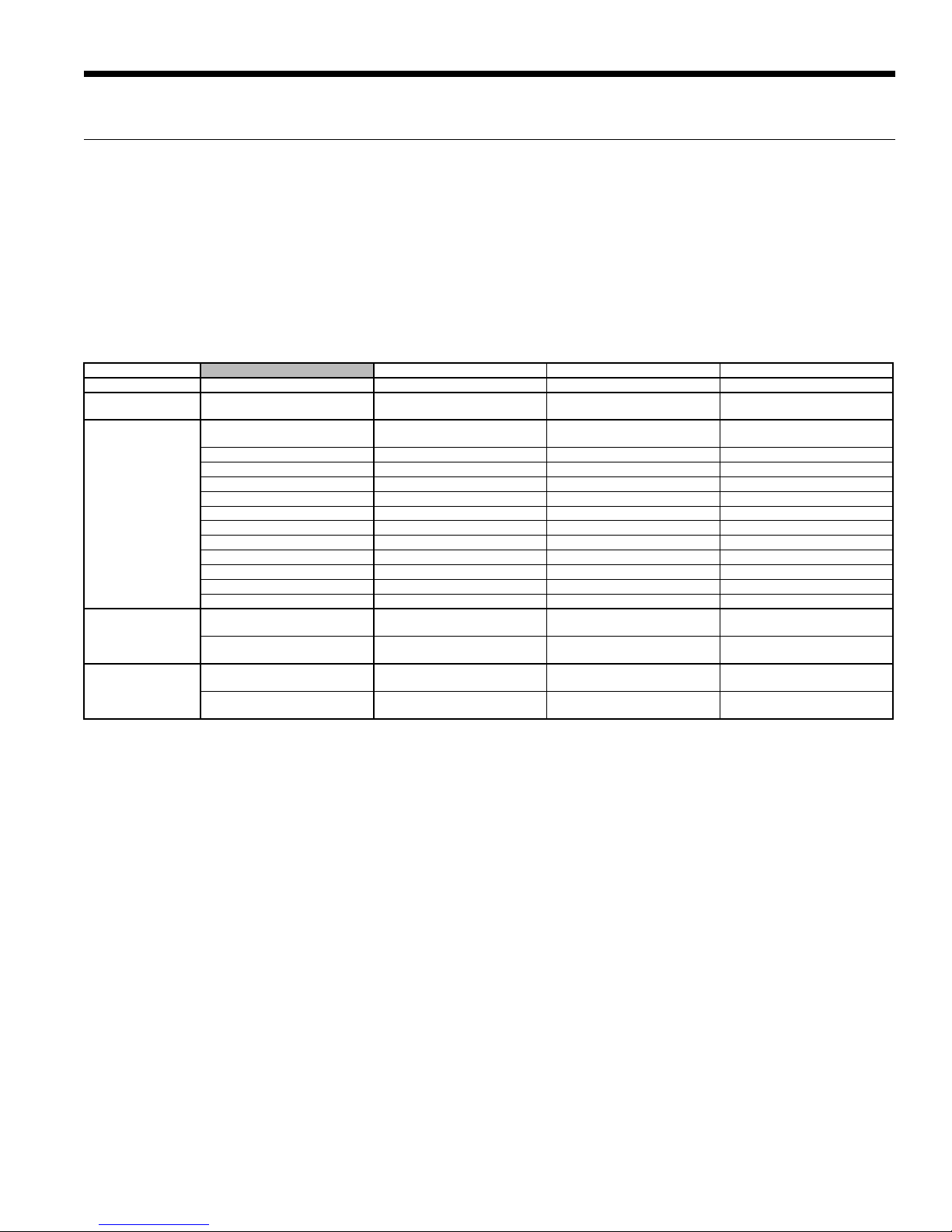
Material Copper 90/10 Cupronickel 316 Stainless Steel
pH Acidity/Alkalinity 7 - 9 7 - 9 7 - 9
Scaling
Corrosion
Iron Fouling
(Biological Growth)
Erosion
NOTES: Grains = ppm divided by 17
mg/L is equivalent to ppm
Calcium and
Magnesium Carbonate
Hydrogen Sulfide
Sulfates Less than 125 ppm Less than 125 ppm Less than 200 ppm
Chlorine Less than 0.5 ppm Less than 0.5 ppm Less than 0.5 ppm
Chlorides Less than 20 ppm Less than 125 ppm Less than 300 ppm
Carbon Dioxide Less than 50 ppm 10 - 50 ppm 10 - 50 ppm
Ammonia Less than 2 ppm Less than 2 ppm Less than 20 ppm
Ammonia Chloride Less than 0.5 ppm Less than 0.5 ppm Less than 0.5 ppm
Ammonia Nitrate Less than 0.5 ppm Less than 0.5 ppm Less than 0.5 ppm
Ammonia Hydroxide Less than 0.5 ppm Less than 0.5 ppm Less than 0.5 ppm
Ammonia Sulfate Less than 0.5 ppm Less than 0.5 ppm Less than 0.5 ppm
Total Dissolved Solids (TDS) Less than 1000 ppm 1000 - 1500 ppm 1000 - 1500 ppm
LSI Index +0.5 to -0.5 +0.5 to -0.5 +0.5 to -0.5
2
Iron, FE
Bacterial Iron Potential
+ (Ferrous)
Iron Oxide
Suspended Solids
Threshold Velocity
(Fresh Water)
(Total Hardness)
less than 350 ppm
Less than 0.5 ppm (rotten egg
smell appears at 0.5 ppm)
< 0.2 ppm < 0.2 ppm < 0.2 ppm
Less than 1 ppm, above this level
deposition will occur
Less than 10 ppm and filtered for
max. of 600 micron size
< 6 ft/sec < 6 ft/sec < 6 ft/sec
Units with cupronickel heat exchangers are recommended for
open loop applications due to the increased resistance to build-up
and corrosion, along with reduced wear caused by acid cleaning.
Failure to adhere to the guidelines in the water quality table could
result in the loss of warranty.
(Total Hardness)
less than 350 ppm
10 - 50 ppm Less than 1 ppm
Less than 1 ppm, above this level
deposition will occur
Less than 10 ppm and filtered for
max. of 600 micron size
(Total Hardness)
less than 350 ppm
Less than 1 ppm, above this level
deposition will occur
Less than 10 ppm and filtered for
max. of 600 micron size
2/22/12
Low Water Coil Limit
Set the freeze sensing switch SW2-1 on the Aurora Base Control
(ABC) printed circuit board for applications using a closed loop
antifreeze solution to “LOOP” (15°F). On applications using an
open loop/ground water system (or closed loop no antifreeze), set
this dip switch to “WELL” (30°F), the factory default setting. (Refer
to the DIP Switch Settings table in the Aurora Control section.)
9
Page 10
ASTON INDOOR SPLIT SERIES INSTALLATION MANUAL
Closed Loop - Ground Source Systems
NOTE: For closed loop systems with antifreeze protection, set
SW2-1 to the “LOOP” (15°F) position. (Refer to the DIP Switch Settings table in the Aurora Control section.)
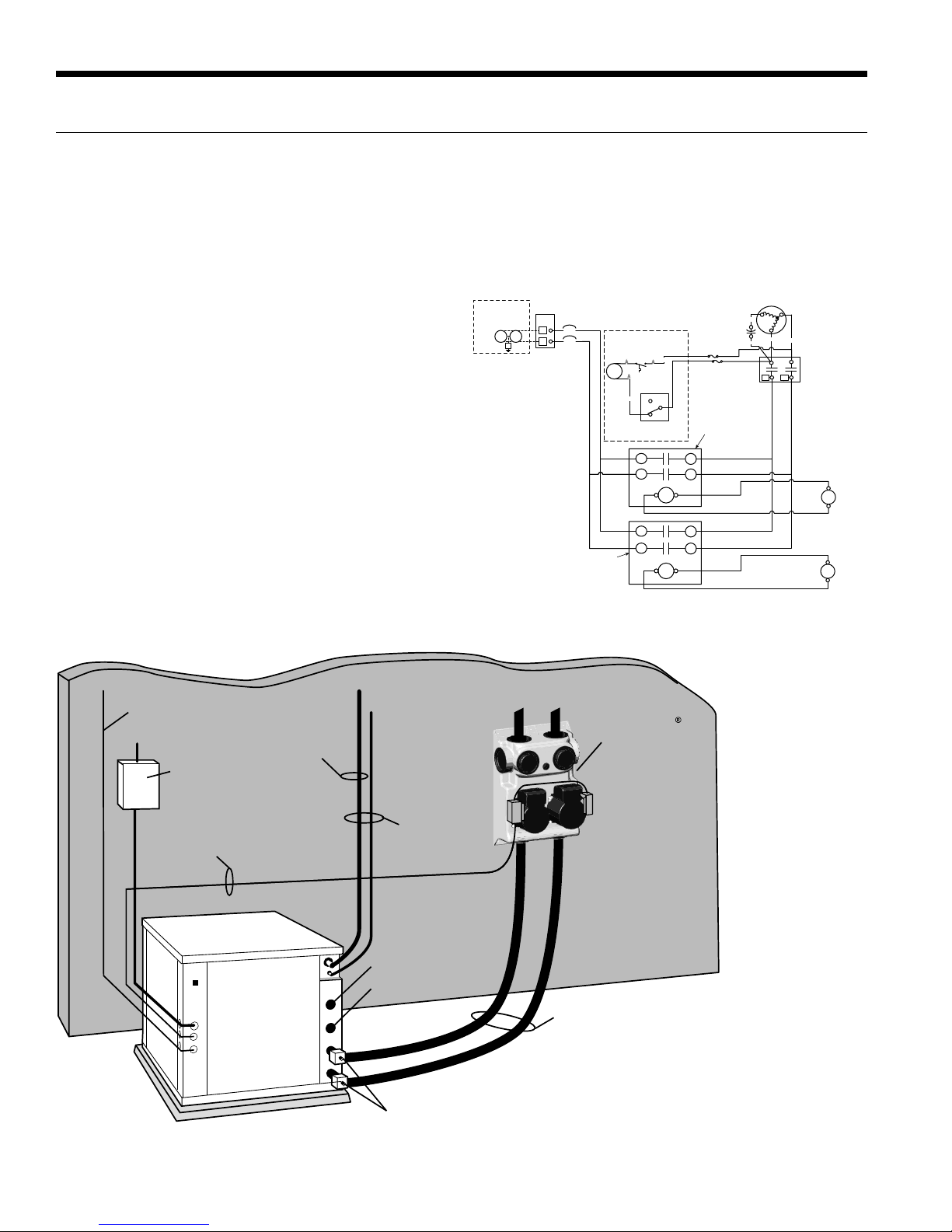
Once piping is completed between the unit, pumps and the ground
loop (see figure below), final purging and charging of the loop is
required. A flush cart (or a 1.5 HP pump minimum) is needed to
achieve adequate flow velocity in the loop to purge air and dirt particles from the loop itself. Antifreeze solution is used in most areas
to prevent freezing. Flush the system adequately to remove as
much air as possible then pressurize the loop to a static pressure of
40-50 psi (summer) or 50-75 psi (winter). This is normally adequate
for good system operation. Loop static pressure will fluctuate with
the seasons. Pressures will be higher in the winter months than
during the cooling season. This fluctuation is normal and should be
considered when initially charging the system.
After pressurization, be sure to turn the venting (burping) screw in
the center of the pump two (2) turns open (water will drip out), wait
until all air is purged from the pump, then tighten the plug. Ensure
that the loop pumps provide adequate flow through the unit(s) by
checking the pressure drop across the heat exchanger and comparing it to the unit capacity data in this catalog. 2.5 to 3 gpm of flow per
ton of cooling capacity is recommended in earth loop applications.
Multiple Units on One Flow Center
When two units are connected to one loop pumping system, pump
control is achieved by following Figure 5. Installer will be required to
supply fuses, two relays, and wiring.
Figure 5: Primary/Secondary Wiring
Ext Pump
1/2 hp Total
208-230/60/1
Pump
Pump
G
Circuit
Breaker
PB1
1
1
1
2
2
Circuit
Breaker
Field Supplied
Relay for Heat
5A
5A
Pump 2
Hot Water
Limit Switch
130°F
HWG
Pump
Cabinet
HW Switch
Blue
Optional Internal
HWG Pump
Cap
Field Supplied
Fuses 5A
Purple
3
2
1
Field Supplied
Relay for Heat
Pump 1
Blue
Tan(6)
Red
T2
L2
Compressor
CRS
Black
T1
CC
L1
Contactor Coil
Contactor Coil
Heat Pump 1
Heat Pump 2
Figure 4: Typical Split System Application Closed Loop - Earth Coupled
Thermostat Wire
From Air Handler
Insulated
Disconnect
Lineset
Flow Center
Electrical Supply
To Air
Handler
DHW Out
DHW In
Water Out
To Loop
GeoLink
Flow Center
Rubber Hose Connector
Kit CK4L or CK4S
Vibration Absorbing Pad or Air Pad
Water In
P/T Plugs
NOTE: Additional information can be found in Flow Center
installation manual and Flush Cart manual.
10
Page 11
Open Loop - Well Water Systems
ASTON INDOOR SPLIT SERIES INSTALLATION MANUAL
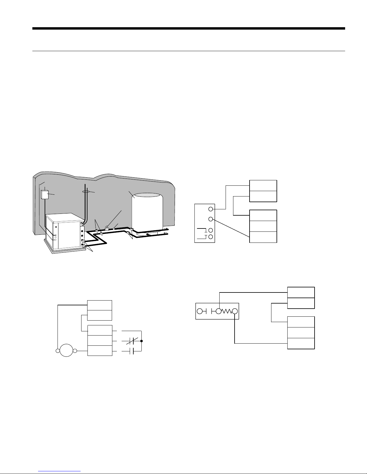
Typical open loop piping is shown below. Always maintain
water pressure in the heat exchanger by placing water control
valves at the outlet of the unit to prevent mineral precipitation.
Use a closed, bladder-type expansion tank to minimize mineral
formation due to air exposure. Ensure proper water flow through
the unit by checking pressure drop across the heat exchanger
and comparing it to the figures in unit capacity data tables in the
specification catalog. 1.5-2 gpm of flow per ton of cooling capacity
is recommended in open loop applications.
Discharge water from the unit is not contaminated in any manner
and can be disposed of in various ways, depending on local codes,
Figure 6: Typical Split System Application Open Loop Well Water
Thermostat Wire
From Air Handler
Disconnect
Vibration Absorbing Pad or Air Pad
Lineset
T o Air Handler
Boiler Drains for
System Flushing
P/T Plugs
Rubber Bladder
Pressure Tank
Water Solenoid
Control Valve
Flow
Regulator
Shut-Off Valves
Water Out
Water In
From W ell
Figure 7a: Open Loop Solenoid Valve Connection Option
Typical quick operating external 24V water solenoid valve
(type PPV100 or BPV100) wiring.
i.e. recharge well, storm sewer, drain field, adjacent stream or
pond, etc. Most local codes forbid the use of sanitary sewer for
disposal. Consult your local building and zoning departments to
assure compliance in your area.
NOTE: For open loop/groundwater systems or systems that do not
contain an antifreeze solution, set SW2-Switch #1 to the “WELL”
(30°F) position. (Refer to the DIP Switch Settings table in the
Aurora Control section.) Slow opening/closing solenoid valves
(type V or VM) are recommended to eliminate water hammer.
Figure 7b: Open Loop Solenoid Valve Connection Option
Typical slow operating external 24V water solenoid valve
(type V) wiring.
C
R
C
W/Y
Acc Com
ACC NC
Acc NO
V Valve ABC Board
Figure 7c: Open Loop Solenoid Valve Connection Option
Typical slow operating external 24V water solenoid valve
(type VM) wiring.
C
C
P1
R
SV
Solenoid
Acc Com
Acc NC
Acc NO
ABC Board
1
2
3
Valve
NOTE: SW2-4 and SW2-5 should be “OFF” to cycle with
the compressor.
P2
R
VM Valve
Acc Com
ACC NC
Acc NO
ABC Board
NOTE: SW2-4 should be “ON” and SW2-5 should be “OFF” when
using a slow opening (V or VM) water valve.
11
Page 12
ASTON INDOOR SPLIT SERIES INSTALLATION MANUAL
Hot Water Generator Connections
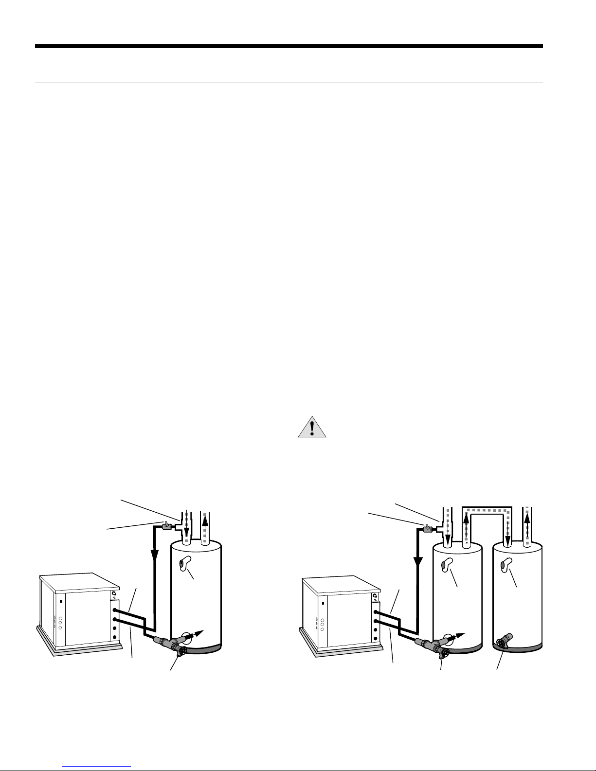
The heat reclaiming hot water generator coil is vented double-wall
copper construction and is suitable for potable water. To maximize
the benefits of the hot water generator a minimum 50-gallon water
heater is recommended. For higher demand applications, use an
80-gallon water heater or two 50-gallon water heaters connected
in a series as shown below. A geo storage tank should not be used
in this application unless it is plumbed in a series with an electric
water heater. The geo storage tank is equipped with a single 4500
Watt element and will not be able to provide adequate water heating
if used as a standalone water heater. Electric water heaters are
recommended. Make sure all local electrical and plumbing codes
are followed when installing a hot water generator. Residential units
with hot water generators contain an internal circulator and fittings. A
water softener is recommended for hard water applications (greater
than 10 grains or 170 ppm total hardness).
Water Tank Preparation
To install a unit with hot water generator, follow these
installation guidelines.
1. Turn off the power to the water heater.
2. Attach a water hose to the water tank drain connection and
run the other end of the hose to an open drain or outdoors.
3. Close the cold water inlet valve to the water heater tank.
4. Drain the tank by opening the valve on the bottom of the tank,
then open the pressure relief valve or hot water faucet.
Figure 8: Typical Hot Water Generator Installation
Ý[Ý[ÝWHH
Venting Waste Valve
or Vent Coupling
HWG
Water Out
Cold
Water In
P/T Relief
Water Out
Valv e
Hot
5. Flush the tank by opening the cold water inlet valve to the
water heater to free the tank of sediments. Close when
draining water is clear.
6. Disconnect the garden hose and remove the drain valve from
the water heater.
7. Refer to Plumbing Installation and Hot Water
Generator Startup.
CAUTION: Elements will burn out if energized dry.
Figure 9: Hot Water Generator Installation in Preheat Tank
Hot
Water Out
P/T Relief
Valve
Venting W a ste Valve
or Vent Coupling
Ý[Ý[ÝWHH
HWG
Water Out
Cold
Water In
P/T Relief
Valve
HWG
Water In
Drain Valve
In
HWG
Water In
Drain Valve Drain Valve
In
12
Page 13
Hot Water Generator Connections cont.
ASTON INDOOR SPLIT SERIES INSTALLATION MANUAL
Plumbing Installation
1. Inspect the dip tube in the water heater cold inlet for a check
valve. If a check valve is present it must be removed or
damage to the hot water generator circulator will occur.
2. Remove drain valve and fitting.
3. Thread the 3/4-inch NPT x 3-1/2-inch brass nipple into the
water heater drain port.
4. Attach the center port of the 3/4-inch FPT tee to the opposite
end of the brass nipple.
5. Attach the 1/2-inch copper to 3/4-inch NPT adaptor to the side
of the tee closest to the unit.
6. Install the drain valve on the tee opposite the adaptor.
7. Run interconnecting tubing from the tee to hot water generator
water out.
8. Cut the cold water “IN” line going to the water heater.
9.
Insert the reducing solder tee in line with cold water “IN” line
as shown.
10.
Run interconnecting copper tubing between the unit hot water
generator water “IN” and the tee (1/2-inch nominal). The
recommended maximum distance is 50 feet.
11.
To prevent air entrapment in the system, install a vent coupling
at the highest point of the interconnecting lines.
12. Insulate all exposed surfaces of both connecting water lines
with 3/8-inch wall closed cell insulation.
NOTE: All plumbing and piping connections must comply with local
plumbing codes.
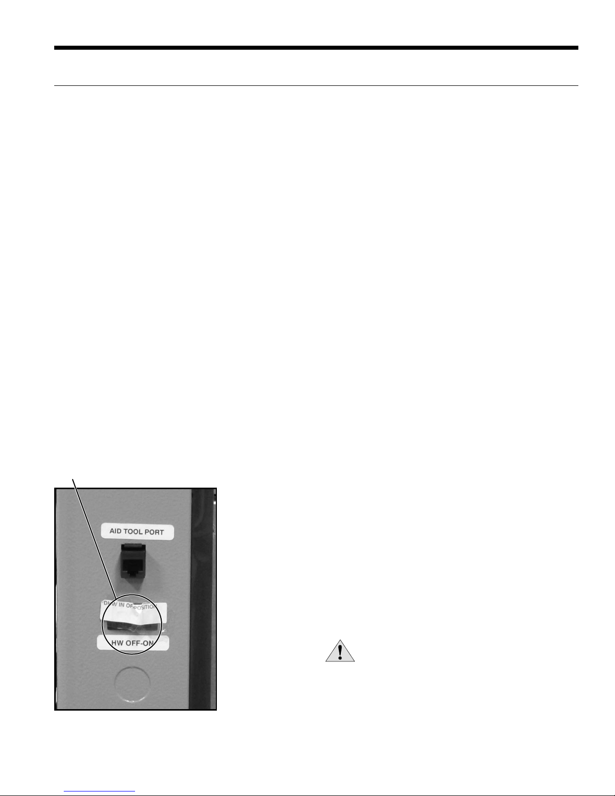
Hot Water Generator Switch
The hot water generator switch is taped in the disabled position
at the factory.
Hot Water Generator Startup
1. Turn the hot water generator switch to the “ON” position. The hot
water generator switch will allow the hot water generator pump to
be enabled or disabled by the service technician or homeowner.
2. Close the drain valve to the water heater.
3. Open the cold water supply to the tank.
4. Open a hot water faucet in the building to bleed air from the
system. Close when full.
5. Open the pressure relief valve to bleed any remaining air from
the tank, then close.
6. If so equipped, turn the venting (burping) screw in the center
of the pump two (2) turns open (water will drip out), wait until
all air is purged from the pump, then tighten the plug. Use vent
couplings to bleed air from the lines.
7. Carefully inspect all plumbing for water leaks and correct
as required.
8. Before restoring electrical supply to the water heater, adjust the
temperature setting on the tank.
• On tanks with both upper and lower elements, the
lower element should be turned down to the lowest
setting, approximately 100°F. The upper element
should be adjusted to 120°F to 130°F. Depending upon
the specific needs of the customer, you may want to
adjust the upper element differently.
• On tanks with a single element, lower the thermostat
setting to 120°F.
9. After the thermostat(s) is adjusted, replace the access cover
and restore electrical supply to the water heater.
10. Make sure that any valves in the hot water generator water
circulating circuit are open.
11. Turn on the unit to first stage heating.
12. The hot water generator pump should be running. When
the pump is first started, turn the venting (burping) screw (if
equipped) in the center of the pump two (2) turns open until
water dribbles out, then replace. Allow the pump to run for at
least five minutes to ensure that water has filled the circulator
properly. Be sure the switch for the hot water generator pump
switch is “ON”.
13. The temperature difference between the water entering and
leaving the hot water generator should be 5°F to 15°F. The water
flow should be approximately 0.4 gpm per ton of nominal cooling.
14. Allow the unit to heat water for 15 to 20 minutes to be sure
operation is normal.
CAUTION: Never operate the HWG circulating pump
while dry. If the unit is placed in operation before
the hot water generator piping is connected, be sure
that the pump switch is set to the OFF position.
13
Page 14
ASTON INDOOR SPLIT SERIES INSTALLATION MANUAL
Electrical Connections
General
Be sure the available power is the same voltage and phase as that
shown on the unit serial plate. Line and low voltage wiring must be
done in accordance with local codes or the National Electric Code,
whichever is applicable.
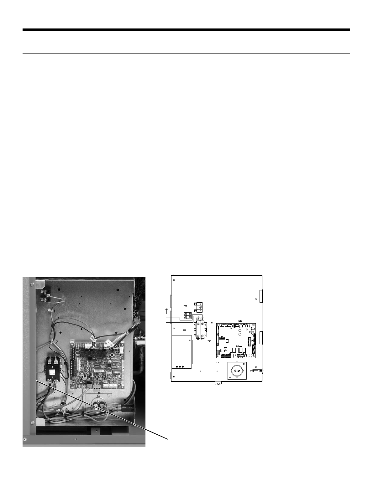
Unit Power Connection
Connect the incoming line voltage wires to L1 and L2 of the
contactor as shown in Figure 10B for single-phase unit. Consult
the Unit Electrical Data in this manual for correct fuse sizes.
Open front access panel. Insert power wires through knockouts
on the left side of cabinet (Figure 10A). Route wires through left
side of control box and connect to contactor and ground (Figure
10B). Close control box and replace grounding fastener before unit
start-up.
Accessory Relay
A set of “dry” contacts has been provided to control accessory
devices, such as water solenoid valves on open loop installations,
electronic air cleaners, humidifiers, etc. This relay contact should
be used only with 24 volt signals and not line voltage power. The
relay has both normally open and normally closed contacts and
can operate with either the fan or the compressor. Use DIP switch
SW2-4 and 5 to cycle the relay with blower, compressor, or control
a slow opening water valve. The relay contacts are available on
terminals #2 and #3 of P2.
When powering high VA draw components such as electronic air
cleaners or VM type open loop water valves, R should be taken
‘pre-fuse’ from the ‘R’ quick connect on the ABC board and not the
‘post-fuse’ ‘R’ terminal on the thermostat connection. If not, blown
ABC fuses might result.
208 Volt Operation
All 208/230 units are factory wired for 230 volt operation. For
208 volt operation, the red and blue transformer wires must be
switched on terminal strip PB2.
Figure 10A:
Wire access
Figure 10B:
Line Voltage 208-230/60/1 control box
1
PB1
2
L2
L1
T1T2
Wire Insert
Location
14
Page 15
Electrical Connections cont.
ASTON INDOOR SPLIT SERIES INSTALLATION MANUAL
Pump Power Wiring
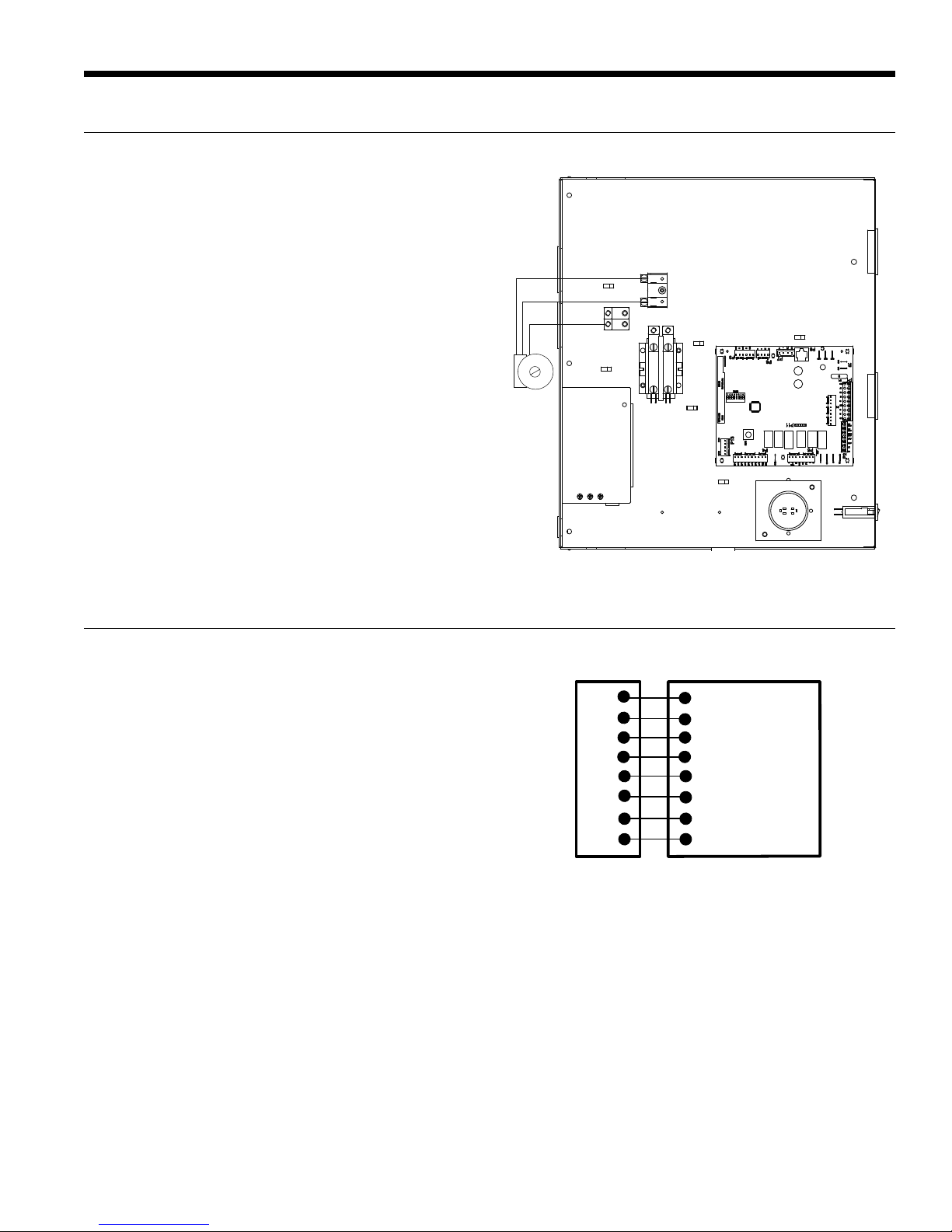
See Figure 11 for electrical connections from control box
to pumps.
FC1/FC2 style flow centers with fixed speed pumps connect to
PB1 in the control box.
Figure 11: Pump Wiring 208-230/60/1
PB1
External
Loop Pump(s)
208-230/60/1
1/2 hp Max
CB
Electronic Thermostat Installation
Position the thermostat subbase against the wall so that it is
level and the thermostat wires protrude through the middle of
the subbase. Mark the position of the subbase mounting holes
and drill holes with a 3/16-inch bit. Install supplied anchors and
secure base to the wall. Thermostat wire must be 8-conductor
(4 or 5 counductor for communicating thermostats), 20-AWG
(minimum) wire. Strip the wires back 1/4-inch (longer strip
lengths may cause shorts) and insert the thermostat wires into
the connector as shown. Tighten the screws to ensure secure
connections. The thermostat has the same type connectors,
requiring the same wiring. See instructions enclosed in the
thermostat for detailed installation and operation information.
NOTE: Aurora Base Control (ABC) DIP switch SW2-7 is
required to be in the “OFF” position for the control to operate
with FaultFlash or ComforTalk thermostats. SW2-7 in the
“ON” position configures the control to operate with typical
thermostats (continuous lockout signal). There must be a
wire connecting Y2 on the Aurora controller to 2nd stage
compressor on the thermostat for proper operation.
Figure 12: Thermostat Wiring (Y1 Style Signals)
R
C
Y1
Y2
W
O
G
L
Microprocessor Controller
24VAC (Hot)
24VAC (Common)
Compressor (1st Stage)
Compressor (2nd Stage)
Aux. Heat
Reversing Valve
Blower Relay
System Monitor
Thermostat Connection
15
Page 16
A
ASTON INDOOR SPLIT SERIES INSTALLATION MANUAL
Electronic Thermostat Installation cont.
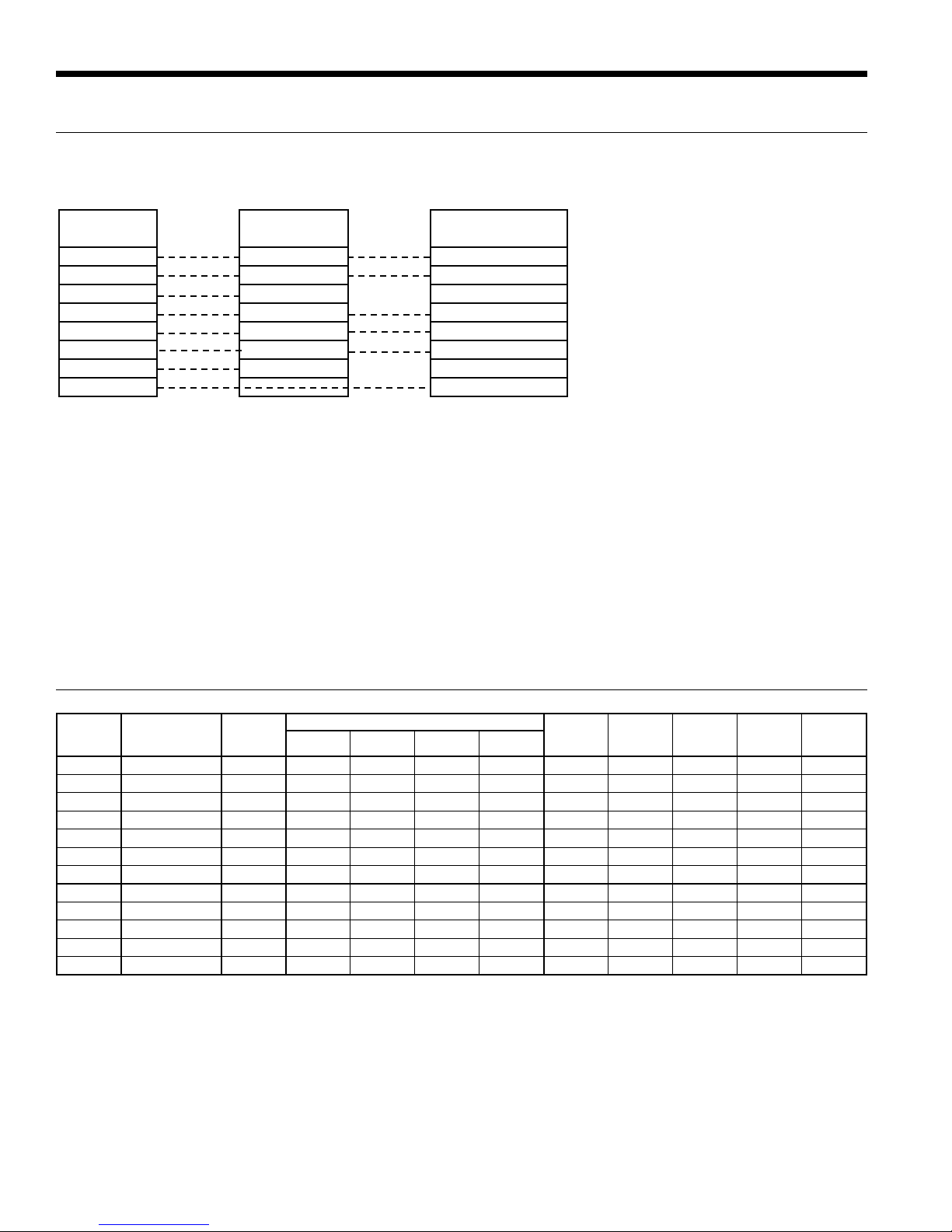
Single and Dual Capacity Wiring Diagram
Field low voltage point to point wiring:
From
Thermostat T o Air Handler
CC C
RR R
GG
OO O
Y1 Y1 Y1
Y2 Y2 Y2
W2 W
LL
Air Handler transformer must be 75VA.
To Compressor
Section
5/29/08
Electrical Data
Model
022 208-230/60/1 187/253 14.0 9.0 48.0 17.0 0.4 5.4 14.8 17.1 25
030 208-230/60/1 187/253 20.0 12.8 58.3 21.0 0.4 5.4 18.6 21.8 30
036 208-230/60/1 187/253 22.0 14.1 73.0 26.0 0.4 5.4 19.9 23.4 35
042 208-230/60/1 187/253 26.0 16.6 79.0 28.0 0.4 5.4 22.4 26.6 40
048 208-230/60/1 187/253 31.0 19.8 109.0 38.0 0.4 5.4 25.6 30.6 50
060 208-230/60/1 187/253 41.2 26.4 134.0 47.0 0.4 5.4 32.2 38.8 60
070 208-230/60/1 187/253 44.2 28.3 158.0 63.0 0.4 5.4 34.1 41.2 70
026 208-230/60/1 187/253 18.2 11.6 58.3 21.0 0.4 5.4 17.4 20.3 30
038 208-230/60/1 187/253 23.8 15.2 83.0 30.0 0.4 5.4 21.0 24.8 40
049 208-230/60/1 187/253 33.0 21.1 104.0 37.0 0.4 5.4 26.9 32.2 50
064 208-230/60/1 187/253 42.3 27.1 152.9 54.0 0.4 5.4 32.9 39.7 70
072 208-230/60/1 187/253 46.3 29.6 179.2 63.0 0.4 5.4 35.4 42.8 75
Rated voltage of 208-230/60/1
HACR circuit breaker in USA only
ll fuses Class RK-5
* With optional GeoStart
Rated
Voltage
Voltage
Min/Max
MCC RLA LRA LRA*
Compressor HWA
Pump
FLA
Ext
Loop
FLA
Total
Unit
FLA
Min
Circ
Amp
Max
Fuse/
HACR
4/3/13
16
Page 17
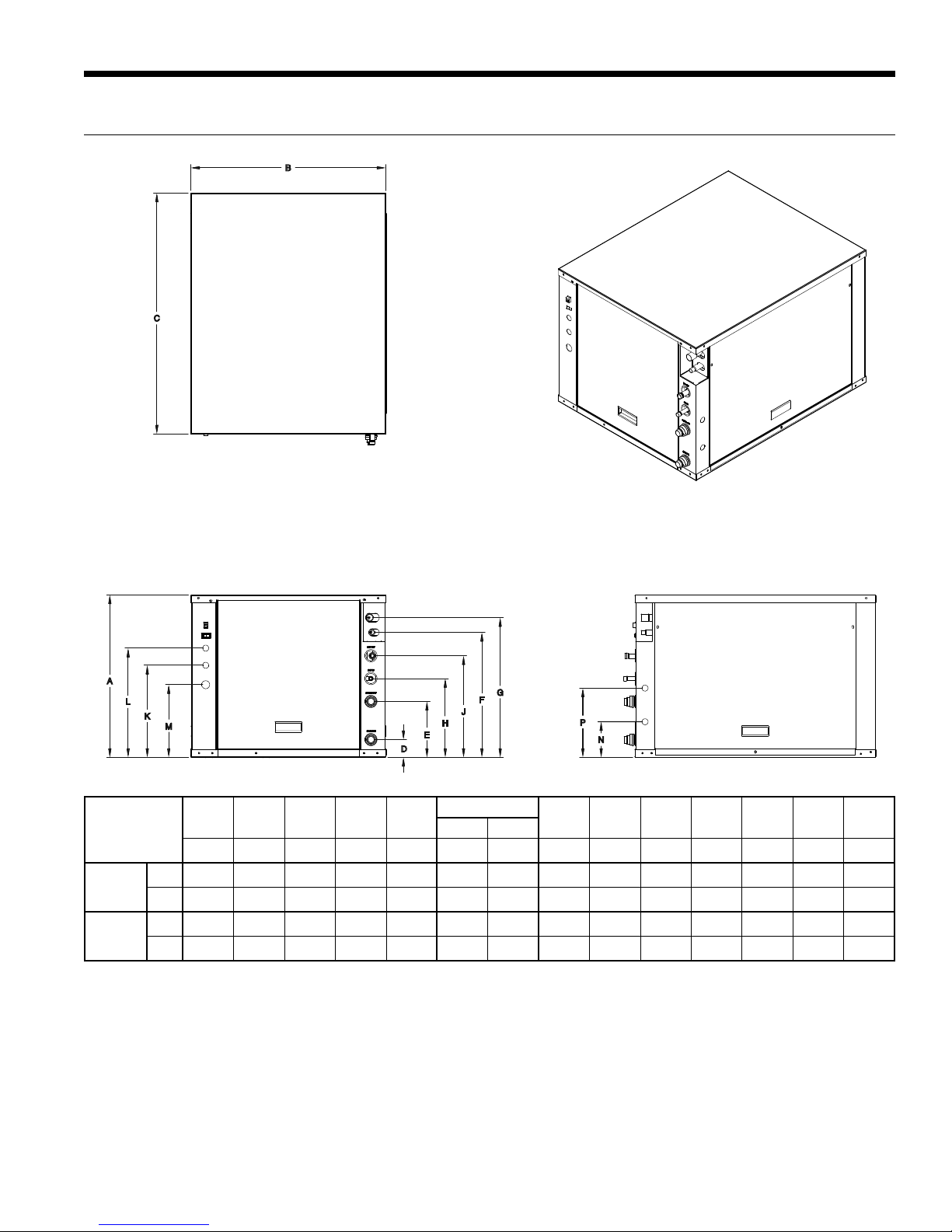
Dimensional Data
B
C
ASTON INDOOR SPLIT SERIES INSTALLATION MANUAL
A
L
Model
K
M
Height Width Depth
WaterInWater
D
Out
H
E
Liquid Gas
G
F
J
Service Valve
ABCDEFGHJKLMNP
022-030
036-072
in. 19.3 22.5 26.5 1.93 6.93 15.2 16.8 9.4 11.9 12.1 14.3 9.5 4.6 8.2
cm. 49.0 57.1 67.3 4.9 17.6 38.6 42.7 23.9 30.2 30.7 36.3 24.1 11.7 20.8
in. 21.25 25.62 31.6 2.3 7.21 16.4 18.3 10.3 13.3 12.1 14.3 9.5 4.7 9.1
cm. 54.0 65.1 80.3 5.8 18.5 41.7 46.5 26.2 33.8 30.7 36.3 24.1 11.9 23.1
Dimensions are in inches.
Decorative molding and water connections extend 1.2 in. [30.5 mm] beyond the front of the cabinet.
P
N
HWGInHWG
Out
Low
Voltage
External
Pump
Line
Voltage
Knock
Out
Knock
Out
17
Page 18
ASTON INDOOR SPLIT SERIES INSTALLATION MANUAL
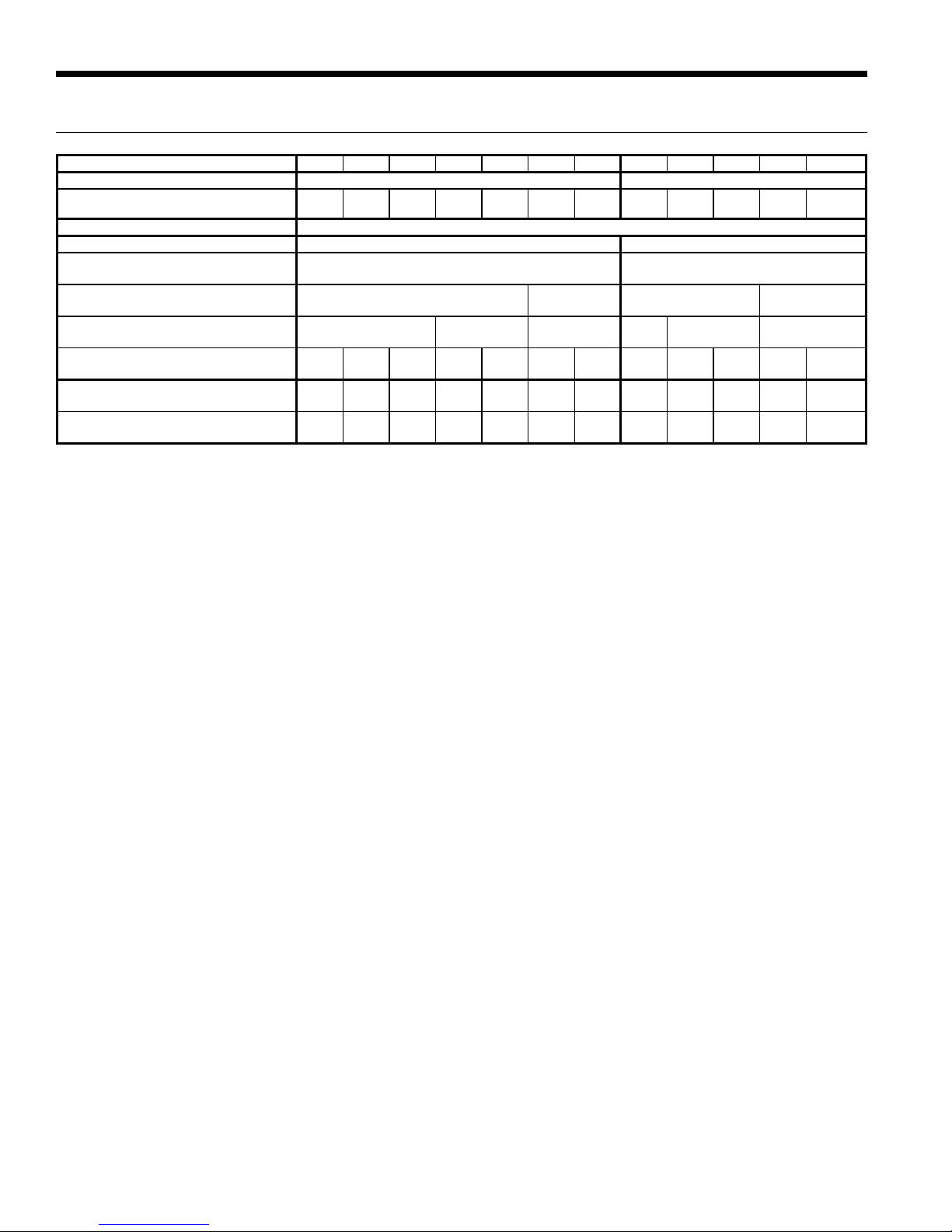
Physical Data
Model 022 030 036 042 048 060 070 026 038 049 064 72
Compressor (1 each) Single Speed Scroll Dual Capacity Scroll
Factory Charge R410a, oz [kg]
Coax and Water Piping
Water Connections Size - Swivel- in [mm] 1 [25.4] 1 [25.4]
HWG Connection Size - Female Sweat
(I.D.) - in [mm]
Brass Service Valve - Liquid Line - in [mm]
Brass Service Valve - Suction Line - in [mm]
Coax and Piping Water Volume - gal [l]
Weight - Operating, lb [kg]
Weight - Packaged, lb [kg]
NOTES: All units have TXV expansion devices, and 1/2 in. [12.2 mm] and 3/4 in. [19.1 mm] electrical knockouts.
Brass service valves are sweat type valves.
56
[1.59]
0.7
[2.6]
164
[74]
184
[83]
56
[1.59]
[9.525]
5/8
[15.875]
1.0
[3.8]
174
[79]
194
[88]
56
74
90
92
[22.225]
1.6
251
271
108
[3.06]
1/2
[12.7]
7/8
2.3
[8.7]
292
[132]
312
[142]
[1.59]
[4.9]
[105]
[2.1]
[2.55]
[2.61]
1/2 [12.7] 1/2 [12.7]
3/8
3/4
[19.05]
1.3
1.3
213
[97]
233
1.6
[6.1]
246
[112]
266
[121]
[6.1]
[114]
[123]
[4.9]
212
[96]
232
[106]
52
[1.47]
5/8
[15.875]
0.7
[2.6]
189
[186]
209
[95]
[1.59]
[9.525]
3/4 [19.05]
56
90
[2.55]
3/8
1.3
[4.9]
236
[107]
256
[116]
1.6
[6.1]
250
[113]
270
[122]
92
[2.61]
1.6
[6.1]
271
[123]
291
[132]
104 [2.95]
1/2
[12.7]
7/8
[22.225]
2.3
[8.7]
290
[132]
310
[141]
6/27/11
18
Page 19
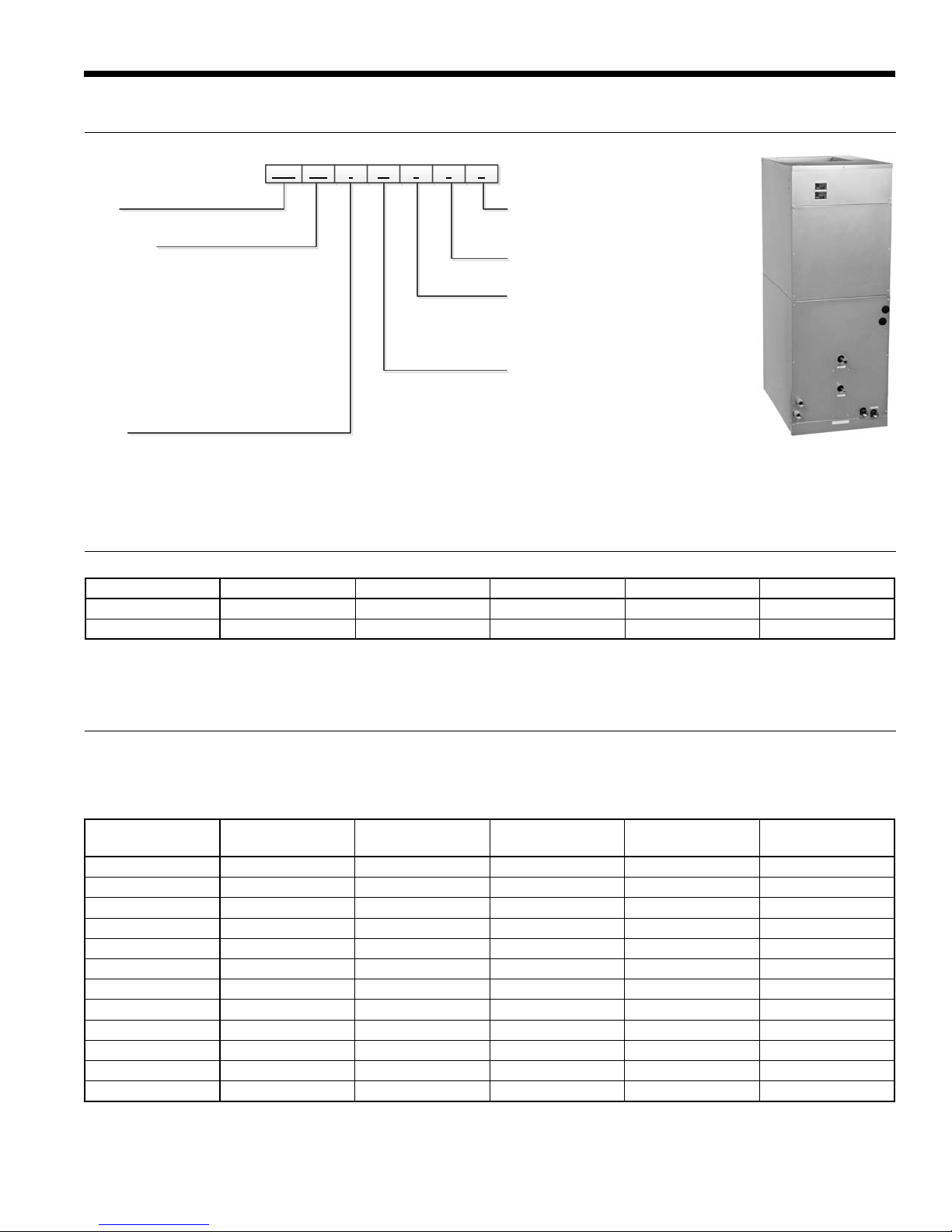
Model Nomenclature - Air Handler
A
A
1-3 4-6 7 8-9 10 11 12
GAH 036 * 00 0 1 R
ASTON INDOOR SPLIT SERIES INSTALLATION MANUAL
Model
GAH – G Series Air Handler
Unit Capacity
Refrigeration (DX) Models with Nominal CFM
022 MBTUH 800
026 MBTUH 925
030 MBTUH 980
036 MBTUH 1225
042 MBTUH 1425
048 MBTUH 1625
060 MBTUH 1760
Hydronic Models with Nominal CFM
026 MBTUH 925
036 MBTUH 1225
048 MBTUH 1625
060 MBTUH 1760
Vintage
* = Factory Use Only
NOTE: To field convert the GAH042-060 to bottomflow air discharge, the NAHBC kit must be ordered.
Air Coil
R – Refrigerant
H - Hydronic
Motor
1 – ECM 208-230/60/1
Disconnect
0 – No Breaker Installed
(only on 5kW & 10kW Heaters)
1 – Breaker Installed
(onlyon15kW&20kWHeaters)
Electric Heat
00 – None
05 – 5kW (022 – 036 only)
10 – 10kW (030 – 060 only)
15 – 15kW (042 – 060 only)
20 – 20kW (060 only)
Rev.: 08 April 2013D
Coil Data - Air Handler
Aston Split Model Matching Air Handler Coil Surface Area (ft2) FPI Rows Tube Diameter
022 - 038 GAH036 5.83 12 2 3/8 in.
042 - 072 GAH060 5.83 12 3 3/8 in.
Compatibility Table - Air Handler
ir Handler Sizing Selection
ir handlers should be designed for R-410A refrigerant and should be matched with the outdoor split compressor section according to the
table below.
Air Handler
GAH022A***1R 103*022 - 800 5
GAH026A***1R - 103*026 104*026 925 5
GAH030A***1R 103*030 - - 980 5, 10
GAH036A***1R 103*036 - - 1225 5, 10
GAH036A***1R - 103*038 104*038 1225 5, 10
GAH042A***1R 103*042 - - 1425 10, 15
GAH048A***1R 103*048 - - 1625 10, 15
GAH048A***1R - 103*049 104*049 1625 10, 15
GAH060A***1R 103*060 - - 1760 10, 15, 20
GAH060A***1R - 103*064 104*064 1760 10, 15, 20
GAH060A***1R 103*070 - - 1760 10, 15, 20
GAH060A***1R - 103*072 104*072 1760 10, 15, 20
Indoor Split Model
(Single)
Indoor Split Model
(Dual Capacity)
Outdoor Split Model
(Dual Capacity)
19
Airfl ow (CFM) Electric Heat (kW)
Page 20
ASTON INDOOR SPLIT SERIES INSTALLATION MANUAL
Physical Data - Air Handler
Air Handler Model Number (Refrigerant) GAH022 GAH026 GAH030 GAH036 GAH042 GAH048 GAH060
Air Coil Total Face Area - ft
Tube Outside Diameter - in [mm] 3/8 [9.52]
Evaporator Coil
Refrigerant R-410a
Nominal Cooling Capacity - Ton [kW] 1.8 [6.44] 2.1 [7.59] 2.5 [8.79] 3.0 [10.55] 3.5 [12.30] 4.0 [14.06] 5 [17.58]
Condensate Drain Connection - (FPT) in [mm] 3/4 [19.05]
Blower Wheel Size - (Dia x W) in [mm] 11 x 10 [279 x 254]
Blower Motor Type/Speeds Variable Speed ECM
Blower Motor Output - hp [W] 1/2 [373] 1 [746]
Filter Standard - 1" [51mm] MERV3 Disposable - in [mm] 20 x 24 [508 x 635]
Electrical Characteristics (60hz) 208/230/60/1
Shipping Weight - lbs [kg] 215 [97.52] 220 [99.79]
Operating Weight - lbs [kg] 195 [88.45] 200 [90.71]
Number of Rows 2 3
Fins Per Inch 12
Suction Line Connection - in [mm] Sweat 5/8 [15.87] 7/8 [22.22]
Liquid Line Connection - in [mm] Sweat 3/8 [9.52]
2
[m2] 5.83 [0.54]
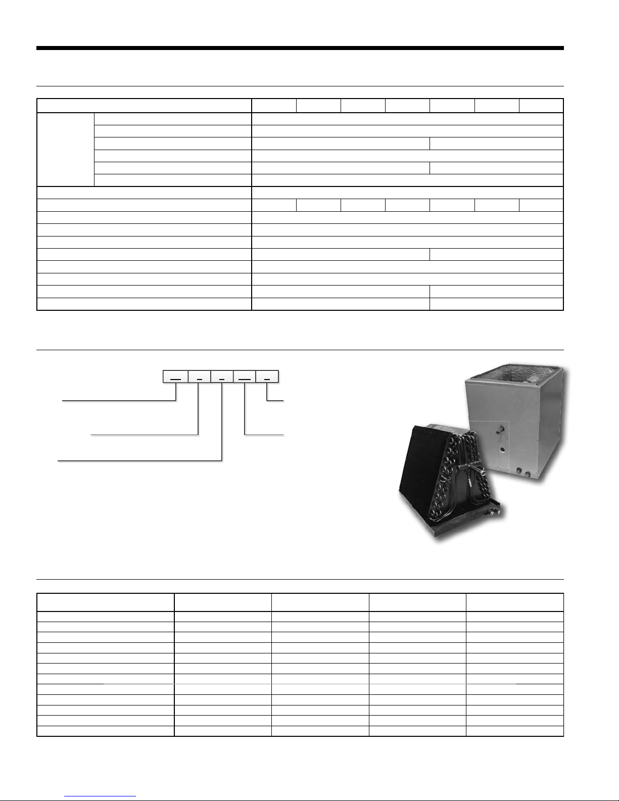
Model Nomenclature - Coil
1-2 3 4 5-7 8
GR A C 026 C
Model
GR – G Series Refrigerant Coil
GH – G Series Hydronic Coil
Configuration
A – “A” Coil
Type
C - Coil
NOTE: All refrigerant coils include TXV.
Refrigerant Coil Compatibility
Encased/Uncased Coil Indoor Split Model (Single)
GRAC026* 103*022 - 800
GRAC026* - 103*026 104*026 925
GRAC026* 103*030 - - 980
GRAC036* 103*036 - - 1225
GRAC036* - 103*038 104*038 1225
GRAC048* 103*042 - - 1425
GRAC048* 103*048 - - 1625
GRAC048* - 103*049 104*049 1625
GRAC060* 103*060 - - 1760
GRAC060* - 103*064 104*064 1760
GRAC060* 103*070 - - 1760
GRAC060* - 103*072 104*072 1760
Cabinet
C – Enclosed (Cased)
U – Uncased
Capacity
Refrigerant (DX) Models
026 MBTUH
036 MBTUH
048 MBTUH
060 MBTUH
Hydronic Models
060 MBTUH
Rev.: 08 April 2013D
Indoor Split Model
(Dual Capacity)
Outdoor Split Model
(Dual Capacity)
Recommended Airfl ow
(CFM)
7/14/08
20
Page 21
ASTON INDOOR SPLIT SERIES INSTALLATION MANUAL
A
The Aurora™ Control System
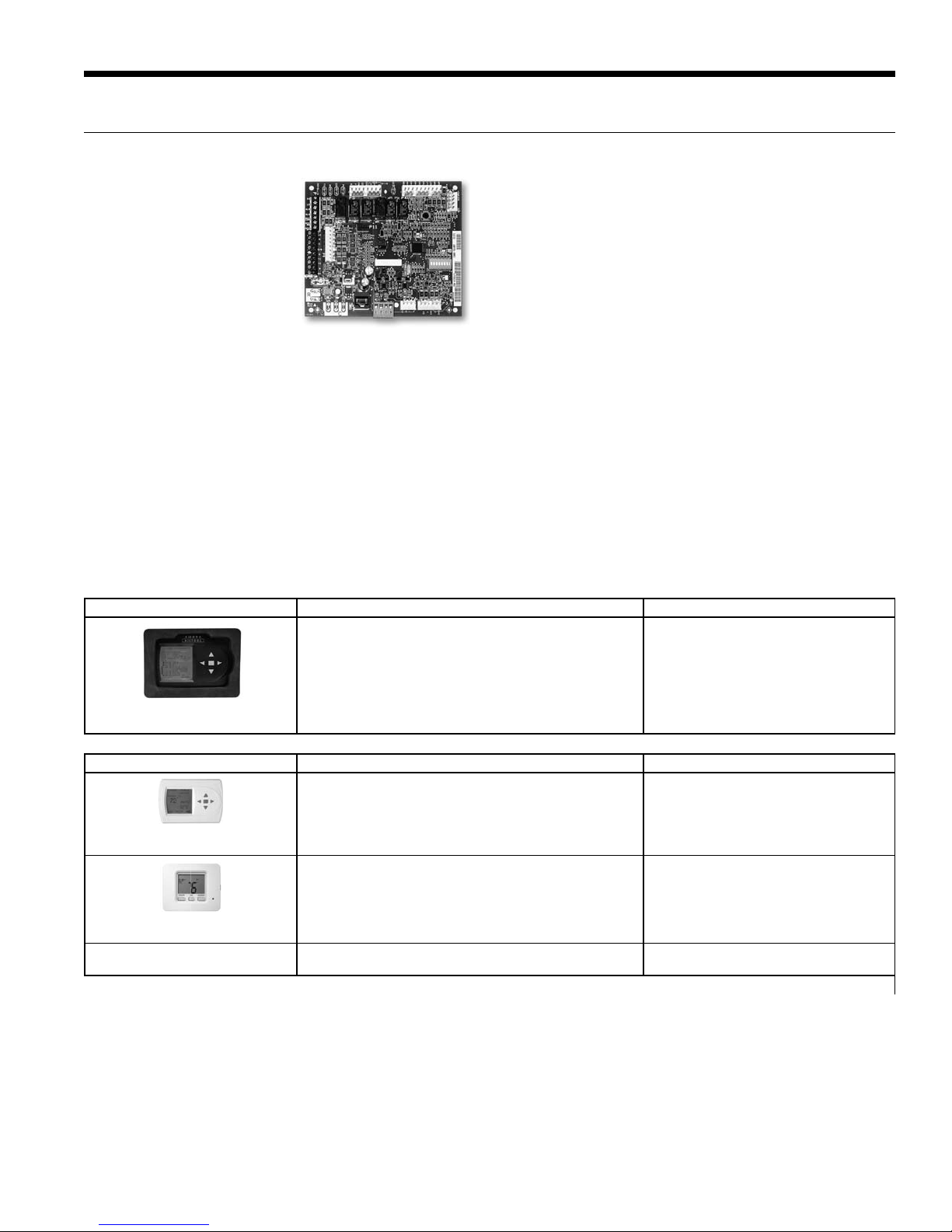
Aurora ‘Base’ Control
The Aurora ‘Base’ Control
(ABC) System is a complete
residential and commercial
comfort system that brings all
aspects of the HVAC system
into one cohesive module
network. The ABC features
microprocessor control and HP,
LP, and freeze detection, over/
under voltage faults, along with
communicating thermostat capability for complete fault detection
text at the thermostat.
urora uses the Modbus communication protocol to communicate
between modules. Each module contains the logic to control all
features that are connected to the module. The Aurora ‘Base’
Control (ABC) has two Modbus channels. The first channel is
configured as a master for connecting to devices such as a
communicating thermostat, expansion board, or other slave
devices. The second channel is configured as a slave for
connecting the Aurora Interface Diagnostics Tool (AID Tool).
Service Device Description Aurora ‘Base’
Allows setup, monitoring and troubleshooting of any
Aurora Control.
NOTE: Although the ABC has basic compatibility with all Aurora, new
product features may not be available on older AID Tools. To simplify
Aurora Interface and Diagnostics
Add On Thermostats and Zoning Description Aurora ‘Base’
TP32U03GSR/04GSR - MonoChrome
Traditional Y1, Y2 Thermostat
Traditional Y1, Y2 Thermostat
IntelliZone
(AID) Tool
TP32S01GSR/02GSR -
®
Zoning Compatibility
the basic compatibility ensure the version of AID is at least the same
or greater than the ABC software version.
Elite Stat with full English fault codes and alerts, traditional Y1, Y2
thermostat
Traditional Y1, Y2 thermostat Optional
IntelliZone® is a non-communicating zoning system requiring Y1, Y2
signals and controls the ECM blower motor directly.
For Service
(Ver. 1.xx or greater)
Optional
Optional
(ECM Preferred)
21
Page 22
ASTON INDOOR SPLIT SERIES INSTALLATION MANUAL
The Aurora Control System cont.
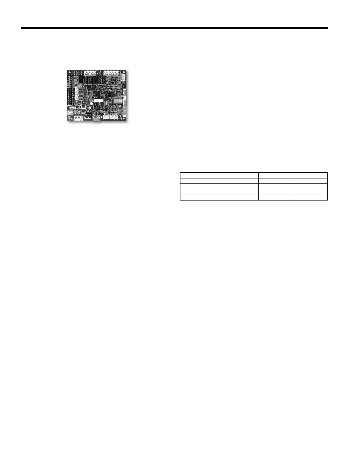
Aurora ‘Base’ Control
NOTE: Refer to the Aurora Base Control Application and
Troubleshooting Guide and the Instruction Guide: Aurora Interface and
Diagnostics (AID) Tool for additional information.
Control Features
Software ABC Standard Version 2.0
Single or Dual Capacity Compressors
Either single or dual capacity compressors can be operated.
Other Control Features
• Random start at power up
• Anti-short cycle protection
• High and low pressure cutouts
• Loss of charge
• Water coil freeze detection
• Over/under voltage protection
• Load shed
• Emergency shutdown
• Hot gas reheat operation (where applicable)
• Diagnostic LED
• Test mode push button switch
• Two auxiliary electric heat outputs
• Alarm output
• Accessory output with N.O. and N.C.
• Modbus communication (master)
• Modbus communication (slave)
Field Selectable Options via Hardware
DIP Switch (SW1) – Test/Configuration Button (See SW1
Operation Table)
Reset Configuration Mode
The control is placed in reset configuration mode by holding the
push button switch SW1 for 50 to 60 seconds. This will reset
all configuration settings and the EEPROM back to the factory
default settings. LED3 (green) will turn off when entering reset
configuration mode. Once LED3 (green) turns off, release SW1
and the control will reset.
DIP Switch (SW2)
SW2-1 FP1 Selection – Low water coil temperature limit setting
for freeze detection. On = 30°F; Off = 15°F.
SW2-2 FP2 Selection – On = 30°F; Off = N/A
SW2-3 RV – O/B - thermostat type. Heat pump thermostats
with “O” output in cooling or “B” output in Heating can be
selected. On = O; Off = B.
SW2-4 Access Relay Operation (P2)
and 2-5
Access Relay Operation SW2-4 SW2-5
Cycle with Blower ON ON
Cycle with Compressor OFF OFF
Water Valve Slow Opening ON OFF
Cycle with Comm. T-stat Hum Cmd OFF ON
Cycle with Blower - The accessory relay will cycle with the
blower output.
Cycle with Compressor - The accessory relay will cycle with the
compressor output.
Water Valve Slow Opening - The accessory relay will cycle and
delay both the blower and compressor output for 90 seconds.
SW2-6 CC Operation – selection of single or dual capacity
compressor. On = Single Stage; Off = Dual Capacity
SW2-7 Lockout and Alarm Outputs (P2) – selection of a
continuous or pulsed output for both the LO and ALM
Outputs. On = Continuous; Off = Pulsed
SW2-8 Future Use
Alarm Jumper Clip Selection
From the factory, ALM is connected to 24 VAC via JW2. By cutting
JW2, ALM becomes a dry contact connected to ALG.
Test Mode
The control is placed in the test mode by holding the push button
switch SW1 for 2 - 5 seconds. In test mode most of the control
timings will be shortened by a factor of sixteen (16). LED3 (green)
will flash at 1 second on and 1 second off. Additionally, when
entering test mode LED1 (red) will flash the last lockout one
time. Test mode will automatically time out after 30 minutes. Test
mode can be exited by pressing and holding the SW1 button for
2 to 5 seconds or by cycling the power. NOTE: Test mode will
automatically be exited after 30 minutes.
22
Page 23

The Aurora ‘Base’ Control System cont.
A
ASTON INDOOR SPLIT SERIES INSTALLATION MANUAL
Safety Features
The following safety features are provided to protect the
compressor, heat exchangers, wiring and other components from
damage caused by operation outside of design conditions.
Fuse – a 3 amp automotive type plug-in fuse provides protection
against short circuit or overload conditions.
nti-Short Cycle Protection – 4 minute anti-short cycle protection
for the compressor.
Random Start – 5 to 80 second random start upon power up.
Fault Retry – in the fault condition, the control will stage off the
outputs and then “try again” to satisfy the thermostat Y input
call. Once the thermostat input calls are satisfied, the control will
continue on as if no fault occurred. If 3 consecutive faults occur
without satisfying the thermostat Y input call, then the control will
go to Lockout mode.
Lockout – when locked out, the blower will operate continuously,
and PSC blower motor output will remain on. The Alarm output
(ALM) and Lockout output (L) will be turned on. The fault type
identification display LED1 (Red) shall flash the fault code. To reset
lockout conditions with SW2-8 On, thermostat inputs “Y1”, “Y2”,
and “W” must be removed for at least 3 seconds. To reset lockout
conditions with SW2-8 Off, thermostat inputs “Y1”, “Y2”, “W”, and
“DH” must be removed for at least 3 seconds. Lockout may also be
reset by turning power off for at least 30 seconds or by enabling the
emergency shutdown input for at least 3 seconds.
High Pressure – fault is recognized when the Normally Closed
High Pressure Switch, P4-9/10 opens, no matter how momentarily.
The High Pressure Switch is electrically in series with the
Compressor Contactor and serves as a hard-wired limit switch if
an overpressure condition should occur.
Low Pressure - fault is recognized when the Normally Closed
Low Pressure Switch, P4-7/8 is continuously open for 30 seconds.
Closure of the LPS any time during the 30 second recognition
time restarts the 30 second continuous open requirement. A
continuously open LPS shall not be recognized during the 2 minute
startup bypass time.
Loss of Charge – fault is recognized when the Normally Closed Low
Pressure Switch, P4-7/8 is open prior to the compressor starting.
Freeze Detection (Coax) - set points shall be either 30°F or 15°F.
When the thermistor temperature drops below the selected set
point, the control shall begin counting down the 30 seconds delay.
If the thermistor value rises above the selected set point, then the
count should reset. The resistance value must remain below the
selected set point for the entire length of the appropriate delay to
be recognized as a fault. This fault will be ignored for the initial 2
minutes of the compressor run time.
Over/Under Voltage Shutdown - An over/under voltage condition
exists when the control voltage is outside the range of 18 VAC to
30 VAC. If the over/under voltage shutdown lasts for 15 minutes,
the lockout and alarm relay will be energized. Over/under voltage
shutdown is self-resetting in that if the voltage comes back within
range of 18 VAC to 30 VAC for at least 0.5 seconds, then normal
operation is restored.
Operation Description
Power Up - The unit will not operate until all the inputs and safety
controls are checked for normal conditions. The unit has a 5 to 80
second random start delay at power up. Then the compressor has
a 4 minute anti-short cycle delay after the random start delay.
Standby In standby mode, Y1, Y2, W, DH, and G are not active.
Input O may be active. The blower and compressor will be off.
Heating Operation
Heating, 1st Stage (Y1) - The blower is started immediately and the
compressor is energized 10 seconds after the Y1 input is received.
Heating, 2nd Stage (Y1, Y2) - The compressor will be staged to
full capacity 20 seconds after Y2 input is received. The ECM blower
will shift to high speed.
Heating, 3rd Stage (Y1, Y2, W) - The hot water pump is deenergized and the first stage of electric heat is energized 10
seconds after the W command is received. If the demand
continues the second stage of electric heat will be energized after
5 minutes.
Emergency Heat (W Only) - When the unit is matched with an air
handler listed in the Air Handler Compatibility table, the thermostat
will send the "W" input to the air handler's control board. The blower
is started on high speed, and the first stage of resistance heat is
energized 10 seconds after the "W" input. Continuing demand will
engage the additional stages of resistance heat 90 seconds after
the first stage.
Cooling Operation
In all cooling operations, the reversing valve directly tracks the O
input. Thus, anytime the O input is present, the reversing valve will
be energized.
Cooling, 1st Stage (Y1, O) - The blower is started immediately and
the compressor is energized 10 seconds after the Y1 input is received.
Cooling, 2nd Stage (Y1, Y2, O) - The compressor will be staged to
full capacity 20 seconds after Y2 input is received. The ECM blower
will shift to high speed.
Blower (G) - The blower will start immediately upon receiving a
thermostat G command. If there are no other commands from the
thermostat the ECM will run on “G” speed until the G command is
removed. Regardless of blower input (G) from the thermostat, the
blower will remain on for 30 seconds at the end of each heating,
cooling, and emergency heat cycle.
23
Page 24
ASTON INDOOR SPLIT SERIES INSTALLATION MANUAL
1
2
The Aurora ‘Base’ Control System cont.
Emergency Shutdown - Four (4) seconds after a valid ES input,
P2-7 is present, all control outputs will be turned off and remain
off until the emergency shutdown input is no longer present. The
first time that the compressor is started after the control exits
the emergency shutdown mode, there will be an anti-short cycle
delay followed by a random start delay. Input must be tied to
common to activate.
Load Shed -
The LS input disables all outputs with the exception
of the blower output. When the LS input has been cleared, the antishort cycle timer and random start timer will be initiated. Input must
be tied to common to activate.
Aurora ‘Base’ Control LED Displays
These three LEDs display the status, configuration, and fault
codes for the control. These can also be read in plain English via
the Aurora AID Tool.
Status LED (LED3, Green)
Description of Operation Fault LED, Green
Normal Mode ON
Control is Non-functional OFF
Test Mode Slow Flash
Lockout Active Fast Flash
Dehumidification Mode Flash Code 2
(Future Use) Flash Code 3
(Future Use) Flash Code 4
Load Shed Flash Code 5
ESD Flash Code 6
(Future Use) Flash Code 7
Configuration LED (LED2, Yellow)
Description of Operation Configuration LED, Yellow
No Software Overwritten Flashing ECM Setting
DIP Switch was Overwritten Slow Flash
ECM Configuration Mode Fast Flash
Fault LED (LED1, Red)
Red Fault LED
Normal - No Faults OFF –
Fault - Input 1 No Auto
Fault - High Pressure 2 Yes Hard or Soft
Fault - Low Pressure 3 Yes Hard or Soft
Fault - Freeze Detection FP2 4 Yes Hard or Soft
Fault - Freeze Detection FP1 5 Yes Hard or Soft
Fault - Condensate Overflow 7 Yes Hard or Soft
ABC Basic Faults
Fault - Over/Under Voltage 8 No Auto
Fault - FP1 & FP2 Sensor Error 11 Yes Hard or Soft
NOTE: All codes >11 use long flash for tens digit and short flash for the ones digit. 20,
30, 40, 50, etc. are skipped.
LED Flash
Code*
Lockout Reset/Remove
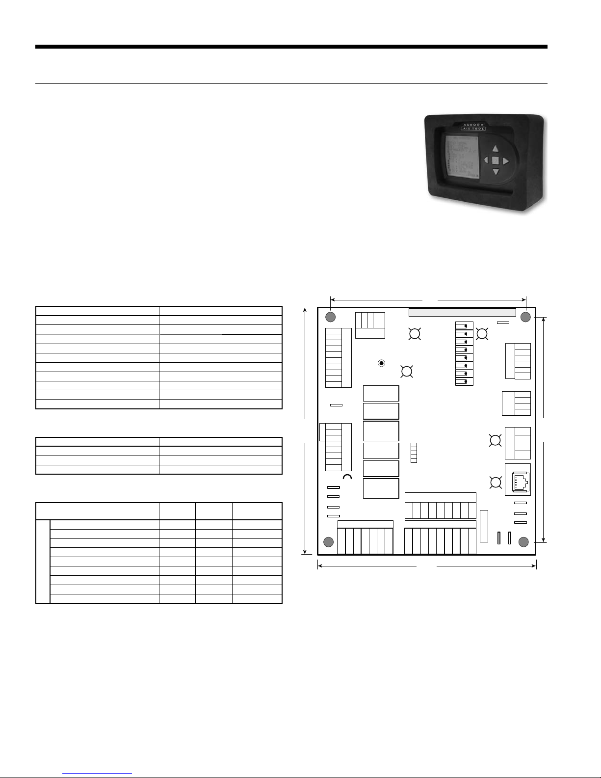
Aurora Interface and Diagnostics (AID) T ool
The Aurora Interface and
Diagnostics (AID) Tool is a
device that is a member of
the Aurora network. The AID
Tool is used to troubleshoot
equipment which uses the
Aurora control via Modbus
RTU communication. The AID
Tool provides diagnostics,
fault management,
ECM setup, and system
configuration capabilities to the Aurora family of controls. An AID
Tool is recommended, although not required, for ECM airflow
settings. The AID Tool simply plugs into the exterior of the cabinet
in the AID Tool port.
ABC Control Board Layout
5.0 in.
On
o
F/30oF
FP1 – 15
o
F/30oF
FP2 – 15
RV – B/O
ACC – Dip
ACC – Dip
Reheat/Normal
Control
C
G
O/B
Field ConnectionsField Connections
C
G
O/B
Off
LED 2
1
2
YR
3
Config
4
5
6
7
8
SW2
Com1
Com2
W
Y1
Y2
DH
W
Y1
Y2
DH
LED 5
LED 4
3A-Fuse
P6
G
G
RR
EH1
P3
Factory
RS485
P7
RS 485
P8
RS485 NET
EH2
C
EH1
C
CO
N/A
(+)
(-)
R
Exp
C
(+)
(-)
R
C
CC
C
6.25 in.
C
CFM
PWM
HP
HP
LP
LP
FP2
FP2
FP1
FP1
REV
REV
CC2
G
LO
CC2
HI
CCG
CC
FG
F
R
F
CC
G
Y1
P4
Factory
P5
Factory
JW2 - Alarm
P2
LS
ES
P13
ALM
ECM PWM
SW1 Test
RV – K1
CC – K2
CC Hi – K3
Fan – K4
Alarm – K5
Acc – K6
ALG
ACC c
ACC no
ACC nc
LED 1
Fault
LED 3
CC – Dual/Single
G
L – Pulse/Continuous
Status
AuroraTM Base
Factory Use
P11
P9
Factory Fan Connection
R
LO
P1
R
LO
5.5 in.
5.75 in.
24
Page 25
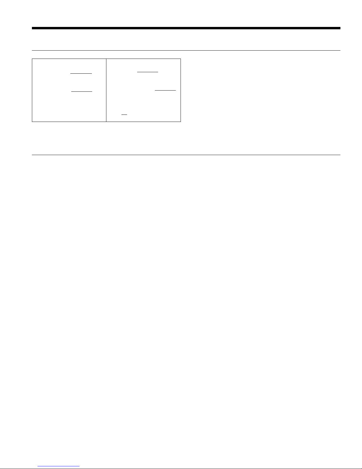
Reference Calculations
Heating Calculations: Cooling Calculations:
LWT = EWT -
HE
gpm x 500
LWT = EWT +
gpm x 500
ASTON INDOOR SPLIT SERIES INSTALLATION MANUAL
HR
LAT = EAT +
TH = HC + HW
HC
cfm x 1.08
LAT (DB) = EAT (DB) -
LC = TC - SC
SC
S/T =
TC
cfm x 1.08
Legend
Abbreviations and Definitions
cfm = airflow, cubic feet/minute
EWT = entering water temperature, Fahrenheit
gpm = water flow in gallons/minute
WPD = water pressure drop, psi and feet of water
EAT = entering air temperature, Fahrenheit (dry bulb/wet bulb)
HC = air heating capacity, MBtu/h
TC = total cooling capacity, MBtu/h
SC = sensible cooling capacity, MBtu/h
kW = total power unit input, kilowatts
HR = total heat of rejection, MBtu/h
HE = total heat of extraction, MBtu/h
SC
HWC = hot water generator capacity, MBtu/h
EER = Energy Efficient Ratio
= Btu output/Watt input
COP = Coefficient of Performance
= Btu output/Btu input
LWT = leaving water temperature, °F
LAT = leaving air temperature, °F
TH = total heating capacity, MBtu/h
LC = latent cooling capacity, MBtu/h
S/T = sensible to total cooling ratio
25
Page 26
ASTON INDOOR SPLIT SERIES INSTALLATION MANUAL
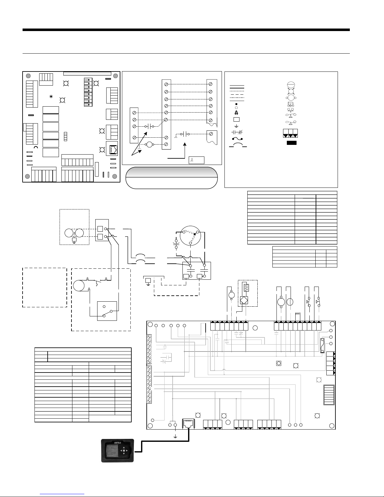
Wiring Schematics
Split Wiring Schematic - 208-230/60/1
C
CFM
PWM
HP
ECM PWM
P4
HP
P13
LP
LP
FP2
FP2
FP1
Factory
SW1 Test
FP1
REV
REV
CC2
LO
CC2
HI
CCG
CC
FG
F
CC
G
Y1
G
F
R
JW2 - Alarm
RV – K1
CC – K2
P5
CC Hi – K3
Fan – K4
Factory
Alarm – K5
Acc – K6
P2
LS
ES
ALG
ALM
ACC c
ACC nc
ACC no
Water Solenoid
(see Open Loop
Groundwater Systems
section)
1 second on and 1 second off
Slow Flash
100 milliseconds on and 100 milliseconds off
Fast Flash
100 millisec o n ds on and 400 m illise c onds off with a 2 second pause before repeating
Flash Code
Random Start Delay (Alternating Colors)
Status LED (LED1, Green)
Configuration LED (LED2, Yellow)
Fault LED (LED3, Red)
Fault LED (LED1, Red)
Normal Mode
Input Fault Lockout
High Pressure Lockout
Low Pressure Lockout
Futu re U s e
Freeze Detection – FP1
Reserved
Condensate Overflow Lockout
Over/Under Voltage Shutdown
Futu re U s e
Futu re U s e
FP1 and FP2 Sensor Error
LED1
FP1 – 15oF/30oF
o
F/30oF
FP2 – 15
RV – B/O
Fault
ACC – Dip 4
ACC – Dip 5
LED3
CC – Dual/Single
G
L – Pulse/Continuous
Status
Reheat/Normal
AURORA BASE
CONTROL™
Factory Use
P11
P9
Factory Fan Connection
C
R
G
LO
O/B
Field ConnectionsField Connections
P1
C
R
G
LO
O/B
Ext Pump
1/2 hp Total
208-230/60/1
Pump
Pump
G
DHW
Pump
Aurora LED Flash Codes
Fast Flash
Fast Flash
Fast Flash
OFF
Flash Code 1
Flash Code 2
Flash Code 3
Flash Code 4
Flash Code 5
Flash Code 6
Flash Code 7
Flash Code 8
Flash Code 9
Flash Code 10
Flash Code 11
On
Off
LED2
1
EH1
2
YR
3
Config
P3
4
5
6
7
8
SW2
Y2
Y1
Y1
Y2
Blue
W
DH
W
DH
Hot Water
Limit Switch
Com1
Com2
130°F
3A-Fuse
1
1
2
LED5
G
LED4
G
PB1
HW Switch
P6
P7
P8
RR
1
2
Purple
Cabinet
3
1
Optional Internal
Hot Water Generation Pump
Configuration LED (LED2, Yel low)
No Software Overide
DIP Switch Overide Slow Flash
Status LED (LED3, Green)
Normal Mode
Control is Non-Functional
Test Mode
Lockout Active
Dehumidification Mode
Futu re U s e
Futu re U s e
Load Shed
ESD
Futu re U s e
EH2
EH1
Factory
RS485 Exp
RS 485
RS485 NET
2
C
C
CO
N/A
(+)
(-)
R
C
(+)
(-)
R
C
Violet(7)
Blue
Flash Code 2
Flash Code 3
Flash Code 4
Flash Code 5
Flash Code 6
Flash Code 7
CC
C
Violet(8)
OFF
ON
OFF
Slow Flash
Fast Flash
Duel Fuel Wiri ng Diagram
Using Field Instal led Relay
Fossil Fuel
Furnace
C
R
W
Auxiliary Heat Relay
G
Auxiliary Heat Relay
Note 1: Field inst alled SPST dual fuel rel ay
(Required for dual fuel install ation)
Thermostat
Y1
Y2
O
L
Common C ommon
24 VAC
Fan
C
R
G
W
Notes
1 – Field inst alled SPST relay required f or duel fuel applications
Cap
Circuit Breaker
5A
Black(2)
5A
Circuit Breaker
Black(3)
Unit Power Supply
208-230/60/1
G
EH1
P2
ES
LS
ALM
ALG
ACC COM
ACC NO
ACC NC
LO
R
C
O/B
G
Y1
Y2
W
DH
P1
R
CC2
K5-Alarm
Relay
C
Green(11)
1st Stage Compressor
2nd Stage Compressor
Reversing Valve
Fault Signal
24 VAC
Auxilia r y
Heat Relay
S
Blue
Tan(6)
CCFC
K6-Acc
Relay
RS485 NET
= chassis
R
Red
T2 T1
CC
P9
Com2
LED5
P8
Compressor
C
Black
L1L2
G
Split
Y1
Y2
O
P1
LO
C
R
P2
ES
Violet(14)
JW2
RFFGCCCCG
K4-Fan Relay
Com1
LED5
RS485 NET
R-+
Factory Low voltage wiring
Factory Line voltage wiring
Field low voltage wiring
Field line voltage wiring
Optional block
DC Voltage PCB traces
Junction
Quick connect terminal
Wire nut
Field wire lug
L1
Ground
Relay Contacts-
N.O., N.C.
Fuse
Breaker
Com p re s so r C o n ta cto r
CC -
Condensate overflow sensor
CO -
DHW pum p relay
K5 -
Loop pump relay
K6 -
PSC Fan Speed Relay
CR3 -
PSC Fan Power Rel ay
CR4 CS - Compressor Solenoid
Fuses
F1 and F2 -
Heater element
HE -
High pressure switch
HP FP1 -
Freeze protection sensor
Low pressure switch
LP -
Event
Random Start Delay
Compressor On Delay
Compress or Minimum On Ti me
Compressor Short Cycle Delay
Blower Off Delay
Fault Recognition Delay – High Pressure
Start-Up Bypass – Low Pressure
Fault Recognition Delay – Low Pressure
Start-Up Bypass – Low Water Coil Limit
Fault Recognition Delay – Low Water Coil Limit
Fault Recognition Delay – Condensate Overflow
Thermostat Call Recognition Time
Water Valve Slow Open Delay
Dual Capacity
Units Only
UltraTech
CS
CC
RCP
Black(15)
Blue(16)
Blue(18)
CC2HICC2LOCC2
P5
G
K2-CC Relay
K3
-CC2 R e lay
Aurora Base Control
(ABC)
G
RS485 EXP
C
R-+C
P7
Legend
Thermistor
T
Light emitting diode - Green
G
Relay coil
Capacitor w/ bleed resistor
Switch - Condensate overflow
Switch - High pressure
Switch - Low pressure
132
P
Aurora Timing Events
Cycle with Blower ON ON
Cycle with Compressor OFF OFF
Water Valve Slow Opening ON OFF
Cycle with Comm. T-stat Hum Cmd OFF ON
RV
Orange
RV
Orange
REVREV FP1 FP1 FP2 FP2 LPS LPS HPS HPS
K1-RV Relay
SW1
Test Mode
CO
P6
EH2CEH1
C
P3
Polarized connector
Current Transducer (CT)
Power blocks
PB1, PB2 -
Pow e r strip
PS -
Reversing Valve coil
RV -
DIP package 5 position AXB
SW1 -
TEST MODE ABC Board
SW1 -
DIP package 8 position ABC Board
SW2 -
The r mal lim it s witch
TS HWL -
Hot water lim it s e n so r
SC -
Start Contactor
Start Relay
SR -
Water Coil Limit Sensor
WCL -
Normal Mode
5 to 80 seconds 1 second
5 seconds < 1 second
2 minutes 5 seconds
4 minutes 15 seconds
30 seconds 2 seconds
Less than 1 second
ABC SW2 Accessory Relay
DESCRIPTION SW2-4 SW 2-5
FP1
Yellow
Less than 1 second
2 minutes
30 seconds 30 seconds
2 minutes
30 seconds
30 seconds
2 seconds 2 seconds
90 seconds90 seconds
HP
LP
Black
Blue
T
Yellow
Status
LED3
G
Black
Blue
Fault
LED1
R
FP1 – 15°F/30° F
FP2 – 15°F/30° F
RV – B/O
Acc – Dip 4
Acc – Dip 5
CC – Dual/Single
L Output Type
Futu re U s e
Config
LED2
Y
CCGY1
Test Mode
30 seconds
30 seconds
30 seconds
30 seconds
P4
F1-3A
Off
SW2
4/3/1397P840-21
PWM
CFM
C
R
F
C
P13
On
1
2
3
4
5
6
7
8
AID Tool
26
Page 27
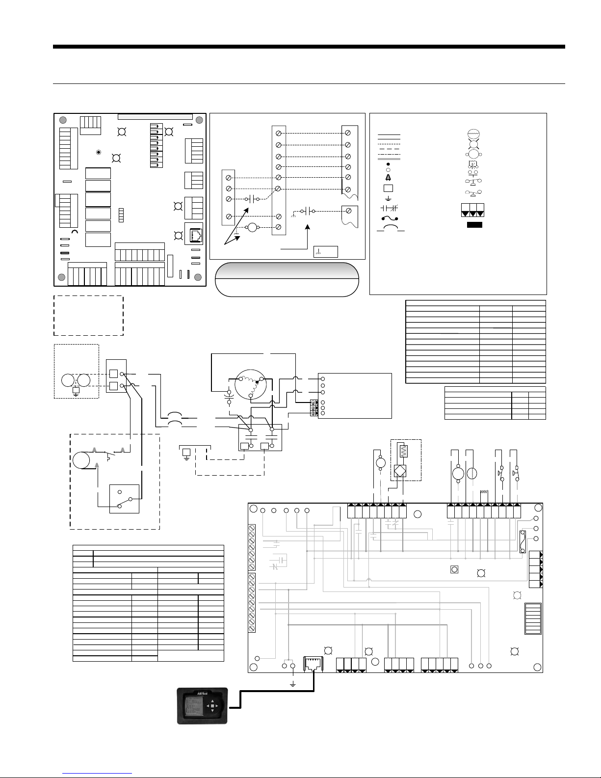
Wiring Schematics cont.
Split Wiring Schematic with GeoStart - 208-230/60/1
ASTON INDOOR SPLIT SERIES INSTALLATION MANUAL
C
CFM
PWM
HP
ECM PWM
P4
HP
P13
LP
LP
FP2
FP2
FP1
Factory
SW1 Test
FP1
REV
REV
CC2
LO
CC2
HI
CCG
CC
FG
F
CC
G
Y1
G
F
R
JW2 - Alarm
P2
RV – K1
CC – K2
P5
CC Hi – K3
Fan – K4
Factory
Alarm – K5
Acc – K6
LS
ES
ALG
ALM
ACC c
ACC nc
ACC no
Water Solenoid
(see Open Loop
Groundwater Systems
section)
Ext Pump
1/2 hp Total
208-230/60/1
Pump
Pump
G
Hot Water
Limit Switch
130°F
DHW
Pump
Blue
Optional Internal
Hot Water Generation Pump
1 second on and 1 second off
Slow Flash
100 millisec o n ds on and 100 m illise c o n d s o f f
Fast Flash
100 millisec o n ds on a n d 4 00 m illis e c o n ds off with a 2 s e c ond pause before repeating
Flash Code
Random Start Delay (Alternating Colors)
Status LED (LED1, Green)
Configuration LED (LED2, Yellow)
Fault LED (LED3, Red)
Fault LED (LED1, Red)
Normal Mode
Input Fault Lockout
High Pressure Lockout
Low Pressure Lockout
Futu re U s e
Freeze Detection – FP1
Reserved
Condensate Overflow Lockout
Over/Under Voltage Shutdown
Futu re U s e
Futu re U s e
FP1 and FP2 Sensor Error
LED1
FP1 – 15oF/30oF
FP2 – 15
RV – B/O
Fault
ACC – Dip 4
ACC – Dip 5
LED3
CC – Dual/Single
G
L – Pulse/Continuous
Status
Reheat/Normal
AURORA BASE
CONTROL™
Factory Use
P11
P9
Factory Fan Connection
C
R
LO
O/B
Field ConnectionsField Connecti ons
P1
C
R
LO
O/B
PB1
1
1
Violet(7)
1
2
2
Violet(8)
Purple
Blue
Cabinet
HW Switch
3
2
1
Aurora LE D Flash C o d es
Fast Flash
Fast Flash
Fast Flash
Flash Code 1
Flash Code 2
Flash Code 3
Flash Code 4
Flash Code 5
Flash Code 6
Flash Code 7
Flash Code 8
Flash Code 9
Flash Code 10
Flash Code 11
On
Off
LED2
1
o
2
YR
F/30oF
3
Config
4
5
6
7
8
SW2
LED5
Com1
LED4
Com2
G
W
Y2
Y1
DH
G
OFF
3A-Fuse
W
Y1
Y2
DH
Circuit Breaker
5A
5A
Circuit Breaker
Con f ig u ra t io n L ED (LED2, Y e llow)
No Software Overide
DIP Switch Overide Slow Flash
Status LED (LED3, Green)
Normal Mode
Control is Non-Functional
Test Mode
Lockout Active
Dehumidification Mode
Futu re U s e
Futu re U s e
Load Shed
ESD
Futu re U s e
EH1
EH2
P3
C
EH1
C
Factory
CO
N/A
(+)
P6
(-)
R
C
RS485 Exp
(+)
P7
(-)
G
R
RS 485
C
P8
G
RS485 NET
RR
Unit Power Supply
208-230/60/1
G
Duel Fuel Wiring Diagram
Usin g Field In s ta lle d Relay
Fossil Fuel
Furnace
C
Common C ommon
R
24 VAC
W
Auxiliary Heat Relay
G
Fan
Auxiliary Heat Relay
Note 1: Fi eld i nstall ed SPST dual fuel r elay
(Required for dual fuel install ation)
CC
C
1 – Fiel d install ed SPST relay requir ed for duel fuel appli cati ons
Compressor
S
Blue
Cap
Tan(6)
Black( 2)
Black( 3)
T2 T1
OFF
ON
OFF
Slow Flash
Fast Flash
Flash Code 2
Flash Code 3
Flash Code 4
Flash Code 5
Flash Code 6
Flash Code 7
P2
P1
R
ES
LS
ALM
ALG
ACC COM
ACC NO
ACC NC
LO
R
C
O/B
G
Y1
Y2
W
DH
R
= chassis
Run Winding
Active
Start
Common
P9
Com2
LED5
G
P8
Split
Y1
Y2
O
P1
LO
C
R
ES
JW2
R F FG CC CCG
RS485 NET
R-+
L1
P2
CC CO K5 K6 CR3 CR4 CS - Compressor Solenoid
F1 and F2 HE HP FP1 -
LP -
GeoStart
Dual Capacity
Units Only
CC
RCP
Black(15)
Violet(14)
Blue(16)
CC2HICC2LOCC2
K4-Fan Rel ay
K2-CC Relay
K3
-CC2 Rel ay
Aurora Base Control
(ABC)
Com1
LED5
G
RS485 EXP
C
R-+C
P7
Legend
Factory Low voltage wiring
Factory Line voltage wiring
Field low voltage wiring
Field line voltage wiring
Optional block
DC Voltage PCB traces
Junction
Quick connect terminal
Wir e n ut
Field wire lug
Ground
Relay ContactsN.O., N.C.
Fuse
Breaker
Compressor Contactor
Condensate overflow sensor
DHW pum p relay
Loop pump relay
PSC Fan Speed Relay
PSC Fan Power Relay
Fuses
Heater element
High pressure switch
Freeze protection sensor
Low pressure switch
Event
Random Start Delay
Compressor On Delay
Compressor Minimum On Ti me
Compressor Short Cycle Delay
Blower Off Delay
Fault Recognition Delay – High Pressure
Start-Up Bypass – Low Pressure
Fault Recognition Delay – Low Pressure
Start-Up Bypass – Low Water Coil Limit
Fault Recognition Delay – Low Water Coil Limit
Fault Recognition Delay – Condensate Overflow
The r mosta t Call R e c o g n it io n T ime
Water Valve Slow Open Delay
UltraTech
CS
Blue(18)
P5
G
CO
P6
P
Cycle with Blowe r ON ON
Cycle with Compressor OFF OFF
Water Valve Slow Opening ON OFF
Cycle with Comm. T-stat Hum Cmd OFF ON
RV
Orange
RV
Orange
REVREV FP1 FP1 FP2 FP2 LPS LPS HPS HPS
K1-RV Relay
SW1
Test Mode
EH2CEH1
C
Thermistor
T
Light emitting diode - Green
G
Relay coil
Capacitor w/ bleed resistor
Switch - Condensate overflow
Switch - High pressure
Switch - Low pressure
132
Polarized connector
Current Transducer (CT)
Power blocks
PB1, PB2 -
Power strip
PS -
Rev ersing Valve c o il
RV -
DIP package 5 position AXB
SW1 SW1 -
TEST MODE ABC Board
DIP package 8 position ABC Board
SW2 -
The rmal limit swit c h
TS HWL -
Hot water limit sensor
SC -
Start Contactor
Start Relay
SR -
Water Coil Limit Sensor
WCL -
Aurora T im ing E v en ts
Normal Mode
5 to 80 seconds 1 second
5 seconds < 1 second
2 minutes 5 seconds
4 minutes 15 seconds
30 seconds 2 seconds
Less than 1 second
ABC SW2 Accessory Relay
DESCRIPTION SW2-4 SW 2-5
FP1
Yellow
Less than 1 second
2 minutes
30 seconds 30 seconds
2 minutes
30 seconds
30 seconds
2 seconds 2 seconds
HP
LP
Black
Blue
T
Yellow
Status
LED3
G
P3
Blue
FP1 – 15°F/30° F
FP2 – 15°F/30° F
CC – Dual/Single
L Output Type
CCGY1
Black
Fault
LED1
RV – B/O
Acc – Dip 4
Acc – Dip 5
Future Use
Confi g
LED2
Y
R
Test Mode
30 seconds
30 seconds
30 seconds
30 seconds
90 seconds90 seconds
P4
Off
F1-3A
4/3/1397P840-23
C
R
F
PWM
CFM
C
P13
On
1
2
3
4
5
6
7
8
SW2
Thermostat
Y1
1st Stage Compressor
Y2
2nd Stage Compressor
O
Reversing Valve
L
Fault Signal
C
R
24 VAC
G
Auxiliary
Heat Relay
W
Notes
Blue
CC2
Black
K5-Alarm
Relay
C
Green(11)
Red
PinkBlack
CCFC
K6-Acc
Relay
RS485 NET
C
CC
L1L2
EH1
AID Tool
27
Page 28
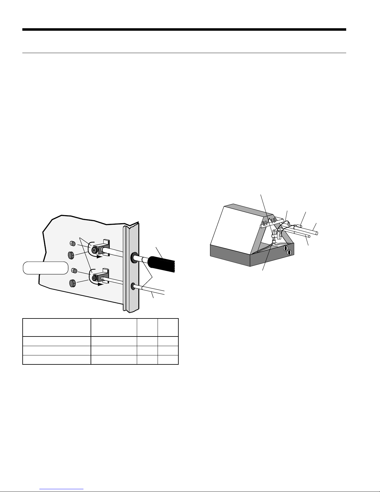
ASTON INDOOR SPLIT SERIES INSTALLATION MANUAL
Refrigeration
The indoor split series comes with a holding charge. The charge
must be adjusted in the field based on performance. Refrigeration
piping on the split consists of installing a brazed copper line
set between the blower coil unit and the unit’s split compressor
section. To select the proper tube diameters for the installation,
refer to the Line Set Sizes table. Line sets over 60 feet long are not
recommended because of oil return and pressure drop problems.
The suction line must always be insulated. Handle and route the
line sets carefully to avoid kinking or bending the tubes. If the line
set is kinked or distorted and it cannot be formed back into its
original shape, the bad portion of the pipe should be replaced. A
restricted line set will affect the performance of the system.
Fasten the copper line set to the blower coil unit as instructed
by the coil installation instructions shown in Figure 14. Nitrogen
should be bled through the system at 2 to 3 PSI to prevent
oxidation inside the refrigerant tubing. Use a low silver phoscopper braze alloy on all brazed connections.
Figure 13: Typical Split System Refrigerant Line Connections
Service ports for
attaching refrigerant
gauges
Insulated
Suction Line
The indoor split service valves are recessed in the unit’s corner post
and protected by a cover. Remove the protective cover and braze
the line set to the service valve stubs as shown in Figure 13. Care
should be used when brazing the service valves as to not scorch the
paint. Nitrogen should be bled through the system at 2 to 3 psi to
prevent oxidation contamination. Use a low silver phos-copper braze
alloy on all brazed connections. Indoor split units are shipped with a
factory charge and service valves are not to be opened until the line
set has been leak tested, purged, and evacuated. Schrader cores
should be removed before brazing, and replaced after the valves
have cooled. A heat sink should be used on the service valve and
TXV to prevent damage caused by excessive heat. When brazing is
completed, reinstall the protective cover.
Figure 14: Attaching the Air Coil
TXV ("IN" toward condensing unit)
Equalizer
Bulb
Suction
Liquid
ccw
ccw
Braze
Connection
Liquid
Line
Replace caps after
opening system
Position Description System
CW - Full In Shipping Position Closed Open
CCW - Full Out 1/2 turn CW Service Position Open Open
CCW - Full Out Operation Position Open Closed
TXV has internal check valve
Service
Port
28
Page 29

Refrigeration cont.
ASTON INDOOR SPLIT SERIES INSTALLATION MANUAL
Leak Testing
The refrigeration line set must be pressurized and checked for
leaks before purging and charging the unit. To pressurize the line
set, attach refrigerant gauges to the service ports and add an inert
gas (nitrogen or dry carbon dioxide) until pressure reaches 60 to
90 PSIG. Never use oxygen or acetylene to pressure test. Use an
electronic leak detector or a good quality bubble solution to detect
leaks on all connections made in the field. Check the service
valve ports and stem for leaks and all connections made in the
field. If a leak is found, repair it and repeat the above steps. For
safety reasons do not pressurize the system above 150 psi. Purge
pressure from line set. The system is now ready for evacuating
and charging.
System Evacuation
Ensure that the line set and air coil are evacuated before opening
service valves to the split unit. The line set must be evacuated to at
least 200 microns to remove the moisture and air that may still be
in the line set and coil. Evacuate the system through both service
ports to prevent false readings on the gauge because of pressure
drop through service ports.
Charge Amount When Using GAH Air Handler
The Aston Series Split is shipped with a factory pre-charge.
This volume of refrigerant is not sufficient to run the system and
additional refrigerant must be added. If using an GAH Air Handler
please refer to the Line Set Sizes table for charge amounts to
be added. The “Factory Charge” column is the charge amount
the compressor section/split is shipped with from the factory. The
“Charge Amount with GAH Air Handler” column is the total amount
of charge for the GAH Air Handler + Compressor section/split. This
column does not factor in additional refrigerant needed for the line
set. The installer of the system must add charge appropriately for
the specific length of the line set. A 3/8 in. liquid line is calculated
at 0.50 oz. of charge per linear foot, and a 1/2 in. liquid line
is calculated at 1.0 oz. of charge per linear foot using R-410A
refrigerant. The suction line will not hold “liquid” and should be
ignored for the charge calculation.
Example: 103*036/GAH036 with 20 ft. of 3/8 in. liquid line.
Remember that when using the GAH Air Handler, the
column “Charge Amount with GAH Air Handler” will be
used. Now calculate for the additional 20 ft. line set.
Additional refrigerant to be added = (20 ft. x 0.5 oz.)
= 10 oz.
Solution: 10 oz. should be added to the recommended charge
of 86 oz. found in the “Charge Amount with GAH Air
Handler” column for a total charge of 96 oz.
After initial charge, the system should be operated and the
system subcooling and superheat verified to the Unit Operating
Parameters table.
If an air handler manufactured by others is used then refrigerant
should be added to the Aston Series Split factory pre-charge.
Refrigerant should be added for liquid line length. This should
result in a slightly under-charged system exhibiting low subcooling
and high superheat. As charge is added, the subcooling should
rise and the superheat should fall.
Charging the System
Charge Method – After purging and evacuating the line set, fully
open the service valves counterclockwise. Add R-410A (liquid)
into the liquid line service port until the pressure in the system
reaches approximately 200 PSIG. Never add liquid refrigerant
into the suction side of a compressor. Start the unit and measure
superheat and subcooling. Keep adding refrigerant until the unit
meets the superheat and subcooling values on the Operating
Parameters tables.
Checking Superheat and Subcooling
Determining Superheat
1. Measure the temperature of the suction line at the point where
the expansion valve bulb is clamped.
2. Determine the suction pressure in the suction line by
attaching refrigeration gauges to the Schrader connection on
the suction side of the compressor.
3. Convert the pressure obtained in Step 2 to the saturation
temperature by using the R-410A Pressure/Temperature
Conversion Chart.
4. Subtract the temperature obtained in Step 3 from Step 1. The
difference is the amount of superheat for the unit. Refer to the
Operating Parameters tables for superheat ranges at specific
entering water conditions.
Superheat Adjustment
TXVs are factory set to a specific superheat; however, the
superheat should be adjusted for the application. To adjust the
TXV to other superheat settings:
1. Remove the seal cap from the bottom of the valve.
2. Turn the adjustment screw clockwise to increase superheat
and counterclockwise to decrease superheat. One complete
360° turn changes the superheat approximately 3-4°F,
regardless of refrigerant type. You may need to allow as much
as 30 minutes after the adjustment is made for the system to
stabilize.
3. Once the proper superheat setting has been achieved,
replace and tighten the seal cap.
WARNING: There are 8 total (360°) turns on the
superheat adjustment stem from wide open to
fully closed. When adjusting the superheat stem
clockwise (superheat increase) and the stop is
reached, any further clockwise turning adjustment
will damage the valve.
29
Page 30
ASTON INDOOR SPLIT SERIES INSTALLATION MANUAL
Refrigeration cont.
Determining Subcooling
1. Measure the temperature of the liquid line on the small refrigerant
line (liquid line) just outside the split cabinet. This location
will be adequate for measurement in both modes unless a
significant temperature drop in the liquid line is anticipated.
2. Measure the liquid line pressure by attaching refrigerant
gauges to the Schrader connection on the liquid line service
valve.
3. Convert the pressure obtained in Step 2 to the saturation
temperature by using the R-410A Pressure/Temperature
Conversion Chart.
4. Subtract the temperature in Step 1 from the temperature in
Step 3. The difference will be the subcooling value for that
unit. Refer to the Operating Parameters tables for subcooling
ranges at specific enter water conditions.
Line Set Sizes
Unit
Size
022 GAH022 5/8” OD 3/8” OD 5/8” OD 3/8” OD 3/4” OD 3/8” OD 56 78
030 GAH030 5/8” OD 3/8” OD 3/4” OD 3/8” OD 3/4” OD 3/8” OD 56 78
036 GAH036 5/8” OD 3/8” OD 3/4” OD 3/8” OD 3/4” OD 1/2” OD 56 86
042 GAH042 3/4” OD 3/8” OD 3/4” OD 3/8” OD 7/8” OD 1/2” OD 74 99
048 GAH048 3/4” OD 3/8” OD 7/8” OD 3/8” OD 7/8” OD 1/2” OD 90 115
060 GAH060 7/8” OD 1/2” OD 7/8” OD 1/2” OD 1-1/8” OD 1/2” OD 92 112
070 GAH060 7/8” OD 1/2” OD 7/8” OD 1/2” OD 1-1/8” OD 1/2” OD 108 132
026 GAH026 5/8” OD 3/8” OD 3/4” OD 3/8” OD 3/4” OD 1/2” OD 52 74
038 GAH036 3/4” OD 3/8” OD 3/4” OD 3/8” OD 3/4” OD 1/2” OD 56 86
049 GAH048 3/4” OD 3/8” OD 7/8” OD 3/8” OD 7/8” OD 1/2” OD 90 115
064 GAH060 7/8” OD 1/2” OD 7/8” OD 1/2” OD 1-1/8” OD 1/2” OD 92 112
072 GAH060 7/8” OD 1/2” OD 7/8” OD 1/2” OD 1-1/8” OD 1/2” OD 104 132
NOTES: * The "Charge Amount with GAH Air Handler" column is based on the charge amount for a GAH Air Handler+Compressor Section/Split.
Additional charge will have to be added accordingly for line set length.
After Charge is added adjustments can be made to get appropriate subcooling and superheat.
Additional charge for R-410A is 0.50 oz. per ft. for 3/8 in. and 1.0 oz. per ft. for 1/2 in. tube.
Air
Handler
20 feet 40 feet 60 feet
Suction Liquid Suction Liquid Suction Liquid
Factory
Charge (oz.)
*Charge Amount
with GAH Air
Handler (oz.)
4/6/10
30
Page 31
ASTON INDOOR SPLIT SERIES INSTALLATION MANUAL
Pressure/Temperature Conversion Chart for R-410A
PRESSURE
(PSIG)
TEMP
°F
PRESSURE
(PSIG)
TEMP
°F
PRESSURE
(PSIG)
TEMP °FPRESSURE
(PSIG)
TEMP
°F
PRESSURE
(PSIG)
60 8.5 180 63.5 300 96.3 420 120.6 540 140.0
62 9.9 182 64.2 302 96.8 422 120.9 542 140.3
64 11.2 184 64.8 304 97.2 424 121.3 544 140.6
66 12.5 186 65.5 306 97.7 426 121.6 546 140.9
68 13.8 188 66.1 308 98.1 428 122.0 548 141.2
70 15.1 190 66.8 310 98.6 430 122.3 550 141.4
72 16.3 192 67.4 312 99.0 432 122.7 552 141.7
74 17.5 194 68.0 314 99.5 434 123.0 554 142.0
76 18.7 196 68.7 316 99.9 436 123.4 556 142.3
78 19.8 198 69.3 318 100.4 438 123.7 558 142.6
80 21.0 200 69.9 320 100.8 440 124.1 560 142.9
82 22.1 202 70.5 322 101.2 442 124.4 562 143.2
84 23.2 204 71.1 324 101.7 444 124.8 564 143.5
86 24.3 206 71.7 326 102.1 446 125.1 566 143.7
88 25.4 208 72.3 328 102.5 448 125.4 568 144.0
90 26.5 210 72.9 330 103.0 450 125.8 570 144.3
92 27.5 212 73.5 332 103.4 452 126.1 572 144.6
94 28.6 214 74.1 334 103.8 454 126.5 574 144.9
96 29.6 216 74.7 336 104.2 456 126.8 576 145.1
98 30.6 218 75.3 338 104.7 458 127.1 578 145.4
100 31.6 220 75.8 340 105.1 460 127.5 580 145.7
102 32.6 222 76.4 342 105.5 462 127.8 582 146.0
104 33.5 224 77.0 344 105.9 464 128.1 584 146.2
106 34.5 226 77.5 346 106.3 466 128.5 586 146.5
108 35.4 228 78.1 348 106.7 468 128.8 588 146.8
110 36.4 230 78.7 350 107.2 470 129.1 590 147.1
112 37.3 232 79.2 352 107.6 472 129.4 592 147.3
114 38.2 234 79.8 354 108.0 474 129.8 594 147.6
116 39.1 236 80.3 356 108.4 476 130.1 596 147.9
118 40.0 238 80.9 358 108.8 478 130.4 598 148.2
120 40.9 240 81.4 360 109.2 480 130.7 600 148.4
122 41.7 242 81.9 362 109.6 482 131.1 602 148.7
124 42.6 244 82.5 364 110.0 484 131.4 604 149.0
126 43.4 246 83.0 366 110.4 486 131.7 606 149.2
128 44.3 248 83.5 368 110.8 488 132.0
608 149.5
130 45.1 250 84.1 370 111.2 490 132.3
132 45.9 252 84.6 372 111.6 492 132.7
134 46.7 254 85.1 374 112.0 494 133.0
136 47.5 256 85.6 376 112.3 496 133.3
138 48.3 258 86.1 378 112.7 498 133.6
140 49.1 260 86.6 380 113.1 500 133.9
142 49.9 262 87.1 382 113.5 502 134.2
144 50.7 264 87.7 384 113.9 504 134.5
146 51.5 266 88.2 386 114.3 506 134.9
148 52.2 268 88.7 388 114.7 508 135.2
150 53.0 270 89.2 390 115.0 510 135.5
152 53.7 272 89.6 392 115.4 512 135.8
154 54.5 274 90.1 394 115.8 514 136.1
156 55.2 276 90.6 396 116.2 516 136.4
158 55.9 278 91.1 398 116.5 518 136.7
160 56.6 280 91.6 400 116.9 520 137.0
162 57.4 282 92.1 402 117.3 522 137.3
164 58.1 284 92.6 404 117.6 524 137.6
166 58.8 286 93.0 406 118.0 526 137.9
168 59.5 288 93.5 408 118.4 528 138.2
170 60.2 290 94.0 410 118.7 530 138.5
172 60.8 292 94.5 412 119.1 532 138.8
174 61.5 294 94.9 414 119.5 534 139.1
176 62.2 296 95.4 416 119.8 536 139.4
178 62.9 298 95.8 418 120.2 538 139.7
TEMP
°F
31
Page 32

ASTON INDOOR SPLIT SERIES INSTALLATION MANUAL
Unit Startup
Before Powering Unit, Check the Following:
NOTE: Remove and discard the compressor hold down shipping
bolt located at the front of the compressor mounting bracket.
• High voltage is correct and matches nameplate.
• Fuses, breakers and wire size correct.
• Low voltage wiring complete.
• Piping completed and water system cleaned and flushed.
• Air is purged from closed loop system.
• Isolation valves are open, water control valves or loop
pumps wired.
• Condensate line open and correctly pitched.
• Transformer switched to 208V if applicable.
• Dip switches are set correctly.
• Hot water generator pump switch is “OFF” unless piping is
completed and air has been purged.
• Blower rotates freely.
• Blower speed is correct.
• Air filter/cleaner is clean and in position.
• Service/access panels are in place.
• Return air temperature is between 50-80°F heating and
60-95°F cooling.
• Check air coil cleanliness to ensure optimum performance.
Clean as needed according to maintenance guidelines. To
obtain maximum performance the air coil should be cleaned
before startup. A 10% solution of dishwasher detergent and
water is recommended for both sides of coil, a thorough water
rinse should follow.
Startup Steps
NOTE: Complete the Equipment Start-Up/Commissioning Check
Sheet during this procedure. Refer to thermostat operating
instructions and complete the startup procedure. Verify that the
compressor shipping bolt has been removed.
1. Initiate a control signal to energize the blower motor.
2. Initiate a control signal to place the unit in the
cooling mode. Cooling setpoint must be set below
room temperature.
3. First stage cooling will energize after a time delay.
4. Be sure that the compressor and water control valve or loop
pump(s) are activated.
5. Verify that the water flow rate is correct by measuring the
pressure drop through the heat exchanger using the P/T plugs
and comparing to unit performance data in catalog.
6. Check the temperature of both the supply and discharge water
(see the Unit Operating Parameters tables).
7. Check for an air temperature drop of 15°F to 25°F across
the air coil, depending on the fan speed and entering water
temperature.
8. Decrease the cooling set point several degrees and verify high-
speed blower operation.
9. Adjust the cooling setpoint above the room temperature and verify
that the compressor and water valve or loop pumps deactivate.
10. Initiate a control signal to place the unit in the heating mode.
Heating set point must be set above room temperature.
11. First stage heating will energize after a time delay.
12. Check the temperature of both the supply and discharge water
(see the Unit Operating Parameters tables).
13. Check for an air temperature rise of 12°F to 35°F across the air
coil, depending on the fan speed and entering water temperature.
14. If auxiliary electric heaters are installed, increase the heating
setpoint until the electric heat banks are sequenced on. All
stages of the auxiliary heater should be sequenced on when the
thermostat is in the Emergency Heat mode. Check amperage of
each element.
15. Adjust the heating setpoint below room temperature and verify
that the compressor and water valve or loop pumps deactivate.
16. During all testing, check for excessive vibration, noise or water
leaks. Correct or repair as required.
17. Set system to desired normal operating mode and set
temperature to maintain desired comfort level.
18. Instruct the owner/operator in the proper operation of the
thermostat and system maintenance.
NOTES: Be certain to fill out and forward all warranty
registration papers.
Final Evaluation
After the initial check of superheat/subcooling values in the
heating mode, shut off the unit and allow it to sit 3 to 5 minutes
until pressures equalize. Restart the unit in the cooling mode
and check the values against those in the Operating Parameters
tables. If the unit performs satisfactorily, charging is complete. If
the unit does not perform to specifications, the charge may need
to be readjusted until the values are close. Adding refrigerant
will increase subcooling. Recovering some of the refrigerant will
decrease subcooling and increase superheat. If the superheat/
subcooling values are still not close to the specifications in the
Operating Parameters tables, analyze refrigerant circuit operation.
32
Page 33
Operating Parameters
Single Speed Models - 103*022 thru 103*070
(with GAH Series Air Handler)
ASTON INDOOR SPLIT SERIES INSTALLATION MANUAL
Entering Water
Temp °F
50
70
90
Entering Water
Temp °F
30
50
70
NOTES: Cooling performance based on entering air temperatures of 80°F DB, 67°F WB.
Heating performance based on entering air temperatures of 70°DB.
Water
Flow GPM/
Ton
1.5 115-150 205-245 115-130 205-245 12-22 7-14 5-22 18-24
3.0 110-145 200-235 110-125 200-235 14-26 6-12 8-12 18-24
1.5 125-160 260-300 125-160 275-300 8-14 8-12 5-19 18-22
3.0 115-150 265-295 115-135 265-295 9-16 4-16 5-12 18-22
1.5 125-160 320-370 125-160 330-370 8-14 6-13 14-22 18-22
3.0 120-150 305-355 120-150 325-365 9-16 4-16 5-12 18-22
Water
Flow GPM/
Ton
1.5 65-85 290-310 65-85 330-360 7-13 2-21 7-10 18-24
3.0 70-90 265-330 70-90 335-365 6-12 2-21 3-7 22-26
1.5 95-120 320-345 95-120 395-430 6-12 2-21 5-11 21-34
3.0 100-125 280-365 100-125 375-405 6-12 4-22 5-11 24-33
1.5 135-155 315-380 135-155 435-485 8-14 10-20 8-14 26-46
3.0 135-156 315-395 135-155 440-490 8-14 10-20 3-10 25-48
103*022 thru 103*060 103*070 103*022 thru 103*070
Suction
Pressure PSIG
103*022 thru 103*060 103*070 103*022 thru 103*070
Suction
Pressure PSIG
Discharge
Pressure PSIG
Discharge
Pressure PSIG
Cooling -- No Hot Water Generator
Suction
Pressure PSIG
Heating -- No Hot Water Generator
Suction
Pressure PSIG
Discharge
Pressure PSIG
Discharge
Pressure PSIG
Superheat Subcooling
Superheat Subcooling
Water Temp
Rise °F
Water Temp
Drop °F
Air Temp Drop
°F DB
Air Temp Rise
°F DB
5/29/08
33
Page 34

ASTON INDOOR SPLIT SERIES INSTALLATION MANUAL
Operating Parameters cont.
103*026 thru 103*072 (with GAH Series Air Handler)
First Stage Operation
Cooling -- No Hot Water Generator
Suction
Pressure
PSIG
Heating -- No Hot Water Generator
Suction
Pressure
PSIG
Discharge
Pressure
PSIG
Discharge
Pressure
PSIG
Entering Water
Temp °F
50
70
90
Entering Water
Temp °F
30
50
70
Water Flow
GPM/Ton
1.5 130-150 193-230 130-150 200-245 8-16 7-14 7-20 18-24
3.0 128-153 190-230 125-140 205-240 8-16 3-10 9-14 18-25
1.5 130-150 238-282 135-150 240-280 6-16 4-16 9-18 18-25
3.0 130-155 238-262 125-145 245-270 6-18 5-11 5-10 18-24
1.5 133-148 308-340 130-155 300-365 7-16 6-18 4-11 19-25
3.0 138-153 303-333 130-165 305-350 7-18 7-14 5-9 17-22
Water Flow
GPM/Ton
1.5 78-100 275-325 85-105 325-385 6-11 4-16 2-8 20-29
3.0 78-110 285-325 90-120 335-375 6-11 4-16 3-7 20-32
1.5 105-120 305-350 100-130 340-400 5-12 4-16 5-12 24-32
3.0 110-125 305-355 110-125 345-395 9-15 2-14 4-9 20-34
1.5 140-155 305-355 130-165 370-430 5-12 2-14 8-12 24-39
3.0 145-160 330-360 140-160 375-425 7-17 7-15 4-9 24-39
103*026 thru 103*064 103*072 103*026 thru 103*072
Suction
Pressure
PSIG
103*026 thru 103*064 103*072 103*026 thru 103*072
Suction
Pressure
PSIG
Discharge
Pressure
PSIG
Discharge
Pressure
PSIG
Superheat Subcooling
Superheat Subcooling
Water Temp
Rise °F
Water Temp
Drop °F
Air Temp Drop
°F DB
Air Temp Rise
°F DB
Second Stage Operation
Entering Water
Temp °F
50
70
90
Entering Water
Temp °F
30
50
70
NOTES: Cooling performance based on entering air temperatures of 80°F DB, 67°F WB.
Heating performance based on entering air temperatures of 70°DB.
Water Flow
GPM/Ton
1.5 120-140 200-245 105-150 210-270 7-17 6-14 7-16 19-26
3.0 115-140 195-290 110-130 215-260 7-15 4-11 8-12 20-24
1.5 121-136 265-310 105-150 280-350 9-15 6-18 7-15 19-25
3.0 123-139 265-310 110-140 285-320 10-16 8-16 8-12 18-24
1.5 122-140 310-360 115-140 325-385 8-14 6-18 10-16 18-24
3.0 123-139 310-350 120-135 330-355 8-14 7-15 8-12 17-23
Water Flow
GPM/Ton
1.5 72-89 295-350 70-100 320-370 7-18 10-20 4-13 18-24
3.0 73-87 305-330 75-90 315-365 7-18 10-20 4-16 18-27
1.5 100-120 320-365 95-130 375-430 6-14 6-18 4-10 23-34
3.0 105-120 355-365 100-125 370-420 6-14 6-18 4-9 20-37
1.5 142-158 360-380 130-165 400-470 6-12 4-15 6-15 28-38
3.0 138-152 365-390 135-160 405-465 7-14 4-15 6-12 24-42
103*026 thru 103*064 103*072 103*026 thru 103*072
Suction
Pressure
PSIG
103*026 thru 103*064 103*072 103*026 thru 103*072
Suction
Pressure
PSIG
Discharge
Pressure
PSIG
Discharge
Pressure
PSIG
Cooling -- No Hot Water Generator
Suction
Pressure
PSIG
Heating -- No Hot Water Generator
Suction
Pressure
PSIG
Discharge
Pressure
PSIG
Discharge
Pressure
PSIG
Superheat Subcooling
Superheat Subcooling
Water Temp
Rise °F
Water Temp
Drop °F
Air Temp Drop
°F DB
Air Temp Rise
°F DB
5/29/08
34
Page 35
ASTON INDOOR SPLIT SERIES INSTALLATION MANUAL
Pressure Drop
Single Speed Dual Capacity
Model GPM
3
022
030
036
042
048
060
070
4.5
6
8
4
6
8
10
5
7
9
12
5
8
11
14
6
9
12
16
9
12
15
20
12
15
18
24
Pressure Drop (PSI)
30°F 50°F 70°F 90°F 110°F
0.9
1.7
2.8
4.7
1.3
2.7
4.5
6.8
1.0
2.1
3.6
6.3
0.8
2.1
4.2
7.6
1.1
2.3
3.9
6.7
2.4
3.9
5.7
9.5
3.0
4.4
6.0
9.7
0.9
1.6
2.7
4.4
1.2
2.5
4.2
6.3
1.0
1.9
3.3
5.9
0.7
2.1
4.1
6.7
1.0
2.1
3.7
6.3
2.2
3.6
5.3
8.9
2.8
4.0
5.5
9.1
0.8
1.5
2.5
4.1
1.2
2.4
3.9
5.4
0.9
1.8
3.0
5.5
0.7
1.9
3.8
6.3
1.0
2.0
3.4
5.9
2.1
3.4
5.0
8.3
2.6
3.8
5.1
8.5
0.7
1.4
2.3
3.9
1.1
2.2
3.7
5.4
0.8
1.7
2.8
5.1
0.7
1.8
3.5
5.8
0.9
1.9
3.2
5.5
2.0
3.2
4.7
7.8
2.4
3.5
4.8
7.9
0.7
1.3
2.2
3.6
1.0
2.2
3.4
5.0
0.8
1.6
2.6
4.8
0.6
1.7
3.3
5.4
0.8
1.7
3.0
5.1
1.8
2.9
4.3
7.2
2.2
3.3
4.4
7.3
5/28/13
Model GPM
026
full
load
026
part
load
038
full
load
038
part
load
049
full
load
049
part
load
064
full
load
064
part
load
072
full
load
072
part
load
4
6
8
10
3
5
7
9
5
7
9
11
4
6
8
10
6
9
12
15
5
8
11
14
8
12
16
20
6
10
14
18
12
15
18
21
10
13
16
19
Pressure Drop (psi)
30°F 50°F 70°F 90°F 110°F
1.4
2.8
4.7
7.0
0.8
2.0
3.6
5.8
1.2
2.2
3.4
4.9
0.9
1.7
2.8
4.2
1.2
2.4
3.9
5.7
0.9
2.0
3.4
5.0
1.8
3.8
6.5
9.7
1.0
2.6
5.0
8.1
3.2
4.5
6.0
7.8
2.3
3.6
5.0
6.5
1.3
2.6
4.4
6.6
0.7
1.8
3.4
5.5
1.2
2.1
3.2
4.6
0.8
1.6
2.6
3.9
1.2
2.2
3.6
5.3
0.9
1.8
3.1
4.7
1.7
3.5
6.0
9.1
0.9
2.5
4.7
7.6
3.0
4.2
5.7
7.3
2.1
3.3
4.6
6.2
1.2
2.4
4.1
6.2
0.7
1.7
3.2
5.1
1.1
1.9
3.0
4.3
0.8
1.5
2.5
3.7
1.1
2.1
3.4
5.0
0.8
1.7
2.9
4.4
1.6
3.3
5.6
8.5
0.9
2.3
4.4
7.1
2.8
4.0
5.3
6.8
2.0
3.0
4.3
5.8
1.1
2.3
3.8
5.8
0.7
1.6
3.0
4.8
1.0
1.8
2.8
4.0
0.7
1.4
2.3
3.4
1.0
2.0
3.2
4.7
0.8
1.6
2.8
4.1
1.4
3.0
5.2
8.0
0.8
2.1
4.1
6.6
2.6
3.7
4.9
6.4
1.9
2.8
4.0
5.4
1.0
2.1
3.5
5.3
0.6
1.5
2.8
4.4
1.0
1.7
2.6
3.7
0.7
1.3
2.1
3.2
1.0
1.8
2.9
4.3
0.7
1.5
2.5
3.8
1.3
2.8
4.8
7.4
0.8
2.0
3.8
6.1
2.4
3.4
4.6
5.9
1.7
2.6
3.7
5.0
5/30/06
35
Page 36
ASTON INDOOR SPLIT SERIES INSTALLATION MANUAL
Refrigerant Circuit Guideline
Symptom
Under Charged System (Possible Leak) Low Low Low High Low Low Low
Over Charged System High High High Normal High Normal/Low Normal
Low Air Flow Heating High High High High/Normal Low High Low
Low Air Flow Cooling Low Low Low Low/Normal High High Low
Low Water Flow Heating Low/Normal Low/Normal Low Low High Low High
Low Water Flow Cooling High High High High Low Low High
High Air Flow Heating Low Low Low Low High Low Low
High Air Flow Cooling Low High Normal High Low Low Normal
High Water Flow Heating Normal Low Normal High Normal Normal Low
High Water Flow Cooling Low Low Low Low High Normal Low
Low Indoor Air Temperature Heating Low Low Low Normal High Normal Normal/High
Low Indoor Air Temperature Cooling Low Low Low Normal/Low High Low Low
High Indoor Air Temperature Heating High High High Normal/High Normal/Low Low Normal
High Indoor Air Temperature Cooling High High High High Low Low High
Restricted TXV (Check Service Advisory) High Low Normal/Low High High Low Low
Insufficient Compressor (Possible Bad Valves) Low High Low High Normal/High Low Low
TXV - Bulb Loss of Charge Low Low Low High High Low Low
Scaled Coaxial Heat Exchanger Heating Low Low Low Normal/Low High Low Low
Scaled Coaxial Heat Exchanger Cooling High High High Normal/Low Low Low Low
Restricted Filter Drier Check temperature difference (delta T) across filter drier.
Head
Pressure
Suction
Pressure
Compressor
Amp Draw
Superheat Subcooling
Air Temp.
Differential
Water Temp.
Differential
7/6/10
Thermistor Resistance
Thermistor Temperature (°F) Resistance in Ohms
78.5 9230 -10007
77.5 9460 - 10032
76.5 9690 - 10580
75.5 9930 - 10840
33.5 30490 - 32080
32.5 31370 - 33010
31.5 32270 - 33690
30.5 33190 - 34940
1.5 79110 - 83750
0.5 81860 - 86460
0.0 82960 - 87860
Compressor Resistance
Model
022 ZP16K5E-PFV 1.39 - 1.53 2.15 - 2.30
030 ZP21K5E-PFV 1.21 - 1.39 1.53 - 1.75
036 ZP25K5E-PFV 0.95 - 1.09 1.81 - 2.09
042 ZP31K5E-PFV 0.83 - 0.95 1.54 - 1.78
048 ZP38K5E-PFV 0.51 - 0.59 1.13 - 1.31
060 ZP51K5E-PFV 0.42 - 0.48 0.73 - 0.85
070 ZP57K5E-PFV 0.33 - 0.39 0.90 - 1.04
026 ZPS20K5E-PFV 1.21 - 1.39 1.52 - 1.75
038 ZPS30K5E-PFV 0.81 - 0.94 1.41 - 1.63
049 ZPS40K5E-PFV 0.48 - 0.55 1.72 - 1.99
064 ZPS51K5E-PFV 0.36 - 0.42 1.51 - 1.74
072 ZPS60K5E-PFV 0.31 - 0.36 1.72 - 1.98
Compressor
Model No.
208-230/60/1
Run Start
2/7/12
36
Page 37
ASTON INDOOR SPLIT SERIES INSTALLATION MANUAL
Heat of Extraction/Rejection Data - Dual Capacity Units
Model GPM
3.0 13.1 17.6 21.5 23.5 22.9 21.8
Part Load
026
Full Load
Part Load
038
Full Load
Part Load
049
Full Load
Part Load
064
Full Load
Part Load
072
Full Load
Note: operation not recommended in shaded areas. 1/14/2011
5.0 9.4 13.8 18.6 22.6 21.7 23.6 23.0 21.7 20.2
7.0 9.6 14.1 18.9 23.0 21.9 23.7 23.1 21.7 20.2
4.0 17.8 23.4 28.5 31.0 31.2 30.0
6.0 13.4 18.8 24.7 29.9 29.9 31.1 31.3 29.9 28.1
8.0 13.6 19.3 25.1 30.5 30.1 31.2 31.3 29.9 28.1
4.0 17.9 23.3 28.1 32.5 31.8 30.0
6.0 12.8 18.7 24.5 29.8 29.8 32.7 32.0 30.1 28.2
8.0 13.9 19.7 25.2 29.8 30.3 33.1 32.4 30.4 28.5
5.0 25.1 31..5 36.1 44.8 45.1 42.8
7.0 18.7 26.2 33.2 38.6 41.8 45.2 45.7 43.6 41.0
9.0 19.1 26.9 34.3 40.0 42.0 45.5 46.0 43.8 41.1
5.0 24.0 29.5 33.7 44.9 46.1 44.0
8.0 19.2 26.4 32.6 37.5 40.6 45.0 45.8 43.4 40.5
11.0 19.8 27.5 34.3 39.9 40.0 44.9 46.1 44.3 41.5
6.0 33.3 40.6 46.1 60.2 60.2 56.4
9.0 26.0 34.7 42.8 49.1 56.0 60.2 60.8 57.4 52.9
12.0 26.5 35.7 44.2 50.9 56.1 60.4 61.1 57.6 53.2
6.0 31.0 39.2 46.1 56.3 55.4 52.1
10.0 21.6 31.4 40.9 49.7 52.4 56.2 55.5 52.4 49.4
14.0 22.6 32.6 41.7 49.8 52.2 56.2 55.6 52.6 49.7
8.0 40.8 52.7 64.7 73.7 75.7 70.3
12.0 31.9 43.8 55.1 65.8 66.8 74.1 76.1 70.5 66.2
16.0 32.2 44.7 56.8 68.6 67.2 74.5 76.5 70.9 66.3
10.0 36.4 46.5 54.7 63.4 63.0 58.9
13.0 25.2 36.7 48.5 59.1 57.7 63.2 63.0 59.2 55.1
16.0 26.7 38.2 49.4 59.1 57.3 63.2 63.3 59.5 55.4
12.0 48.3 62.7 69.0 81.8 83.0 77.8
15.0 37.2 51.6 65.4 70.9 73.6 82.1 83.3 78.0 71.9
18.0 37.6 52.7 67.5 73.5 74.1 82.6 83.8 78.4 72.2
Heat of Extraction (kBtuh) Heat of Rejection (kBtuh)
30°F 50°F 70°F 90°F 30°F 50°F 70°F 90°F 110°F
37
Page 38
ASTON INDOOR SPLIT SERIES INSTALLATION MANUAL
Heat of Extraction/Rejection Data - Single Speed Units
Model GPM
3.0 13.6 18.0 22.0 25.6
022
030
036
042
048
060
070
Note: operation not recommended in shaded areas. 5/29/2013
4.5 9.9 14.3 19.1 23.0 23.3 25.8 25.5 23.5 22.3
6.0 10.0 14.8 19.4 23.5 23.5 26.0 25.5 23.6 22.4
4.0 19.2 25.0 29.8 31.2 31.5 29.8
6.0 14.0 19.8 26.0 31.0 29.0 31.1 31.4 29.7 26.4
8.0 14.2 20.4 26.5 32.5 29.3 31.4 31.6 29.9 26.5
5.0 23.6 31.0 37.2 38.6 39.7 36.7
7.0 17.5 24.7 32.3 38.8 32.1 38.5 39.6 36.6 35.7
9.0 17.9 25.2 32.9 39.4 32.5 38.9 39.9 36.8 35.9
5.0 26.9 33.4 36.6 46.7 47.6 43.9
8.0 20.8 28.2 35.1 42.0 43.1 46.9 47.9 44.2 42.3
11.0 21.2 29.0 36.2 43.5 43.4 47.2 48.2 44.4 43.1
6.0 34.7 43.5 50.7 57.6 57.5 51.3
9.0 26.5 36.3 45.8 53.8 53.4 57.8 57.9 51.7 51.6
12.0 27.0 37.3 47.2 55.6 53.7 58.1 58.0 51.8 51.6
9.0 41.0 52.4 61.2 75.4 74.0 68.9
12.0 28.9 42.3 54.1 65.0 72.9 75.6 74.3 68.7 64.9
15.0 30.0 43.2 56.3 65.8 73.5 75.7 73.9 68.9 67.0
12.0 50.3 64.2 70.3 82.9 84.1 74.7
15.0 36.4 51.6 67.0 74.6 75.9 83.0 82.2 74.4 70.7
18.0 36.6 52.1 68.1 76.3 76.3 83.6 83.1 75.2 71.4
Heat of Extraction (kBtuh) Heat of Rejection (kBtuh)
30°F 50°F 70°F 90°F 30°F 50°F 70°F 90°F 110°F
25.4 23.5
38
Page 39

Troubleshooting
ASTON INDOOR SPLIT SERIES INSTALLATION MANUAL
Aurora Control System
NOTE: Refer to the Aurora Base Control Application and
Troubleshooting Guide and the Instruction Guide: Aurora Interface and
Diagnostics (AID) Tool for additional information.
To check the unit control board for proper operation:
1. Disconnect thermostat wires at the control board.
2. Jumper the desired test input (Y1, Y2, W, O or G) to the R
terminal to simulate a thermostat signal.
3. If control functions properly:
• Check for thermostat and field control wiring (use
the diagnostic inputs mode).
4. If control responds improperly:
• Ensure that component being controlled is functioning
(compressor, blower, reversing valve, etc.).
• Ensure that wiring from control to the component
is correct.
• Refer to the Aurora Base Control Application and
Troubleshooting Guide and the Instruction Guide: Aurora
Interface and Diagnostics (AID) Tool for additional information.
Refrigerant Systems
To maintain sealed circuit integrity, do not install service gauges
unless unit operation appears abnormal. Compare the change in
temperature on the air side as well as the water side to the Unit
Operating Parameters tables. If the unit’s performance is not
within the ranges listed, and the airflow and water flow are known
to be correct, gauges should then be installed and superheat and
subcooling numbers calculated. If superheat and subcooling are
outside recommended ranges, an adjustment to the refrigerant
charge may be necessary.
NOTE:
Refrigerant tests must be made with hot water generator
turned “OFF”.
before servicing the refrigerant circuit.
Verify that air and water flow rates are at proper levels
39
Page 40
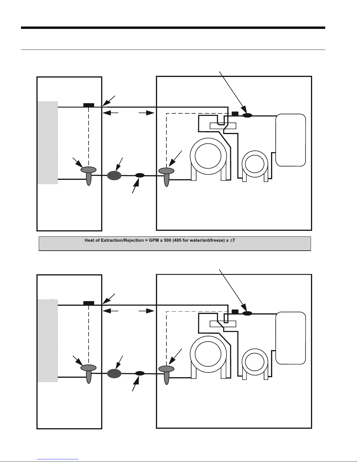
ASTON INDOOR SPLIT SERIES INSTALLATION MANUAL
Unit Startup/Troubleshooting
Heating Cycle Analysis
Measure suction
temperature here
at TXV bulb in
cooling modes.
Air
Coil
ClgTXV
COOLING TXV - ACTIVE
RIGHT TO LEFT
filter/drier
Measure liquid line
temperature and
pressure here in
both heating and
cooling modes
Lineset
length
Bi-flow
Measure suction temperature
here at TXV bulb in heating modes.
Volts ____
Amps ____
HtgTXV
COAX
EWT ____
LWT ____
HEATING TXV - ACTIVE LEFT TO RIGHT
Suct PSI____
Suct sat temp____
Suct temp____
Super heat____
Suction
Comp
Discharge
Hot Water
Generator
Discharge PSI____
Disch. sat temp____
Liquid temp____
Sub cooling____
Note: DO NOT hook up pressure gauges unless there appears to be a performance problem.
Cooling Cycle Analysis
Measure suction
temperature here
at TXV bulb in
cooling modes.
Air
Coil
ClgTXV
COOLING TXV - ACTIVE
RIGHT TO LEFT
filter/drier
Measure liquid line
temperature and
pressure here in
both heating and
cooling modes
Lineset
length
Bi-flow
Measure suction temperature
here at TXV bulb in heating modes.
Volts ____
Amps ____
HtgTXV
COAX
EWT ____
LWT ____
HEATING TXV-ACTIVE LEFT TO RIGHT
Suct PSI ____
Suct sat temp ____
Suct temp ____
Super heat ____
Suction
Comp
Discharge
Hot Water
Generator
Discharge PSI ____
Disch. sat temp ____
Liquid temp ____
Sub cooling ____
40
Page 41
ASTON INDOOR SPLIT SERIES INSTALLATION MANUAL
Troubleshooting cont.
Single Speed/Dual Capacity Startup/Troubleshooting Form
1. Job Information
Model # Job Name: Loop: Open / Closed
Serial # Install Date: Hot Water Generator: Y / N
2. Flow Rate in gpm SOURCE COAX LOAD COAX (Water-to-Water)
HEATING COOLING HEATING COOLING
WATER IN Pressure:
WATER OUT Pressure:
Pressure Drop: a - b
Look up flow rate in table:
3. Temp. Rise/Drop Across Coaxial Heat Exchanger
WATER IN Pressure:
WATER OUT Pressure:
Temperature Difference:
4. Temp. Rise/Drop Across Air Coil SOURCE COAX LOAD COAX (Water-to-Water)
SUPPLY AIR Temperature:
RETURN AIR Temperature:
Temperature Difference:
5. Heat of Rejection (HR)/Heat of Extraction (HE)
Brine Factor
2
: k.
HR/HE = d x g x k
STEPS 6-9 NEED ONLY BE COMPLETED IF A PROBLEM IS SUSPECTED.
6. Watts ENERGY MONITOR
Volts:
Total Amps (Comp. + Blower)
3
: n. Amps n. Amps
Watts = m x n x 0.85:
7. Capacity
Cooling Capacity = l - (o x 3.413):
Heating Capacity = l + (o x 3.413):
8. Efficiency
Cooling EER = p / o:
Heating COP = p / (o x 3.413):
9. Superheat (S.H.)/Subcooling (S.C.)
Suction Pressure:
Suction Saturation Temperature:
Suction Line Temperature:
S.H. = t - s
Head Pressure:
High Pressure Saturation Temp:
4
Liquid Line Temperature
: x. °F x. °F
S.C. = w - x
1
NOTES:
2
Steps 3-9 should be conducted with the hot water generator disconnected.
Use 500 for pure water, 485 for methanol or Environol™. (This constant is derived by multiplying the weight of one gallon of water (8.34) times the minutes
in one hour (60) times the specific heat of the fluid. Water has a specific heat of 1.0.
3
4
If there is only one source of power for the compressor and blower, amp draw can be measured at the source wiring connection.
Liquid line is between the coax and the expansion device in the cooling mode; between the air coil and the expansion device in the heating mode.
a. psi a. psi a. psi a. psi
b. psi b. psi b. psi b. psi
c. psi c. psi c. psi c. psi
d. gpm d. gpm d. gpm d. gpm
1
HEATING COOLING
e. °F e. °F
f. °F f. °F
g. °F g. °F
HEATING COOLING HEATING COOLING
h. °F h. °F h. °F h. °F
i. °F i. °F i. °F i. °F
j. °F j. °F j. °F j. °F
HEATING COOLING
l. Btu/h l. Btu/h
HEATING COOLING
m. Volts m. Volts
o. Watts o. Watts
HEATING COOLING
p. Btu/h p. Btu/h
HEATING COOLING
q. Btu/h q. Btu/h
HEATING COOLING
r. psi r. psi
s. °F s. °F
t. °F t. °F
u. °F u. °F
Software Version
ABC:
AXB:
IZ2:
T’STAT:
v. psi v. psi
w. °F w. °F
y. °F y. °F
41
Page 42

ASTON INDOOR SPLIT SERIES INSTALLATION MANUAL
Preventive Maintenance
Water Coil Maintenance
1. Keep all air out of the water. An open loop system should be
checked to ensure that the well head is not allowing air to
infiltrate the water line. Lines should always be airtight.
2. Keep the system under pressure at all times. It is
recommended in open loop systems that the water control
valve be placed in the discharge line to prevent loss of
pressure during off cycles. Closed loop systems must have
positive static pressure.
NOTE: On open loop systems, if the installation is in an area with
a known high mineral content (125 PPM or greater) in the water,
it is best to establish with the owner a periodic maintenance
schedule so the coil can be checked regularly. Should periodic
coil cleaning be necessary, use standard coil cleaning procedures
which are compatible with either the cupronickel or copper water
lines. Generally, the more water flowing through the unit the less
chance for scaling.
Other Maintenance
Filters
Filters must be clean to obtain maximum performance. They
should be inspected monthly under normal operating conditions
and be replaced when necessary. Units should never be operated
without a filter.
Condensate Drain
In areas where airborne bacteria produce a slime in the drain pan,
it may be necessary to treat chemically to minimize the problem.
The condensate drain can pick up lint and dirt, especially with dirty
filters. Inspect twice a year to avoid the possibility of overflow.
Blower Motors
ECM blower motors are equipped with sealed ball bearings and
require no periodic oiling.
Hot Water Generator Coil
See Water Coil Maintenance section above.
Air Coil
The air coil must be cleaned to obtain maximum performance.
Check once a year under normal operating conditions and, if dirty,
brush or vacuum (with a brush attachment) clean. Care must be
taken not to damage the aluminum fins while cleaning.
Replacement Procedures
Obtaining Parts
When ordering service or replacement parts, refer to the model
number and serial number of the unit as stamped on the serial
plate attached to the unit. If replacement parts are required, mention the date of installation of the unit and the date of failure, along
with an explanation of the malfunctions and a description of the
replacement parts required.
CAUTION: Fin edges are sharp.
In-Warranty Material Return
Material may not be returned except by permission of authorized
warranty personnel. Contact your local distributor for warranty
return authorization and assistance.
42
Page 43
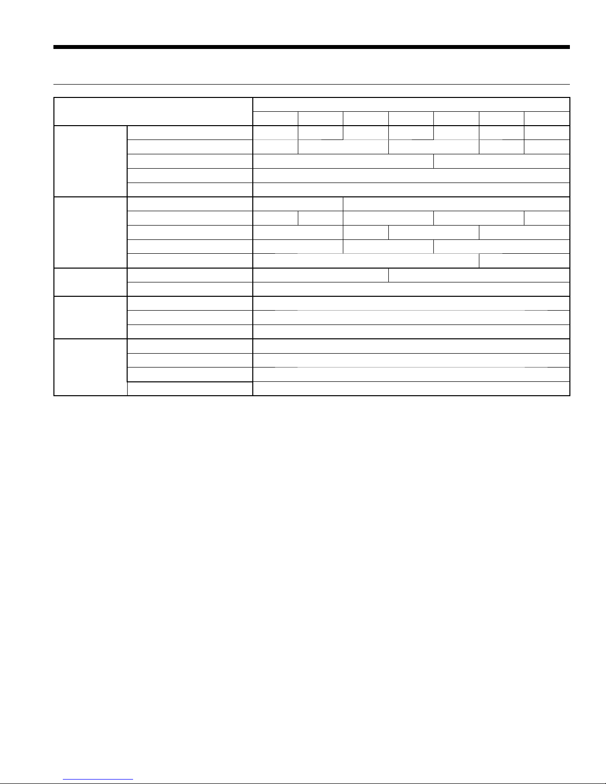
ASTON INDOOR SPLIT SERIES INSTALLATION MANUAL
Service Parts List
Single Speed Split Units
022 030 036 042 048 060 070
Compressor 34P581-01 34P582-01 34P583-01 34P578-01 34P579-01 34P580-01 34P646-01
Run Capacitor 16P002-18 16P002-20 16P002-21 16P002-25 16P002-41
Compressor
Refrigeration
Components
Desuperheater
Electrical
Sensors & Safeties
Part numbers subject to change 10/09/13
Sound Jacket 92P504A05 92P504A16
Power Harness 11P781-01
Solenoid Harness N / A
Accumulator 36P509-02 36P509-01
Coax 62I594-01 62I588-01 62I542B01 62I543B01 62I555-01
TXV 33P609-01 33P609-03 33P609-05 33P609-06
Reversing Valve 33P506-04 33P503-05 33P526-05
Filter Dryer 36P500B01 36P500B02
Desuperheater 62P516-05 62P516-03
Desuperheater Pump 24P501-02
Contactor 13P004A03
2 Pole Screw Term. Block 12P500A01
ABC Board 17X553-00
Freeze Protection Thermistor 12P505-09
HWL Thermistor 13P073B05
High Pressure Switch SKHPE600
Low Pressure Switch SKLPE40
43
Page 44
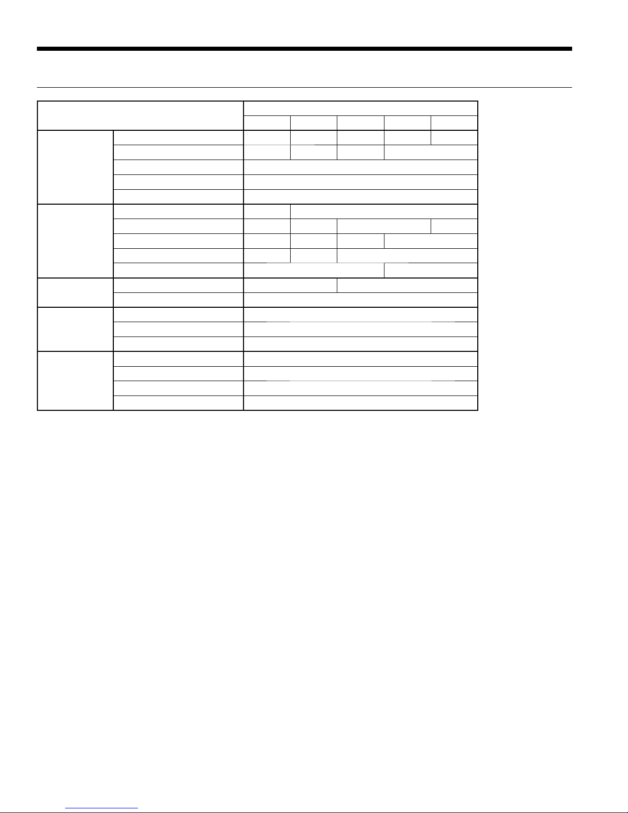
ASTON INDOOR SPLIT SERIES INSTALLATION MANUAL
Service Parts List cont.
Parts List
Compressor 34P640-01 34P641-01 34P642-01 34P643-01 34P644-01
Run Capacitor 16P002-19 16P002-20 16P002-18 16P002-31
Compressor
Refrigeration
Components
Desuperheater
Electrical
Sensors & Safeties
Part numbers subject to change 10/09/13
Sound Jacket 92P504A16
Power Harness 11P781-01
Solenoid Harness 11P782-02
Accumulator 36P509-02 36P509-01
Coax 62P594-01 62I54201 62P543B01 62P555-01
TXV 33P609-01 33P609-03 33P609-05 33P609-06
Reversing Valve 33P506-04 33P503-05 33P526-05
Filter Dryer 36P500B01 36P500B02
Desuperheater 62P516-05 62P516-03
Desuperheater Pump 24P501-02
Contactor 13P004A03
2 Pole Screw Term. Block 12P500A01
ABC Board 17X553-00
Freeze Protection Thermistor 12P505-09
HWL Thermistor 13P073B05
High Pressure Switch SKHPE600
Low Pressure Switch SKLPE40
026 038 049 064 072
Dual Capacity Split Units
44
Page 45

Notes
ASTON INDOOR SPLIT SERIES INSTALLATION MANUAL
45
Page 46

ASTON INDOOR SPLIT SERIES INSTALLATION MANUAL
Revision Guide
Pages: Description: Date: By:
All First Published 14 Oct 2013 DS
46
Page 47

Page 48

©2013 The manufacturer has a policy of continual product research and development and reserves the right to change design and specifi cations without notice.
Product: Aston Series
Type: Indoor Split Geothermal/Water Source
Heat Pump
Size: 2-6 Ton Single & Two-Stage
Document Type: Installation Manual
Part Number: IM2503SG
Release Date: 10/13
 Loading...