

Geospace vlf 12 schematic
,-
\--
.-f
DEPARIMENT
DEPARTMENT
DEPARTMENT
I
oFTHE ARMY TEcHNIcAt,VIANUAI
IHE
OF
OF IHE
OPERATOR,
GBIIRAI. SUPPORT, AND DEPOT MAhTTENAI{CE
NAVY TECHNICAL
AtR FORCE TECHNICAL
ORGANIZATrcNAI., DIRTCT SUPFORT,
MANUAT
ORDER
Trrt I t-5895-4t3-t5/3
NAVSH'IPS
T0
0967-30t-5230
3rs5-2rYQ42-r6r
TIANUA1
-f
REGEIVER.PHASE
COMPARAT(IR
J-
.l
CM.364IG
\-_
DEPARTilEIIS OT THE
ARTIY, THE NAW
OCIO.BER 1968
AND
T}IE
AIR FORC
?i^
I I
-5895-413-1
5/3/NAVSH|P5
O967-3ol-523OItO 3155-2FyQ42-t6l
TECHNICAL
No.
11-5895-413-15/3
TECHNICAL
NAVSHTPS
TECHNICAL
TO
31S5-2FYQ42-161
CHAPTEB
Section
1. INTRO
f, General
II. Description and
CHAPIER
Section
CHAPTEB
Section
2. INSTALLATION
I. Installation
3. PRINCIPLES
I. General
IL
III. Individual
MANUAL
MANUAL
0967-301*5230
ORDER
Operotor,
RECEIVER-PHAsE
DUCTION
Scope
Indexes of equipment
Forms
and records
data
Major
components
Uses and
VLF tihe
Technical
Physical
Generel
Unpacking
Tools
Installation procedure
Operation
Generial
Preoperational
Utilizing the vlf-12B
Stopping
Introduction
Functional
Simplified
Detailed
General
Local
Second
Mechanical
Basic
Power
Plus
capabilities
service stations
characteristics
description
AND OPERATION
and
and equipment
description
block description
oscillat r synthesizer
mixer
si8nal
control
20-volt
checking the equipment
procedure
procedure
OF OPERATION
description
block diagram
servo system
circuit analysis
circuits
protective
and
dc operation
THE
WASHINGToN,
Orgonizotionol, Direct
Support, Generol
ond Depot Moinlenonce Monuql
COIY1PARAIOR CM-364 /
publications
-------_--
(PARI
_ ___
ill OF ill)
------
----
required for installation
for frequency source
cilcuits
(optional)
--
comparison
DEPARTMENTS
NAVY, AND THE
D. C,, 14
Support,
G
and adjustment
--------
OF THE ARMY,
AIR FOBCE
October
P!t!etr!& Prc!
1-1
l-2
1-3
1.1
1-6
l-6
t-7
1-8
7
2-4,
2-6
2-6
2-A
3-1
3-2
8-4
3-6
3-6
3-7
3-{
3-9
3-10
1968
1-1
1-1
1-1
t-2
1-3
1-6
1-6
1-10
2-t
2-l
2-7
2-t
2-6
2-$
8-1
3-1
3-2
3-5
3-6
3-6
3-17
3-77
I
Tir r r-5895{r Lr5/3/NAVSHTPS 0967-301-5230/|0
3I S5-2FYO42-l6t
CHAPTEB a.
Section I.
MAINTENANCE
Preventive maintenance
General
Scope of
Tools and
Preventive
II.
Corrective
General
Trouble analysis
Removal
preventive
materials required
maintenance
maint€nance
and replacement
Alignment and calibration
CHAPIER 5. ILLUSTRATIONS
Part III
in Part I
(TM
11-5896-413-15,/2)
APPENDIX
Illustrations in
Illushations
II
Part
BEFERENCES
maintenance
procedures
procedures
(TM
procedures
(TM
11-5895-413-16/3)
11-5895-,413-15,/1)
and
4-1
4-2
4-3
44
4-5
4-4
4-7
4-{
5-1
5-2
,l-1
4-7
4-t
4-7
L4
,1-16
4-19
6-1
6-1
A-1
Ti't
I t-5895-41r3-1S/3/NAVSH|PS
O96t-3Ot
-S2SO
3155-2FYO42-t
ltO
6t
TIST
1-1
1_2
2-2
3-1
'
3-4
3_6
3:6
3-8
3-9
3-10
3-11
3-t2
3-14
3-15
3-16
3-17
3-18
3-19
3-20
3-21
3-26
3-27
3-28
3-29
3_30
4-1
4-2
4-3
5-1
5-2
34
:
5-5
5-6
5-7
6-8
5-9
5-10
D-11
5-t2
5-13
5-14
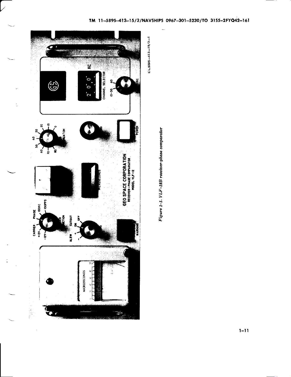
VLF-12Breeeiver-phasecomparator
Typical
illustrating
Typical
VLF-128
VLF-128
Functional
Simplif ied
Response
Detailed
Phase
Detoiled
Sampling
Schematic,
VLF-128
Schematic,
Characteristic
Schernatic,
Schematic,
Schematic,
Schematic,
Schematic,
Schematic, four
Schematic,
Schematic,
Schematic,
Schematic,
Schematic, 1-kc
Schematic,
Schematic,
Schematic,
Schematic, output
Schematic,
Schematic,76.8
Schematic,
Schematic,
Coaxial cable repair
Multiconductor
Loading
RF amplifier
12.25-kc IF
Second mixer
45-kc
(part
Local
MOD-10
and
!'our flip-flops
One-shot and
S1'nthesizer
(part
S''nthesizer
(part
100-kc
Servo and agc
1-kc IF arnplifier
Servo
vlf-12B
rcceiver-phase
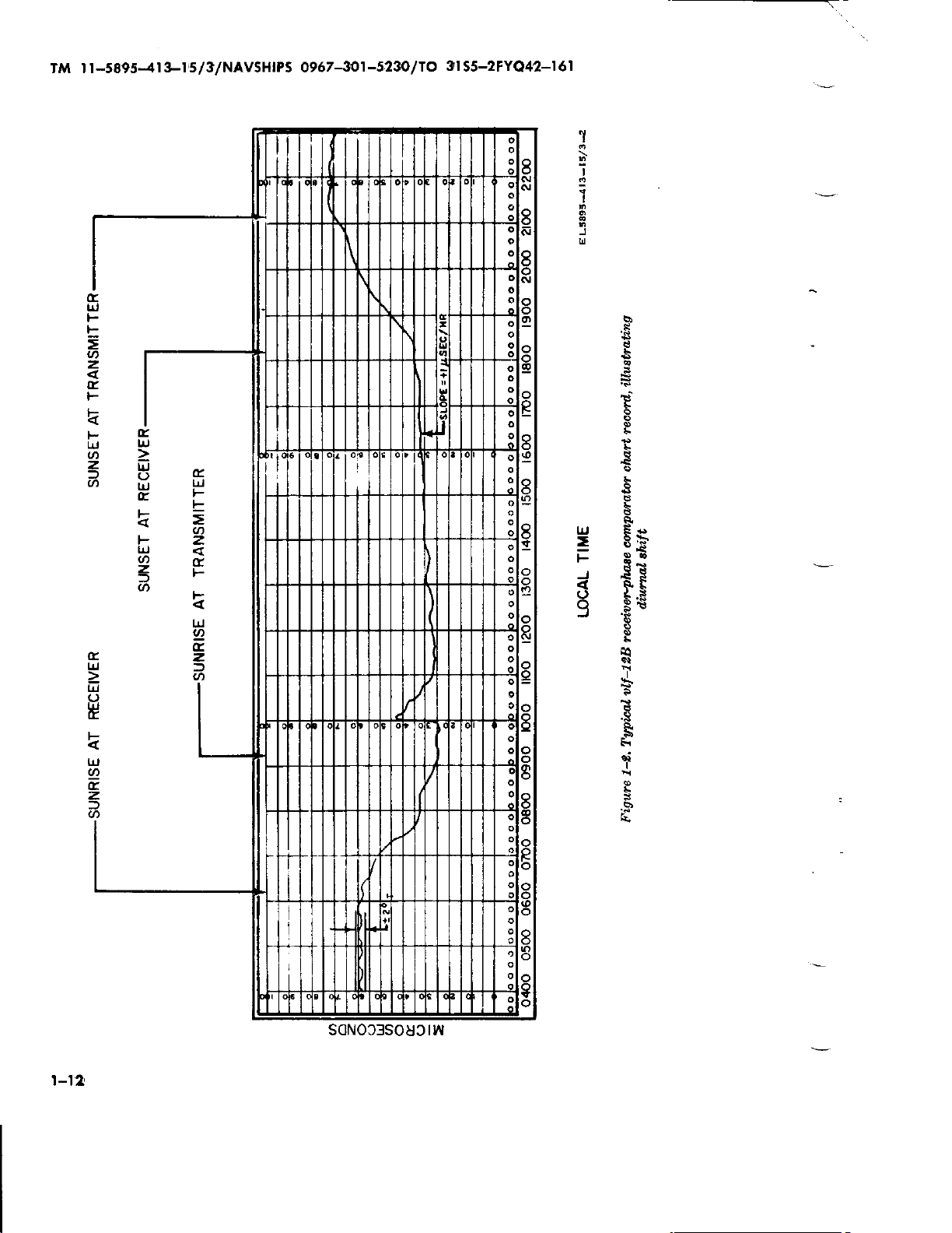
diurnal
packing
for export
receiver-phase
receiver-phase
diagram
diag"am,
curve
30-kv low pass
block
detector
diagTam, vlf-128
wavefonns
block
diag?am,
technique
vlf-128 receiver-phase
receiver-phase
RF
amplifier
curve
12.25-kc
second lnixel
three
flip-flops
local oscillator
MOD-10
flip-flops
one-shot
synthesizer
s]'nthesizer
servo and
lF amplifier
servo
cutout assembly,
audio amplifier
plus
and minus
buffer
100-kc arnplifier
to 100-kc converter
servo-motor
dc-to-dc
chart r€corder
and agc amplifier
to 11,250-kc
No. 200160)
oscillator assembly,
counter assembly,
(part
A23
phase
No. 200171)
phase
No. 200168)
arnplifier and
cutout
convert€r
cable repair
and firct hixer
assembly,
three flip-flops
No. 200022)
assembly,
reset assembly,
detector
det€ctor
--
phase
assembly,
a$sembly, A17
shift
comparator
shipment
compalator,
comparator,
of basic
vlf-128
vlf-12B
receivet-phase
filter
mechanical
phase
of
of
IF
counter assembly,
and rcset assembly,
agc
detectors
comparatol,
and first
crystal filter FL1
and agc
phase
phase
amplifier assembly,
assembly,
gates
and
and
VCO assembly,
assembly,
detector
detector
phase
det€ctors assembly, A15
assembly,
assembly,
1z-volt
assernbly, A25
phase
and
driver
assembly,
-------
assembly, A1A1
assembly, A2
(part
A4
and
(part
A6
A7, A8, A,21, A22,
----
(pa*
A9
A10
(slow-loop)
(fast-loop)
phase
shifter
detectors
assembly, A15
(part
A16
(part
receiver-phase
servo
comparator
mixer assembly,
A4
Ag __
A17
power
assembly, A24
No, 200151)
gates
No. 200163)
No. 200016)
(part
assembly,
assembly, A14
No. 2001?7)
ITTUSTRATIONS
OF
chart rccord,
panel
front
panel
rear
receiver-phase
comparator
compatator
top view
A1
assembly, Ab
A6
A7, A3, AZt,
-
A10
(slowloop)
(fast-loop)
A16
A19
supply assembly,
assembly,
assembly,
shifter assembly,
A18
(part
(part
assembly, A5
No. 200180)
No. 200139)
No. 20015?)
assernbly,
A12
A13
(part
(part
No. 200433)
No. 200142)
comparator
A2
A22, and AZI
A12
A13
A20
A14
---
No. 200154)
---_----
Plge
1-11
7-72
2-A
3-18
3-19
3-20
3-2t
.3-24
q-25
3\27
3-29
3-30
3-31
3-34
3-35
3-36
3-38
3-39
3-40
3-41
342
3-43
344
3-45
3-46
347
3-48
3-49
3-60
4-2r
4-22
4-23
6-2
54
5-5
F4
6-7
5-€
5-9
5-10
5-11
5-t2
5-13
5-14
5-16
llt
rM l t-5895-{r
}|'5/3/NAVSHIPS
O967-3()1-523Olt
3t
O
55-2FYO42-I6I
5-15
Servo-motor
5-16 Audio
5-17
5-18
5-19
5-20
5-21
5-22
Plus and
(part
?6.8-kc to 100-kc converter
Output buffer
Servo
Thumbv/heel
VLF-12B
driver assembly,
amplifier
minus 12-volt
200124)
No.
assembly,
switch
receiver-phase
tlST OF
assembly, A19
power
assembly,
assembly, A25
(part
A27
assembly,
No. 330034)
comparator,
A18
(part
supply
(pa!t
A28
IttUSTRAI
(part
No.
assembly, A20
A24
No. 200165)
(p-art
No.
200136)
(part
No.
bottom
200174)
IONS-Continued
200394)
No.
3301011)
riew
PlsE
5-16
5-L7
5-18
5-19
5-20
5-2t
6-23
TM I I
-5895-4r
ts-t 5/3/NAV5H
IPS @57
-3Ot
-5230
/
3l
lO
S5-2FYO42-I 6
|
CHAPTER
INTRODUCIION
Section
I-1. Scope
This manual contains
maintenance
and
Phase
called the vlf-12B receiver-phase
or simply
ponent
Digital Message
42(V)L
AN/FYQ-42
automatic d,igital network
manual is
1 contains
characteristics;
procedures
tions;
operation; chapter 4
maintaining
and chapter 5 explains location of illustrations
which support this
l-2.
Publ;icatiotu.
Comparatoi
vlf-128), which
the
of
Station
Switching Centers
throush
(V)
T1, which are
divided
Eeneral
chapter 2 contains installation
and complete operating
chapter 3 describes
and overhauling the equipment;
lndexes of Equipmeni Publicotions
u,. Neu; E tl,,itions, Changes, or Additiona|
Determine whether there are
operating
procedures
C.Vr364/G
Timing Units
AN/FYQ-4Z(V)12 and
(AUTODIN).
into five chapters. Chapter
information and technica:l
the
provides
equipment.
any new editions, changes, or additional
formation
pertaining
to
your
referring to DA Pam
NAVSANDA Pub
Index
(Air
latest
whether
Orders
I
Report
witl
and Requirement Table T. O. 0-1-01N
Force).
b. Motlification
edi.tion of DA Pam
there are
(MWO's)
Forms ond Records
-3.
a. Repor-t
unsatisfactory
procedures
of Unsatisfactory E
pertaining
in TM
(Navy),
2002
Work
Orders. Refer to the
310-7 to determine
any Modification Work
equipment in
3&750
instructions
for Receiver-
(hereinafter
comparator,
is a major com-
for Automatic
AN/FYQ-
part
principles
instructions for
equipment
310-4
or Numerical
to the equipment.
(Army),
of the
This
instruc-
in-
(Army),
quipment.
accordance
NW
I
l.
GENERAL
00-35-546
Force).
b. Report of
Deficiencies, Fill out
(Report
6
ciencies)
NAVSUP Pub 378
(Air
Force).
DiscrepancE
c.
out and forward
(DISREP) (SF
poit
55-38
or AFM
d,. Report of Maintenance. Records
ports
must
of
be
in TM
Subject: Planned Maintenance System
back Report
Force).
e. Report
ments.
mendations
individual
(Navy),
of Packaging
prescribed
as
in Shi,pment
Discrepancy in Shipment
(Army),
75-34
preventive
of
made in
38-750
Report of errors, omissions,
NAVSUP
(Air
accordance
(Army),
(Navy),
of Equipment
for improving this
is
user
encouraged.
TO-00-35D-54
or
Packaging
and forward
and
in AR 700-58
(Navy),
361) as
prescribed
Pub 459
Force).
maintenance
with
OPNAV
or AFM 66-1
Mantals
and
Handling
or
manual by the
Repofts should
be submitted on DA Form 2028
by
mended
forwarded
Army
Changes
to Commanding General, U. S.
Electronics Command,
ME-NMP-AD
07703
10-67)
forwarded
System Command, ATTN: 0451C, Washington
D.
22
ficiency
er, Oklahoma
OCNDT
73145
(Army);
(Formenly
to: Commander,
C. 20360
(Technical
Report) and forwarded to: Command-
(B-F),
(Air
Force).
to DA Publications)
ATTN: AMSEI-
Fort Monmouth,
NAVSHIPS 5600/2
NAVSHIPS
Naval Electronics
(Navy);
Order System Publications
Air Materiel Area,
City
Tinker Air Force
AFTO Form
or
(Air
Hand.ling
Form
DD
Defi-
(Army),
AFR 71-4
Report. Fill
Re-
in AR
(NavY),
re-
and
and repairs
procedures
Form
4700,
Feed-
(Air
Improrte-
and recom-
(Recom-
and
New
Jersey
(REV
4914) and
De.
ATTN:
Base,
Ok.
t-t
Tll t I
-5895-4
I 3-l
s/S/NAvSHl
PS
09
67
-3or
-s23o
ltO
3I
55-2FYO42-I
6I
I
Mojor
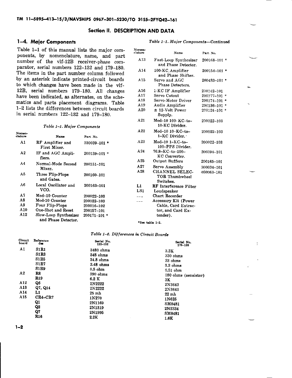
-4.
Table
1-1
ponents,
number
parator,
The items
by
an
asterisk
to which
12B,
have
matics
1-2
in
cl6tuE
serial
been indicated,
and
lists
serial
A1
A2
A4
.4.5
A6
A7
A8
Ag
A10
Al2
Components
of this manual
by nomenclature,
of the
serial
in
changes have
the
num,bers
RF
First
IF and AcC
fiers.
Normal-Mode
Mixe!.
Three Flip-Ftops
and
focal
vco.
Mod-10
Mod-10
Four
One-Shot
Slow-Loop
and Phase
vlf-l2B receiver-phase
numhrs
part
the
indicate
numbers
parts
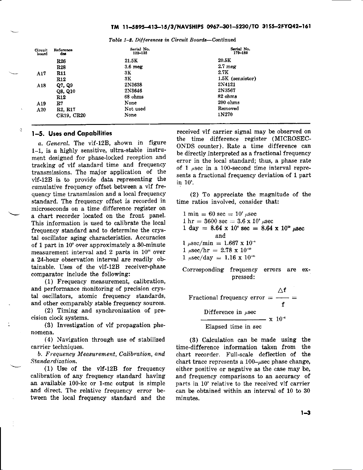
differences
Table
Amplifier
Mixer.
number
printed-circuit
been made
179-180.
as alternates,
pla.ement
between circuit boards
722-Lg2
1-1, Maior
N,m
and 330039-101
Ampli-
Second
Gates,
Oscillator
and
Counter
Count€r
Flip-Flop8
and
Reset
Synthesizer
Detector.
Seclion
lists
the
name,
12?-132
and 179-180.
column followed
All
diagrams. Table
and 179-180.
Cotnponetuta
Psrr
lilo.
200139-101
200151-101
200160-101
200163-101
2O\OZZ-|OT
2OOOZZ-7O}
200016-102
ZO}L'7-LOL
2001?1-101
ll. DESCRIPTION
major
in
on the sche-
and
boards
the vlf-
changes
.
,i
*
com-
part
com-
AND
Table 1-1, Majot
A13
414
A15
A16
A1?
A18
A19
A20
.{21
422
A23
424
425
421
A28
L1
T]
?6.8-Itc-to-100-
Output Buffers
Servo Assembly
cHANNELSELEC-
RF Int€rfelence
Chart
Accessory
DAIA
Cortupotuents-Co[finued
Nme
Fast-Loop
and Phase Det€ctor.
100-KC.
and Phase Shift€r.
Servo
Phase
1-KC IF
Servo
Servo-Motor
Audio
I
lz-Volt Power
Supply.
Mod-10
10-KC
Synthesizer
Amplifier
and AGC
Detectors.
Amplifier
Cutout
Driver
Amplifier
10G
KC-to- 200022-log
Divider.
Mod-1010-KC-to-
1-I(C
Divider.
Mod-10
Loudspeaker
l-[C-to-
100-PPS
KC
Converter.
TOR
Thumbwheel
Switches.
Becorder
Cable,
Card Extrac-
tor,
and Card Ex-
t€nder).
Divider.
Kit
Fitter
(Power
Psrt
No.
2001G8-101
200154-101
200433-101
200142-70L
2001?7-101
20017
4-L0t
200136-101
240724-101
2OOO22-1O\
2OOO22-|O3
200394-101
200165-101
300034-101
460063-101
+
*
+
*
*
+
*
Circuit
A2
Al3
415
1-2
A1
At2
AL4
s18l
slRil
s1B6
S1R7
s1n9
R8
Rl9
Q6
Q7,
QlA
L1
cR4-CR7
Q1
q2
Q?
Rl6
Table
1-2. Di,fferenooe
S€dal No.
122-L32
3480
ohms
348
ohms
34.8
ohme
3,48
ohns
0,5
ohm
390 ohms
6.2
K
2N2222
25
mh
1N270
2N1169
2N1319
2N1996
2.2K
in
Circuit Boardl
Sed.l No.
170-180
ii,3K
330 ohms
33
ohms
3.3
ohms
0.51 ohm
180 ohms
3K
2N3643
2N3643
22 ri\
1N625
sM8481
2N2334
sM8481
1.6K
(sensistor)
I I-5895-.{I&I6/3/NAVSHIPS
Tl
O967-{1-5t3o
O 3155-2FYQ42-I6I
lt
To,bl.e 1-2.
Cilcuit
At?
A18
A19
A20
I
-5.
a.
1-1, is a highly
ment
tracking
transmissions.
vlf-128 is to
cumulative frequency
quency
standard. The
microseconds on
a chart recorder
This information
frequency standard and to determine
d6
R26
R28
811
R12
Q7, Q9
Q8, Q1O
R12
R7
R2,817
cR20
cR19,
Copobilities
ond
Uses
GeneNLL
designed
The vlf-12B,
for
of vlf
standard time
sensitive,
The
provide
time transmission
frequency offset
a
located on the
is used to calibrate
shown
ultra-stable
phase-locked
major
application
representing
data
offset between
and
time difference
tal oscillator aging characteristics.
part
of 1
measurement
a 24-hour observation
tainable. Uses of the vlf-12B
comparator include the following:
and
in 10" over approximately
interval and 2
parts
interval
(1)
Frequency measurement, calibration,
performance
monitoring of
Dillercncea in
No,
S€ri,l
tz2-132
21.5K
3,6 meg
3K
3K
2N3638
2N3646
68 ohms
None
Not used
None
in
reception
frequency
and
vlf fre-
a
a local
frequency
is recorded
register
front
the local
the crys-
Accuracies
a
B0-minute
in 10" over
readily
are
receiver-phase
precision
figure
instru-
and
of the
the
panel.
ob-
crys-
tal oscillators, atomic frequency standards,
and other
cision
nomena,
carrier
b. Frequency M eosurement,
Standnrdizattion.
calibration
comparably
(2)
Timing and synchronization
clock systems.
(3)
Investigation
(4)
Navigation through
techniques.
(1)
Us€ of the vlf-lZB for frequency
of any frequency standard having:
an available 100-kc
and direct.
tween
The relative
the local frequency
stable frequency
of
or
propagation phe-
vlf
use
Cakbratinn,
l-mc
output
frequency error
standard and the
sources.
pre-
of
of stabilized
atd,
is
simple
be-
Circuit
Boar.ls-Continued
received
vlf carrier
Hrl
20.6K
2,7 tueg
2.1K
(sensistor)
1.5K
2N4L27
2N3567
82
ohm8
200
ohms
Removed
1N270
No.
1?9-rE0
signal
may be observed on
the time difference register
ONDS counter). Rate a
be directly interpreted as a
error in
1 psec
of
sents a fractional frequency deviation of 1
local standard; thus, a
the
in a 1O0-second lime
in 10".
(2)
To
appreciate
in
time ratios involved,
on
t hr
1
I
1 psec/hr : 2.78
L psec/
Corresponding
:
1 min
:
day
=
/,sec/min
60 sss
3600 sec
day
:
:
8.64 x 10'sec
and
:
1.66? x l0-"
:
1.16 x 10-"
frequmcy ernors ar€
pressed:
Fractional frequency error
Difference in
time difference can
fractional irequency
interval repre-
the magaitude of the
consider
10'Asec
x 10'ssec
3.6
that:
:
8.64 x 10"
x 10-'"
=
psec
x 10-'
Elapsed bime in sec
(3)
Calculotion can
time-difference
information taken from
chart recorder. Full-scale deflection of
chart
either
and frequency comparisons to an accuracy
parts
can be obtained w,ithin an interval of 10 to 30
minutes.
represents
tra,ce
positive
in
10'
a
or negative as the
relative
to bhe
made
be
100-psec
received
phase
(MICROSEC-
phase
rate
part
l6ec
ex-
Af
:
f
-
using
case may be,
vlf carrier
the
the
the
change,
of
IJ
(4)
In reading the chart
accumulated
the recorder displays a
that
mental range
phase
obtained,
full
parsion
over an elapsed time
excursions of the
phase
however,
with
error, it
100 psec. The total change
of
keeping
by
recorder and by
the digital
ter. A discontinuity in the
the flyback
recording
because the trace
posite
aging
be visualized by converting the basic data to
a
characteristics of the
daily
(5)
makes
of
local
a
periods.
tion
a
crystal oscillator
aging rate. That
for example, higher
rate. During
is changing rapidly,
several
(6)
four months
placed
be
turned off; the entire
be repeated
(7)
recorder,
indicates
the chart
function
time
is frequency,
is frequency
is
chairge in rate
determined
short
monitoring
(8)
tion
of observation
chart
trace
or
the
local
oscillator
periods
For
crystal
able. An
procedure
ment
point
on the continuous-rotation
potentiometer,
will
continue
edge of the chart.
"frequency
Proper use of the vlf-128 record
possible
it
precision
error"
to determine the
oscillator between calibra-
After an initial run-in
has
a
its
is,
each d,ay at a uniform
the run-in
period
but can be
days.
The
run-in
period
of continuous
in operation
each time the
In
using the vlf-l2B
it
is important
change in
indicates this
of time.
(.rate)
by continuous monitoring
Precision of
width
perriod
of one day,
oscillator
example of measurement
the oscillator should never
phase;
change in
Change
so the slope
error.
error. These
periods
measurement
noise, which
and the
between
predictable
is
a typical high-quality
can
be assumed
given
is
below.
records of the
must
maximum incre-
time-difference regis-
recognized
be
interval
record of
a
can be
the
com-
record occurs at
trut no data
from the
Frequency drift
oscillator can best
plot.
is lost
op-
performance
period,
relatively constant
frequency becomes,
the aging rate
projected
consists of one to
operation.
run-in
oscillator is restafted.
to know that the
period
with
its
for
Once
must
chart
pen
the movement of
phase
phase
in
of the
Change in the slope
errors
per
pen
can
as a
unit
line
or by
at regular intervals.
is a func-
is related to
period
observations, if
of
observation
between
to be
and adjust-
the
periods.
predict-
(9)
Assume that observations
once a day. On the
quency
in
day
the
ter
observations
one
from nominal
f.
or
The frequency for that
f : f"
error.
ard
markings in incrernents of 1
the knob 5 divisions
The next day's observation
curacy of this adjustment
slope of the
gained
and,
be
out
between' observations
sirable
compensated
quency
if
to
oscillator may
standard was
(t')
chart
of
+
there
50
is an indicated
recorder and
psec. If the elapsed
was
the eror
day),
(f")
50 x 10' sec erroill
f"x
=
(10)
will
(11)
if
adjusted
making
(12)
10' sec elapsed timo
f",
+
assuming
Ordinarily,
have
an adjustment
line.
After the
each day
necessary, the
with
a new ob,servation, or
In
some applications
that the oscilrlator be
rather than set exactly on
whenever an adjustment is
experience indicates that the oscillator tends
(age)
drift
toward a higher frequency, the
be adjusted so that it starts off
with a negative frequency
The overcompensation
be
in the maximum
adj ustment
oscillator
(13)
used
for frequency
pends
global
in
be
instructed
mitter
ceiving
ary stations
will be required
within specified
Selection of
upon many
network operation
to monitor
that can be reliably
sites.
Selection of one
is
advisable so that no receiving
made
are
firsb day
not adjusted.
(t')
time-difference
10' smonds
in the frequency
ll-as:
local fre-
the
The second
error on
time
between
time
(slightly
standard
regis-
over
:f"x5x10"
24-hour
no appleciable
local
frequency
the
knob with
pp
to correct
run-in
the
indicates
the
by
period,
will be vidually
frequency standard
considerable
can be increased.
confidence
period
10'".
frequency.
the
lvas
aging
stand-
dial
Adjust
the ac-
resulting
time
the
constant,
may
with-
period
it may be de-
slightly over-
fre-
made. Thus,
deviation
technique will
time interval before another
maintain
to
tolerances.
the vlf
correlation
factors.
station
purposes
Groups
will undoubtedly
particulat
some
tracked
more
or
error.
result
to be
involved
trans-
at all
second-
the
de-
re-
l-{
TM I t-5E95-41i3-15/3/NAVSHIPS
0967-30l-5230
lto
3,I
S5-2FYQ42-I6I
site is wholly dependent
mitter. The
stations are listed in
upon a single trans-
t-I.
c.
Clock Synchronization It is
use
the vlf transmissions directly for time-of-
day
information
example,
second intervals.
tion
slow
mitted
The
in
the neighborhood
cause
700. This
radiating
Nevertheless,
able
slope
and
clock
d., Itwestigation
nomem,o,.
phenomena
agencies,
ies
of
transmits timing
envelope of the keyed
rise time that the
time
NBA
transmitted sigxral
of
transmitting
a
is required
efficiency at the low frequency.
synchronization
of
the
are being
settings.
(1)
Investigations
here
the diurnal
vlf-reflecting
ies
of
the effects of magnetic
ospheric
reception
sions is true
agation
ness,
more
sunset
(36
determined
tween
by
the seasonal
twilight;
longitude,
disturbances;
of the various
(2)
The
path
with
daytime
stable. During
there is a shift
psec
at 18 kc).
by the
the transmitter
if
the shift will
purposes.
Station
pulses
Unfortunately,
carrier
beginning of the trans-
pulse
is difficult to recognize.
has
of 15 milliseconds be-
antenna
Q
to achieve
various
modulation
schemes to obtain reli-
points
on the leading
have been
used successfully
of VLF Propagation
of vlf
are being
and abroad. These include
D layer
ultra
for cases where
is
either
there is
carried out
change
of altitude in the
of
the atmosphere; stud-
and sudden ion-
and
comparisons of
vlf
transmissions.
stability of vlf
the entire
in daylight
transmissions being
periods
in
period
The
difference
and
variations
of sunrise or
phase
of about 200o
of the shift is
in longitude
the receiver,
in
the length
a difference
occur over.
or
at
the
a r,ise time
propagation
paragraph
possible
NBA, for
precise
modula-
has
such
of roughly
reasonable
developed,
to achieve
Phe-
by various
stud-
transmis-
prop-
in
dark-
the
be-
and
of
of
approxi-
T5o
in
mately
and sunset)
posite
to
only real
sonal valiation
night
little
1-
predicted
be
a
accomplished
the shifts
period).
effect on
transmission
ionospheric
phase
with
effects
be identified
covery,
removed
parison.
'
tration
disturbance
rise
and sunset
mitter
er. An
e. Nattigation.
used for
LORAN
received.
quency
chart
for
radial
tions
dead-reekoning
mile
conditions.
I-6.
a. VLF stations which
of conbrolled
table
hours.
5
These diurnal shifts
are equal in magnitude and
in
direcbion, and extremely
changes are due to the ordinary
in the length of the day and
and the duration
local
experience, the diurnal shifts can
and fretluency calibration can be
even during the shifts
cancel for a 24-hour observation
(3)
Lagnetic
stolms
nighttime
is virtually
disturbances
shifts as large
recovery
cannot
and can
taking
predicted,
be
by
the sharp rise
then either be
analltically
(4)
A typical
of diurnal
is
about
30' longitude
S.I.D. is shown
vlf-l2B
shift and sudden
shown in figur.e
effects
VLF
navigation
C or
OMEGA
For
this application
standand,
record€r,
velocity
are required.
two vlf-12B's,
and some forrn
with respect
It has
transmission, but daytime
about
from the frequency
purposes
twilight.
of
produce
unaffected. Sudden
(S.I.D.)
as 100o in 5 minutes,
an
of course, but can
chart record illus-
shown
are
west of
occurring
transmissions
in areas
transmissions
of compensation
been reported
navigational
or
Iess can
VLF Time
be realized
Service
Stotions
during
transmit on a basis
carrier frequencies are listed in
1-3.
(sunrise
regular.
With
(of
course,
turbulent
a
produce
can
hour. The
and slow re-
discounted or
1-2. The
for
at 10 o'clock.
preeision
a
a dual-channel
to the
accuracy
S.I.D.
ionospheric
a trans-
the receiv-
can be
where
are not
vlf sta-
of 1
all daylight
op-
The
sea-
a
com-
sun-
fire-
that
OMEGA
GBN,
FUB
Table 1-3. VLF
70.2
16.0
16.8
fi,rna Seruice
Various; Clobal
Rugby, England
Paris, Fralrce
Statimu
Net
U.S. Navy
RNOUK
IJ
rr I t
-5895-413-I5/3/NAVSHIPS
NAA
NPG/NKL
GQD
GBZ
wwvL
NSS
NBA
NPM
wwvB
The U.S.
b.
subject
are
quencies
1965.
listed
AII stations
UT2 Time
c. The
and the United
time and
in the
tions
ters stabilized
pulses
Time
lized carrier
Navy
change
to
those
are
except
Base: WWVB
Time Service
Kingdom
frequency
coordination
Atomicron
by
synchronized
are
frequency,
A-1 to minimize the
frequency
and UTZ.
constant throughout
ified as follows:
nominal
the
s is the
most
fractional
mined,
Observatory
The value for
10-".
d.
broadcast
The
F:
frequency
fractional
nearly
equal
offset
in
advance,
The value of
each 15
offset
to the
for any
the U.S.
and
both 1964 and
0967-.gJ1-523ol10
Tabte 1-3.
17.8
18.6
19.0
19.6
20.0
21.4
24.0
26.7
60.0
frequency
without
in use
assignments
notice.
as
WWVB
A.1
uses
Stations
vlf links.
by
are
plan
of
coordinated
All the
have transmit-
(cesium)
with
which
difference
one
any
(1
F"
of
is
between
transmitted
year,
5),
+
transmitter
the
which
gives
rate of
year
is
iointly
by the Royal
Naval Observatory.
1965
the fractional
minutes
in International
Time Serrice
VLF
fre-
The
of January
operate
Base.
Time
U.S.
the
sta-
clocks.
the stabi-
offset
and
where
was
from
A.1
remains
is spec-
F, is
and
rate
a
UT2.
Greenwich
The
deter-
-150
offset
3rl
Cutler,
Jim Creek,
Anthorn,
Liverpool, U.
Ft. Collins,
-q.nnapolis,
Balboa, Canal
Laulualei,
Boulder, Colorado
Morse Code,
from the
on
the carrier
pulses
at all
in
milliseconds on the
changes
FYQ42-I
55-2
Stotiorrs-Continued
Maine
Washington
Scotland
K.
Colorado
Maryland
Zone
Hawaii
received carrier
e. Seconds
depart too
the transmitting
are
Greent"ich Obselvatory
Observatory.
changes
l.
will
U. S.
Bulletins A and
transmitted
UTO and A.1.
and
Apparent and
(the
"equation
the equinoxes",
the American
nac,
x
is
Technicol Chorocteristics
l-7.
Table l-4 lists
for
the
vlf-128.
6I
Navy
U.S.
U.S. Naqy
NATO
KNOUK
National
U.S.
U.S.
U.S.
National
A.l can readily
so
pulses
frequency.
are locked
far from
Whenever
Bureau
Standards
Navy
Navy
Navy
Bureau
Standarde
frequency'
UT2,
stations are
of a
first
jointly
determined
and the
No more than
be necessary
ever
one or
Naval Observatory
give
B
frequencies
final
obtain UTz,
to
The differences
Mean
of time" and
respectively)
Ephemeris and
Solar
and
the "equation
are tabulated
Nautical
the technical
of
of
determined
be
in
phase
the
the
with
seconds
clocks
shifted
trvo
The
Royal
Naval
such
year.
month.
by the
U. S.
in one
Time Signal
corrections
UTf,
between
Sidereal
characteristics
Times
Alma'
50
to
of
in
rrequency Coverage
IJ
tr .tur!
Table 1-1,.
Techtuical Characteri.stiaa
VLF channel tracking
ments for all
spectrum betwe€n
is entirely
detent, Channel
without the use of
adjustment of
any other frequency-determining
A 60-kc channel,
front-panel switrh, is also
required for optimum operation,
possible
by thumbu'heel
selection
the local oscillator,
selectable
Oher8ctet{lnica
provided
is
channels
10 kc and
is
plug-in
in
in the
30 kc. Channel
sivitches
positive
filters and
with
and accurate
rf selectivity,
circuits.
by m€ans of
provided.
No tuning
100-cps incre-
frequency
selection
position
without further
or
a sepalate
is
rfrt I I
-5895-4lrlls/3/NAVSHIPS
@67-@1-5230
3lS5-2FYO42-I6t
llo
Randlvidths
Beceiver Sensitivity
Signal Level Operating Range
.\utomatic Gain
Response to Undersirable Sigaals
Control
(AGC)
Adjacent Channel
Rejection
Spurious Responses
Image
Rejection
Desensitization
Tabte 1-1.
Technical
Charactedsiics-Continued
Ch.ruteriltica
Bandwidth
cations
handling
RF module
image rejection: 8 to 30 kc
restriction
within
capability
pass
the
is supplied
receiver to ensure
of each
(single
band
l'irst inter:mediate frequency
200 cps
Second intermediate
(nominal)
50
cps
Phase-tracking servo
frequency
bandwidth:
at appropriate
the desired siShal-
function described:
filter) for 60-db
(12.25
kc)
(1
pass
kc)
0.006 cps
(nominal)
input tevel of 0.01
An
and a sigaal-to-noise
measured in a 1-kc bandwidth)
phase
tracking
0.006 cps.
The noise figure of the
internal receiver noise
and
recorder
more than
caused by internal receiver noise,
receiver is
coherent
is 0.006
The total operating range of
cps.
u'ith a nominal
o! the time difference
microsecond
0.3
tracking
generator
microvolt across
ratio of
-50
servo bandwidth
receiver
will result in accurate
will not cause
register
jitt€r.
a 0.ol-microvolt
and the nominal
signal level
This range is accomplished by the
step attenuat r having
steps coupled lvith
gain
contml
A stable
over a
(agc).
agc circuit
40-db
range
than 0.5 microsecond of
the agc sigral
is
ture detector designed
phase
between the receiyed
standard.
The follorving characteristics are
a normal input level of 1 microvolt
signal, and assuming
a range of 80
a minimum of 40 db
assures reliable
of input carrier
phase
shift. The
accomplished
to
by the
provide
station and
that all receiver controls
is Iess than 20 db,
50
(Gaussian
db
to display
The limit on
when
exists
sigral from a
servo bandwidth
is 120 db'
a manual
use of
db in 10-db
of automatic
phase
level with less
detection of
use of a
regardless of
agc,
the local
given
assuming
for the desired
optimized:
.A. coherent siglal 100 cps
and 30 db larger
affect the
in amplitude will not adversely
phase
tracking
Similarly, a signal 200 cps or
signal and
phase
the
The
spectral
vlf-128
the
responses, 100 cps or more from
hy
the thumbwheel switches, from limiting the
cent channel rejection charact€ristics specified.
Image rejection is 60 db or
frequencies without the use of
larger in amplitude
60 db
tracking
purity
are sufficient
ftom the desired sigaal
of the desired sigrral.
more from the desired
urill not affect
of the desired sigTlal.
mixing frequencies within
of the
provide
to
greater
any undeeired
the
channel
at
plug-in
all selected
filters and
without repositioning the local oscillator.
With
the receiver
and undesired sigral
frequency from the desired
larger in amplitude, will not lowe! t}re
receiver to the desired sigaal by mole thatr 3 db.
properly
located 200
to a desired channel,
tuned
channel,
or more in
cps
and 60 db
gain
Io-
pass
band:
band:
ohms
noise
of
the chart
iitter,
the
tracking
quadra-
are
selected
adja-
of the
t-7
rM r l
-5895-41
3-|5/3/NAVSH|PS 0967-30l-5234/10
l'eature
Intermodulation and Harmonic Dist rtion
Response
Fr.equency
Coherent Signal lladiation
Receiver Inputs
Receiver
Synthesizer
Outputs
IJ
3lS5-2FYO42-l6r
Tabte 1-1. T echnical C haracte?1istics-Continued
-{11 second- and third-order
and undesired channels are 60 db lower
than the input signal.
Tbe
choice of the first intermediate frequency and
the desigr of the frequency synthesizer
local-oscillator injection frequency that is locked in
100-cps increments
rnal
100-cps
24.45 kc. The frequency offset
oscillator signals radiated by the antenna from inter-
fering $'ith other
discrete frequencies are not
normal vlf
selecting
and
channel frequencies. The frequency-
srvitches set the desired 100-cps
provide
station frequency.
frequency and then
the synthesizer
second,
phase-coherent
The
antenna input
(0.001
microvolt).
Trvo separate
are supplied with
panel.
rear
A 100-kc frequency standard input is
means
of a BNC
nominal 10K input
betrr-een 0.5 volt
The following
panel
BNC connectors:
Amplified
quency
same
100-kc square
and
phise
carrier and is
10-kc square
carrier
1-kc
and is a nominal
square wave
carrier and is
100-cps square wave
carrier and is
DC
output voltage
to the
relative
standard
1-ma
and
external
reai chassis
calibration to obtain a full-scale
that reptesents
panel
A rear
phase
difference
ternal
The
panel:
or int€rnal
following
built-in
-{
and a chart
calibration
Built-in
if. A
range
speaker for
front-panel
to shut off
but offset by 50 cps
incremcnt;
coherent
direct indication of the desired vlf
After
returned to an
phase
signal level
connector is Iess than
rf inputs, 50 ohms and 10K nominal,
BNC connectors mounted on
connector on the rear
accommodates a signal level
and 15 volts rms,
outputs are available on the rear
vlf
carder
200-cps
information
potentiometer
outputs are available
chart recorder with
speed of 1 inch
of the
band$'idth
wave that is coherent with the vlf
a nominal t volt
rvave that is
that is coherent with the vlf
nominal
a
nominal
a
that is accurately
phase
vlf
the
recorder or the intemal recordet.
100 microseconds
switch is
output voltage
recorder,
chalt
volume
tlle audio
Chara.teriotie
products
e.g,,24.25 kc,24.35 kc,
phase
phase-coherent
of the desired
in
amplitude
produce
from
prevents
any locai-
detector, since the
the
to the
incremert
being
switched to
another
original settilg,
is
shift
less than 0.5
present
at a 1-kc intermediat€
at the
dbm
-16?
provided
panel.
micro-
50-ohm
The
fre-
that carries the
as the
leceived sigral.
pp
across 50 ohms.
coherent with the vlf
pp
volt
1
1 volt
that is
1 volt
across 60 ohms.
pp
across 50 ohms,
coherent
pp
across 50 ohms.
with
the
proportional
difference between the local
carrier, for driving
adjustment
nominal
a
provides
chart deflection
provided
of
to connect the
change.
phase
to eiiher the ex-
on the front
inkleBs
pet
paper
is 100 microseconds,
aural monitoring
control
hour.
Full-scale
provides
stylus
of the 1-kc
adequate
signal completely
a
nor-
the
by
vlf
A
span
TM
r-58954lr3-r
I
5/3'INAVSH|PS 0967--30I-5230
3',tS5-2FYQ42-|
O
lt
6r
\*
Phase-Tracking
Servo
l\Ieter Display
Interrupt Warning
Time Difference Register
Calibration
Accuracy
llnvironment
Power
Requirements
T@ble 1-t,
Technical
Characteristics-Continued
provide
or t,o
ventional
An
electromechanical servo maintains a
shifted
reference sigral in a
relative
Servo
Phase-tracking
mum fractional frequency offset
Manual
panel,
servo
at approximately tw'ice the rate
sufficient audio
operating
to a select€d vlf carrier.
deadband is
servo slewing switch, located
advances or retards the
Char&tenisti6
environments.
0.1
=
error is less than 5
power
phase-null
nominal.
tsec,
phase-tracking
for use in
phase-
condition
Asec
(1 pp
on the front
experienced
at the maximum fractional frequency offset
given
a
leceiver
.{ front-panel rneter,
markings,
observe
receive!.
METER
independent
monitors signals that the
to determine the
The sigral or level
FUNCTION switch to allow
time
constant.
1trith
special calibrated
performance
operator must
status of the
is selected by the
individual and
monitodng of the following
signalB:
Belative carrier level
Phase
Positive
det€ctoi
gupply
error:
voltage
voltage
Negative supply voltage
Indication
quency
Indication
sizer signal
The front-panel indicator
inteuuption
standard input
manually
to normal
Another
carrier,
and will automatically turn off
carrier is
A front-panel
driven
by the servo, displays the relative time differ-
ence between
carrier,
seconds.
The
is
specified
The
calibration accuracy, relative to a received carrier,
better than a 1 x 101r on a 24-hour basis, over the
variation
The vlf-12B
+65"
to
ceiver
psec
receiver is
C at a relative humidity of 95%, Total re-
phase
over
tion encountered
The vlf-12B
95 to
130 volts rms, 48 t
of less
than 25 watts. All of the
are maintained
If a
recorder is supplied,
must be
128 may
source to
the ac
chosen to suit the line frequency.
power
proper
of
operation of 100-kc f!e-
standard input
proper
of
in the ac
has occurred. Only the
operation of
provides
power
100-cps synthe-
a u'arning if
or the local frequency-
indication
resettable; the vlf-128 returns automatically
operation when service is restored.
front-panel indicato|warns of any loss of
when the
returned.
MICROSECONDS
digiial
the local standard and the vlf
counter
is cumulative to 9999.9
countcr,
temperature range and input ac line-voltage
t lerance,
operates
shift from all causes
a temperature range of 0o C
desigred to withstand the shock and vibra-
operates from an ac
also be
enable automatic
should
properly
over a range of
is less than t
durirg normal shipping.
power
600 cps, at
over these
basic specifications
line-voltage variations.
ac
the s,'nchronous motor
connected to a
24-volt
operatiolr
fail.
to
50o C. The
source of
power
a
The vlf-
dc standby
in
the event
con-
at the maxi-
10').
or for
dial
is
micro-
-20o
1.0
level
C
I-9
Til t t
-5895-4
M 5/3/NAVSHIPS 09 67
-3ol -523)
TO 3l S5-2FYO4il-l 6I
I
l-8.
Physicol Description
o. The vlf-12B is designed to be
in
a slandar:d
than 7 inches high, and requires no
l9-inch rack
position
18 inches in depth behind the front
The net weight is
b, The unit is constructed of functional
modules arranged for ease of maintenance
approximately
mounted
not more
more
pounds.
45
than
panel.
and troubleshooting. Each module
quate
particular
a
for monitoring
operation. An extender card is
incircuit testing, and a card extractor
vided to allow easy removal of
cards.
test
points
to
module. All
without
isolate any trouble
points
interrupting normal
has ade-
are accessible
pmvided
printed-circuit
within
pro-
is
for
t-to
rM I t
-5895-4t3-r
5/3
/NAVSH|PS
@67-3O1-52i!O
I
e
E
3rS5-2FYO42-r6l
lto
g9
z
ar-
trt
d,,
od-
ts
*
&tr
8za
gli
o-*
vr;n
8!
3
t
!a
:r
s
i
9
6
t-t
r
TM I I-5895-.413-l
5/3/NAVSHIPS O967-3O1-523Olt
3l
S5-2FYO42-I6l
O
ts
a
!
F.
ul E-
- 8F
F
B:
r .!s
< *E
(.n
o
q
B{
9
t
'I
ts
B
I
ts
t-I2
s0NoSfsouc rw
ri t I
-5895-413-l'5/3/NAVSHIPS
0967--30l
-5230
3I55-2FYO42-I6I
llO
2-1. Generol
This
section
unpacking and
phase
comparator.
2-2.
Unpocking
Equipment
When
packed
is contained
figure 2-1.
during
below:
a. Transport
location.
b.
Cut
c. Remove
wooden box
pry
to
lids.
d, Open
the
carton
carton.
e. Open carton
proof
barrier
Remove inner carton. Open
l.
and
remove equipment.
Caution:
strum€nts when opening
cause
damogr
g.
Upon
containers,
shipped agree with
terior for any
as dents,
loose control knobs.
mediately.
contains
installing
for export shipment,
in a tlpical
To avoid damage
unpacking,
fold back
and
nails from top
with nail
moisture-proof barrier
inside
within the carton.
Never use sharp tools
to the equ,ipment.
removal of equipment
check
visible signs of damage, such
nricks,
detailed instructions
ond Checking
carefully
package
the wooden box, and
and second
to see
packing
or scratches,
Report any
INSTATLATION
the vlf-12B
lhe
package
to equipment
follow
to desired
metal straps.
and one
puller.
Do
moisture-vapor-
inner carton
cartons,
whether
list. Inspect ex-
and broken or
CHAPTER
Section
l. INSTAIIAIION
for
receiver-
vlf-12B
the
shown
as
the steps
operating
of
side
not attempt
covers
that
remove
or in-
as they may
from the
items
all
defects im-
2
AND
in
OPERATION
Tools
2-3.
lnstollotion
o. For vlf-12B's
intended for bench
is required
b. VLF-12B's
a standard
commodated
panel
be
clearance. Tools and
height. The depth
least 22 inches
at
Equipmenl
ond
supplied
mounting,
therefore
and
intended
l9-inch equipment
in a space adequate
install the equipment
following:
(1)
Screwdrivers,
no tools
for
of
to allow
hardware
in the
common
head,6and8inch
(2)
(3)
(4)
l/16
to l/4 inch
(5)
rack
used)
(6)
split
lockwashers
c. Ancillary
of small sockets
Set
power
-inch
l/
Assortment of
in
Countersink
drill
drill bits
32nds
bit
Nuts, bolts, and assorted
equipment
required
a long-wire, whi'p, or loop antenna; a
(normally
cord
two
50-ohm coaxial
length
antenna
receiver,
in
with BNC
table
and local frequency
A list of mating
2-1.
2-4. lnstollotion
a. If
the vlf-128
necessary
antenna
local standard
only to connect the
leadin, and the coaxial
supplied with receiver); and
cables of appropriate
connectors
connectors
Procedure
is
cabinet
to the desig:nated
Required
with
for
a cabinet
installation
no
are
required.
installation
be ac-
can
rack
for the
the rack
for
7-inch
should
connector
required
rack include
Phillips
and
(1/4-inch
(for
drive)
metal),
(depending
flat and
includes:
power
to conneot the
standard to the
is
mounted, it
power
cord, the
line from the
connectors
in
to
the
upon
given
is
IM
I
r
-5895-4
3-l
I
5/3/NAVSHIPS
0967
-*t
-523o
tO 31 55-2 FYQ42-I 6l
I
at the rear of t}re chassis.
na is
whip
50o input. It
coaxial
connect to the HI
used,
or loop antenna
is
not necessary to use
lead-in
with the long-wire ant€nna,
but use of a shielded
minimize
strong
local interference
If a long-wire anten-
Z input.
is used, connect
line, of some type,
is rrecom-
mended.
Tabb
Ohr..i!
50-ohm
Hi Z antenna
100-kc
10-kc
1-kc
0.1-kc
Local standard input
1-kc if.
Extcrnal
AC
art€nna
coherent
coherent
coherent
coherent
recorder
po\f,er
Notc 1: With RC-174/U cable use Gremar t]?e 6399.
RG-68/U cable use BNC typB UG-88/U.
With
With RG-62/U cable
Nota 2: Chassis connector
BNC type UG-1094/U
BNC
type
BNC type UG-1094/U
BNC type UG-1094/U
BNC type UG-1094/U
BNC type UG-1094/U
BNC tlTe UG-1094/U
BNC t,'pe UG-1094/U
BNC
type
Note 2
use BNC type-260/U.
is integral
part
b. For installation of a vlf-128
If a with
to the
mounting instructions supplied with the
drawer
slides, consult the
50-oh,m ticular rack used. With
able racks, it is necessary only
to bo
2-1. Liat ol
conn6to!
UG-1094/U
UG-L094/V
of rfi filter.
predrilled
necessary
the s'lides.
Mating
to drill
Connectorc
rack bars. With
special holes to accommodate
ll&tlns clnnlotor
Note 1
Note 1
Note 1
Note 1
1
Note
Note 1
Note 1
1
Not€
1
Note
MS 3106A 105I-36
equipped
equipment
par-
most commonly avail-
to bolt the
some racks
(C)
slides
it is
2-5.
Generql
This section
provides
information on all
erating controls, ind'icators, and
plus
instructions for operating the
Refer to
and to table 2-2
indicators,
2{. Preoperotionol
When the vlf-12B is to be
ice,
ried
a. Connect the
to the AC POWER
the
b, Plug the
a nominal 120
from 48
be used, conneot
D.C.
c. Connect an
propriate
figures 2-2 ar,d 2-3 for
for functions of the controls,
and connectors.
Procedure
put
into actual serv-
the following instructions should
out step by step.
three-conductor line cord
connector
panel.
rear
to 600 cps.
POWER
input,
into
cord
volts ac at any line
If standby
the
+24
connector on the rear
available antenna to the ap-
50o or HI Z, depending upon
outlet
an
dc
volt dc source to the
Section
connectors,
vlf-12B.
locations,
be car-
provided
providing
frequency
power
is to
panel,
ll.
OPERATION
op-
on
the impedance of the antenna
wire-Hl Z; Toop or
d.
Connect either
signal
(0.5
to 15
whip-50o).
the
volLs, rms) from a
standard frequency source
STD connector on
kcl100 kc selector switch,
and to the right of the connector,
propriate
e.
open
on
the chart
located on
Position
screwdriver
(The
snap button hole
recorder
knurled
l.
s.
db.
local
Loosen
the recorder
the rear
recorder stylus,
adjust, to the center
mechanical adj,ust
panel.)
thumbscrew.
Set AUDIO volume
Set DB ATTENUATION control to 80
the rear
reference frequency.
the knurled thumbscrew
panel
to discharge
paper;
then set
panel,
to the
with
is
plug
at the top center
Close
panel
control at
circuit
100-kc or 76.8-kc
to the
panel.
which
the record switch,
INT.
the
of the scale.
located
and
(long
local
LOCAL
the 76.8
Set
is
adjacent
to the ap-
the static
position.
mechanical
under a
of
tighten
midrange.
and
the
the
2-2
v
N.D.
METER
Metei
Chart
SERVO
INTERRUPT
and
MICROSECONDS
ference
DB .{TTENUATION
Switch
Recorder
Lat hing
FUNCTION
Selector
Switah
WARNING
Relay
Regist€r
Time
Selector
Lamp
Dif-
TrrA r r
895{ tts-t
-5
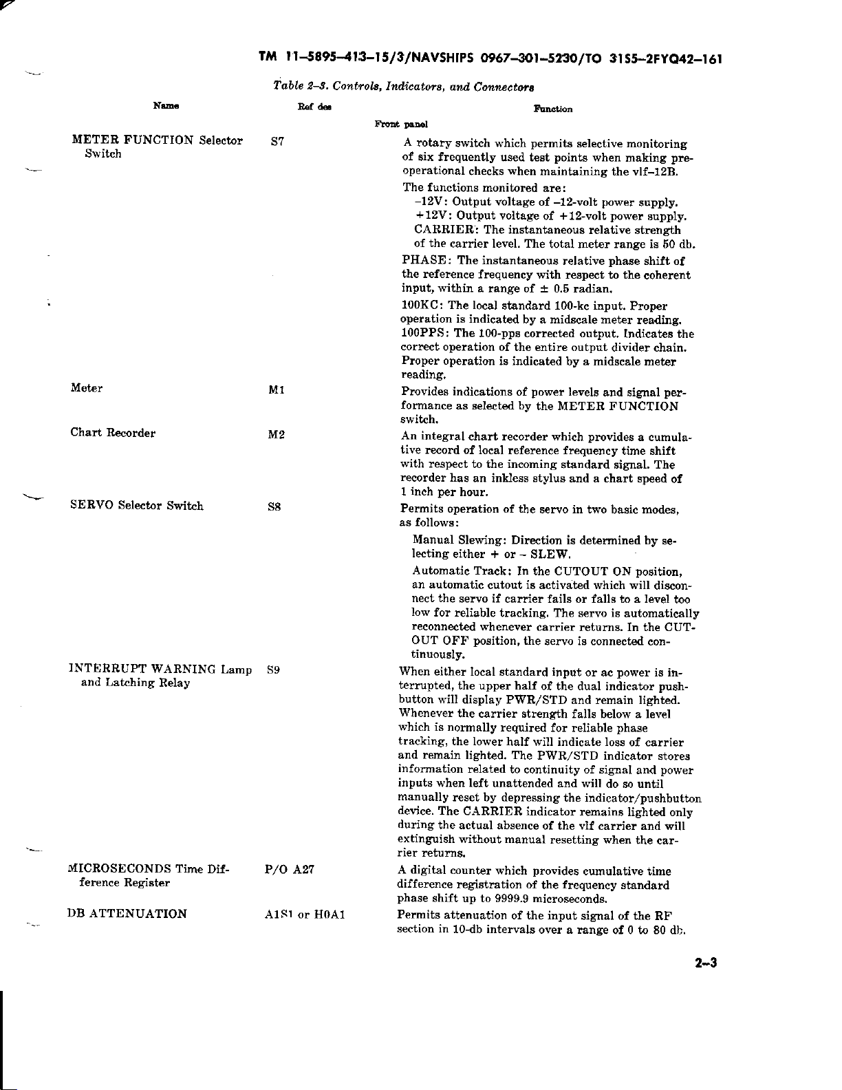
iable 2-s.
R€f d6.
M1
ttIz
s8
P/O 427
AlSl or H0A1
5/3/NAV5H
Controta, Indioatofi,
A
rotaiy
of
six frequently
operational
The functions
-12V:
+12V:
CARRIER,
of the
PHASE:
the reference
input, within
100KC:
operation
100PPS:
correct operation
Proper
reading.
Provides
formance
switch.
An integral
tive
record
with
respect
recorder
inch per
1
Pemits
as follows:
Manual
lecting
Autornatic
an automatic
nect the
low
for
reconnected
OUT
tinuously.
When
either
terrupted,
button
Whenever
which
is normally
tracking,
and remain
information
inputs
when left
manually
device.
during
extinglish
rier
retuma.
A digital
difference
phase
shift
Permits
section in
rps O967-3Ot
and,
Cotunectofa
switch which
used test
when
checks
monitored
Output voltage
Output voltage
trhlctlon
permits
I
-s23O
selective honitoring
points
maintaining
are:
of
-12-volt
of +12-volt
: The instantaneous
carrier level. The
The instantaneous
frequency
a
range of t 0.5 radian.
The tocal
is indicated
The
operation
indications
as selected by
standard 100-kc input.
100-pps corrected output.
of the entire output
is indicated
total meter range is 60 db.
relative
witi respect to the
by a midscale meter
by a midscale meter
power
of
levels
the METER FUNCTION
chart recorder which
of local reference ftequency
to the incoming
has
an inkless stylus
hour,
operation of the
Sle}r'ing: Direction
either + or
Track:
servo if
reliable tracking. The servo is
position,
OFF
local standard input
the upper half
will
display PWR,zSTD
the carrier strength
the lower
lighted, The
rclated
teset by deprcssing
The
C.{RRIER indicator
the actual absence
In the CUTOUT
cutout
cauier fails or falls to a level
$'henever
required
half will indicate Ioss
to continuity of signal
unattended and witl
without manual
count€r
which
registration of
up to 9999.9 microseconds.
attenuation
10-db intervals
of the input
stendard signal, The
and a chart speed
servo in two
is determined by
SLEW.
-
is
activat€d which will
carrier
the
servo is connected
of the dual indicator
and remain lighted.
falls below a level
for r.eliable
PWR/STD indicator
the indicator/pushbutton
of the vlf
resetting whed
provides
frequency
the
over a rangB
tO
3l S5-2FyQ42_r
wheu
making
the vlf-128.
power
po$'er
relative strength
phase
Indicata8 the
divider chain.
and signal
provides
time shift
pre-
supply,
supply,
shift of
coherent
Proper
reading.
per-
a cuhula-
of
basic modes,
se-
position,
ON
discon-
too
automatically
retums, In the CUT-
con-
power
or ac
is in-
push-
phase
of carrier
stores
power
and
do so until
remains
lighted only
carrier and will
the car-
cumulative
signal of the
time
stand&rd
RF
of 0 to 80 db.
r
6
2-3
rrvl r r J895-4 r 3-r 5/3/NAV5H IPS 09
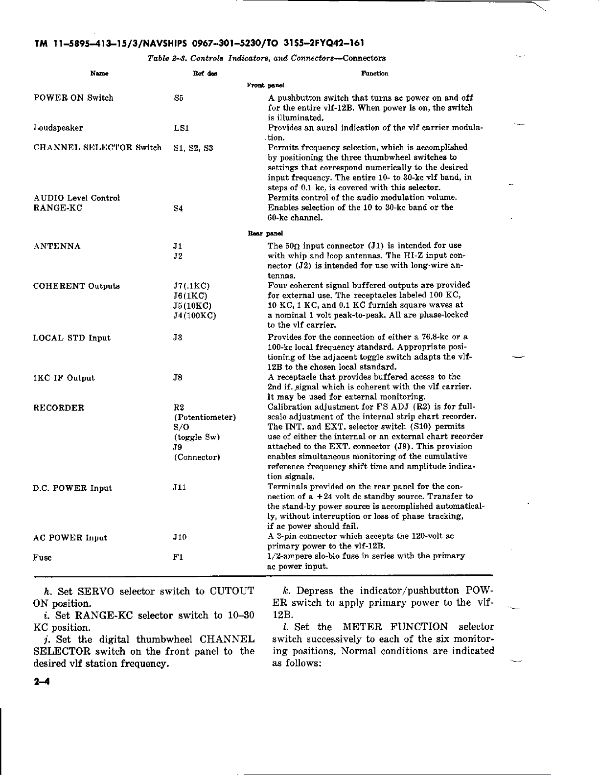
Table s.
N.D.
Controla
Ra,
67
-3()t -5;230
Indiaato$, ahil
U
tO 3t
/
55-2FYQ42-I 6l
Connectora-Qonnectrots
POWEB
Loudspeaker
ON Switch
CHANNEL SELECTOR Svritah
AUDIO Level
RANGE-KC
,A.NTENNA
COHERENT
trol
Co
Outputs
LOCAL STD Input
1KC IF Output
RECORDEB
D.C. POWER Input
AC
Fuse
POWER,
Input
s5
LS1
s1, s2, s3
s4
J1
J7(.rKC)
J6(1KC)
(10KC)
J5
J4(100KC)
J3
J8
R2
(Pot€ntiometer)
s/o
(toggle
J9
(Connector)
.I11
J10
F1
Sw)
pushbutton
A
for the entire vlf-128.
is illuminated,
Provides an aural indication of the
tion.
Permits frequency selection, which is
positioning
by
settings that correspond numerically
switch that turns ac
When
the three thumbwheel
porrer
power
is on, the Bwit h
vlf
accomplished
switches to
to the desired
input frequency. The entire 10- to 30-kc vlf
steps of 0.1 kc, is covered
Permits control of the audio modulation
Enables selection of the 10 to 30-kc band o!
60-kc channel.
Edr
DaD.l
The 50O input connector
vrith whip and loop antennas, The
(J2)
nector
tennas.
Four coherent
is intended for u8e with
sighal
for external use. The
KC, 1 KC,
10
a nominal 1 vott
vlf
to the
Provides for the connection of either
100-kc local frequency standard. Appropriate
tioning of the adjacent toggle
128 to the chosen local standard.
carrier.
A receptacle that
2nd if..signal which is
It may be
Calibration adjustment for
scale adjustment of tlle
The INT. and EXT. selector swit h
use of either
attached to the EXT. connector
enables sinultaneous monitoring of the cumulative
reference frequency shift time and amplitude
tion
Terminals
nection of a +24 volt dc standby source, Transfer
the stand-by
u6ed
signal6.
0.1 KC furnish square
and
peak-to-peak.
provides
for extarnal
internal or an extemal chart recorder
the
provided
po$r'er
tith
(r1)
buffered outputs
receptacles labeled
buffered access
coherent
FS
internal
on the rear
source is accomplished automatical-
ly, without interruption or loss ol
power
if ac
A 3-pin
primary power
1/2-ampere slo-blo fuse
ac
Power
should fail.
connector
to the Ylf-128.
input,
vrhich accepts the 120-volt ac
in
series with t}re
selector,
this
is intended
HI-Z ilput con-
long-wire at-
All are
a ?6.8-kc o! a
switch adapts the
with the
monitoling.
ADJ
st
(Jg).
panel
phase
(R2)
p
(S10)
chart recorder.
This
for the con-
on and off
carrier
modula-
band, in
volume.
the
for use
provided
are
100 KC,
waves at
phase-locked
posi-
to the
vlf
carrier.
is for fult-
pemits
provision
indica-
tracking,
primary
vlf-
tD
i.. Set SERVO
position.
ON
selector switch
i. Set RANGE-KC selector
position.
KC
Set the digital thumbwheel CHANNEL
r.
SELECTOR
desired
vlf station frequency.
switch
on the
front
to
switch to
panel
24
CUTOUT
10-30
to the
/r. Depress the indicator/pushbutton
ER
switch to apply
primary power
to the vlf-
r2B.
l.
the METER FUNCTION
Set
switch successively to each of the six
positions.
ing
as follows:
Normal
conditions
are indicated
POW-
selector
monitor-
7
g-r
at-
control,
of car-
DB
step
allorving
to charge
metel
rela-
particu-
of the
re-
switch
Mater Function
-12V
+72V
CARRIER
PHASE
l
OOKC
100PPS
rn. Adjust
if
necessary,
to bring
rier level into
ATTENUATION
sufficient time
between steps, until
reads
approximately
Metor
Red mark on right of center
Red mark on
grcen
In
tenuator
green
In
l.ocked.
grecn
In
green
In
DB ATTENUATION
green
switch
for
agc
tive signal strength
lar
transmitting
location
and antenna
ceiving station,
can be
preset
station and the
DB ATTENUATION
to the desired
rM l t
-5
lttdi,cation
right of center
proper
when
area
position
area
area
area
meter indication
ar.ea. Slowly
time constant
the front
center
is
selected.
phase-
\r'hen
downward,
panel
scale.
is knorvn for
geographical
characteristics
position.
895-4 r
If the
the
z. Set AIIDIO volume control to desired
volume
eration
or
u'ill
cation of negative change can be
the time difference
position
tained.
for continuous
Make
o.
SLEW. When
+
slew in a negative direction, and
quick
a
by setting
opposite indication will be
an
When the slew
monitoring.
check of
selector
set at
proper
switch to
-SLEW,
register. In the
check
is completed,
servo
op-
-SLEW
the servo
an indi-
observed at
SLEW
+
ob-
the SERVO selector switch should be re-
turned
procedure
mine u'hether the servo is tracking the
transmission. When the switch is returned
CUTOUT
should indicate the original reading or
which
mal
OUT ON. In this
automatically
falls
tracking,
carrier returns
can be made
tioning
this
and will
are below the
circuit.
to an automatic tracking
will enable the operator to deter-
the time difference
ON,
closely approaches the value. The nor-
position
below the level required for reliable
position
for the selector switch is CUT-
position
disconnected if the carrier level
and will be reconnected when the
to the
remain
to
the selector to
the servo is
allow tracking of weak
threshold level
proper
in operation by
CUTOUT OFF.
activated at all times
position.
the servo
level. The servo
signals
of the
This
vlf
register
number
will
posi-
which
cutout
5/3/NAVSHI
2-7.
been explained
most
and adjusting
equipment by deterrnininE
error drift of
with respect
quency
ments have
mined
comparison
fretluency
rived
follows:
ister readings
the interval
standard
difference
reading
the reading
to which
If
zero
once
difference
until
relative
quency
as an integral
A maximum
seconds
to
reading
recorder.
difference
be
uled
results
of
record.
calculated
In
PS 09 67
Utilizing
Source Comporison
o. Various
often used,
-3Ol -5230
VIF-I28
applications
previous
in
however, is that
precision
the local frequency
vlf standard
to a
broadcast.
b. After
preliminary
made
been
the vlf-lZB
that
measurements may be made and
standard corrections
by recording and
(1)
(2)
up a chart of time difference
Set
versus time, date,
recommended
manufacturer.
Take an initial reading of the time
register, and record and
versus
time. The numerical value of
is of importance only as a reference
all subsequent readings
preferred,
the
dial can be
at the beginning of
the reference
register must not
the entire
frequency
standard
possible.
is
(3)
Mark
near
(4)
Make
register
interval has
as before,
the
reading is
An
by use of
procedure
error between the local fre-
and the vlf signal is observed
time
difference in
cumulative error of 9999.9 micro-
the date
the stylus
a second
after
passed.
and make
also recorded
initial rate
the following
Af
:
--
Fractional
t
Difference
Elapsed
in
time in sec
I
lO
3 I
55-2
FYO42-I
6l
for Frequency
Adiustment
ond
for the vlf-12B
paragraphs.
frequency
rate of time
the
time and
have
rating
of
source
standard
The
fre-
checks and adjust-
it has been deter-
and
is tracking
properly,
may be de-
interpreting data as
reg-
and hour for
by the frequency
plot
the
compared.
are
manually set to
sequence,
the
but
is established, the time
readjusted
be
is completed. The
microseconds.
and time of initial
on the vlf-12B chart
reading of the time
previously
the
Record and
sure that the
sched-
plot
the
time
of the chart
of drift error
frequency
p
sec
x
10-
can be
relationshipr
:
error
2-5

TM r r
-5895-41
3-r5/3/NAVSHtpS
@67-3Or-523OltO 3rS5-2FyO42-t6t
Assume
a.m. on
p,m.
of the
The
net
6 hour
val
is 4376.5-4323.2,
Therefole
_53.3
22,500
The minus sign indicat'es that the
at the 6.25-hour interval
initial
reading
ard frequency is
in
the reading would imply
standard
comparison
lected vlf
tained from
realized,
of
the chart recorder
microsecond
scale
readings
indicates
in
frequency
register,
nent
record
frequency
sources
of
frequency
that the
particular
a
same day
difference in microseconds
and
15 minute
the fractional
and implies that the
register reading
day is 4376.5
the reading is 4323.2.
(22,500
or
-53.3
frequency error
:
x 10'"
-2.i]7
was
low. Conversely, an
frequency is high with respect to the
frequency derived from
carnier. Similar results
the chart recorder. It
however,
an increase
the
of
or
being
that
each
change. The
is important,
and the
error. Unlike
chart recorder
all variations
phase
compared,
difference
as s'ell
represents
direction of the off-
the time difference
drift trends
at 8:00
and at 2il5
over the
seconds)
mricroseconds.
x 10'
lower than
that the
local
inter-
is:
reading
the
stand-
increase
local
the se-
can be ob-
must be
off-scale reading
100-
a
since one direction
other a decrease
provides
in
as
and of
perma-
a
rerlative
the
bet*'een
indications
diurnal
the
changes
should
computed
ings.
steps
adjustments
along
be referred
from
(5)
The information
above
determine
standards.
oscillator
procedure.
2-8.
Although
lowing
it
helpful
is
for
the next
dure
can
a.
Set DB
db.
b.
Set SERVO
oN.
c.
Set
See instructions accompanying
standard
Stopping Procedure
no damage can
predetermined
a
be used.
AUDIO
d. Depress
power.
mary
Note.
\f
dc
battery
when
the equipment
drain
during
lt,e vlf-128
pack,
periods
the v,lf
propagation
path.
to when rate of drift
time difference register read-
obtained from the
can be used directly to make initial
on
the frequency standard or to
aging characteristics of crystal
the
for complete
be done by not fol-
shutdown
preset
to
operation.
ATTENUATION
POWER
the
the controls to be ready
The following
selector
volume
switch
control
switch
is supplied
power
dc
is shut
of inactivity.
should
down to
adjustment
procedure,
proce-
control to 80
to CUTOUT
midrange.
at
to shut off
with an
be
prevent
extemal
disconnected
battery
pri-
It
is
24
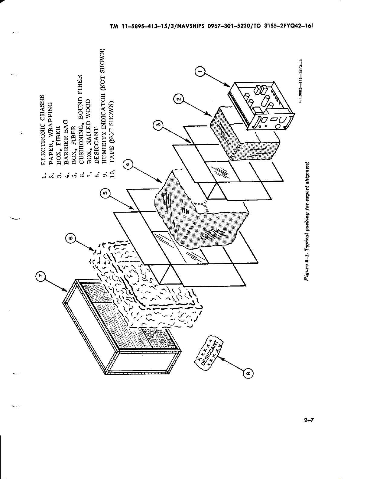
r-5895-4!3-1 s/3/NAVSHIPS
TIrt t
z
o
a
fr
E]
e
g,
-
r,r
Bo
22. ER
5H
Els*E9ptr-.
.
A\9)Ft,'1
9'E
Edr"tsr"9zP
(J
3?6{5s58
G]A14EPqOtqE
E1
.P(
."
v
C<
E2ZZ
-b rY
Hi
.lJ
AHt,
Fr
o
z
-^
<g
e6
Qli
zu)
*F
>
t->
6*
Frc
EA
p<
t^,
O967-W1-523O
3lS5-2FYQ42-I6I
llo
I
'i
I
1
J
n
teT,jJ:
z"l
-.'.74
.(iffig
);{}\ii}$(;)-
,12)'ll(\\;.')i$+)
*'SlS'^=u-)t
t
'\.
s\-,\J'.1'
S--E.-'.a-J
--,1
a*-
r-
J
:-:,.-
>-J
-:
1
-
t^:i
),
-
b
s
+
e.
E{
i
p
7-7
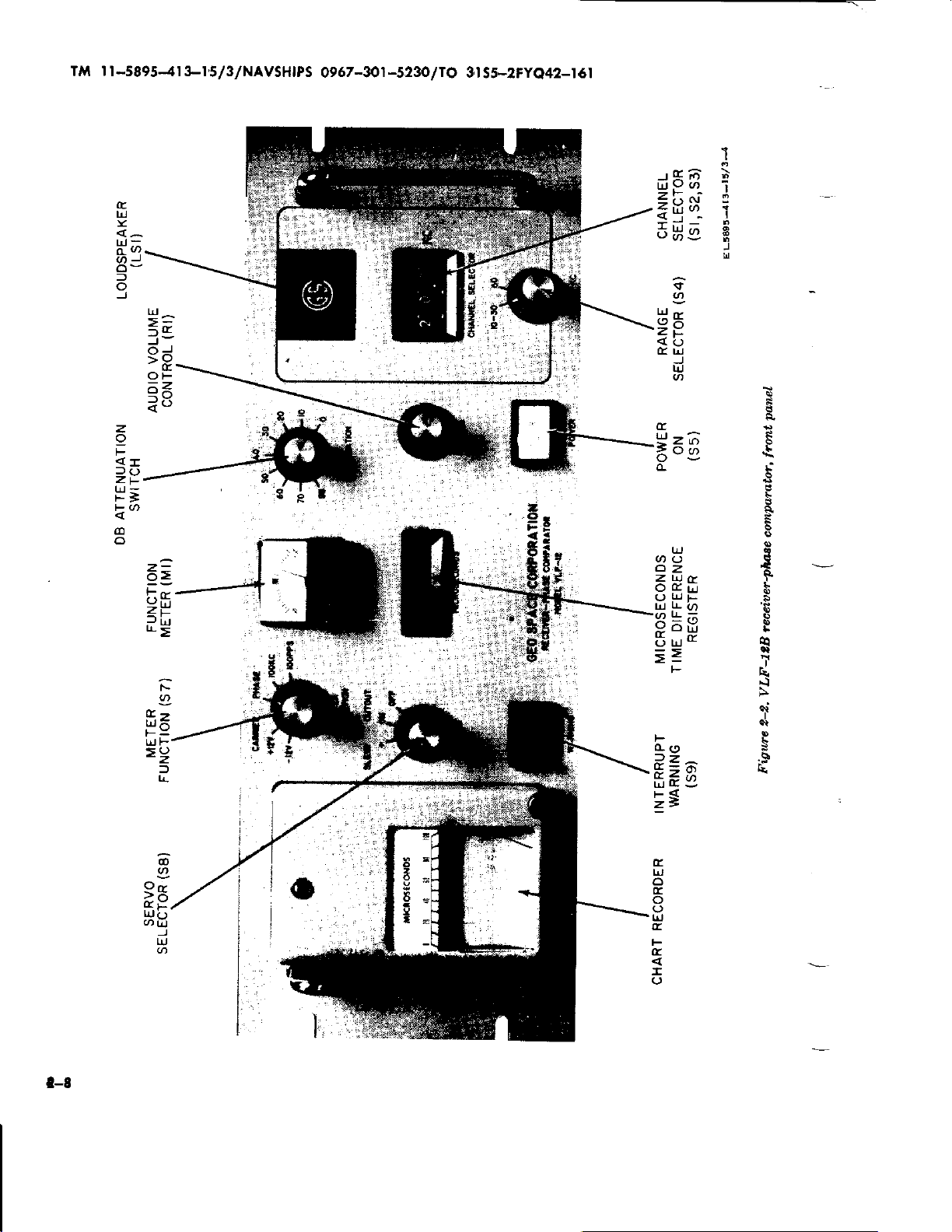
l
TM
t-5895-4r 3-r5/3/NAVSH|PS
0967-301
-5230
lto
3I
55-2Fyo42-r6t
1
(r
LrJ
li-
l
o
J
z
o
F
<I
lc,
Zt-
*';
t@
(o
o
1-
=e
tP
OF
d<
ao
6a
!:c
:E
r!>
lr
UJ
F
UJ
=
i/i
';
o
i
6Ue
=Es.
$
I
L!-
(9B
(-)
<
E lal
.J
!J
='68
UJ
(J
z
trtr
LL
LL;
oi
L!
=
F
t-
u)
z
o
F
z
l
F
cL(9
a"Ze
E
trl
z)
$
)
s.
s
s.
I-
L.)
o'
:i
a
T
a
I
l-8
:E
ts8
@
I
)
Lr.i
EuJ
6
(r
o
lrJ
E
F
(r
I
(J
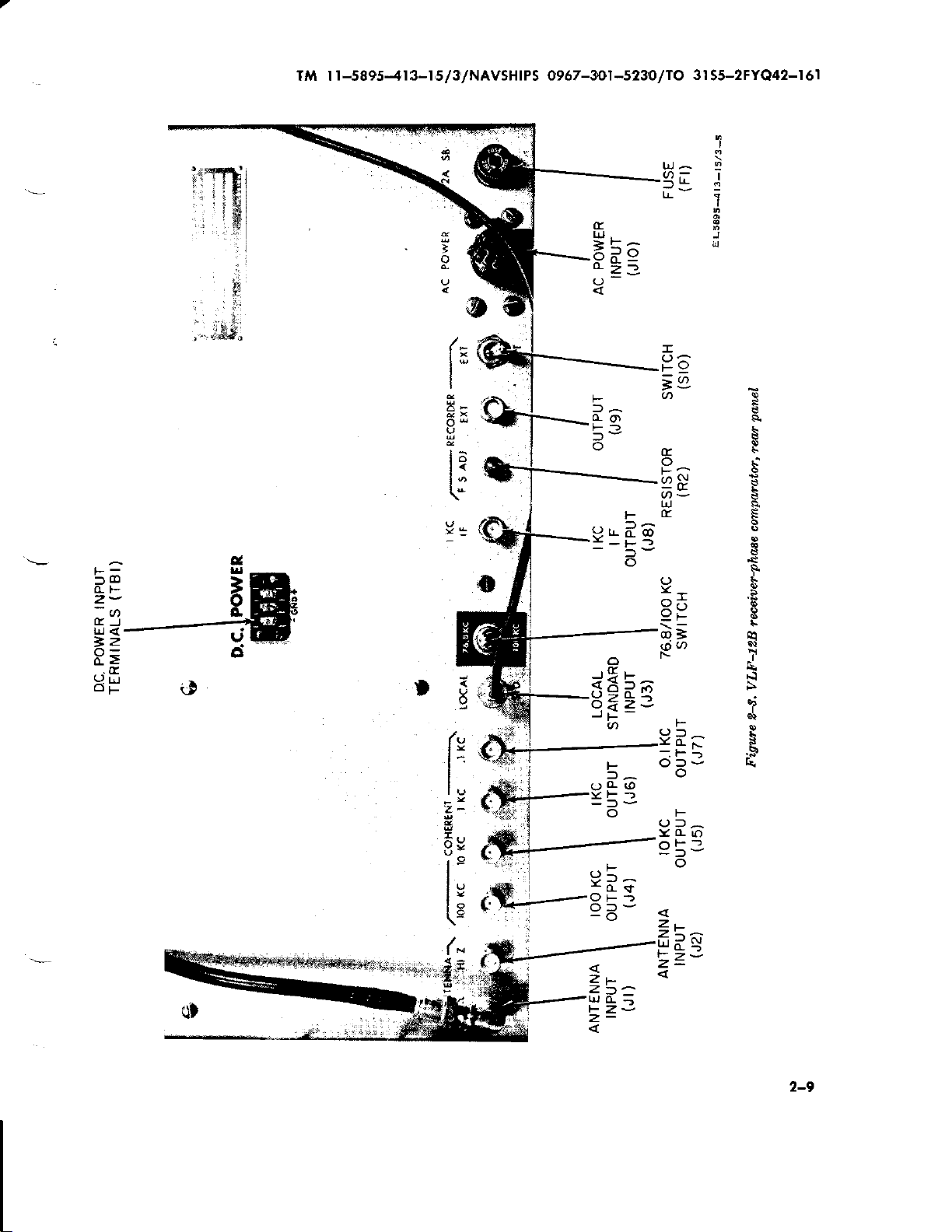
r-5895-413-r
Ti r
s/3/NAVSHTPS
]
o
I
I
O967-3O1-s23O/t O
trJ
^
u)=
(r
LU_
6?e
Q-
3rS5-2FYQ42-I6I
I
:
|
I
J
.-
s I
==
;>
8=
.E
3P$
0t
EB
"r'l
(,
o
f3
oq
la
lo
tU'
\-
t:
t"
3-
uv
ln
t:
("
e.
E
o
9
bp
IrJ
n
F
9rLdCo
-.-v
o
JSL^
o
3I d,",
o.a z
JF
a<)
F
l^
(Lcl
F_)
lv
-a
F
(LL
=^
F-
lv
o
F
ol^
Y(Ll.)
a.
E
+
a
I
s
?
ii
oi3
()-
Yde
OF
-o
Zt-
"'t
Z
Lrl
O_
t- Z-
z-
_)
-
-
o
ZL
freE
Z=
2-9
TM I
r
-589541
3-t,5/3
/NAVSH|PS
0967
-3O1
-5230
I O 3 I 55-2FYQ42-I
/
6l
CHAPTER
PRINCIPTES OF OPERATION
Section
l. GENERAT
3-l, lnlroduclion
This chapter
provides
eration for the vlf-128.
resses
frrom a
general
a detailed description of the various circuits
on a signal flow level. The block diagram dis-
cussion explains the
eration,
detailed functional theory of
the vlf-12B.
x'hile the circuit description furnishes
general principles
3-2. Funclionol Description
o. The underlying
can
best be understood by
operation
kilocycles, respectively.
plified
phase-shift
the
three frequencies
analogous
at
the selected incoming
servo
ficult
It is much
if
an input
I'esponse
assumed to have
with input signals of 10, 20, and 30
block diagram
principle
to a single
system is
to
consider under dynamic conditions.
easier to understand
condition is stated and the
js
assumed. Then after the servo is
individual leactions
can be checked
resDonse
can be assumed
(1)
In
and if
case I,
a convenient 10-microsecond
is assumed.
achieved
standard
to compensate
seconds.
After the
a null condition,
signal will have
for
will
This
principle
as it applies to each of
wherein the vlf-l2B is
phase
a closed-loop device, it is dif-
come to
through-out the system
proved
10-kc
a
the time shift
have occurred
principles
tt e
The
block
discussion
diagram
of
pmg-
level to
of op-
each element
of the vlf-12B
examination
Figure 3-1 is a sim-
of the
that demonstrates the
detector, operating
frerluency.
Since
the
the operation
proper
rest,
the resulting
correct the entire
to be correct,
input
signal with
step
phase
shift
servo system has
the corrected 100-kc
rotated
full
a
10
of
because
360"
micro-
when
3
DESCRIPTION
the vlfJ2B is tuned to 10 kc,
op-
100 kc is divided by
synthesizer
quency.
As
to
a
4.494 in
pmvide
the
the
proper
result of this division
the input to the 1st mixer is shifted
by 80.1'. Since both the incoming signal and
the
local oscillator have
resulting
a
ized at the first if. The mixing
of
quired
requires that the corrected 100
by 8.889. This
phase
tive
of the
phase
phase
by
the
shift
second
relationships are
difference
second mixer is 11.25
division ratio results in a
of 40.5'at the oscillator
mixer.
increasetl in
of
Once
again, since
increasing, a difference
of 3.6' will result in the l-ke IF signal. Since
the corrected 100-kc standard
by 100
frequency for
shift has
to achieve
result€d
kc inputs to the
by 3.6", a null
reached.
(2)
In case II, when the vlf-12B is tuned
to 20 kc,
phase
sent 72o. The servo system $'ill move until a
null has
it can
shift in the incoming signal will repre-
been
the required
phase
the
in
this
phase
condition has in fact
be
seen that a
reached,
compensating
has been divided
1-kc reference
detector, a 3.60
signal.
detector
l0-microsecond
time shift. This compensation is rrpresented
by 360' of the
synthesizer
by
3.101 rvith a resulting 116.10
in the local
phase
the di',rision factors of
difference of 44.10 in
tion signal
signal remain
resulting
phase
shifter.
In
lvill divide the corrected 100 kc
oscillator signal that
the first if.
the second mixer injec-
and the
the same, it can
phase
phase
changes are 40.5o
detector
be seen that the
the
corrected
local oscillator
process,
phase
in
phase,
is real-
kc.
This
divided
posi-
input
both
phase
both 1-
shifted
been
for
this
fre-
mixing
44.1"
frequency re-
kc be
Since
have
this case the
phase
produces
shift
Since
reference
and 360,
a
!!

respectively,
again
tion
has changed
has been
(3)
at the
ered
microsecond
of the input
the corrected
local oscillator
mixer output
logically,
and
same as
the
b. These
phase
quencies
rotations
the
standard
3-3.
tracking
time ermr
Simplified
e. General.
simplified
illustrates the
actual
are
gram
servo motor
shifting,
vlf-12B.
also represented.
shows a
ble to
electronic
sections
(1)
RF, lst and
audio
amplifiers,
(2)
the servo
cutout, sel,o
porting
The output
achieved
In case
input
time
signal.
1.00 kc
phase
will
the
in the
three
has
in the band
the
at
experienced
or the
The
block
main
All major
mechanical
to
the discussion
vlf-l2B's
servo systems.
are :
Receiver
2nd
Comparator
phase
motor
circuits.
logic
(3)Local
sisting
(VCO), phase
divider
needed to
oscillator signal.
rligital divider
100-kc signal
ternal
b. Recehser Section.
the simplified
of the
circuiLs
(4)
Reference
reference
synthesize
circuits that
from the
block
of the second
by 36',
III, a 30-kc
of the
shift
The
and a
the servo
by
signal
vlf-128 and
is reprcsented
synthesizer
by 2.367
of 1521''
shift
phase
a
har/e
remaining
previous
examples
been achieved
of
phase
incnming
Diogrom
Block
heavy black
diagram
signa'l
Although
provide
with
section----consisting
mixer stages,
agc circuits.
and
section-consisting
detector, servo
phase
oscillator
voltage-controlled
comparator,
and thumbwheel
the
divider
signals and
diagram
phase
two
demonstrate
interest, and
shifter
in either
signal.
shown
path
supporting
servo
necessary
the
follows
that
either mechanical
The major
amplifier,
shifter, and
synthesizer----con-
and
phaseJocked
chain-a series
divide
phase
shifter
buffered
For the discussion
(figure
mixer
null condi
system.
is consid-
10-
a
108"
by
will divide
+a
produce
The first
shift of
cases.
M.l"
shifts
are
that
fre-
all
at
the
that
will represent
local
the
in the
line
in figure
throuS:h
the block
that
is
functional
3-2
the
functions
dia-
utilizes
phase
applica-
or
of the
IF amplifiers,
of
servo
sup-
oscillator
the digital
switches
local
of
the corrected
into in-
outputs.
of
3-2),
is assumed
nected
is applied to
nal
former that
l0-kilohm input
the
amplifier.
gain
the rf
a
upon selection,
ing
bandpass
filter
illustrated
of the vlf
band.
a single
ter has
filter, the
the
attenuator
ments
switch.
a balanced
to
lator frequency
increments)
vide a
12.25
kc IF amplifiers
a
center
a
-r-
of
rapidly to 80
off
of center.
crystal
gain
Following
nal is applied
11.25-kc
corrected
dividing
mediate
the
coupled
amplifier,
,bandpass
the
c, Comparator Section.
1J<c filter
to the
and
nal from the
of the
the servo cutout
disconnect the
'level
it
servo
that a
to the 50-ohm
loop or
an antenna
couples
input.
the 50-ohm
circuit
The transfotmer
..,/-10,0-00760
of
amplifier,
filter.
has a bandpass
figure 3-3,
in
frequencies
If the
60-kc
channel
a bandpass
signal
that
by means
The attenuated
mixer.
above
first
kc. The stages
100 cps at the
intermediate
frequency
:
signal
the
either
to
At the 3-db
of from
in the
bandpass
at 60
approximately
of
is applied
adjustable
is
of the
The applied
is always
the
that follow
a crystal
and
of 12.25
3-db
db at
The if. amplifiers
filter are
of the
1-kc signal
falls too low for
phase
signal
amplification
signal,
5 kc
again by
frequency
to an output
and
is
servo
L2.25-kc if. amplifier
detector compares
used to
over a
to the
from the
second
obtained
provides
4,
of 1 kc.
is further
connector,
1-kc
to a
nominal 50
to a
applied
phase
to
phase
detector
that is used
servo system
whip antenna
The received
matching
broadband
of a
provides
14.14,
or
is
applied,
a 30-kc
points,
kc to
8
allowing
10-kc
filtel
is received.
kc
is
antenna
voltage
a
23 db.
depend-
or 60-kc
the 30-kc
30
coverage
to 30-kc
is selected,
This
2 kc. From
to an
10-db
in
front
signal
panel
is then
selector
local
(in
(IF)
the
which
pass
a
either
100-cps
to
12.25
incoming
frequency
filter
kc and
point's.
200 cps on
kc
siCnal
arc
Response
following
provide
very
12.25
at
mixer,
increased
narrow band.
kc, the
where
by multiplving
divider chain
a
From
amplified
by 9 and
second
this
to an
filter that
cps,
output of
The
the agc
detector.
controls
and also
restricts
phase
detector
The agc sigl-
the
operates
to automatically
when the
reliable tracking.
l-kc carrier
the
con-
sig-
trans-
to
RF
From
kc, as
fil-
80-db
incre-
routed
oscil-
pro-
of
12.25has
band
falls
side
the
sig-
the
a
inter-
point
and
audio
the
gain
carrier
The
v2
Trrl I I
."5
895-4 I
l3-r
5/3/NAVSH
CHAPTER 3
p5
r
A967
-3Ot
-5230
tO 31
I
55-2 FyO42-l
6t
PRINCIPLES OF
Section
3-1. lnlroduction
This
chapter
eratiotr for the vlf-lzB. The discussion
resses fmm a
a detailed
on a
signal
cussion
eration, while the
detailed functional
the vlf-12B.
provides
general
description of the
flow
level. The block diagram dis-
explains the
general
cilcuit description
theory of each element of
tLe
block
principles
diagram
various circuits
principles
furnishes
3-2. Functionol Description
a. The underlying
can best be understood
operation
liilocycles,
plified
phase-shift
the three
analogous
at the
setvo
ficult
It is
if
an input
lesponse
assumed
individual
can be
response
with input
respectively. Figure
block diagram that demonstrates the
principle
frequencies wherein
to a single
selected incoming frequency.
system is a closedJoop
to consider under dynamic conditions.
much
easier to understand the operation
condition is stated
is
assumed. Then after
have
to
leactions
checked and if
can be assumed
(1)
In case I,
a convenient l0-microsecond
is
assumed. After
achieved a null condition,
standard
to compensate for
seconds.
signal will have
This will have
principle
of the
by examination
signals of 10, 20, and 30
is
3-1
as it applies to each of
vlf-l2B is
the
phase
detector,
operating
Since the
device,
come to rest, the resulting
it is
and the
servo is
the
through-out the system
proved
correct the
to be correct.
a 10-kc input
signal with
step
phase
the servo system has
the
corrected 100-kc
the time
occurred
rotated
shift of 10 micro-
a full
because when
l.
GENERAT
of op-
priog:-
level to
of op-
vlf-12B
of
the
sim-
a
dif-
proper
entire
shift
360.
OPERAIION
DESCRIPTION
the vlf-l2B
100 kc
syntl.resizer to
quency.
the input to the lst mixeri is shifted
by
80.1". Since both the
is
tuned to 10
is divided by
4.49.1 in the local
provide
As a result of this division
kc, the corrected
proper
the
incoming signal
mixing fre-
oscillator
process,
in
the local oscillator have increased in
a resulting
ized
at the first if. The
quired
requires
phase
by the second mixer
that the corrected
difference of
mixing frequency re-
44.1o is real-
is 11.25 kc. This
100 kc be divided
by 8.889. This division ratio results in a
phase
tive
of the second
phase
of 3.6" will result in the l-kc
the
corrected
by 100 to achieve the required
frequency for the
shift
kc inputs
by 3.6",
reached.
to 20 kc, it can be seen
phase
sent
has
null
time shift. This
by 360"
synthesizer r.r,ilrl
by
3.101
in
the local oscillator
phase
the division
tion
signal
resulting
shift of 40.5'at the oscillator
mixer.
relationships
100-kc
Once again, since
increasing, a difference
are
IF
signal. Since
standard
has been divided
l-kc reference
phase
has
resulted in this signal. Since both
phase
the
to
null condition has in fact been
a
(2)
In case
II,
shift in the incoming signal will repre-
The
72o.
difference
signal and the
remain the
servo system {.ill
been reached, compensating for
compensation is represented
of the
phase
divide the corrocted 100 kc
rvith
a resulting 116.10
of 44.1" in
factors of the
same, it can be
phase
changes
detector, a 8.6'
detector
when the vlf-128 is tuned
that a
shifter. In this
signal that
second mixer injec-
phase
are 40.5o
have shifted
l0-microsecond
move
phase
produces
first
the
detector
seen that the
until a
case the
if.
reference
and 36.,
phase
and
phase,
posi-
input
both
phase
1-
this
shift
a
Since
Lt
Ti^ r I
-5895-4
r 3-r s/3/NAVSlltPS
09
67
-fi
t
-523a
I
tO
3I
S5-2FYO42-!
6t
respectively. The
again
tion
ered at the input
microsecond
of the input
the
local oscillator
mixer output
and
the
phase
quencies
rotations at the
the time error
standard or the
has ehanged
has been achieved
(3)
In case
time shift
signal.
corrected I00
phase
will
logically,
same as
b. These
tracking
the remaining
in the
three examples
has been achieved
in the band
experienced
3-3. Simplified
a. General.
simplified
illustrates the
actual
are
gram
servo motor
shifting,
ble to
electronic
sections are
vlf-l2B.
also
shows a
vtf-12B's
(1)
lst
RF,
audio
amplifiers,
(2)
the servo
cutout, servo
porting
log:ic
(3)
sisting
(VCO), phase
The heavy
block dia€ram
main sigaal
All
representd.
mechanical
to
the discussion
servo systems.
:
Receiver
2nd mixer
and
Comparator
phase
detector,
motor
circuits.
Local
of the
comparator,
output
III, a 30-kc signal
of
kc by 2.?67
have a
previous
phase
incoming
Block
provide
with either
section-consisting
and agc circuits.
osci'llator
voltage-controlled
of
the second
by 36', and a
the servo
by
vlf-l2B and
the
is represented
The synthesizer
tD
shift of
1521''
phase
shift of
phase
cases.
two
demonstrate
of interest, and
shifter
will represent
in either the
siSaal.
Diogrom
black
shown
path
major supporting
Although
servo that
the
that
The
stages,
line
in figure
through
the block
necessary
follows is applica-
mechanical
major functional
IF amplifiers,
seotion-consisting
servo amplifier,
phase
shifter, and
synthesizer---<on-
and
divider circuits and thumbwheel
needed to
oscillator signal.
(4)
digital divider circuits
100-kc signal from the
ternal reference signals and
b. Receioer
the simplified
synthesize the
Reference
divider chain-a series
Section,
block diagram
phaseJocked
that divide
phase
the corrected
shifter into in-
buffered
For the discussion
(figure
mixer
null condi-
system.
is consid-
10-
a
108'
by
will divide
produce
The first
44.1o
shifts
at
are
that
fre-
all
the
that
local
in
the
3-2
the
functions
dia-
utilizes
phase
or
of the
of
servo
sup-
oscillator
the disital
switches
local
of
outputs.
of
3-2),
is assumed that a
nected to the 50-ohm
nal is applied to an
former
the l0-kilohm input
amplifier.
gain
a
the
ing upon
bandpass
filter
illustrated
of the
band.
that couples
The transformer
of
r,/10-g-00750
rf amplifier,
selection, to
filter. At
has
a
in
vlf frequencies
If
the
a single channel
has a bandpass
ter
filter, the signal
the
attenuator
ments by means
slritch.
that
The attenuated
to a balanced
frequency
lator
increments) above
vide a first
kc. The stages that
12.25
IF
a
kc
a center
off
amplifiers
frequency
-r-
100 cps at the
of
rapidly to 80 db
of center.
crystal
gain
Following amplification
is
nal
11.25-kc
corrected
dividing
mediate frequency of
The if. amplifiers
filter are used
of the signal
applied
signal,
kc from the divider
5
again by
the 1-kc signal
coupled to an output
amplifier, and
the bandpass to a
c. Comparator Section.
loop or
the sigaal
bandpass
figure 3-3, allowing
60-kc bandpass
at 60
of
is adjustable
of the
mixer.
is
always
the
intermediate
and a
of 72.25
to the second
obtained by
4,
is further
to a
nominal
1*c filter is applied to the agc
and to the servo
nal from
of the
the
disconnect the servo
level falls too low for
it
servo
the
12.25-kc if. amplifier and
servo
cutout
phase
phase
phase
that is used to
detector compares
whip
antenna
input. The received
antenna
the 50-ohm
circuit
:
either a
the 3-db
of from 8
in
matching
antenna to
of a broadband
provides
14.14,
or 23 db.
is applied,
30-kc
points,
kc to
10-kc
the
filter is
kc is received.
approximately
is applied
to
in 10-db
front
signal
The applied
incoming
follow arc
crystal
points.
3-db
200
at
to
over a very
at
provides
panel
then
is
local oscil-
(in
kc
12,25
signal to
frequency
filter
kc
cps
a
a-nd
Response
on either
following
provide
narrow
12.25 kc, the
mixer, where
multiplying
chain
a second
1 kc. From
amplified
connector,
1-kc filter
'50
T)r.e
detector.
detector
system when
reliable tracking.
to an
that restricts
cps.
output
phase
The agc sig:-
controls the
also operates
automatically
the carrier
the 1-kc carrier
is con-
sig-
trans-
RF
voltage
a
From
depend-
or 60-kc
30-kc
the
30 kc,
coverage
as
to 30-kc
selected'
fil-
This
2 kc. From
an 80-db
incre-
selector
routed
100-cps
pro-
(IF)
of
72.25-
the
which
pass
this
has
band
falls
side
the
increased
band.
sig-
the
by 9 and
inter-
point
and
audio
the
of
detector
g:ain
The
a
3-2
 Loading...