

Page 1
GeoSIG Ltd, Wiesenstrasse 39, 8952 Schlieren, Switzerland
Phone: + 41 44 810 2150, Fax: + 41 44 810 2350
[email protected], www.geosig.com
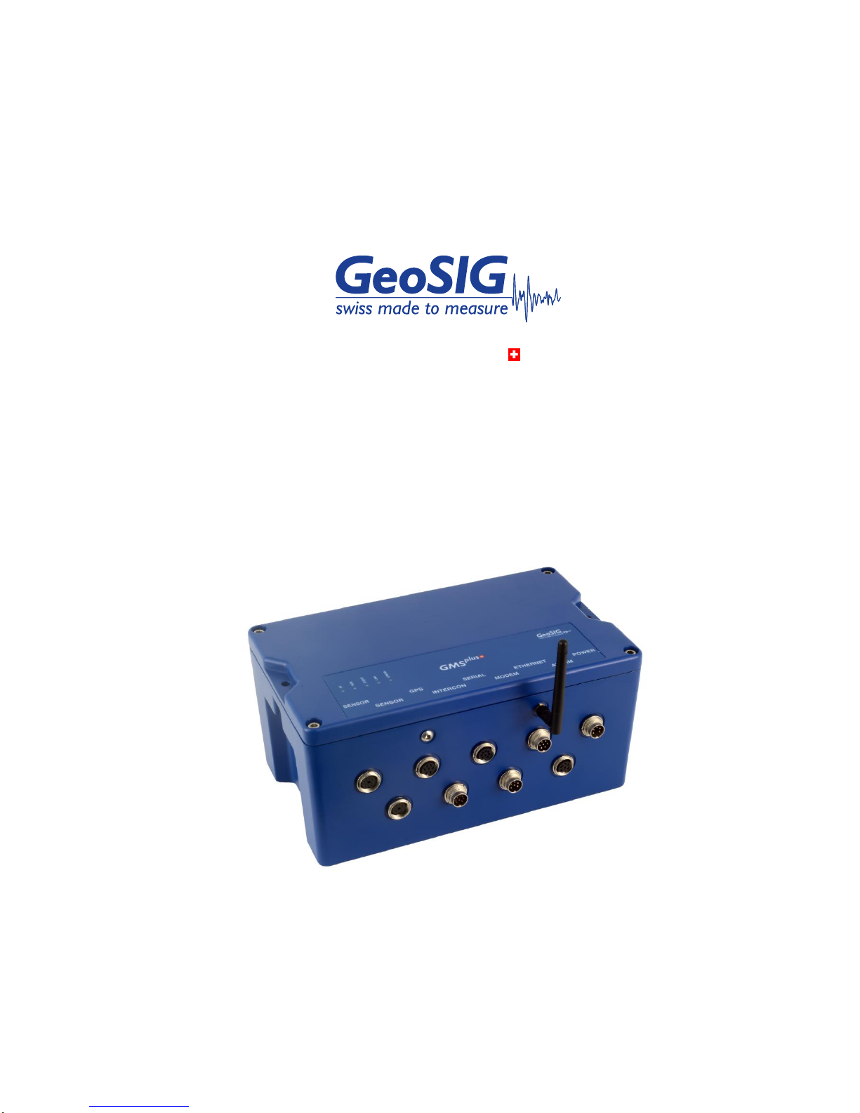
GMS
plus
User Manual
Page 2

GMSplus User Manual
2 / 124 20.06.2017 / V21
GS_GMSplus_UserManual_V21
Document Revision
Version
Date
Modification
Prepared
Checked
Released
1
29.08.2012
First release
MAE
FAR
MAE
2
25.09.2012
Minor corrections, chapter
13.3 added, Interface to
GeoDAS updated
MAE
FAR
MAE
3
07.12.2012
Adjustments for release
21.03.00: Seismometer
Control, Network Settings,
Communication
FAR
MAE
MAE
4
19.12.2012
Correction of spelling errors
and improvement of
description
TAB
MAE
MAE
5
10.04.2013
Fast USB-3G modem added
(chapter 10.8.3)
MAE
FAR
MAE
6
13.11.2013
Updates for the firmware
version 21.07.00
OLR
FAR
MAE
7
02.12.2014
Correction of spelling
mistake
VAG
JON
JON
8
09.12.2014
Updates for the firmware
version 21.11.00
OLR
JON
MAE
9
17.03.2015
Correction of spelling
mistake
VAG
JON
JON
10
24.03.2015
Improvement of description
VAG
JON
JON
11
15.04.2016
Updates of safety, chapters
3 and 4. Updated pictures.
JON,
REG.
TAB
JOG
JOG
12
19.05.2016
Update of section “safety
and warnings.”
JON
REG
JON
13
01.06.2016
Substantive editing and
proofreading
KAC
REG
JON
14
30.06.2016
Update of section “Warnings
and Safety.”
JON
REG
JON
15
20.07.2016
Description of menu item
“GeoSIG Options”
JON
KAC
JON
16
16.08.2016
Addition of “GeoSIG
Cybersecurity
Recommendations” section.
KAC
JON
JON
17
14.09.2016
Update of Table of Contents
VAG
JON
VAG
18
09.11.2016
Update of Index
VAG
JON
VAG
19
20.01.2017
Update Style page 22
VAG
VAG
VAG
20
28.03.2017
Update valid sample rates
JON
VAG
VAG
21
20.06.2017
Update of cross reference
VAG
REG
VAG
Disclaimer
GeoSIG Ltd reserves the right to change the information contained in this document without notice. While the information contained
herein is assumed to be accurate, GeoSIG Ltd assumes no responsibility for any errors or omissions.
Copyright Notice
No part of this document may be reproduced without the prior written consent of GeoSIG Ltd. Software described in this document is
furnished under a license and may only be used or copied in accordance with the terms of such a license.
Trademark
All brand and product names mentioned are trademarks or registered trademarks of their respective holders.
All rights reserved.
GeoSIG Ltd
Switzerland
Page 3

GMSplus User Manual
20.06.2017 / V21 3 / 124
GS_GMSplus_UserManual_V21
Table of Contents
Applicability of This Manual ................................................................................................. 7
Warnings and Safety ........................................................................................................... 7
GeoSIG Cybersecurity Recommendations ........................................................................ 10
Symbols and Abbreviations ............................................................................................... 12
1. Introduction .................................................................................................................... 13
2. Incoming Inspection ....................................................................................................... 13
2.1. Damage during shipment ...................................................................................................................... 13
2.2. Warranty ................................................................................................................................................ 13
2.2.1. Limitation of Warranty .................................................................................................................... 13
3. Storage (Instrument Shelf Life) ...................................................................................... 14
3.1. Main battery........................................................................................................................................... 14
3.2. Backup battery ...................................................................................................................................... 14
4. Description ..................................................................................................................... 15
4.1. Housing ................................................................................................................................................. 15
4.2. The housing lid ...................................................................................................................................... 15
4.3. Base plate ............................................................................................................................................. 16
4.4. Connectors ............................................................................................................................................ 16
4.4.1. Standard External Connectors....................................................................................................... 17
4.4.2. Optional External Connectors ........................................................................................................ 18
4.4.3. Optional External Antennas ........................................................................................................... 21
4.4.4. Connectivity Options ...................................................................................................................... 21
4.4.5. Internal Connector ......................................................................................................................... 22
4.5. Visual Indicators .................................................................................................................................... 22
4.5.1. Detail Description ........................................................................................................................... 23
4.6. Internal Batteries ................................................................................................................................... 25
4.6.1. Main Battery ................................................................................................................................... 25
4.6.2. Backup battery ............................................................................................................................... 26
4.7. Power Supply ........................................................................................................................................ 26
4.7.1. Choice of Power Supply ................................................................................................................ 26
4.7.2. Automatic Power On and Off ......................................................................................................... 26
4.8. Supplied and Optional Accessories ...................................................................................................... 27
4.8.1. Standard Supplied Accessories ..................................................................................................... 27
4.8.2. Optional Accessories ..................................................................................................................... 27
5. Installation ..................................................................................................................... 28
5.1. Site Selection ........................................................................................................................................ 28
5.1.1. Environmental Considerations ....................................................................................................... 28
5.1.2. Power Supply Considerations........................................................................................................ 28
5.1.3. Communication Considerations ..................................................................................................... 29
5.2. Installation ............................................................................................................................................. 29
5.2.1. Requirements for the Instrument Foundation ................................................................................ 29
Page 4

GMSplus User Manual
4 / 124 20.06.2017 / V21
GS_GMSplus_UserManual_V21
5.2.2. Mounting the Instrument ................................................................................................................29
5.2.3. Orientation, Levelling and Calibration of the Sensor .....................................................................30
5.2.4. Supply Voltage ...............................................................................................................................30
5.2.5. Installing other Components, Options, Accessories ......................................................................30
5.3. First Start and Communication Setup ...................................................................................................31
6. Principle of Operation of the Instrument ......................................................................... 32
6.1. Normal Operation ..................................................................................................................................32
6.2. Behaviour on a Seismic Event ..............................................................................................................32
6.3. Firmware and Configuration Upgrade ...................................................................................................34
6.4. Backup Server .......................................................................................................................................34
7. Quick Start Up ................................................................................................................ 35
7.1. Preparation ............................................................................................................................................35
7.2. Set IP Address of the Instrument ..........................................................................................................35
7.3. No Stations Configured at first Start Up ................................................................................................37
7.4. Adding New Stations… .........................................................................................................................38
7.5. Configuration of Data Server .................................................................................................................39
7.6. Basic Configuration of the Instrument ...................................................................................................40
8. Network Settings ............................................................................................................ 43
8.1. Network Settings through the Web Interface or Instrument Setup… ....................................................43
8.2. Network Settings through GeoDAS .......................................................................................................44
8.3. Wired Ethernet settings through the local Console ...............................................................................45
8.4. Wireless Settings through the local Console .........................................................................................45
8.5. Get IP from Instrument ..........................................................................................................................47
9. The Web Interface ......................................................................................................... 48
9.1. Accessing the Web Interface .................................................................................................................48
9.2. The Home Panel and the General Navigation ......................................................................................49
9.3. Device Configuration .............................................................................................................................50
9.3.1. armdas Configuration .....................................................................................................................51
9.3.2. Manage armdas Configurations .....................................................................................................52
9.3.3. Network Configuration ...................................................................................................................53
9.3.4. Web Interface Configuration ..........................................................................................................54
9.4. State of Health .......................................................................................................................................54
9.4.1. Error Status ....................................................................................................................................54
9.4.2. Recording Status............................................................................................................................56
9.4.3. Hard- and Software Status .............................................................................................................57
9.4.4. Requests ........................................................................................................................................58
9.5. Data Explorer .........................................................................................................................................59
9.6. Help .......................................................................................................................................................60
9.6.1. Online Help ....................................................................................................................................60
9.6.2. Contact GeoSIG Service ................................................................................................................60
10. Detailed Configuration of the Instrument ...................................................................... 61
10.1. Switch ON and OFF the instrument ....................................................................................................61
10.2. General Comments to the Configuration .............................................................................................61
10.2.1. Change Configuration by the Web Interface ................................................................................61
Page 5

GMSplus User Manual
20.06.2017 / V21 5 / 124
GS_GMSplus_UserManual_V21
10.2.2. Change Configuration by GeoDAS .............................................................................................. 61
10.2.3. Changing Configuration by the Console ...................................................................................... 62
10.2.4. Explanation of the Structure in the Manual .................................................................................. 63
10.3. Configuration of the Channels............................................................................................................. 64
10.3.1. In the Web Interface or by GeoDAS ............................................................................................ 64
10.3.2. Via Local Serial Console .............................................................................................................. 65
10.3.3. Calculation of the LSB factor ....................................................................................................... 67
10.3.4. Channel Naming .......................................................................................................................... 69
10.4. Configuration of Data Streams ............................................................................................................ 69
10.4.1. In the Web Interface or by GeoDAS ............................................................................................ 69
10.4.2. Via Local Serial Console .............................................................................................................. 70
10.4.3. Set up of Data Streams ............................................................................................................... 71
10.5. Trigger Settings ................................................................................................................................... 74
10.5.1. In the Web Interface or by GeoDAS ............................................................................................ 74
10.5.2. Via Local Serial Console .............................................................................................................. 75
10.5.3. STA/LTA trigger ........................................................................................................................... 78
10.5.4. Trigger Weight ............................................................................................................................. 78
10.5.5. Trigger Time Frame ..................................................................................................................... 78
10.5.6. Trigger Interconnection over LAN ................................................................................................ 79
10.6. Preset Trigger Settings ....................................................................................................................... 83
10.6.1. In the Web Interface or by GeoDAS ............................................................................................ 83
10.6.2. Via Local Serial Console .............................................................................................................. 84
10.7. File Storage and Policy ....................................................................................................................... 85
10.7.1. In the Web Interface or by GeoDAS ............................................................................................ 85
10.7.2. Via Local Serial Console .............................................................................................................. 86
10.8. Communication Parameters................................................................................................................ 88
10.8.1. In the Web Interface or by GeoDAS ............................................................................................ 88
10.8.2. Via Local Serial Console .............................................................................................................. 89
10.8.3. Connection over PPP (Cellular Modem or Analog Phone Line) .................................................. 91
10.9. Miscellaneous Parameters .................................................................................................................. 96
10.9.1. In the Web Interface or by GeoDAS ............................................................................................ 96
10.9.2. Via Local Serial Console .............................................................................................................. 97
10.9.3. Time synchronization ................................................................................................................. 101
10.10. GeoSIG Options .............................................................................................................................. 102
10.10.1. Via Local Serial Console.......................................................................................................... 102
10.11. Other Options in the Instrument Main Menu ................................................................................... 103
10.11.1. User requests .......................................................................................................................... 104
11. Test and Configuration Menu .................................................................................... 106
11.1. Flash Images and Boot Options ........................................................................................................ 107
11.2. Hardware Setup and Monitor ............................................................................................................ 108
11.3. Test Functions ................................................................................................................................... 108
11.4. Security ............................................................................................................................................. 108
11.5. Comparison of User Permissions ..................................................................................................... 108
12. Firmware Upgrades ................................................................................................... 109
13. Remote Access to the Instrument over SSH ............................................................. 111
Page 6

GMSplus User Manual
6 / 124 20.06.2017 / V21
GS_GMSplus_UserManual_V21
13.1. SSH Clients for Linux OS ..................................................................................................................111
13.2. SSH Clients for Windows OS ............................................................................................................112
13.3. SFTP access for Windows OS ..........................................................................................................113
13.4. File structure of the instrument ..........................................................................................................114
14. GeoDAS Settings ....................................................................................................... 115
14.1. Configuration of Stations ...................................................................................................................115
14.1.1. Add a new Instrument ................................................................................................................116
14.1.2. Remove an Instrument ...............................................................................................................116
14.2. Configuration of Server Parameters ..................................................................................................117
14.3. Instrument Control in GeoDAS ..........................................................................................................118
14.3.1. More Information… (State of Health of the Instrument) .............................................................118
14.3.2. Instrument Setup… ....................................................................................................................119
14.3.3. Cancel Pending Request ...........................................................................................................119
14.3.4. GMS Communication Interface ..................................................................................................120
14.4. Open recorded miniSEED files in GeoDAS ......................................................................................121
14.4.1. Save predefined Scaling Factors ...............................................................................................122
14.4.2. Calculation of the Scaling Factors .............................................................................................122
Index ................................................................................................................................ 124
Table of Tables
Table 1, Storage instruction ............................................................................................................................. 14
Table 2. Indicators description ......................................................................................................................... 22
Table 3. Main battery specification .................................................................................................................. 25
Table 5. Backup battery specification .............................................................................................................. 26
Table 6. Backup battery models ...................................................................................................................... 26
Table 7. The overall error states shown in the Web Interface ......................................................................... 49
Table 8. The overall error states shown in the Web Interface ......................................................................... 55
Table 9. Explanation table structure ................................................................................................................ 63
Table 10. Channel configuration menu structure............................................................................................. 66
Table 11. LSB of all GeoSIG sensors .............................................................................................................. 67
Table 12. Data streaming configuration menu structure ................................................................................. 71
Table 13. Trigger configuration menu structure ............................................................................................... 77
Table 14. Preset trigger configuration menu structure .................................................................................... 85
Table 15. File Storage and Policies menu structure ........................................................................................ 87
Table 16. Communication Parameters menu structure ................................................................................... 90
Table 17. Server Parameters menu structure ................................................................................................. 91
Table 18. Miscellaneous Parameters menu structure ................................................................................... 101
Table 19. Comparison of test and configuration menu users ........................................................................ 108
Table 20. Scaling factors of different sensors ............................................................................................... 123
Page 7
GMSplus User Manual
20.06.2017 / V21 7 / 124
GS_GMSplus_UserManual_V21
Applicability of This Manual
GMS Instruments are constantly being improved. Although the manual you receive along with your
instrument corresponds to the actual software versions, you are advised to check the GeoSIG web page
periodically for the most recent version of this document, and especially after performing any software
upgrades. This manual is based on the following software and firmware versions:
Component
Description
Required version or higher
GeoDAS
Data acquisition and analysis software on the
computer
2.28
armdas
Data acquisition software of the instrument
21.11.00
RTC
Real time clock
80.02.02
DSP
Digital signal processor
51.03.00
U-Boot
U-Boot bootloader
2013.01-r1
Web Interface
Web Interface
1.8-r1
Linux OS
Root file system
Kernel Version
rootfs-gms-102
2.6.39.4-r7
Warnings and Safety
STATIC ELECTRICITY
The instrument and its sensor unit (if available) contain CMOS devices and when serviced, care must
be taken to prevent damage due to static electricity. This is very important to ensure long-term
reliability of the unit. Such risk exists when both the instrument cover and the front panel are
removed.
INSIDE THE INSTRUMENT (MAINTENANCE)
When it is desired to fully restrict the access to the unit so that even its cover cannot be removed,
lockers can be mounted in the middle of the handles, on the side of the instrument. Under normal
circumstances, there is no need to remove the front panel of the instrument. In any case, only a
trained person should remove the front panel. Moreover untrained access may lead to serious
damage to the instrument, as well as may void the warranty. If the equipment is used in a manner not
specified by the manufacturer, the protection provided by the equipment may be impaired.
Before removing the front panel:
1. Turn the unit off
2. Disconnect all cables connected to the unit
3. Disconnect the battery
4. Make sure that all LED indicators are OFF
INSTALLATION SITE
This instrument is designed for highly specialized applications. If installed in publically accessible
areas it is the responsibility of the instrument owner to ensure that the device is installed in a safe
and secure manner.
The instrument should be installed in a well ventilated place and when possible be protected from
direct sunlight and heat.
The housing provides no protection against explosive atmosphere. The instrument must not be
operated without necessary protective measures (e.g. EX-proof housing) in an area where explosive
gases could be present.
BATTERY (MAINTENANCE) AND SAFETY
Page 8
GMSplus User Manual
8 / 124 20.06.2017 / V21
GS_GMSplus_UserManual_V21
The instrument is usually shipped with an internal rechargeable battery (main battery), which is an
optional accessory.
In addition there is a non-rechargeable button battery (backup battery) on the circuit board of the
instrument.
NEVER use any battery other than the ones supplied or approved in writing by GeoSIG.
An external power module, which is an optional accessory, is also usually shipped with the
instrument.
NEVER use any other power module than the one supplied or approved in writing by
GeoSIG.
Do not forget to connect the main battery when installing the instrument. The main battery is
provided with a short cable that has a polarised connector to avoid any wrong connections. Please
ensure that this connector is fully inserted and secured on the mating connector inside the
instrument.
CAREFULLY observe the polarity,
when replacing the main battery:
RED cable = (+) plus terminal of the battery
BLACK cable = (–) minus terminal of the battery
when replacing the button backup battery:
(+) sign marked on the battery
Any battery MUST be replaced by following its manufacturer’s instructions regarding
actual operating conditions AND latest by the end of below mentioned replacement
intervals to prevent data loss and to avoid safety related issues:
Battery
Battery model
Replacement interval
Main Battery (Internal)
FIAMM FG20721, 12V 7.2Ah
3 years from date of production
1
Yuasa NP7-12, 12V 7Ah
3 years from date of production1
FIAMM 12FGHL34, 12V 9Ah (long life)
8 years from date of production1
Button Backup Battery
Renata CR2430 MFR, 3V, 285mAh
5 years from date of production1
Duracell CR2430, 3V, 285mAh
5 years from date of production1
EEMB CR2430, 3V, 270mAh
5 years from date of production1
1
assuming operation at a steady 20°C or below.
The expected lifetime of a battery can drastically change depending on operating conditions. Strong
discharge of the battery and extreme temperatures must be avoided as per specific battery
manufacturer’s recommendations and guidelines.
Lifetime and replacement intervals mentioned in this manual are based on a constant ambient
temperature of 20°C or below. If this condition cannot be met the user must check with the
documentation of the battery manufacturer for information about the battery lifetime at elevated
temperatures.
When replacing the battery only newly manufactured batteries may be installed. The replacement
interval specified above starts from the manufacturing date of the battery, which is typically found
printed on the battery itself. When replacing the battery it is the users’ responsibility to update the
“battery installation dates” parameter in the configuration as described in chapter 11.2. This
parameter is used to issue a warning of required battery change.
For safety reasons the battery and operating conditions have to be annually checked to ensure that it
is still within the manufacturer’s recommended operational criterion.
It is important that all necessary precautions about operating a battery, such as the ones installed in
the instrument, are taken into consideration and the safety instructions are followed accordingly.
Page 9

GMSplus User Manual
20.06.2017 / V21 9 / 124
GS_GMSplus_UserManual_V21
The internal main battery (if installed) is a Lead Acid-type battery and is classified as “dangerous
waste”. The user is obliged to follow local laws and manufacturer’s guidelines for safe use and
correct disposal of any battery.
Lack of care or misuse of the battery as per battery manufacturer’s recommendations can be
hazardous, may damage your instrument and may even cause explosions. Please consult the battery
manufacturer’s website for the latest operating, maintenance and safety guidelines. Please contact
GeoSIG in writing if the specific safety, operating, maintenance and disposal information for your
battery type can’t be found.
SD AND COMPACT FLASH CARDS
SD and compact flash cards are available in a variety of quality levels on the market. This results in
problems with compatibility due to memory layout, signal structuring and power requirements.
Additionally some SD and compact flash card manufacturers refuse to provide adequate information
or factory controls to ensure that the product being sold today is the same as the product sold earlier
under the same part number.
Therefore GeoSIG cannot guarantee a SD or compact flash card will work in a GeoSIG instrument
unless it is purchased through GeoSIG. The SD and compact flash cards provided by GeoSIG are
tested and certified in house to work with the related GeoSIG instrument and industrial rated for
harsh environment conditions as extreme temperatures, shock, and vibration.
CLEANING
Disconnect the power from the instrument prior to cleaning. Do not remove the cover during
cleaning. Wipe all exterior surfaces with a damp cloth. Use mild detergent if required. No water
should be used if cleaning inside the instrument is required.
HOUSING LID
In case your GMSplus does not have a lid with holes as described in chapter 4.2 you must contact
GeoSIG to order a replacement lid.
Page 10

GMSplus User Manual
10 / 124 20.06.2017 / V21
GS_GMSplus_UserManual_V21
GeoSIG Cybersecurity Recommendations
GeoSIG instruments, as described in their documentation, have built-in security and safety features against
unauthorised access or use. However, ultimately it is the user’s responsibility to ensure the safe and secure
usage of our instruments based on their actual implementation. No factory delivered solution can fit each and
every possible scenario. The user is advised herein that once you connect a device to a network, you are
also connecting that network to that device. It is the responsibility of the user to take appropriate precautions
so that all devices should be adequately hardened, such as with individual strong passwords, and should
have their traffic monitored and managed via appropriate security features, such as firewalls. Also, noncritical devices should be segmented away from networks that contain sensitive information.
Compliance with a well-defined security procedure helps protect not only an individual device, but also other
devices connected through the network. Such procedure would be intended to prevent exploitation of an
individual device’s resources by unauthorized individuals, including the use of such device to attack other
systems on the network or the Internet.
The following recommendations can be considered in establishing such a security procedure:
1. Physical access restriction
All devices must be restricted from unauthorised physical access and a well-defined physical access
procedure shall be utilised.
2. No Unattended Console Sessions
Except for the devices which are physically secured, no unattended console sessions shall be left running.
3. No Unattended Network Sessions
No unattended user interface sessions shall be left running towards any device accessed through its network
interface.
4. Use of a Firewall
For a network that has any connection to the outside world, a hardware firewall must be running and
configured to block all inbound traffic that is not explicitly required for the intended use of the network and the
connected devices. The user can also consider limiting outbound traffic.
a
Any communication ports that are required for the operation must be protected.
5. No Unnecessary Services or Ports
If a service or port is not necessary for the intended purpose or operation of the device, that service must not
be running and the port must be closed. (e.g. if seedlink server is running, but not used, turn it off)
6. Use of authentication
Network and console device access must require authentication by means of strong and individualised
passwords per device (no passe-partout passwords).
Wireless access must require strong encryption to associate (such as WPA2), or some other strong
mechanism to keep casual users near the access point from using it to get full access to the network. WEP
or MAC address restrictions do not meet this requirement.
Page 11
GMSplus User Manual
20.06.2017 / V21 11 / 124
GS_GMSplus_UserManual_V21
7. Password complexity and security
When passwords are used, they must meet the specifications similar to below:
a
All default passwords must be changed at time of initial access or latest at deployment
into service.
Passwords MUST:
contain eight characters or more
contain characters from AT LEAST two of the following three character classes:
Alphabetic (e.g., a-z, A-Z)
Numeric (i.e. 0-9)
Punctuation and other characters (e.g., !@#$%^&*()_+|~-=\`{}[]:";'<>?,./)
8. Privileged Accounts
Privileged and super-user accounts (Administrator, root, etc.) must not be used for non-administrator
activities. A secure mechanism to escalate privileges with a standard account is acceptable to meet this
requirement. Network services must run under accounts assigned the minimum necessary privileges.
9. No Unencrypted Authentication
All network-based authentication must be strongly encrypted. In particular, insecure services such as Telnet,
FTP, SNMP, POP, and IMAP must not be used or must be replaced by their encrypted equivalents.
10. Software / Firmware updates
Networked devices must only run software/firmware that are updated according to supplier’s guidelines. A
periodical check of any available updates from the supplier must be sought.
Please contact GeoSIG Ltd if you require any further advice or clarification.
Page 12
GMSplus User Manual
12 / 124 20.06.2017 / V21
GS_GMSplus_UserManual_V21
Symbols and Abbreviations
ADC
Analog to Digital Converter
ARM
Main processor
Bootloader
First program executed when unit starts
CF
Compact Flash, memory card using Flash memory
Compact Flash
See CF
DSP
Digital Signal Processor in charge of controlling the ADCs
EEW
Earthquake Early Warning
Flash
Program storage memory device. It contains the Linux file system in Read Only
mode and some block areas under direct control of main program or bootloader.
GPS
Global Positioning System
GUI
Graphical User Interface
LAN
Local Area Network, a simple branch of private network using private IP address. It
could have or not have access to Internet (WAN).
NTP
Network Time Protocol
PPS
Pulse Per Second
RAM
Random Access Memory
RTC
Real Time Clock
SD
Secure Digital Memory Card
SPS
Samples Per Second
SSH
Secure Shell
SSID
Service Set Identifier. This is the identifier name of a wireless network.
STP
Shielded Twisted Pair
UTP
Unshielded Twisted Pair
VPN
Virtual Private Network
WAN
Wide Area Network. It is a network connection established between 2 LAN or a LAN
and a server over the internet (usual case) or through a rented link.
WPA
Wi-Fi Protected Access. It is a secure specification that allows users to access
information instantly via wireless link. It is a more modern and secure link than the
WEP type.
WEP
Wired Equivalent Privacy
Caution. Refer to the instructions next to the marking, or refer to the relevant
section of this user manual.
Direct current. This symbol indicates a direct current (DC) power line derived from
an alternating current (AC) power source.
Earth terminal.
CE. This symbol indicates that the device conforms to all legal requirements
needed to achieve free movement and sale of the product through the European
Economic Area (EEA).
Page 13

GMSplus User Manual
20.06.2017 / V21 13 / 124
GS_GMSplus_UserManual_V21
1. Introduction
Dear Valued GeoSIG Customer, thank you for purchasing this product.
These instruments have been optimised to meet the requirements of the majority of customers out of the box
and may have even been delivered tailored to your needs. In any case, to be able to get the most out of our
product, please carefully study this manual, its appendices and referenced manuals, as well as any other
documents delivered with it.
This is a reliable and easy to use device, and at the same time a sophisticated product that requires care,
attention and know-how in configuring, installing, operating and maintaining.
GeoSIG continually improves and enhances capabilities of all products. There may be several other
connectivity, hardware or software options for the instrument, which are not covered in this manual. Refer to
separate documentation from GeoSIG about available options or ask GeoSIG directly.
2. Incoming Inspection
All instruments are carefully inspected both electrically and mechanically before they leave the factory.
Please check if all received items correspond with the packing list and your order confirmation. In case of
discrepancy please contact GeoSIG or your local representative immediately.
2.1. Damage during shipment
If requested at the time of order, all instruments can be insured prior to shipment. If you receive a damaged
shipment and shipping insurance was previously arranged you should:
Report the damage to your shipper immediately
Inform GeoSIG or your local representative immediately
Keep all packaging and shipping documents
a
Insurance claims may be void if the above procedure is not followed.
2.2. Warranty
GeoSIG Ltd (hereafter GeoSIG) warrants hardware and software products against defects in materials,
workmanship and design for the defined period in the relevant contract or offer, starting from date of
shipment and five years parts and maintenance support commitment. If GeoSIG receives notice of such
defects during the warranty period, GeoSIG shall at its option either repair (at factory) or replace free of
charge hardware and software products that prove to be defective. If GeoSIG is unable, within a reasonable
time, to repair or replace any cabinet to a condition as warranted, the buyer shall be entitled to a refund of
the purchase price upon return of the cabinet to GeoSIG. Half (50%) of freight charges on shipments of
warranty repairs or replacements will be borne by GeoSIG (normally one way freight).
2.2.1. Limitation of Warranty
The foregoing guarantee shall not apply to defects resulting from:
Improper or inadequate maintenance by buyer
Buyer supplied software or interfacing
Unauthorised modification or misuse
Operation and storage outside of the environmental specifications of the instrument
Related to consumables or batteries
Improper preparation and installation at site.
Page 14
GMSplus User Manual
14 / 124 20.06.2017 / V21
GS_GMSplus_UserManual_V21
3. Storage (Instrument Shelf Life)
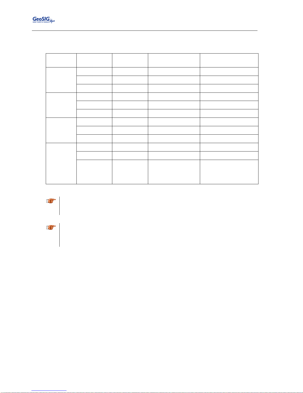
In case the instrument is stored, the batteries have to be maintained according to the storage duration.
Period of
time
External
power supply
Instrument is
operating
Main battery
Real Time Clock
backup battery
< 1 month
ON
YES
Connected
Connected
ON
NO
Connected
Connected
OFF
NO
Connected
Connected
1 – 3
months
ON
YES
Connected
Connected
ON
NO
Connected
Connected
OFF
NO
Disconnected
Connected
3 – 6
months
ON
YES
Connected
Connected
ON
NO
Connected
Disconnected
OFF
NO
Disconnected
Disconnected
More than 6
months
ON
YES
Connected
Connected
ON
NO
Connected
Disconnected
OFF
NO
Disconnected, must
be recharged every 6
months for at least
24 hours.
Disconnected
Table 1, Storage instruction
a
Removing or replacing the backup battery must be done by a trained person only. Therefore if
the instrument is stored for more than three months, always have it connected to power and let
it run.
a
If the instrument is stored for longer than 3 months, the battery must be removed from the
instrument and stored elsewhere in a well ventilated location as per the battery manufacturer’s
recommendations. The battery must in this case be charged every six months for at least 24
hours.
3.1. Main battery
If the instrument is connected to AC power through its power supply module while stored, the main battery (if
it exists) can remain in the unit. It is highly recommended to ventilate the stored instrument by removing the
lid of the instrument.
Current leakage on main battery when unit is off, without external supply, is about 40 μA.
3.2. Backup battery
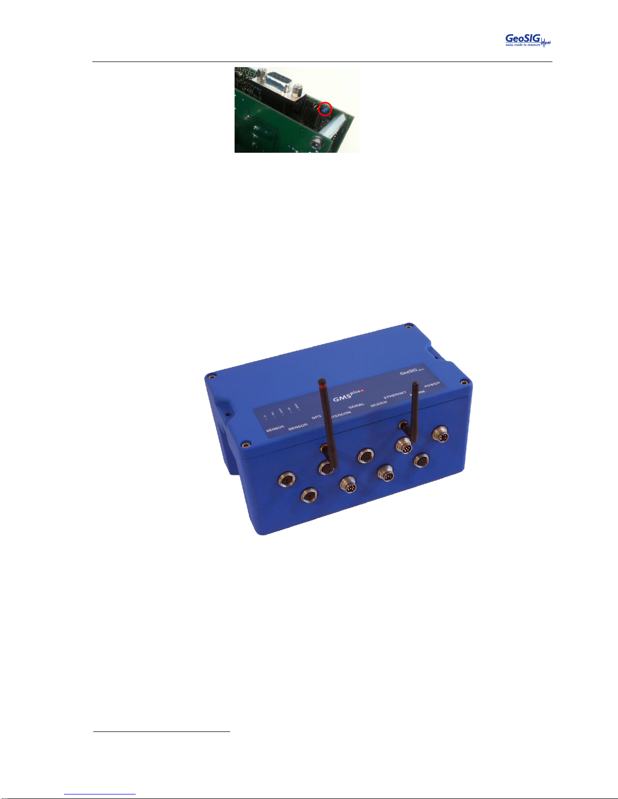
Autonomy of Real Time Clock on its backup battery is typically three years at ambient temperature. The
jumper JMP_BBATT on the main board has to be put in position 2-3 to disconnect this backup battery. This
must be done by a trained person only as a removal of the black cover is required.
Page 15
GMSplus User Manual
20.06.2017 / V21 15 / 124
GS_GMSplus_UserManual_V21
Figure 1. Position of JMP_BBATT
4. Description
4.1. Housing
The instrument is a housing mounted with a base plate. The base plate is fixed on ground and levelled one
time during installation, then the instrument can be replaced without need for levelling.
Figure 2. Instrument housing1
4.2. The housing lid
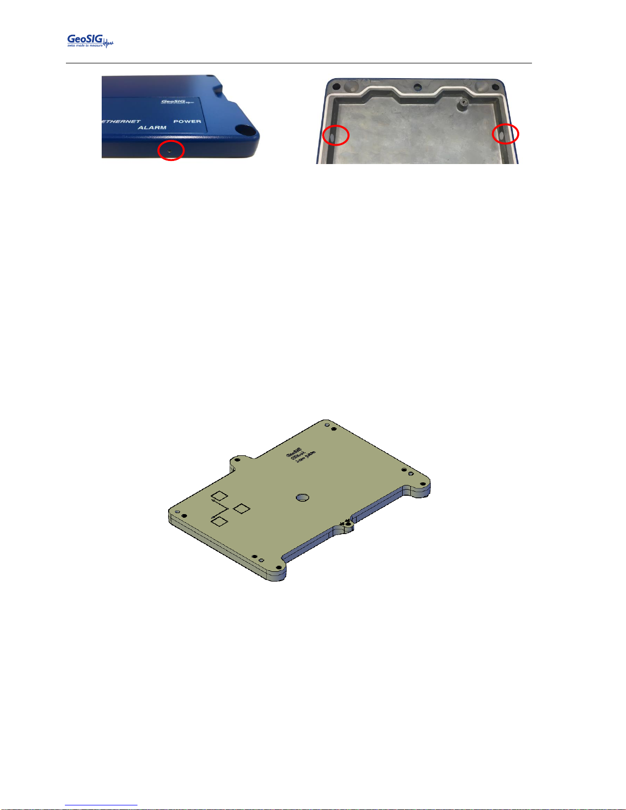
If your instrument has been supplied with an internal Lead Acid battery (main battery), the housing lid will
have two ventilation holes that are covered by special membrane vents, as shown in Figure 3. A Lead Acid
battery as a matter of course will release small amounts of hydrogen which may cause an explosion under
certain conditions. A typical GMSplus housing will allow hydrogen to escape through various small openings
in the housing, however as an extra level of safety, precautionary measures have been taken by providing
two ventilation holes to allow additional air circulation within the housing. The specially applied membrane
vents will prevent external matter from entering the housing while allowing air circulation through specially
designed PolyVent membranes as shown.
1
Connectors may vary depending on ordered configuration
Page 16
GMSplus User Manual
16 / 124 20.06.2017 / V21
GS_GMSplus_UserManual_V21
Outside view
Inside view
Figure 3. Housing lid ventilation holes
Please ensure that the vents are not covered and that the instrument is not placed in a confined area without
adequate ventilation. GeoSIG will not accept any responsibility for the safe operation of the battery or any
safety related consequences that may result from using the battery.
Please consult GeoSIG in writing if you have any specific questions or require clarification with regards to
use of the battery in the instrument.
4.3. Base plate
A base plate is supplied with the instrument for fixation and levelling of instrument on site. Three levelling
feet are provided to adjust horizontally the base plate. The fixation is done as a single point in the middle of
the plate.
To ensure correct orientation when an instrument is installed on the plate, two pins are provided with the
plate. They can be mounted in different positions according to the orientation required and will fit in the two
holes existing in the base of the instrument.
A connection point for earthing is also provided with the plate as a M6 thread.
Figure 4. Instrument base plate
4.4. Connectors
The instrument has up to nine connectors and two antenna plugs:
Page 17

GMSplus User Manual
20.06.2017 / V21 17 / 124
GS_GMSplus_UserManual_V21
Figure 5. Instrument with all connectors. Antennas are not mounted.2
4.4.1. Standard External Connectors
These connectors always will be assembled:
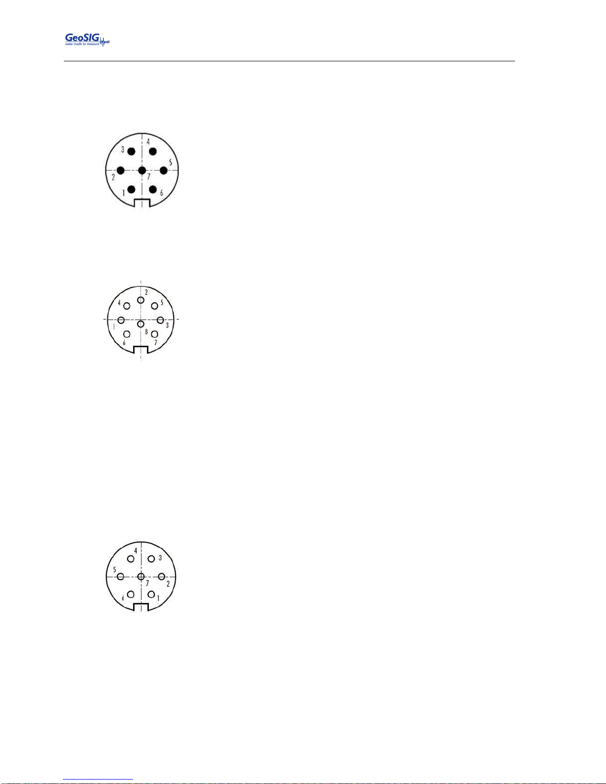
POWER Connection to the power supply module of the instrument or to an external battery.
LAN Connection with Ethernet cable to a LAN. The cable connection is dominant over the Wi-Fi
link. As soon as the cable connector is plugged in the instrument LAN socket, the Wi-Fi
module will be turned off, even if the RJ45 connector at the end of the cable is not plugged
into any socket.
SERIAL Connection to the console or for the serial data stream output, depending on the cable type.
Optionally also the cellular modem can be connected to this port.
GPS For connection to a GPS receiver.
4.4.1.1. POWER Connector
2
Connectors may vary depending on ordered configuration
3
Cannot be used together with an internal battery
Pin
Description
1
External power supply, 15 VDC
2
GND
3
External battery3, 12 VDC
4
GND
5
Shield
POWER
GPS
LAN
Wi-Fi
SERIAL
WiSync
INTERCON
MODEM
ALARM
SENSOR 2
SENSOR 1
Page 18
GMSplus User Manual
18 / 124 20.06.2017 / V21
GS_GMSplus_UserManual_V21
Mating Type: Binder Series 423, cable connector female, 5 pole
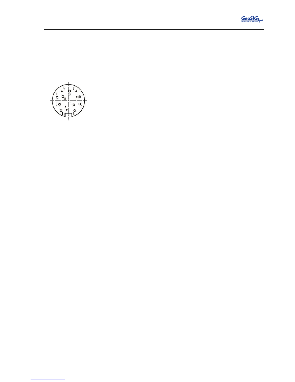
4.4.1.2. ETHERNET Connector
Mating Type: Binder Series 423, cable connector female, 7 pole
4.4.1.3. SERIAL Connector
Mating Type: Binder Series 423, cable connector male, 8 pole
4.4.1.4. GPS Connector
Mating Type: Binder Series 423, cable connector male, 7 pole
4.4.2. Optional External Connectors
These connectors depend on the ordered options:
SENSOR1 Connection to an external sensor.
SENSOR2 Connection to a second external sensor in case of a six channel instrument with two external
sensors.
Pin
Description
1
Detection if cable is connected, to be connected to GND inside the cable
2
RXD+
3
RXD-
4
TXD+
5
TXD-
6
Shield / GND
7
Shield / GND
Pin
Description – COM Pinout
1
TXDa
COMa: ttyS2 or ttyS3
2
RXDa
Serial data streaming and cellular modem
3
RTSa
4 CTSa
5
TXDb
COMb: ttyS0
6
RXDb
Configuration Console
7
Power, 12 VDC
For external cellular modem only
8
GND
Pin
Description – USB Pinout
1
USB Device Vbus
USB Device Connector
2
USB Device D+
3
USB Device D-
4
GND
5
USB Host D+
USB Host Connector
6
USB Host D-
7
USB Host Vbus
8
GND
Pin
Description
1
TXD
2
RXD
3
n/c
4
GND
5
1PPS
6
Power, 12 VDC
7
GND
Page 19
GMSplus User Manual
20.06.2017 / V21 19 / 124
GS_GMSplus_UserManual_V21
INTERCON Connection to the interconnection network allowing common time and common triggering.
MODEM Connection to analog phone line for the internal analog modem.
ALARM Contacts of the internal alarm relays
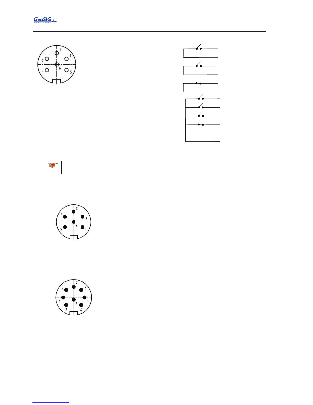
4.4.2.1. SENSOR Connectors
Mating Type: Binder Series 423, cable connector male, 12 pole
Pin
Description
A
X+
B
X- C Y+ D Y- E Z+
F
Z-
G
S_Test, Calibration Test Pulse
H
GND
J
Power, 12 VDC
K
GND
L
S_Mode, Calibration Enable
M
Analog AGND
Page 20
GMSplus User Manual
20 / 124 20.06.2017 / V21
GS_GMSplus_UserManual_V21
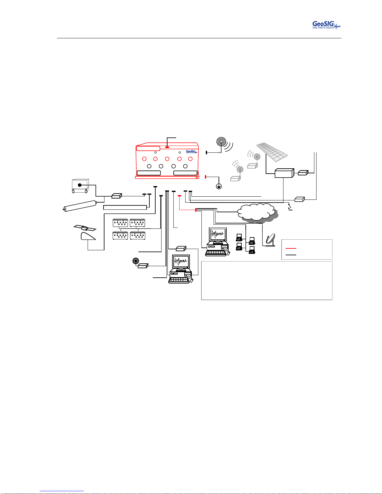
4.4.2.2. ALARM Connector
Standard Configuration
3 isolated relay contacts
Optional Configuration
4 relay contacts with
common pin
Mating Type: Binder Series 423, cable connector male, 6 pole
a
The contacts are suitable for a low voltage control. In case large load must be switched then
external relays must be implemented. Max rating of the internal relay is 125 V / 250 mA.
4.4.2.3. MODEM Connector
Mating Type: Binder Series 423, cable connector female, 6 pole
4.4.2.4. INTERCONNECTION Connector
Mating Type: Binder Series 423, cable connector female, 8 pole
Pin
Description
1
Line a
2
Line b
3
n/c
4
n/c
5
n/c 6 HGND
Pin
Description
Seismometer Control Option
1
Trigger +
/Lock
2
Trigger -
/Centre
3
Time Synchronisation +
Mass Position E/W
4
Time Synchronisation -
/Unlock
5
RS-485 + (not used)
Busy Signal
6
RS-485 - (not used)
GND
7
n/c
Mass Position N/S
8
GND
Mass Position V
Seismic 1
System Fault
Seismic 2
Seismic 3
Pin 1
Pin 2
Pin 3
Pin 4
Pin 5
Seismic 1
System Fault
Seismic 2
Pin 1
Pin 2
Pin 3
Pin 4
Pin 5
Pin 6
Page 21
GMSplus User Manual
20.06.2017 / V21 21 / 124
GS_GMSplus_UserManual_V21
4.4.3. Optional External Antennas
Wi-Fi Antenna connector for the wireless Internet
WiSync Antenna connector for 433 MHz synchronisation, allowing time synchronisation of several
instruments wirelessly.
4.4.4. Connectivity Options
A large variety of options can be connected to the instrument. The following figure should give an overview
of the main possibilities. Ask GeoSIG for details about any specific connectivity options.
Figure 6. Connectivity options
External
battery
12 VDC
SENSOR
SENSOR
GPS
SERIAL
ETHERNET
POWER
INTERCON
MODEM
ALARM
Legend
Standard supply
Optional supply 6
T+T line to
optional internal
landline modem
ALARM
Alarm Relays
ETHERNET
Desktop / Notebook
Local Area
Network (LAN)
VSAT
Internet
4G/3G/ADSL/etc
WiFi
Wi-Fi
Adhoc
Network
WLAN
GPS
GPS
SERIAL
L
RS-232 USB
Converter
External Service and
Configuration Port
3G/GPRS
INTERCON
Interconnected Network
PO
ETHE
SERGSEN
INTERMO433 WIPO
ETHE
SERGSEN
INTERMO433 WIPO
ETHE
SERGSEN
INTER
MO
433
WI
PO
ETHE
SERGSEN
INTER
MO
433
WI
RS-422 & RS-485 for
devices such as
Windsensor, etc
SENSOR
2
External Sensor 2 / Optional JB
SENSOR
1
Optional JB 3
Downhole-Sensor 1
1. Sensor(s) can be 1, 2 or 3 channels (triaxial, biaxial, uniaxial)
2. Available only with 6 channel units (GMSplus6), optionally up to four AC-7xd digital sensors can be
connected on the second SENSOR connector enabling the GMSplus to have totally up to 15 sensor
channels
3. JB combines 1 or 2 channel sensors or is used for long cables (depending on the power source and the
sensor)
4. The baseplate includes mounting and levelling screws as well as a concrete anchor
5. GMSplus series is a highly advanced unit with many options such as portability set, seismometer
control, external on/off button, transport case etc, not shown here, please contact GeoSIG for further
information
6. Optional supply and connections may require third party devices and/or services which may not typically
be provided by GeoSIG. Not all options can be used together
Internal Sensor 1
Internal Battery
Baseplate 4
P.E
Desktop / Notebook
RJ45
3 chn
upto 12 chn 2
External Sensor 1
POWER
AC Power
100 / 240 VAC
Solar Panel
Charging
Adapter
8 GB SD Card
open end
5 m
Power
Block
Internal Service
and Configuration
SERIAL
Page 22
GMSplus User Manual
22 / 124 20.06.2017 / V21
GS_GMSplus_UserManual_V21
4.4.5. Internal Connector
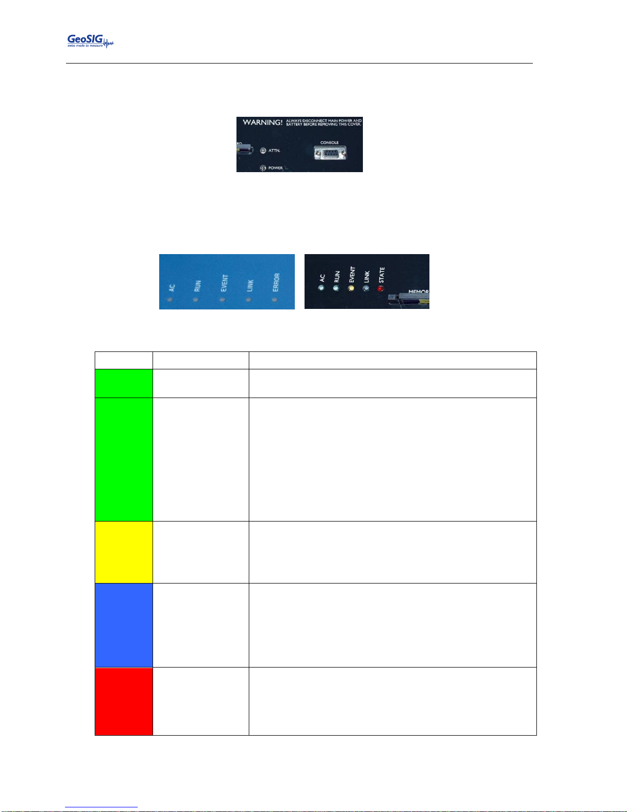
The instrument is equipped with an internal RS-232 connector giving access to the console. A standard RS232 extension cable (straight, female-male) can be used to connect to a computer
Figure 7. Internal RS-232 connector for the console
4.5. Visual Indicators
Several visual indicators (LEDs) show the status of the instrument.
Figure 8. Visual indicators on the cover (left) and inside the instrument (right)
Indicators, from left to right:
Colour
Indication
States
GREEN
AC
indicator
When ON, the external power supply is present
GREEN
RUN
indicator
OFF: the unit is off
Blinking 20% ON, 80% OFF at 2 sec period: The instrument is
starting up or the data acquisition program has been stopped or
is not running
Blinking 20% ON, 80% OFF at 1 sec period: Normal operation
of the instrument, data acquisition is running
Blinking 80% ON, 20% OFF at 2 sec period: Instrument is
shutting down, data acquisition is not running and the instrument
will be powered down soon
YELLOW
EVENT
indicator
OFF: Unit is not recording and no events are on the CF card
Blinking: Indicates the amount of memory used on the CF card
(<25%, >25%, >50%, >75%)
ON: The unit is recording
BLUE
LINK
indicator
OFF: Link with the data server is established, no communication
ongoing
Blinking at 1 sec period: Problem with the link to the data
server
ON: Link with the data server is established, communication or
data transfer ongoing
RED
ERROR / STATE
indicator
OFF: No problem or warning
Blinking at 2 sec period: Warning is present
Blinking 1 sec period: Error is present
ON: Data acquisition is not running, e.g. during start up
Table 2. Indicators description
Page 23
GMSplus User Manual
20.06.2017 / V21 23 / 124
GS_GMSplus_UserManual_V21
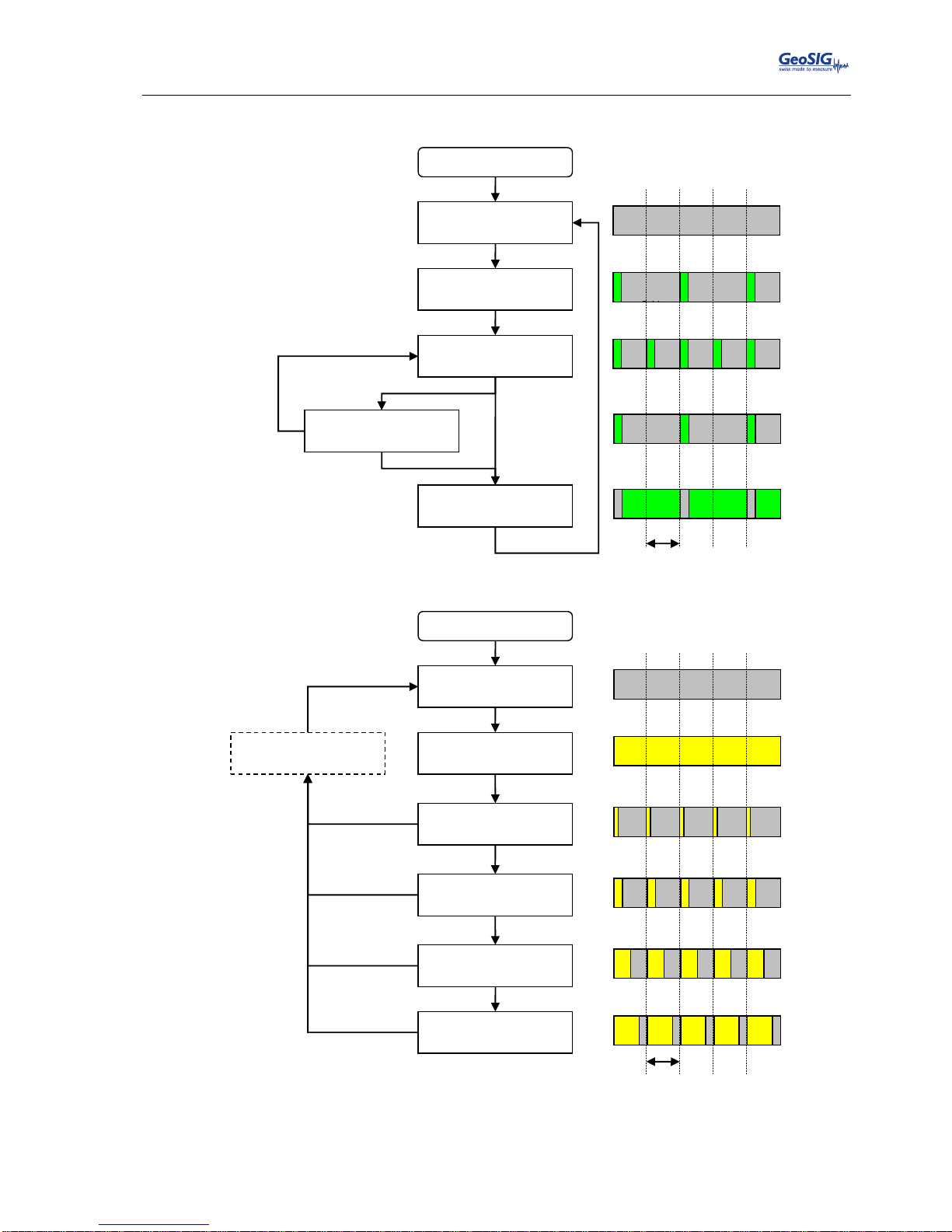
4.5.1. Detail Description
Figure 9. RUN indicator
Figure 10. EVENT indicator
Normal operation of
main program
Instrument is starting up
RUN
Instrument is shutting down
1s
OFF
Unit is OFF
Main program is stopped
EVENT
Instrument is
recording
Memory used
>25% and < 50%
Memory used
>50% and < 75%
Memory used
>75%
OFF
ON
No event stored in
CF and not recording.
At least one event recorded
and memory used <25%
Erase files from
memory card
1s
Page 24
GMSplus User Manual
24 / 124 20.06.2017 / V21
GS_GMSplus_UserManual_V21
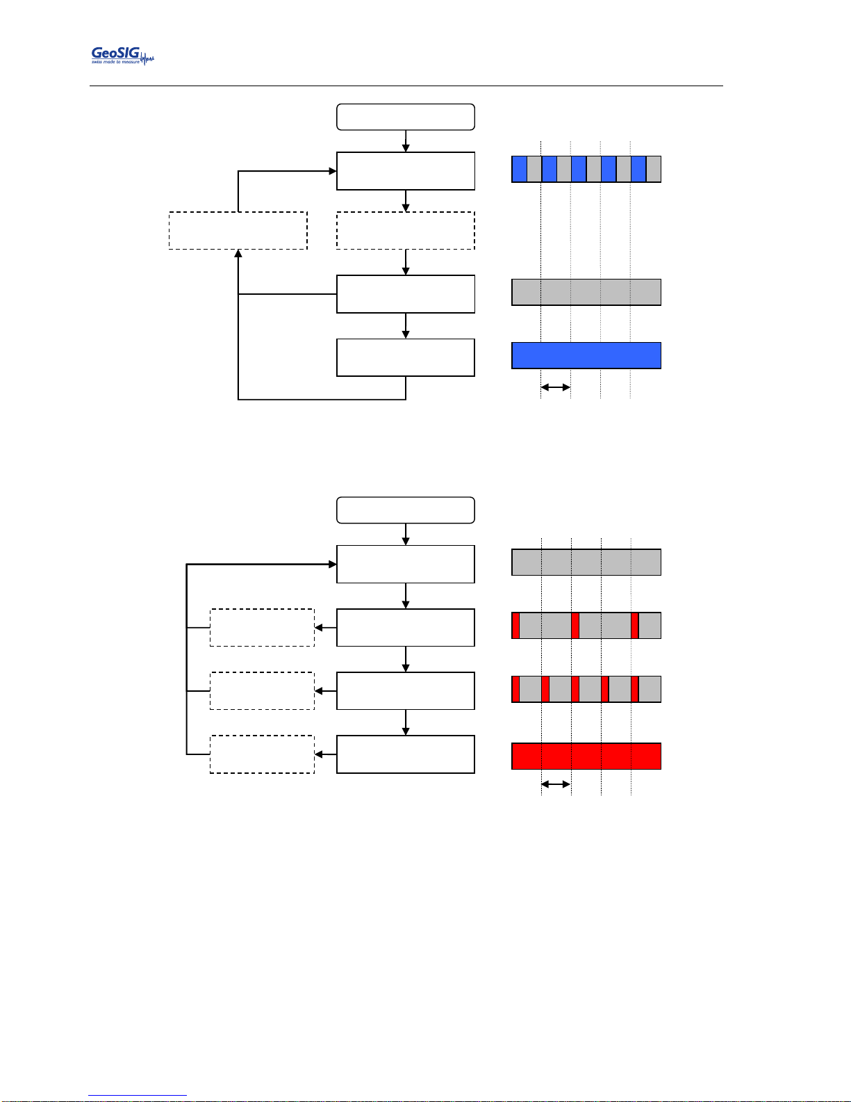
Figure 11. LINK indicator
Figure 12. ERROR indicator
LINK
Instrument is connecting to
the data server
Link to data server OK,
communication ongoing
No link to the data server
Link to data server OK, no
communication
OFF
Connection to data server
interrupted
1s
ON
ERROR
1s
OFF
ON
No warning or error
Clear errors and
warnings
Warning is present
Error is present
Data acquisition is
not running
Clear errors and
warnings
Launch
armDAS
Page 25
GMSplus User Manual
20.06.2017 / V21 25 / 124
GS_GMSplus_UserManual_V21
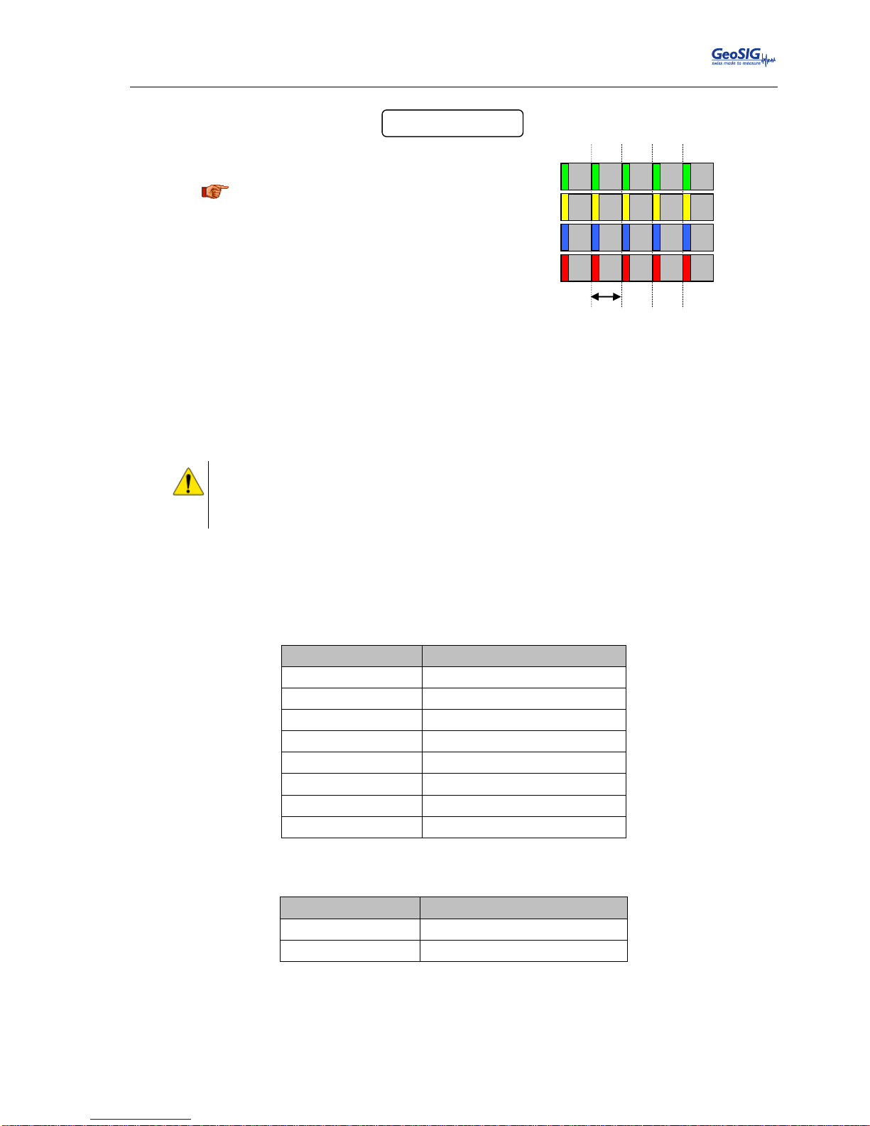
Figure 13. File checkup
4.6. Internal Batteries
4.6.1. Main Battery
a
The safety instructions given in “BATTERY (MAINTENANCE) AND SAFETY” as well as
chapter 3.1 must be strictly followed.
Following the safety instructions helps to reduce risk of fire, electric shock, personal injury and
material damage.
If installed, the battery is used in the instrument to power it in case of external power loss. If the external
power is not restored when the battery reaches a low level, the unit will switch off by itself to avoid deep
discharge of the battery. This protects the battery against capacity reduction or destruction occurring usually
in case of deep discharge for such battery type. The battery has the following specifications:
Description
Specification
Nominal Voltage
12 V
Capacity
7.2 Ah
Length
153 mm
Width
66 mm
Height
96 mm
Overall height
102 mm
Weight
2.65 kg
Connection
Faston 6.3
Table 3. Main battery specification
The following models have been checked to be compatible with the instrument:
Supplier
Model
FIAMM
FG20721
Yuasa
NP7-12
Table 4. Main battery models
File Checkup
1s
At startup, three LEDs (yellow, blue and
red) may flash synchronously for some
while, which indicates that firmware is
performing the full check of all files stored
on the compact flash card. The process
may take longer if there are many files
collected.
Page 26
GMSplus User Manual
26 / 124 20.06.2017 / V21
GS_GMSplus_UserManual_V21
4.6.2. Backup battery
The backup battery is used to maintain time in the instrument when it is powered off. It requires the following
specifications:
Description
Specification
Nominal Voltage
3 V
Capacity
285 mAh / 270 mAh
Cell diameter
24.5 mm
Cell height
3 mm
Weight
4.1 g
Table 5. Backup battery specification
The following models have been checked to be compatible with the instrument:
Supplier
Model
Renata
CR2430 MFR
Duracell
CR2430
EEMB
CR2430
Table 6. Backup battery models
4.7. Power Supply
4.7.1. Choice of Power Supply
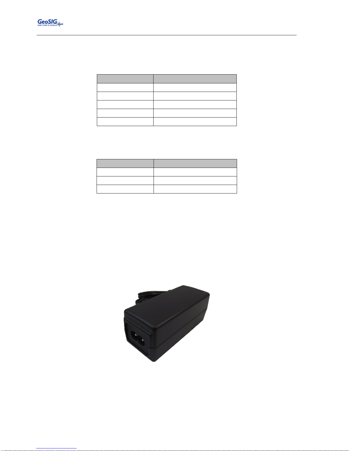
The main power should be provided to the instrument from a 15V DC source. The optional AC/DC power
module provides 15 VDC at 1A unless otherwise specified. The AC entry is compatible with 110 / 60 Hz or
230 / 50 Hz network without any adjustment. The block has a C7 connector and can use any standard power
cord with such connector. The power module and the power cord supplied are both CE and UL approved.
The power module must be connected to AC with a 2-wire power cable providing Phase and Neutral.
Figure 14. Power supply
Optionally the instrument can be built to have a 9 to 36 VDC power input range. This option must be
specified at order time.
4.7.2. Automatic Power On and Off
The instrument has a defined minimum start-up voltage of 12.5 VDC and will automatically make a controlled
power down if the supply voltage goes below 10.6V DC.
Page 27

GMSplus User Manual
20.06.2017 / V21 27 / 124
GS_GMSplus_UserManual_V21
4.8. Supplied and Optional Accessories
4.8.1. Standard Supplied Accessories
The following parts will be included in a shipment additional to the instrument:
Fixation baseplate with levelling feet
Screw and anchor bolt for fixation
Ethernet cable, category 5 cable for 10/100 Mbit network with a suitable connector for the
instrument, 5 meters of cable and a standard RJ45 connector. Other cable lengths are available by
request.
4.8.2. Optional Accessories
The following parts can be ordered additionally and will be added if specified at order time:
External power supply module, 100 to 230 VAC / 50-60 Hz, CE and UL approved
AC power cable, depending on the shipping address with European, US or Swiss power plug
GPS time code receiver with 20 meter cable, other cable length on request. GPS is an option as
the time can also be synchronised through the network using NTP
Console cable for use on the external SERIAL connector
Data stream cable for use on the external SERIAL connector
SD/CF card reader for USB for reading the memory card on a computer or laptop
Cellular modem
Any spare connectors
Any spare antennas
Spare battery
Page 28

GMSplus User Manual
28 / 124 20.06.2017 / V21
GS_GMSplus_UserManual_V21
5. Installation
This section lists the procedures involved in installation of the Instrument. The procedures will be outlined as
steps to be performed in the field or in-house prior to deploying the instrument in the field.
5.1. Site Selection
5.1.1. Environmental Considerations
The choice of an installation site for a seismic event recorder is similar in most respects to that of a regular
continuous recording seismic station.
Although the instrument is housed in a solid, weatherproof case, it should be installed in a place free from
direct sunlight, precipitation, the danger of falling materials in the event of a severe earthquake and the risk
of tampering or vandalism if the unit is to be left unattended.
There are also special considerations for event recorder installations. It is important to select the site and set
the trigger level to avoid unwanted data recording, such as vibration from machinery, highway traffic, aircraft,
waves, etc. It is wise to check the instrument frequently during the first several days of operation after each
set-up, to see if there are previously unsuspected sources of noise which are triggering the instrument and
using up the memory.
In addition, the user should select a site with a provision for 115 / 230 VAC power if the unit will be left in
place for a long period of time (more than 26 hours). Although this is not necessary for the operation of the
device, it does preclude concerns about battery charging.
You should make note at this point of any cultural or environmental sources of noise and vibration around
the selected site, which may cause false triggers of the recording mechanism. These will have to be
considered when setting the trigger parameters.
The operating temperature of the instrument itself is -20°C to +70°C. Nevertheless, if any additional internal
or external accessories/modules (e.g. batteries, sensors, modems, etc) with lower operating temperature
ranges are used, the operating temperature of the combined system will be then limited by the temperature
characteristics of these accessories/modules.
5.1.2. Power Supply Considerations
The instrument may be powered from a 115 / 230 VAC supply through an external AC/DC converter, from an
internal or external battery, or optionally from a 15 VDC external supply such as an automotive battery or
solar panels. It can also be powered from an external DC power supply from 9 to 36 VDC (any of these
options must be specified at order time).
If the supply in the field will be from a 115 / 230 VAC supply, you need to connect the VAC cable
from the external AC/DC to the power source only. The instrument operates continuously, providing
a trickle charge to the internal battery, if supplied. The VAC supply must consist of Phase and
Neutral.
If the supply in the field will be from a 9 to 36 VDC supply (optional), you need to connect the
power cable from instrument to the power source only. The instrument operates continuously,
providing a trickle charge to the internal battery, if supplied.
If the instrument is running from an external battery (optional), you need to connect the delivered
battery cable from Instrument to the power source only. In this case there should be no internal
battery installed. The external battery must be charged with an external battery charger.
If the supply will be exclusively from the instrument’s internal battery, it is necessary to charge the
battery sufficiently beforehand. Make sure to have at least 24 hours of uninterrupted charging prior
to leaving the Instrument in the field. The configuration of the instrument, of course, may be
performed while the charger is connected to the instrument. The external AC/DC converter has to
be plugged to 115 / 230 VAC for charging the internal battery.
The best approach to the deployment of the instrument is to use an internal battery along with the VAC/VDC
power at the remote site. It is highly recommended to check and configure the instrument for the correct
time, trigger and other relevant settings in the lab, prior to the installation (see chapter 7). It may then be
carried to the remote site (it should be switched OFF to conserve the internal battery) and then connected to
Page 29
GMSplus User Manual
20.06.2017 / V21 29 / 124
GS_GMSplus_UserManual_V21
the VAC power through the external AC/DC converter or directly to the VDC power supply. After turning the
instrument ON (see chapter 10.1), the instrument runs with the pre-configured parameters. This reduces the
amount of time needed to configure in the field -- an important consideration in the case of an adverse
condition.
5.1.3. Communication Considerations
An Ethernet connection or Wi-Fi signal must be present to have a data communication. If the instrument
uses an NTP Server as time source, please make sure that an internet connection is available and the
network settings are properly set in the instrument. Optionally an external cellular modem can be used for
the connection to the internet. Use of NTP is not recommended when using a cellular modem; a GPS should
be used instead if possible.
If the instrument is used as a standalone recording station, a notebook with an Ethernet connector can be
used for downloading the data on a regular basis. In a network the stations will upload the data to the
configured server.
5.2. Installation
a
For your convenience a training video explaining the installation of the GMS-xx and GMS
plus
is
available at www.geosig.com Support ‘How To …’ Videos
a
Many times the locations of seismic equipment are highly exposed to electrical disturbances
caused by lightning or by the industrial environment. Although the instrument contains over
voltage protection, it may sometimes be necessary to use additional surge protectors for the
equipment. Contact GeoSIG or your local representative for more information.
a
Typically it is required to connect the baseplate to the local earth to avoid or minimise 50/60 Hz
distortions in the signal by surrounding power lines. Use the provided M6 earth screw and
make sure to have a proper connection by using only short cables with large diameters.
5.2.1. Requirements for the Instrument Foundation
Minimum surface area requirements
with internal sensor: 30 x 26 cm
with external sensor (excluding area of sensor itself): 30 x 30 cm
a
Foundation has to be very well anchored or adhered preferably to a rock or concrete base. In
case of a need for a foundation on soil, a concrete cubicle of 1 m3 has to be cast in the ground
to serve as a base.
5.2.2. Mounting the Instrument
The unit must be fixed rigidly on the building foundation; it has a base plate that must be first fixed on the
ground and then the instrument mounted on it. For that purpose, the base plate has a central fixation hole
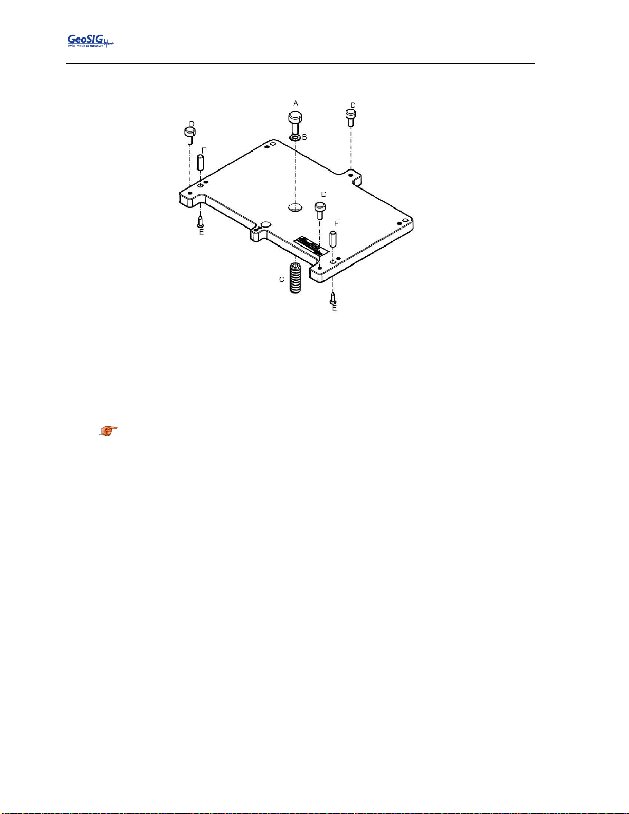
(suitable for 8 mm screws) and three levelling screws. Prepare the base plate (see also Figure 15):
Mount the three levelling screws (D).
Check that the 4 M6 threads for the instrument fixation are free from dust.
Mount the two polarization pins on the base plate on the side where the connectors will be (E/F).
Place the base plate at the selected location. Verify that the surface is sufficiently flat and horizontal so that
the three feet can level the plate. Be sure to leave enough space at the front of the Instrument for the
connectors and for opening the cover. The sides of the instrument should typically not be closer than 100
mm (4“) from a wall. Mark on the ground the location of the central hole in the plate. Remove the base plate.
The instrument itself can be mounted in any orientation desired under the condition that it does not have an
internal battery. In cases where the instrument has an internal battery it must always be mounted flat on the
Page 30
GMSplus User Manual
30 / 124 20.06.2017 / V21
GS_GMSplus_UserManual_V21
ground in a non-tilted position. If the installation requires both a battery and a tilted, wall- or ceiling-mounted
instrument, the battery must be placed externally.
Figure 15. Installation of the base plate
Drill an 11 mm hole in the concrete with a typical depth of 50 mm for the supplied M8 concrete anchor (C). If
another model is used, please adapt the hole dimensions accordingly. Clean the hole area of the dust. Insert
the concrete anchor into the hole. Mount the plate in place and insert the M8 fixation screw (A/B) in its hole.
Turn the plate so it is oriented according to requirement. Make a coarse levelling of the plate (D). Start fixing
the plate by tightening the M8 central screw (A). Check regularly the plate orientation and level till the plate is
rigidly fixed (D). Remove the cover of the instrument and put it on the mounting plate using the four screws
and washers to fix it. Keep care about the two orientation pins on the plate (E/F).
a
Do not over tighten the levelling screws.
Do not cause any short circuit on the battery poles or inside the unit.
Connect the base plate to the local protection earth.
5.2.3. Orientation, Levelling and Calibration of the Sensor
Check it is really fixed by pushing from all directions. If you feel any movement, recheck the fixation.
Internal Sensor: The sensor is located under the internal cover; as no setup is required for the sensor, there
is no need to remove the internal cover. The levelling is done on the base plate, and the sensor is already
configured to operate with the recorder.
Nevertheless for most applications it is important that the internal sensor is aligned according to the
requirements. This can be done using the axes label on the wall of the instrument. In case the axes shall be
aligned according to the global coordinate system, the Y-axis must point direction north. So X corresponds
then to E-W, Y to N-S and Z to U-D.
External Sensor: Mount and level the sensor according to its manual and connect to the external sensor of
the instrument. There is no need to align the instrument to a certain direction.
5.2.4. Supply Voltage
The instrument should be powered from 110 VAC up to 240 VAC, 50 or 60 Hz through an external AC/DC
converter or any other option described in chapter 5.1.2.
Optionally the instrument can be directly powered by an external battery or a 24 VDC or 48 VDC line. Please
contact GeoSIG for more details.
5.2.5. Installing other Components, Options, Accessories
For installation of other components options or accessories please refer to the specified option manual.
Page 31

GMSplus User Manual
20.06.2017 / V21 31 / 124
GS_GMSplus_UserManual_V21
5.3. First Start and Communication Setup
With the instrument correctly fixed on the ground through the fixation plate please proceed with chapter 7 for
the first start-up and configuration.
Page 32
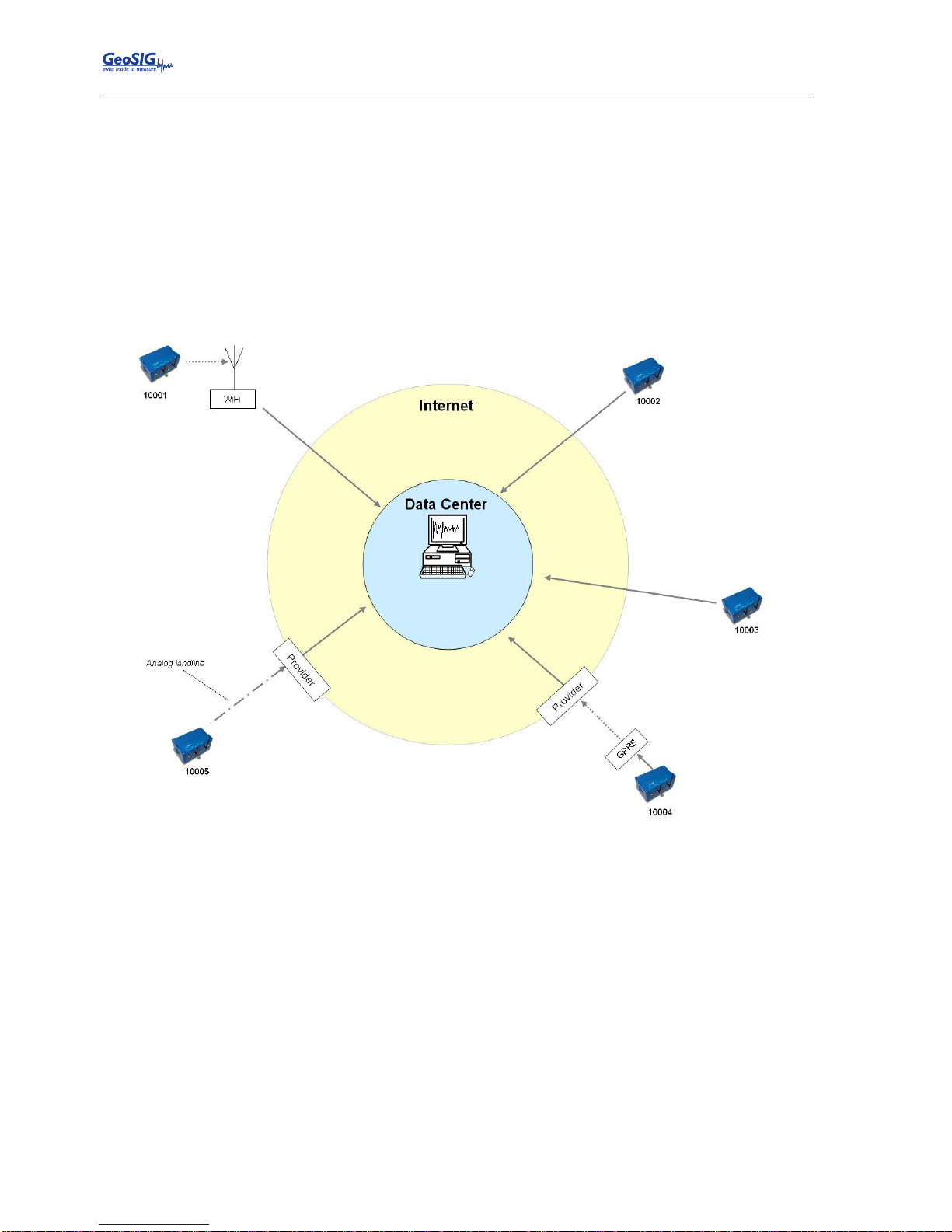
GMSplus User Manual
32 / 124 20.06.2017 / V21
GS_GMSplus_UserManual_V21
6. Principle of Operation of the Instrument
This chapter gives an overview about the normal operation of the instrument in a network or as a standalone
unit.
6.1. Normal Operation
During normal operation the instruments are installed on sites and connected to a data server over Ethernet
or Internet. The instrument checks in a defined interval, if there are any requests or firmware updates ready
for pick up on the server. Additionally – and if configured – the instrument uploads the ringbuffer files (from
continuous recording) and the state of health files to the data server.
Figure 16. Normal operation in a network
6.2. Behaviour on a Seismic Event
In case there is an earthquake and the vibrations are above the trigger threshold, the instrument is recording
the event and immediately uploading it to the data server (see Figure 17).
In case some of the stations are too far away from the epicentre to trigger, the data can still be collected from
all instruments:
A data request will be placed on the server.
All instruments will download the request during the next time checking the server (see Figure 18).
Page 33
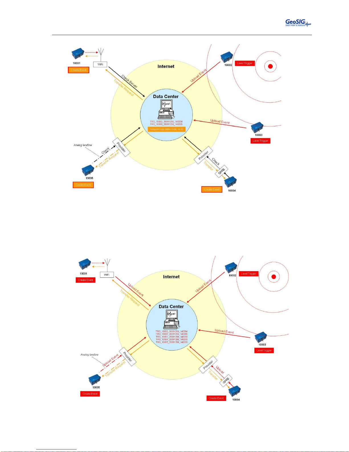
GMSplus User Manual
20.06.2017 / V21 33 / 124
GS_GMSplus_UserManual_V21
Figure 17. Upload of seismic events and download of requests from the server
All instruments will create an event at the time listed inside the data request and extract these data
out of the ringbuffer data.
The extracted event file will be uploaded to the data server (see Figure 18).
Figure 18. Behaviour on Events: Upload of extracted events
Page 34
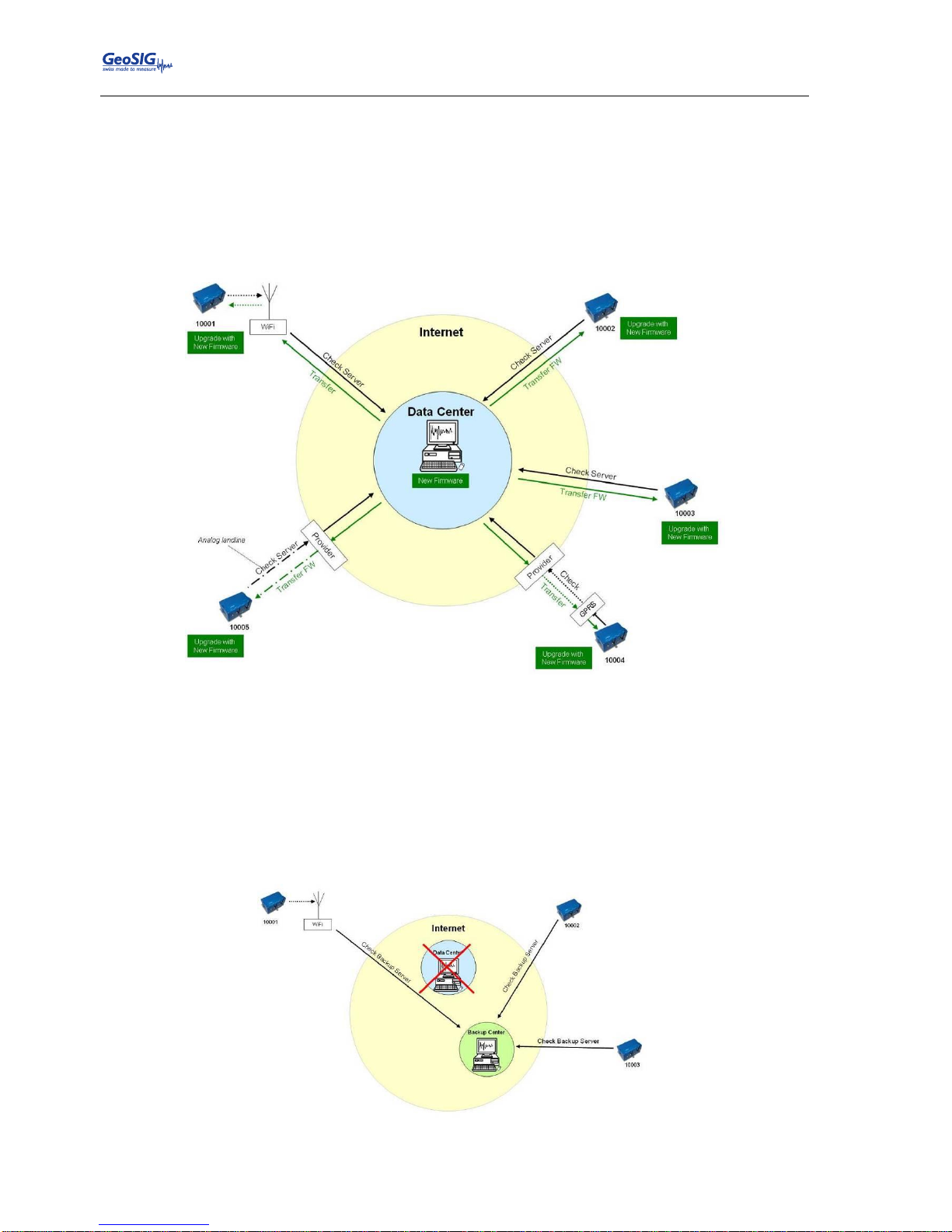
GMSplus User Manual
34 / 124 20.06.2017 / V21
GS_GMSplus_UserManual_V21
6.3. Firmware and Configuration Upgrade
In case of a firmware upgrade, the new firmware can be easily put on the server. All instruments will
recognise the new firmware during the next server check-up, download and install it. See chapter 12 for
details about the firmware upgrade.
The same happens also with new configurations. In case the option Keep connection to the server is
enabled under Server Parameters (see chapter 10.8 for details), then the instrument will keep the channel
open, so that it is possible to configure the instrument via the Web Interface without knowing the IP of the
instrument. See chapter 9 for details.
Figure 19. Firmware upgrade
6.4. Backup Server
It might be that the instrument is not able to contact the main data server anymore: Either because it is down
or a wrong server has been configured. For example, this can happen in case accidentally a configuration
file with wrong server settings will be uploaded to an instrument. In this case the instrument will contact the
backup server, configured in the test and configuration menu. Therefore the configuration of the backup
server is very important and should not be ignored. For more information how the set the backup server see
chapter 7.2.
Figure 20. Connection to backup server in case connection to main server fails
Page 35
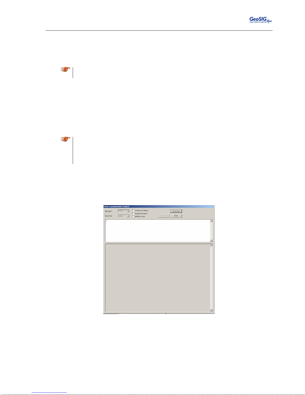
GMSplus User Manual
20.06.2017 / V21 35 / 124
GS_GMSplus_UserManual_V21
7. Quick Start Up
This chapter is intended to configure simple communication between the instrument and GeoDAS software
running on a Windows workstation, working as data server.
a
It is assumed that the GeoDAS software is already installed on a computer. If not, please do
the installation first with help of the GeoDAS User Manual before proceeding.
7.1. Preparation
Make sure the instrument is powered by the provided power supply. The green AC indicator should
be ON.
Make sure the instrument is connected to a LAN by the supplied Ethernet cable.
Remove instrument cover using the four screws on the top corners.
Verify that the battery is correctly fixed and connected to the system.
a
In case there is no LAN available, the Ethernet cable can be connected directly to a computer.
For this a crossed Ethernet cable is needed; please contact GeoSIG. Nevertheless in modern
computers normally it works as well with the supplied patch cable.
In any case the instrument and the computer must be configured to have a fixed IP. Please
follow the procedure to adjust these settings.
Connect the instrument to a serial port of your computer by using a standard RS-232 patch cable.
Open any terminal program and choose the appropriate COM port. Baud rate is 115200.
Alternatively open GeoDAS, go to Tools Terminal… and choose the COM Port. As Baud rate
select 115200. Then Press Connect
Figure 21. GeoDAS terminal
Keep the terminal open for the next step.
7.2. Set IP Address of the Instrument
Network settings of the Instrument can be changed during startup of the instrument. By default the
instrument has a dynamic IP.
Switch on the instrument by pressing and holding the POWER button for 2 seconds.
Page 36
GMSplus User Manual
36 / 124 20.06.2017 / V21
GS_GMSplus_UserManual_V21
Press <Ctr> + ‘Z’ as soon the following message appears on the console to enter the test mode.
GMSplus s/n 100582. Firmware in the Linux image: 21.11.00
#################################################
###### Test and Initial Configuration Mode ######
#################################################
Press Ctrl+Z to enter the test mode.....
The following menu will appear (see chapter 11 for details):
Press Ctrl+Z to enter the test mode................
Instrument serial number: 100582
Instrument MAC address: 00:50:C2:77:42:93
-------------------------------------------------------------------------------------------Level Shortcut Password Description
-------------------------------------------------------------------------------------------User Ctrl+U None Basic operations only
Powerful User Ctrl+W None Also hardware options and pre-selected tests
Administrator Ctrl+A None Also manual tests and altering the FLASH memory content
-------------------------------------------------------------------------------------------Your level [U/W/A] or press B to boot now:
By default no any passwords are set, so press ‘U’ to enter the User Mode, and then ‘N’ to enter the
menu Network settings.
==== Network Settings ====
---- Primary network interface ----
Configure network interface (Y/N)? Y
Static IP address (1=YES, 0=AUTO)? (0 = 0x0):
Select ‘Y’ to change the settings and then select if the instrument should have a static or a dynamic
IP by pressing ‘1’ (Static) or ‘0’ (dynamic). In case a dynamic IP is chosen, a DHCP server must be
available in the network to provide the IP settings.
In case a static IP is selected, an additional message will appear asking for the Instrument IP
address, Instrument network mask and Instrument gateway IP. In case you don’t know these
parameters please ask your network administrator.
In case the instrument has a Wi-Fi module, a second interface menu appears. Here static or
dynamic IP can be chosen and the available Wi-Fi networks can be scanned. Please see chapter
8.4 for details.
---- Wireless network interface ----
Configure network interface (Y/N)? Y
Static IP address (1=YES, 0=AUTO)?
In case the instrument is connected to the Internet via a PPP connection (cellular or analog
modem), then the APN and password must be configured. See chapter 10.8.3 for details.
---- PPP Communication ---Edit Analog Modem settings (Y/N)? Y
Phone number of the service provider [T313001]:
Login [demo]:
Password [demo]:
Updating configuration...
PPP settings have been updated
Edit Cell Modem settings (Y/N)? N
The instrument allows access to the operating system from remote over SSH. This feature is not
needed for the normal operation of the instrument and can be disabled in case of security
concerns. By default it should be kept enabled, to disable press ‘1’
---- Miscellaneous parameters ---Disable remote login over ssh (1=Yes, 0=Enable)? (0 = 0x0):
Page 37
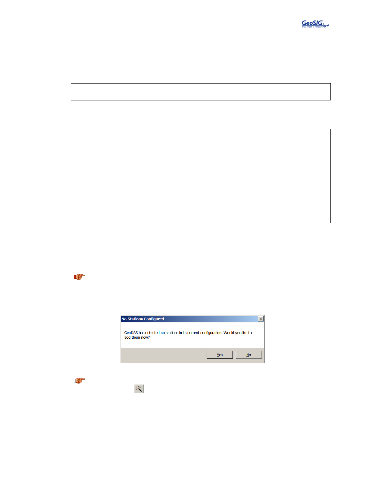
GMSplus User Manual
20.06.2017 / V21 37 / 124
GS_GMSplus_UserManual_V21
It’s highly recommended to put a recovery server IP address and recovery server port. The
instrument will contact this server every Recovery server contact interval in case the connection to
the main data server (configured in the configuration of the instrument) is not possible anymore.
This could happen, for example, if a configuration file with wrong server settings were accidentally
uploaded to an instrument.
Recovery server IP address (192.168.10.107):
Recovery server port (3456 = 0xD80):
Recovery server contact interval, hours (24 = 0x18):
As soon the following menu appears, press ‘5’ to start the instrument.
Bootloader Menu of the GMSplus s/n 100582
Access level: User
--- Flash Images and Boot Options --L - List flash images
Q - Reset instrument configuration to the user default
V - Reset instrument configuration to the factory default
5 - Boot now
X - Reboot the instrument
Y - Power off
--- Hardware Setup and Monitor --N - Network settings
--- Security --O - Set password
-->
As soon the instrument is running (red LED on the instrument goes off), start GeoDAS (if not
already done)
7.3. No Stations Configured at first Start Up
a
The following steps require GeoDAS version 2.24 or higher. If you have any older
version download the newest release from www.geosig.com Support Downloads
When GeoDAS is started for the first time, it will ask to add stations in its configuration.
Click Yes
Figure 22. “No stations configured” message at startup of GeoDAS
a
If there are already stations configured in GeoDAS, this window will not appear. Please press
the wizard button in the GeoDAS menu
Page 38
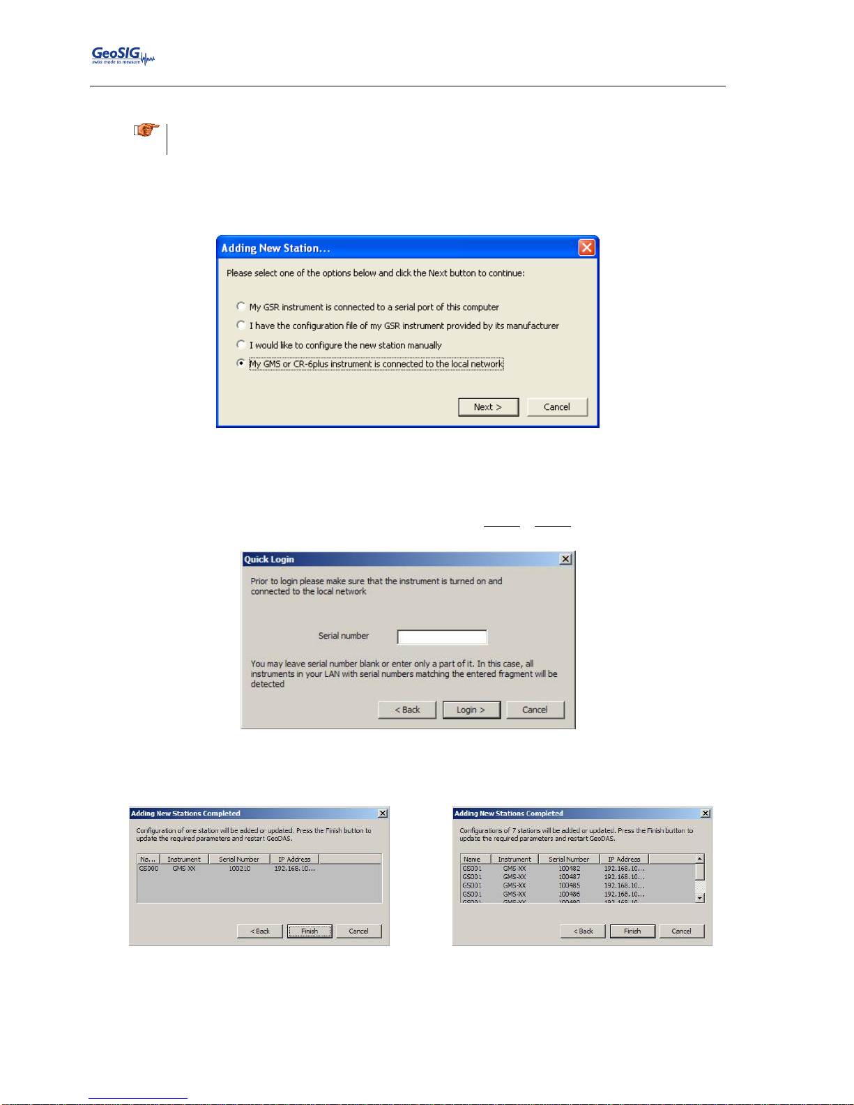
GMSplus User Manual
38 / 124 20.06.2017 / V21
GS_GMSplus_UserManual_V21
7.4. Adding New Stations…
a
Make sure the computer is connected to the same network as the instrument and in the same
IP range.
In the following window, select My GMS or CR-6plus instrument is connected to the local
network and press Next >
Figure 23. Instrument Wizard
Enter the Serial number of the instrument and press Login >. It is also possible to add more than
one station by entering only a fragment of the serial number which is similar on all instruments. For
example if there are the serial numbers 100210, 100211 and 100234. By entering ‘1002’ all the
stations will be added. By putting ‘10021’ just the stations 100210, 100211 will be added.
Figure 24. Quick Login Window
All the found stations will be listed, press Finish to add them to GeoDAS
Figure 25. List of all stations found – single station left, multi-selection right side
Page 39
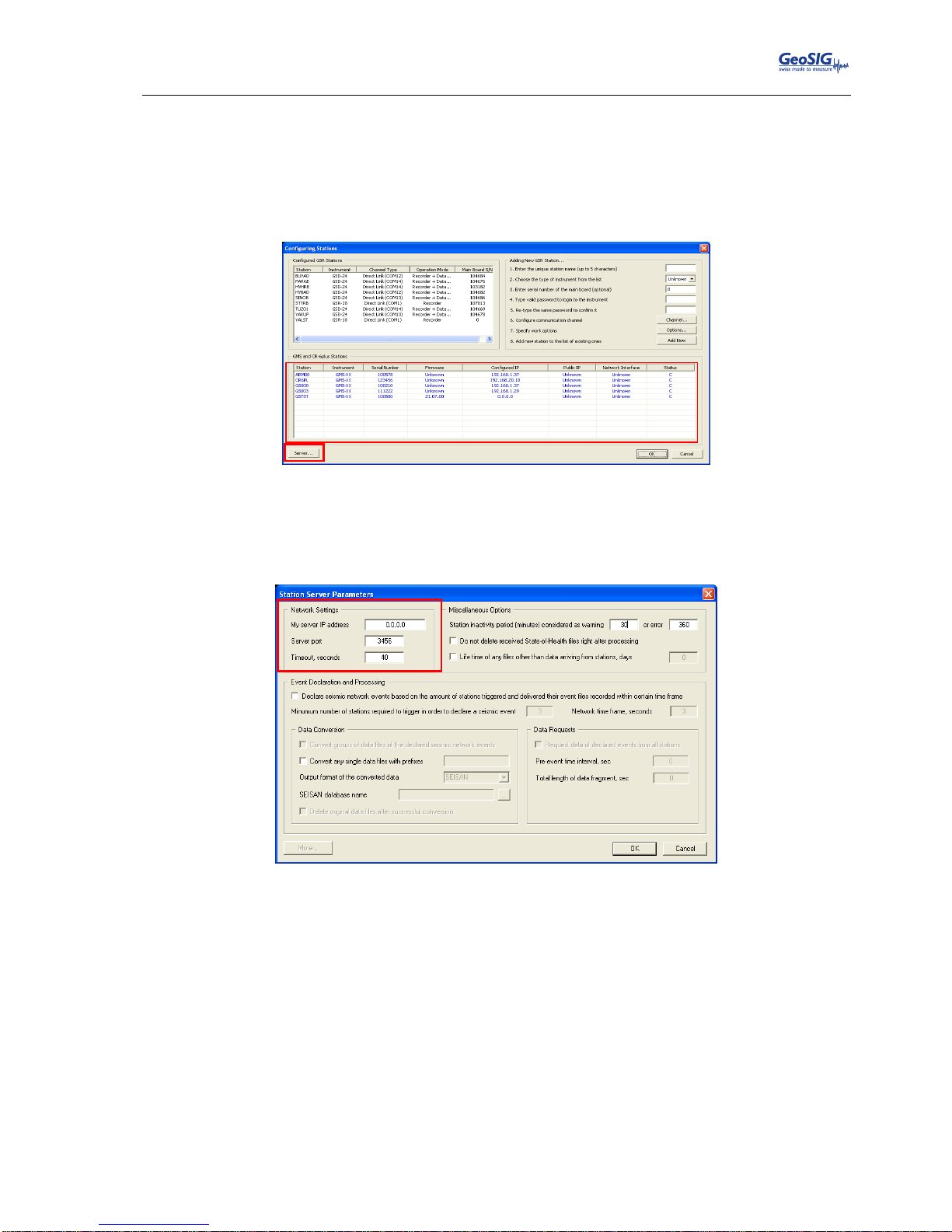
GMSplus User Manual
20.06.2017 / V21 39 / 124
GS_GMSplus_UserManual_V21
7.5. Configuration of Data Server
Proceed to the menu Settings Configure Stations…
The following window will appear where all the instruments are listed in the area 1. To add stations
make a right click and choose Add Station to current configuration. Please see chapter 14.1 for
details.
Figure 26. Configuration and overview of the stations
Press the button Server… When the window below appears, enter the following data:
▪ My server IP address IP of your computer
▪ Server port Select a user defined port, use 3456 by default
Figure 27. Data server parameter
1
Page 40
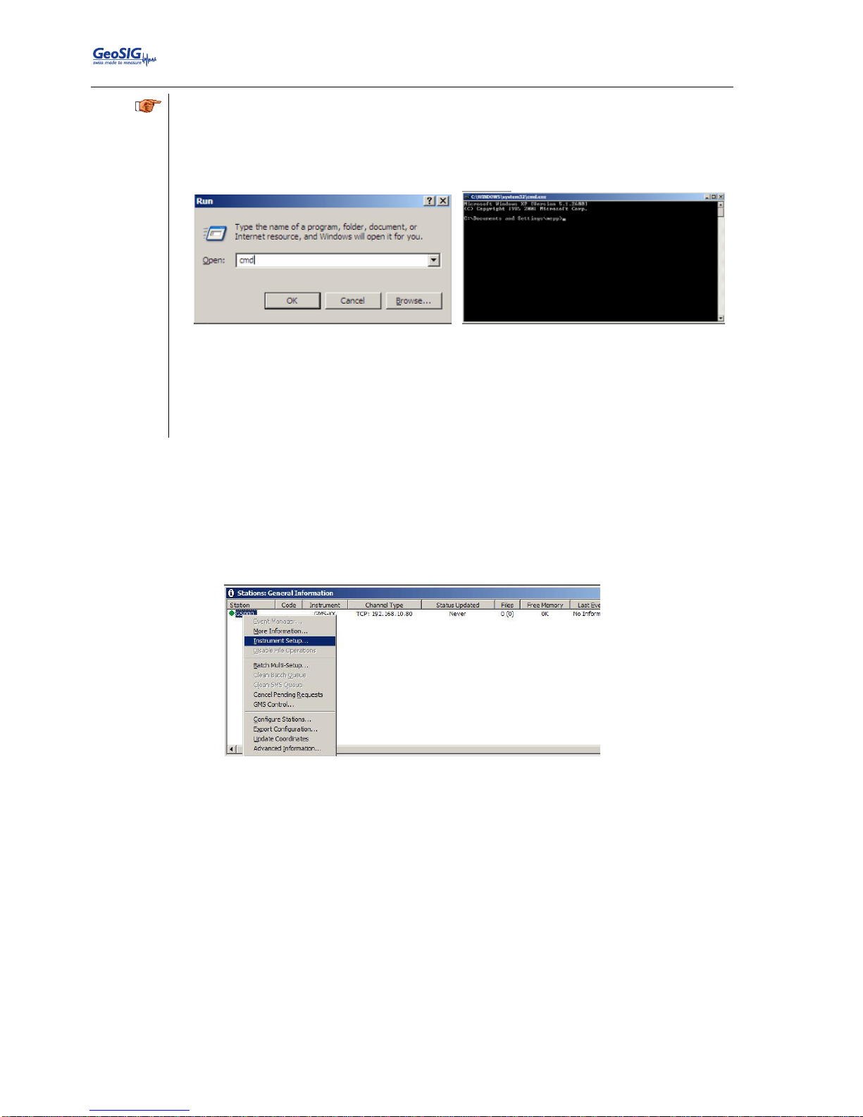
GMSplus User Manual
40 / 124 20.06.2017 / V21
GS_GMSplus_UserManual_V21
a
In most cases you do not need to enter an IP address. It may only be needed if your computer
has several network cards, and you would like to communicate to instruments connected only
to one subnetwork. Otherwise you may leave the default zero IP address 0.0.0.0
If you don’t know how to find out your IP address, follow these steps:
- Click Start Run type cmd, then press OK
- Type ipconfig, then your IP appears
Ethernet adapter Local Area Connection:
Connection-specific DNS Suffix . :
IP Address. . . . . . . . . . . . : 192.168.10.107
Subnet Mask . . . . . . . . . . . : 255.255.255.0
Default Gateway . . . . . . . . . : 192.168.10.254
- Type exit
Write down the IP and port you have configured
Press OK two times to exit again to the main window of GeoDAS
7.6. Basic Configuration of the Instrument
In the window Stations: General Information make a right click on the station name and select
Instrument Setup…
Figure 28. Instrument setup
A window showing the Web Interface will appear.
Page 41
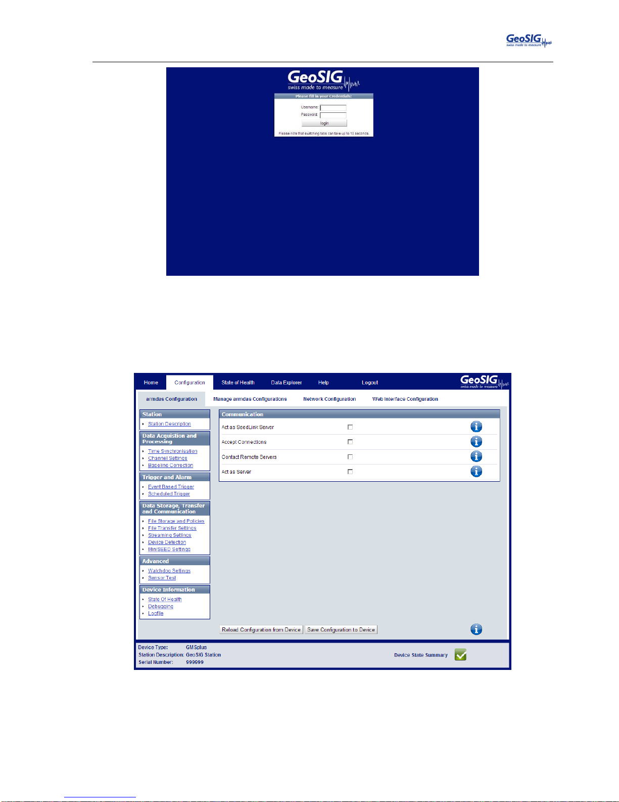
GMSplus User Manual
20.06.2017 / V21 41 / 124
GS_GMSplus_UserManual_V21
Figure 29. Web interface of the selected instrument
To be able to adjust the configuration of the instrument it is required to authenticate oneself to the
device. The default login credentials are: Username: admin, password: 123456. Then press login
Go to Configuration armdas Configuration File Transfer Settings, the following screen
appears.
Figure 30. Server parameters
Page 42
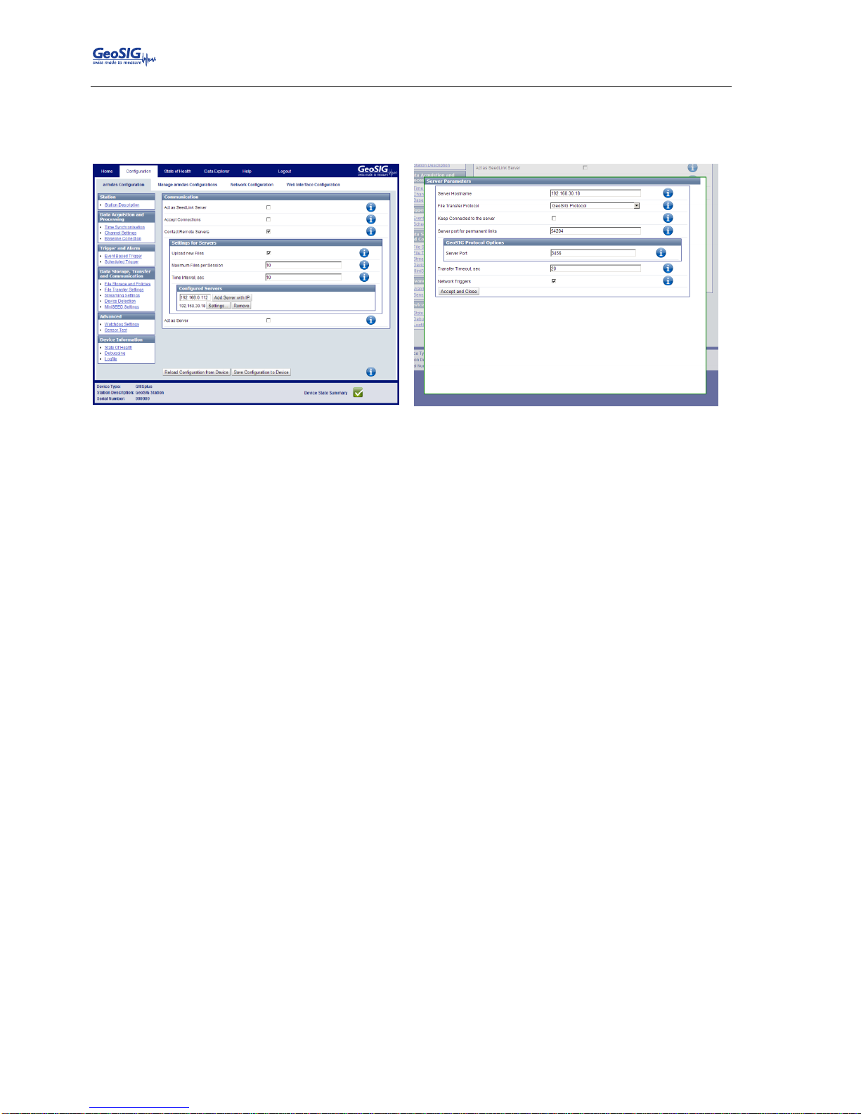
GMSplus User Manual
42 / 124 20.06.2017 / V21
GS_GMSplus_UserManual_V21
Tick the flag Contact Remote Servers to configure a connection to a remote server.
Add the IP of your server and press Add Server with IP. Under Settings… more options can be
configured. The default Server port is 3456 and should be kept.
Figure 31. Added Server (left) and its parameters (right)
Then press Save Configuration to Device.
After the instrument has restarted it is ready for operation and can be configured according to
chapters 9 and 10.
Page 43
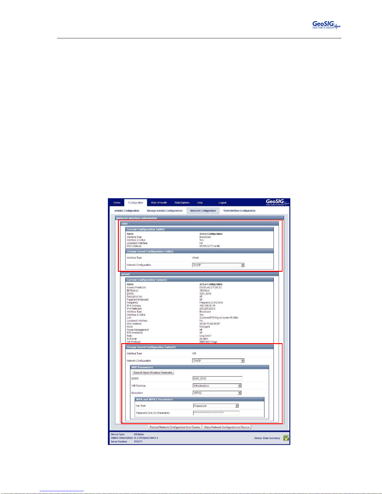
GMSplus User Manual
20.06.2017 / V21 43 / 124
GS_GMSplus_UserManual_V21
8. Network Settings
The network configuration is the same whether using a wired network or wireless network. The specific
settings related to the wireless network configuration via the local console are described in chapter 8.4.
8.1. Network Settings through the Web Interface or Instrument Setup…
To open the Web Interface please do one of the following two steps.
▪ In the window Stations: General Information of GeoDAS make a right click on the station name
and click on Instrument Setup … or
▪ Open your browser and enter the IP address of the instrument (see chapter 8.5 for details) in
the address bar of your browser.
To be able to adjust the configuration of the instrument it is required to authenticate oneself to the
device. The default login credentials are: Username: admin, password: 123456
Go to the tab Configuration Network Configuration. The following screen can be seen
(pictured below).
Adjust the wired Ethernet settings under eth0. In case the instrument has a second wireless Wi-Fi
interface, then additionally available Wi-Fi networks can be scanned or all parameters can be
manually adjusted.
Click Save Network Configuration to Device.
Figure 32. Configuration of network interface
eth0
Wired Ethernet
wlan0
Wireless Wi-Fi
Page 44
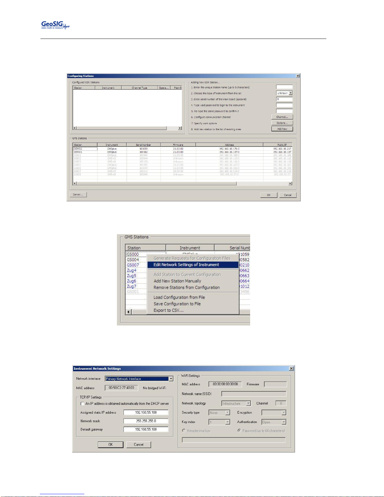
GMSplus User Manual
44 / 124 20.06.2017 / V21
GS_GMSplus_UserManual_V21
8.2. Network Settings through GeoDAS
Under Settings click on Configure Stations…, the following window appears:
Figure 33. Configuring Stations screen
Make a right click on the station name and choose Edit Network Settings of Instrument
Figure 34. Edit Network settings
Adjust all the network parameters in the following screen whereas the Primary Network interface
is the wired Ethernet and Embedded Wi-Fi interface is the wireless network interface.
Figure 35. Configuration of wired Ethernet
Page 45
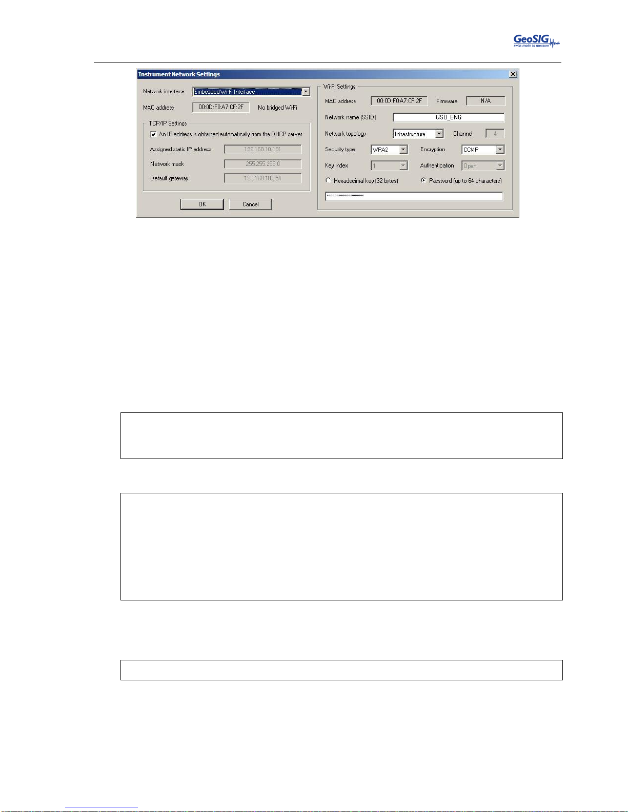
GMSplus User Manual
20.06.2017 / V21 45 / 124
GS_GMSplus_UserManual_V21
Figure 36. Configuration of wireless Ethernet
8.3. Wired Ethernet settings through the local Console
Please see chapter 7.2 for details.
8.4. Wireless Settings through the local Console
Switch on the instrument by pressing and holding the POWER button for 2 seconds.
Press <Ctr> + ‘Z’ as soon the following message appears on the console to enter the test mode.
GMSplus s/n 100582. Firmware in the Linux image: 21.11.00
#################################################
###### Test and Initial Configuration Mode ######
#################################################
Press Ctrl+Z to enter the test mode.....
The following menu will appear (see chapter 12 for details):
Press Ctrl+Z to enter the test mode................
Instrument serial number: 100582
Instrument MAC address: 00:50:C2:77:42:93
-------------------------------------------------------------------------------------------Level Shortcut Password Description
-------------------------------------------------------------------------------------------User Ctrl+U None Basic operations only
Powerful User Ctrl+W None Also hardware options and pre-selected tests
Administrator Ctrl+A None Also manual tests and altering the FLASH memory content
-------------------------------------------------------------------------------------------Your level [U/W/A] or press B to boot now:
By default, no any passwords are set, so press ‘U’ to enter the User Mode, and then ‘N’ to enter the
menu Network settings and proceed till the following menu appears:
---- Wireless network interface ---Static IP address (1=YES, 0=AUTO)?
Select if the instrument should have a static or a dynamic IP by pressing ‘1’ (Static) or ‘0’
(dynamic). In case a dynamic IP is chosen, a DHCP server must be available in the network to
provide the IP settings.
In case a static IP is selected, an additional message will appear asking for the Instrument IP
address, Instrument network mask and Instrument gateway IP. If you don’t know these parameters
please ask your network administrator.
Page 46
GMSplus User Manual
46 / 124 20.06.2017 / V21
GS_GMSplus_UserManual_V21
By pressing ‘E’ the instrument scans the available networks and lists them. Choose the network to
connect by pressing the number next to the network SSID or press ‘C’ to configure the network
settings manually.
Scanning wireless networks.
--------------------------------------------------------------------------- N Network SSID Mode Encryption Channel Level,%
--------------------------------------------------------------------------- 1 GSO_ENG Infrastructure WPA2 1 81
---------------------------------------------------------------------------Enter the number of a network above, <S>can again or <C>onfigure manually:
If the network is encrypted, please enter the network key.
Passphrase (8-63 ASCII) or a 64-character hex key (ad43Fd2d22):
Adjust the other parameters concerning the SSH or recovery server if required.
When the instrument tries to connect to the network, this can take a while. Please be patient till the
following menu appears again:
Bootloader Menu of the GMSplus s/n 100577
Access level: User
--- Flash Images and Boot Options --L - List flash images
Q - Reset instrument configuration to the user default
V - Reset instrument configuration to the factory default
5 - Boot now
X - Reboot the instrument
Y - Power off
--- Hardware Setup and Monitor --N - Network settings
--- Security --O - Set password
-->
Press ‘5’ to continue the boot process of the instrument.
Page 47

GMSplus User Manual
20.06.2017 / V21 47 / 124
GS_GMSplus_UserManual_V21
8.5. Get IP from Instrument
To get the IP from the instrument please press ‘S’ in the main user menu
GMSplus s/n 100582 version 21.11.00
Main menu:
C - Configuration
M - Messages ->
S - Shell command
L - List firmware images
X - Display errors (0) and warnings (0)
W - Clear errors and warnings
F - View/reset RTC trim values
T - File statistics
G - View RTC status
P - View GPS information
H - Set RTC time
U - User request
R - Restart
Q - Quit
Enter the Linux command ifconfig and the following reply will be shown by the instrument
Please see the IPs of the wired Ethernet (eth0) and the wireless Ethernet (wlan0) listed and
marked here in red.
Linux Command: ifconfig
eth0 Link encap:Ethernet HWaddr 00:50:C2:77:42:8E
inet addr:192.168.10.133 Bcast:192.168.10.255 Mask:255.255.255.0
inet6 addr: fe80::250:c2ff:fe77:428e/64 Scope:Link
UP BROADCAST RUNNING MULTICAST MTU:1500 Metric:1
RX packets:71 errors:0 dropped:1 overruns:0 frame:0
TX packets:16 errors:0 dropped:0 overruns:0 carrier:0
collisions:0 txqueuelen:1000
RX bytes:6538 (6.3 KiB) TX bytes:1678 (1.6 KiB)
Interrupt:21 Base address:0x4000
lo Link encap:Local Loopback
inet addr:127.0.0.1 Mask:255.0.0.0
inet6 addr: ::1/128 Scope:Host
UP LOOPBACK RUNNING MTU:16436 Metric:1
RX packets:3 errors:0 dropped:0 overruns:0 frame:0
TX packets:3 errors:0 dropped:0 overruns:0 carrier:0
collisions:0 txqueuelen:0
RX bytes:172 (172.0 B) TX bytes:172 (172.0 B)
wlan0 Link encap:Ethernet HWaddr 00:0D:F0:8E:05:DF
inet addr:192.168.10.94 Bcast:192.168.10.255 Mask:255.255.255.0
inet6 addr: fe80::20d:f0ff:fe8e:5df/64 Scope:Link
UP BROADCAST RUNNING MULTICAST MTU:1500 Metric:1
RX packets:2333 errors:0 dropped:95 overruns:0 frame:0
TX packets:636 errors:0 dropped:0 overruns:0 carrier:0
collisions:0 txqueuelen:1000
RX bytes:271699 (265.3 KiB) TX bytes:737148 (719.8 KiB)
Page 48
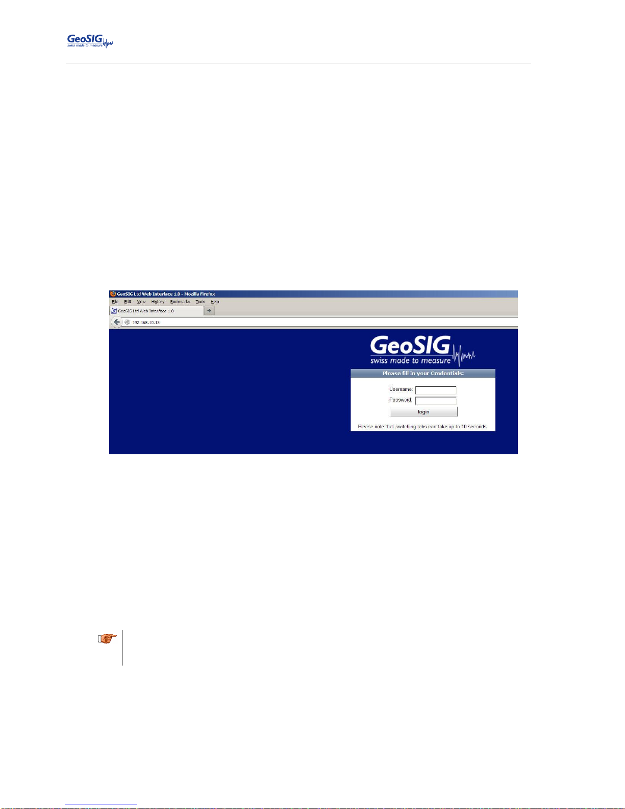
GMSplus User Manual
48 / 124 20.06.2017 / V21
GS_GMSplus_UserManual_V21
9. The Web Interface
The instrument can be configured over a Web Interface. To be able to use the Web Interface, it is necessary
that the following criteria are fulfilled:
The IP Address of the device has to be known or the flag Keep connection to the server is enabled
under Server Parameters (see chapter 10.8 for details) must be enabled (Yes)
In case the flag Keep connection to the server is disabled, the port 80 of the device has to be
accessible, from the accessing computer. This usually means that the instrument is in the same
network as the accessing computer and no firewall mechanism separates the two.
A current browser version has to be available on the accessing computer.
9.1. Accessing the Web Interface
To access the instrument please follow one of the following two steps.
▪ In the window Stations: General Information of GeoDAS make a right click on the station name
and click on Instrument Setup …, or
▪ Open your browser and enter the IP-Address (e.g. 192.168.10.13) of the device in the address
bar of your browser, as can be seen previously in Figure 35.
Figure 37. The login screen of the instrument at 192.168.10.13
To be able to adjust the configuration of the instrument or access its data, it is required to authenticate
oneself to the device. This can be done by entering a valid username and corresponding password in the
fields of the same name and pressing the “login” button.
The default login credentials are:
Username: admin
Password: 123456
The default password can be changed as described in the chapter 9.3.4 of this manual. If the admin
password is forgotten, please delete the webuser.txt file on the SD/CF card of the instrument to restore the
default password.
a
The Web Interface can be disabled under Network settings in the Administrator mode of the
test and configuration menu. See chapter 11 for details.
Page 49
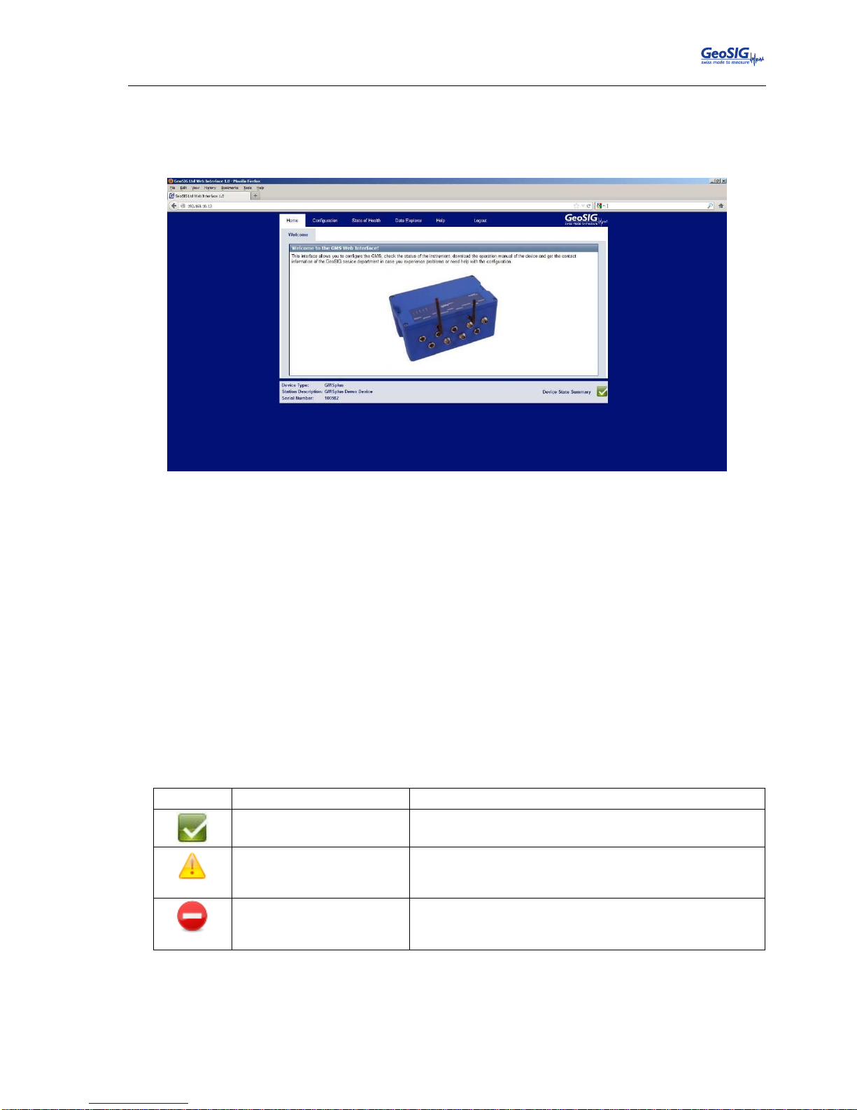
GMSplus User Manual
20.06.2017 / V21 49 / 124
GS_GMSplus_UserManual_V21
9.2. The Home Panel and the General Navigation
After the login process has ended, the screen shown in Figure 388 becomes visible. The width of the Web
Interface is optimised for a screen width of 1024 pixels. If the width of the browser window is smaller than
that, it might be necessary to scroll horizontally.
Figure 38. The home panel of the web interface
As can be seen in Figure 39, each screen in the web interface is separated into three sections:
1. The Navigation Bar: The navigation bar allows accessing all screens within the web interface. The
navigation bar is further separated into two parts. The top bar is the primary navigation panel which
is visible from all screens. The currently active tab is marked white, while all other -- inactive -- tabs
are blue. By changing from one tab to another, the secondary navigation panel becomes active. This
secondary navigation tab allows to switch between the actual screens within a primary navigation
bar.
2. The Content Section: This section will contain all information and configuration options. Most
interaction will take place in this part.
3. The Device State Summary: On the left side the Station Description and Serial Number is displayed
to identify the current instrument you are working on. On the right side the device state summary
describes the overall status of the instrument. The states that are possible are listed in Table 7. By
clicking on the overall state, information on the actual problems will be displayed. More detailed
information on the error states are provided in the menu item “State of Health” as described in
chapter 9.4.
Symbol
Meaning
Description
No errors or warnings
reported from the device.
As there seem to be no issues, no action is required.
A warning is reported from
the device
There seems to be an issue in this module. Although it
seems not to be critical, it is recommended to check why
this warning is displayed and take actions to resolve it.
A warning is reported from
the device
An error has occurred and it is required to check for the
cause of the problem and resolve it in order to avoid
limited functionality.
Table 7. The overall error states shown in the Web Interface
Page 50
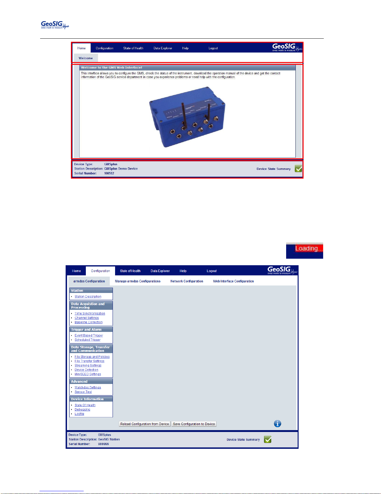
GMSplus User Manual
50 / 124 20.06.2017 / V21
GS_GMSplus_UserManual_V21
Figure 39. Division of the screen in the web interface
9.3. Device Configuration
The configuration screen of the Web Interface gives access to all configuration options, the configuration
management of the Data Acquisition Software as well as the Network Configuration and the Web Interface
itself.
Loading the configuration can take several seconds. During this time at the right corner of
the browser Loading… is displayed. Please be patient till the screen shown in Figure 4040
appears.
Figure 40. Configuration main menu
2 1 3
Page 51
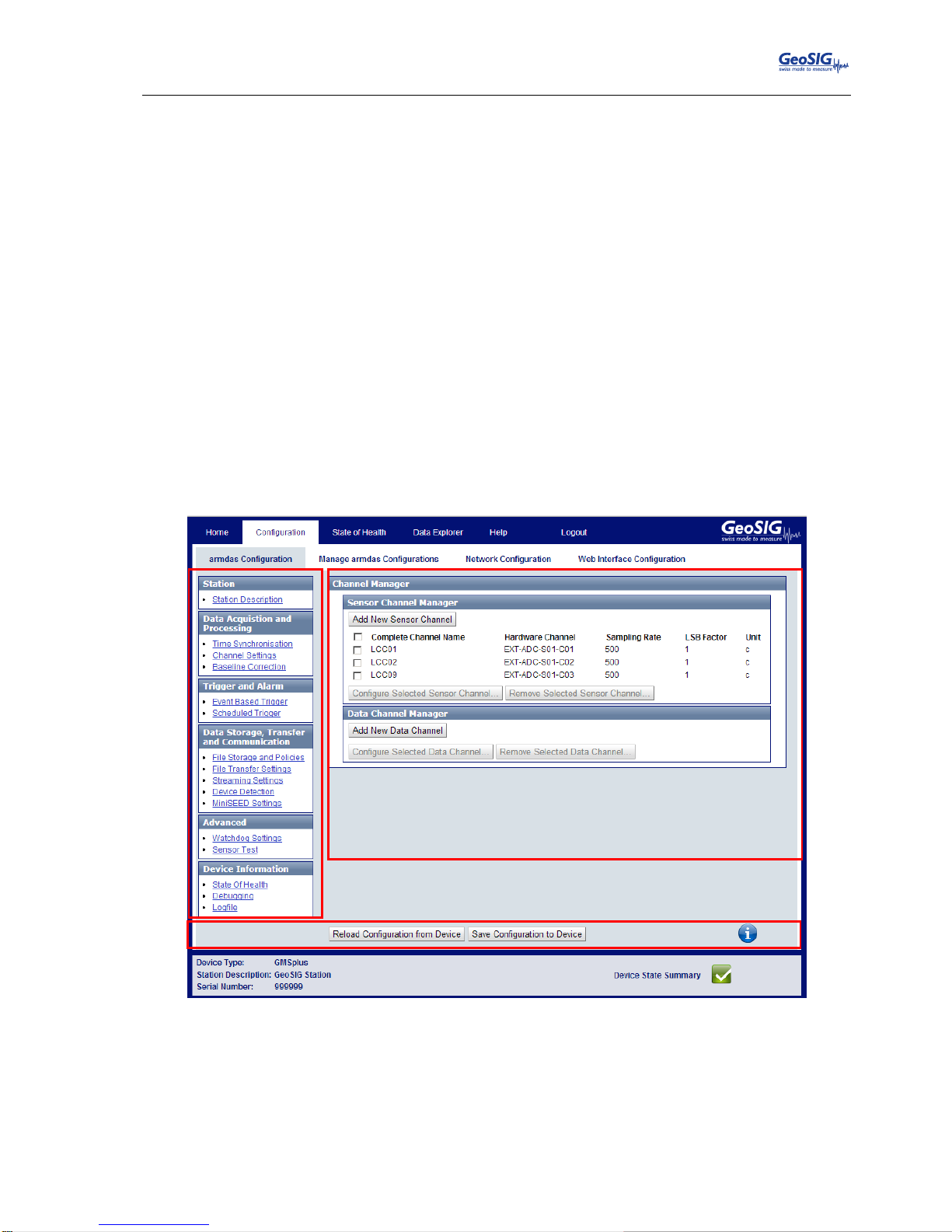
GMSplus User Manual
20.06.2017 / V21 51 / 124
GS_GMSplus_UserManual_V21
9.3.1. armdas Configuration
The armdas Configuration sub menu provides access to the current armdas configuration options. Armdas
is the data acquisition program running on the instrument. As depicted in Figure 41, the content of this tab is
divided into three sections:
1. The Configuration Menu: The Configuration Menu is the additional navigation menu through the
currently active configuration in this particular screen. By switching between the listed items in this
menu, the Configuration Value Panel can be changed.
2. The Configuration Value Panel: This is main part of the armdas Configuration screen. Within this
part of the screen all the values of the configuration of the selected Configuration Menu Item can be
adjusted. Most options will provide a help button in the form of white question mark on blue ground
on the right part of this section. By clicking on it information will be displayed over the option.
Please note that the only way to restore the original values of the fields after making changes to
them is by using the “Reload Configuration from Device” Button in the Action Panel.
3. The Action Panel: This panel is providing the option to either reload the current configuration from
the device (to discard changes or load changes done by another user) or to save the edited
configuration to the device. By saving the changes to the device, the data acquisition software
armdas will be restarted to load the new configuration. This will interrupt the current recording for
about 20 seconds. During this time triggers will not be executed either. Please note that if the device
is configured to use a DHCP server, the address might change during the saving of the configuration
which will make the web interface inaccessible under the old address.
Figure 41. The armdas Configuration screen
2
3
Page 52
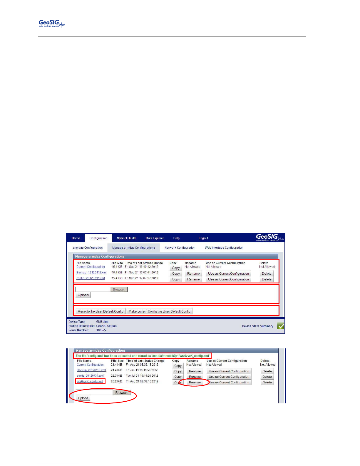
GMSplus User Manual
52 / 124 20.06.2017 / V21
GS_GMSplus_UserManual_V21
9.3.2. Manage armdas Configurations
As described in the previous chapter, the armdas Configuration screen only allows configuring the currently
used configuration. The Manage armdas Configurations screen described in this chapter allows managing
several configurations, changing the current configuration, uploading a new configuration and so on. As
depicted in Figure 42, the screen is divided into three sections:
1. The Configuration List: This list contains all configurations currently available on the SD or CF
card. The Current Configuration should always be listed in this list. This configuration can be copied
and downloaded but not renamed, removed or made the current configuration (as it is already the
current). As depicted in Figure 43, these options become available to other configurations stored on
the SD or CF card (in this example after uploading a file to the device). When pressing Use as
Current Configuration it will store this configuration as the Current Configuration. The existing
configuration will be overwritten and the instrument restarted. Note that only the Current
Configuration can be edited in the armdas Configuration screen. The other configuration files will
remain untouched. The Current Configuration can be saved in a file by pressing Copy.
2. The Upload Panel: While the Configuration List allows downloading configurations from the device
by clicking on the name, this part of the screen provides the possibility to upload a configuration to
the web interface by selecting a configuration on the PC and using the Upload Button. As can be
seen in Figure 433, after a successful upload a new file is shown in the Configuration List and the
name of the newly available configuration is written at the top of the list. (The name of new
configuration will be created from a random string followed by “_config.xml”). The configuration can
then be changed by clicking on Rename. Note that the upload panel might look different depending
on the browser in use.
3. User Default Panel: With the Reset To Default Config, the Current Configuration will be
overwritten by the user default (see command SETDEFCFG in the chapter 10.11.1) and the
instrument will be restarted. The Current Configuration can be saved as the user default by pressing
the button Make current Config the User Default Config
Figure 42. The Manage armdas Configurations screen
Figure 43. New file upload
1 23
Page 53
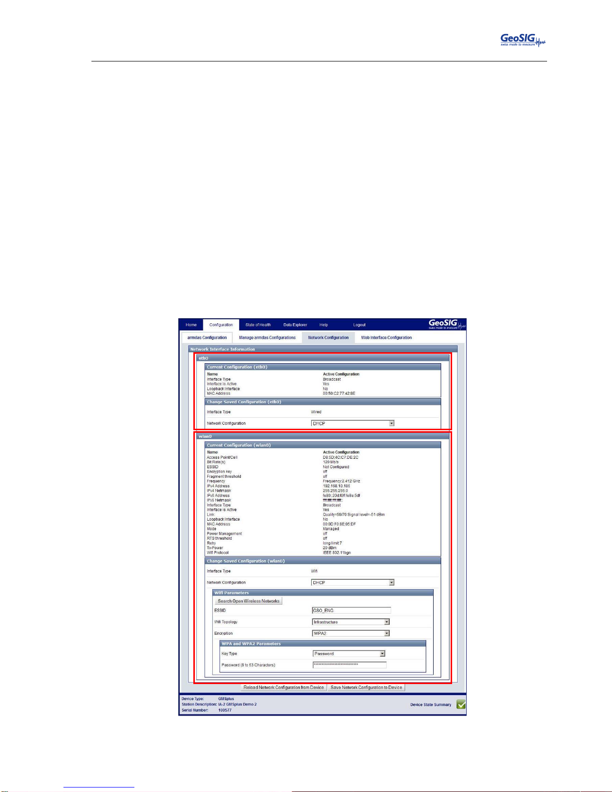
GMSplus User Manual
20.06.2017 / V21 53 / 124
GS_GMSplus_UserManual_V21
9.3.3. Network Configuration
9.3.3.1. Wired Ethernet
The Network Configuration screen provides the possibility to change the network configuration of all network
interfaces of the instrument. For the standard instrument only one network interface is available: the Ethernet
interface, which is present in all devices. (This interface is marked as “LAN” in Figure 55). This interface can
be configured in the section of the screen that is marked with the red number “1” in Figure 444. The top part
of that framed, red section describes the current configuration of the interface. The part below allows
changing this configuration. The name of this network interface is traditionally eth0.
9.3.3.2. Wi-Fi Wireless Ethernet
Some devices contain an additional wireless interface (marked as “Wi-Fi” in Figure 55). If this is the case, a
second configuration panel is shown in the Network Configuration screen as can be seen Figure 444
(marked with the red number “2”). As with the default Ethernet interface the section surrounded by the red
frame is split in two parts, where the top part defines the current settings and the bottom part provides the
possibility to change the configuration. Additionally to the standard network settings like IP Address,
Netmask, Gateway and so on, the actual wireless settings can be adjusted and open wireless networks
scanned. The name of this network interface is traditionally wlan0.
Figure 44. Network Configuration Screen
1
2
Page 54
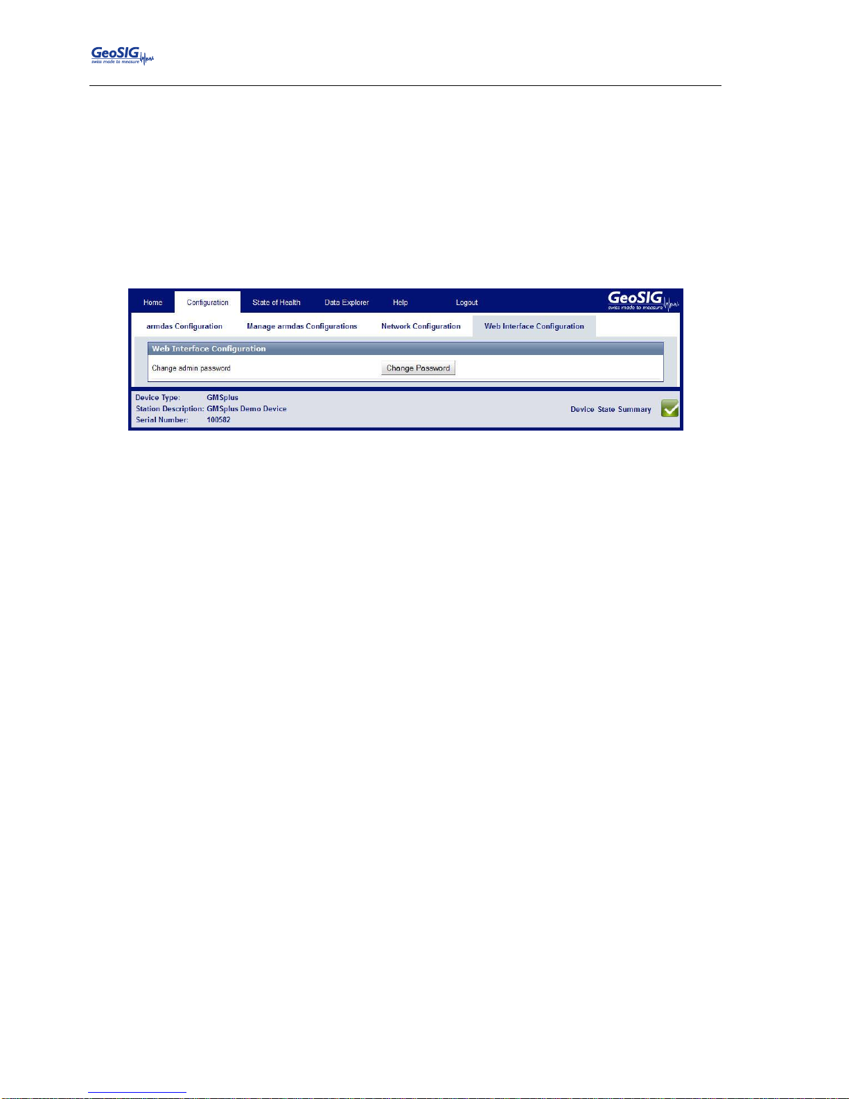
GMSplus User Manual
54 / 124 20.06.2017 / V21
GS_GMSplus_UserManual_V21
9.3.4. Web Interface Configuration
The Web Interface Configuration screen allows configuring all settings related to the Web Interface. At the
moment, this solely consists of the possibility of changing the password for the login. To change the
password press Change Password. The current password has to be known.
The default login credentials are:
Username: admin
Password: 123456
If the admin password is forgotten, please delete the webuser.txt file on the SD or CF card and restart the
instrument to restore the default password.
Figure 45. Web Interface Configuration Screen
9.4. State of Health
The State of Health (SOH) menu item provides all information related to the error status of the device as well
as the status of the available hardware and software versions.
9.4.1. Error Status
As depicted in Figure 466, this screen provides basic information on the device at hand (area 2) as well as
the error status for each module (area 3). The summary of this SOH information is visible at the bottom of
each page as the Device State Summary, described in chapter 9.2. Additionally it is possible to download the
State of Health information as a file in XML format -- this is possible in all sub-menu items of the State of
Health menu -- and clear the errors (area 1).
Page 55
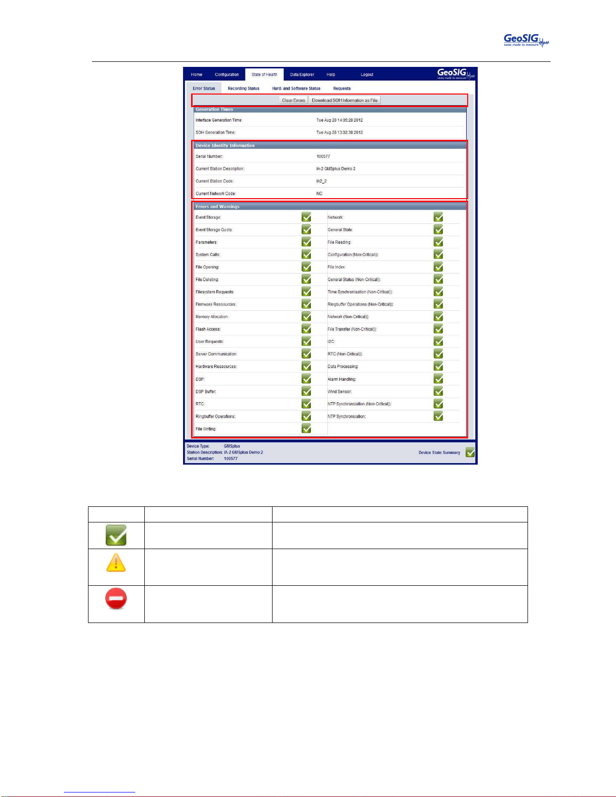
GMSplus User Manual
20.06.2017 / V21 55 / 124
GS_GMSplus_UserManual_V21
Figure 46. Error Status Screen
The modules in area 3 can have one of the states defined in Table 8.
Symbol
Meaning
Description
No errors or warnings
reported from the device.
As there seem to be no issues, no action is required.
A warning is reported from
the device
There seems to be an issue in this module. Although it
seems not to be critical, it is recommended to check why
this warning is displayed and take actions to resolve it.
A warning is reported from
the device
An error has occurred and it is required to check for the
cause of the problem and resolve it, in order to avoid
limited functionality.
Table 8. The overall error states shown in the Web Interface
1 23
Page 56
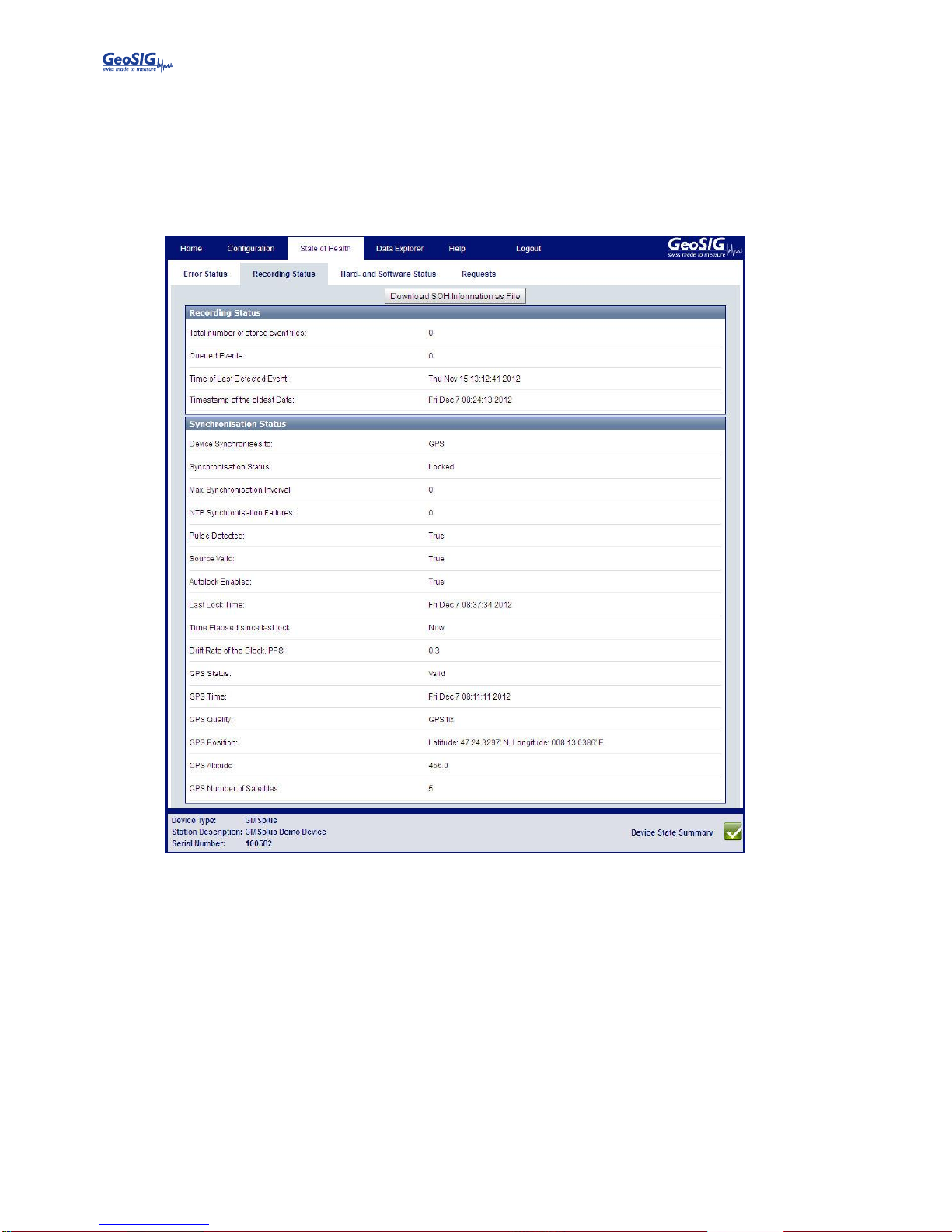
GMSplus User Manual
56 / 124 20.06.2017 / V21
GS_GMSplus_UserManual_V21
9.4.2. Recording Status
This screen provides all information on the recording and time synchronisation status of the device. As
depicted in Figure 477, this screen contains information on the number of events, the timing and
synchronisation status of the device, as well as information about the GPS quality and the GPS position of
the instrument.
Figure 47. Recording Status Screen
Page 57
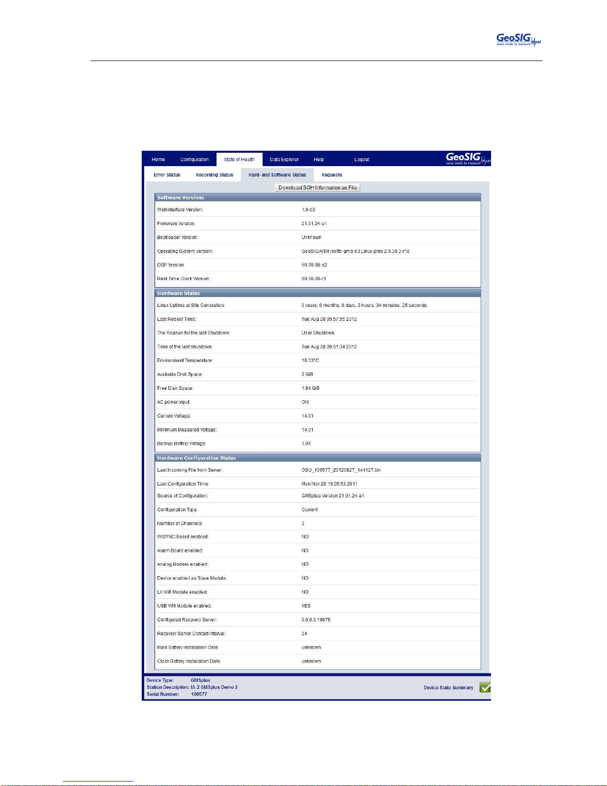
GMSplus User Manual
20.06.2017 / V21 57 / 124
GS_GMSplus_UserManual_V21
9.4.3. Hard- and Software Status
The Hard- and Software Status screen contains information on the Software Versions. The Hardware
Status provides such information as uptime, available disk space, the device temperature and so on.
Information about the available hardware options in the instrument, such as Alarm Boards, Wi-Fi Modules
and Modems can be found in the section Hardware Configuration Status.
Figure 48. Recording Status Screen
Page 58
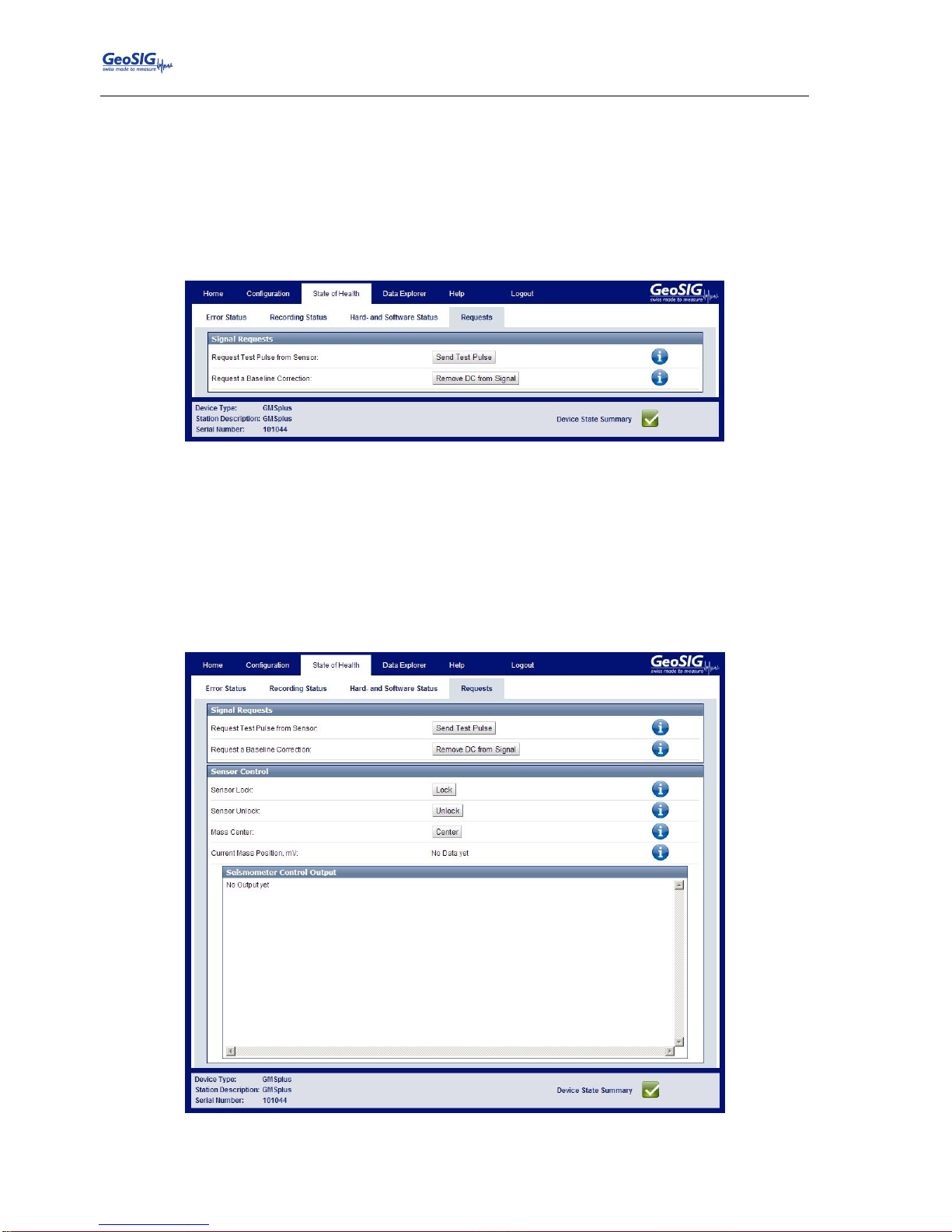
GMSplus User Manual
58 / 124 20.06.2017 / V21
GS_GMSplus_UserManual_V21
9.4.4. Requests
As shown in Figure 499, the Requests screen enables sending signal-related requests to the data acquisition
software. Currently two such signal requests are supported:
Send a Test Pulse: By sending this request, a test pulse will be executed. The sensor should then
respond accordingly and thus provide information about its status.
Remove DC from Signal: By sending this request, a baseline correction will be applied to the
signal and therefore remove the DC from the value, caused by e.g. a slight misalignment of the
sensor.
Figure 49. The Requests Screen
If the Seismometer Control option is available, it is possible to control the mass from this window as well as
can be seen in Figure 5050. The following commands are supported:
Lock: Locks the seismometer.
Unlock: Unlocks the seismometer. After unlocking, the sensor automatically centres its mass.
Center: Centring of the mass
During all controls, the field Current Mass Position shows current pass positions of the channels E/W, N/S
and V in mV. Feedback about the progress and status information can be found under Seismometer Control
Output.
Figure 50. Seismometer Control
Page 59
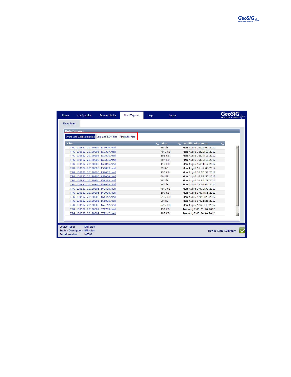
GMSplus User Manual
20.06.2017 / V21 59 / 124
GS_GMSplus_UserManual_V21
9.5. Data Explorer
The Data Explorer provides the possibility to gather information on the files stored on the SD or CF card. The
file types are separated into three different file types:
Event- and Calibration files
Log- and SOH-files
Ringbuffer files
With the menu at the top of the Data Explorer it is possible it is possible to switch between the file types
listed above. For each listed file, the information on its file size and the last modification time are displayed.
The files can be sorted according to the file name, size or modification date. By clicking on the file name, the
file can be downloaded.
Figure 51. The Data Explorer Screen
Page 60
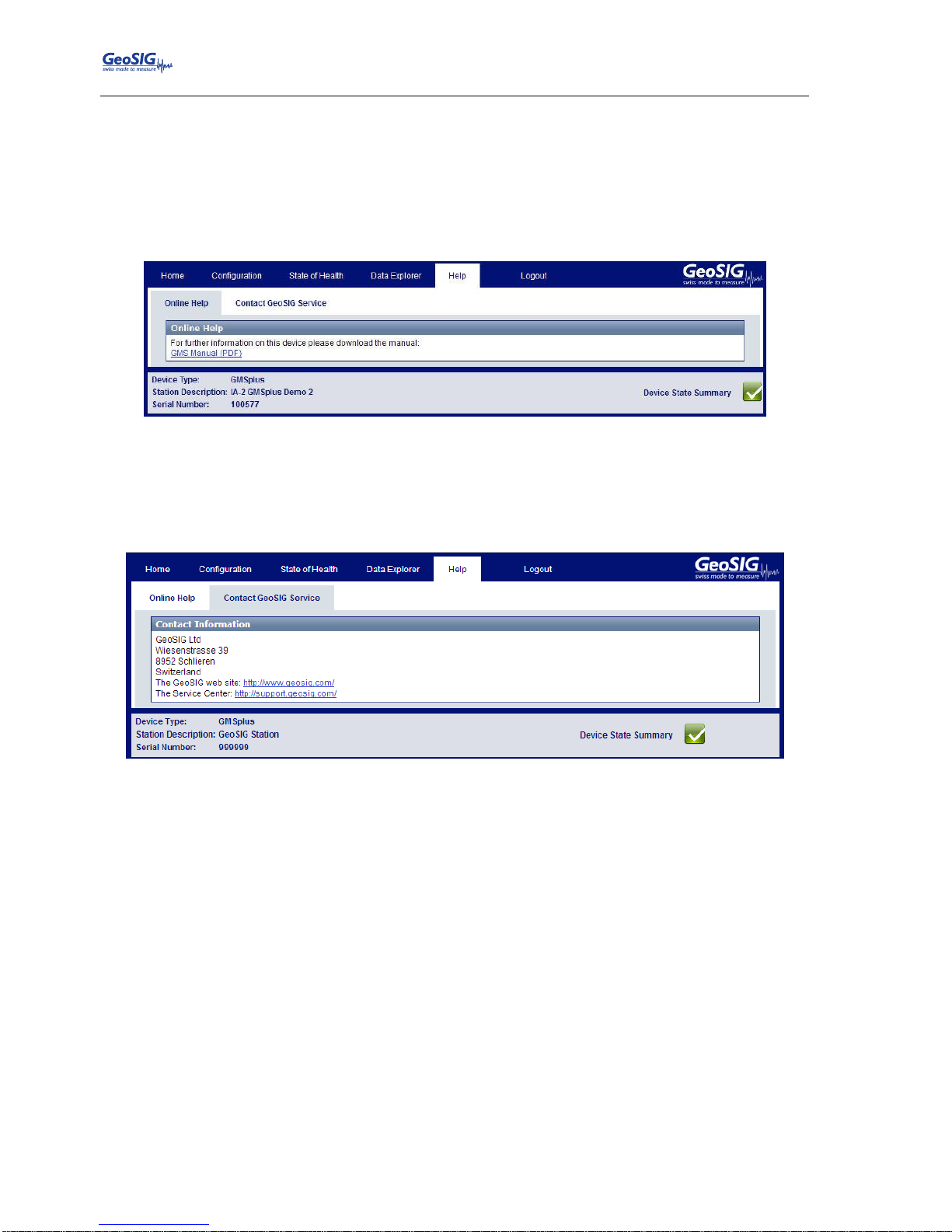
GMSplus User Manual
60 / 124 20.06.2017 / V21
GS_GMSplus_UserManual_V21
9.6. Help
The Help Menu provides help if there are any problems with the device or the web interface.
9.6.1. Online Help
On this screen, the current version of the GMS
plus
User Manual can be downloaded from the device. This
manual contains additional information on the instrument, which is not provided in the interface itself.
Figure 52. Download the GMS
plus
Manual
9.6.2. Contact GeoSIG Service
This screen provides information on how to contact GeoSIG service in the case of problems. The links
provided on this screen will only work if access to the Internet is available.
Figure 53. Contact information
Page 61
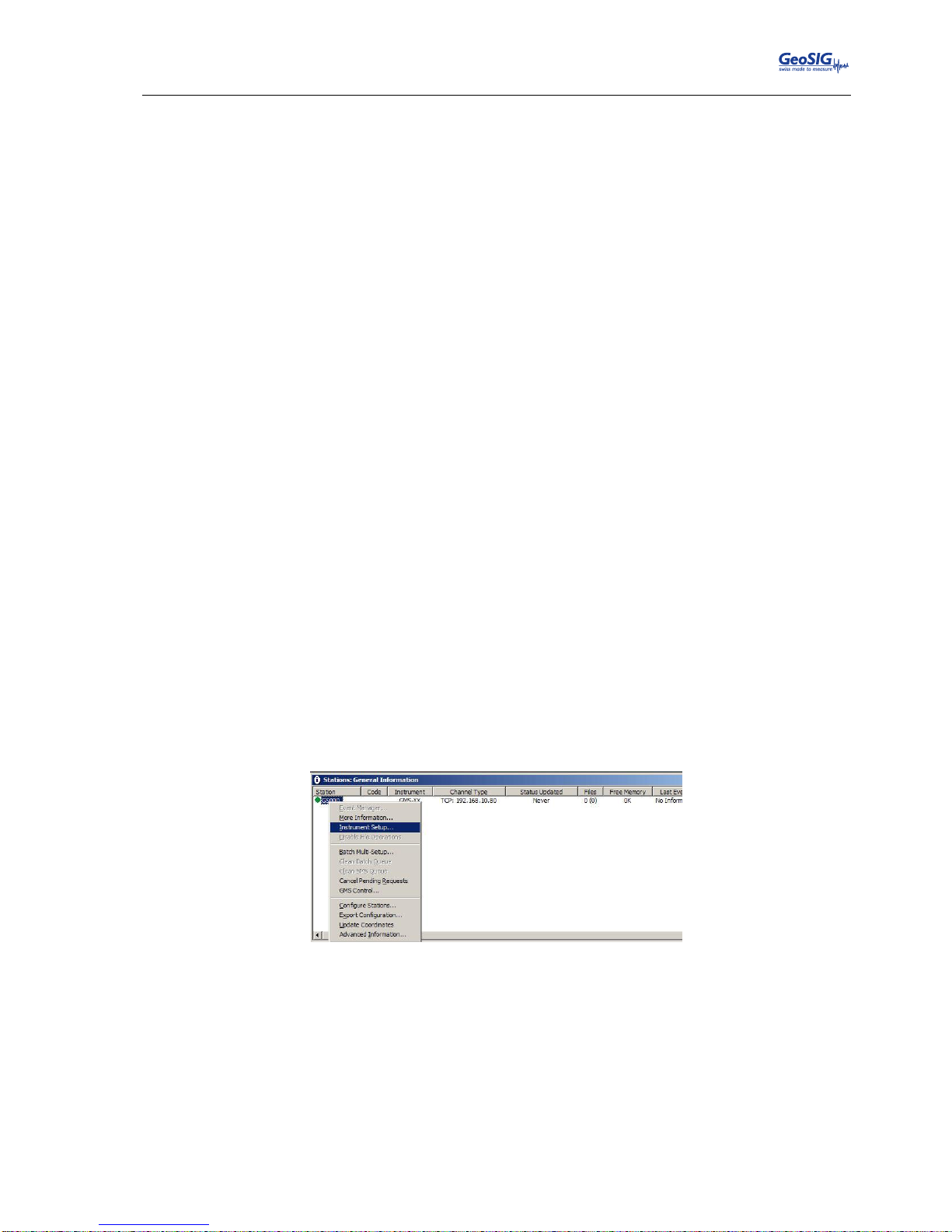
GMSplus User Manual
20.06.2017 / V21 61 / 124
GS_GMSplus_UserManual_V21
10. Detailed Configuration of the Instrument
10.1. Switch ON and OFF the instrument
The main power switch operates as follows:
Open the cover of the instrument by removing the four screws in the corners.
Press the POWER button for 2 seconds to switch the instrument ON.
The green RUN indicator blinks for 0.4 seconds every 2 seconds during the start-up procedure until
it is ready to operate (see Figure 9 and Table 2 for details).
The RUN indicator is blinking one time a second (20% ON) to show normal operation (see Figure 9
and Table 2 for details).
To turn the instrument OFF, press the power button for a minimum of 2 seconds. The RUN
indicator blinks approximately 16 seconds every 2 seconds during shutdown process and then
turns OFF when power is really off. (See Figure 9 and Table 2 for details).
10.2. General Comments to the Configuration
All the configuration changes can be done either over the network by the Web Interface and GeoDAS or on
the instrument itself using a RS-232 cable on the serial connector and a terminal program.
10.2.1. Change Configuration by the Web Interface
Open an Internet browser and enter the IP address of the device in the address bar of your
browser.
Login with the username: admin and the password: 123456
See chapter 9 for the full explanation of the Web Interface.
10.2.2. Change Configuration by GeoDAS
In the window Stations: General Information make a right click on the station name.
Figure 54. Instrument setup
GeoDAS is opening the default Internet browser; the Web Interface of the instrument will appear.
See chapter 9 for the full explanation of the Web Interface.
Page 62
GMSplus User Manual
62 / 124 20.06.2017 / V21
GS_GMSplus_UserManual_V21
10.2.3. Changing Configuration by the Console
Connect the GMS-xx to a serial port of your computer and switch on the GMS-xx if not already
done.
In GeoDAS go to Tools Terminal… and choose your COM Port. As Baud rate select 115200.
Then Press Connect.
Press <Enter>; the following menu appears:
GMSplus s/n 100582 version 21.11.00
Main menu:
C - Configuration
M - Messages ->
S - Shell command
L - List firmware images
X - Display errors (0) and warnings (0)
W - Clear errors and warnings
F - View/reset RTC trim values
T - File statistics
G - View RTC status
P - View GPS information
H - Set RTC time
U - User request
R - Restart
Q - Quit
To configure armdas, from GMS
plus
console, press 'C' and <Enter>. If you are asked, select Edit
current configuration, by pressing ‘C' again.
Change the configuration as described in the following chapters
Press <Esc> to leave the configuration menu. If asked, select save as current configuration, by
pressing ‘C’
Page 63
GMSplus User Manual
20.06.2017 / V21 63 / 124
GS_GMSplus_UserManual_V21
10.2.4. Explanation of the Structure in the Manual
As the parameters in the configuration sometimes depend on each other, not all parameters are shown all
the time. The configuration is also sorted in several sub-menus. Therefore the menu is explained as
following:
Parameter in the menu
Possible selections
or ‘User selectable’
Explanation
Switch-Parameter
Possible selections
or ‘User selectable’
Explanation: The following three lines depend
on the selection and are only visible if not set to
‘No’
This Parameter is only
visible if Switch-Parameter
has been set to Yes
Possible selections
or User selectable
Explanation
This Parameter is only
visible if Switch-Parameter
has been set to Yes
Possible selections
or User selectable
Explanation
Submenu, only visible if Switch-Parameter has been set to Yes
Parameter in the
Submenu
Possible selections
or ‘User selectable’
Explanation
Parameter in the
Submenu
Possible selections
or ‘User selectable’
Explanation
Parameter in the
Submenu
Possible selections
or ‘User selectable’
Explanation
Parameter in the
Submenu
Possible selections
or ‘User selectable’
Explanation
Switch-Parameter in the
Submenu
Possible selections
or ‘User selectable’
Explanation
This Parameter is only
visible if SwitchParameter has been
set to Yes
Possible selections
or ‘User selectable’
Explanation
Table 9. Explanation table structure
Page 64
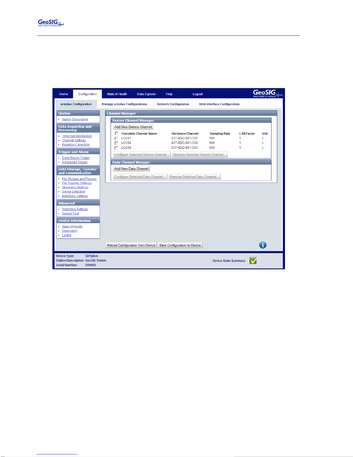
GMSplus User Manual
64 / 124 20.06.2017 / V21
GS_GMSplus_UserManual_V21
10.3. Configuration of the Channels
10.3.1. In the Web Interface or by GeoDAS
Go to Configuration armdas Configuration Channel Settings
Figure 55. Channel Settings
Add new sensor or virtual channels by the buttons Add New Sensor Channel or Add New Data
Channel. Channels can be removed again by Remove.
To edit a channel press the button Edit and adjust the parameters in the pop-up window. See
Table 10 for additional information.
Page 65
GMSplus User Manual
20.06.2017 / V21 65 / 124
GS_GMSplus_UserManual_V21
10.3.2. Via Local Serial Console
Press ‘E’ to select the number of channels. By default three channels are configured as most
sensors have three channels normally.
Main Menu
A) Station description ............. Demo GMSplus
B) Station code .................... DEMO
C) Location description ............ Switzerland
D) Seismic network code ............ CH
E) Number of Channels .............. 3
F) Number of Output Streams ........ 1
G) Number of Trigger Sets .......... 1
H) Number of Preset Triggers ...... 0
I) Channel Parameters .............. ->
J) Stream Parameters ............... ->
K) Trigger Parameters .............. ->
M) File Storage and Policy ......... ->
N) Communication Parameters ........ ->
O) Miscellaneous Parameters ........ ->
Press ‘I’ to get to the Channel Parameters menu to adjust the settings of the channels. The
following menu appears:
Main Menu | Channel 1 of 3
A) Data source ..................... INT-ADC-S01-C01
E) Channel name .................... C01
F) Location code ................... CH
G) Data unit ....................... g
H) LSB factor ...................... 3.97364e-007
I) Sampling rate, sps .............. 200 (0xC8)
K) Negative axis ................... No
L) Offset compensation ............. No
N) Maintain the ringbuffer ......... Yes
R) Decimation and peaks ............ None
Each channel can be adjusted according to your wishes. To change the channels press ‘+’ or ‘-‘.
The following parameters can be adjusted:
Page 66
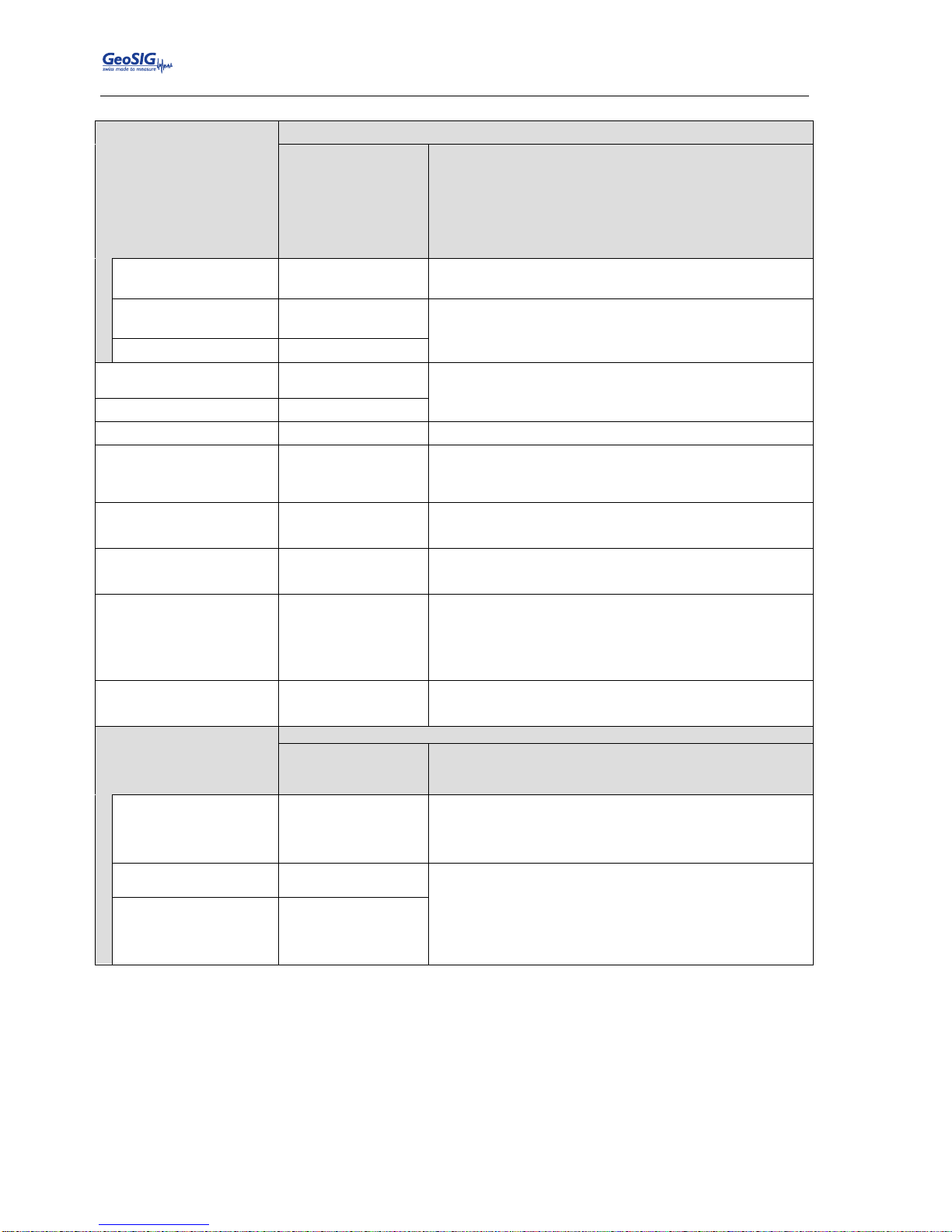
GMSplus User Manual
66 / 124 20.06.2017 / V21
GS_GMSplus_UserManual_V21
Data source
The source of the channel can be defined
INT-ADC-Sxx-Cxx
EXT-ADC-Sxx-Cxx
DATACHAN
DATAVSUM
DATAVSU3
See chapter 10.3.4
Virtual channels
Vector sum of two channels
Vector sum of three channels
Source channel
name
User selectable
The source of the virtual channel can be any other
channel
Second source
channel
User selectable
In case of the vector sum a second or third source has to
be selected
Third source channel
User selectable
Channel name
User selectable
The channel name in the record is a combination of the
location code and channel name
Location code
User selectable
Data unit
User selectable
Data unit of the selected channel
LSB factor
User selectable
LSB factor, depending on the connected sensor. See
chapter 10.3.3 for details and Table 11 for the specific
values of the sensors.
Sampling rate
50, 100, 200, 250,
500, 1000
*
Sampling rate of the selected channel
* 1000 SPS only valid with 3 channels or less.
Negative axis
Yes
No
Inversion of the axis is enabled
Inversion of the axis is disabled
Offset compensation
Yes
No
Compensation is enabled
Compensation is disabled
Detail behavior of the offset compensation can be
configured as described in chapter 10.9.2
Maintain Ringbuffer
Continuously Record Data
Yes
No
Permanent recording is enabled
Permanent recording is disabled
Decimation and peaks
Online Decimation
The data can be decimated, or just peaks can be stored
Decimation
Peak Values
Average Values
Additional down sampling of the data
Peak values of the data within a certain interval
Average values of the data within a certain interval
Decimation factor
User selectable
The signal will be decimated by the selected factor. E.g.
if the sample rate is 50 and the decimation factor 10,
then the output sample rate is 5 SPS. Be aware that no
anti-aliasing filtering is done prior to decimation!
Interval of averaging,
sec
User selectable
The Peak or Average values of the signal within the time
defined in the Interval of averaging will be written into the
ringbuffer with the specified Output sampling interval in
[seconds].
Interval of averaging should be equal or higher than the
Output sampling interval.
Output sampling
interval
User selectable
Table 10. Channel configuration menu structure
Page 67
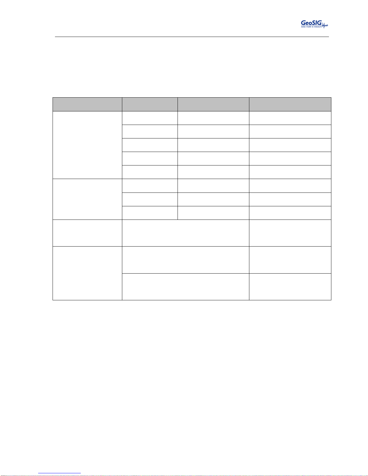
GMSplus User Manual
20.06.2017 / V21 67 / 124
GS_GMSplus_UserManual_V21
10.3.3. Calculation of the LSB factor
In the Web Interface, the conversion from LSB to Full Scale and backwards is done automatically. In case
the instrument is configured over GeoDAS or the console, the LSB value must be entered.
10.3.3.1. Overview
The LSB’s of all GeoSIG sensors can be found in the following table
Sensor type
Full Scale
Output Voltage Range
LSB
AC-xx
0.5 g
+/- 10 V
0.662’274e-7 g/count
1 g
+/- 10 V
1.324’548e-7 g/count
2 g
+/- 10 V
2.649’095e-7 g/count
3 g
+/- 10 V
3.973’643e-7 g/count
4 g
+/- 10 V
5.298’191e-7 g/count
VE-13
VE-23
1 mm/s
+/- 10 V
1.324’548e-7 mm/s/count
10 mm/s
+/- 10 V
1.324’548e-6 mm/s/count
100 mm/s
+/- 10 V
1.324’548e-5 mm/s/count
VE-33
Sensitivity: 27.3 V/m/s (27.3 Vs/m)
4.851’822e-8 m/s/count
4.851’822e-5 mm/s/count
VE-53
Sensitivity: 1000 V/m/s (2x 500 V/m/s)
1.324’548e-9 m/s/count
1.324’548e-6 mm/s/count
Sensitivity: 200 V/m/s (2x 100 V/m/s)
6.622’738e-9 m/s/count
6.622’738e-6 mm/s/count
Table 11. LSB of all GeoSIG sensors
If you have a different kind of sensor, the LSB can be calculated according to the following chapters.
Page 68
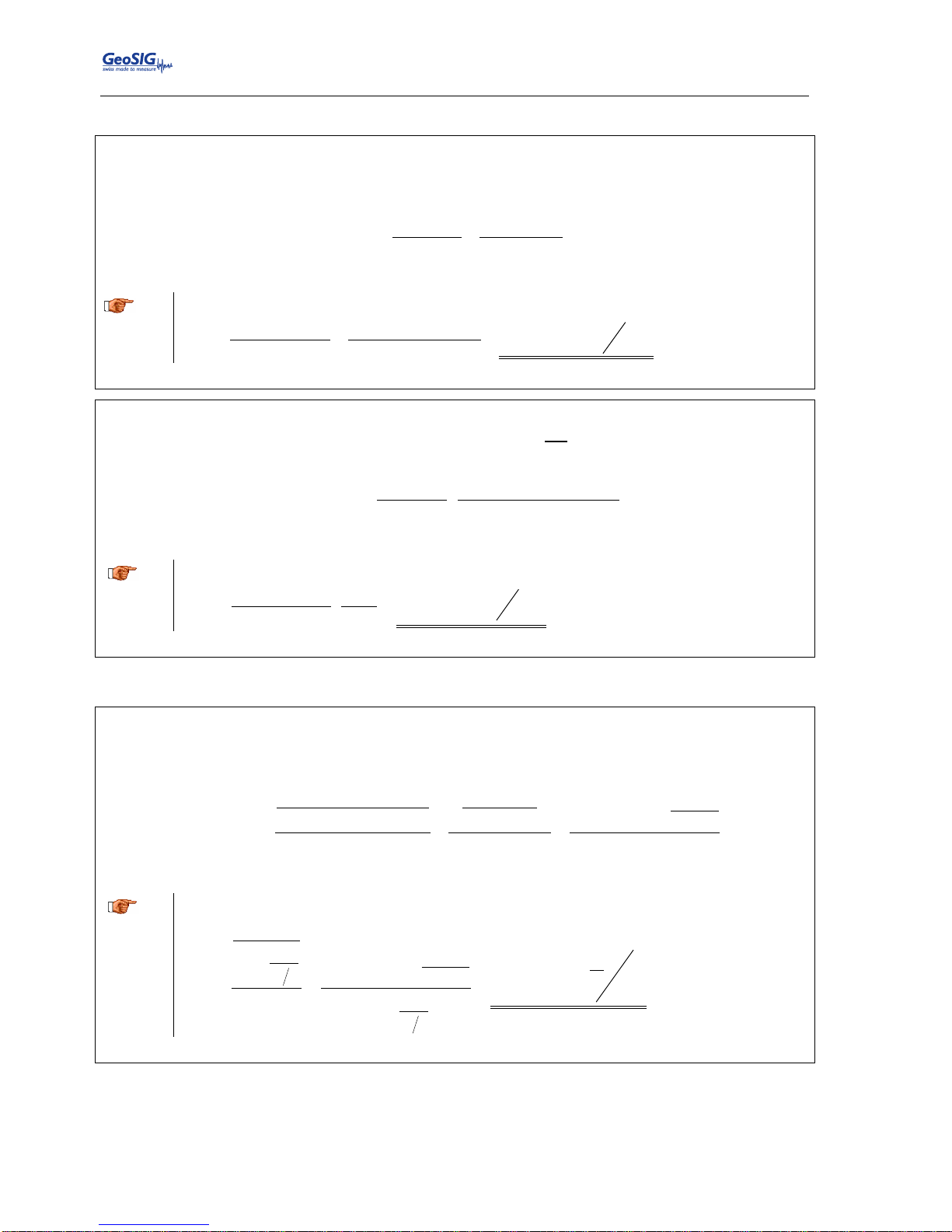
GMSplus User Manual
68 / 124 20.06.2017 / V21
GS_GMSplus_UserManual_V21
10.3.3.2. Calculate LSB from Sensors with given Full Scale
Output Voltage of the sensor and input range of the recorder is +/- 10 V (GeoSIG Standard)
LSB
=
FullScale
0.9×2
23
=
FullScale
7'549'747.2
A
Example, 3 g sensor
LSB
=
3g
0.9×223counts
=
3g
7'549'747.2 counts
=3.973643e-7
g
count
Output Voltage of the sensor and input range of the recorder is not +/- 10 V
LSB
)(
)(Re
29.0
23
VScaleSensorFull
VScalecorderFullFullScale
a
Example, 3 g sensor with +/- 2.5 V connected to a recorder with +/- 10 V input range
LSB
count
e
V
V
counts
g
g
6589457.1
5.2
10
29.0
3
23
10.3.3.3. Calculate LSB from Sensors with given Sensitivity
Input range of the recorder is +/- 10 V (GeoSIG Standard)
LSB
ySensitivit
counts
V
e
counts
ySensitivit
V
counts
ySensitivit
VllScalerecorderFu
6324547.1
29.0
10
29.0
2323
a
Example, 1000 V/m/s sensor
LSB
count
s
m
e
sm
V
counts
V
e
sm
V
V
9324547.1
1000
6324547.1
29.0
1000
10
23
Page 69
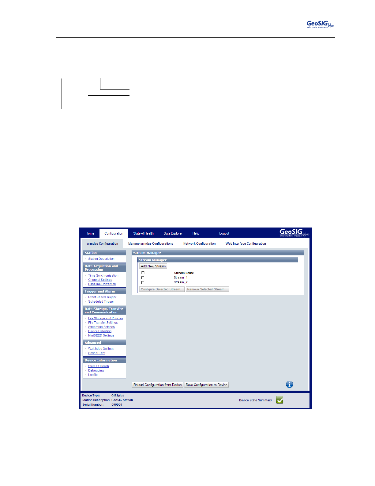
GMSplus User Manual
20.06.2017 / V21 69 / 124
GS_GMSplus_UserManual_V21
10.3.4. Channel Naming
The naming of the channels is organised as following: all internal sensors start with INT-ADC, all external
sensors with EXT-ADC.
xxx-ADC-Sxx-Cxx
Channel
C01 … C03
Sensor
3ch: S01
6ch: S01, S02
Sensor number
Source
INT
EXT
Internal Sensor
External Sensor
For example if there are two external sensors connected, the following channels are available:
EXT-ADC-S01-C01
EXT-ADC-S01-C02
EXT-ADC-S01-C03
EXT-ADC-S02-C01
EXT-ADC-S02-C02
EXT-ADC-S02-C03
10.4. Configuration of Data Streams
10.4.1. In the Web Interface or by GeoDAS
Go to Configuration armdas Configuration Streaming Settings
Figure 56. Streaming Settings
Add new data stream channels by the button Add New Stream. Streaming channels can be
removed again by Remove.
To edit a streaming channel press the button Edit and adjust the parameters in the pop-up window.
See Table 12 for additional information.
Page 70
GMSplus User Manual
70 / 124 20.06.2017 / V21
GS_GMSplus_UserManual_V21
10.4.2. Via Local Serial Console
Press ‘F’ to select the Number of Output Streams. One output stream can have several channels.
Main Menu
A) Station description ............. Demo GMSplus
B) Station code .................... DEMO
C) Location description ............ Switzerland
D) Seismic network code ............ CH
E) Number of Channels .............. 3
F) Number of Output Streams ........ 1
G) Number of Trigger Sets .......... 1
H) Number of Preset Triggers ...... 0
I) Channel Parameters .............. ->
J) Stream Parameters ............... ->
K) Trigger Parameters .............. ->
M) File Storage and Policy ......... ->
N) Communication Parameters ........ ->
O) Miscellaneous Parameters ........ ->
Press ‘J’ to get to the Stream Parameters menu to adjust the settings of the output streams. The
following menu appears:
Main Menu | Stream
A) Stream name ................. Stream_1
B) Stream type ................. GSBU
C) Port configuration .......... ->
D) Channels in the stream ...... 3
E) List of streamed channels ... ->
F) Data frames per packet ...... 5 (0x05)
G) CRC32 protected packets ..... No
H) Number of padding bytes ..... 0 (0x00)
Each output stream can be adjusted according to your wishes. To change the output stream press
‘+’ or ‘-‘. The following parameters can be adjusted:
Stream name
User selectable
Name of the output stream
Stream type
GSBU
Streaming possibly in GSBU format only
Channels in the stream
User selectable
Number of channels which should be streamed
List of streamed channels
User selectable
Depending on the number of channels, for every
channel a different source can be selected; ‘+’ and
‘-‘ can be used to change the channel; the source
can be selected by pressing ‘A’.
Data frames per packet
User selectable
Specifies the packet length of the streams (one
data frame is equal to 200 ms). For example if ‘5’
is selected, then every second a packet with the
last second of data will be sent.
CRC32 protected packets
Yes or No
Whether data packets are sent CRC32 protected
or 16-bit checksum protected.
See GSBU Protocol description for details.
Number of padding bytes
User selectable
The number of zero bytes added to the packet
right after CRC32 or checksum
Page 71
GMSplus User Manual
20.06.2017 / V21 71 / 124
GS_GMSplus_UserManual_V21
Port configuration
Communication Port
TCP/IP
ttyS1
ttyS02
ttyS03
ttyS04
ttyS05
Streaming over the network
Do NOT use this port
Do NOT use this port
Streaming over the external SERIAL connector
Do NOT use this port
Do NOT use this port
Protocol
TCP (Server)
GeoDAS software or any other client supporting
the selected protocol connects to the IP configured
under ‘IP Address’ for data streaming
Network Port
User selectable
Server port listening for incoming connections
Baud Rate
1200
2400
4800
9600
19200
38400
57600
115200
Baud rate of the serial data stream. Make sure that
the serial port of the computer is configured to the
same baud rate.
Table 12. Data streaming configuration menu structure
10.4.3. Set up of Data Streams
This chapter will describe how to set up an instrument for data streaming.
10.4.3.1. In the Web Interface or by GeoDAS
Connect to the Web Interface and go to Configuration armdas Configuration Streaming
Settings
Add a new stream by pressing Add New Stream. One output stream can have several channels.
Click Edit to adjust the settings of the output streams.
10.4.3.2. Via Local Serial Console
Connect to the instrument and press ‘F to select the Number of Output Streams. One output
stream can have several channels.
Press ‘J’ to get to the Stream Parameters menu to adjust the settings of the output streams.
Page 72
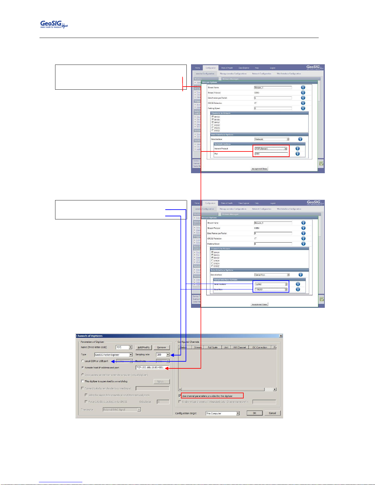
GMSplus User Manual
72 / 124 20.06.2017 / V21
GS_GMSplus_UserManual_V21
Adjust the settings according to chapter 10.4. Carefully select the settings in the Port Configuration.
If you want to stream over Ethernet, choose TCP/IP and TCP (Server).
Main Menu | Stream | Port
A) Communication port ... TCP/IP
C) Protocol ............. TCP (Server)
E) Network port ......... 4001 (0xFA1)
If you want to stream over the SERIAL port on the front of the instrument, choose ttyS03.
Main Menu | Stream | Port
A) Communication port ... ttyS03
B) Baud rate ............ 115200
Open GeoDAS and go to the menu Settings Channels of Digitizers… The following window
appears:
Figure 57. Channels of Digitizers
Adjust the Name, choose any three-letter code for the data stream
Select as Type the GeoSIG Packet Digitizer
Press Add/Modify
Page 73
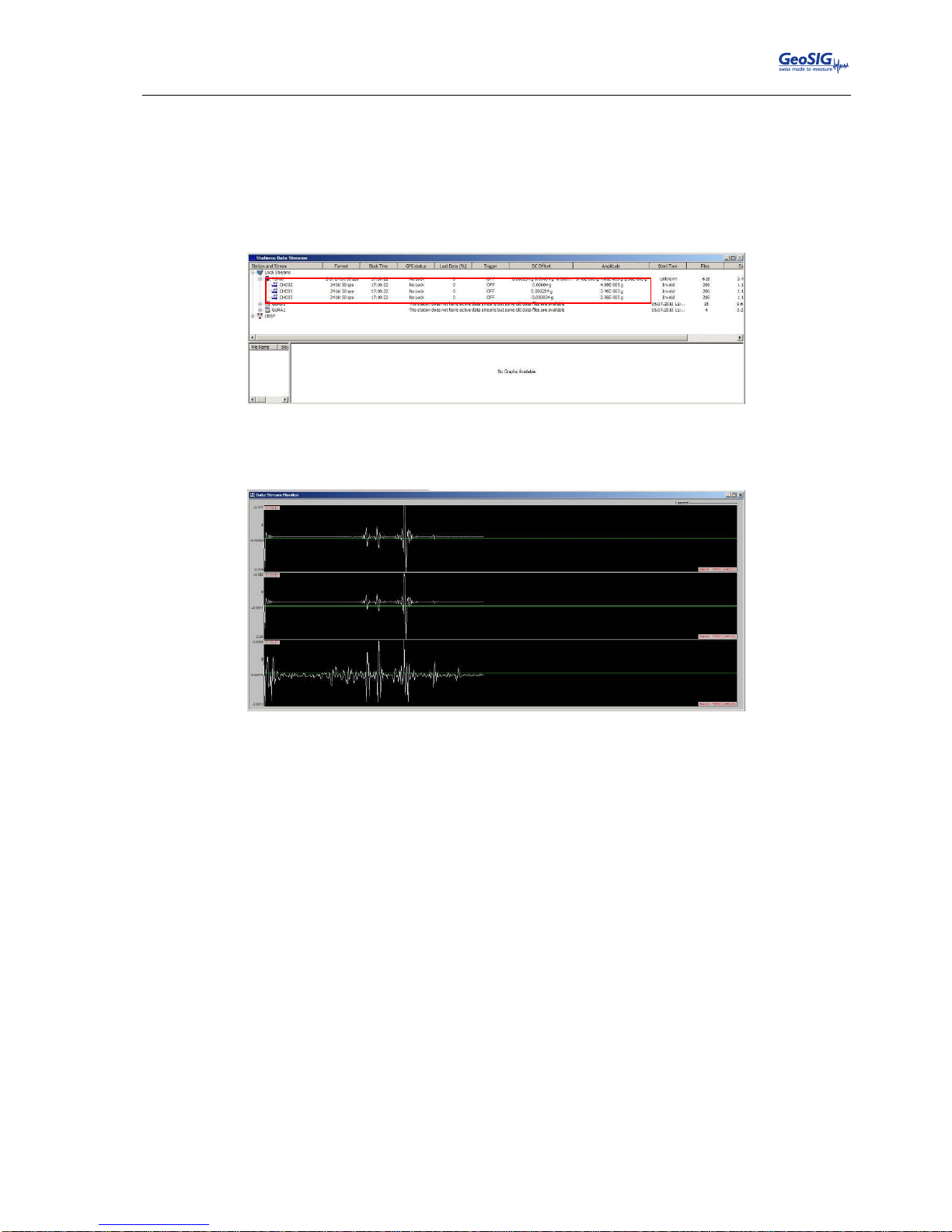
GMSplus User Manual
20.06.2017 / V21 73 / 124
GS_GMSplus_UserManual_V21
Make sure the selected Sample rate is the same as in the instrument.
Choose either the Local COM port (if connected over RS-232) or the Remote host IP address
and port (if connected over Ethernet). The instrument’s IP must be known.
Check the flag Use channel parameters provided by the digitizer.
Press OK.
After a restart of GeoDAS, the window Stations: Data Streams appears:
Figure 58. Stations: Data Streams
To view the data make a right click on the station name (here TST00) and select Data Monitor
Figure 59. Data stream window
Page 74
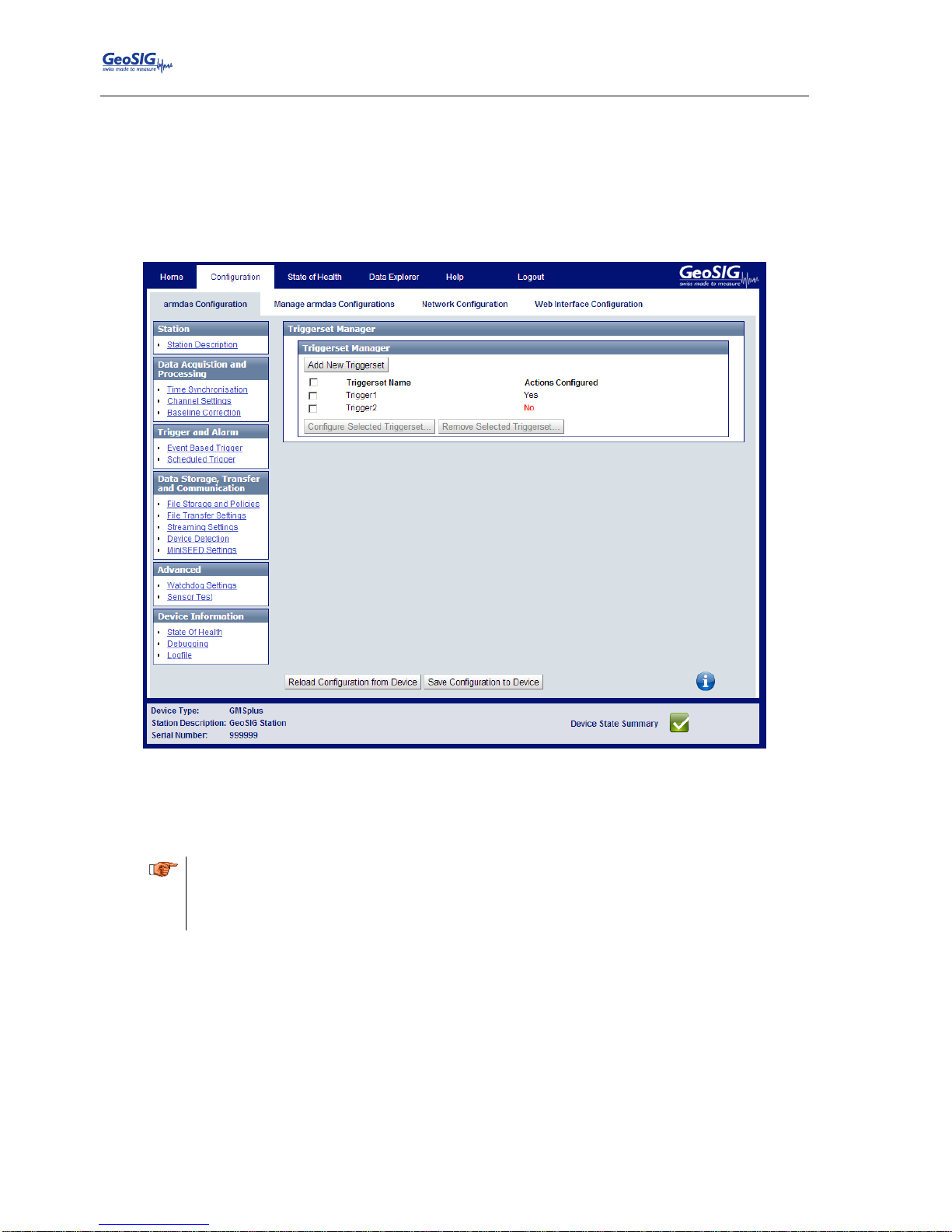
GMSplus User Manual
74 / 124 20.06.2017 / V21
GS_GMSplus_UserManual_V21
10.5. Trigger Settings
The instrument allows having several triggers with independent sources in parallel.
10.5.1. In the Web Interface or by GeoDAS
Go to Configuration armdas Configuration Event Based Trigger
Figure 60. Trigger Settings
Add new trigger set by the button Add New Triggerset. Trigger sets can be removed again by
Remove.
To edit a trigger set press the button Edit and adjust the parameters in the pop-up window. See
Table 13 for additional information.
a
In case a trigger is existing, but no action (such as recording the trigger, sending out an SMS or
activating a relay) is defined the “Action Configured” field in the trigger overview will indicate
that this is the case with a red “No” as this setup usually makes no sense. An example of such
a situation can be seen in Figure 6060 for Trigger 2.
Page 75
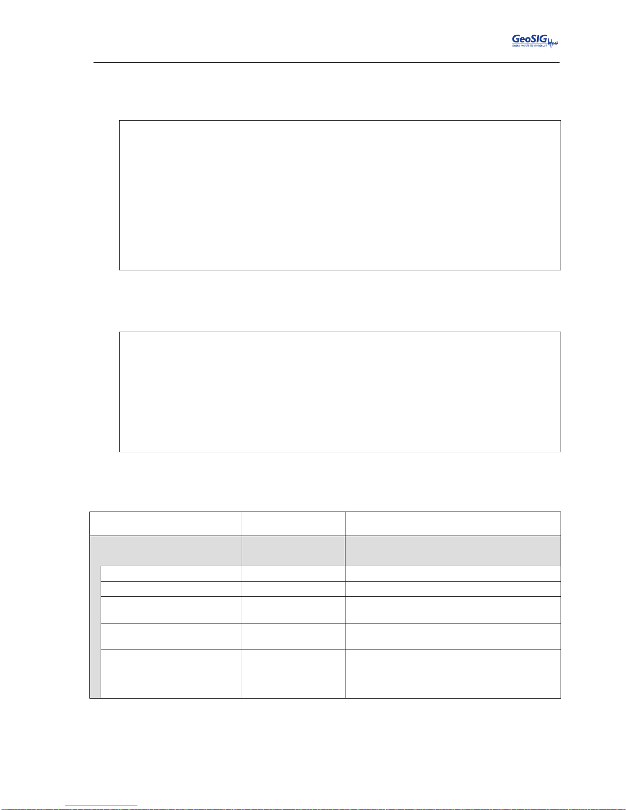
GMSplus User Manual
20.06.2017 / V21 75 / 124
GS_GMSplus_UserManual_V21
10.5.2. Via Local Serial Console
Press ‘G’ to select the Number of Trigger Sets
Main Menu
A) Station description ............. Demo GMSplus
B) Station code .................... DEMO
C) Location description ............ Switzerland
D) Seismic network code ............ CH
E) Number of Channels .............. 3
F) Number of Output Streams ........ 1
G) Number of Trigger Sets .......... 1
H) Number of Preset Triggers ...... 0
I) Channel Parameters .............. ->
J) Stream Parameters ............... ->
K) Trigger Parameters .............. ->
M) File Storage and Policy ......... ->
N) Communication Parameters ........ ->
O) Miscellaneous Parameters ........ ->
Press ‘K’ to get to the Trigger Parameters menu to adjust the settings of the triggers. The following menu
appears. In case the number of trigger sets is set to ‘0’ this menu can not be selected.
Main Menu | Triggerset
A) Triggerset name ....................................... Trigger1
B) Event recording ....................................... No
D) Alarm activation ...................................... No
E) SMS Alarm Configuration ............................... No
I) Trigger time frame, sec ............................... 3 (0x03)
K) Monitored channels .................................... 3
L) Trigger settings ...................................... ->
O) Be a source of network triggers (received from LAN) ... No
P) Activate on network triggers (received from LAN) ...... No
Q) Be a source of network triggers (Interconnection) ..... No
R) Activate on network triggers (Interconnection) ........ No
Each trigger set can be adjusted according to your wishes. To change the trigger set press ‘+’ or ‘-‘.
The following parameters can be adjusted:
Triggerset name
User selectable
Name of the trigger set
Event recording
Yes
No
An event file will be recorded on a trigger
No event file will be recorded on a trigger
Pre-Event
User selectable
Pre-Event time, seconds
Post-Event
User selectable
Post-Event time, seconds
Max. event duration, sec
User selectable
Maximum duration of an event in seconds. After
this time, an event file will be closed
Stored channels
User selectable
Number of channels, which should be stored
into an event file in case of a trigger
List of stored channels
User selectable
Depending on the number of stored channels
different sources can be selected. ‘+’ and ‘-‘ can
be used to change the channel, the source can
be selected by pressing ‘A’
Page 76
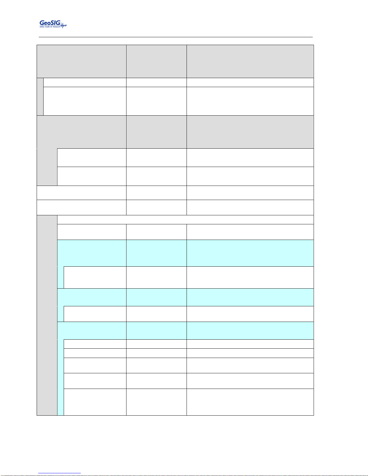
GMSplus User Manual
76 / 124 20.06.2017 / V21
GS_GMSplus_UserManual_V21
Alarm activation
(Only visible in case alarm relay
card is installed)
Yes
No
An alarm relay will be activated on a trigger
No alarm relay will be activated on a trigger
This option has an effect only in case the
instrument has internal alarm relays
Alarm output to activate
AL1, AL2, AL3, AL4
Select alarm relay
Alarm deactivation delay
User selectable
Time in seconds the alarm relay deactivates
again after the signal falls below the trigger
threshold. Can be compared to the post event
time for the recording
SMS Alarm Configuration
Yes
No
An SMS will be sent upon a trigger
No SMS will be sent upon a trigger
This option is available only in case an external
cellular modem is connected to the instrument.
SMS Alarm
Configuration
Number of Recipients
User selectable
The number of recipients of the SMS alarm can
be selected
Recipient
User selectable
Phone number of the recipient. Use numbers
only, no ‘+’ or any other character allowed
Trigger time frame, sec
User selectable
See chapter 10.5.5 for details
Monitored channels
User selectable
Number of channels which will be monitored by
the selected trigger set
Trigger settings
To go through the monitored channels press ‘+’ or ‘-‘.
Assigned channel
name
User selectable
Trigger filter
Yes
No
Trigger filter is used as defined under Filter
Parameters
Trigger filter is not used
Filter parameters
User selectable
One can select a filter type: Low, High and
Bandpass, order of the filter and corner
frequency(ies)
Level Trigger
Yes
No
Level trigger is enabled
Level trigger is disabled
Threshold
User selectable
As soon the data is above the configured
threshold the trigger is activated
STA/LTA Trigger
Yes
No
STA/LTA trigger is enabled
STA/LTA trigger is disabled
STA time frame
User selectable
Length of STA time window, seconds
LTA time frame
User selectable
Length of LTA time window, seconds
STA/LTA trigger
ratio
User selectable
As soon the data is above the configured
STA/LTA ratio the trigger is activated
STA/LTA detrigger
ratio
User selectable
As soon the data is below the configured
STA/LTA ratio again the trigger is deactivated
Clamp LTA during
event
Yes
No
The LTA value will not be updated during the
event
The LTA value will be updated during the event
Page 77
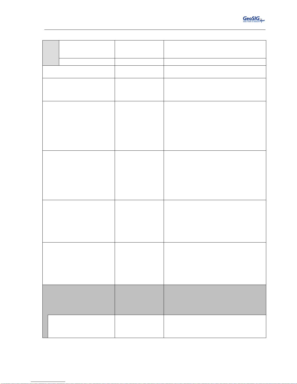
GMSplus User Manual
20.06.2017 / V21 77 / 124
GS_GMSplus_UserManual_V21
Min. level exceedance
User selectable
The threshold or STA/LTA ratio has to be
exceeded at least for the configured time in
seconds to active the trigger
Channel trigger weight
User selectable
See chapter 10.5.4 for details
Stored channels
User selectable
Number of channels, which should be stored
into an event file in case of a trigger
List of stored channels
User selectable
Depending on the number of stored channels
different sources can be selected. Use ‘+’ and ‘-‘
to change the channel, and select the source by
pressing ‘A’.
Be a source of network
triggers (received from LAN)
Yes
No
In case the instrument is interconnected over
LAN with other instruments:
All the other instruments will be alerted due to
the trigger of this instrument.
Other instruments will not be alerted due to the
trigger of this instrument.
A master instrument must be defined to use this
functionality. See chapter 10.5.6 for details.
Activate on network triggers
(received from LAN)
Yes
No
In case the instrument is interconnected over
LAN with other instruments:
The instrument will trigger if it receives an alert
from the LAN.
The instrument will not trigger if it receives an
alert from the LAN.
A master instrument must be defined to use this
functionality. See chapter 10.5.6 for details.
Be a source of network
triggers (Interconnection)
Yes
No
In case the instrument is interconnected over
the RS-485 interconnection network with
other instruments:
All other instruments will be alerted if there is a
trigger of this instrument.
Other instruments will not be alerted if there is a
trigger of this instrument.
Activate on network triggers
(Interconnection)
Yes
No
In case the instrument is interconnected over
the RS-485 interconnection network with
other instruments:
The instrument will trigger if it is alerted over the
interconnection network.
The instrument will not trigger if it is alerted over
the interconnection network.
Event processing
None
PGM Parameters
No event processing will be done
Peak ground motion parameters will be
calculated in case of an event and will be sent
to the server if configured according to chapter
10.7
Max. summary interval
User selectable
The PGM parameters will be sent after an
earthquake record has been completed or after
the defined time in seconds, whichever comes
first.
Table 13. Trigger configuration menu structure
Page 78

GMSplus User Manual
78 / 124 20.06.2017 / V21
GS_GMSplus_UserManual_V21
10.5.3. STA/LTA trigger
The STA/LTA (Short Time Average/Long Time Average) ratio trigger computes the short term and long term
averages of the input (sensor) signal. When the STA exceeds a pre-selected multiple of the LTA (STA/LTA
ratio), the instrument begins to record data. The advantage of this trigger type is that the trigger sensitivity
adapts to the seismic background signal. With an increasing noise level the trigger sensitivity decreases. The
probability of having a false trigger due to noise will be minimised if a long STA averaging time is selected.
Obviously, the STA should not be chosen longer than the shortest event of interest. In addition, the STA
should be shorter than the pre-event time. If not, the initial portion of an event may not be recorded. During
the steady state of the system, the STA and the LTA will be nearly equal. The shorter STA averaging period,
the more quickly it will change with the input.
10.5.4. Trigger Weight
To activate a trigger the total trigger weight must be equal or bigger than 100%. By default all channels have
a weight of 100%, which means if a threshold is exceeded on one channel only, then the trigger is activated.
If the trigger weight were reduced on all channels to 50%, then at least on two channels the threshold would
have to be exceeded to reach 100% (50% + 50%) and activate the trigger. See Figure 61 for details.
10.5.5. Trigger Time Frame
Depending on the settings, it can be that threshold must be exceeded on two or more channels to activate
the trigger (see chapter 10.5.4 for details). The time of the threshold-exceedances might be slightly different
on the channels, especially if two sensors are connected and installed on different places. To make sure that
even due to this time difference the trigger is working a trigger time frame can be defined. See Figure 61 for
details.
Page 79
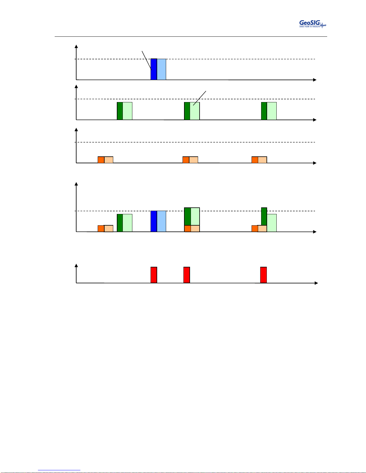
GMSplus User Manual
20.06.2017 / V21 79 / 124
GS_GMSplus_UserManual_V21
Figure 61. Overview of trigger weight and trigger time frame
10.5.6. Trigger Interconnection over LAN
If there are several instruments in the same LAN, they can be interconnected over Ethernet for common
triggering.
One instrument has to be set up as a master, whereas all other instruments are like slaves, sending the
trigger alarms to the master instrument. The master instrument then distributes the trigger alarm to all slaves.
All the communication between the data server and the slave instruments will go via the master instrument.
This means that the master instrument will download the requests first and forward it to the appropriate slave
instrument. On the other hand, the slave instruments will upload all the files to the master, which will upload
it to the data server.
100 %
100 %
100 %
100 %
X Y Z
Trigger time frame
Total Trigger Weight
ON
OFF
Trigger
Threshold exceeded
Page 80
GMSplus User Manual
80 / 124 20.06.2017 / V21
GS_GMSplus_UserManual_V21
10.5.6.1. Setup of the Master Instrument
Press ‘K’ to enter the menu Communication Parameters and activate the Server mode by pressing
‘H’
Main Menu
A) Station description ............. Demo GMSplus
B) Station code .................... DEMO
C) Location description ............ Switzerland
D) Seismic network code ............ CH
E) Number of Channels .............. 3
F) Number of Output Streams ........ 1
G) Number of Trigger Sets .......... 1
H) Number of Preset Triggers ...... 1
I) Channel Parameters .............. ->
J) Stream Parameters ............... ->
K) Trigger Parameters .............. ->
L) Parameters of Preset Triggers ... ->
M) File Storage and Policy ......... ->
N) Communication Parameters ........ ->
O) Miscellaneous Parameters ........ ->
a
To alter the settings in the Web Interface go to Configuration armdas Configuration
File Transfer Settings and Enable the flag Act as Server. Then just do the steps described
below in the GUI of the Web Interface
Specify the Port of incoming connections and adjust the number of slaves in the parameter Number
of clients. Write down the Port of incoming connections (use 3456 as default) and the IP of the
instrument, as they are used again during the configuration of the slave instruments.
Main Menu | Communication
A) Contact remote servers ............. Yes
B) Number of servers .................. 1
C) Time interval, sec ................. 10 (0x0A)
D) Maximum files per session .......... 10 (0x0A)
E) Connect if there are new files ..... Yes
F) Connect by requests from clients ... Yes
G) Server Parameters .................. ->
H) Server mode for other instruments... Yes
I) Port for incoming connections ...... 3456 (0xD80)
J) Secure authentication .............. No
K) Number of clients .................. 1
L) Clients Parameters ................. ->
M) Seedlink Server .................... Yes
N) Accept connections ................. Yes
The details of every slave instrument have to be filled out. Additionally make sure that the Data
forwarding and the Network triggers is set to Yes. To change the slave (client) instrument press ‘+’
or ‘-‘.
Main Menu | Communication | Client 1 of 2
A) Client IP Address ....... 0.0.0.0
B) Client serial number .... 000000
C) Transfer timeout, sec ... 20 (0x14)
D) Data forwarding ......... Yes
E) Network triggers ........ Yes
Page 81
GMSplus User Manual
20.06.2017 / V21 81 / 124
GS_GMSplus_UserManual_V21
10.5.6.2. Set up of the Slave Instruments
Press ‘K’ to enter the menu Communication Parameters
Main Menu
A) Station description ............. Demo GMSplus
B) Station code .................... DEMO
C) Location description ............ Switzerland
D) Seismic network code ............ CH
E) Number of Channels .............. 3
F) Number of Output Streams ........ 1
G) Number of Trigger Sets .......... 1
H) Number of Preset Triggers ...... 1
I) Channel Parameters .............. ->
J) Stream Parameters ............... ->
K) Trigger Parameters .............. ->
L) Parameters of Preset Triggers ... ->
M) File Storage and Policy ......... ->
N) Communication Parameters ........ ->
O) Miscellaneous Parameters ........ ->
a
To alter the settings in the Web Interface go to Configuration armdas Configuration
File Transfer Settings. Then follow the steps described below in the GUI of the Web Interface.
Press ‘A’ and change Contact remote servers to Yes if not already set and then go to Server
Parameters menu by pressing ‘G’.
Main Menu | Communication
A) Contact remote servers ............. Yes
B) Number of servers .................. 1
C) Time interval, sec ................. 10 (0x0A)
D) Maximum files per session .......... 10 (0x0A)
E) Connect if there are new files ..... Yes
F) Connect by requests from clients ... Yes
G) Server Parameters .................. ->
H) Server mode ........................ No
M) Seedlink Server .................... Yes
N) Accept connections ................. Yes
IP and Port from the master instrument must be adjusted in the field Server IP Address and Port
(use 3456 as default). Make sure the Network triggers are activated by putting Yes
Main Menu | Communication | Server
A) Server IP Address ...................... 192.168.10.02 (IP of the Master)
B) Protocol ............................... Custom
C) Port ................................... 3456 (0xD80)
H) Transfer timeout, sec .................. 40 (0x28)
I) Network triggers ....................... Yes
J) Connect through PPP link ............... No
O) Keep connected to the server ........... Yes
P) Server port for permanent links ........ 54204 (0xD3BC)
Select <A>...<Q>. <Esc> back to Main Menu | Communication
Page 82
GMSplus User Manual
82 / 124 20.06.2017 / V21
GS_GMSplus_UserManual_V21
10.5.6.3. Trigger Parameters for Master and Slave instruments
The following settings must be input on the master and the slave instruments.
Make sure on all instruments that the Number of Trigger Sets is not zero and then press ‘K’ to
enter the menu Trigger Parameters.
Main Menu
A) Station description ............. Demo GMSplus
B) Station code .................... DEMO
C) Location description ............ Switzerland
D) Seismic network code ............ CH
E) Number of Channels .............. 3
F) Number of Output Streams ........ 1
G) Number of Trigger Sets .......... 1
H) Number of Preset Triggers ...... 1
I) Channel Parameters .............. ->
J) Stream Parameters ............... ->
K) Trigger Parameters .............. ->
L) Parameters of Preset Triggers ... ->
M) File Storage and Policy ......... ->
N) Communication Parameters ........ ->
O) Miscellaneous Parameters ........ ->
a
To alter the settings in the Web Interface go to Configuration armdas Configuration
File Transfer Settings. Then follow the steps described below in the GUI of the Web Interface.
Configure the trigger set according to the description in chapter 10.5 and make sure that on all
instruments Be a source of network triggers (received from LAN) and Activate on network triggers
(received from LAN) is set to Yes
Main Menu | Triggerset
A) Triggerset name ....................................... Trigger1
B) Event recording ....................................... Yes
C) Record on network triggers only ....................... No
D) Alarm activation ...................................... No
E) SMS Alarm ............................................. No
G) Pre-Event, seconds .................................... 5 (0x05)
H) Post-Event, seconds ................................... 10 (0x0A)
I) Trigger time frame, sec ............................... 3 (0x03)
J) Max. event duration, sec .............................. 60 (0x3C)
K) Monitored channels .................................... 3
L) Trigger settings ...................................... ->
M) Stored channels ....................................... 3
N) List of stored channels ............................... ->
O) Be a source of network triggers (received from LAN) ... Yes
P) Activate on network triggers (received from LAN) ...... Yes
Q) Be a source of network triggers (Interconnection) ..... No
R) Activate on network triggers (Interconnection) ........ No
S) Event processing ...................................... None
If an instrument should trigger on network triggers, but not alarm the other instruments about an own trigger
(e.g. in a noisy area) the Be a source of network triggers (received from LAN) should be set to No.
If an instrument should alarm the other instruments over the LAN about a trigger, but not be activated on
network triggers, then Activate on network triggers (received from LAN) should be set to No.
Page 83
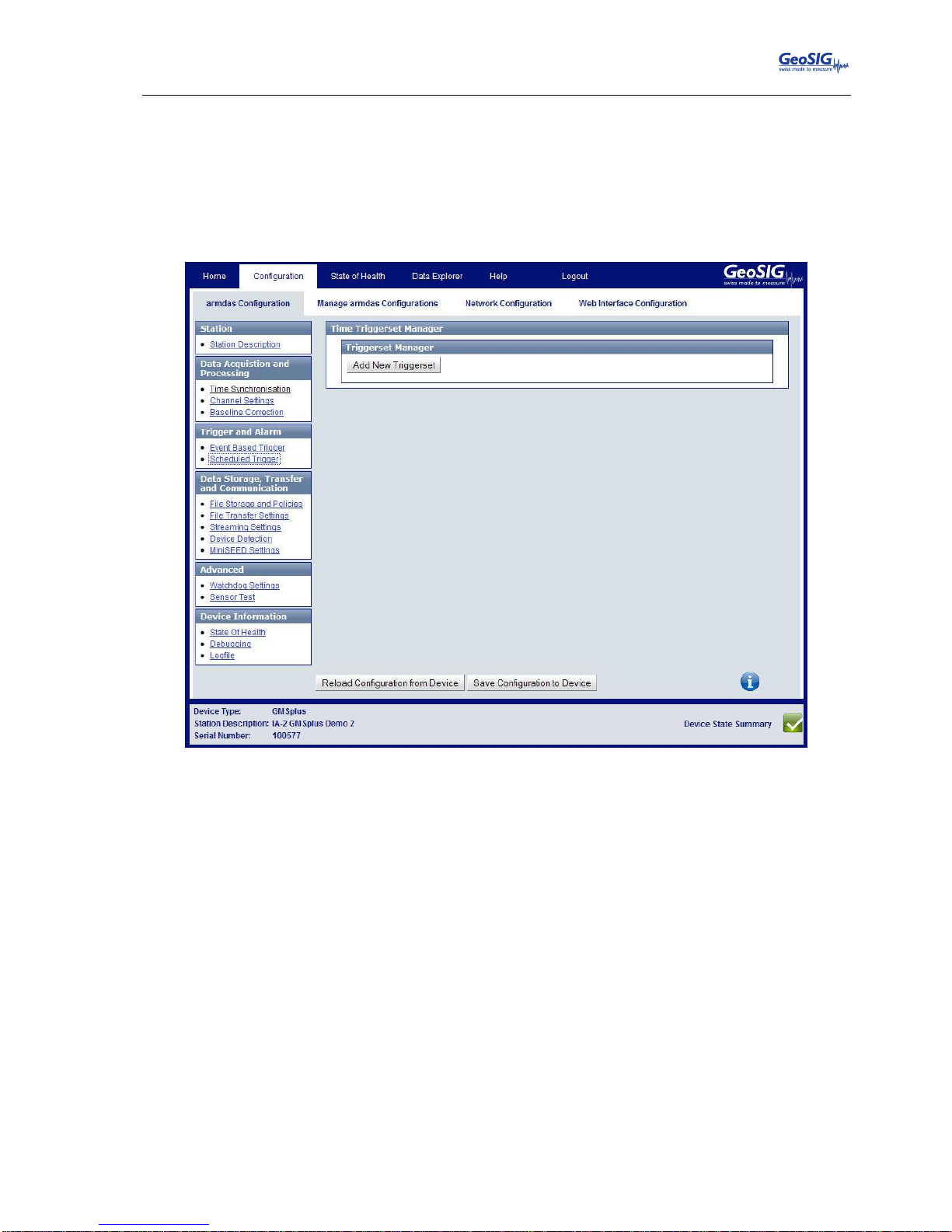
GMSplus User Manual
20.06.2017 / V21 83 / 124
GS_GMSplus_UserManual_V21
10.6. Preset Trigger Settings
The instrument allows having several predefined triggers, e.g. time triggers in parallel.
10.6.1. In the Web Interface or by GeoDAS
Go to Configuration armdas Configuration Scheduled Trigger
Figure 62. Preset Trigger Settings
Add new trigger set by the button Add New Triggerset. Trigger sets can be removed again by
Remove.
To edit a trigger set press the button Edit and adjust the parameters in the pop-up window. See
Table 14 for additional information.
Page 84
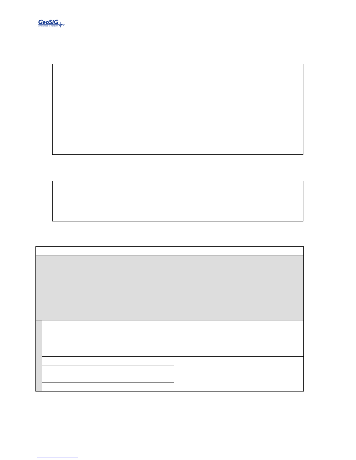
GMSplus User Manual
84 / 124 20.06.2017 / V21
GS_GMSplus_UserManual_V21
10.6.2. Via Local Serial Console
Press ‘H’ to select the Number of Preset Triggers
Main Menu
A) Station description ............. Demo GMSplus
B) Station code .................... DEMO
C) Location description ............ Switzerland
D) Seismic network code ............ CH
E) Number of Channels .............. 3
F) Number of Output Streams ........ 1
G) Number of Trigger Sets .......... 1
H) Number of Preset Triggers ...... 1
I) Channel Parameters .............. ->
J) Stream Parameters ............... ->
K) Trigger Parameters .............. ->
L) Parameters of Preset Triggers ... ->
M) File Storage and Policy ......... ->
N) Communication Parameters ........ ->
O) Miscellaneous Parameters ........ ->
Press ‘L’ to get to the Parameters of Preset Triggers menu to adjust the settings of the preset
triggers. The following menu appears only if the number of preset triggers is higher than ‘0’.
Main Menu | TimeTableTrigger
A) Preset trigger name .......... Trigger1
B) First trigger type ........... After Startup
H) Duration, seconds ............ 30 (0x1E)
I) Total number of triggers ..... 1 (0x01)
O) Stored channels .............. 1
P) List of stored channels ...... ->
Each trigger set can be adjusted according to your wishes. To change the preset trigger set press
‘+’ or ‘-‘. The following parameters can be adjusted:
Preset trigger name
User selectable
Name of the preset trigger set
First trigger type
There are several possible predefined triggers to choose
Manual Trigger
After Event
After Startup
Date and Time
A trigger is activated/stopped by the user
command TRIGGERNOW/STOPTRIGGER sent
either from the console or remotely from a server
A trigger is activated after recording of any event
file
First trigger is activated after the instrument startup
First trigger is activated at the defined date/time
Total number of triggers
User selectable
After reaching the configured number of triggers
the preset trigger will not be activated anymore
Delay after event
User selectable
If After Event is selected, then the time between
the end of the event to the beginning of the
activation of the preset trigger can be configured
First trigger time, year
User selectable
Date and time of the first trigger
First trigger time, day
User selectable
First trigger time, hour
User selectable
First trigger time, minute
User selectable
Page 85
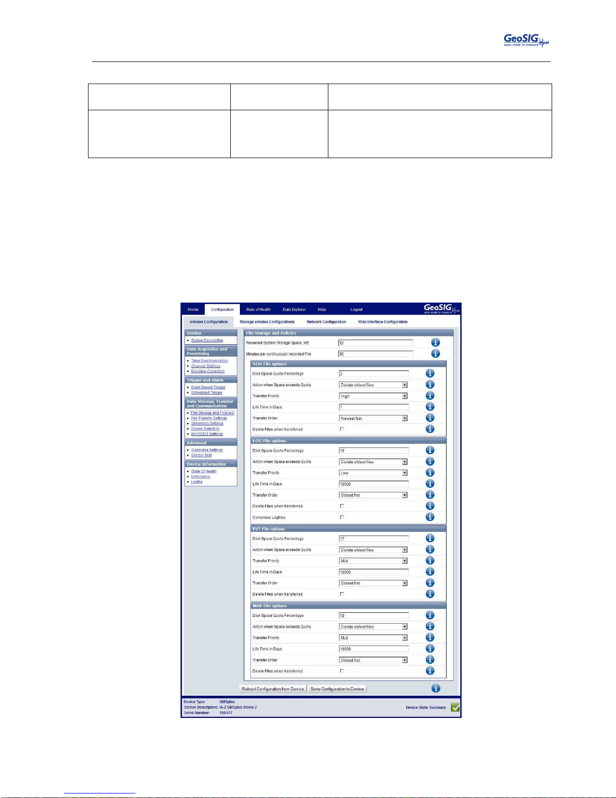
GMSplus User Manual
20.06.2017 / V21 85 / 124
GS_GMSplus_UserManual_V21
Stored channels
User selectable
Number of channels which should be stored into
an event file in case of a trigger
List of stored channels
User selectable
Depending on the number of stored channels
different sources can be selected. Use ‘+’ and ‘-‘ to
change the channel; select the source by pressing
‘A’.
Table 14. Preset trigger configuration menu structure
10.7. File Storage and Policy
It can be configured in the instrument how all the files should be treated.
10.7.1. In the Web Interface or by GeoDAS
Go to Configuration armdas Configuration File Storage and Policies
Figure 63. File Storage Settings
Page 86
GMSplus User Manual
86 / 124 20.06.2017 / V21
GS_GMSplus_UserManual_V21
Parameters for the following file types can be configured (see Filetypes in Table 15)
▪ SOH – State of health information and requested data files
▪ LOG – System log files
▪ TRG – Events and PGM files
▪ RBF – Ringbuffer files
▪ MAN – Scheduled manual recordings
▪ MSC – Miscellaneous files
See Table 15 for more information about the parameters which can be configured.
10.7.2. Via Local Serial Console
Main Menu
A) Station description ............. Demo GMSplus
B) Station code .................... DEMO
C) Location description ............ Switzerland
D) Seismic network code ............ CH
E) Number of Channels .............. 3
F) Number of Output Streams ........ 1
G) Number of Trigger Sets .......... 1
H) Number of Preset Triggers ...... 1
I) Channel Parameters .............. ->
J) Stream Parameters ............... ->
K) Trigger Parameters .............. ->
L) Parameters of Preset Triggers ... ->
M) File Storage and Policy ......... ->
N) Communication Parameters ........ ->
O) Miscellaneous Parameters ........ ->
To adjust the settings of the file storage, press ‘M’; the File Storage and Policy menu will appear.
Main Menu | File Storage
A) System reserved space, Mb ........ 12 (0x0C)
B) Length of one RB file, minutes ... 10 (0x0A)
C) SOH and requested data files ..... ->
D) System log files ................. ->
E) Events and PGM files ............. ->
F) Ringbuffer files ................. ->
G) Scheduled manual recordings ...... ->
H) Miscellaneous files .............. ->
• Parameters for the following file types can be configured (see Filetypes in Table 15)
▪ SOH – State of health information and requested data files
▪ LOG – System log files
▪ TRG – Events and PGM files
▪ RBF – Ringbuffer files
▪ MAN – Scheduled manual recordings
▪ MSC – Miscellaneous files
See Table 15 for more information about the parameters which can be configured.
Page 87
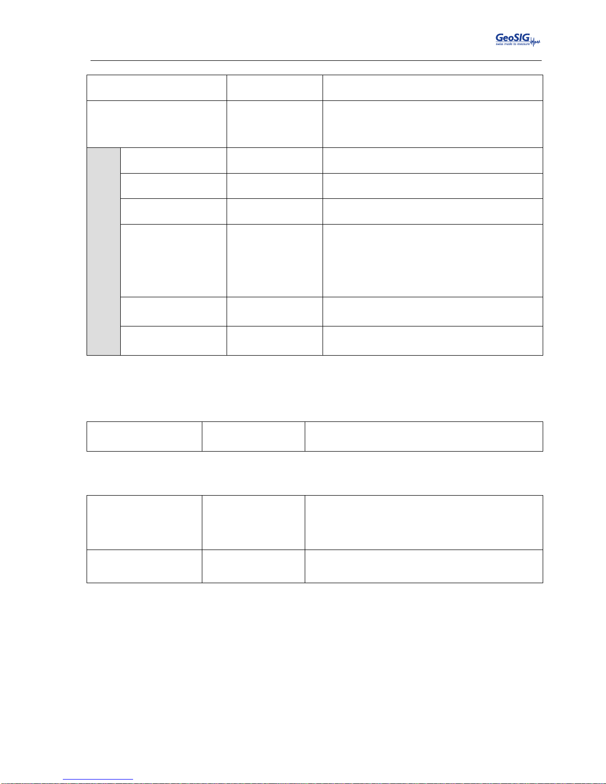
GMSplus User Manual
20.06.2017 / V21 87 / 124
GS_GMSplus_UserManual_V21
System reserved space
User selectable
Amount of memory reserved for the operating
system in [Mb]. Keep 12 Mb by default.
Length of one RB file
User selectable
Permanent data will be stored in ringbuffer files;
here the length of one ringbuffer file in minutes can
be specified. After this time the file will be closed
and a new one started.
Filetypes
Disk space quota
User selectable
Reserved memory on the SD/CF-Card for the SOH
files in [%]
If over quota
Delete oldest files
In case the reserved memory is full the oldest files
will be deleted first
Life time
User selectable
After the configured time in [days] the files will be
deleted from the SD/CF-Card
Transfer priority
Never Transfer
Low
Mid
High
Highest
In case a lot of files have to be transferred, the
priority of the file upload can be configured here. If
Never Transfer is configured, then no files will be
uploaded.
Transfer order
Newest first
Oldest first
Most recent files are transferred first.
Most old files are transferred first.
Delete transferred
Yes
No
Files will be deleted after upload to the server
Files will be not deleted after upload to the server
Table 15. File Storage and Policies menu structure
Additionally the system log files can be compressed. This can be separately enabled under the
menu point D) System log files:
Compress files
Yes
No
Files will be sent gzip-compressed (.gz)
Original text files will be sent (default)
State of health and event files have two more configuration options:
Transfer protocol
Standard (Custom)
HTTPS
Default option. This protocol also is used to transfer
any other types of files.
This option can be used to upload data files to the
HTTPS servers only. Downloads are not supported.
Directory for uploads
User selectable
Name of the directory on the HTTPS server where
uploaded files will be placed
Page 88
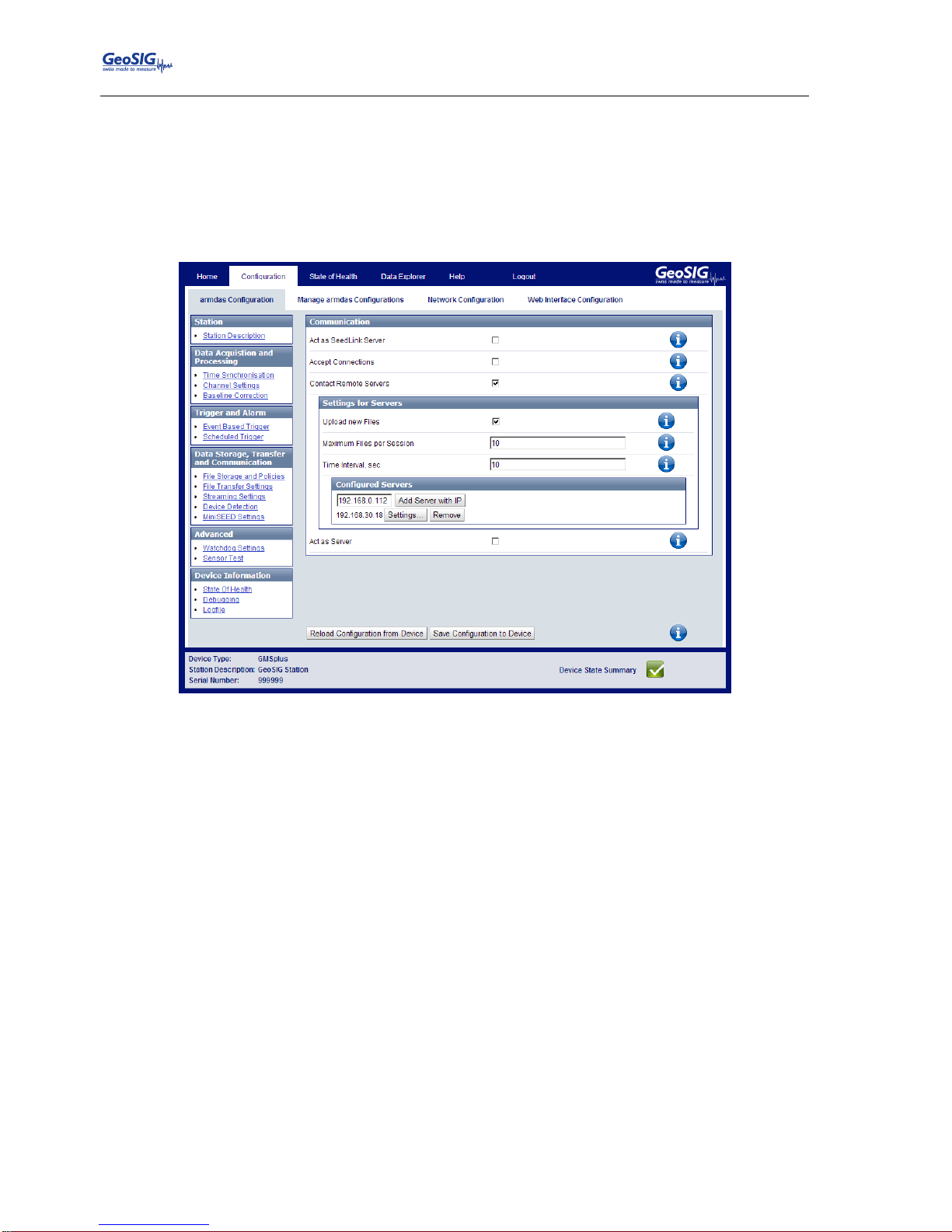
GMSplus User Manual
88 / 124 20.06.2017 / V21
GS_GMSplus_UserManual_V21
10.8. Communication Parameters
This chapter explains how to set up the server parameters.
10.8.1. In the Web Interface or by GeoDAS
Go to Configuration armdas Configuration File Transfer Settings
Figure 64. Server parameters
Tick the flag Contact Remote Servers to configure a connection to a remote server.
Add the IP of your server and press Add Server with Hostname. Servers can be removed again
by Remove.
Then press Settings… to adjust the parameters as shown in the Table 16.
In case the instrument should act as Server for other GMS-xx or GMS
plus
instruments, tick the flag
Act as Server and follow the steps as described in chapter 10.8.2.1
Page 89
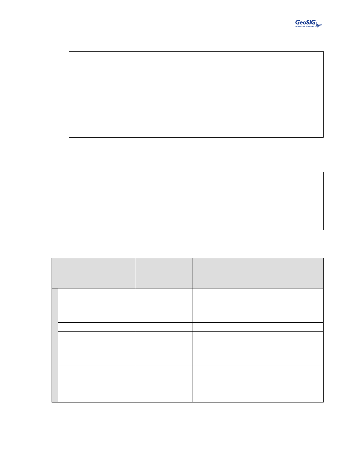
GMSplus User Manual
20.06.2017 / V21 89 / 124
GS_GMSplus_UserManual_V21
10.8.2. Via Local Serial Console
Main Menu
A) Station description ............. Demo GMSplus
B) Station code .................... DEMO
C) Location description ............ Switzerland
D) Seismic network code ............ CH
E) Number of Channels .............. 3
F) Number of Output Streams ........ 1
G) Number of Trigger Sets .......... 1
H) Number of Preset Triggers ...... 0
I) Channel Parameters .............. ->
J) Stream Parameters ............... ->
K) Trigger Parameters .............. ->
M) File Storage and Policy ......... ->
N) Communication Parameters ........ ->
O) Miscellaneous Parameters ........ ->
Press ‘N’ to get to the Communication Parameters menu to adjust the settings of the file storage.
The following menu appears:
Main Menu | Communication
A) Contact remote servers .............. Yes
B) Number of servers ................... 1
C) Time interval, sec .................. 20 (0x14)
D) Maximum files per session ........... 10 (0x0A)
E) Connect if there are new files ...... Yes
G) Server Parameters ................... ->
H) Server mode for other instruments ... No
M) SeedLink server ..................... Yes
N) Accept connections .................. Yes
The following parameters can be adjusted:
Contact remote servers
Yes
No
The instrument connects to the configured data
server(s).
The instrument does not connect to any data
servers.
Number of servers
User selectable
Number of data servers. If the instrument cannot
connect to the first data server it will connect to the
second data server; if this one is down it connects
to the third and so on. Scanning of servers stops
after first successful connection.
Time interval
User selectable
Interval of connection to data servers in seconds
Maximum files per session
User selectable
Maximum number of files, which will be uploaded
during one session. Although data servers support
concurrent connections, this parameter helps
distributing the load of data processing by the
server among several instruments.
Connect if there are new
files
Yes
No
Instrument connects to the server if there are new
files recorded and ready to be transmitted.
Instrument does not connect to the server if there
are new files. It just connects periodically as
defined with the parameter Time interval.
Page 90
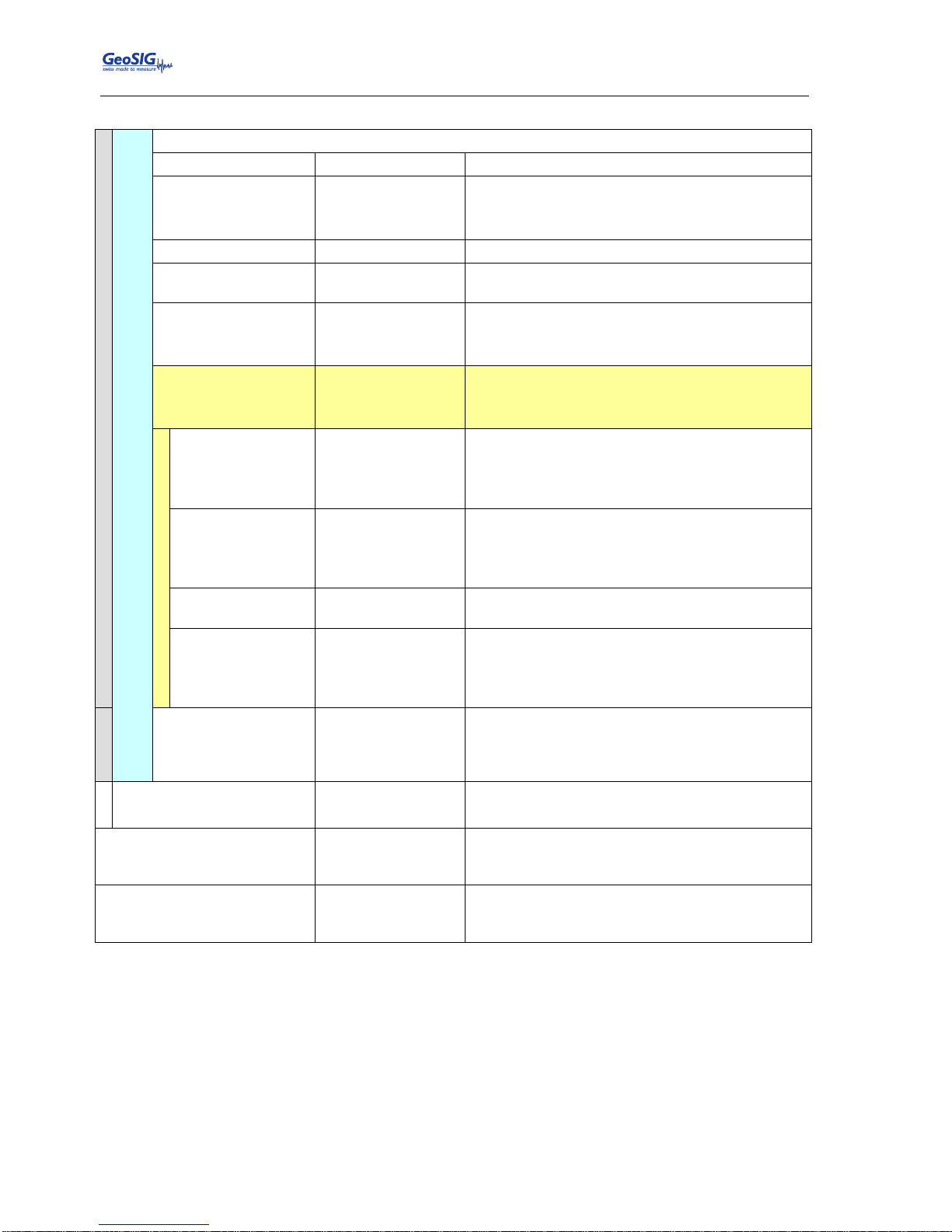
GMSplus User Manual
90 / 124 20.06.2017 / V21
GS_GMSplus_UserManual_V21
Server parameters
‘+’ and ‘-‘ can be used to change between the clients
Server IP Address
User selectable
IP address of the data server
Protocol
Custom
HTTPS
Default protocol of communication
This protocol can be selected only if you upload
SOH and/or EVT files to HTTPS servers.
Port
User selectable
Communication port of the data server
Transfer timeout
User selectable
Instrument gives up trying to contact the server
after the configured timeout in seconds.
Network triggers
Yes
No
Triggers are sent to the server for event detection
as described in chapter 14.2.
Triggers are not sent to the server.
Connect through
PPP link
Yes
No
Instrument connects to the data through PPP link.
Instrument does not connect to the data server
through PPP.
Use PPP only if
main link fails
Yes
No
Use PPP if no connection is possible to the data
server over Ethernet or Wi-Fi.
Use PPP for every connection, independent from
the main connection status.
Preferable PPP
link type
Internal analog
modem
External GPRS
modem
Use internal analog modem first
Use external cellular modem first
Number of failures
to give up
User selectable
Number of trials until giving up
Try alternate PPP
link on failure
Yes
No
Tries the alternative modem in case the first one
fails
Does not try further in case connection fails with
the first modem
Keep connected to
the server
Yes
No
If this flag is enabled, the instrument keeps the
channel to the server open. This allows configuring
the instrument through the web interface in
GeoDAS even over the Internet.
Server mode for other
instruments …
Yes
No
See chapter 10.8.2.1 for more details
SeedLink server
Yes
No
SeedLink server is enabled for all data channels,
and data streams can be received by any
SeedLink client from the instrument’s IP.
Accept connections
Yes
No
Allows GeoDAS to connect to the instrument.
Works only if the IP of the instrument is known and
reachable.
Table 16. Communication Parameters menu structure
Page 91
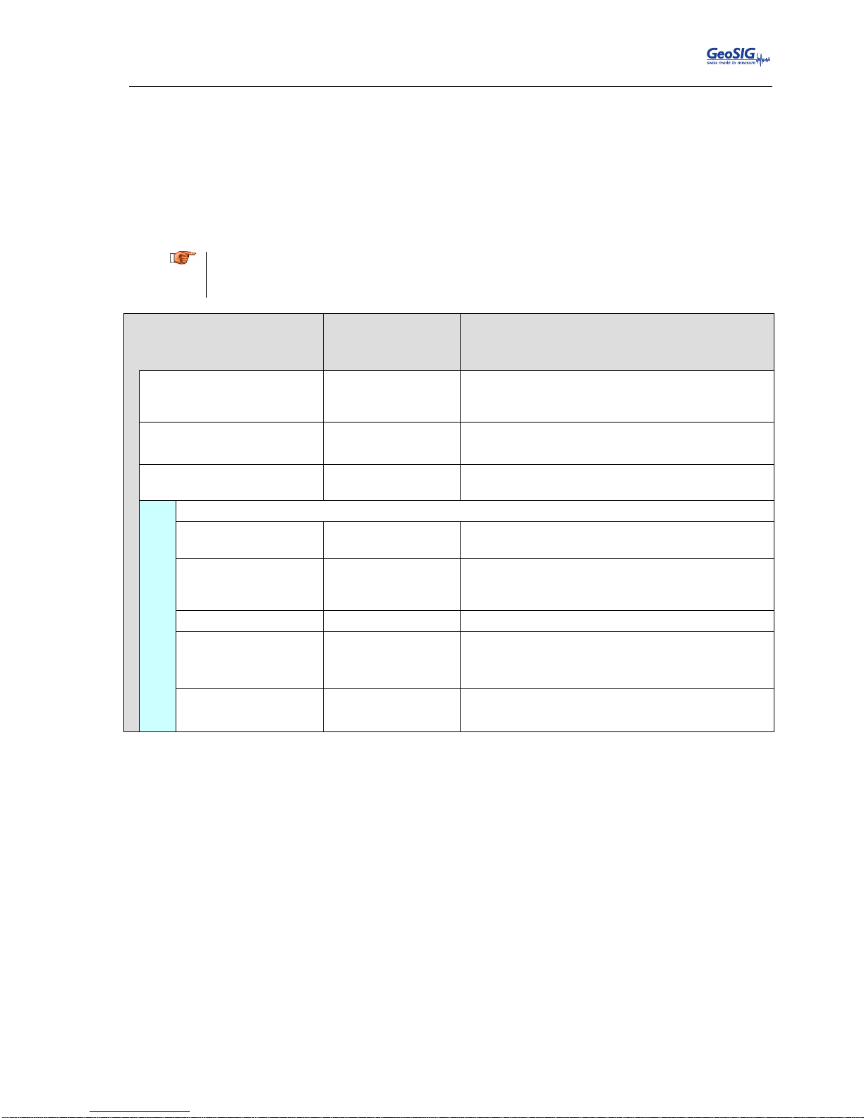
GMSplus User Manual
20.06.2017 / V21 91 / 124
GS_GMSplus_UserManual_V21
10.8.2.1. Instrument acts in the Server Mode
The instrument can be configured to act as a server. In this case other instruments can upload their files to
this instrument. The server-instrument can then forward the data to a main server by another communication
medium. For example, two instruments (clients) upload their files to the instrument-server, which forwards
the data to a GeoDAS server by the cellular modem.
The serial numbers and IPs of all client instruments must be configured in the server so that requests from
GeoDAS can be correctly forwarded.
a
This setup is not recommended, as it creates a big load for the server instrument. Special care
must be taken during design and setup. Whenever possible, all instruments shall have a direct
communication path to the GeoDAS server.
Server mode
Yes
No
The instrument acts as a data server for other
instruments.
The instrument does not act as a data server.
Port for incoming
connections
User selectable
Port for incoming connections. Other instruments
have to set the same port under Server
parameters.
Secure authentication
Yes
No
Secure authentication (SSL encryption) enabled
Secure authentication (SSL encryption) disabled
Number of clients
User selectable
Number of client instruments which upload data to
this instrument
Clients Parameters
‘+’ and ‘-‘ can be used to change between the clients
Client IP Address
User selectable
IP of the client instrument which connects to this
instrument
Client serial number
Custom
Serial number of the client instrument. Use 000000
to allow instruments with any serial numbers to
connect
Transfer timeout
User selectable
Network timeout in seconds
Data forwarding
Yes
No
Data from the data server will be forwarded to the
client instruments and the other way round.
Data will not be forwarded.
Network triggers
Yes
No
Network triggers will be sent to the server.
Network triggers will not be sent to the server.
Table 17. Server Parameters menu structure
10.8.3. Connection over PPP (Cellular Modem or Analog Phone Line)
If it is required to use a PPP link for communication of the instrument with the GeoDAS server, then the
configuration must be set accordingly in armdas (see chapter 10.8). It is also required to configure PPP for
selected ISP (Internet Service Provider). The ISP configuration settings are described in the following
chapters.
The GeoDAS server must have a real static IP-address (please, consult with ISP to obtain such a service). In
this example, 62.15.87.98 IP-address will be used for the GeoDAS server. GeoDAS server must be
configured as described in chapter 10.8.3.3.
Page 92
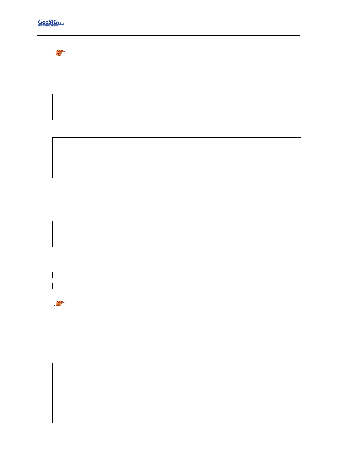
GMSplus User Manual
92 / 124 20.06.2017 / V21
GS_GMSplus_UserManual_V21
Automatic Detection of a Cellular Modem
a
This chapter can be skipped in case the PPP connection shall be done by the internal analog
landline modem.
Switch on the instrument by pressing and holding the POWER button for 2 seconds.
Press <Ctr> + ‘Z’ as soon the following message appears on the console to enter the test mode:
GMSplus s/n 100582. Firmware in the Linux image: 21.11.00
#################################################
###### Test and Initial Configuration Mode ######
#################################################
Press Ctrl+Z to enter the test mode.....
The following menu will appear (see chapter 11 for details):
--------------------------------------------------------------------------------------------
Level Shortcut Password Description
--------------------------------------------------------------------------------------------
User Ctrl+U None Basic operations only
Powerful User Ctrl+W None Also hardware options and pre-selected tests
Administrator Ctrl+A None Also manual tests and altering the FLASH memory content
--------------------------------------------------------------------------------------------
Your level [U/W/A] or press B to boot now:
By default, no passwords are set, so press ‘W’ to enter the Powerful User, and then ‘K’ to enter the
menu Instrument hardware parameters.
The instrument will start the automatic detection of an external cellular modem. Please wait 10
seconds till it is completed.
Loading hardware configuration...
Querying devices...
External modem power has been switched on
Please wait 10 seconds while the instrument tries to detect a cell modem
External modem power has been switched off
Depending on the connected cellular modem, one of the following messages appears:
Fast USB Cell Modem detected (SIMCOM_SIM5216E), IMEI = 359769031661413
Basic Serial Cell Modem detected (Teltonika TM2), IMEI = 353976014060325
.
a
Depending on the configuration, a combination of both is also possible, for example:
Fast USB Cell Modem detected (SIMCOM_SIM5216E), IMEI = 359769031661413
Basic Serial Cell Modem is configured but Fast USB Cell Modem is detected. Update
configuration (Y/N)?
If the modem is currently not present, but will be used later then the configuration can also be
adjusted manually in the following menu by pressing ‘H’. Besides the two types listed above, an
instrument may have also an internal 3G modem, which is also found automatically.
Hardware Configuration Menu
A) Number of sensors ........... 1
B) Sensor parameters ........... ->
C) Standard Wi-Fi module ....... No
Lantronix Wi-Fi module ...... No
Rack mounted slave board .... No
Wireless time sync module ... No
Internal analog modem ....... No
H) Cellular Modem .............. Fast USB Cell Modem
Alarm interface ............. No
Seismometer control ......... No
K) Interconnection interface ... Disabled
Leave the menu by pressing <ESC> and <Enter>, then ‘S’ to save the configuration.
Page 93
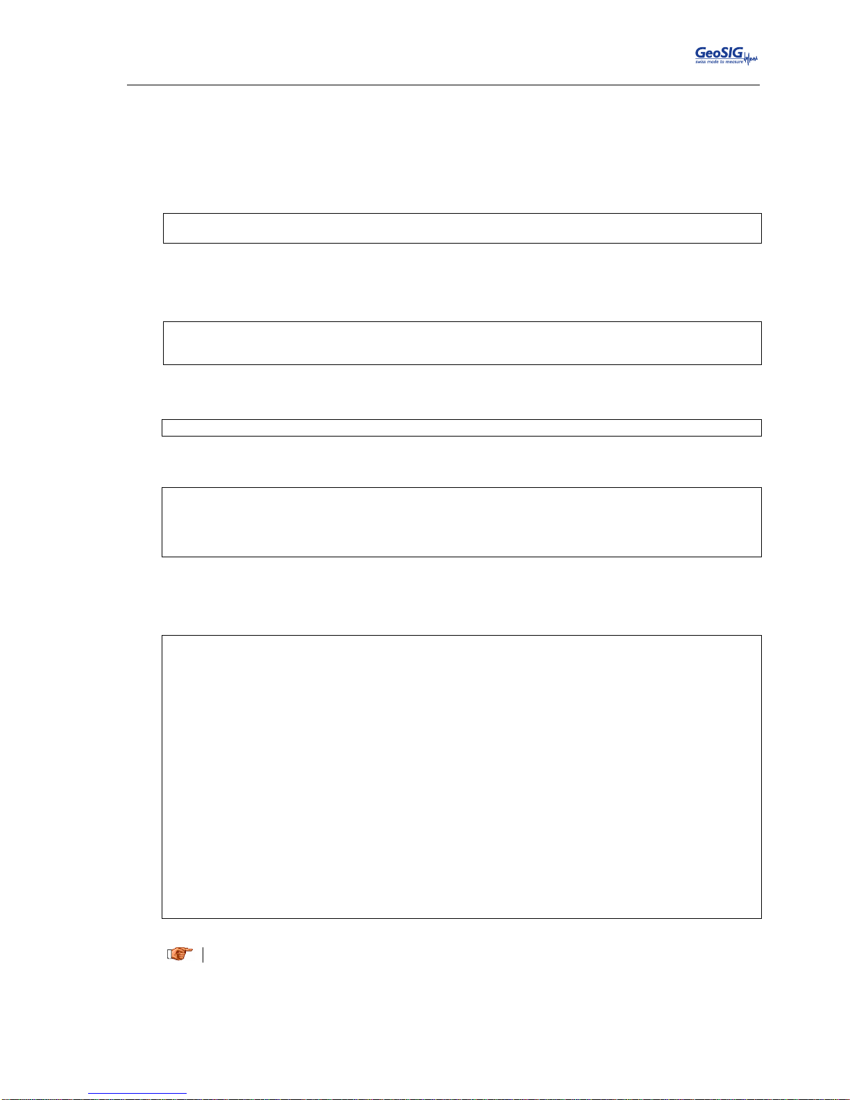
GMSplus User Manual
20.06.2017 / V21 93 / 124
GS_GMSplus_UserManual_V21
10.8.3.1. The ISP Configuration for PPP
To enter the APN, login and password of your mobile phone provider press ‘N’ to enter the menu
Network settings.
Press ‘N’ until the following message appears to adjust the ISP settings for the internal analog
phone line (only if installed):
---- PPP Communication ---Edit Analog Modem settings (Y/N)?:
Press ‘Y’ and enter the phone number, login and password given by your internet service provider.
Add a T in front of the number for tone dial, or a P for pulse dial.
Phone number of the service provider [T313001]:
Login [demo]:
Password [demo]:
Otherwise proceed to the following menu for the cellular modem settings.
Edit Cell Modem settings (Y/N)?
Enter the APN, login and password provided by our mobile phone provider.
APN of the service provider [gprs.swisscom.ch]:
Login []:
Password []:
Updating configuration...
PPP settings have been updated
By entering a blank space ‘ ‘ the field will be cleared.
Press <Enter> till the following menu appears and then press ‘5’ to start the instrument:
Bootloader Menu of the GMSplus s/n 100582
Access level: Powerful User
--- Flash Images and Boot Options --L - List flash images
Q - Reset instrument configuration to the user default
V - Reset instrument configuration to the factory default
5 - Boot now
X - Reboot the instrument
Y - Power off
--- Hardware Setup and Monitor --K - Instrument hardware parameters
N - Network settings
T - Battery installation dates
G – Signal strength of GSM network
--- Security --O - Set password
J - Reset all passwords
-->
a
In case of troubles with connection to the ISP, please contact the ISP support service.
Page 94
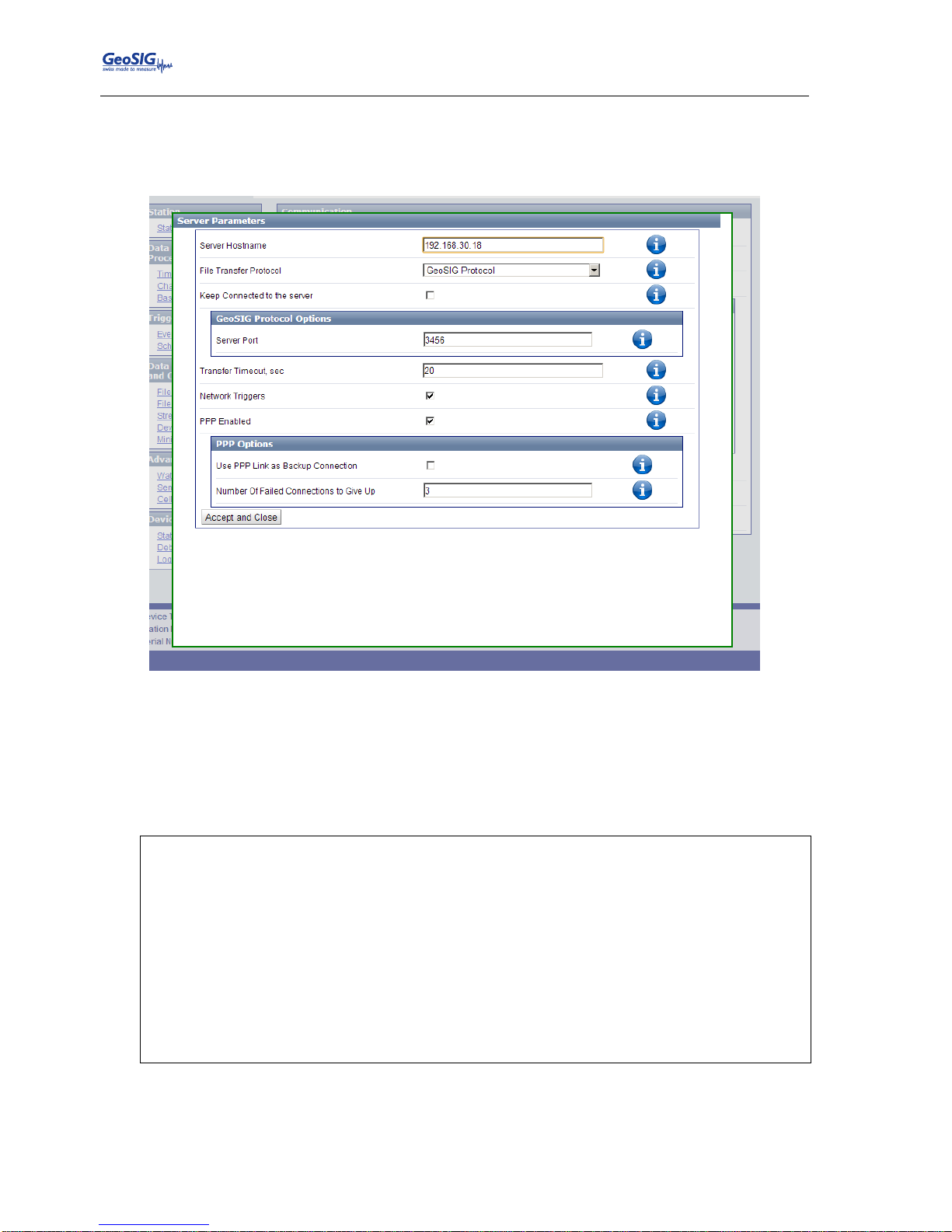
GMSplus User Manual
94 / 124 20.06.2017 / V21
GS_GMSplus_UserManual_V21
10.8.3.2. In the Web Interface or by GeoDAS
Go to Configuration armdas Configuration File Transfer Settings
Press the button Settings… under Configured Servers
Figure 65. Server parameters
Tick the flag PPP Enabled to configure a connection to a remote server via the external cellular or
internal analog modem.
10.8.3.3. armdas Configuration
To configure armdas, connect to instrument through serial console or from GeoDAS as described in chapter
10.
Main Menu
A) Station description ............. Demo GMSplus
B) Station code .................... DEMO
C) Location description ............ Switzerland
D) Seismic network code ............ CH
E) Number of Channels .............. 3
F) Number of Output Streams ........ 1
G) Number of Trigger Sets .......... 1
H) Number of Preset Triggers ...... 0
I) Channel Parameters .............. ->
J) Stream Parameters ............... ->
K) Trigger Parameters .............. ->
M) File Storage and Policy ......... ->
N) Communication Parameters ........ ->
O) Miscellaneous Parameters ........ ->
Page 95
GMSplus User Manual
20.06.2017 / V21 95 / 124
GS_GMSplus_UserManual_V21
Press 'N' to enter the Communication Parameters
Main Menu | Communication
A) Contact remote servers ............. Yes
B) Number of servers .................. 1
C) Time interval, sec ................. 60 (0x3C)
D) Maximum files per session .......... 10 (0x0A)
E) Connect if there are new files ..... Yes
G) Server Parameters .................. ->
H) Server mode ........................ No
M) SeedLink server ..................... Yes
N) Accept connections .................. Yes
Change Contact remote servers to Yes, then adjust the Server Parameters by pressing ‘G’
Main Menu | Communication | Server
A) Server IP Address ...................... 62.15.87.98
B) Protocol ............................... Custom
C) Port ................................... 3456
H) Transfer timeout, sec .................. 40 (0x28)
I) Network triggers ....................... No
J) Connect through PPP link ............... Yes
K) Use PPP only if main link fails ..... No
L) Preferable PPP link type ............... Internal analog modem
M) Number of failures to give up .......... 3 (0x03)
N) Try alternate PPP link on failure ...... Yes
O) Keep connected to the server ........... Yes
P) Server port for permanent links ........ 54204 (0xD3BC)
GeoDAS server IP address must be set as Server IP Address and port number for Port parameter
such as for server in GeoDAS configuration (see Figure 27).
Connect through PPP link should be Yes.
Preferable PPP link type can be Internal analog modem or External GPRS modem (depends
upon used modem type).
If the user wants to use two modems (analog and GSM) together, one of which is in a role of an
alternate link, then it is required to set Try alternate PPP link on failure to Yes. In this case, if the
preferred modem will fail after the Number of failures to give up, then alternate modem will be used
to establish link.
After these adjustments, exit from submenus by <ESC> key, save configuration with ‘C’ and restart
armdas by pressing ‘R’.
a
After the modem is powered it takes a while till it finds the network, therefore we recommend to
set the ‘Startup time for cell modem’ to 60 seconds.
Page 96

GMSplus User Manual
96 / 124 20.06.2017 / V21
GS_GMSplus_UserManual_V21
10.9. Miscellaneous Parameters
The Time synchronisation, State of Health files, messaging and debugging can be adjusted under this menu.
10.9.1. In the Web Interface or by GeoDAS
The parameters of this menu item are split up over several pages.
To adjust the time synchronisation, go to Configuration armdas Configuration Time
Synchronisation
To adjust the offset corrections settings, go to Configuration armdas Configuration
Baseline Correction
To adjust how many times the SOH information shall be sent, go to Configuration armdas
Configuration State of Health
To adjust the type and the number of the sensor test pulses, go to Configuration armdas
Configuration Sensor Test
To enable/disable the autodetection of Web Interface, go to Configuration armdas
Configuration Device Detection
To enable additional debug messages in the system log files, go to Configuration armdas
Configuration Debugging
To adjust, when the system log files shall be sent, go to Configuration armdas Configuration
Logfile
Adjust the parameters as shown in the Table 18.
Page 97

GMSplus User Manual
20.06.2017 / V21 97 / 124
GS_GMSplus_UserManual_V21
10.9.2. Via Local Serial Console
Main Menu
A) Station description ............. Demo GMSplus
B) Station code .................... DEMO
C) Location description ............ Switzerland
D) Seismic network code ............ CH
E) Number of Channels .............. 3
F) Number of Output Streams ........ 1
G) Number of Trigger Sets .......... 1
H) Number of Preset Triggers ...... 1
I) Channel Parameters .............. ->
J) Stream Parameters ............... ->
K) Trigger Parameters .............. ->
L) Parameters of Preset Triggers ... ->
M) File Storage and Policy ......... ->
N) Communication Parameters ........ ->
O) Miscellaneous Parameters ........ ->
Press ‘O’ to get to the Miscellaneous Parameters menu to adjust time synchronisation, offset
detection, and other settings. The following menu appears:
Main Menu | Miscellaneous
A) Offset detection time, sec ............... 10 (0x0A)
B) Offset correction time, sec .............. 0 (0x00)
C) Offset correction counts ................. 1 (0x01)
D) MiniSEED record length ................... 512
E) Extended MiniSEED format ................. Yes
F) Include SOH information in miniSEED ...... Yes
G) Include configuration in miniSEED ........ Yes
H) State of health .......................... ->
I) Test configuration ....................... ->
J) Messaging and debugging .................. ->
K) Time synchronization ..................... ->
L) Instrument configuration options ......... ->
M) Time for sending daily logfile, hour ..... 0 (0x00)
N) Time for sending daily logfile, minute ... 0 (0x00)
O) Keep modem always powered ................ No
Q) Startup time for cellular modem .......... 60 (0x3C)
S) Connect time for cellular modem .......... 60 (0x3C)
The following parameters can be adjusted:
Offset detection time
User selectable
Time in seconds, which the input values is measured
after startup to define the offset
Offset correction time
User selectable
During operation, the instrument calculates the offset
of each channel over the time defined under Offset
correction time and adds or subtracts the number of
counts defined under Offset correction counts to the
signal if there is any positive or negative offset
present. This procedure will be permanently
repeated, so over time any offset in the signal will be
corrected.
Offset correction counts
User selectable
MiniSEED record length
User selectable
Length of one data block inside the miniSEED file. In
most applications, the default value 512 shall be kept.
Extended MiniSEED format
No
Yes (default)
MiniSEED files do not include any additional
information. This option shall be used only if you face
any problems in reading extended format of
miniSEED files with your customized software.
MiniSEED files include configuration and state of
Page 98
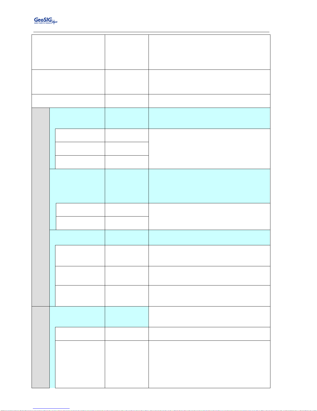
GMSplus User Manual
98 / 124 20.06.2017 / V21
GS_GMSplus_UserManual_V21
health information, which is encapsulated into the
blockettes 2000. When you open such files with
GeoDAS, there is no need to enter LSB factors and
units (see the chapter 14.4) as this information is
retrieved from files. This feature is supported from
GeoDAS version 2.21.
Include SOH information in
miniSEED
No (default) or
Yes
It is another way of including SOH information into the
miniSEED files: as an ASCII data channel named
SOH. This option is enabled only if Extended
miniSEED format is not used.
Include configuration in
miniSEED
No (default) or
Yes
Similar to the above: data channel CFG contains
configuration information in XML format.
State of health
SOH report type
None
Standard
No SOH file will be created
SOH files will be created and uploaded to the server
according to the settings in chapter 10.7
SOH reporting
interval , days
User selectable
Defines the interval between the SOH reports in days,
hours and minutes
SOH reporting
interval, hours
User selectable
SOH reporting
interval, minutes
User selectable
Time of the first SOH
report
Startup
Random
User defined
First SOH report will be created at startup
Time of the first SOH is random. This is to avoid all
instruments using the network at the same time.
First SOH report will be created at the user defined
time.
First SOH report
time, hours
User selectable
Defines the hour and minute of the first SOH report
First SOH report
time, minutes
User selectable
Activate alarm on
errors
Yes
No
Activates an alarm relay in case of an error
Alarm relay will not be activated in case of an error
Activate alarm
when system is
inactive
Yes
No
Alarm relay is activated in case armdas is not running
(e.g. during startup or after shutdown)
Alarm relay will not be activated
Error and
inactivity alarm
output
AL1, AL2, AL3,
AL4
Alarm relay which should be activated in case of an
error or armdas is not running
Activate alarm on
selected errors
only
No
Yes
Selected alarm relay is activated on all errors
Selected alarm relay is activated on selected errors
only. The errors can be selected by pressing ‘L’ to ‘T’
Test configuration
Type of periodic
sensor test
None
Pulse
No test pulse is generated
Test pulse is generated periodically and
automatically, depending on the following settings
Sensor test
interval, days
User selectable
Interval between two sensor tests
Activate alarms on
sensor test
Normal
Always
Never
Default parameter. The alarm is activated only if the
amplitude of a test file exceeds related trigger
thresholds.
Alarms are always activated, irrespective of the test
pulse amplitude.
Alarms are never recorded during test.
Page 99
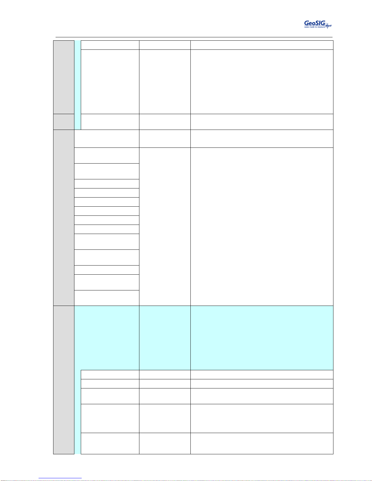
GMSplus User Manual
20.06.2017 / V21 99 / 124
GS_GMSplus_UserManual_V21
Record test files
Normal
Always
Never
Default parameter. The files are recorded only if the
amplitude of a test file exceeds related trigger
thresholds.
Data files are always recorded during test,
irrespective of the test pulse amplitude.
The files are never recorded during test.
Prefix for names
of test files
User selectable
Either CAL_ or TRG_
Messaging and debugging
Console messages
Yes
No
Enables console messages
Disables all console messages
Debug: memory
allocation
Yes
No
Enables or disables specific debug messages. These
are for service or advances users only.
Keep No by default.
Debug: system and
processes
Debug: flash memory
Debug: configuration
Debug: network links
Debug: data streams
Debug: data sources
Debug: ring buffers
Debug: event
triggers
Debug: time
synchronization
Debug: file manager
Debug:
cryptographic info
Debug: hardware
related info
Time Synchronization
Time source
RTC
GPS
NTP
AUTO
NET1PPS
RTC is not synchronizing itself to any source
RTC is synchronizing to the connected GPS
RTC is synchronizing to a NTP server
RTC synchronizes to NTP in case GPS is not
available
RTC is synchronizing to the 1PPS signal distributed
by the 433 MHz module or the interconnection
network.
NTP server 1
User selectable
IP of the primary NTP Server
NTP server 2
User selectable
IP of the secondary NTP Server
NTP server query
interval
User selectable
Interval time in seconds the NTP server is contacted
by the instrument
NTP requests in a
row
User selectable
Every time the instrument contacts the NTP server
the configured number of requests will be sent. For
service and advanced users only, do not change
the default value of ‘4’
NTP maximum
error
User selectable
Above this time in [seconds] the RTC will make a time
jump to the NTP time. Otherwise the time will be
tuned slowly. For service and advanced users
Page 100
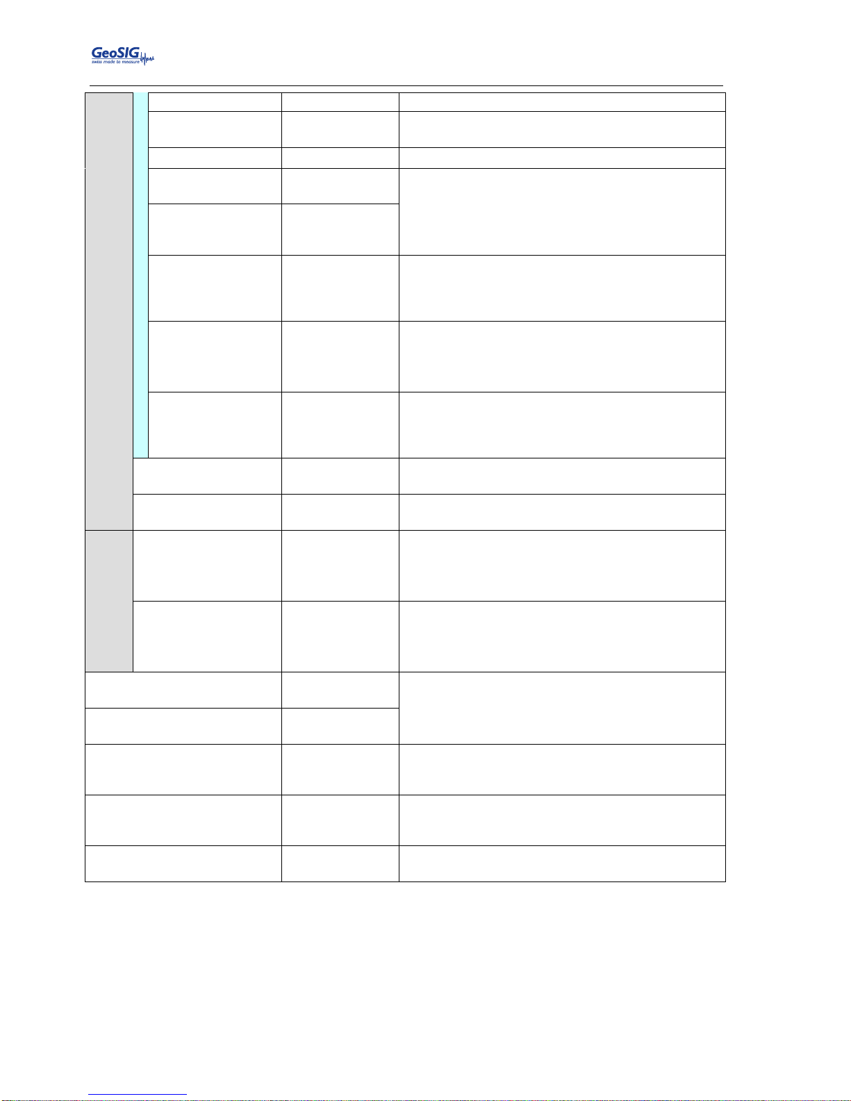
GMSplus User Manual
100 / 124 20.06.2017 / V21
GS_GMSplus_UserManual_V21
only, do not change the default value of ‘1’.
GPS reception
timeout, min
User selectable
If GPS signal is lost, after this time in [minutes] the
RTC will change its synchronization to NTP.
GPS check interval
in NTP mode, min
User selectable
If in the ‘Auto’ mode the RTC is synchronized to the
NTP, the instrument checks in the configured interval
whether the GPS is available again.
GPS check
duration in NTP
mode, sec
User selectable
RTC watchdog
timeout, sec
User selectable
Hardware watchdog timeout in seconds. The firmware
is supposed to reset watchdog within this time interval
at least once, otherwise the full hardware reboot will
be performed.
Send SOH upon
RTC status
change
Yes
No
In case RTC status changes, a SOH message will be
uploaded to the server.
No SOH message will be sent upon RTC status
change.
Offset to UTC,
minutes
User selectable
This parameter is used to make instrument stamping
data with a local time instead of UTC. Not
recommended if you plan to exchange data with other
networks of instruments.
WiSync transmission
interval, min
User selectable
If a 433 MHz WiSync module is installed, the radio
module is switched on in the user defined interval.
WiSync transmission
duty cycle
User selectable
Defines how long the 433 MHz WiSync module
remains enabled. In % of the defined interval.
Instrument configuration
options
Enable autodetection
of the instrument
Yes
No
Instrument can automatically be found by GeoDAS in
the LAN.
Instrument cannot automatically be found by
GeoDAS.
Configurable with a
browser
Yes
No
Web Interface is enabled and instrument can be
configured with the browser.
Web Interface is disabled.
Time for sending daily
logfile, hour
User selectable
If transfer is activated in chapter 10.7, at this time the
daily logfile will be sent to the server. Settings can be
adjusted to avoid all instruments sending the logfile at
the same time.
Time for sending daily
logfile, minutes
User selectable
Startup time for analog
modem
User selectable
Time in seconds required for the modem after turning
it ON to be fully operational and ready to
communicate
Startup time for cellular
modem
User selectable
Time in seconds required for the modem after turning
it ON to be fully operational, to be registered in the
cellular network and ready to communicate
Connect time for analog
modem
User selectable
Time in seconds required to establish the PPP link
 Loading...