

Page 1
geosat mobile wi-figeosat mobile wi-fi
geosat mobile wi-fi
geosat mobile wi-figeosat mobile wi-fi
User Manual
Page 2
INTRODUCTION
Thank you for purchasing the GEOSat Mobile Wi-Fi
Solution and welcome to the world of wireless
networking on the water. Now you can take advant age
of the growing number of HotSpots along the
waterways of the U.S. and Canada as well as the
islands of the Bahamas and the Caribbean.
As a systems integrator, GEOSat’ s engineers have
spent countless hours testing various configurations of
the mobile Wi-Fi hardware until they developed a
balanced package that delivers optimum performance
for mobile license-free local area network access.
Before you begin installation, remember that, with
the exception of your laptop or PC, the GEOSat
Mobile Wi-Fi Solution is sold as a complete package
only. The antenna, antenna cable and the radio/
amplifier are a balanced system. Changing any one of
these elements will jeopardize performance, void the
T erabeam warranty and could result in a possible FCC
violation.
ABOUT GEOSat WI-FI
NOTE: Optional
Ethernet Interface
Cables are available in
lengths up to 100 feet.
It is strongly
recommended that
you configure and test
the unit prior to
permanently mounting
the antenna or EC. It
is important that the
antenna be placed in
Fig. EC-1
forming such a test will avoid the necessity of
relocating the antenna and rerouting cables.
an unobstructed
location and within 25
feet of the EC. Per-
INSTALLATION
Read through this entire section to understand how
to install the hardware. To configure the EC, please
refer to the ‘Configuration’ section.
The GEOSat Mobile Wi-Fi Solution (EC) is a single
channel 802.1 1b compliant radio housed in a
weatherproof NEMA 4 rated outdoor enclosure. It
features an Ethernet Converter (EC-II) for use as a
CPE (the equipment necessary to obtain access to a
wireless network).
It is powered from an external 12 VDC source but it
will operate from a source of 1 1 to 14 VDC. An
integrated bidirectional amplifier provides increased
transmit power and receive signal sensitivity for the
longest possible range. The unit draws about 1.5 amps
peak.
The 28-bit WEP-Plus encryption, if enabled,
provides extra security above standard 802.1 1b WEP .
The EC will accommodate virtually an unlimited
number of client MAC addresses on each side of the
link.
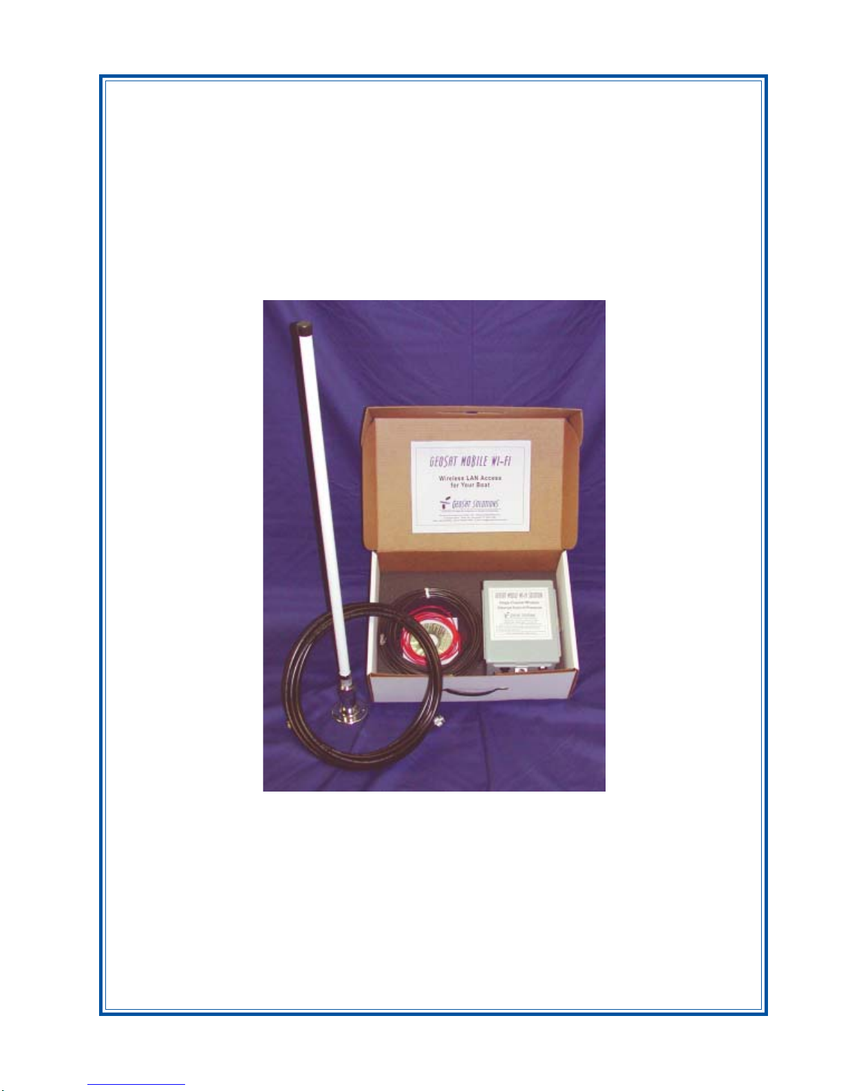
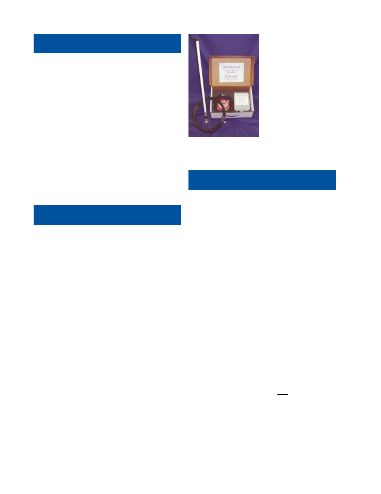
GEOSat Wi-Fi Kit Contents (Fig. EC-1)
1. The EC-AMP-12V radio and amplifier,
weatherproof outdoor enclosure.
2. DC Power cable - 10 feet with connector at one
end.
3. Outdoor Ethernet interface cable – 25 foot.
4. 10 dBi omni-directional marine antenna.
5. LMR 400 antenna cable – 25 foot.
6. CD-ROM with Windows - based Client Manager
software and documentation.
Perform the following procedures once you have
determined the optimal location for the EC:
1. Mounting the EC – Make sure the location
you selected will support the weight of the
box. Select mounting hardware that is
appropriate in size and that will support the
weight of the EC in heavy seas.
CAUTION: Make sure that the enclosure is
properly grounded for maximum lightning and
static protection.
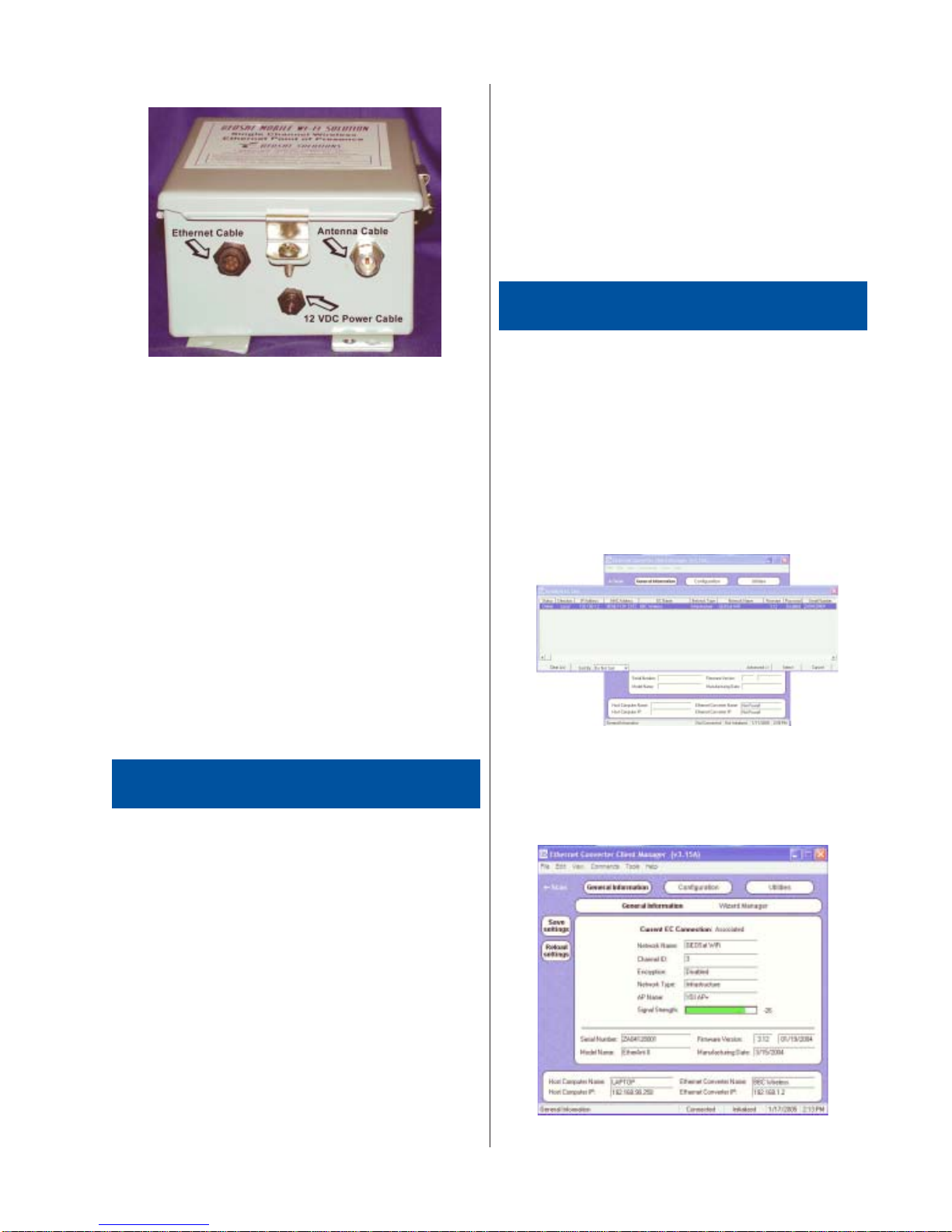
2. Plug the round connector of the outdoor
Ethernet cable into the jack on the bottom of
the EC, making sure the notch is correctly
aligned with the tab on the jack (Fig. EC-1),
then turn the round locking nut clockwise as
you push in until it securely fastens onto the
jack. Please verify that the round connector is
properly plugged into the jack of the EC
because it is possible to push it in the wrong
way if enough force is used. Damage to the
EC or the connector will not be covered by
the warranty .
3. Mount the supplied 10 dBi antenna securely
being certain that the LMR 400 antenna cable
can be run with no severe bends.
4. Connect one end of the antenna cable to the
antenna and the other end to the antenna
coupling on the bottom of the EC. (Fig. EC-2)
Page 3
Manager in Windows, insert the Wi-Fi CD-ROM
included in the GEOSat Wi-Fi Kit into the appropriate
drive of your computer. Using your Windows Explorer ,
open the directory \Wi-Fi Support\Client Manager and
run the Set Up or Installer program. Simply follow the
instructions on the screen which will guide you through
the entire process.
After completing the Client Manager installation,
you are ready to configure your GEOSat Wi-Fi EC
system (commonly referred to as “EC”).
Fig. EC-2
5. Run the outdoor Ethernet cable from the EC
(Fig. EC-1) box to the location of your
computer or PC. If you connect to a router,
switch or hub, make sure you plug the cable
into the WAN/Uplink port, otherwise a
crossover cable or adaptor will be needed.
6. Connect the two wires of the power cable
supplied to a fuse-protected 12 VDC power
source. Connect the red wire to the positive
(+) plug and the black wire to the negative (-)
plug.
7. Plug the power cable into the unit.
8. Y ou’re ready to use your EC (see next
section).
Note: For maximum protection against weather
and water leakage, make sure you firmly tighten
the three clamps on the sides of the EC that
hold the access door closed.
GETTING ST ARTED
Client Manager Software
CONFIGURACONFIGURA
CONFIGURA
CONFIGURACONFIGURA
Begin at the Windows Start menu and choose
Programs. Y ou should see a folder labeled YDI. Select
this folder and click on Client Manager.
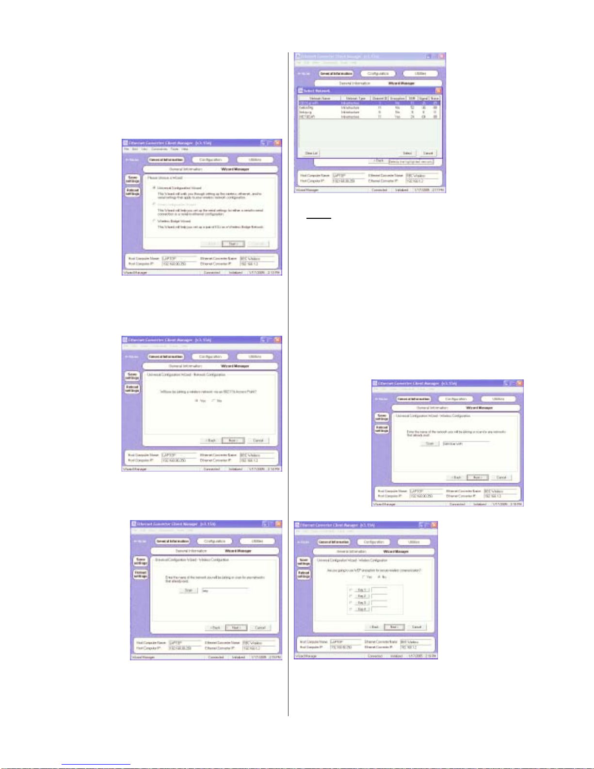
The first screen to appear is the Select EC screen
shown in Fig. CM-1. This screen lists information
about any devices associated in your network. If there
are no devices listed in the table, then you are not
connected. Recheck all connections and if you
connect to a router, switch or hub, make sure you
have followed the installation directions in #5 above.
TIONTION
TION
TIONTION
Fig. CM-1
Once you see the EC listed in the table, click on
the device to configure. Press the Select button and
you will be taken to the General Information window for
the EC (Fig. CM-2).
The Client Manager (CM) software can be installed
on a PC or workstation running Windows 98/ME,
2000, NT , or XP. This software is a GUI (Graphical
User Interface) which makes it easy to use. The
program allows you to locally or remotely perform the
following procedures:
√ Display a list of the EC units running on
the local network
√ Display and edit the current configuration
of the EC
√ Save and load configurations
√ Scan LAN’s in the area of the vessel
√ Update the EC firmware
Windows Installation – To install the Client
Fig. CM-2
Page 4
Quick Start Configuration
A quick way to configure the EC is through the
Wizard Manager. By clicking on this button, the
screen shown in the Fig. CM-3 appears. Click on the
Start button and let the Wizard guide you through the
configuration process.
Fig. CM-3
The next screen to appear (Fig. CM-4) allows you
to verify that you are joining a wireless network via an
802.1 1b access point. Be sure Yes is on and click
Next.
Fig. CM-6
Note: While several networks may appear to be
not encrypted and available, many are private
networks that may or may not be connected to
the Internet or have Internet availability. Public
Access Networks usually have an identifiable
name. Avoid networks with router names like
Linksys, Belkin and Netgear.
At the next screen (Fig. CM-7), you will see the
network you selected in the window. Click Next to
advance to the next screen (Fig. CM-8) where you will
be able to enter the Key if the network is encrypted.
For Public Access Networks you will want to be sure
the No button is highlighted and click Next.
Fig. CM-4
When the screen as seen in Fig. CM-5 appears,
you will have an opportunity to scan for available
wireless networks. Click on Scan.
Fig. CM-5
Fig. CM-6 shows the wireless networks within range
of your EC and their current status and whether
encryption is On or Off. Click to highlight network that
you wish to join then click Next.
Fig. CM-7
Fig. CM-8
The screen seen in Fig. CM-9 allows you to give
your EC its own identifier. It is not necessary to name
your EC; however, many people prefer to use the name
of their boat.
Page 5
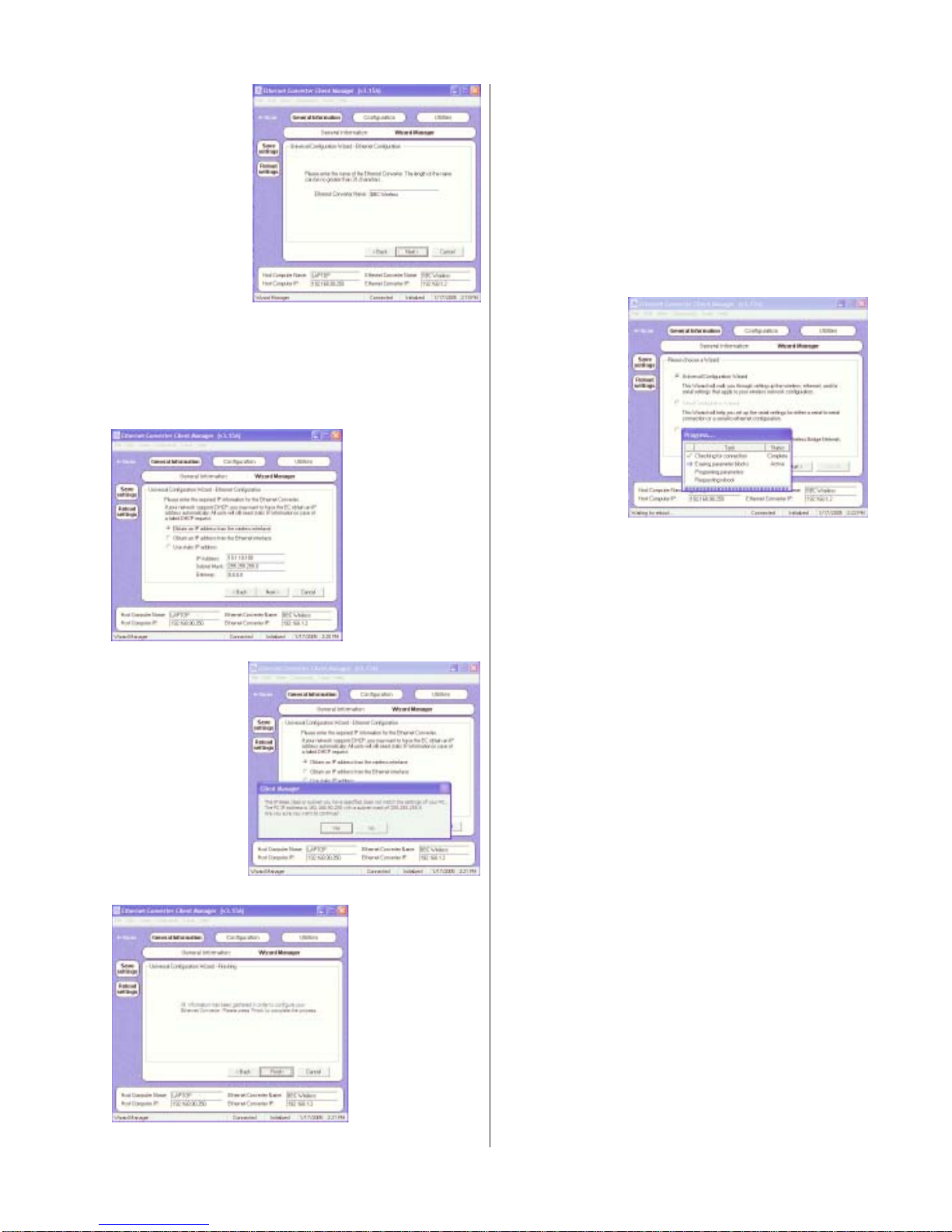
Fig. CM-9
At the next screen (Fig. CM-10), be sure to
highlight the button opposite “Obtain an IP address
from the wireless interface,” then click Next. When the
message window opens (Fig. CM-1 1), click Yes to
continue.
When the next screen appears (Fig. CM-12), it will
confirm the configuration information is in place and
ready to be executed. Click on Finish.
Part of the configuration process involves rebooting
the EC. The progress of the configuration can be
monitored as shown in Fig. CM-13. Af ter the reboot
process ends successfully , the Client Manager will
issue a reset command to the EC that will cause the
new configuration to be loaded and return to the Select
EC screen (Fig. CM-1). Again, highlight your EC and
click Select.
Fig. CM-13
Fig. CM-1 1
Fig. CM-10
Fig. CM-12
Y our EC is now configured and you are ready to join
the wireless network. Y ou can now close the Client
Manager and proceed to the Internet.
Client Manager Detail and Manual
Configuration
Begin at the Windows Start menu and choose
Programs. Y ou should see a folder called YDI. Select
this folder and click on Client Manager.
The first screen to appear is the Select EC screen
shown in Fig. CM-1.
This screen lists information about any devices
associated in your network. If there are no devices
listed in the table, then you are not connected.
Recheck all connections and if you connect to a
router, switch or hub, make sure you have followed the
directions in #5 above.
Once you see the EC listed in the table, click on
the device to configure. Press the Select button and
you will be taken to the General Information window for
the EC.
The window will automatically update as an EC is
discovered. If an EC has been disconnected, the
status of the EC will change to “Offline.” If any user is
logged in to an EC with the Client Manager, the st atus
will change to “Busy” and no other user will be given
access to that EC. Once the logged in user logs out,
the status will then reflect whether it is online or offline.
If you click the Advanced button, the screen shown in
the Fig. CM-14 appears and the Advanced button
toggles to Simple.
Page 6
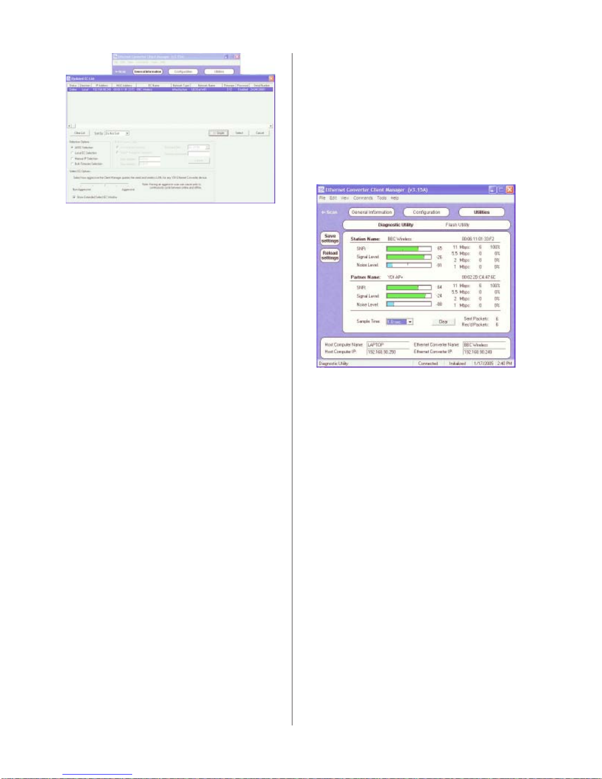
Fig. CM-14
The General Information screen displays informa-
tion about the connection with the device you selected
and is shown in the Fig. CM-2 There are two other
buttons at the top of this window. Configuration and
Utilities, and three buttons on the left – Scan, Save
Settings, and Reload Settings. The Scan button takes
you back to the Select EC screen. The Save Settings
button will load all changed parameters into the
associated EC. The Reload Settings button will restore
the parameters that are currently saved in the associated EC. Lastly , at the top of the screen, several dropdown menu items are available. They are: File, Edit,
View , Commands, T ools and Help.
For Manual Configuration, click the Configuration
button. This features three options:
Ethernet Configuration – This screen allows you to
specify the parameters associated with the EC’s local
Ethernet connection. The Change IP Information
button opens up a dialog box used to configure the IP
information. Y ou need to choose an IP address,
subnet mask, and gateway even if you are using
DHCP for the case in which a DHCP server can not be
found.
Serial Configuration – Although there is an option for
Serial Configuration, the EC does not use a serial
interface. All screens for the Serial settings should be
ignored since they are not applicable. The Client
Manager grays this option out.
Wireless Configuration – This screen allows you to
specify the parameters associated with the wireless
connection. Y ou can add, edit, or delete profiles. A
profile is a combination of settings that you can define
and then use over and over. The default profile is
Default IS Profile.
Finally , the Utilities screen features two buttons
(Fig. CM-15):
Diagnostic Utility – To check the reliability of the
radio link.
Flash Utility – T o update the firmware program on
the EC.
When you press the Update Firmware button, you
start the firmware upgrading process. A Flash Up date
Progress Screen will appear showing the different
steps as they take place. Af ter the update process
ends successfully , the Client Manager will issue a
reset command to the EC that will cause the new
program image to be loaded into RAM, and return to
the Select EC Screen. The Firmware Image File
should reflect the latest version that has been just
updated.
Fig. CM-15
CAUTION: If you power–cycle or turn the unit off
after a faulty update, it will cause the EC to fail
and require the unit to be sent back to GEOSat
for repair. Always log back in via the Client
Manager and re-run the update process as many
times as needed until it is successful before
removing the power or power–cycling the unit.
For detailed information about the Client Manager ,
please refer to the documentation in you CD ROM. In
addition, an online help is available by pressing F1 or
clicking Help Contents from the General Information
screen.
Page 7
Technical Support
Y our primary source of assistance is the dealer
from which you purchased this product. GEOSat
Solutions support staff should only be contacted
directly if you are unable to get satisfactory assistance
from your dealer.
Before you contact GEOSat Technical Support,
please make sure that you have read and thoroughly
understood all instructions outlined on this manual.
GEOSat Solutions, Inc.
2 Oakwood Blvd., Suite 195
Hollywood, FL 33020-1962
T elephone: 954-922-9585
T elephone: 954-922-9585
E-mail: [email protected]
www.geosatsolutions.com
Professional Installation Recommended
The GEOSat Mobile Wi-Fi Solution must be
installed as a complete system and should be installed by experienced antenna installation professionals who are familiar with Radio Frequency (RF) issues
such as gains and losses.
Failure to follow NMEA installation practices will
void the product warranty and may expose the end
user to excessive RF hazard.
Regulations regarding maximum antenna gains,
power output and maximum permissible exposure vary
from country to country . It is the responsibility of the
end user to operate within the limits of these regulations and to ensure that the installers who install this
device are aware of these regulations.
All antennas are intended to be installed outdoors.
FCC NOTICE
This equipment complies with FCC radiation
exposure limits set forth for an uncontrolled environment when installed as directed. This equipment
should be installed and operated with fix-mounted
antennas that are installed such that these antennas
will have a minimum of 2 meters (6.5 feet) of separation distance between the antenna and all persons
during normal operation.
This device complies with part 15 of the FCC rules.
Operation is subject to the following two conditions:
(1 ) This device may not cause harmful
interference, and
(2 ) This device must accept any interference
received, including interference that may cause
undesired operation.
T erabeam Wireless, the manufacturer , and/or
GEOSat Solutions, the systems integrator, is not
responsible for any radio or TV interference caused by
unauthorized modifications to this equipment. Such
modifications to this equipment could void the user’s
authority to operate the equipment.
GEOSaGEOSa
GEOSa
GEOSaGEOSa
GEOSat Solutions, Inc. warrants that your GEOSat Mobile Wi-Fi Solution is free of defects in material
and workmanship for a period of 12 months from the date of purchase. GEOSat will, at its option, repair
or replace any parts supplied by GEOSat as part of the Mobile Wi-Fi Solution Kit found to be defective in
normal use. Components of the GEOSat Mobile Wi-Fi Kit must be returned to the place of purchase
prepaid both ways.
GEOSat is not responsible for the cost of removal, reinstallation, or shipping to the place of repair.
GEOSat does not extend or modify the warranty period as a result or repair or replacement. GEOSat
Solutions’ obligation under this warranty is strictly of the GEOSat Mobile Wi-Fi unit only which GEOSat
is the integrator.
This warranty does not apply to damage or conditions in materials that are subject to normal rate of
wear by exposure to the elements or result from improper installation, abuse, tampering or misuse.
Warranty is void if the GEOSat Mobile Wi-Fi is altered in any way from the original integration/configuration.
GEOSat is not responsible for damage to any other equipment or property, or any other consequential or incidental damages of any kind, whether based on contract, negligence, or strict liability. Maximum liability shall not exceed the purchase price of the unit.
GEOSat Solutions cannot guarantee wireless signal availability.
The warranty is null and void if any of the following occurs:
• The EC enclosure is not sealed
• The antenna connections are not properly waterproofed
• The device is installed improperly or with incorrect connectors
• The devise is operated outside the recommended DC power specifications
• The devise is damaged by extreme forces of nature, lightning, or ‘Acts of God’
t Mobile t Mobile
t Mobile
t Mobile t Mobile
Special Warranty NoticeSpecial Warranty Notice
Special Warranty Notice
Special Warranty NoticeSpecial Warranty Notice
WW
i-Fi Limited i-Fi Limited
W
i-Fi Limited
WW
i-Fi Limited i-Fi Limited
WW
W
WW
arar
ar
arar
rr
antyanty
r
anty
rr
antyanty
 Loading...