

Page 1

Instruction Manual
Controller Type PE 22
¥ ‡
¥ ‡
33
Page 2
The technical data are not
binding. They are not
warranted characteristics
and are subject to change.
Please consult our General
Conditions of Supply.
Important Information
≠ Electrostatic discharges caused by touching the
printed circuit boards can cause the destruction
of individual components. Please take
appropriate precautions antistatic workplaces,
metallic connections to a water pipe, etc.
≠ In order to obtain the required protection
against physical contacts in accordance to DIN/
EN 60355-@, the external cable installation has
to be duly isolated and protected against
physical contacts.
Warnings:
≠ Any work done on the actuator may only be
carried out by authorized and trained personnel.
≠ These products are according to the Machine
Guidelines 98/37/EG (ancient 89/392/EWG), not
regarded as machines; they are, however, built
into installations which are regarded as machines.
Note
We distinctly emphasize that operation is
prohibited until it has been confirmed that the
machine (plant) into which the products have
been built corresponds to the conditions of the
EC Machine Guidelines 98/37/EG (ancient
89/392/EWG).
34
¥ ‡
Page 3

Contents
Page
1. General features 36
2. Specifications 37
3. Installation and assembly of the PE 22 37
3.1 Installation in electric actuator
EA 20, EA 30 37
3.2 Installation in electric actuator
EA 41, EA 50 39
4. Connection diagram for use as a positioner 41
5. Connection diagram for use as a process controller 41
6. Wiring of the PEV 122 supply unit
in the EA 41, EA 50 42
7. Block diagram of the PE 22 43
8. Balancing/adjusting the PER 22 43
9. Adjustments 45
10. Order Numbers 47
¥ ‡
35
Page 4
Controller Type PE 22 for installation in electric actuators
EA 20/EA 30 and EA 4@/EA 50
1. General Features
Electrically powered valves are increasingly being
driven by external reference inputs.
With the PE 22 Controller, the EA 20, EA 30, EA 4@
and EA 50 electric actuators can be employed as
follows:
≠ as a continuously adjustable positioner from
0. . .90° or 0. . .180°; in the process the aperture
angle of the valve is measured continuously and
compared with the setpoint
≠ as a process controller in conjunction with an
external sensor and a reference input.
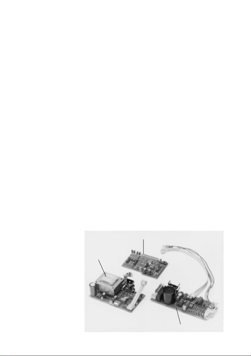
The PE 22 Controller comprises two parts (PEV 22/
PEV @22 and PER 22) and is preferably installed in
the actuator in the factory; it can, however, also
be supplied in kit form (Fig. @).
Fig. 1
36
PER 22 for EA 20, EA 30, EA 41 and EA 50
PEV 22 for
EA 20, EA 30
PEV 122 for EA 41, EA 50
¥ ‡
Page 5

2. Specifications
Connected voltage 1@5/230 V, 50–60 HZ
(switchable)
24 V 앑/=
Setpoint 0–5/10 V=/4–20 mA
Actual value, external
(process controller) 0–5/10 V=/4–20 mA
Actual value, internal
(potentiometer) 0–5/10 V=(90/180°)
Range when used
as positioner 0–90°/0–180°
Control PI, proportional range
characteristics continuously adjustable
when used as 8 to 210%, reset time
process controller continuously adjustable:
1,2 s to1,9 min
Duty cycle 100% at 25°C ambient
temperature for the EA 20/EA 30
50% at 25°C ambient
temperature for the EA 41/EA 50
Ambient temperature –10 to +50°C
conditions relative humidity 0 to 90%
3. Installation and assembly of the PE 22
Before installation and assembly starts,
the actuator must be moved to the <closed>
position.
3.1. Installation in electric actuator EA 20 and EA 30
3.1.1 Adjustment to mains voltage
Jumpers JP1 (230 V) and JP2 (@@5 V) on the PEV 22
supply unit must be plugged in according to the mains
voltage available (Fig. 2). As delivered: 230 V. JP@ is
plugged in on the 24 V version.
¥ ‡
37
Page 6

JP1
JP2
Bild 2
38
23 1
3.1.2 Mounting and connecting the PEV 22
supply unit
≠ separate actuator from mains
≠ detach electrical connections
≠ remove existing supply unit
≠ install PEV 22 supply unit and bolt on securely
≠ attach connecting cable (green = 1)
(black = N)
≠ connect earth to transformer (1)
3.1.3 Installing the PER 22 control unit
≠ bolt on PER 22 securely as illustrated (2+3)
≠ plug in the ribbon cable connection
¥ ‡
Page 7

3.2 Installation in electric actuator EA 4@/EA 50
3.2.1 Adjustment to mains voltage
≠ wire up as shown in Fig. 8
≠ Connector terminal: 1 = 115 V / 2 = 230 V / N = Neutral
Connector terminal
3.2.2 Mounting and connecting the PEV @22
supply unit
≠ separate actuator from mains
≠ detach electrical connections
≠ remove existing supply unit
≠ fit the PEV @22 in the same way (see Fig. 3)
≠ wire up as shown in Fig. 8
Fitting the PEV @22
printed circuit board
¥ ‡
Fig. 3
39
Page 8

Fig. 4
3.2.3 Installing the PER 22 control unit
≠ slide the printed circuit board into the groove
provided, as shown in Fig. 5
≠ secure it with the bracket and bolts provided
(Fig. 4 + 5)
≠ plug in the ribbon cable connection
Fastening bolts
Fig. 5
40
¥ ‡
Page 9

4. Connection diagram when used
as a positioner with internal actual value sensor
(potentiometer @99 @90 @40)
Fig. 6
M
1 S2 1 S1
closed
242
red
PS2 S2 PS1 S1
PEV 22
PEV @22*
M1
M2
1N
Ph
+
@234
L@ N PE
connection
mains
EA 20, EA 30
+ @0 V/
0 V 0 V
5 mA
black
red
2
3
@99 @90 @40
actual value
internal potentiometer
EA 41, EA 50
white
1
open
4
green
PER 22
JP4
N
@@0–@20 V 앑,
–
200–240 V앑, 24 V 앑/ =
JP9
34 56 789 @0@@
connecting
cable
+–+–
0–5 V/@0 V =
4–20 mA
inputs for external
setpoint
5. Connection diagram when used
as a process controller with 4–20 mA or 0–5/@0 V
external actual value sensor (e.g. transmitter)
Fig. 7
red
1 S2 1 S1
closed
242
open
EA 20, EA 30
4
green
EA 41, EA 50
PS2 S2 PS1 S1
PEV 22
PEV @22*
M
M1
M2
1N
PH
+
@234
L@ N PE
mains
connection
* see Fig. 8
¥ ‡
JP4
N
@@0–@20 V 앑,
–
200–240 V앑, 24 V 앑/ =
JP9
34 56 789 @0@@
connecting
cable
0–5 V/@0 V =
+
––
inputs for external
setpoint
PER 22
+ @0 V/
0 V 0 V
5 mA
+
4–20 mA
+
+– –
0–5 V/@0 V =
4–20 mA
inputs for external
actual value
41
Page 10

6. Wiring of the PEV @22 supply unit in
the EA 4@/ EA 50
Fig. 8.1
Fig. 8.2
EA 41
115/230 V
EA 41
24 V⫽/앑
Transformer
T1
brown
grey
black
1N21011121314
115 V
230 V
32
14
L1+N-PE
M
open
S2
S1
green
S1S2
PS1
JP4
white
white
closed
1
2
3
4
5
6
red
PS2
PEV 122
M1
M
M2
open
S2
closed
red
1
2
3
PS2
S2
4
5
6
PS1
PEV @22
Connection
cable
S1
green
S1
JP4
M1
M2
1
N
42
connection
cable
L1+N–PE
mains connection
¥ ‡
Page 11

7. Block diagram ot the PE 22
1
3
4
5
6
7
8
9
10
11
1
3
I
U
+ @5 V
PER 22
1
1
3
I
U
5
4
24
6/1
1
7
6/2
8
max.
min.
2910
U
f
910
U
f
PEV 22
PEV 122
+ 24 V
+ 15 V
– 15 V
=
앑
11
12
11
13
M1
M2
S1
PS1
S2
PS2
1
2
8. Balancing/adjusting the PER 22
8.1 Adjusting the input signals
Various operating conditions can be adjusted
on control unit PER 22 by means ot the jumpers
(JP@–JP8) provided.
JP1
JP2
JP3
JP4
JP5
JP6
JP7
JP8
3 4567 8 91011
P3
P2
P1
JP9
1 Amplifier
2 Inverting amplifier
3 Current-voltage converter
4 Filter
5 Setpoint smoothing
6 Adder
7 Integrator
8 Limiter
9 Voltage-frequency
converter
10 Monostable multivibrator
11 Logic
12 Motor driver H bridge
13 Power supply unit
¥ ‡
43
Page 12

8.1.1 Used as a positioner with integrated
potentiometer
Jumper plugged in
Actual value
Rotation 90° JP5, JP7
Rotation 180° JP5, JP8
Setpoint 0– 5 V JP1, JP3
0–10 V JP1, JP4
4–20 mA JP2, JP3
8.1.2 Used as a process controller with
external sensor
Jumper plugged in
Actual value 0– 5 V JP5, JP7
Setpoint 0– 5 V JP1, JP3
0–10 V JP5, JP8
4–20 mA JP6, JP7
0–10 V JP1, JP4
4–20 mA JP2, JP3
8.2 Installing the internal potentiometer for
actual value feedback
Important: Ensure that during installation (with
valve closed) the potentiometer is at the left-hand
stop when viewed from above (turn counter-clockwise), i.e. the resistance between the red and
white wires must be 0 Ohm.
(See EA 20/EA 30/EA 41/EA 50 Instruction
Manual).
44
¥ ‡
Page 13

9. Adjustments
9.@ Used as positioner with internal potentiometer
Potentiometers P@ and P2 (Fig. @0) must be turned
clockwise as far as the stop (max. 28 revs.).
This is already set in the factory.
The regulating speed of the valve can be adjusted
between 7 and @5 s by means of potentiometer P3.
Time
shorter
왗
Turn
counterclockwise
(CCW)
Potentiometer
P3
P3 P1 P2
9.2 Used as a process controller
Adjusting the parameters.
The parameters are set as follows in the factory:
Proportional range maximum (2@0%)
Reset time maximum (1.9 min)
Turn
clockwise
(CW)
Fig. 10
왘
Time
longer
¥ ‡
45
Page 14

The controller thus displays a predominantly proportional action.
Three potentiometers are provided on the control
unit (PER 22) for special adjustments:
P@ for adjusting reset time
P2 for adjusting the proportional range
P3 for delaying the setpoint (remains at left-hand
stop)
If the setscrew is turned counter-clockwise:
≠ the reset time is shortened (I component is
increased)
≠ the proportional range is diminished (P compon-
ent is reduced)
Control parameters
␣
P max.
l min.
Start Flow
Set 50%
Osc?
No
Set 20%
Osc?
No
20%
Yes
액
Yes
Yes
No
Red P
Reduce P
component
Red P
Inc. I
Increase I
component
Start of adjustment
Basic setting:
maximum P component (P2)
Basic setting:
maximum I component (P1)
Setpoint: 50%
Start flow
Control circuit
oscillating?
Setpoint: 20%
Start flow
Control circuit
oscillating?
Acutal value = 20%?
End of adjustment
46
¥ ‡
Page 15

10. Order Numbers
Article Code
EA 20 actuator with integrated PE 22 as positioner
(including @99 @90 @40)
@@5/230 V, 50–60 Hz @98 @50 434
24 V=/앑 @98 @50 435
EA 20 actuator with integrated PE 22 as processor controller
(without @99 @90 @40)
@@5/230 V, 50–60 Hz @98 @50 436
24 V=/앑 @98 @50 437
EA 30 actuator with integrated PE 22 as positioner
(including @99 @90 @40)
@@5/230 V, 50–60 Hz @98 @50 7@2
24 V=/앑 @98 @50 7@3
EA 30 actuator with integrated PE 22 as processor controller
(without @99 @90 @40)
@@5/230 V, 50–60 Hz @98 @50 7@4
24 V=/앑 @98 @50 7@5
EA 41 actuator with integrated PE 22 as positioner
(including @99 @90 @40)
@@5/230 V, 50–60 Hz @98 @50 70@
24 V=/앑 @98 @50 702
EA 41 actuator with integrated PE 22 as process controller
(without @99 @90 @40)
@@5/230 V, 50–60 Hz @98 @50 703
24 V=/앑 @98 @50 704
EA 50 actuator with integrated PE 22 as positioner
@@5/230 V, 50–60 Hz @98 @50 706
24 V=/앑 @98 @50 707
EA 50 actuator with integrated PE 22 as process controller
@@5/230 V, 50–60 Hz @98 @50 708
24 V=/앑 @98 @50 709
PE 22 in kit form
PER 22 controller PCB @99 @90 225
PEV 22 supply unit: @@5/230 V, 50–60 Hz @99 @90 236
24 V=/앑 @99 @90 237
PEV @22 supply unit: @@5/230 V, 50–60 Hz @99 @90 229
24 V=/앑 @99 @90 230
Potentiometer @99 @90 140
¥ ‡
47
Page 16

¥ ‡
A Georg Fischer Rohrleitungssysteme GmbH, Sandgasse 16, 3130 Herzogenburg
Tel. +43(0)2782/8 56 43-0, Fax +43(0)2782/8 51 56, e-mail: office@georgfischer.at
AUS George Fischer Pty. Ltd., 4 Jacks Road, South Oakleigh, Victoria 3¢67, Tel. +61(0)3/95 63 88 99, Fax +61(0)3/95 63 89 66
e-mail: sales@georgefischer.com.au
B/L Georg Fischer NV/SA, Digue du Canal 109-¢¢¢ — Vaartdijk 109-¢¢¢, 1070 Bruxelles/Brüssel
Tél. +32(0)2/556 40 20, Fax +32(0)2/524 34 26, e-mail: info.be@be.piping.georgfischer.com
BR George Fischer Ltda, Av. das Nações Unidas 21689, CEP 04795-100 São Paulo, SP, Brasil
Tel. +55(0)11/247 13 11, Fax +55(0)11/247 60 09
CH Georg Fischer Rohrleitungssysteme (Schweiz) AG, Amsler-Laffon-Strasse ¢, Postfach, 8201 Schaffhausen
Tel. +41(0)52 631 30 26, Fax +41(0)52 631 28 97, e-mail: info@rohrleitungssysteme.georgfischer.ch
CHINA Georg Fischer Piping Systems Ltd. Shanghai, No. 2Ý8 Kang Qiao Dong Rd., Shanghai 201319
Tel. +86(0)2¢/58 13 33 33, Fax +86(0)2¢/58 13 33 66, e-mail: gfsro@public.shanghai.cngb.com
Georg Fischer Piping Systems (Trading) Ltd. Shanghai, No 516 Fute Bei Road, Waigaoqiao Free Trade Zone, 200131 Pudong,
Shanghai, Tel. +86(0)21/5868 0278, Fax +86(0)21/5868 0264, e-mail: gftrade@sh.cngb.com
D Georg Fischer GmbH, Daimlerstraße 6, 73095 Albershausen, Tel. +49(0)7161/302-0, Fax +49(0)7161/3 0 2 25 9
e-mail: info@georgfischer.de, Internet: http://www.rls.georgfischer.de
Georg Fischer DEKA GmbH, Postfach 1145, 35228 Dautphetal, Tel. +49(0)6468/91 51-0, Fax +49(0)6468/91 52 21/22
e-mail: info@dekapipe.de
DK/IS Georg Fischer A/S, Klintehøj Vænge 17, 3460 Birkerød, Tel. +45 45 81 19 75, Fax +45 45 81 16 22
E Georg Fischer S.A., Sistemas de tuberías para la industria, Alcalá, 85, 2
Tel. +34(0)9¢/781 98 90, Fax +34(0)9¢/426 08 23, e-mail: info@georgfischer.es
F George Fischer S.A., 105–1¢3, rue Charles Michels, 93208 Saint-Denis Cedex 1
Tél. +33(0)1/49 22 ¢3 4¢, Fax +33(0)¢/49 22 ¢3 00, e-mail: info@georgefischer.fr
GB George Fischer Sales Limited, Paradise Way, Coventry, CV2 2ST, Tel. +44(0)2476/535 535, Fax +44(0)2476/530 450
e-mail: info@georgefischer.co.uk, Internet: http://www.georgefischer.co.uk
GR Georg Fischer S.p.A., Athens Branch, 101, 3rd September Str., 10434 Athen
Tel. +30(0)1/882 0491, Fax +30(0)1/881 0291, e-mail: dderv_piping_gf@oneway.gr
I Georg Fischer S.p.A., Via Sondrio 1, 20063 Cernusco S/N (MI)
Tel. +3902/92 18 61, Fax +3902/92 14 07 85, e-mail: office@piping.georgfischer.it
ID George Fischer Representative Office, c/o Wisma Aria, 3rd Floor, Jl. H.O.S. Cokroaminoto 81, Jakarta 10310, Indonesia,
Tel. +62(0)21/391 48 62, Fax +62(0)21/391 48 63
IND George Fischer Piping Systems Ltd, India Branch Office, Solitaire Corporate Park, 532, Building No. 5, 3rd Floor, Chakala,
Ghatkopar Link Road, Andheri (E), 400 093 Mumbai, Tel. +91(0)22/820 2362, Fax +91 22-820 2462, e-mail: wpfunder@vsnl.net
J Georg Fischer Ltd, 2-47, Shikitsuhigashi 1-chome, Naniwa-ku, 556-8601 Osaka
Tel. +81(0)6/664 82 59 4, Fax +81 6-664 82 56 5, e-mail: kgf-yosi@kubota.co.jp
N Georg Fischer AS, Rudsletta 97, ¢35¢ Rud, Tel. +47(0)67¢ 7¢7 40, Fax +47(0)67¢ 392 92
NL Georg Fischer N.V., Lange Veenteweg 19, Postbus 35, 8160 AA Epe, Tel. +31(0)578/678222, Fax +31(0)578/621768
e-mail: info.vgnl@nl.piping.georgfischer.com, Internet: http://www.georgfischer.nl
PL Georg Fischer Sp. z o.o., ul. Radiowa 1A, 01-485 Warszawa, Tel. +48(0)22/638 91 39, Fax +48(0)22/638 00 94
RO Georg Fischer Rohrleitungssysteme AG, Rep. Office Romania, 11 Barbu Delavrancea, 70000 Bucharest - Sector 1
Tel. +40(0)1/222 91 36, Fax +40(0)1/222 91 77, e-mail: office@georgfischer.ro
RU Georg Fischer Piping Systems Ltd, Moscow Representative Office, Sheremetievskaya ul., 47, 127521 Moscow,
Tel. +7 095/219 9604, Fax +7 095/232 3625, e-mail: lazer@orc.ru
S/FIN Georg Fischer AB, Box113, 12523 Älvsjö-Stockholm, Tel. +46(0)8/506 77 500, Fax +46(0)8/749 23 70
e-mail: info@georgfischer.se, Internet: http://www.georgfischer.se
SGP George Fischer Pte. Ltd., ¢5 Kaki Bukit Road 2, KB Warehouse Complex, 4¢7 845 Singapore/Singapore
Tel. +65(0)7/47 06 ¢¢, Fax +65(0)7/47 05 77, e-mail: info@georgfischer.com.sg
USA George Fischer Inc., 2882 Dow Avenue, Tustin, CA 92780-7285, Tel. +1(0)714/731 88 00, Toll Free 800/854 40 90
Fax +1(0)714/7 3¢ 46 88, e-mail: info@us.piping.georgefischer.com, Internet: http://www.us.piping.georgefischer.com
Export Georg Fischer Rohrleitungssysteme AG, Ebnatstrasse ¢¢¢, Postfach, CH-820¢ Schaffhausen, Tel. +41(0)52 63¢ ¢¢ ¢¢
Fax +41(0)52 63¢ 28 93/631 28 58, e-mail: export@piping.georgfischer.com, Internet: http://www.piping.georgfischer.com
@98.@50.442
Fi @99@/ @,2,4d (3.00) @000 © Georg Fischer Rohrleitungssysteme AG, CH-820@ Schaffhausen/Schweiz, @996 Printed in Switzerland
a
, 28009 Madrid
 Loading...