

Page 1
Instruction Manual
Electrical Actuator Unit
Type EA 30 for Type 035 and @08
GEORGE FISCHER ˙GF˙
GEORGE FISCHER …
41
Page 2

The technical data are not
binding. They are not
warranted characteristics and
are subject to change. Please
consult our General Conditions
of Supply.
42
GEORGE FISCHER …
Page 3

Table of Contents Page
1. Introduction 44
2. Design of the actuator 45
2.1 Mains voltage selection 46
2.2 Wiring diagram of the standard version 47
3. Design of the actuated valve 48
3.1 Butterfly valve type 035 48
3.2 Ball valve type 108 48
4. Installation of the actuator 49/50
5. Specifications 51
5.1 Actuator unit 51
5.2 Block diagram 52
5.3 Dimensions 52
6. Assembly and wiring of the modular components 53
6.1 Mechanical limit switch 54
6.2 Inductive limit switch 55
6.3 Potentiometer 56
6.4 Operating time adjustment module (Vario) 57
6.5 Heating element 58
7. Troubleshooting guide 59
8. Spare parts list 60
GEORGE FISCHER …
43
Page 4

1. Introduction
This instruction manual contains all the information regarding design, installation and start-up
procedure for the electrical actuator unit type
EA 30.
Warnings:
쐌 Do not work on this unit before disconnecting it
from the mains!
쐌 The actuator is factory preset to a mains
voltage of 230 V AC. By all means refer to
Item 2.1.
쐌 Electric actuators do not have a safety position.
In case of a mains breakdown, the actuator
resp. the valve remains in its actual position.
≠ Any work done on the actuator may only be
carried out by authorized and trained
personnel.
≠ These products are according to the Machine
Guidelines 98/37/EG (ancient 89/392/EWG),
not regarded as machines; they are, however,
built into installations which are regarded as
machines.
44
Note
We distinctly emphasize that operation is
prohibited until it has been confirmed that the
machine (plant) into which the products have
been built corresponds to the conditions of the
EC Machine Guidelines 98/37/EG (ancient
89/392/EWG).
GEORGE FISCHER …
Page 5
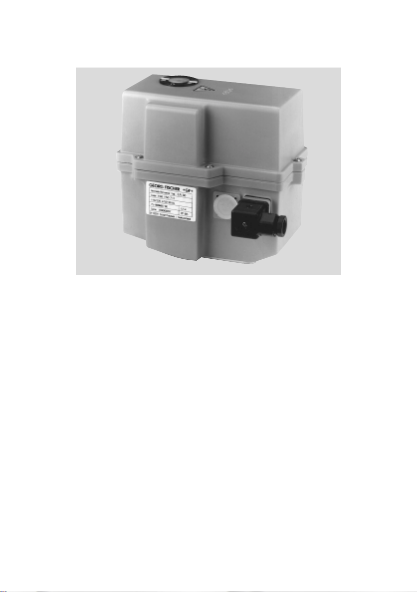
2. Design of the actuator
The standard version of the electrical actuator
EA 30 consists of the following elements: spurwheel gear, DC motor, power supply board as
well as components for limit positioning. For
special applications, the actuator can be
equipped with additional modular components
(see Item 6).
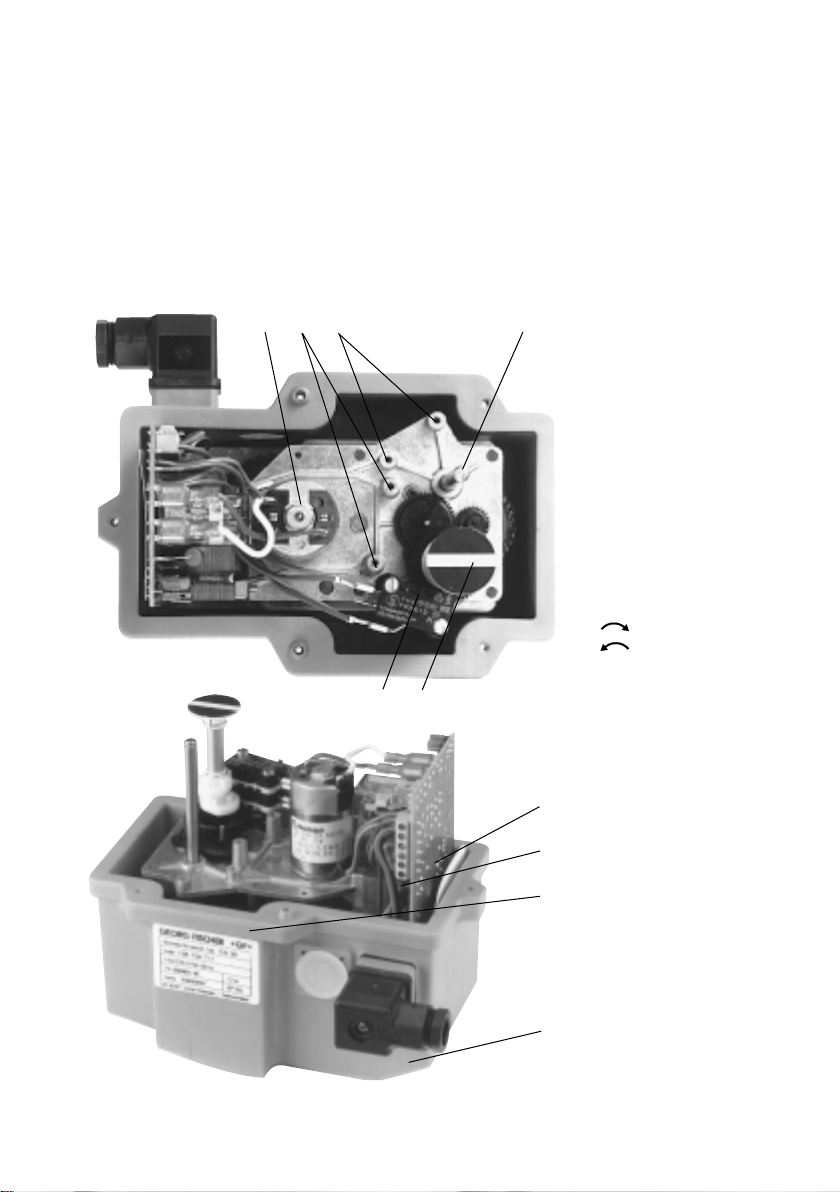
543 2
1 Limit Switch S1 and S2
2 Spindle for additional
switching cams
3 Mounting space for addi-
tional limit switches
4 Mounting space for
potentiometer and/or
operating time adjustment
module
5 DC motor
6 Visual position indicator
valve closes
valve opens
GEORGE FISCHER …
16
4
1 Spur-wheel gear
3
2 Unit plug
3 Connector terminal strip
1
2
for external connections
(max. 1.5 mm
4 Electrical supply unit
2
)
45
Page 6
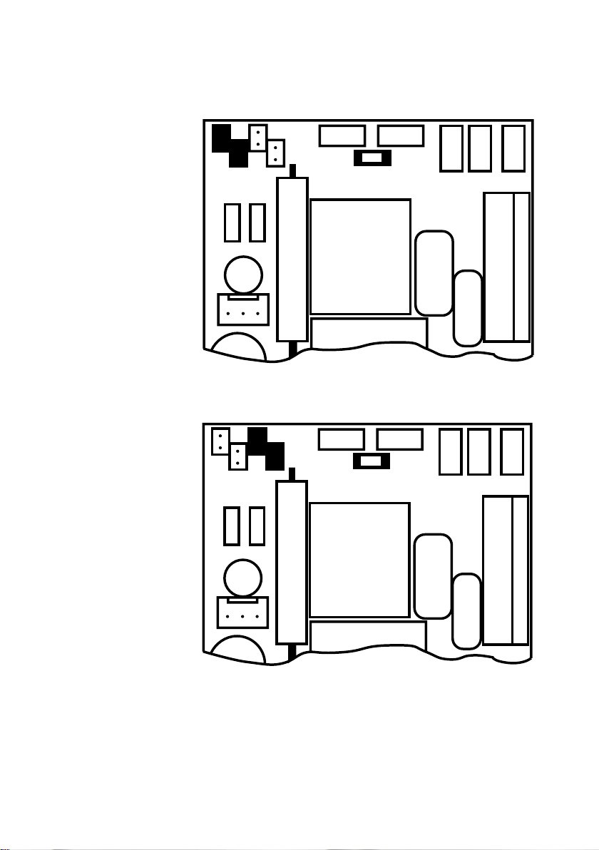
230 V, 50–60 Hz
2.1 Mains Voltage Selection
The actuator is factory
preset for 230 V앑
1@5 V, 50–60 Hz
Selecting 1@5 V앑 can be
done by changing the
corresponding jumpers as
shown in the diagram
왗왘
왗왘
46
Do not work unit when under voltage!
GEORGE FISCHER …
Page 7
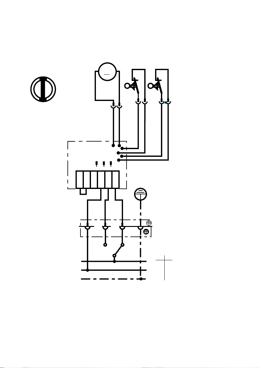
2.2 Wiring Diagram
Standard Version
Position indicator
open
S1
1
green
M1
12
green
1
456
black
3
M
white
M2
S1
S2
E
F
D
N
red
2
A
C
B
brown
close
S2
1
2
green
red
green/yellow
2
red
<closed>
<open>
B A
Do not use S@ and S2 for electric position
feedback.
GEORGE FISCHER …
DC AC
ѿ L1
Ҁ N
PE
47
Page 8

3. Design of Actuated Valve
The electrical actuator type EA 30 can be
mounted on a valve via a suitable intermediate
housing. The actuators are delivered ex factory
in the <open> position. Pictured below under 3.1
and 3.2 are the assembly parts necessary for
the automatic butterfly valve type 035 as well as
the automatic ball valve type 108 from George
Fischer. Both end positions (open and closed)
are pre-set in the factory. It is necessary to readjust them after the customer has assembled the
unit (see Item 4).
3.1 Butterfly valve 035 3.2 Ball valve 108
George Fischer George Fischer
Actuator EA 30
48
Intermediate housing
with coupling device
Hand lever
for emergency
override
Butterfly valve 367
George Fischer
Ball valve 370
George Fischer
GEORGE FISCHER …
Page 9

4. Installation of the actuator
Warning:
Before the actuator is connected to the mains,
the following must be checked:
≠ is the actuator adjusted to the correct mains
voltage?
(see Item 2.1)
≠ are the electrical connections correct?
(see Item 2.2)
Adjustments
If a complete actuated valve is being supplied
by George Fischer, no further adjustments are
necessary. If the customer assembles the unit or
afer a repair, the end positions must be checked
and if necessary adjusted. Adjustments can only
be done on dismounted valves.
Limit switch positions
Switch S1 opens at <open> position
Switch S2 opens at <closed> position
(see diagram in the margin)
S2
S1
Procedure
Both switching cams S1 and S2 are to be
adjusted so that the actuating angle is less than
90°쏝). Drive the actuator until one limit switch,
either <closed> or <open> is operated.
The end positions can be adjusted by moving the
switching cams, as the actuator follows them.
쐌 For George Fischer ball valves an exact
90°쏝) rotation should be set.
쐌 For George Fischer butterfly valves the
<closed> position should be adjusted according to the following directions.
GEORGE FISCHER …
49
Page 10

G/2
a
open
b
a–b
DN d a–b
mm mm mm
65 75 4
80 90 4
Setting the <closed> position in actuators
At the <closed> position in butterfly valves the
disk is not exactly vertical to the pipe axis. Deviation values can be taken from the following
table.
50
GEORGE FISCHER …
Page 11

5. Specifications
5.1Actuator unit
Nominal voltage @@5/ 230 V, 50–60 Hz
Power consumption @2 W
Protection IP 65 in accordance with DIN 40050
Duty cycle @00% at 25 °C / 70% at 50 °C, 20 min
Overload protection Dependent on current and time
Electric connection Cable plug 3 P+E in accordance with
Control time 12 s / 90° 쏝)
Angle of operation max. 270°, set to 90°
Continuous torque 25 Nm
Peak torque 50 Nm
Operating temperature –@0° to +50 °C
Permissible humidity 0–98%, non-condensing
Body material PP fiberglass reinforced
Position indicator visual, integrated
1)
The overload protection is designed to protect
(switchable)
24 V = / 24 V, 50–60 Hz
48 V, 50–60 Hz on request
(automatic reset)
DIN 43650
additional cable connections PG @@
external screws rust-proof
1)
2)
both motor and power supply board. If the overload protection device has triggered, it will reset
automatically when the unit has cooled down
sufficiently and the actuator will operate again.
2)
For temperatures below –@0 °C the heating element Nr. @98 @90 @42/ . . @43 should be installed
(see Item 6.5).
GEORGE FISCHER …
51
Page 12

5.2 Block Diagram
Open
L
Closed
1
2
input voltage
S1
S2
selection
230 V
1@5 V
power supply
overload
protection
M
N
N
5.3 Dimensions
230 V
1@5 V
reversing circuit
72
159
56.4
52
63.7
185
120.7
61
146
85
GEORGE FISCHER …
15
Page 13

6. Assembly and Connection
of Modular Components
The electrical actuator EA 30 is equipped with
fastening points which allow for additional
modular components to be mounted.
The configuration of these points is described
under Section 2. The electrical connection is made
by means of a second cable plug or a threaded
cable joint (depending on the number of
connecting wires). The respective kits are prepared
for installation, the electric cables are cut to size
and package accordingly.
In the following sections, the corresponding
assembly points and the wiring are illustrated.
GEORGE FISCHER …
53
Page 14

6.1 Mechanical limit switches
Description Technical Data Code
Kit with 2 additional auxiliary switches 250 V 앑, @0 A @99 @90 @38
Kit with 4 additional auxiliary switches 250 V 앑, @0 A @99 @90 @39
Kit with 2 additional auxiliary switches 4–30 V = @99 @90 @49
with gold contacts 1–@00 mA
1
2
Wiring diagram
Nr. 199 190 139
S8
214
1
4
S6
S7
1
4
2
2
M
S5
2
1
4
F
E
654 N21
1 Additional switching cams
2 Limit switch S5, S6 or
S5 to S8
Wiring diagram
Nr. 199 190 138, /. ..149
S6
1
4
black
white
S5
2142
black
red
S2
S1
D
M
F
D
E
65 4 2 1
N
S1
S2
54
1
B
A
DC AC
ѿ L1
Ҁ N
PE
123
A
B
DC AC
ѿ L1
Ҁ N
PE
GEORGE FISCHER …
Page 15

6.2 Inductive limit switches
The mechanical installation of these switches is
identical to those under 6.1.
An additional metal part must be mounted so
that the active surface of the inductive switch
can be activated.
Description Technical Data Code
Kit with 2 additional auxiliary switches 9,6–55 V = @99 @90 @46
inductive, with LED NPN 0,2 A
Kit with 2 additional auxiliary switches 9,6–55 V = @99 @90 @47
inductive, with LED PNP 0,2 A
Kit with 2 additional auxiliary switches 5–24 V = @99 @90 @48
inductive Namur @0 mA
Wiring Diagram Wiring Diagram
Nr. @99 @90 @46 NPN Nr. @99 @90 @48
Nr. @99 @90 @47 PNP
S6 S5
–+A
rot
red
black
white
weiss
schwarz
3
+
–
GEORGE FISCHER …
M
BA
S1 S2
DC AC
+L1
–N
PE
black
white
schwarz
weiss
321
––
++
black
schwarz
–+A +– +–
green
white
weiss
grün
schwarz
black
21
S6
S6
+ NPN
+ NPN
– PNP
– PNP
654N21
S5
S5
F
ED
white
weiss
654N21
M
F
ED
BA
S1 S2
DC AC
+L1
–N
PE
55
Page 16

6.3 Potentiometer
The potentiometer must be mounted on closed
valves. Before mounting, the potentiometer must
be turned to the end position, so that 0–⏲ ist
measured between the red and the white connecting wires.
Description Technical Data Code
Potentiometer kit 1–k액 @99 @90 @40
Wiring Diagram
Nr. 199 190 140
56
white
CW
red
CCW
321
black
M
D
FE
654N21
B
S1
S2
A
DC AC
ѿ L1
Ҁ N
PE
GEORGE FISCHER …
Page 17

6.4 Operating time adjustment module
(Vario)
T =20–@60 seconds, Nr. 199 190 144
(The vario is driving the motor stepwise).
Description Technical Data Code
Operating time adjustment module 20–@60 s @99 @90 @44
1 Potentiometer for time
1
adjustment
time is reduced
왔
time is extended
왔
2
GEORGE FISCHER …
왗왘
2 The operating time adjust-
ment module is connected
electrically (2) on the
power supply to this plug
unit.
57
Page 18

6.5 Heating element
Description Technical Data Code
Heating element 100–120 V, 50–60 Hz @99 @90 @42
200–240 V, 50–60 Hz
Heating element 24 V = / 앑 @99 @90 @43
1 Heating cartridge
2 Temperature switch
Switching point on: 0 °C
Switching point off: + 5 °C
3 Mounting bracket
Wiring Diagram
Nr. 199 190 142
Nr. 199 190 143
1
rot
white
weiss
red
2
3
S1 S2
58
213
F
ED
654N21
B
A
DC AC
+L1
–N
PE
GEORGE FISCHER …
Page 19

7. Troubleshooting Guide
Problem Possible Error Solution
Motor does not run no mains voltage find customer's error
(terminal 1, 2, 3)
internal wiring error check actuator
switching cams S1 and S2 see Item 4
adjusted incorrectly
Motor only runs in throw-over relay does not replace power supply
one direction function board
Transformer gets wrong input voltage see Item 2.1
very hot selected
Overload protection friction torque of valve clean and lubricate
triggers (self resetting) too high valve
defective motor replace motor/
gear assembly
Valve does not close switching cams S1 and/or see Item 4
or open correctly S2 not adjusted
Please consult your nearest George Fischer
representative in the event of problems arising.
GEORGE FISCHER …
59
Page 20

8. Spare parts list
Description Code
1 Unit plug, complete @98 000 147
2 Gear box and motor (irrespective of voltage) @98 800 310
3 Power supply unit
1@5 /230 V 앑/ 50–60 Hz @98 150 586
24 V = / 앑 @98 150 587
48 V 앑 @98 150 588
Electrical Actuator, complete
1@5 /230 V 앑/ 50–60 Hz @98 150 711
24 V = / 앑 @98 150 710
Cover set consisting of: @98 000 138
1 cover 1 clamp
1 showcase inspection glass 1 seal
1 O-Ring 5 PT-screws
Sealing set consisting of: @98 000 139
4 screw 1 sealing ring
5 PT screw 4 spring washer
1 shaft seal 1 O-Ring
Limit switch set consisting of: @98 000 140
2 limit switches
4 screws
4 washers
Position indicator @98 800 899
2
3
60
Butterfly Valve Type 035
dDN Intermediate housing Intermediate housing
mm mm inch override
75 65 21/2 198 000 120 198 000 126
90 80 3 198 000 121 198 000 127
with manual override without manual
Ball Valve Type 108
dDN Intermediate housing
with manual override
mm mm inch
75 65 21/2 198 000 132
90 80 3 198 000 133
Warning:
Beware of
turning bolt in the
intermediate
housing with
manual override
GEORGE FISCHER …
1
Page 21

GEORG FISCHER …
A Georg Fischer Rohrleitungssysteme GmbH, Sandgasse 16, 3130 Herzogenburg
Tel. +43(0)2782/8 56 43-0, Fax +43(0)2782/8 51 56, e-mail: office@georgfischer.at
AUS George Fischer Pty. Ltd., 4 Jacks Road, South Oakleigh, Victoria 3¢67
Tel. +61(0)3/95 63 88 99, Fax +61(0)3/95 63 89 66, e-mail: sales@georgefischer.com.au
B/L Georg Fischer NV/SA, Digue du Canal 109-¢¢¢ — Vaartdijk 109-¢¢¢, 1070 Bruxelles/Brüssel
Tél. +32(0)2/556 40 20, Fax +32(0)2/524 34 26, e-mail: info.be@be.piping.georgfischer.com
CH Georg Fischer Rohrleitungssysteme (Schweiz) AG, Amsler-Laffon-Strasse ¢, Postfach, 8201 Schaffhausen
Tel. +41(0)52/631 30 26, Fax +41(0)52/631 28 97, e-mail: info@rohrleitungssysteme.georgfischer.ch
CHINA Georg Fischer Piping Systems Ltd. Shanghai, No. 2Ý8 Kang Qiao Dong Rd., Shanghai 201319
Tel. +86(0)2¢/58 13 33 33, Fax +86(0)2¢/58 13 33 66, e-mail: gfsro@public.shanghai.cngb.com
D Georg Fischer GmbH, Daimlerstraße 6, Postfach 1154, 73093 Albershausen
Tel. +49(0)7161/302-0, Fax +49(0)7161/30 2 2 59 , e-m ail: info@georgfischer.de, Internet: http://www.rls.georgfischer.de
Georg Fischer DEKA GmbH, Postfach 1145, 35228 Dautphetal, Tel. +49(0)6468/91 51-0, Fax +49(0)6468/91 52 21/22
e-mail: info@dekapipe.de
DK/IS Georg Fischer A/S, Klintehøj Vænge 17, 3460 Birkerød, Tel. +45 45 81 19 75, Fax +45 45 81 16 22
E Georg Fischer S.A., Sistemas de tuberías para la industria, Alcalá, 85, 2
Tel. +34(0)9¢/781 98 90, Fax +34(0)9¢/426 08 23, e-mail: info@georgfischer.es
F George Fischer S.A., 105–1¢3, rue Charles Michels, 93208 Saint-Denis Cedex 1
Tél. +33(0)1/49 22 ¢3 4¢, Fax +33(0)¢/49 22 ¢3 00, e-mail: info@georgefischer.fr
GB George Fischer Sales Limited, Paradise Way, Coventry, CV2 2ST, Tel. +44(0)2476/535 535, Fax +44(0)2476/530 450
e-mail: info@georgefischer.co.uk, Internet: http://www.georgefischer.co.uk
I Georg Fischer S.p.A., Via Sondrio 1, 20063 Cernusco S/N (MI), Tel. +3902/92 18 61, Fax +3902/92 14 07 85
e-mail: office@piping.georgfischer.it
J Kubota George Fischer Ltd., 2-47, Shikitsuhigashi, 1-chome, Naniwa-ku, Osaka 556-8601
Tel. +81(0)6/6648 25 62, Fax +81(0)6/66 48 25 65, e-mail: kgf-yosi@kubota.co.jp
N Georg Fischer AS, Rudsletta 97, ¢35¢ Rud, Tel. +47(0)67/¢7 ¢7 40, Fax +47(0)67/¢3 92 92
NL Georg Fischer N.V., Lange Veenteweg 19, Postbus 35, 8160 AA Epe
Tel. +31(0)578/678222, Fax +31(0)578/621768, e-mail: info.vgnl@nl.piping.georgfischer.com
Internet: http://www.georgfischer.nl
PL Georg Fischer Sp. z o.o., ul. Radiowa 1A, 01-485 Warszawa, Tel. +48(0)22/638 91 39, Fax +48(0)22/638 00 94
S/FIN Georg Fischer AB, Box113, 12523 Älvsjö-Stockholm, Tel. +46(0)8/727 47 00, Fax +46(0)8/749 23 70
e-mail: info@georgfischer.se, Internet: http://www.georgfischer.se
SGP George Fischer Pte. Ltd., ¢5 Kaki Bukit Road 2, KB Warehouse Complex, 4¢7 845 Singapore/Singapore
Tel. +65(0)7/47 06 ¢¢, Fax +65(0)7/47 05 77, e-mail: info@georgfischer.com.sg
USA George Fischer Inc., 2882 Dow Avenue, Tustin, CA 92780-7285
Tel. +1(0)714/7 31 88 00, Toll Free 800/854 40 90, Fax +1(0)714/73¢ 46 88
e-mail: info@us.piping.georgefischer.com, Internet: http://www.us.piping.georgefischer.com
Export Georg Fischer Rohrleitungssysteme AG, Ebnatstrasse ¢¢¢, Postfach, CH-820¢ Schaffhausen
Tel. +41(0)52/63¢ ¢¢ ¢¢, Fax +41(0)52/63¢ 28 93/631 28 58
e-mail: export@piping.georgfischer.com, Internet: http://www.piping.georgfischer.com
@98 @50 440
Fi 1989/1,2,4b (@@.00) @000 © Georg Fischer Rohrleitungssysteme AG, CH-820@ Schaffhausen/Schweiz, @996 Printed in Switzerland
a
, 28009 Madrid
 Loading...