

Page 1
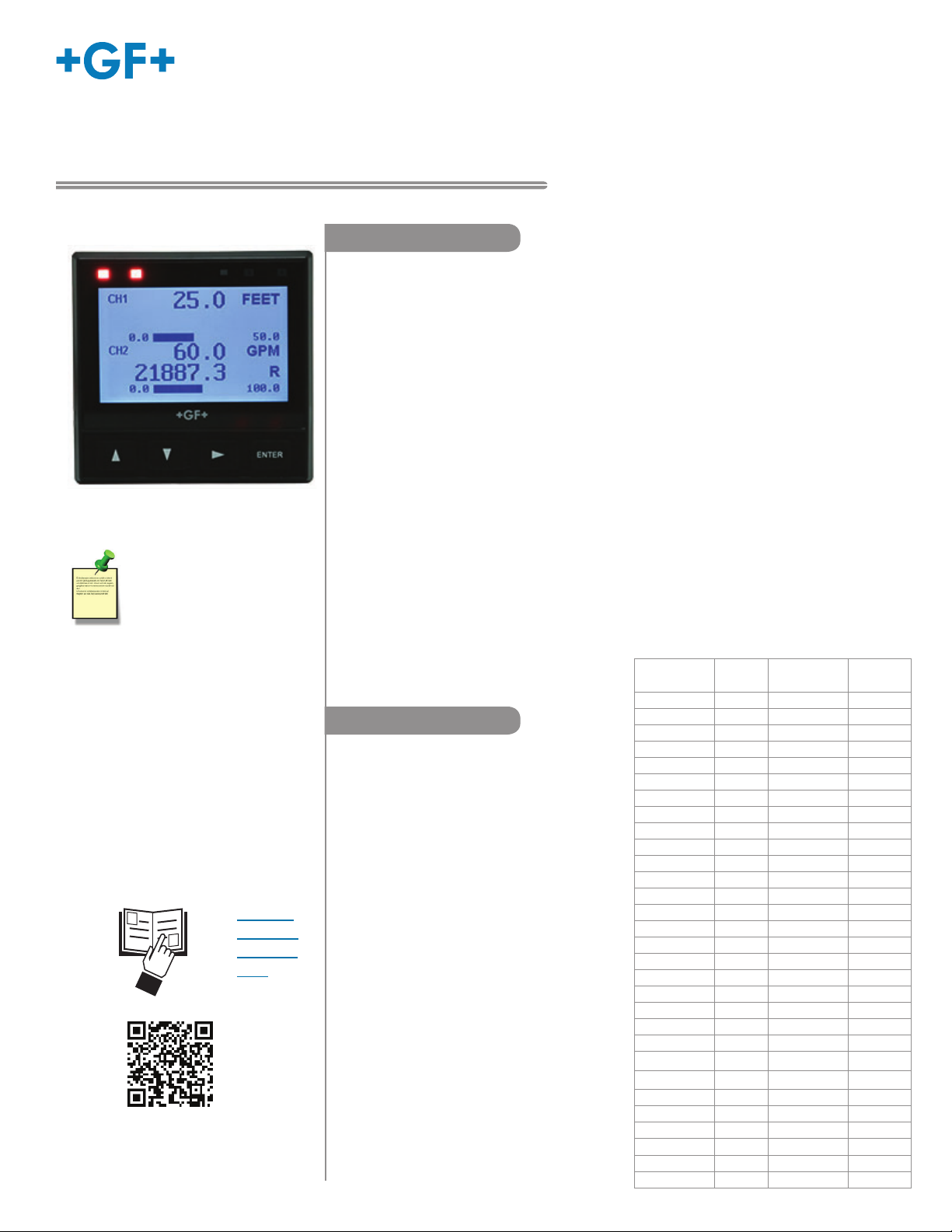
Signet 9950 Dual Channel Transmitter
*3-9950.090*
3-9950.090 Rev. 7 02/19
Description
The 9950 Dual Channel Transmitter is a two channel controller that can support two sensors
of same or different types in one instrument. The sensor types supported by the 9950
are Signet Flow, pH/ORP, Conductivity/Resistivity, Salinity, Temperature, Pressure, Level,
3-9950-1, -2
NOTE:
Prior to installation, Check
www.gfsignet.com for
software updates to your
device. See page 48, Field
Software Update, for more
information.
• English
• Deutsch
• Español
• 中文
Dissolved Oxygen, and devices that transmit a 4 to 20 mA signal with the use of the
8058 iGo
The 9950 includes advanced features such as derived functions, advanced multiple relay
modes, and timer based relay functions. Derived functions allows for the control of a relay
or current loop with the sum, delta (difference), or ratio of two measurements. Multiple
relay modes allow up to three signals to be used for the control of a single relay, and can
be any combination of analog and binary inputs. The timer relay modes allow a relay to be
activated on a repeating basis from every minute to once every 30 days. Weekday timer
mode allows a relay to be energized, on a specifi c day or days of the week at a specifi c
time.
The 9950 supports the following modules:
• Four Channel Mechanical Relay Module
• Two Mechanical and Two Solid State Relay Module
• Two Mechanical Relays and Four Binary Inputs Module
• Direct Single Channel Conductivity Resistivity Module
• Dual Channel 4 to 20 mA Current Loop Output Module
• Dual Channel Conductivity Module
• Modbus Module
Compatibility
The 9950 is compatible with all GF Signet
products listed in the column to the right.
pH and ORP electrodes require the
Signet 2750 or 2751 DryLoc® Sensor
Electronics (sold separately).
Conductivity/Resistivity
measurement requires the Signet
Direct Conductivity Resistivity Module,
Dual Channel Conductivity Module
or 2850 Conductivity/Resistivity Sensor
Electronics (sold separately).
Note: The 9950 is not compatible with the
3-2850-63 Dual Channel 2580 device.
®
Signal Converter.
Operating Instructions (see pg. 11)
Sensor
Model
515/8510 X
525 X
2000 X
2100 X
2250 X
2350 X
2450 X
2507 X
2536/8512 X
2537-5 X
2540 X
2551 XX
2552 XX
U1000 XX
U3000 XX
U4000 XX
2260 X
2270 X
2290 X
2291 X
2610-51 X
2724-2726 X
2734-2736 X
2750/2751 X
2756-2757 X
2764-2767 X
2774-2777 X
2819-2823 X
2839-2842 X
2850 X
Freq
Output
Digital (S3L)
Output
English
Requires
8058-1
Page 2
Start-Up Guide
Safety Information
• Please read entire manual before unpacking, setting up or
operating this equipment. Adhere to all danger, warning and
caution statements. Failure to do so could result in serious
injury to the operator or damage the equipment. Make sure the
protection provided by this equipment is not impaired, do not use
or install this equipment in any manner other than specifi ed in
this manual.
• This unit is designed to be connected to equipment which can
be hazardous to persons and property if used incorrectly.
• Read and understand all associated equipment manuals and
Warning / Caution / Danger
Indicates a potential hazard. Failure to follow all warnings
may lead to equipment damage, injury, or death
Electrostatic Discharge (ESD) / Electrocution Danger
Alerts user to risk of potential damage to product by ESD
Electrocution Danger
Alerts user to risk of potential of injury or death via
electrocution
Personal Protective Equipment (PPE)
Always utilize the most appropriate PPE during installation
and service of Signet products
safety warnings before using with this product.
• Remove power to unit before wiring connections.
• Wiring connections to this product should only be performed by
NOTE / Technical Notes
Highlights additional information or detailed procedure
qualifi ed personnel.
• Do not use unit if front panel is cracked or broken.
3-9950-2
Before commissioning the device, make sure the supply voltage matches the voltage specifi cations on the nameplate. For DC power
input and Loop current regulated voltage, use UL60950-1 or UL61010-1 certifi ed power supply. Power supply shall also be rated
for operation at 4000 m altitude. Provide a suitable switch or circuit breaker the installation. This switch must be located close to
the device (easily reached), and marked as a circuit breaker. The switch or circuit breaker to be used for power disconnect shall be
certifi ed to IEC 60947-1 and IEC 60947-3, per IEC 61010-1, Clause 6.11.4.2. Overcurrent protection (rated > 10 A) is required for the
power cable.
Installation
For future reference, for each installation, it is recommended to record the part number and serial number of each of the
components listed here:
Facility Tag Number or System ID (user assigned):__________________
_
Base unit 3-9950-____ S/N ___________________
Relay Module 3-9950.393-____ S/N ___________________
Single Channel Cond./Resist. Module 3-9950.394-____ S/N ___________________
Dual Channel 4-20 Current Loop Out. Module 3-9950.398-____ S/N ___________________
Dual Channel Conductivity Module 3-9950.394-2 S/N ___________________
Modbus Module 3-9950.395-M S/N ___________________
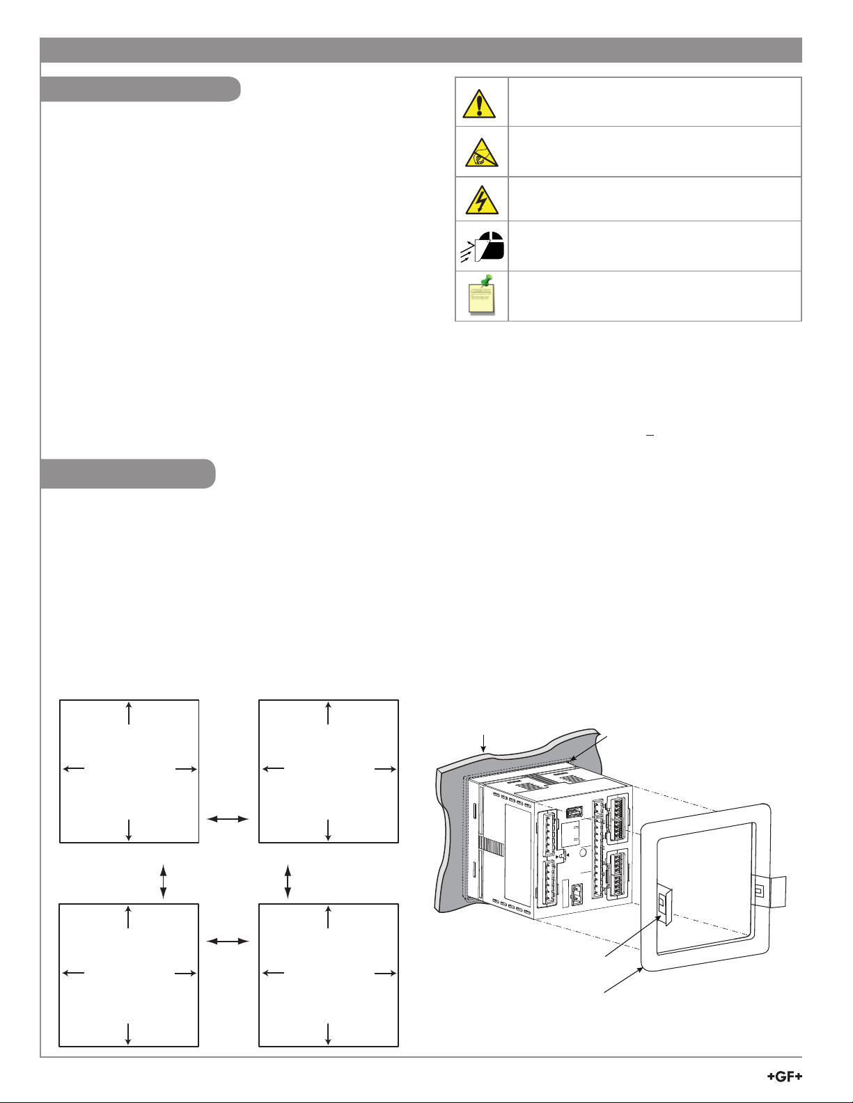
Panel Mount Installation
Panel Cutout
92 x 92 mm
(+ 0.8, - 0 mm)
3.6 x 3.6 in.
(+0.031, -0 in.)
Panel Cutout
92 x 92 mm
(+ 0.8, - 0 mm)
3.6 x 3.6 in.
(+0.031, -0 in.)
Panel Cutout
92 x 92 mm
(+ 0.8, - 0 mm)
3.6 x 3.6 in.
(+0.031, -0 in.)
minimum
clearance
25 mm
(1 in.)
Panel Cutout
92 x 92 mm
(+ 0.8, - 0 mm)
3.6 x 3.6 in.
(+0.031, -0 in.)
panel
gasket on
front side
of panel
MODULE 1
DC POWER
USB
RELAY MODULE
PWR+
PWR–
Loop1+
DC Power
–
12-32 VDC
Loop1
0.50A Max
Loop2+
Loop Voltage
–
12-32 VDC
Loop2
0.03A Max
V+
FREQ
DATA
GND
V+
CH2 CH1
FREQ
DATA
~
N
GND
L
50-60 Hz, 24VA Max
100-240 VAC
Made in U.S. from U.S. and imported parts
MODULE 2
Quick-clip
mounting
bracket
Allowable panel thickness 2.36 mm (0.093 in.) to 33 mm (1.31 in.)
2
9950 Transmitter
Page 3
Start-Up Guide
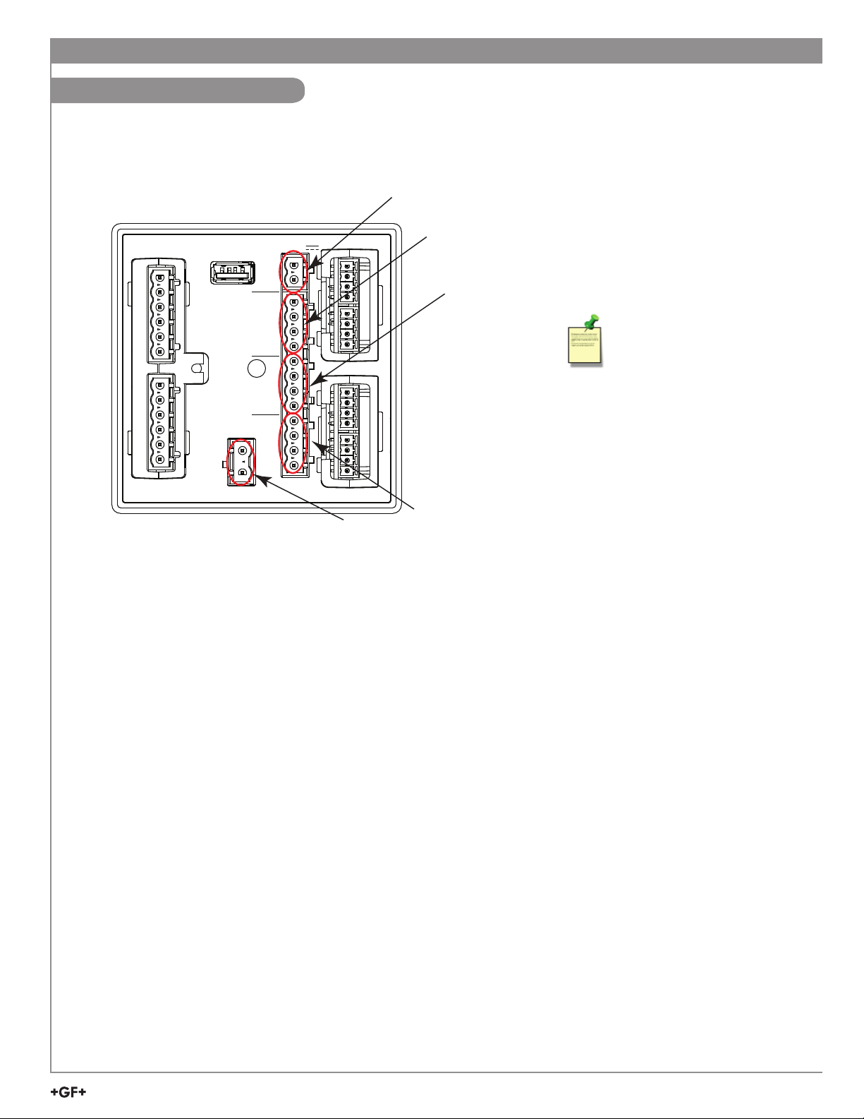
Terminal Identifi cation
Prepare the transmitter installation location. If the back of the transmitter is diffi cult to access when
installed, wire the removable terminal blocks fi rst, then install it completely.
DC Power Terminals
RELAY MODULE
PWR+
PWR–
Loop 1+
Loop 1–
Loop 2+
Loop 2–
FREQ
DATA
GND
CH2 CH1
FREQ
DATA
GND
11-24 VDC
+V
+V
USB
N
L
100-240 VAC~
Made in U.S. from U.S. and imported parts
MODULE 1
MODULE 2
Channel 2 Input
(Frequency/S
AC Power Terminals
Channel 1 Input
(Frequency/S
3
L)
3
L)
The 9950 requires regulated
12 to 32 VDC, ±10% regulated
(24 VDC nominal) or 100240 VAC at 50-60 Hz from an
external power supply
(not supplied).
Maximum current draw is:
500 mA with DC power
24 VA with AC power
DC Power Terminal 3-9950-1 or 3-9950-2
Required by the instrument
• 12 to 32 VDC, ±10% regulated, 0.5 A MAX. DC power input and Loop current regulated voltage require the use of a
UL60950-1 or UL61010-1 certifi ed power supply. Power supply shall also be rated for operation at 4000 m altitude.
Current Loop Outputs 1 and 2
AC Power Terminal 3-9950-2 Only
Required by the instrument
• 100-240 VAC at 50-60 Hz, 24 VA MAX
Relay Module
Dependent on model
• 3-9950.393-1 Four mechanical relays rated at 5A, 250 VAC or 5A, 30 VDC
• 3-9950.393-2 Two mechanical relays, 5A 250 VAC or 30 VDC, and two solid state relays rated at 50 mA, 30 VAC or 30 VDC
• 3-9950.393-3 Two mechanical relays, 5A 250 VAC or 30 VDC, and four binary inputs rated at 6 mA, 10 VDC to 24 VDC
Modules 1 and 2
• 3-9950.394-1 Single Channel Direct Conductivity/Resistivity Module
• 3-9950.398-2 Dual Channel 4 to 20 mA Current Loop Output Module
• 3-9950.394-2 Dual channel Conductivity Module
• 3-9950.395-M Modbus Module
Channel 1 and Channel 2: Digital (S3L)/Frequency Input
• V+: +5 VDC out to sensor (black wire)
• FREQ: Frequency input signal from sensor (red wire)
• S3L DATA: Digital input signal from sensor (red wire)
• GND: Sensor ground (white wire or silver wire from paddle wheel fl ow sensor)
Loop Outputs
• Two Passive 4 to 20 mA current loop outputs 12 - 32 VDC, ±10% regulated (30 mA Max)
• Up to 4 additional Loop Outputs via the Dual Channel 4 to 20 mA Output Module
USB Interface
• Software updates will be provided through the USB port
9950 Transmitter
3
Page 4
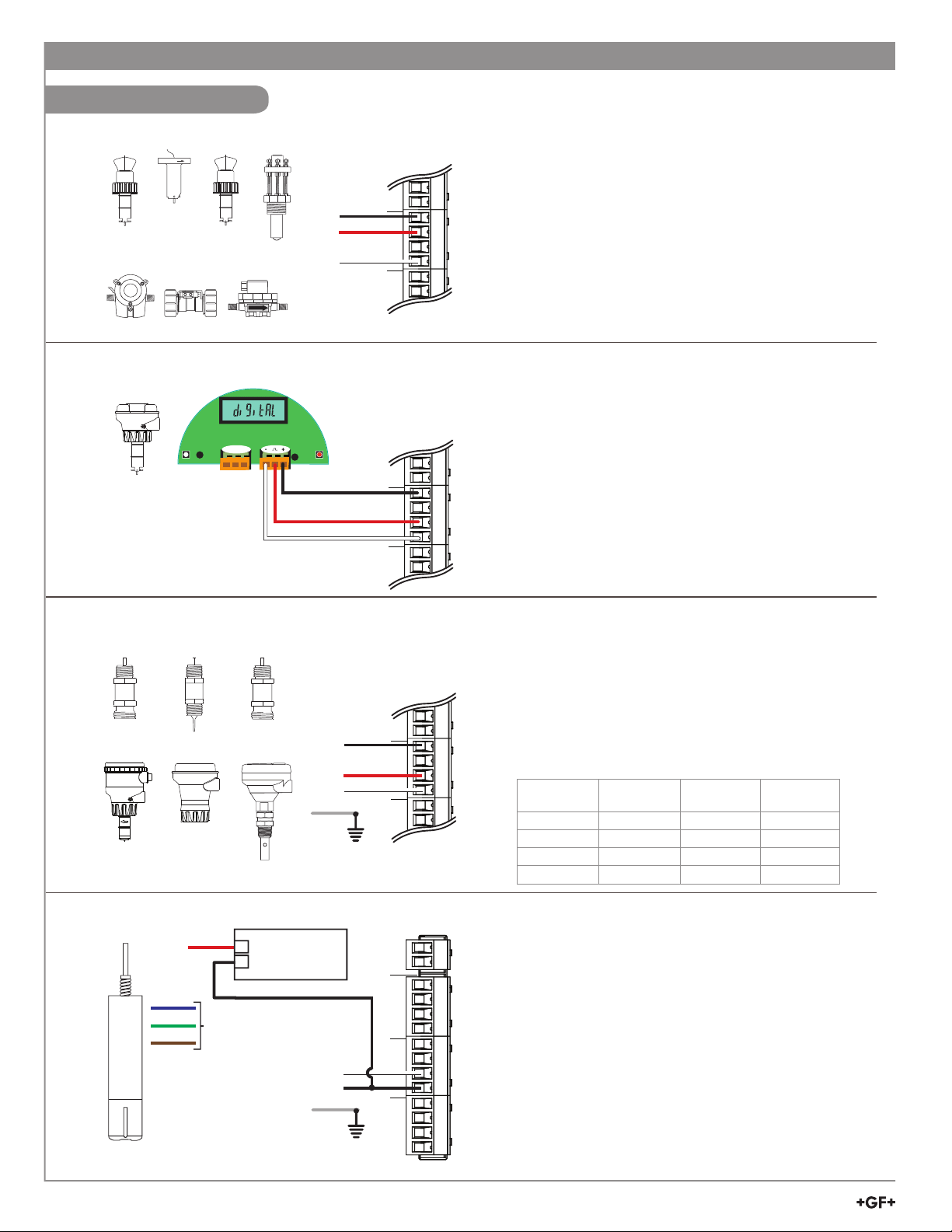
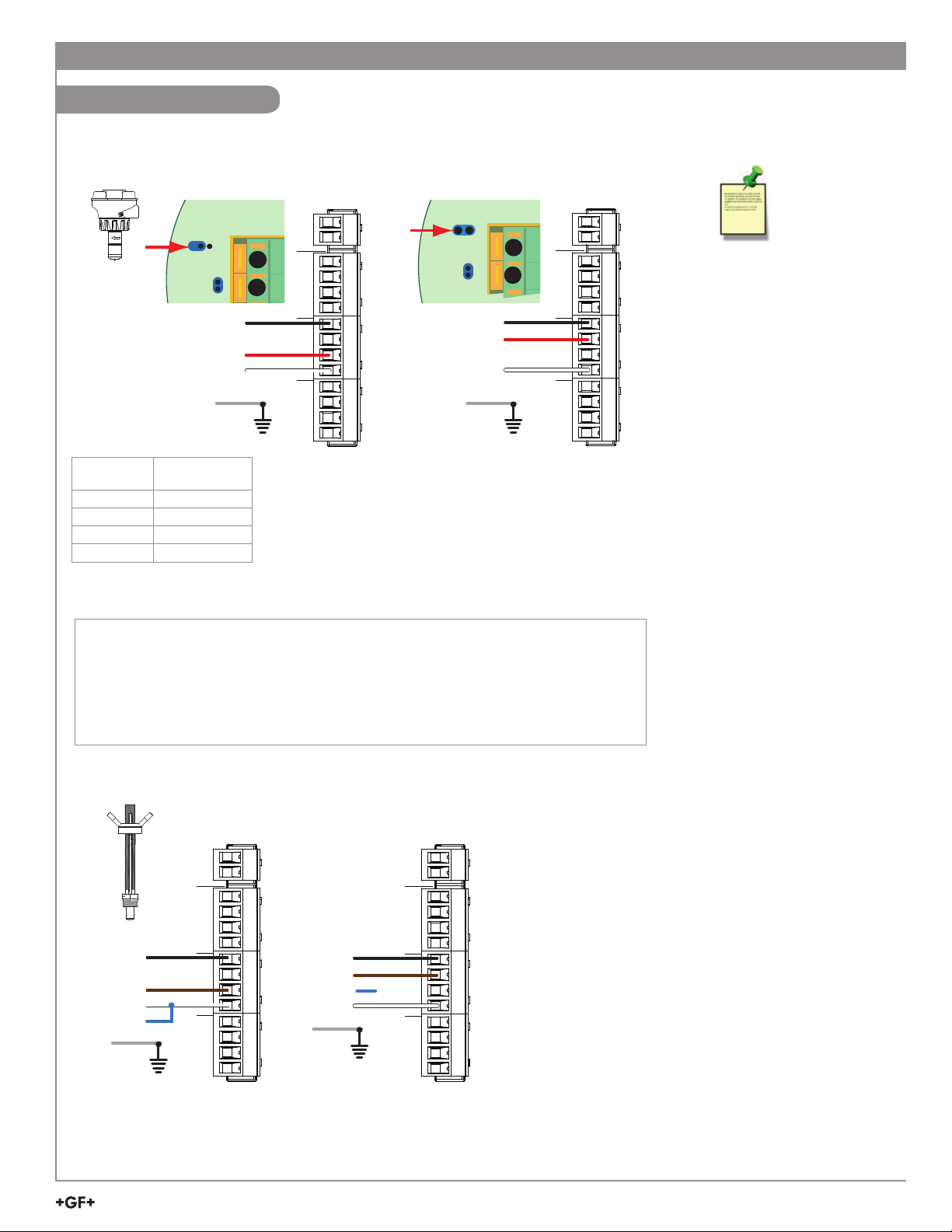
Sensor Wiring
515/8510
525 2536/8512 2540
FLOW
2000 2100 2507
Start-Up Guide
9950 Frequency
DC POWER
Loop
Black
Red
No connection
Silver
FLOW
Loop
+V
FREQ
X
DATA
GND
+V
CH2 CH1
FREQ
+V
FREQ
DATA
GND
Technical Notes:
• See corresponding product manuals for maximum
cable length.
• Maintain cable shield through cable splice.
• Route sensor cable away from AC power lines.
• Select "Yes" to CH # Flow 515/525 when setting up
the input on the 9950. On the 515/8510 and 525
installations, connect the silver (shield) wire to earth
ground in case of EMI noise interference.
2537-5
Blk Red Shld
S1
2250 2350 2450
2551* 2750/2751 2850
* 2551-XX-21, -41
Display Magmeter
NOTE: The 2850 has no SHIELD wire.
9950 S3L Inputs
Technical Notes:
• Wiring terminals on the 2537 are rated for 16 to 22
AWG wires.
DC POWER
-
+
Black
Red
White
S2
No connection
Loop
Loop
+V
X
FREQ
DATA
GND
+V
CH2 CH1
FREQ
+V
FREQ
DATA
GND
• The cable must be 7 mm to 10 mm in diameter
(0.275 in. to 0.394 in.) to seal properly in the
liquid-tight connector.
• The conduit ports have ½ inch NPT threads.
After routing the cables, seal the port with a liquid-tight
conduit connector (3-9000.392-1) or with conduit.
• The 2537 models connect to the 9950 via the
Digital (S3L) output.
Technical Notes:
• Sensor dependent, see sensor manual for maximum
9950 S3L Inputs
cable length.
• Maintain cable shield through cable splice.
DC POWER
• Route sensor cable away from AC power lines.
• Connect the silver (shield) wire to earth ground in case
of EMI noise interference.
• The 9950 is not compatible with the 3-2580-63, dual
channel conductivity device.
Sensor Terminal Connections
Sensor
Terminal
1 +V Shield +V
2 S3L/Freq GND S3L
3 GND S3L GND
4 Not Used +V Not Used
2551 2750/51 2850
Black
No connection
White
Shield
Loop
Loop
+V
X
FREQ
DATA
GND
+V
CH2 CH1
FREQ
+V
FREQ
DATA
GND
3-2610-51
Red
Blue
Green
Brown
+
–
No
connection
Power Supply
12 to 32 VDC
White
Black
Shield
PWR+
PWR–
Loop1+
Loop1–
Loop2+
Loop2–
FREQ
DATA
GND
CH2 CH1
FREQ
DATA
GND
DC POWER
+V
+V
PWR +
PWR –
+V
FREQ
DATA
GND
Technical Notes:
The wiring of the 3-2610-51 is non-standard:
• RED is 12 to 24 VDC (PWR +)
• WHITE is Data
• BLACK is VDC Ground (PWR -)
• A jumper MUST be installed between PWR- and
S3L GND.
NOTE: 3-2610-51 only.
9950 S3L Inputs
4
9950 Transmitter
Page 5
Start-Up Guide
Sensor Wiring
2551-XX-11
Blind Magmeter
Sensor
Terminal
1 Black (+V)
3
S L
Signal
Black
No connection
Red
White
Shield
9950 S3L Inputs
DC POWER
PWR+
PWR–
4
Loop1+
Loop1–
3
Loop2+
Loop2–
+V
X
FREQ
DATA
GND
+V
CH2 CH1
FREQ
DATA
GND
+V
FREQ
DATA
GND
Frequency
Black
Red
No connection
White
Shield
Only in case of EMI interference.
See Frequency Output Technical Notes (2551 & 2552) at right.
2 Red (S3L/Freq)
3 White (GND)
4 Not Used
Input Wiring for 2551 and 2552 sensors
• Either Frequency or Digital (S3L) may be used.
• Signet recommends confi guring these sensors with the Digital (S3L) output to
display reverse fl ow (negative numbers).
• Input type is selected by choosing between “SENSOR FREQ” and "SENSOR S3L" in
the FLOW sensor type INPUT menu (see page 29).
2552
9950 Frequency
PWR+
PWR–
4
Loop1+
3
Loop1–
Loop2+
Loop2–
FREQ
X
DATA
GND
CH2 CH1
FREQ
DATA
GND
DC POWER
+V
+V
+V
FREQ
DATA
GND
2551 Technical Notes:
• When the blue jumper
illustrated here is
placed over both pins,
the 2551-XX-11 (Blind
Magmeter) outputs an
open collector frequency
signal. When the jumper
is removed (or placed
over one pin for storage)
the 2551-XX-11 outputs a
digital (S
3
L)
signal (recommended).
Frequency Output Technical
Notes (2551 & 2552):
• The frequency output will
be displayed as positive
fl ow regardless of the
fl ow direction.
• 5 VDC power required by
the 2551 & 2552 is supplied
by the 9950. No additional
power is required.
• Connect the silver wire
(shield) to earth ground
in case of EMI noise
interference.
Black
No connection
Brown
White
Blue
Shield
9950 S3L Inputs
DC POWER
PWR+
PWR–
Loop1+
Loop1–
Loop2+
Loop2–
+V
X
FREQ
DATA
GND
+V
CH2 CH1
FREQ
DATA
GND
+V
FREQ
DATA
GND
Black
Brown
Blue
White
Shield
No
X
connection
9950 Frequency
DC POWER
PWR+
PWR–
Loop1+
Loop1–
Loop2+
Loop2–
+V
FREQ
DATA
GND
FREQ
CH2 CH1
FREQ
+V
DATA
GND
+V
DATA
GND
2552 Technical Notes:
• The 2552 outputs an open
collector frequency signal that
can be connected to the 9950.
• Route sensor cable away
from AC power lines.
• Connect the silver (shield)
wire to earth ground in case
of EMI noise interference.
9950 Transmitter
5
Page 6
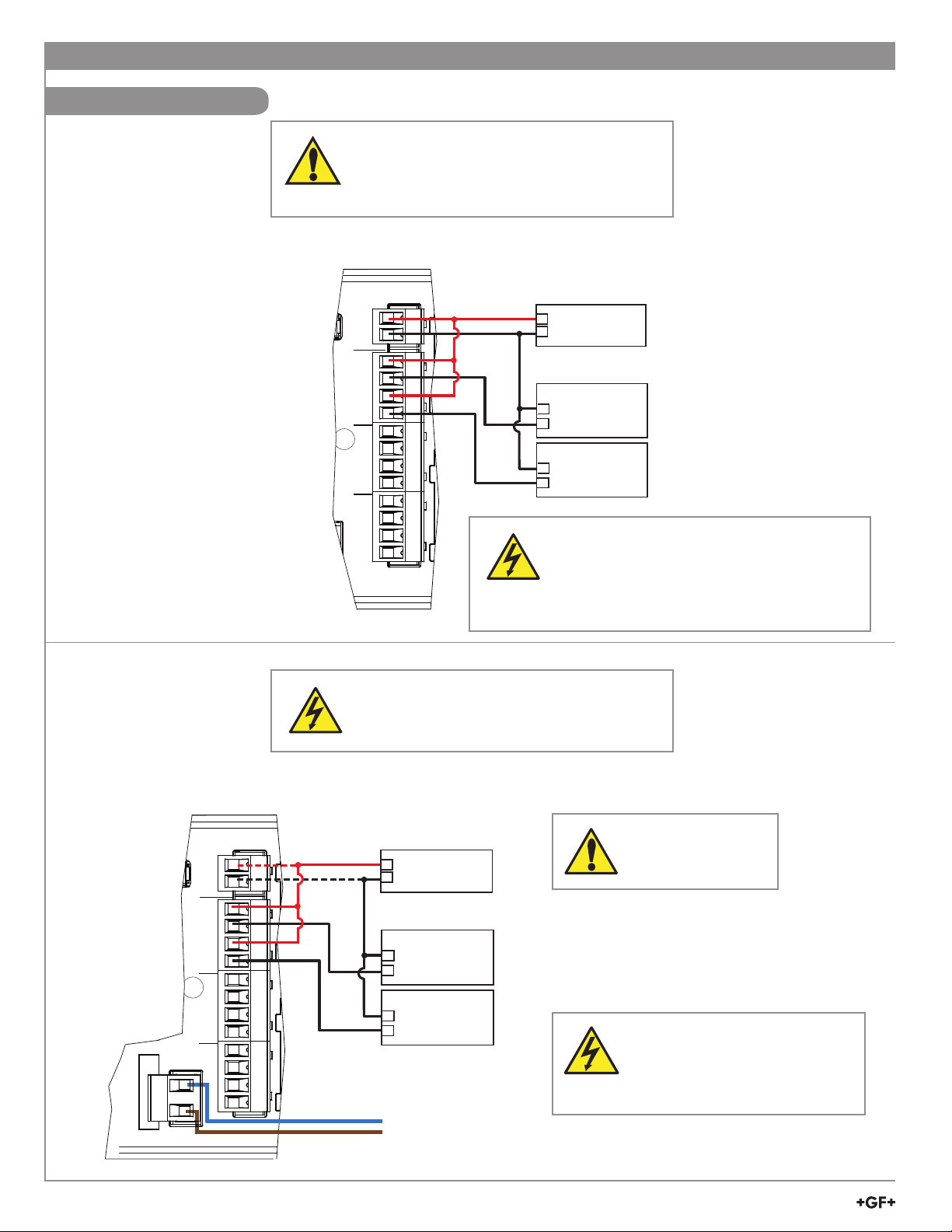
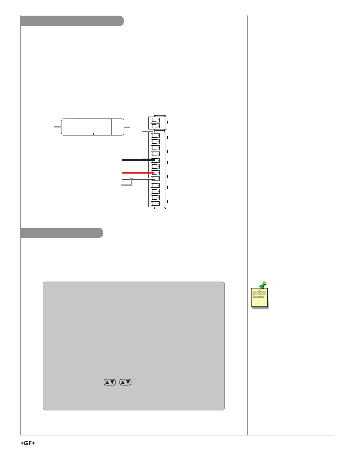
Power Wiring
Start-Up Guide
WARNING
DO NOT connect AC power to the DC version
THE 3-9950-1 MUST BE POWERED BY
12 - 32 VDC at 0.5 A.
3-9950-1 and 3-9950-2
DC POWER
PWR+
PWR–
Loop1+
Loop1–
Loop2+
Loop2–
FREQ
DATA
GND
CH2 CH1
FREQ
DATA
GND
and imported par
Red
Red
+V
+V
Red
Black
Black
Black
+
Power Supply
–
12 to 32 VDC
PLC or Recorder
–
Loop Input
+
4 to 20 mA
PLC or Recorder
–
Loop Input
+
4 to 20 mA
Caution:
For DC power input and loop current regulated
voltage, use UL60950-1 or UL61010-1 certifi ed
power supply. Power supply shall also be rated
for operation at 4000 m altitude.
DC POWER
PWR+
PWR–
Loop1+
Loop1–
Loop2+
Loop2–
+V
FREQ
DATA
GND
+V
CH2 CH1
FREQ
N
100-240 VAC~
50-60 Hz, 24VA Max
Made in U.S. from U.S. and imported par
DATA
GND
L
DC power optional
Red
Red
Caution:
Electrical shock hazard exists!
Never connect live AC lines to the instrument.
3-9950-2
Red
Black
Black
Black
Neutral
Line
+
Power Supply
–
12 to 32VDC
PLC or Recorder
–
Loop Input
+
4 to 20 mA
PLC or Recorder
–
Loop Input
+
4 to 20 mA
100-240 AC
External DC Power is
required for the current
loops.
CAUTION
Keep AC power separate from
sensor and signal wiring to prevent
interference and damage to the
9950 Transmitter.
6
9950 Transmitter
Page 7

Start-Up Guide
Relay Module Wiring
• Terminals accept 12 to 24 AWG wire.
• Strip 10 to 12 mm (0.4 to 0.5 in.) of insulation from wire tips and tin bare ends to eliminate fraying.
• Insert wire tip or ferrule completely into the terminal and secure with the screw.
• Do not allow any AC leads that may be connected to the internal relays to come in contact with low voltage wiring.
3-9950.393-1 and 3-9950.393-2
Relay 1: The alarm is OFF during normal operation, and will
go ON when relay energizes according to 9950
Relay settings.
Relay 4: The valve is ON during normal operation, and will
go OFF when relay energizes according to 9950
Relay settings.
NO = normally open (closes when energized)
NC = normally closed (opens when energized)
Mechanical Relays Rating: 5A 250 VAC, 5A 30 VDC
Solid State Relays Rating: 50 mA 30V AC/DC
(for 309950.393-2 relay 1 & 2)
3-9950.393-3
The alarm is OFF during normal operation, and will go ON when the
relay energizes according to 9950 Relay settings.
Binary input 4 will be ON when the tank level is above the level
switch, Binary Input 4 will be OFF when the tank level is below the
level switch.
Binary Input Ratings
Maximum Input voltage
(without damage)
Minimum Input voltage
(without damage)
Maximum input voltage for
signal “Off” (low or "0")
30 VDC
-5 VDC
(no operation below 0 VDC)
1.5 VDC
Minimum input voltage
for signal “On” (high or "1")
Maximum current draw for
signal “0” (low)
Minimum current draw
for signal “1” (high)
Typical current draw
for signal “1” (high)
3.0 VDC
<500 ADC
500 A
6.0 mA at 30 VDC, 4.8 mA at 24 VDC,
2.4 mA at 12 VDC, 1.0 mA at 5 VDC
3-9950.393-1
NO 1
RELAY 1
RELAY 2
RELAY 3
RELAY 4
3-9950.393-3 Internal Power
RELAY 1
RELAY 2
No Connection
BINARY INPUT 1
BINARY INPUT 2
BINARY INPUT 3
BINARY INPUT 4
3-9950.393-3 External Power
RELAY 1
RELAY 2
No Connection
BINARY INPUT 1
BINARY INPUT 2
BINARY INPUT 3
BINARY INPUT 4
N/C 1
COM 1
NO 2
N/C 2
COM 2
NO 3
N/C 3
COM 3
NO 4
N/C 4
COM 4
AC or DC
Flow
9950.393 Internal Power
N/O 1
N/C 1
COM 1
N/O 2
N/C 2
COM 2
X
SW1
SW2
SW3
SW4
SW COM
9950.393 External Power
N/O 1
N/C 1
COM 1
N/O 2
N/C 2
COM 2
SW1
SW2
SW3
SW4
SW COM
DC power
+
power
X
-
Level Switch
Level Switch
ALARM!
AC or DC
power
ALARM!
AC or DC
ALARM!
Valve
power
Level
AC or DC
power
Level
Power
Switch
INT
EXT
EXT
If an externally powered sensor is connected with the
3-9950.393-3 module, set the power switch to the EXT
position. The module can power external sensors by
switching the power switch to the INT position. Maximum
INT
power that can be drawn from the module is 6mA at 30 VDC.
9950 Transmitter
7
Page 8
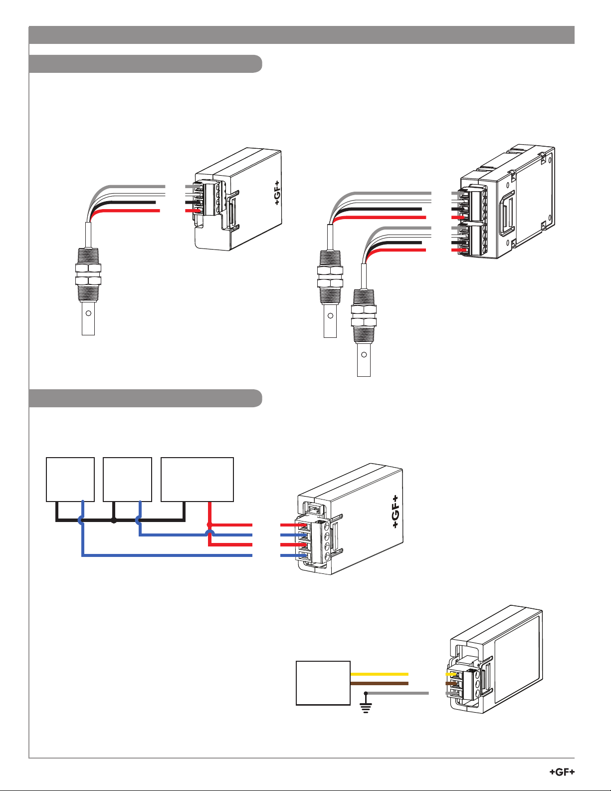
Conductivity Module Wiring
Start-Up Guide
Single Channel
Conductivity Module
Dual Channel
Conductivity Module
Loop Wiring
PLC
or
Recorder
–
+
Shield
White
Black
Red
PLC
or
Recorder
–
+
SHLD
TEMP
ISO GND
SIGNAL
Power
Supply
–
SHIELD (silver)
TEMP (white)
ISO GND (black)
SIGNAL (red)
3-9950.394-1
Single Channel Cond.
Shield
White
Black
Red
shield
White
Black
Red
ISO GND
ISO GND
SHLD
TEMP
SIGNAL
SHLD
TEMP
SIGNAL
Dual Channel
4 to 20 mA Module
+
Loop A+
Loop A–
Loop B+
Loop B–
Loop A +
Loop A Loop B +
Loop B -
3-9950.398-2
Dual Channel 4-20mA
Modbus Module
RS485
RCVR
+
–
PLC
8
9950 Transmitter
Yellow
D1 + RS485
Brown
(Optional) Shield
D0 + RS485
GND
Shield recomended in
noisy environment
Page 9
Start-Up Guide
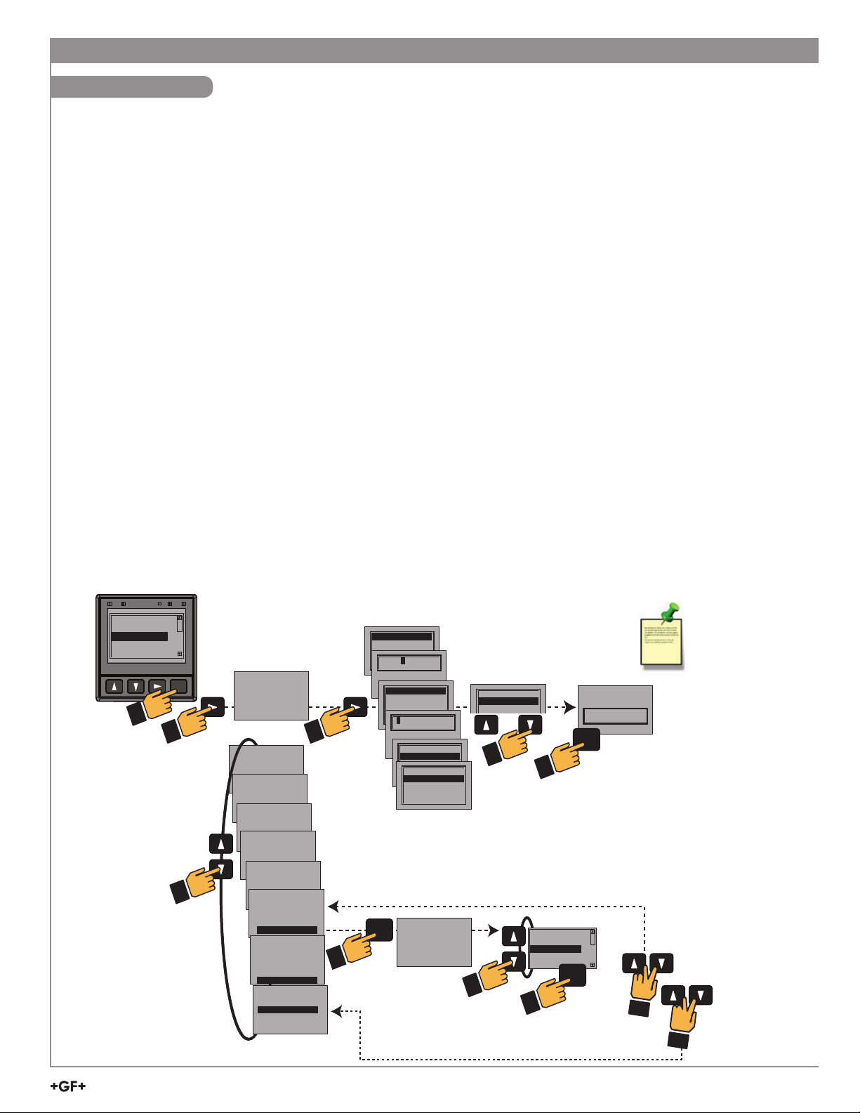
Operation
Keypad Functions
The four buttons of the keypad ( ENTER) are used to navigate display modes according to the descriptions in this table.
Notice the function of each button may change depending on the display mode.
This menu operation sets up the 9950 for basic function:
1. Select desired language using the [UP] and [DOWN] arrows.
Press ENTER to save.
2. Press to select the TIME FORMAT.
Press or to select 24 hour or AM/PM.
Press ENTER to save the format selection.
3. Press the move to the next selection, SET TIME.
Press to scroll through hours, and minutes place values.
Use or to adjust the value.
Press ENTER to save the time selection.
4. Press to move to the next selection, SET DATE FORMAT.
Press to select the MM/DD/YYYY date format and or to
scroll through other format options.
Press ENTER to save the date format selection.
5. Press to move to the next selection, SET DATE.
Press to scroll through the days, months, and years.
Use or to adjust the number, and to select the next
number.
Press ENTER to save the Date selection.
6. Press to move to the next selection,
SET DECIMAL MARK.
Press and use or to highlight desired decimal separator
(comma or decimal mark).
Press ENTER to save the decimal mark selection.
4
ENGLISH
FRANÇ
DEUTCH
ESPAÑOL
中文
ENTER
TIME FORMAT
24 HOUR
TEXT 3
SET TIME
08:56:47
DATE FORMAT
TEXT 3
MM/DD/YYYY
SET DATE
TEXT 3
02/25/2016
SET DECIMAL MARK
TEXT 3
999.99
SELECT UNITS
TEXT 3
U.S. CUSTOMARY
SETUP
TEXT 3
CHANNEL 1
PRESS ENTER
3
SETUP
CHANNEL 2
PRESS ENTER
PRESS ENTER
EXIT STARTUP
24 HOUR
AM/PM
GERMAN
LANGUAGE
00:00:040
LANGUAGE
AM/PM
MM/DD/YYYY
DD/MM/YYYY
YYYY/MM/DD
LANGUAGE
LANGUAGE
ENTER
09:11:04
02/25/20162
AM/PM
99.999
99,999
METRIC
U.S. CUSTOMARY
02/25/2016
LOOKING FOR
SENSOR TYPE
TEXT 3
7. Press to move to the next selection, SELECT UNITS.
Press and scroll or to choose Metric or
U.S. Customary.
Press ENTER save unit selection.
8. Press to move to the next selection SETUP CHANNEL 1.
Press ENTER, ('Looking for Sensor Type' will appear on
the screen).
The 9950 will search for an attached S
3
L sensor on
Channel 1. The found sensor type will be highlighted.
If your desired sensor is not highlighted, use the
or to scroll through the sensor list and select another
sensor type.
Press ENTER to save sensor type selected.
Press or to access screens to adjust common
sensor parameters.
= edit, ENTER = Save, += Cancel.
Press + to return to SETUP CHANNEL 1 screen.
9. Press to move to the next selection, SETUP CHANNEL 2.
Repeat steps in number 8 to set up Channel 2.
Press to go back to Channel 1, if desired.
When done, press + together one time exits to the
previous menu. Press + together a second time to exit
Easy Start Up.
Easy Set Up can be
entered by setting
either or both channels
to Factory and cycling
MM/DD/YYYY
DD/MM/YYYY
YYYY/MM/DD
OR
NONE
FACTORY
FLOW
pH
ORP
100% SOLUTION
ENTER
saves
changes
ENTER
saves
changes
DATE FORMAT
NAME
SAVING
power on the 9950.
9950 Transmitter
9
Page 10
Start-Up Guide
Password
Password Overview
The password is required to start editing. Once entered correctly, this password will not be needed for subsequent uses, until the
menu system is exited. The password will be required when the menu system is re-entered.
Your choice of password (STD or CODE) is selected in the Options Mode.
STD
The standard (STD) password is , pressed in sequence. This password is designed to protect the 9950 from
unintentional changes. It is best suited for systems where a group of people need to be able to change settings.
CODE
The CODE default setting is 0000, adjustable to any 4-digit numerical code up to 9999. Using a personal code provides the
maximum degree of security. This code can be modifi ed in the Options mode.
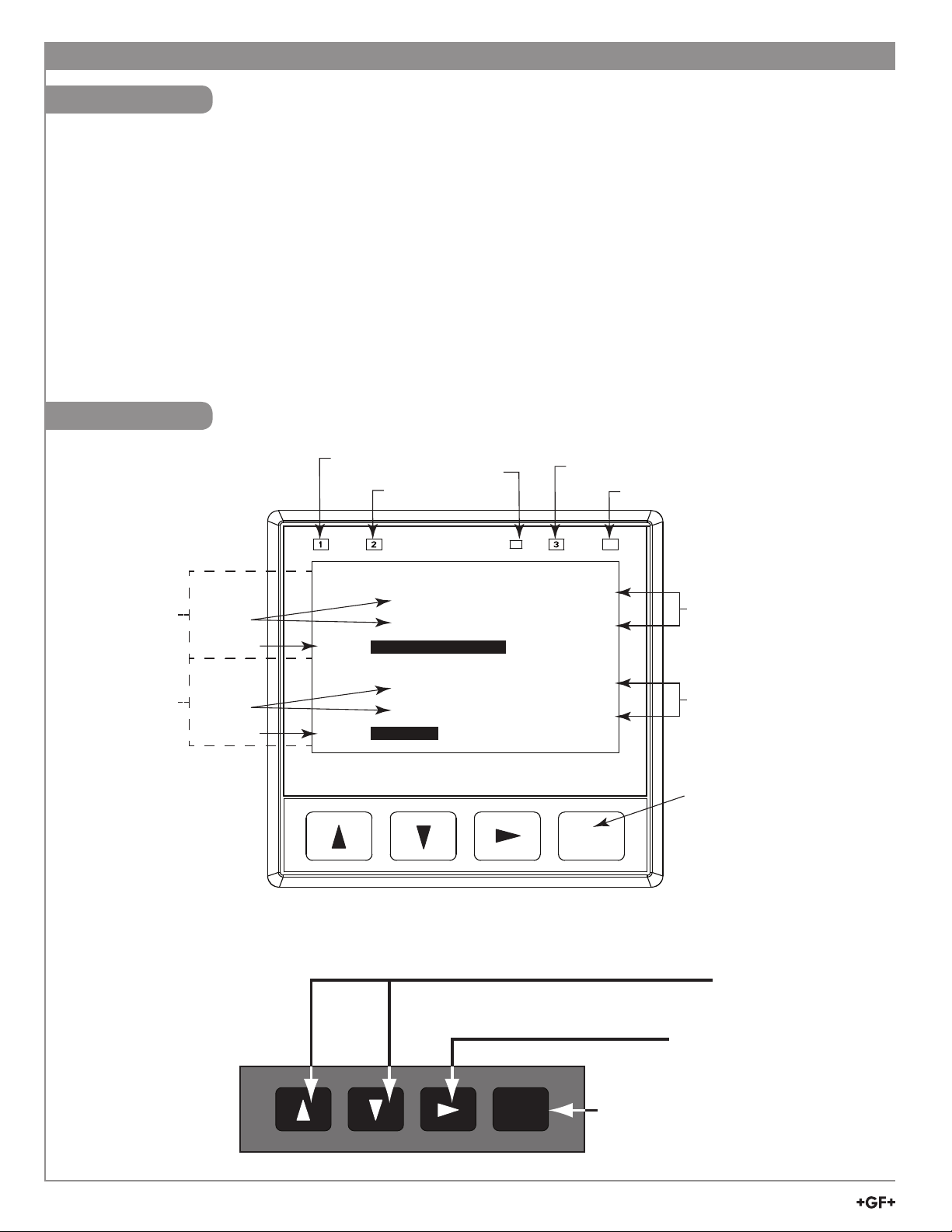
Operation
Channel 1
display area
Channel 2
display area
Numeric
Values
or labels
Bar Graph
Numeric
Values
or labels
Bar Graph
Relay 1
Indicator LED
CH1
00.00
CH2
0 0.0 0
Backlight Sensor
(do not block)
Relay 2
Indicator LED
9999.9
9999.9
9999.9
9999.9
Relay 3
Indicator LED
UOM
UOM
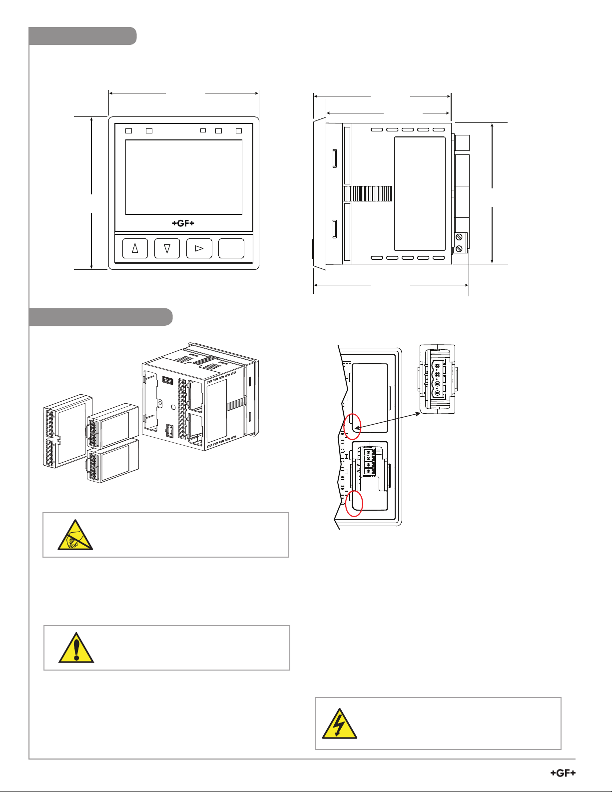
9 9.9 9
UOM
UOM
9 9.9 9
ENTER
Relay 4
Indicator LED
4
Units of Measure
(GPM, pH, sec, %, etc.)
Units of Measure
(GPM, pH, sec, %, etc.)
Menu Navigation Keys
10
9950 Transmitter
UP, DOWN keys
Scroll through Menu options or adjust values during editing
Press both together to exit a menu or escape without saving
RIGHT key
Select item or character to edit
ENTER
ENTER key
Access menus
Save changes
Page 11

Operating Instructions
Warranty Information Table of Contents
Refer to your local Georg Fischer Sales offi ce for the
most current warranty statement.
All warranty and non-warranty repairs being returned
must include a fully completed Service Form and
goods must be returned to your local GF Sales offi ce or
distributor.
Product returned without a Service Form may not be
warranty replaced or repaired.
Signet products with limited shelf-life (e.g. pH, ORP,
chlorine electrodes, calibration solutions; e.g. pH buffers,
turbidity standards or other solutions) are warranted out
of box but not warranted against any damage, due to
process or application failures (e.g. high temperature,
chemical poisoning, dry-out) or mishandling (e.g. broken
glass, damaged membrane, freezing and/or extreme
temperatures).
Product Registration
Thank you for purchasing the Signet line of Georg
Fischer measurement products.
If you would like to register your product(s), you can now
register online in one of the following ways:
• Visit our website www.gfsignet.com.
Under Service and Support click Product
Registration Form
• If this is a pdf manual (digital copy), click here
General Information .........................................................1
Safety Information/Installation..........................................2
Terminal Identifi cation ......................................................3
Wiring ........................................................................... 4-8
Sensor Wiring ......................................................... 4-5
Power Wiring ..............................................................6
Modules Wiring ...................................................... 7-8
Operation .........................................................................9
Password .................................................................10
Keypad Operation ....................................................10
Warranty Information ................................................11
Product Registration ................................................11
Dimensions ..............................................................12
Module Installation ...................................................12
Plug-In Modules .............................................................13
Relay Modules ...............................................................13
Conductivity Loop and Modbus Modules ......................14
Signal Type: Frequency ................................................14
Signal Type: Digital (S
3
L) ..............................................14
Signal Type: 4 to 20 mA ................................................15
Relay Functions .............................................................15
Relay Modes ...................................................... 16-19
Derived Functions ....................................................20
Menu System .................................................................21
Common Menus ....................................................... 22-28
Loop Menus .............................................................22
Relay Menu ........................................................ 23-25
Option Menu ....................................................... 25-27
View Mode ......................................................... 27-28
Sensor-Specifi c Menus ............................................ 29-50
Flow .................................................................... 29-30
pH ....................................................................... 31-33
ORP .................................................................... 34-35
Conductivity/Resistivity ...................................... 36-38
Pressure ............................................................. 39-40
Level/Volume ...................................................... 41-43
Temperature .............................................................44
4 to 20 mA .......................................................... 45-46
Salinity ................................................................ 47-48
Dissolved Oxygen .............................................. 49-50
Field Software Update ...................................................51
Updating the 9950 ..........................................................51
Troubleshooting ....................................................... 52-53
Appendix .................................................................. 54-67
Averaging .................................................................54
LOG Current Loop Output .......................................54
Custom Measurements ...................................... 55-58
Calibration Procedures - pH............................... 59-60
Calibration Procedure - ORP ............................. 61-62
Calibration Procedure - Conductivity/Resistivity ......63
Calibration Procedure - Flow ...................................64
Calibration Error Messages .....................................65
USP Limits ................................................................66
Modbus ....................................................................66
Modbus Communication Setting Menus ..................67
Maintenance .............................................................67
Map of 9950 Relay and Loop Sources ....................68
Specifi cations ........................................................... 69-70
Notes ..............................................................................71
Ordering Information ......................................................72
9950 Transmitter
11
Page 12
Dimensions
y
3-9950-1/-2
99.06 mm
(3.90 in.)
12 34
Side ViewFront View
90.73 mm
(3.57 in.)
82.60 mm
(3.25 in.)
99.06 mm
(3.90 in.)
Module Installation
ENTER
9950
MODULE 1
MODULE 2
102.37 mm
(4.03 in.)
Dual Channel
4 to 20 mA Module
Rounded
Corners
Important!
Ensure the rounded
corner of the module is
alligned with the rounded
corner of the module slot
before installing
91.44 mm
(3.60 in.)
CAUTION
Avoid Electrostatic Discharge (ESD).
The plug-in modules may be installed either before or after the
base unit is mounted. If the 9950 Base Unit will be mounted
using the provided quick clip mounting bracket, install plug-in
modules fi rst with power disconnected.
CAUTION
Exercise care when installing modules.
Do not bend connecting pins.
To install modules:
Remove power from the 9950. Carefully align pins and
connectors (do not bend connecting pins) and push module fi rmly
into place, then attach with screw(s) for Relay Modules only.
Note: Modules can be installed in either slot.
12
9950 Transmitter
Shown with Single Channel
Conductivit
Module installed in Module Slot 2
To move modules:
Remove power from the 9950.
For Relay Modules:
Unplug connectors, remove screw(s), and carefully pull
module straight out from the base unit. Do not bend the
connecting pins.
For Conductivity, Dual Channel 4 to 20 mA, and Modbus
Modules:
Unplug connectors and squeeze the two retaining tabs while
pulling module out of 9950.
WARNING
Relays may be connected to external
high-voltage power sources or multiple power
sources creating an electrocution hazard.
Page 13
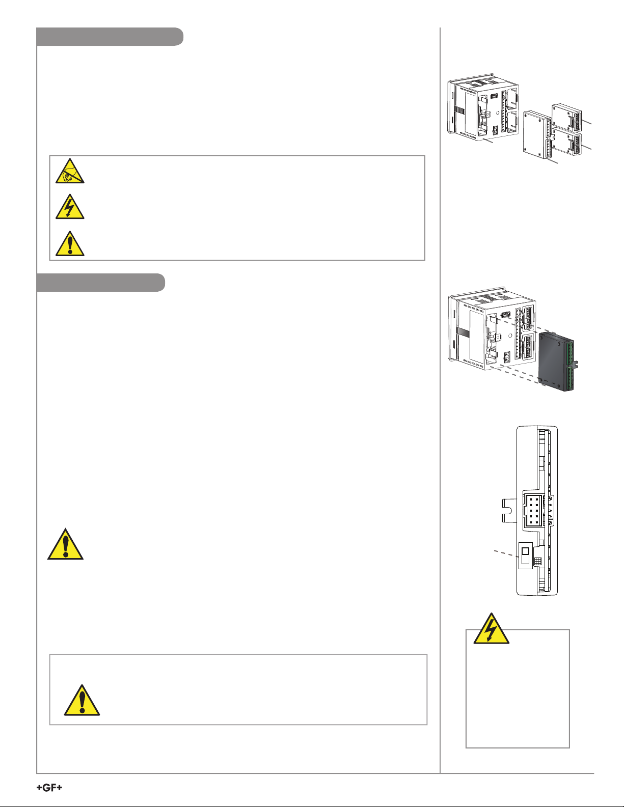
Plug-In Modules
a
bcd
Optional modules and accessories are available for the 9950:
a. Base Unit (required)
b. Optional Relay Module
c. Optional Module 1
d. Optional Module 2
Each item is ordered separately. Modules are fi eld-replaceable at any time.
See Module Installation (pg. 11) and Ordering Information (pg. 68) sections for more details.
CAUTION
Avoid Electrostatic Discharge (ESD).
•
Minimize handling of the plug-in modules to reduce the possibility of damage due to ESD.
•
Handle modules by the edges.
Never touch any exposed circuitry or contacts.
•
Wear an anti-static wristband or stand on an anti-static mat, or keep one hand touching a
properly grounded pipe or other piece of properly grounded metal when handling modules.
Relay Modules
Mfr. Part No. Code Description
3-9950.393-1 159 310 268 Relay Module - 4 Mechanical Relays
3-9950.393-2 159 310 269 Relay Module - 2 Mechanical Relays, 2 Solid State Relays
3-9950.393-3 159 310 270 Relay Module - 2 Mechanical Relays , 4 Binary Inputs
The 9950 has a slot for an optional Relay Module for any of the modules listed above.
• Dry-contact relays are electromechanical switches with a moving contact armature. They are
suitable for many general-purpose applications, AC or DC, including AC loads up to 250 V.
• Solid-state relays are electronic switches with no moving parts. They may be used with AC
or DC loads, but have lower current handling capability and voltage ratings than Dry-contact
relays. Solid-state relays will outlast Dry-contact relays in pulsing applications. 30 VDC/ VAC
maximum.
• The four Binary Inputs can detect if an external sensor or switch is open or closed. The switch
state can be used to control the relays in the module
relay activation and are not considered an input measurement.
. The four binary inputs only control
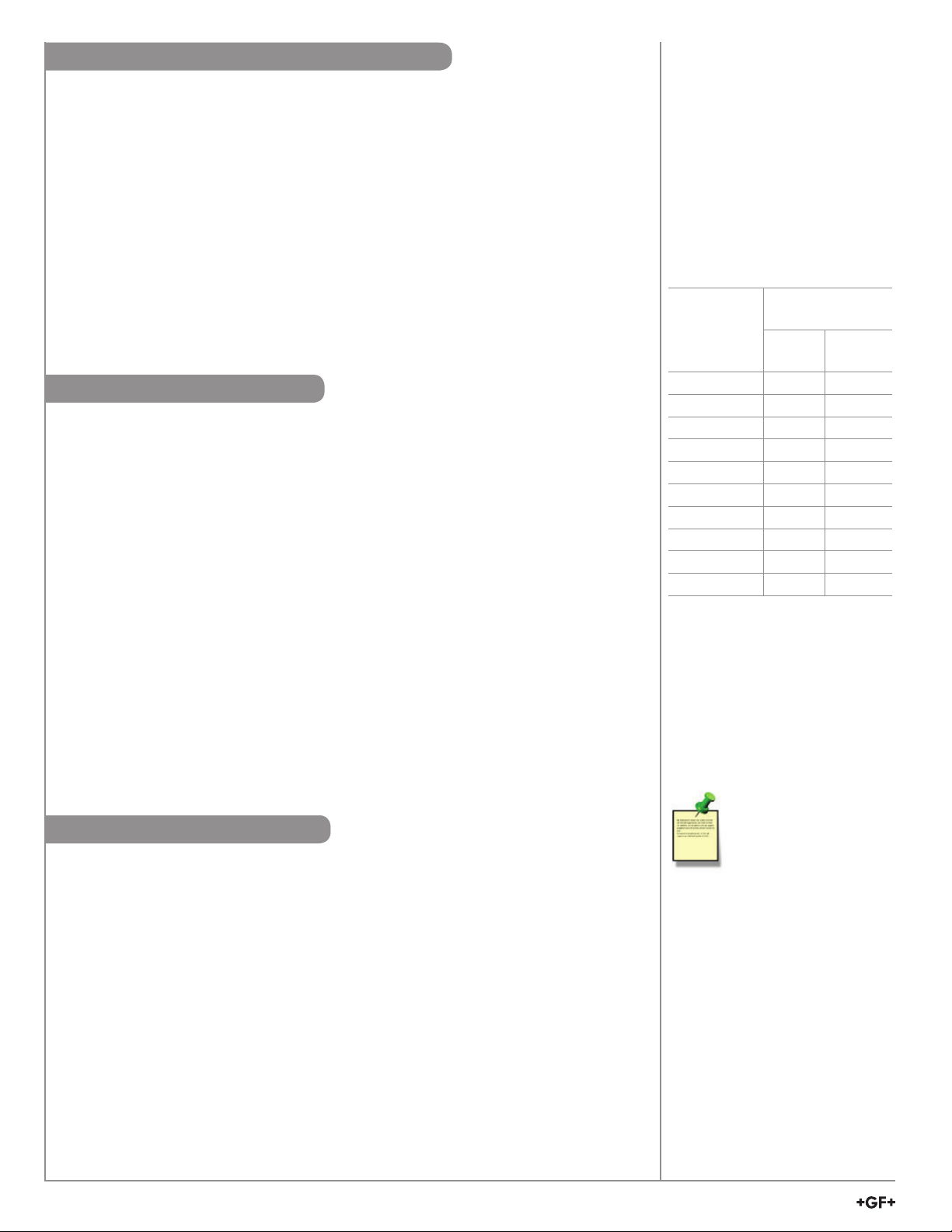
3-9950.393-3
For wiring information, refer to the Relay Wiring section, page 7.
The 3-9950.393-3 module can be set to supply power to the external switch/
sensor. For switches/sensors that require power set the Int/Ext switch to the Int
positions. If the external Switches/Sensors are powered set the Int/Ext switch to
Ext. Important for externally powered switches/sensors ensure the output signal is
within the allowable range for the 3-9950.393-3.
Int / Ext
Switch
EXT
INT
NOTE:
• The four red Indicator LEDs on the front panel of the 9950 show the status of relays
1, 2, 3, & 4. The LEDs will activate with or without a relay module installed.
• Hysteresis and time delay are adjustable for each relay.
CAUTION
CAUTION
Switching active loads (usually inductive) can cause contact arcing suffi cient
to damage the relays.
The RC Filter Kit or “snubber” (part number 3-8050.396) is available as an
accessory to reduce or eliminate these damaging effects. Recommended for
inductive loads greater than 50 VAC (remote relays, solenoids, pumps, etc.)
Keep relay wiring
separate from sensor
and signal wiring to
prevent interference
and damage to the
9950 Transmitter.
9950 Transmitter
13
Page 14
Conductivity, Loop and Modbus Modules
Mfr. Part No. Code Description
3-9950.394-1 159 001 894 Single Channel Direct Conductivity Resistivity Module
3-9950.394-2 159 001 847 Dual Channel Conductivity Module
3-9950.398-2 159 001 848 Dual Channel 4 to 20 mA Current Loop Output Module
3-9950.395-M 159 001 905 Modbus Module
Direct Conductivity Resistivity Module
Compatible with all GF Signet Conductivity Electrodes. Maximum Conductivity cable
length is 30 meters (100 feet). For longer distances use the 3-2850 Conductivity Sensor
Electronics. Up to two modules can be installed in a 9950 Transmitter.
Dual Channel 4 to 20 mA Module
Two additional 4 to 20 mA passive current loop outputs in a single module, allows up to
six current loop modules in the 9950 Transmitter.
Modbus Module
The Modbus Module connects the 9950 to serial RS485 Modbus automation networks.
Signal Type: Frequency
Signet fl ow sensors 515/8510, 525, 2000, 2100, 2507, 2536/8512 and 2540 provide a
frequency output. (Flow sensors 2537, 2551 and 2552 can be confi gured with either
Digital (S
The maximum allowable cable length for sensors with frequency output is dependent upon
the output signal strength of the sensors themselves, and the degree to which the signals
are susceptible to EMI or "noise." This is largely a function of whether the sensors are
self-powered (515/8510 and 525), or powered by an external source (-1).
3
L) or Frequency outputs).
• The input terminals on the 9950 carry frequency data signals from the sensor.
• The 9950 has a selection for 515/525 under the input menu. Select "Yes" for optimum
signal performance.
• Do not route sensor or output cables in conduit containing AC power wiring.
Electrical noise may interfere with sensor signal.
• Routing cable in grounded metal conduit will help prevent electrical noise and
mechanical damage.
• Seal cable entry points to prevent moisture damage.
• Only one wire should be inserted into a terminal. Splice double wires outside the
terminal.
• In case of noise interference, ground the sensor SHIELD wire to a local earth ground
at a point near the sensor.
• Consult the sensor manual for additional wiring information.
Flow sensor
models with
Frequency
Output
515/8510 X
525 X
2000 X
2100 X
2507 X
2536/8512 X
2537 X
2540 X
2551 X
2552 X
Maximum
Cable Length
60 m
(200 ft)
305 m
(1000 ft)
Signal Type: Digital (S3L)
• The input terminals on the 9950 carry Digital (S3L) serial data from the sensor.
• Do not route sensor or output cables in conduit containing AC power wiring.
Electrical noise may interfere with sensor signal.
• Routing cable in grounded metal conduit will help prevent electrical noise and
mechanical damage.
• Seal cable entry points to prevent moisture damage.
• Only one wire should be inserted into a terminal. Splice double wires outside the
terminal.
• The TOTAL cable length from I/O devices to the transmitter must not exceed
305 m (1000 ft).
• In case of noise interference, ground the sensor SHIELD wire to a local earth ground at
a point near the sensor.
• Consult the sensor manual for additional wiring information.
• The maximum cable length of the Digital (S
of sensors connected and the size of the conductors in the cable. For best results,
determine the maximum cable length for the system before routing cables.
14
9950 Transmitter
3
L) bus varies depending on the types
In case of noise
interference, connect
the cable shield to earth
ground.
Maximum total cable length
of the Digital (S3L) Bus:
The quality of the cable used
in the bus determines the
maximum length.
The maximum cable length
may not exceed
305 m (1000 ft),
regardless of current
requirements.
Page 15
Signal Type: 4 to 20 mA
When connecting a non-Signet sensor to the 9950, the sensor’s 4 to 20 mA signal must be
converted to Digital (S
and converts it into Digital (S
1. Wire the 8058 between the 4 to 20 mA loop source and the 9950 Digital (S
3
L). The 8058 i-Go Signal Converter accepts any 4 to 20 mA signal
3
L).
3
L) input
terminals.
2. In the 9950 INPUT menu, sensor TYPE screen, select the '4 to 20 INPUT' sensor
(see System Setup Menu discussion, page 9).
9950 S3L Inputs
X
PWR+
PWR–
Loop1+
Loop1–
Loop2+
Loop2–
FREQ
DATA
GND
CH2 CH1
FREQ
DATA
GND
DC POWER
+V
+V
+V
FREQ
DATA
GND
8058-1
8058-1
4-to-20 mA
+GF+
Input
4-20 mA input S3L Output
4-20 mA to S
Signet 8058 i-Go™
3
L Converter
Output
L
3
S
Black
No connection
Red
White
Shield
Important!
The 9950 is not compatible with the 3-8058-2
Dual Channel iGo device.
Relay Functions
Set your relay functions to your own application requirements.
Once a setting is saved it becomes immediately active.
1. Press and hold ENTER for 3 seconds
2. Go to the Relay Menu by pressing then ENTER
3. Press the to select desired source. You will be asked to enter a code or
password. Select source and press ENTER to confi rm
4. Press to enter the relay MODE selection screen
5. Press and then to select R1 MODE LOW. Press ENTER to confirm
6. Press to R1 SET LOW. Press to enter GPM value of 5.5
7. Use the and to change Set Point. Press ENTER to save
8. Scroll to the R1 HYSTERESIS menu
9. Press to edit
10. Set the hysteresis for this relay. Set the value to 2.5 gpm
11. Press ENTER
12. Scroll down to the R1 ON DELAY menu
13. Press to edit
14. Set the turn-on delay in seconds for the relay: 15.0
15. Press ENTER Then
16. Exit to View Mode
Example: Set a relay R1 to
turn on at a low setpoint of
5.5 gpm with a time delay of
15 seconds and turn off at
8.0 gpm.
Remember,
SET LOW + hysteresis = OFF
Relay 1 Source = CH1 Primary
Relay 1 Mode = Low
R1 Set Low = 5.5
R1 Hysteresis = 2.50
R1 on delay = 15.0 sec
Relay function can be tested in the RELAY menu
9950 Transmitter
15
Page 16
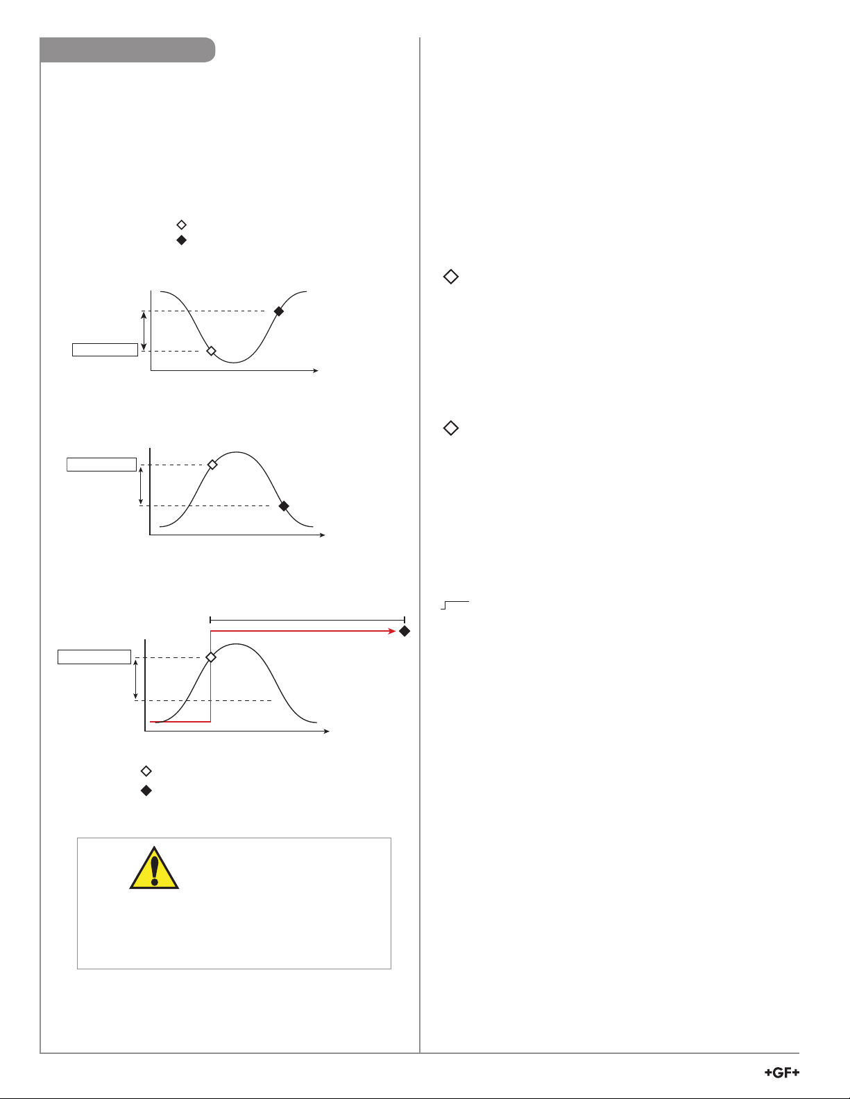
Hysteresis
Time
Low Setpoint
Process
Low Setpoint + Hysteresis
Hysteresis
Time
High Setpoint
Process
High Setpoint - Hysteresis
Relay energized
Relay de-energized
Relay Modes
The 9950 relays are selectable and confi gurable and can be
used as switches that respond when the process value moves
above or below a user-defi ned setpoint or it can be used to
generate a pulse at a rate proportional to the process value.
They can be used for Low Alarm, High Alarm or Proportional
Pulse triggering related to the process value. All relay
functions are set up in the RELAY menus.
Generation II, or greater, supports the ability to activate the
Red Backlight when a relay is activated. An optional check
box is displayed during the programming of a relay that will
turn the Red Backlight on when the relay is activated. The
Red Backlight can be activated by any relay or relay mode.
Generation II, or greater, English, French, German, or
Spanish Languages only. The relays can have a custom
label assigned for easy of identifi cation.
Low Setpoint:
Relay is on when the measured value is less than or equal
to the setpoint. Relay turns off when the measured value is
equal to or greater than the Low Setpoint + Hysteresis.
High Setpoint:
Relay is on when the measured value is greater than or equal to
the setpoint. The relay turns off when the measured value is less
than or equal to the High Setpoint - Hysteresis.
High Setpoint
16
Cycle Time
Process
Hysteresis
Relay energized
Relay de-energized
CAUTION!
If power is lost to the 9950 Transmitter during a
cycle, the Cycle Time will reset. If the condition
still exists after power is restored, the relay will be
energized for the complete Cycle Time.
9950 Transmitter
Time
Cycle High/Low:
The relay will energize for a set length of time after the
process value goes above (or below) the setpoint.
The relay will stay on for the CYCLE TIME and then turn off,
even if the process value is still above (or below) the setpoint.
The cycle will not repeat until the cycle time completes and
either the process value goes below the set point minus the
hysteresis for Cycle High or goes above the setpoint plus the
hysteresis for Cycle Low.
In FLOW, Cycle High activates the relay each time the volume
reaches the SET VOLUME setpoint (see page 23).
NOTE: To reset the timer (or volume in Flow): in the RELAY
menu, select TEST RELAY function. The timer will reset to 0
if the condition no longer exists when the TEST is performed.
The timer will restart if the condition still exists.
Page 17
Time
High Limit
Hysteresis
Low Limit
Process
Window
10
5
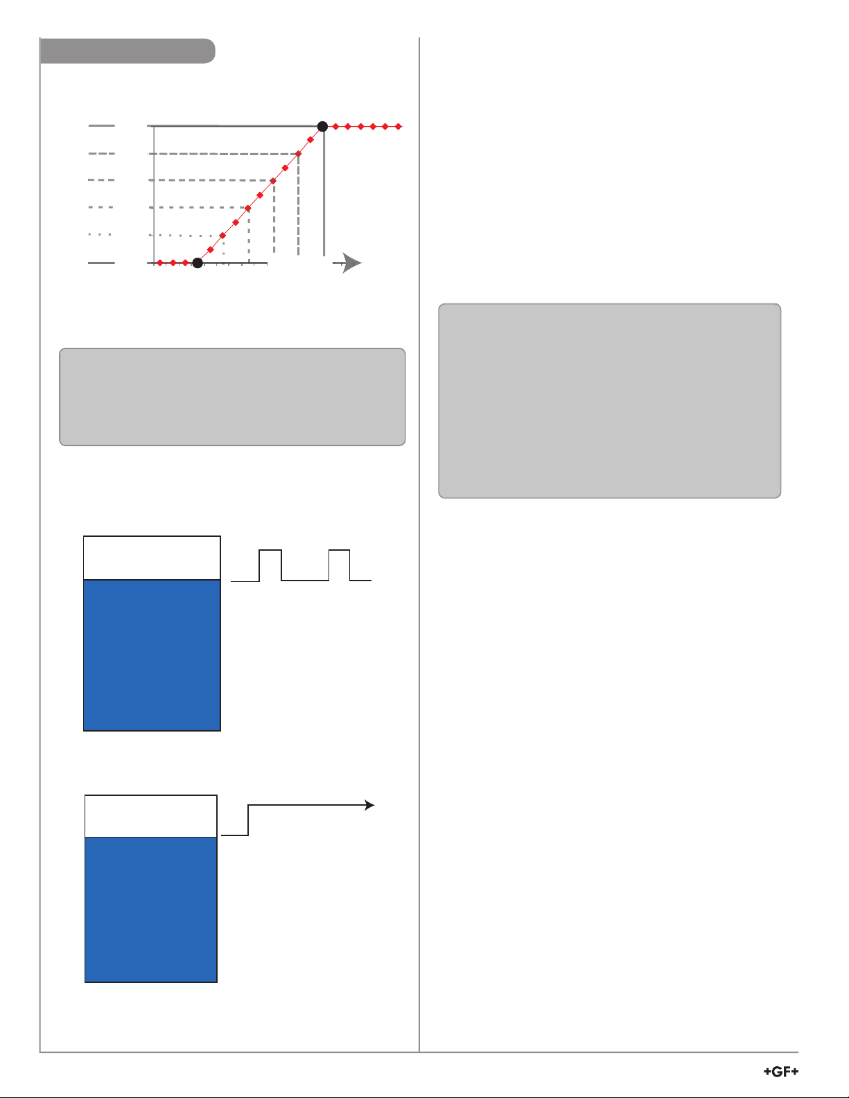
Relay Output Rate:
0 to 100 Pulses/min.
Pulse rate
0 pulses
100 pulses
7.5
Relay energized
Relay de-energized
Time
High Limit
Hysteresis
Low Limit
Process
Window
Hysteresis
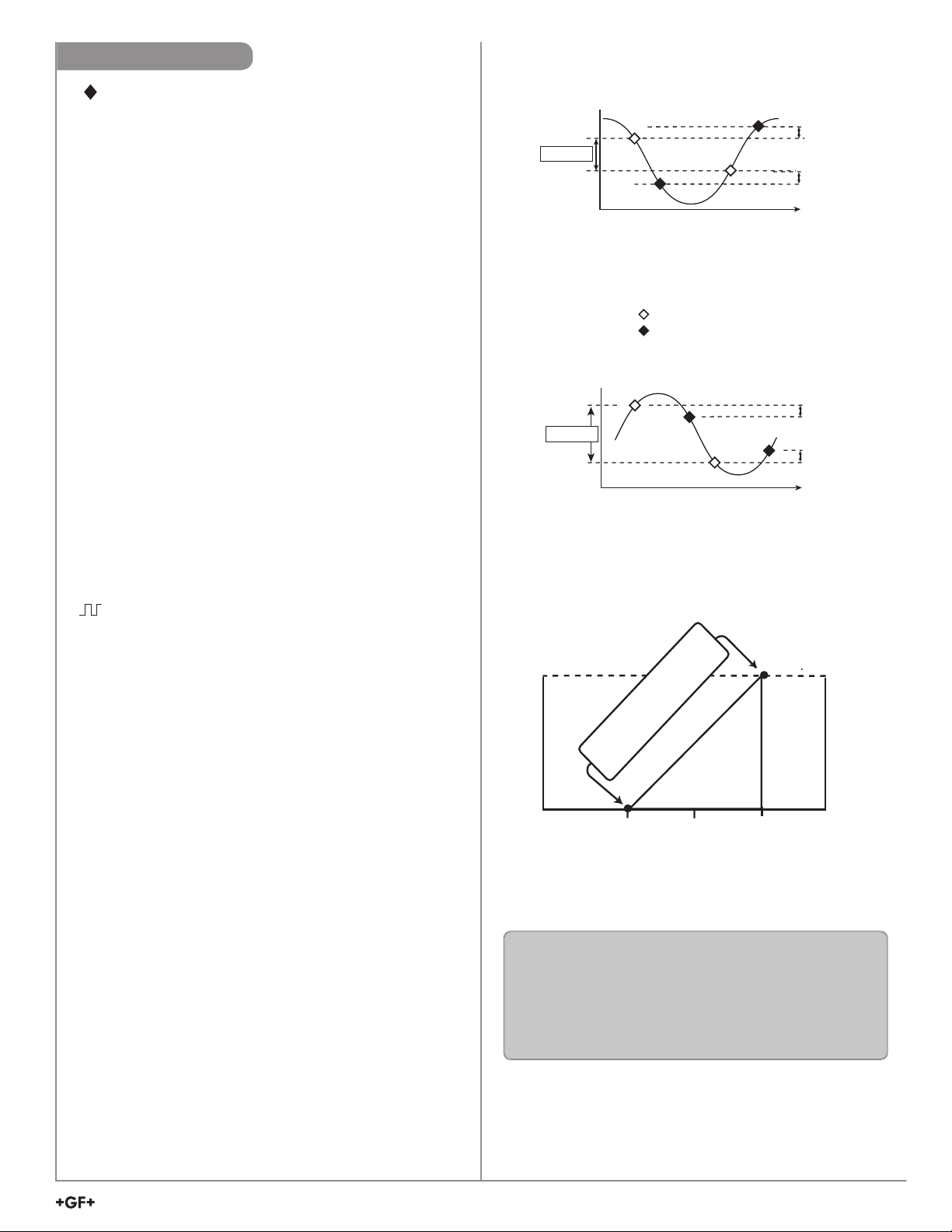
Relay Modes
Window In/Out:
Relay is on when the value is equal to or higher or lower than
the high or low setpoint.
WINDow IN = relay on if measurement is inside the window
of two setpoints.
WINDow OUT = relay on if measurement is outside the
window of two setpoints.
Window IN example
Proportional Pulse Operation:
The transmitter can output a pulse at the rate defi ned by the
settings in the CAL menu and the sensor input. The maximum
pulse output is 300 pulses per minute.
Example usage would be to control solenoid-operated
dosing pumps.
For example: As the process value rises above the setpoint,
the output will start pulsing in relation to the process value,
the maximum pulse endpoint and the programmed
pulses/minute. The pulse rate will change as the process
value changes and approaches the programmed endpoint.
This functionality can be used to precisely control the process.
The starting point, endpoint and maximum pulse rate are
select able in the RELAY menus.
NOTE: Relay LEDs will fl ash in PULSE mode.
Window OUT example
100 pulses
Starting point Endpoint
In the example:
• The output will be 0 pulses/min. when value is less
than 5.
• The output will be 50 pulses/min. when value is 7.5.
• The output will be 100 pulses/min. when value is 10
or greater.
9950 Transmitter
17
Page 18
y
Relay Modes
PWM
Maximum
100%
80%
60%
40%
Relay Pulse Width
20%
(as a % of Relay period)
0%
alwa
Relay is
s OFF
PWM
Minimum
Process value
Range
Note:
• The pulse width will be 100% of the relay period
(relay always ON) when the process value is
greater than the maximum range.
Relay is
always ON
• Pulse Width Modulation
PWM automatically varies the ratio of ON time to OFF time
proportional to minimum and maximum range settings.
The relay period is the sum of the time a relay is ON and the
time it is OFF.
Relay pulse width is the time the relay is ON.
The 9950 must be programmed with the relay period, and with
the low and high setpoints.
NOTE: The PWM mode is not used for Pressure applications.
NOTE: Relay LEDs will fl ash in PWM mode.
Example:
• The pulse width will be 0% of the relay period
(relay always OFF) when the process value is
less than the minimum range.
• The pulse width will be 100% of the relay period
(relay always ON) when the process value is
greater than the maximum range.
• The pulse width will be 60% of the relay period when
the process value is at 60% of the span between the
minimum and maximum range.
• Volumetric Pulse
The relay will activate for the set pulse width once the specifi c
volume of fl uid is registered. Flow Inputs only.
NOTE: Relay LEDs will turn on when the relay is active
• Totalizer Volume
Relay activates and latches when a specifi ed volume of fl uid is
registered on the resettable totalizer. For Flow inputs only.
Total Volume mode counts the TOTALIZER Units until the
setpoint volume is reached, then turns on the relay until the
resettable totalizer is reset.
If the Resettable Totalizer reading is greater than the setpoint,
the relay will be turned on immediately. The relay will be off
when the totalizer is below the set point or the resettable
totalizer is reset to zero.
This mode is useful to trigger a reminder when a process is
due, as for a backwash cycle or fi lter change.
18
9950 Transmitter
Page 19
Relay Modes
• Multiple
When a Relay Source is set to "MULTIPLE," the mode presents four Boolean logic formulae called "Relay Operators." Each
Operator can be programmed with up to three different conditions. The relay will only be activated when the complete formula
is satisfi ed.
Boolean Relay Logic Operations
RELAY 1
MODE
FLO(A | B | C)NITS
(A l B l C) means
"Activate this relay when
any condition (A, B, or C)
is true."
Example: Set Relay 1 Mode to A | B | C. "This relay will activate IF channel 1 pH falls below 6, OR if channel 2 pH rises above
7.8, OR if binary input 1 is active (On or Closed). Relay #1 will activate 30 seconds after any one the conditions are met".
Condition A: The pH on Channel 1 is less than 6
Condition B: The pH on Channel 2 is greater than 7.8
Condition C: Binary Input 1 is On
On Delay: 30
When operating properly, all three of these conditions are FALSE. If any one of them becomes TRUE, then Relay 1 will be
activated.
Relay 1 will remain activated until the TRUE condition becomes FALSE again, including the hysteresis band.
• Binary
When the relay source is set to “Binary." The Binary Inputs
can sense if the input is ON (Closed) or OFF (Open). The
four binary inputs only control relay activation and are not
considered a measurement source. Each binary mode is
independent and each of them can be assigned to a relay
mode.
(A & B & C) means
"Activate this relay only
when all conditions (A, B,
and C) are true."
RELAY 1
MODE
A & B & C
(A l (B & C) ) means
"Activate this relay if A is
true OR if B AND C are
both true."
RELAY 1
MODE
A | (B & C)
(A & (B l C) ) means
"Activate this relay only if A
is true AND either B or C are
also true."
Example:
A 2282 Guided Float Switch is mounted in a tank. The output of
the Float Switch will prevent a relay from activation if the tank is
below the position of the Float Switch.
RELAY 1
MODE
A & (B | C)
• Timer
When the “Timer” relay source is selected, the time can be
selected using Period or Weekday modes. Both relay modes
work directly with the time settings and formats that are entered
at start up or adjusted in the options menu. The relay is normally
open until the specifi ed time is reached, at which time the relay
is closed, triggering the relay for a specifi ed duration. The "Hold
while" feature allows the user to hold the current loop output(s)
at the present value and deactivate relays that are associated
with the measurement channel(s) for the specifi ed recovery time.
• Period Mode lets the user set a periodic interval, in days,
hours or minutes, at which the relay will activate. A First
Start screen lets the user set the day and time for the Period
Mode to begin.
• Weekday Mode lets the user specifi c the days of the week,
Sunday, Monday, Tuesday, Wednesday, etc., at which the
relay will activate. A Start Time screen lets the user set the
time of day for the weekday activation. Weekday Mode does
not have a Start Delay parameter.
Caution:
If HOLD WHILE RELAY # ACTIVE setting is changed while an Activation or Recovery is in process, the
setting will be applied after the cycle is complete. To apply the change immediately, cycle power to the 9950.
Recovery
Activation
Time
Duration
Hold measurement
during activation
and recovery
Recovery
Activation
Time
Duration
Sun
Hold measurement
during activation
and recovery
Relay Period Mode
Period 1 Period 2
Activation
Recovery
Duration
Time
and recovery
Period 2
Recovery
Time
and recovery
^
^
^
Period 1
^
Hold measurement
during activation
Relay Weekday Mode
Sunday, Tuesday and Thursday activation
Activation
Duration
Mon Tue Wed Thu Fri
Hold measurement
during activation
Activation
Duration
Activation
Duration
...
Time
...
Time
9950 Transmitter
19
Page 20
RO Membrane
RO Membrane
RO Membrane
Feed
Concentrate
Permeate
RO Membrane
RO Membrane
RO Membrane
Feed
Concentrate
Permeate
RO Membrane
RO Membrane
RO Membrane
Feed
Concentrate
Permeate
Feed
Concentrate
RO Membrane
RO Membrane
RO Membrane
Permeate
Derived Functions
When two of the same type of measurement (either primary or secondary) are present, the 9950 can calculate several derived functions
from like pairs of measurements.
Up to four derived Functions can be defi ned and used as the source for display and output functions.
• Flow, Temperature, Pressure, Conductivity and Level measurements must have matching units.
(Flow channels must also have same time base).
• Conductivity channels will automatically scale to S/cm before the function calculation is made.
• Three types of derived measurements can be applied to any set of sensors, regardless of type.
• Ratio: Measurement 1 ÷ Measurement 2 or Measurement 2 ÷ Measurement 1
• Delta (Difference): Measurement 1 - Measurement 2 or Measurement 2 - Measurement 1
• Sum: Measurement 1 + Measurement 2
• Custom labels can be assigned to Derived Functions for ease of identifi cation.
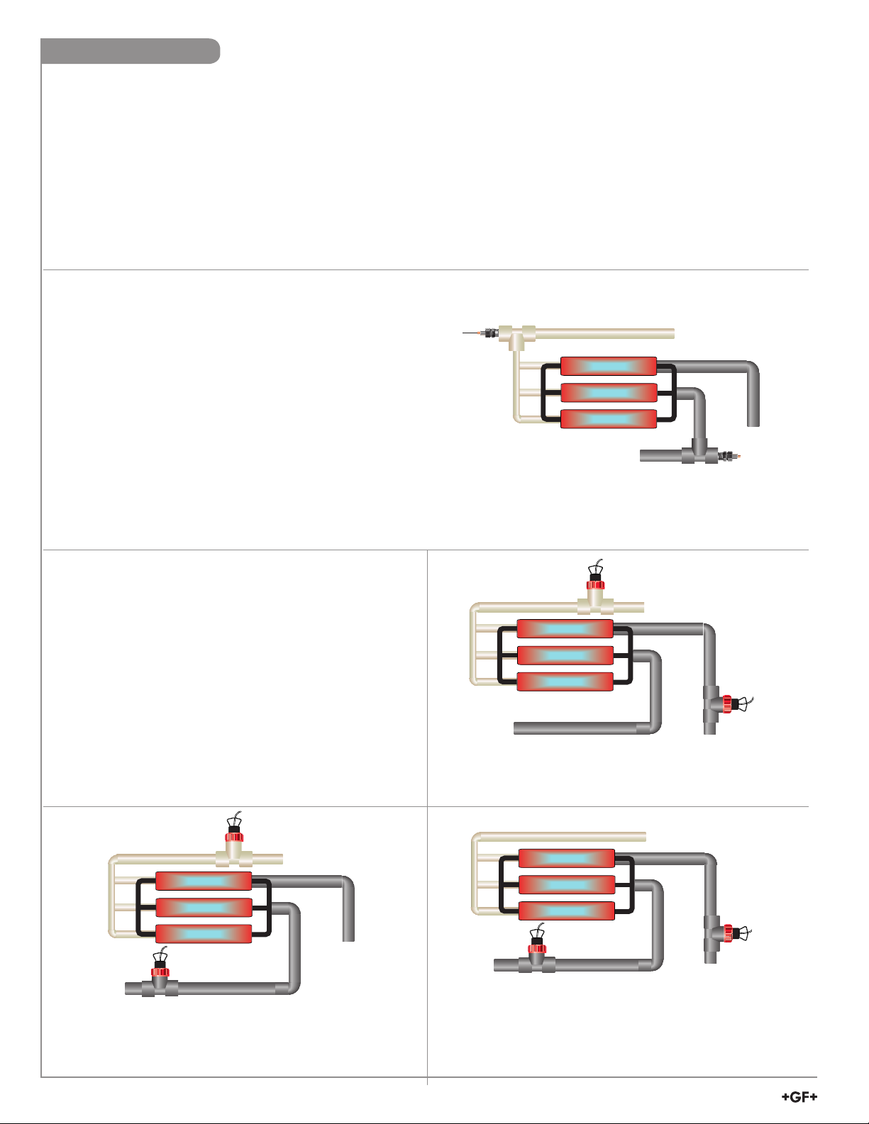
% Passage and % Reject
• % Passage and % Reject are derived functions based on
conductivity measurements only, specifi cally for use in reverse
osmosis systems.
• % Passage is the amount of contaminates remaining in the
product water compared to the level of contaminates in the feed
water. For example, if the feed water measures 375 S and the
product water measures 18.75 S, the % Passage is
(18.75/375) x 100= 5%
• % Reject is the amount of contaminates rejected to the
concentrate water compared to the amount of contaminates
in the feed water. For example, if the feed water measures
375 uS and the product water measures 18.75 uS the % reject is
[1-(18.75/375)] x 100 = 95%
• Decreasing Reject values and increasing Passage values
usually indicate a problem with the RO membrane.
% Passage: (Permeate ÷ Feed) x 100
% Reject: [1 - (Permeate ÷ Feed)] x 100
% Recovery
• % Recovery is a derived function based on fl ow rate, in a
reverse osmosis system.
• To measure % Recovery, the 9950 must have two fl ow
sensors connected. They may be located in the Feed line,
the Concentrate line or the Permeate line.
• The 9950 provides 3 different methods for calculating
Recovery to accommodate any confi guration.
• Both fl ow sensors must use the same time base and units
of measure.
% Recovery A: (Permeate ÷ Feed) x 100
In the Setup menu, select the option that states % Recovery A,
FEED: PERMEATE
20
9950 Transmitter
% Recovery B: Permeate ÷ (Permeate + Concentrate) x 100
In the Setup menu, select the option that states % Recovery B,
PERMEATE: CONC
% Recovery C: [(Feed - Concentrate) ÷ Feed] x 100
In the Setup menu, select the option that states % Recovery C,
FEED: CONC
Page 21
Menu System
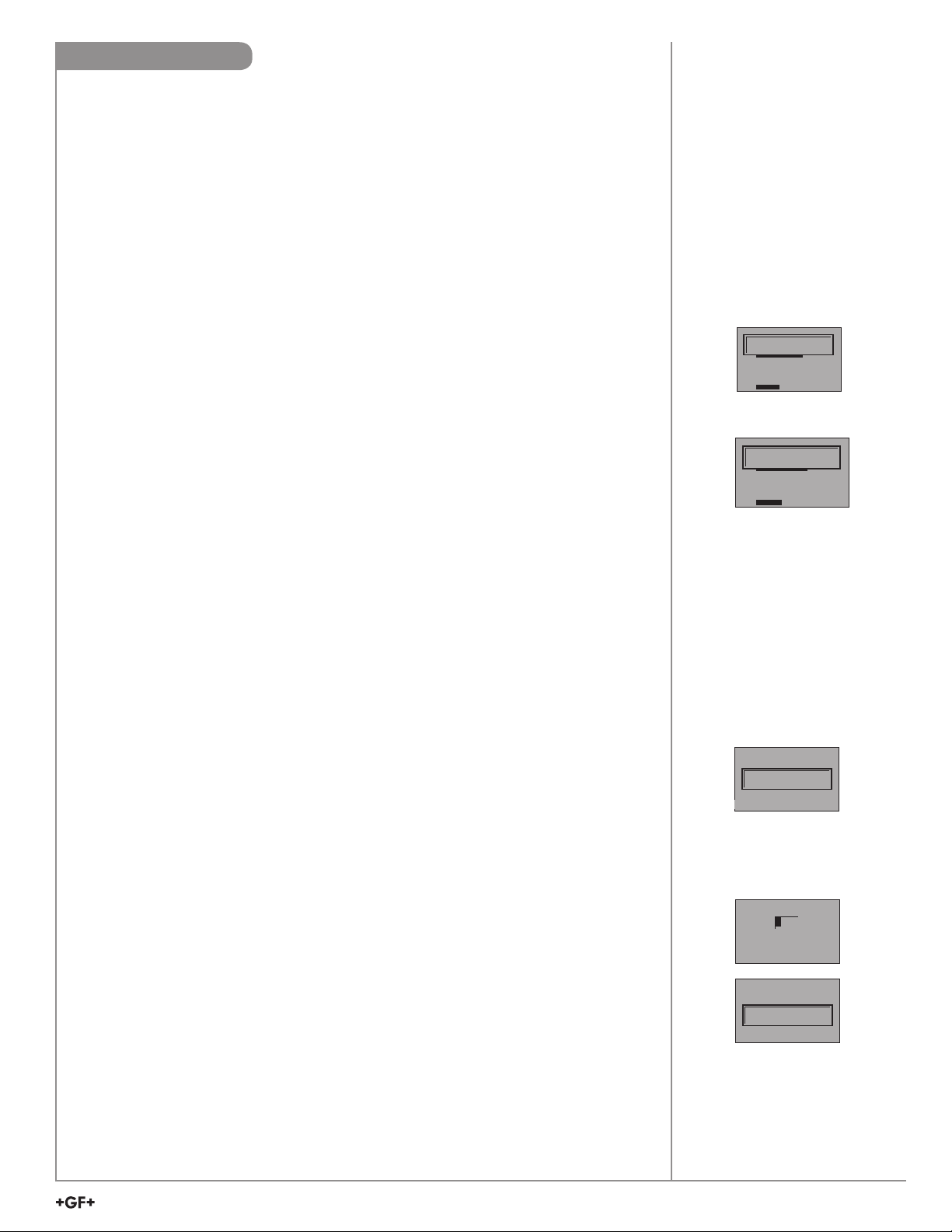
VIEW Mode Overview
The top level of screens are referred to as the VIEW Mode. This view displays measurement
values as well as current outputs, derived function values, and relay status. The horizontal bar
graph represents the primary measurement value that is also displayed in the numeric fi eld
above the bar graph. The bar graph is primarily used to display the full scale range of
the sensor, but can be scaled via the OPTION menu item.
During normal operation, the 9950 displays the VIEW mode.
• To select a display, press the or arrow keys.
The display selections scroll in a continuous loop.
• Changing the display selection does not interrupt system operations.
• No password is necessary to change display selection.
• Output settings cannot be edited from the View Mode.
• The display will return to the VIEW mode if no button is pressed for 10 minutes.
MENU Mode Overview
The MENU mode enables the user to view and confi gure all menu items.
The fi ve menus available are: CAL, INPUT, LOOP, RELAY, and OPTION.
Error Handling
Errors occurring while on the
measurement screens show a
specifi c message (e.g., Wrong
Sensor). This message will
fl ash and stays on for 3 seconds
and fl ash off. Once the error is
resolved or cleared, the error
message stops.
_ _ _ _ ._
CH1
MISSING SENSOR
9999.9
00.0 0
CH2
6 2 .8
00.0 0
7 .0
mV
GPMS
00.00
15.00
pH
°F
MENU Mode is entered by pressing and holding ENTER for three seconds.
To select a menu use the and arrow keys to highlight the desired menu and press ENTER
to select the menu.
In the selected menu, use the and keys to navigate through the menu.
Use the , and keys to edit the selected item
(see Menu Navigation discussion, page 22).
To save the new selection, press the ENTER key. A message displaying “Saving” will be
displayed for 3 seconds. After this message is displayed, the newly selected value will be
displayed, if applicable. To abandon the changes press the and arrows simultaneously.
Password Overview
The password is often required to start editing. Once entered correctly, this password will not
be needed for subsequent edits, until the menu system is exited.
The password is required when the menu system is re-entered.
Your choice of password (STD or CODE) is selected in the Options Menu.
• STD
The standard (STD) password is , pressed in sequence. This password is
designed to protect the 9950 from unintentional changes. It is best suited for systems
where a group of people need to be able to change settings.
• CODE
The CODE default setting is 0000, adjustable to any 4-digit numerical code up to 9999.
Using a personal code provides the maximum degree of security.
This code can be modifi ed in the Options menu.
Password Reset
Turn off 9950. Press and hold all 4 keys on keypad while turning on 9950 and unit
will revert back to STD password.
_ _ _ _ ._
CH1
WRONG SENSOR
9999.9
00.00
CH2
6 2 .8
00.00
7.0
mV
GPMS
00.00
pH
15.00
°F
Scrolling
In some cases, more than one
message or measurement may
need to be displayed. This is
accomplished by alternating the
message portions across the
screen.
PASSWORD TYPE
WRONG CODE
TEXT 3
In the MENU mode, if the
wrong code or password is
entered, an ERROR message
is displayed.
LANGUAGE
0
0000
LANGUAGE
ENTER CODE
LANGUAGE
PASSWORD
SAVING
TEXT 3
To change your CODE, go
to OPTIONS mode, enter
your desired code and press
ENTER. (The STD password
cannot be changed).
9950 Transmitter
21
Page 22
Common Menus
Common Menus
The menu system shares certain modes between sensor
types.
The following describes the menus found in common between
most sensor types.
INPUT Menu
NOTE:
Menu and Mode displays shown are examples only.
Your displays may vary.
CAL
INPUT
INPUT
LOOP
RELAY
OPTION
LOOP Menu
LOOP 1
SOURCE
CH SECONDARY
LOOP 1
LABEL
LOOP 1
LOOP 1
MODE
LOG
L1 4 mA SETPOINT
4
(ALL) Manually select Sensor Type (See page 9 for further instruction).
Allows user to reset 9950 Transmitter to Factory settings. Allows user to confi gure sensor
ENTER
specifi c parameters.
Note: User is strongly discouraged from changing the sensor type away from the correct sensor.
ENTER
The following can individually be set for each loop on the 9950. Loops 1 and 2 are in the 9950 base unit.
Loops MOD1 A and MOD1 B are present when a loop module is in the Module 1 Slot. Loops MOD2 A and
MOD2 B are present when a loop module is in the Module 2 Slot.
Select source for each loop. Choose CH 1 PRIMARY, CH 1 SECONDARY, CH 2 PRIMARY, CH 2 SECONDARY,
or DERIVED FUNCTION 1 - 4. Secondary Values are only available for pH, Conductivity/Resistivity, Level, Salinity,
and Dissolved Oxygen. Derived Functions are only available for confi gured Derived Functions.
English, French, German, and Spanish languages only. A custom label can be assigned to the loop for ease of
identifi cation.
(COND/RES only) Select LIN/LOG. Default = LIN
See LOG Current LOOP Output discussion in Appendix.
0.00
UNITS
L1 20 mA SETPOINT
100.00
UNITS
LOOP 1
ERROR VALUE
22 mA
L1 ADJUST 4 mA
4.00
mA
L1 ADJUST 20 mA
21.0
mA
L1 TEST LOOP
12.05
mA
(ALL) Set value corresponding to desired 4 mA output. 6 digits max. Default = 0 (ORP = -999).
(ALL) (Not shown in COND/RES LOG Mode)
Set value corresponding to desired 20 mA output. 6 digits max.
Defaults = 100 (Flow, Cond/Res, Temp), 14 (pH), 1000 (ORP), 10 (Lvl/Prs), 5 (4 to 20 mA), 80 (Sal).
(ALL) Set desired LOOP output value when sensor error (e.g., bad sensor, broken wire) is detected.
Select (3.6 mA, 22 mA,
or NONE). Default = 22
(ALL) Allows fi ne-tuning to compensate for errors in other equipment connected to the 9950.
Adjust the current output at 4 mA. The display value represents the precise current output.
Adjustment limits: from
3.80 mA minimum to 5.00 mA maximum. Default = 4.00 mA
(ALL) Allows fi ne-tuning to compensate for errors in other equipment connected to the 9900. Adjust the current
output at 20 mA. The display value represents the precise current output. Adjustment limits: from 19.00 mA
minimum to 21.00 mA maximum. Default = 20 mA.
(ALL) Press or to manually control the output current value from 3.8 mA to 21.00 mA to test the output of
LOOP. The current loop will revert to automatic control when this menu item is left.
22
9950 Transmitter
Page 23

Common Menus
RELAY Menu
RELAY 1
SOURCE
CH 1 PRIMARY
RELAY 1
MODE
BINARY ON
RELAY 1
SOURCE
TIMER
RELAY 1
04/23/2016
mSSTART DATETA
RELAY 4
SUN
MON
9
9
WED
THU
9
9
SAT
9
RELAY 1
SOURCE
MULTIPLE
All relays select source for each Relay 1 - 4.
Choose CH 1 PRIMARY, CH 1 SECONDARY, CH 2 PRIMARY,
CH 2 SECONDARY, BINARY 1 - 4, DERIVED FUNCTION 1 - 4, TIMER, or MULTIPLE. Secondary Values are
only available for pH, Conductivity/Resistivity, Level, Salinity and Dissolved Oxygen. Derived Functions are only
available for confi gured Derived Functions.
(All Binary) Binary Inputs can be set to active when On (Closed) or Off (Open).
Requires the 3-9950.393-3 module for use.
(TIMER) Allows the user to select either Period or Weekday Modes.
TIMER in PERIOD mode will allow the user to select a unit of time, a quantity of time, a specifi c start date, a
specifi c start time, a duration, and a HOLD feature.
Default = HOURS, 2, 12/01/2015, 10:00, 60 secs, HOLD WHILE RELAY # ACTIVE NO
TIMER in WEEKDAY mode will allow the user to select a day or multiple days of the week with a START TIME,
TUE
9
FRI
9
DURATION, and a HOLD feature.
Default = 10:00, 60 secs, HOLD WHILE RELAY # ACTIVE NO
MULTIPLE will use up to 3 sources where the relay will only be activated if these sources meet specifi ed
conditions A|B|C, A&B&C, A|(B&C), A&(B|C) Default = OFF (Refer to pg 19.)
RELAY 1
MODE
A | B | C
RELAY 1
MODE
A & B & C
RELAY 1
MODE
CA | (B & C)T
RELAY 1
MODE
A & (B | C)
RELAY 1
MODE
OFF
RELAY 1
LABEL
RELAY 1
R1 SET LOW
0.00
mUNITSA
MULTIPLE MODE A|B|C will activate if any condition A, B, or C is true.
MULTIPLE MODE A & B & C will activate if all conditions A, B, and C are true.
MULTIPLE MODE A (B & C) will activate if A is true or if B and C are true.
MULTIPLE MODE A (B | C) will activate if A is true and if B or C are true.
(ALL) Select the desired mode of operation for the (R1) output (OFF, LOW, HIGH, WINDow IN, WINDow OUT,
CYC LOW (except FLOW), CYC HIGH, PROP PuLSe, VOL PuLSe, PWM, TOTAL, USP, ERROR mode) (See
page 15, Relay Modes). Default = OFF. Continue stepping through to select R2, R3 and R4 output modes. When
MODE is set to ERROR, relay energizes if sensor problem is detected on either channel. ON DELAY delays the
energizing of the relay until after the programmed delay time. (See Cycle High/Low discussion on page 16).
English, French, German, and Spanish only.
A custom label can be assigned to the relay for ease of identifi cation.
(ALL) (Shown if LOW, WIND IN/OUT or CYC LOW mode)
Relay turns on if process measurement is equal to or lower than this value. Set desired value.
9950 Transmitter
23
Page 24

Common Menus
RELAY Menu
R1 SET HIGH
100.0
mUNITSA
R1 SET VOLUME
100.00
mUNITSA
R1 HYSTERSIS
0.50
0UNITS
R1 USP PERCENT
0.20
%
R1 ON DELAY
5.0
SEC
R1 PULSE MIN
0.00
MULTUNITSIPLE
R1 PULSE MAX
100.00
OFUNITSF
R1 MAX RATE
120.00
mPULSES/MINA
R1 PWM MIN
00.0
mUNITSAA
R1 PWM MAX
10.00
mUNITSA
R1 PWM PERIOD
1.00
SEC
R1 CYCLE TIME
0.00
%SECE
(ALL) (Shown if HIGH, CYCLE HIGH (all except Flow) or WIND IN/OUT mode)
Relay energizes if process measurement is equal to or higher than this value. Set desired value.
(FLOW only) (Shown if Cycle High (Flow), TOTAL or VOL PLS mode)
Amount of accumulated fl ow that must be counted before a pulse is sent out.
Relay energizes if fl ow volume exceeds this value. Set desired value.
(ALL) (Shown if LOW, HIGH, WIND IN/OUT, CYC LOW/HIGH or USP mode)
Hysteresis prevents the system from chattering around the set point.
Set amount (in units of measure from INPUT Mode) to add to SET LOW or SET HIGH values.
(COND/RES only) (Shown only in USP mode)
Relay energizes if USP value drifts by this value away from USP limit.
(See USP Limits discussion in the appendix, page 66). NOTE: Relay will activate if USP limit is exceeded,
Temperature Comp is set to Linear or Pure Water, Conductivity Measurement is NOT in uS, or if the Conductivity
is reporting a measurement error.
(ALL) (Shown if Low, High, WIND IN/OUT, CYC LOW/HIGH or Error mode)
Set seconds (up to 9999.9) to wait before activating relay once the relay condition is true.
(ALL except PRESSURE) (Shown only if PROP PLS mode)
Set minimum setpoint value for proportional pulsing.
(ALL except PRESSURE) (Shown only if PROP PLS mode)
Set maximum setpoint value for proportional pulsing.
(ALL except PRESSURE) (Shown only if PROP PLS mode)
Set desired maximum pulse rate (300 max)
NOTE: Pulse width fi xed at 100 ms.
(ALL except PRESSURE and FLOW) (Shown only if PWM mode)
Set minimum value for pulse width modulation.
(ALL except PRESSURE and FLOW) (Shown only if PWM mode)
Set maximum value for pulse width modulation.
(ALL except PRESSURE and FLOW) (Shown only if PWM mode)
Set time value for one complete pulse cycle (relay ON time + relay OFF time).
(ALL) (Shown only if CYC LOW/HIGH mode)
Set time in seconds (up to 99999) for relay to remain on. (See discussion on page 16)
24
9950 Transmitter
Page 25

Common Menus
RELAY Menu
R1 PULSE WIDTH
1.00
SEC
R1 SET TOTAL
100.00
SEUNITSC
RELAY 1 ACTIVATE
RED BACKLIGHT
NO
RELAY 1
TEST RELAY
mA
OPTION Menu
ENGLISH
FRANÇ
DEUTCH
ESPAÑOL
中文
TIME FORMAT
24 HR
(FLOW only) (Shown only if VOL PULS mode) Set time value for one pulse width.
(FLOW only) (Shown only if TOTAL) Resettable value that, when exceeded, turns relay on.
Must reset Totalizer (in VIEW Mode) to clear relay. Set maximum value.
Select Yes to have the Red Backlight illuminate during relay activation, No to not have the Red Backlight
activated by the relay activation.
(ALL) Press or to turn relay on or off for testing purposes.
Can also be used to reset or latch/unlatch the relay. Does NOT reset the Totalizer.
Choose desired the language for the 9950. Default = English
Choose a time format between a 24 Hour or an AM/PM clock. Default = 24 HR
BINARY ON
SET TIME
08:56
TIMER
DATE FORMAT
MM/DD/YYYY
MULTIPLE
SET DATE
02/25/2016
OFF
SET DECIMAL MARK
999.99
mA
SELECT UNITS
METRIC
mA
Set the time according to the format chosen 00:00
Date Format; MM/DD/YYYY, DD/MM/YYYY, YYYY/MM/DD
Set the date according to the format chosen 00/00/0000
Choose either comma or point according to local practices. Default = 999.99 (point).
Choose METRIC or US CUSTOMARY
NOTE: Defaults for most relay functions are dependent upon sensor type and are not listed here.
9950 Transmitter
25
Page 26

Common Menus
OPTION Menu
WHITE BACKLIGHT
AUTO LOW
mA
RED BACKLIGHT
ON
DISPLAY
BAR GRAPH
ON
CH2 BAR GRAPH MIN
0.00
GPM
CH2 BAR GRAPH MAX
100.00
GPM
FUNCTION 1
NONE
OFF
CH1
_ _ _ _._
GPM DECIMAL
CH1
_ _ _ _._
°F DECIMAL
CH1
_ _ _ _._
TOTAL DECIMAL
CH1
TOTAL LOCK
OFF
COND/RES
AUTORANGE
OFF
PASSWORD TYPE
STD
%
PASSWORD TYPE
CODE
%
White Backlight; Off, Low, High, Auto Low, Auto High
The Red Backlight illuminates when an error condition is detected or user selected relay(s) are activated.
Default = ON
Display Bar Graph; On, Off
Enter a value to represent bar at minimum.
Default = 0 (ORP = -999)
Enter a value to represent bar at maximum.
Defaults = 100 (Flow, Cond/Res, Temp), 14 (pH), 1000 (ORP), 10 (Lvl/Prs), 5 (4 to 20 mA),
80 (Sal), 20 (DO)
Function 1 - 4, Confi gure the derived function, up to four functions available.
(Refer to page 20 for further detail)
(ALL) Set the decimal to the best resolution for your application for both CH1 and or CH2.
The display will automatically scale up to this resolution for each channel.
Select 0, 1, 2, 3, or 4 decimal places, (varies by parameter).
Default = 1 Decimal Place
(pH, COND/RES, TEMP, SAL, DO only)
Set the Temperature decimal to the best resolution for your application for both CH1 and or CH 2.
The display will automatically scale up to this resolution. Select 0, 1, or 2.
Default = 1 Decimal Place
(FLOW only) Set the decimal to the best resolution for the Permanent and Resettable 2 Totalizer display.
The display will automatically scale up to this resolution. Select 0, 1, 2, 3, or 4 decimal places.
Default = 1 Decimal Place
(FLOW only) requires password to reset the resettable totalizer. Select OFF, ON (Does not affect Permanent
Totalizer).
Default = OFF
(CONDUCTIVITY/RESISTIVITY only) Set ON to automatically scale the conductivity/resistivity within range to
be displayed.
Default = OFF
(ALL) Select STD, CODE.
Default = STD (Refer to page 21 for further detail)
(CODE) If code is selected
Default Code = 0000 (Refer to page 21 for further detail)
26
9950 Transmitter
Page 27

Common Menus
OPTION Menu
MEMO
MEMO
SEC
MODBUS
MODULE
NONE
MODBUS
COMMUNICATION
SETTINGS ->
MODBUS
REMOTE UPDATE
NO
9950
(ALL) Enter 17-character string, if desired.
Default = MEMO
Select the location of the Modbus Module, None (Default), Module 1, or Module 2
Important: You must select the location of the Modbus Module for proper operation.
Press the Right Arrow key to change the settings of the Modbus Module
See page 67 for Modbus Communication Settings Menus
Setting Modbus Remote update to Yes allows remote Modbus device to change the settings on the 9950.
Setting Modbus Remote Update to No prevents remote devices from make any changes to the 9950. Remote
device will still be able to read all of the Modbus parameters.
GENERATION 3
SEC
USER MANUAL
100.00
SEC
VIEW Mode
50.30
CH1
40560.0
0.00
CH2
987.9
65.5
0.00
50.30
0.00
987.9
0.00
CH1
50.30
FLOW
0.00
CH2
987.9
FLOW
0.00
Func 1
Func 2
Func 3
Func 4
CH 1 TOTALIZER
P 40560.0
R 40560.0 ->
LITERS
INTERNAL LOOPS
LOOP 1
LOOP 2
GPM
100.00
GPM
100.00
GPM
100.00
GPM
100.00
GPM
100.00
GPM
100.00
50.00
100.00
2.00
0.00
12.00
4.00
Displays Transmitter Generation Version.
QR code for user manual.
Measurement View Mode Screens are depicted in the Sensor Specifi c Menus. Below are the screens
that all parameters share in common.
R
View Measurement 1 displays the primary value with the secondary value below. This is the normal display and
does not time out.
R
View Measurement 2 displays the primary value in large type. This screen does not time out.
View Measurement 3 displays the primary value and the channel name. This screen does not time out.
Function values are stated to the right of the function number. Select a derived measurement function,
up to four functions available. (SUM, DIFFERENCE, RATIO, % PASSAGE, % REJECT, % RECOVERY A,
% RECOVERY B, % RECOVERY C) (See pg. 19 for further details)
Parameter specifi c screen.
Flow totalizer, pH raw mV, ORP, pH Impedance, pH/ORP Sensor Data, raw mV, 4 - 20 mA input, conductivity,
DO cap expiration date.
Displays the internal 4 to 20 mA LOOP output for each channel assigned primary and secondary sources.
(3.6, 22.00 are error output values).
MODULE LOOPS
MOD1 A
MOD1 B
MOD2 A
MOD2 B
18.00
12.00
8.00
4.00
Displays the Module 4 to 20 mA LOOP output for each channel assigned primary and secondary sources.
(3.6, 22.00 are error output values).
9950 Transmitter
27
Page 28

Common Menus
VIEW Mode
RELAY STATUS
RELAY 1
RELAY 2
RELAY 3
RELAY 4
BINARY STATUS
BINARY 1
BINARY 2
BINARY 3
BINARY 4
MODBUS STATUS
ADDRESS
BUS MSG CNT
9950 MSG CNT
MSG ERR CNT
SYS CONFIG
CH1
CH2
RELAY
MOD1
MOD2
GENERATION 3
SW VER
9950 S/N
TEXT 1
MENU ->
TEXT 3
12/01 10:00
SUN 10:00
OFF
OFF
OFF
999
99999
99999
99999
FLOW
FLOW
399504033
4-20 OUT
30-13
0123456789
ON
ON
Relay status is stated to the right of the relay number as (OFF, ON, DATE/DAY and TIME) for each relay.
ON
If Relay is using Timer Source, time and date of next activation will be displayed.
while counting down.
NOTE: (Reset the Timer) In the RELAY menu, select TEST RELAY function.
The relay(s) will remain ON
The timer will restart if the condition still exists.
Binary labels can be edited by pressing Right Arrow on the Binary Status screen and scrolling through the Binary
Label submenu. Pressing Cancel (Up and Down simultaneously) returns to the Binary Status screen in View
Mode.
English, French, German, and Spanish only. Binary status is stated to the right of the binary channel number as
(OFF, ON) for each of the four binary inputs.
The Modbus Status screen is displayed if a Modbus module is installed.
SYS CONFIG shows channel and parameter and relay module part number.
Generation Screen shows version of software and serial number of unit.
Note: Top shows the Generation of 9950
MENU-> will allow access to top level menu by pressing the key.
DATE
09/01/2016
09:06
EASYCAL
CH1 pH ->
CH2 ORP ->
DATE and TIME display show the current system date and time
pH EASYCAL looks for 4, 7, or 10 pH buffers. (See page 59)
ORP EASYCAL looks for 87, 264, or 476 mV buffers. Press the to begin EASYCAL. (See page 61)
Important
The Relay, Mod1, and Mod2 number returned by the Sys Confi g Screen is not the Mfr. Part No.
To convert from the displayed number to the GF Signet Mfr. Part No. use the chart below.
Module RELAY, MOD1, or MOD2 Mfr. Part No.
Single Channel Conductivity 399504041 399503941
Dual Channel Conductivity 399504042 399503942
Dual Channel 4 to 20 Out 39950408 399503982
Modbus Module 39950409 39950395M
Relay Four Mechanical 399504031 399503931
Relay Two SS and Two Mechanical 399504032 399503932
Relay Two Mech and Four Binary 399504033 399503933
28
9950 Transmitter
Page 29

Sensor-Specifi c Menus
Flow
The following pages list the sensor-specifi c settings for each sensor type. The user can confi gure the
unit to run each channel on different parameters if needed.
VIEW Mode Menu
CH1
50.30
40560.0
0.0 0
CH2
987.9
65.5
0.0 0
Displays the fl ow rate and the resettable
or permanent totalizer below. This is the
normal display and does not time out.
50.30
0.00
987.9
0.00
CH1
50.30
FLOW
0.00
CH2
987.9
FLOW
0.00
CH 1 TOTALIZER
P 40560.0
R 40560.0 ->
LITERS
GPM
100.00
GPM
100.00
GPM
100.00
GPM
100.00
GPM
R
100.00
GPM
R
100.00
View Measurement 2 displays primary value in large type. This screen does not time out.
View Measurement 3 displays the primary value and the channel name. This screen does not time out.
Displays the Permanent Totalizer and Resettable Totalizer for each FLOW channel (note the "P"
indicating Permanent and "R" for Resettable) Pressing will prompt you to reset. Pressing again
will verify YES or NO. Pressing ENTER will reset the totalizer.
FLOW Setup Checklist
1. Make sure FLOW sensor type is selected
(see System Setup Menu, page 9).
2. Set the Units of Measurement.
3. Set Sensor Type (Freq or S3L) and if 515 or 525, select Yes.
4. If LOOP is used, set the minimum and maximum 4 to 20 mA setpoints.
5. Set K-Factor (pulses per Unit Volume) from Flow Sensor manual.
6. Set Totalizer factor.
7. Set Last Cal Date and initials.
8. If applicable, set up relay functions for your application.
CAL Menu
CH 1 FLOW
HOLD OUTPUTS
CH 1 FLOW
CH 1 FLOW
CH 1 FLOW
RATE CAL ->
MULTIPLE
CH 1 FLOW
VOLUME CAL ->
CH1 FLOW
OFF
KF
60.00
TF
1.00
OFF
ON prevents relays from activating while making adjustments and relays in PULSE mode will suspend
pulsing. Output is held until the user exits the CAL menu or turns it off. Select ON/OFF.
Default = OFF
Set K-Factor (pulses per unit volume) from Flow Sensor manual.
Min: 0.0001, max. 9999999. Cannot be zero. Default = 60.0000
Sets the volume of each count of the Totalizer as a multiple of the volume unit of the K-Factor.
Min: 0.0001, max. 9999999. Cannot be zero. Default = 1.0000
Select to calibrate using rate method. (see Appendix, page 64)
Select to calibrate using Volume method. (see Appendix, page 64)
LAST CAL ->
12-31-2015 XX
Enter date of calibration (MM-DD-YYYY) and initials of calibrator (XX)
9950 Transmitter
29
Page 30

Flow
INPUT Menu
CHANNEL 1
NAME
FLOW
CH 1 FLOW
MODE
SENSOR FREQ
CH 1 FLOW
515/2536
YES
CH 1 FLOW
GPM
FLOW UNITS
CH 1 FLOW
CUST/S
CUSTOM UNITS
TOTALIZER
TOTAL UNITS
GALLONS
CH1 FLOW
DISPLAY
R TOTALIZER
English, French, German, and Spanish Only. If desired, a custom name can be entered.
Enter 17-character string.
Default = FLOW
If your fl ow sensor is confi gured for frequency output, select FREQ.
If confi gured for Digital (S
3
L) output (recommended), select S3L.
Default = FREQ
If your fl ow sensor is self powered such as a 515/525, select YES.
If your fl ow sensor is not self powered such as a 2536, select NO.
Default = YES
Select the unit of measure from the pull down menu. Custom units can be created and used.
The last character sets the timebase: S (seconds) M (minutes) H (hours) D (days).
Default = GPM
English, French, German, and Spanish Only. Set UNITS to CUST/S, CUST/M, CUST/H, CUST/D
allows user to set custom units for primary measurement. CUST/S, M, H, D label can be adjusted to
refl ect to user's custom units.
Identifi es the Totalizer units. It has no effect on any calculation.
Default = GALLONS
Set the Totalizer displayed in view mode. Select R TOTALIZER for resettable or select PERM
TOTALIZER for permanent.
Default = R TOTALIZER
CH1 FLOW
100.0
SENSITIVITY
CH1 FLOW
AVERAGE
OFF
CH 1 FLOW
MOTYPEDE
FLOW
The Sensitivity setting determines how the 9950 responds to sudden changes in the fl ow rate for
a frequency sensor. The value is expressed in units of measurement. If the setting is exceeded, it
"overrides" the Averaging function briefl y to allow for the actual change in fl ow rate to be displayed.
Averaging resumes shortly after. The result is a smooth fl ow display and a quick response to large
shifts in the fl ow rate. To disable the sensitivity function set it to 99999.
Dampens display, output and relay response rates.
Select Low, Med, High, OFF. (See discussion in Appendix, page 54)
Default = OFF
Current channel type is listed. Manually change channel type to match sensor type if sensor is not
found by S
3
L search.
Default = FACTORY, S3L sensors will automatically be found by transmitter. All other sensors must be
manually set.
30
9950 Transmitter
Page 31

pH
VIEW Mode Menu
CH1
7.0
77.0
-1.00
CH2
4.0
99.0
-1.00
Displays the pH value and the
temperature below. This is the normal
display and does not time out.
pH
°F
15.00
pH
°F
15.00
pH Setup Checklist
1. Make sure pH sensor type is selected.
(see System Setup Menu, page 9)
2. Set the Temperature Units (°C or °F).
3. If LOOP is used, set the minimum and maximum 4 to 20 mA setpoints.
4. Perform calibration (EasyCal, Standard or Standard and Slope).
5. Set Last Cal Date and initials.
6. Select source for Relay output (pH or Temp).
7. If applicable, set up relay functions for your application.
-1.00
-1.00
CH1
pH
-1.00
CH2
pH
-1.00
7.0
4.0
7.0
7.0
RAW
CH 1 264.10 mV
CH2 182.10 mV
GLASS IMPEDANCE
CH1 1049 MOhm ->
REF IMPEDANCE
CH1 27 MOhm ->
Sensor Data
CH1->
EASYCAL
pH
15.00
pH
15.00
pH
15.00
pH
15.00
View Measurement 2 displays primary value in large type. This screen does not time out.
View Measurement 3 displays the primary value and the channel name. This screen does not time out.
Displays the RAW millivolt input from the electrode. Use this display to determine the relative
condition of your electrode during periodic calibration.
[Glass Impedance] 2751 only, pH only, last measured glass Impedance, press [RIGHT] key to
manually update reading.
2751, 276x electrodes Only, last reference impedance measurement, press [RIGHT] key to update
reading.
2571 only. Using the right arrow key, you will see the following screens: [Serial Number] Electrode
Serial Number, [Model Number] Electrode Model Number, [pH Calibration Slope] Calibration Slope
Value, [pH Offset] Calibration Offset, [Temperature Offset] pH only, Temperature Offset Value, [Factory
Impedance] pH only, Factory pH glass Impedance, [Usage Time] Electrode Runtime in Hours,
[Minimum pH] Minimum Measured Value, [Maximum pH] Maximum Measured Value, [Minimum
Temperature] pH only, Minimum Measured Temperature, [Maximum Temperature] pH only, <Maximum
Measured Temperature.
CH1 pH ->
CH2 pH ->
pH EASYCAL looks for buffers of 4, 7, or 10 pH buffers. (Refer to page 59)
9950 Transmitter
31
Page 32

pH
CAL Menu
CH 2 pH
OFF
HOLD OUTPUTS
CH 2 pH
CAL
AT INSTRUMENT
CH 2 pH
EASYCAL ->
C ST CELL CON-
CH 2 pH
SET
TEMPERATURE ->
CH 2 pH
°SETF
pH STANDARD ->
CH2 pH
SET
pH SLOPE
ON prevents relays from activating while making adjustments and relays in PULSE mode will
suspend pulsing. 4 to 20 mA output is held until the user exits the CAL menu or turns it OFF.
Select ON/OFF. Default = OFF
Select AT SENSOR to perform calibration using the Signet 2750/2751 Sensor Electronics.
Select AT INSTRUMENT to perform calibration at the 9950 via EasyCal or manual calibration.
(See pH Calibration procedures in the Appendix, page 60).
Default = AT INSTRUMENT
(CAL AT INSTRUMENT only) Press to start the EasyCal process.
The password prompt is the same as the other parameters.
(See pH EasyCal procedure in the Appendix, page 59)
(CAL AT INSTRUMENT only) Applies a linear offset to the temperature measurement.
"SAVING" will appear if offset is acceptable, "ERR TOO LARGE TO CALIBRATE" if offset is outside of
range.
(CAL AT INSTRUMENT only) Applies an offset to the pH measurement. The slope value and the standard
value must be at least 2 pH units apart. The ideal values are the minimum and maximum values of your
process.
(See pH Calibration procedures in the Appendix, page 60). Shows error message if offset is too high.
(CAL AT INSTRUMENT only) Applies a slope to the pH measurement. The slope value and the standard
value must be at least 2 pH units apart. The ideal values are the minimum and maximum values of your
process. (See pH Calibration procedures in the Appendix, page 60). Shows error message if slope is too
low or high.
CH2 pH
SET
RESET pH CAL ->
CH2 pH
100.0
RESET TEMPCAL ->
CH 2 pH
100LAST CAL.00
12 - 31 - 2015 XX
(CAL AT INSTRUMENT only) Press to reset pH calibration to factory default.
(CAL AT INSTRUMENT only) Press to reset temperature calibration to factory default.
Enter date of calibration (MM-DD-YYYY) and initials of calibrator (XX)
32
9950 Transmitter
Page 33

pH
INPUT Menu
CHANNEL 2
NAME
pH
CH 2 pH
°F
AT INSTRUMENT
CH 2 pH
AVERAGE
CUST CEOFFL CONST
CH 1 pH
60
IMP UPDATE TIME
MOhm
03
BROKEN GLASS
CH 1 pH
3X
HI IMP WARN
English, French, German, and Spanish Only. If desired, a custom name can be entered.
Enter 17-character string.
Default = pH
Select °F or °C.
Default = Determined by the SELECT UNITS screen menu. Metric = °C, U.S. Customary = °F.
Dampens display, output and relay response rates.
Select Low, Med, High, OFF. Default = OFF (See discussion in Appendix, page 54)
NOTE: Signet strongly recommends leaving averaging OFF for pH and Pressure measurements
2751, pH Only. Enter the time between automatic impedance measurement updates in 15 minute
increments, 0 = Off - manual updates only.
2751, pH Only. Enter the impedance value for Broken pH Glass, 0 = Off, Default = 3
2751, pH only. Enter the high Impedance warning set point as Off, 2, 3, 4, or 5 times the factory
Impedance of the electrode.
CH 2 pH
TYPE
pH
Current channel type is listed. Manually change channel type to match sensor type if sensor is not
found by S3L search.
Default = FACTORY, S3L sensors will automatically be found by transmitter. All other sensors must
be manually set.
9950 Transmitter
33
Page 34

ORP
VIEW Mode Menu
CH1
CUSTOM LABEL
-999.0
CH2
CUSTOM LABEL
-999.0
Displays the ORP millivolt value.
This is the normal display and does
not time out.
84.0
1000.0
74.0
1000.0
mV
mV
ORP Setup Checklist
1. Make sure ORP sensor type is selected
(see System Setup Menu, page 9).
2. If LOOP is used, set the minimum and maximum 4 to 20 mA setpoints.
3. Set Averaging.
4. Perform calibration or set Standard (and Slope if desired).
5. Set Last Cal Date and initials.
6. If applicable, set up relay functions for your application.
84.0
-999.0
70.0
-999.0
CH1
ORP
-999.0
CH2
ORP
-999.0
RAW
CH 1 264.10 mV
CH2 182.10 mV
REF IMPEDANCE
CH1 27 MOhm ->
Sensor Data
CH1->
EASYCAL
CH1 ORP ->
CH2 ORP ->
76.0
50.0
mV
1000.0
mV
1000.0
mV
1000.0
mV
1000.0
View Measurement 2 displays primary value in large type. The screen does not time out.
View Measurement 3 displays the primary value along with the channel name. The screen does not
time out.
Displays the RAW millivolt input from the electrode. Use this display to determine the relative
condition of your electrode during periodic calibration.
2751, 276x electrodes only, last reference impedance measurement, press [RIGHT] key to
update reading.
2571 only. Using the right arrow key, you will see the following screens: [Serial Number] Electrode
Serial Number, [Model Number] Electrode Model Number, [ORP Calibration Slope] Calibration
Slope Value, [ORP Calibration Offset] Calibration Offset, [Usage Time] Electrode Runtime in Hours,
[Minimum ORP] Minimum Measured Value, [Maximum ORP] Maximum Measured Value.
ORP EASYCAL looks for buffer of 87, 264, or 476 mV. Press the to begin EASYCAL.
(See page 61)
34
9950 Transmitter
Page 35

ORP
CAL Menu
CH 2 ORP
OFF
HOLD OUTPUTS
CH 2 ORP
CAL
AT INSTRUMENT
CH 2 ORP
EASYCAL ->
CUST CELL CONST
CH 2 ORP
SET
ORP STANDARD ->
CH 2 ORP
°SETF
ORP SLOPE ->
CH2 ORP
AVERAGE
ON prevents relays from activating while making adjustments and relays in PULSE mode will
suspend pulsing. Output is held until the user exits the CAL menu or turns it OFF. Select ON/OFF.
Default = OFF
Select AT SENSOR to perform calibration using the Signet 2750 sensor electronics.
Select AT INSTRUMENT to perform calibration at the 9950 via EasyCal or manual calibration.
(See ORP Calibration procedures in the Appendix, page 61). Default = AT INSTRUMENT
(CAL AT INSTRUMENT only) Press to start the EasyCal process.
You will be prompted to enter your password.
(See ORP EasyCal procedure in the Appendix, page 61)
(CAL AT INSTRUMENT only) Applies a linear offset to the ORP measurement. For two-point calibrations,
assign the min or max value of your process to ORP STANDARD.
(See ORP Calibration procedures in the Appendix, page 62)
(CAL AT INSTRUMENT only) Applies a slope to the ORP measurement. The ORP SLOPE is used for twopoint calibration along with the ORP STANDARD. If you applied the min value of your process to the ORP
STANDARD, then apply the max value to the ORP SLOPE. Also, apply the min value to the ORP SLOPE.
The slope value and the standard value must be at least 80 mV apart.
(See ORP Calibration procedures in the Appendix, page 62)
(CAL AT INSTRUMENT only) Resets calibration to factory settings. After pressing , select YES/NO.
RESET ORP CAL ->
CH2 ORP
LAST CAL
12-31-2015 XX
INPUT Menu
CHANNEL 2
NAME
ORP
CH 2 ORP
AVERAGE
CUST CEOFFL CONST
CH 2 ORP
TYPE
CUST CEORPL CONST
Enter date of calibration (MM-DD-YYYY) and initials of calibrator (XX)
English, French, German, and Spanish Only. If desired, a custom name can be entered.
Enter 17-character string.
Default = ORP
Dampens display, output and relay response rates.
Select Low, Med, High, OFF. (See discussion in Appendix, page 54).
Default = OFF
Current channel type is listed. Manually change channel type to match sensor type if sensor is not
found by S
Default = FACTORY, S
3
L search.
3
L sensors will automatically be found by transmitter. All other sensors must be
manually set.
9950 Transmitter
35
Page 36

Conductivity / Resistivity
VIEW Mode Menu
CH1
1205.0 0
77.0
0.0000
CH2
987.9
65.5
0.0000
Displays the conductivity value and the
temperature below. This is the normal
display and does not time out.
uS
°F
100.00
uS
°F
100.00
Cond/Res Setup Checklist
1. Make sure COND/RES sensor type is selected.
(see System Setup Menu, page 9)
2. Set Cell Constant.
3. Set the Temperature Units (°C or °F).
4. Set Conductivity units.
5. If LOOP is used, set the minimum and maximum 4 to 20 mA setpoints.
6. Set Temperature Compensation.
7. Set Last Cal Date and initials.
8. Select source for Relay output (COND or TEMP).
9. If applicable, setup relay functions for your application.
1205.00
0.0000
9989.3
0.0000
1205.00
CH1
COND/RES
0.0000
9999.9
CH2
COND/RES
0.0000
CAL Menu
CH 2 COND/RES
HOLD OUTPUTS
CH 2 COND/RES
AUTO CAL ->
CH 2 COND/RES
MANUAL CAL ->
OFF
CS
CL CONST
uS
100.00
uS
100.00
uS
100.00
uS
100.00
View Measurement 2 displays the conductivity in large type and the bar graph below. The screen
does not time out.
View Measurement 3 displays the primary value and the channel name. The screen does not time out.
ON prevents relays from activating while making adjustments, and relays in PULSE mode will
suspend pulsing. Output is held until the user exits the CAL menu or turns it OFF. Select OFF/ON.
Default = OFF
Shows real-time value and automatically selects closest standard. “PLACE SENSOR IN STANDARD”.
Unit waits until reading is stable; if bad calibration, returns “ERROR, CANNOT DETERMINE
STANDARD”. Refer to buffer values and AUTO CAL Procedure in the Appendix. (see page 63)
Shows “CONDUCTIVITY” on bottom line; when user presses any button the live value is frozen and
the user edits that value. If bad calibration, returns “ERR TOO LARGE TO CALIBRATE”.
See Manual Cal procedure in Appendix. (see page 63)
36
CH 2 COND/RES
SET
TEMPERATURE
CH 2 COND/RES
F
RESET CONDCAL ->
CH2 COND/RES
AVERAGE
RESET TEMPCAL ->
CH2 COND/RES
LAST CAL
12-31-2015 XX
9950 Transmitter
Shows “TEMPERATURE” on bottom line; when user presses any button the live value is frozen and
the user edits that value. If bad calibration, returns “ERR TOO LARGE TO CALIBRATE”.
Resets Conductivity calibration. After pressing , select YES/NO.
Resets Temperature calibration. After pressing , select YES/NO.
Enter date of calibration (MM-DD-YYYY) and initials of calibrator (XX)
Page 37

Conductivity / Resistivity
INPUT Menu
CHANNEL 2
NAME
COND/RES
CH 2 COND/RES
SENSOR 1.0
CELL CONSTANT
CH 2 COND/RES
SENSOR 1.00000
CUST CELL CONST
CH 2 COND/RES
uS
COND UNITS
CH 2 COND/RES
0.50
TDS FACTOR
CH2 COND/RES
°F
TEMP UNITS
English, French, German, and Spanish Only. If desired, a custom name can be entered.
Enter 17-character string.
Default = COND/RES
Enter cell constant of sensor. Select 20.0, 10.0, 1.0, 0.1, 0.01, or CUSTOM.
Default = 1.0 (See NOTE below)
Enter the precise cell constant from the certifi cate provided with your sensor or from the information
label on the sensor if CUST (custom) cell constant is selected.
Select S, mS, PPM, PPB, KOhm, or MOhm.
Default = S
NOTE: In USP Relay Mode, TEMP COMP must be set to NONE and Unit Of Measure must be
set to S.
If PPM or PPB units are selected, a TDS factor for converting total dissolved solids is required.
Default = 0.50
Select °F or °C.
Default = Determined by the SELECT UNITS screen menu. Metric = °C, U.S. Customary = °F.
CH2 COND/RES
AVERAGE
OFF
CH2 COND/RES
TEMP COMP
LINEAR
CH 2 COND/RES
2.0
ADJ TEMP COMP
CH2 COND/RES
TYPE
COND/RES
CH2 COND/RES
SOURCE
MOD1 A
Dampens display, output and relay response rates.
Select Low, Med, High, OFF. (See discussion in Appendix, page 54).
Default = OFF
Select temperature compensation (NONE, LINEAR, PURE H2O). Default = LINEAR
NOTE: In USP Relay Mode in Conductivity, Relay Source must be set to COND, TEMP COMP must be
set to NONE and Unit Of Measure must be set to S.
Adjusted the % of temperature compensation.
Maximum slope setting is 9.99 % per ºC. Default = 2.0
(If Temperature Compensation setting is NONE, this item will not be displayed)
Current channel type is listed. Manually change channel type to match sensor type if sensor is not
found by S
3
L search.
Default = FACTORY, S3L sensors will automatically be found by transmitter. All other sensors must be
manually set.
The current source for the Conductivity reading is shown. To change to another source, press the Right
arrow key to bring up the source selection screen.
9950 Transmitter
37
Page 38

Conductivity / Resistivity
Factory-Set Span:
0.01 cell (2819, 2839) ......... 0 to 100 S
0.10 cell (2820, 2840) ......... 0 to 1000 S
1.0 cell (2821, 2841) ........... 0 to 10,000 S
10.0 cell (2822, 2842) ......... 0 to 200,000 S
20.0 cell (2823) ................... 0 to 400,000 S
NOTE: If using a 2850 Conductivity/Resistivity Sensor Electronics in conjunction with your 9950, the 2850 must be set for either
the custom cell constant or the actual probe cell constant and the 9950 set for a 1.0 cell constant.
NOTE: Relay will activate if USP limit is exceeded,
Temperature Comp is set to Linear or Pure Water, Conductivity
Measurement is NOT in uS, or if the Conductivity is reporting a
measurement error.
38
9950 Transmitter
Page 39

Pressure
VIEW Mode Menu
CH1
7.0
77.0
0.0
CH2
4.0
99.0
0.0
Displays the pressure reading. This
is the normal display and does not
time out.
PSI
°F
10.0
PSI
°F
10.0
PRESSURE Setup Checklist
1. Make sure PRESSURE sensor type is selected.
(see System Setup Menu, page 9)
2. If LOOP is used, set the minimum and maximum 4 to 20 mA setpoints.
3. Set Units of Measurement (PSI, BAR, KPa).
4. Set Last Cal Date and initials.
5. If applicable, set up relay functions for your application.
90.0
0.0
89.0
0.0
CH1
PRESSURE
0.0
CH2
PRESSURE
0.0
CAL Menu
CH 2 PRESSURE
HOLD OUTPUTS
CH 2 PRESSURE
SET ZERO
CH 2 PRESSURE
90.0
89.0
OFF
PSI
10.0
PSI
10.0
PSI
10.0
PSI
10.0
View Measurement 2 displays primary value in large type. This screen does not time out.
View Measurement 3 displays the primary value and the channel name. This screen does not time out.
ON prevents relays from activating while making adjustments, and relays in PULSE mode will
suspend pulsing. Output is held until the user exits the CAL menu or turns it OFF. Select OFF/ON.
Default = OFF
With process pressure at zero, set zero point for measurement.
Calibrate pressure reading to external reference. Provides a maximum 5 psi offset.
SE SET PRESSUREELL
CH 2 PRESSURE
RESET CAL ->
CH2 ORP
LAST CAL
12-31-2015 XX
Resets calibration to factory default. After pressing , select YES/NO.
Enter date of calibration (MM-DD-YYYY) and initials of calibrator (XX)
9950 Transmitter
39
Page 40

Pressure
INPUT Menu
CHANNEL 2
NAME
PRESSURE
CH 2 PRESSURE
PSI
PRESS UNITS
CH 2 PRESSURE
AVERAGE
CUST CEOFFL CONST
CH 2 PRESSURE
TYPE
PRESSURE
English, French, German, and Spanish Only. If desired, a custom name can be entered.
Enter 17-character string.
Default = PRESSURE
Enter units of pressure measurement. Select PSI, BAR, or KPa.
Default = Determined by the SELECT UNITS screen menu. Metric = Bar, U.S. Customary = PSI.
Dampens display, output and relay response rates.
Select: Low, Med, High, OFF. (see discussion in Appendix, page 54)
Default = OFF. Signet strongly recommends leaving averaging OFF for pH and pressure measurements
Current channel type is listed. Manually change channel type to match sensor type if sensor is not
found by S
3
L search.
Default = FACTORY, S3L sensors will automatically be found by transmitter. All other sensors must be
manually set.
40
9950 Transmitter
Page 41

Level / Volume
VIEW Mode Menu
CH1
25.0
78.5
0.0000
CH2
20.0
99.0
0.0000
Displays the level value and the volume
below. This is the normal display and
does not time out.
FT
10.000
FT
10.000
FT
10.000
FT
10.000
0.0000
0.0000
CH1
LEVEL
0.0000
CH2
LEVEL
0.0000
25.0
20.0
25.0
42.0
FT
GAL
10.000
FT
GAL
10.000
View Measurement 2 displays primary value in large type. This screen does not time out.
View Measurement 3 displays the primary value and the channel name. This screen does not time out.
CAL Menu
LEVEL/VOLUME Setup Checklist
1. Make sure LEVEL/VOLUME sensor type is selected.
(see System Setup Menu, page 9)
2. Select Main Measurement (Level or Volume).
3. Set Units of Measurement for LEVEL display (FT, IN, M, CM).
4. If desired, set Units of Measurement for VOLUME display.
5. Set the minimum and maximum 4 to 20 mA setpoints.
6. Set Specifi c Gravity.
7. Set Sensor Offset.
8. If VOLUME is used, set Shape.
9. Set Last Cal Date and initials.
10. If applicable, set up relay functions for your application.
CH 2 LEVEL
HOLD OUTPUTS
CH 2 LEVEL
LEVEL CAL
CH 2 LEVEL
REURESET CALELL
CH 2 LEVEL
CH2 LEVEL
LAST CAL
pH STANDARD ->
12-31-2015 XX
INPUT Menu
CHANNEL 2
NAME
LEVEL
OFF
SET
ON prevents relays from activating while making adjustments, and relays in PULSE mode will
suspend pulsing. Output is held until the user exits the CAL menu or turns it OFF. Select OFF/ON.
Default = OFF
Shows SET LEVEL on bottom line. When user presses any key, the live value is frozen and the user
edits that value. Returns either GOOD CAL or LEVEL OFFSET TOO LARGE.
Resets calibration to factory default. After pressing , select YES/NO.
Enter date of calibration (MM-DD-YYYY) and initials of calibrator (XX)
English, French, German, and Spanish Only. If desired, a custom name can be entered.
Enter 17-character string.
Default = LEVEL
CH 2 LEVEL
MAIN MEAS
LEVEL
Select between Level or Volume.
Default = LEVEL
9950 Transmitter
41
Page 42

Level / Volume
INPUT Menu
CH 2 LEVEL
M
C LEVEL UNITSL
Select unit of measure for LEVEL display (FT, IN, M, CM).
Default = Determined by the SELECT UNITS screen menu. Metric = M, U.S. Customary = FT.
CH 2 LEVEL
DISP LEVEL AS %
OFF
CH2 LEVEL
L
VOLUME UNITS
CH 2 LEVEL
DISP VOL AS %
OFF
CH 2 LEVEL
1.00
SPEC GRAVITYS
CH 2 LEVEL
0.00
SENSOR OFFSET
CH2 LEVEL
AVERAGE
OFF
ON = Measurement will be displayed as a percentage of full scale.
OFF = Measurement will be displayed in unit of measure selected in previous setting.
Default = OFF
Select unit of measure for VOLUME display (GAL, L, Lb, KG, FT
3, in3
, M3, cm3).
Default = Determined by the SELECT UNITS screen menu. Metric = L, U.S. Customary = GAL.
ON = Measurement will be displayed as a percentage of full scale.
OFF = Measurement will be displayed in unit of measure selected in previous setting.
Default = OFF
Enter the specifi c gravity of the fl uid at normal operating temperature.
Default = 1.0000 (water)
Enter the distance from sensor location to the Zero reference point in the vessel (see discussion in
Appendix). Displayed in units of measure chosen in LEVEL UNITS.
Default = 0.00
Dampens display, output and relay response rates.
Select Low, Med, High, OFF (See discussion in Appendix, page 54).
Default = OFF
CH 2 LEVEL
VERT CYLINDER
SHAPE
M
2.00
TANK DIAMETER
Select the shape of the vessel where the level sensor is located. VERT CYLINDER, HORIZ
CYLINDER, RECTANGLE, or CUSTOM.
(To defi ne a custom tank shape, see Appendix page 55, Defi ning a Custom Tank).
Default = VERT CYLINDER
If VERT CYLINDER or HORIZ CYLINDER is selected, enter the diameter of the cylinder. Displayed in
units of measure chosen in LEVEL UNITS.
Default = 2.0000
42
9950 Transmitter
Page 43

Level / Volume
INPUT Menu
FT
10.00
TANK LENGTH
FT
10.0
TANK WIDTH
CH 2 LEVEL
4
NUM CUST POINTS
Set length of tank.
Default = 10.00
Set width of tank.
Default = 10.00
If Custom shape is selected, enter the number of measurement points to be used to defi ne
the vessel shape (see Level and Volume Calculation in Custom Shaped Vessels discussion, page 56).
Minimum 4 points, maximum 32 points. A larger number of points improves accuracy.
CH 2 LEVEL
MANUAL
LEVEL CALC
FT
0.00
POINT X LEVEL
FT
0.00
POINT X VOL
CHANNEL 2
TYPE
LEVEL
Select (AUTO, MANUAL). Manual allows you to edit both the Level and the corresponding
Volume for your custom tank. Automatic allows you to edit the Volume measurement
(while displaying an automatically calculated Level value).
Where (X) is number of custom points used to calculate level.
Where (X) is number of custom points used to calculate volume.
Current channel type is listed. Manually change channel type to match sensor type if sensor is not
found by S
3
L search.
Default = FACTORY, S3L sensors will automatically be found by transmitter. All other sensors must be
manually set.
9950 Transmitter
43
Page 44

Temperature
VIEW Mode Menu
CH1
0.00
CH2
113.0
9999.9
89.0
GPMS
100.00
9999.9
0.00
Displays the temperature value.
This is the normal display and does
not time out.
100.00
°F
°F
TEMPERATURE Setup Checklist
1. Make sure TEMPERATURE sensor type is selected.
(see System Setup Menu, page 9)
2. If LOOP is used, set the minimum and maximum 4 to 20 mA setpoints.
3. Set Units of Measurement (°C or °F).
4. Set Last Cal Date and initials.
5. If applicable, set up relay functions for your application.
113.0
0.00
89.0
0.00
113.0
CH1
TEMPERATURE
0.00
CH2
TEMPERATURE
0.00
CAL Menu
CH1 TEMPERATURE
HOLD OUTPUTS
CH1 TEMPERATURE
CSET TEMP->NT
CH1 TEMPERATURE
RESET CAL->T
CH1 TEMPERATURE
8 9.0
OFF
°F
100.00
°F
100.00
100.00
100.00
View Measurement 2 displays primary value in large type. This screen does not time out.
°F
°F
View Measurement 3 displays the primary value and the channel name. This screen does not time out.
ON prevents relays from activating while making adjustments, and relays in PULSE mode will suspend
pulsing. Output is held until the user exits the CAL menu or turns it OFF. Select OFF/ON.
Default = OFF
Provides a maximum 20 °C offset to match to a known standard (external reference).
Resets Temperature Calibration to factory settings. After pressing , select YES/NO.
INPUT Menu
CH1 TEMPERATURE
CH1 TEMPERATURE
CH1 TEMPERATURE
44
LAST CAL
12-31-2015 XX
CHANNEL 1
NAMEF
TEMPERATURE
AV°FFE°°
TEMP UNITS
AVERAGE
OFF
TYPE
TEMPERATURE
9950 Transmitter
Enter date of calibration (MM-DD-YYYY) and initials of calibrator (XX)
English, French, German, and Spanish Only. If desired, a custom name can be entered.
Enter 17-character string.
Default = TEMPERATURE
Select °F or °C.
Default = Determined by the SELECT UNITS screen menu. Metric = °C, U.S. Customary = °F.
Dampens display, output and relay response rates.
Select Low, Med, High, OFF. (See discussion in Appendix, page 54)
Default = OFF
Current channel type is listed. Manually change channel type to match sensor type if sensor is not
found by S
3
L search.
Default = FACTORY, S3L sensors will automatically be found by transmitter.
All other sensors must be manually set.
Page 45

4 to 20 mA
VIEW Mode Menu
CH1
50.0
CUSTOM LABEL
0.0
CH2
53.0
CUSTOM LABEL
0.0
Displays the input value. This is the
normal display and does not time out.
UNIT
5.0
UNIT
5.0
4 to 20 mA Setup Checklist
1. Make sure 4 to 20 mA INPUT sensor type is selected.
(see System Setup Menu, page 9)
2. Set 4 mA value. (refer to your 3rd-party sensor manual)
3. Set 20 mA value. (refer to your 3rd-party sensor manual)
4. If LOOP is used, set the minimum and maximum 4 to 20 mA setpoints.
5. Set Last Cal Date and initials.
6. If applicable, set up relay functions for your application.
0.0
0.0
CH1
4-20 mA INPUT
0.0
CH2
4-20 mA INPUT
0.0
4-20 mA INPUT
CH1 12.00 mAh
CH2 4.50 mAh
CAL Menu
CH2 4-20mA INPUT
HOLD OUTPUTS
CH2 4-20mA INPUT
CSET STANDARDN-
CH2 4-20mA INPUT
SET SLOPEL
CH2 4-20mA INPUT
50.0
48.9
50.0
32.0
OFF
UNIT
5.0
UNIT
5.0
UNIT
5.0
UNIT
5.0
View Measurement 2 displays primary value in large type. This screen does not time out.
View Measurement 3 displays the primary value and the channel name. This screen does not time out.
4 to 20 mA input live readout.
ON prevents relays from activating while making adjustments, and relays in PULSE mode will
suspend pulsing. Output is held until the user exits the CAL menu. Select OFF/ON.
Default = OFF
Applies a linear offset to the measurement.
For single point calibrations, assign the average value of your process to STANDARD.
For two-point calibrations, assign the min or max value of your process to STANDARD.
Applies a slope to the measurement. The SLOPE is used for two-point calibrations along with the
STANDARD above. If you assigned the min value of your process to the STANDARD, then assign the
max value to the SLOPE. Also, assign the min value to the SLOPE. The slope and standard values
must be at least 0.1 units apart.
RESET CAL
CH2 4-20mA INPUT
LAST CALF
12-31-2015 XX
Resets Standard and Slope calibration to factory settings. After pressing , select YES/NO.
Enter date of calibration (MM-DD-YYYY) and initials of calibrator (XX).
9950 Transmitter
45
Page 46

4 to 20 mA
INPUT Menu
CHANNEL 2
AVNAMEFE°°
4-20mA INPUT
CH2 4-20mA INPUT
UNIT
SENSOR UNITS
CH2 4-20 mA INPUT
0.00
4 mA VALUE
CH2 4-20mA INPUT
100.00
20 mA VALUE
CH2 4-20mA INPUT
AVERAGE
COFF
CH2 4-20mA INPUT
TYPE
4-20mA INPUTST
English, French, German, and Spanish Only. If desired, a custom name can be entered.
Enter 17-character string.
Default = 4-20 mA
Units are selectable from a list, IF the user selects CUST, the CUSTOM UNITS screen is displayed
following this SENSOR UNITS screen. Custom units are only available for English, German, French and
Spanish languages. Enter up to 4 characters describing unit of measure.
Default = UNIT
Measurement value of your sensor when its output is 4.00 mA.
Measurement value of your sensor when its output is 20.00 mA.
Dampens display, output and relay response rates.
Select Low, Med, High, OFF. (See discussion in Appendix, page 54)
Default = OFF
Current channel type is listed. Manually change type to match sensor type if sensor is not found by
3
L search.
S
Default - FACTORY, S3L sensors will automatically be found by transmitter.
All other sensors must be manually set.
46
9950 Transmitter
Page 47

Salinity
VIEW Mode Menu
CH1
81.9
77
0.0000
CH2
85.9
76
0.0000
Displays the value and the temperature
below. This is the normal display and
does not time out.
PPT
°F
80.0 00
PPT
°F
80.0 00
Setup Checklist
1. Make sure SALINITY sensor type is selected
(see System Setup Menu, page 9).
2. Set Cell Constant.
3. Set the Temperature Units (°C or °F).
4. If LOOP is used, set the minimum and maximum 4 to 20 mA setpoints.
5. Set Last Cal Date and initials.
6. Select source for Relay output (SAL or TEMP).
7. If applicable, set up relay functions for your application.
81.9
0.0000
77.0
0.0000
CH1
SALINITY
0.0000
CH2
SALINITY
0.0000
CONDUCTIVITY
CH1 25 mS
CAL Menu
CH 2 SALINITY
HOLD OUTPUTS
CH 2 SALINITY
CSALINITYS
81.9
50.0
OFF
SET
PPT
80.00 0
PPT
80.00 0
PPT
80.00 0
PPT
80.00 0
View Measurement 2 displays primary value in large type. This screen does not time out.
View Measurement 3 displays the primary value and the channel name. This screen does not time out.
Displays the equivalent conductivity value in millisiemens.
ON prevents relays from activating while making adjustments, and relays in PULSE mode will
suspend pulsing. Output is held until the user exits the CAL menu or turns it OFF. Select OFF/ON.
Default = OFF
Manually set value to match to a known standard (external reference).
CH 2 SALINITY
SET
CTEMPERATUREL
CH 2 SALINITY
RESET SAL CAL ->
CH 2 SALINITY
°NF
RESET TEMPCAL
CH 2 SALINITY
AVERLAST CALAGE
12-31-2015 XX
Provides a maximum 20 °C offset to match to a known standard (external reference).
Resets Salinity calibration to factory settings. After pressing , select YES/NO.
Resets Temperature calibration to factory settings. After pressing , select YES/NO.
Enter date of calibration (MM-DD-YYYY) and initials of calibrator (XX)
9950 Transmitter
47
Page 48

Salinity
INPUT Menu
CHANNEL 2
NAME
SALINITY
CH 2 SALINITY
20.0
CCELL CONSTANT
CH 2 DO
50.0000
CUST CELL CONSTT
CH2 SALINITY
°F
TEMP UNITS
CH 2 SALINITY
AVERAGE
COFF
CH 2 SALINITY
TEMP COMP
LINEARA
English, French, German, and Spanish Only. If desired, a custom name can be entered.
Enter 17-character string.
Default = SALINITY
Enter cell constant of sensor. Select 20.0, 10.0, 1.0 or CUSTOM.
Default = 20
Enter the precise cell constant from the certifi cate provided with your sensor or from the information
label on the sensor. Shown if CELL CONSTANT = CUSTOM.
Select °F or °C.
Default = Determined by the SELECT UNITS screen menu. Metric = °C, U.S. Customary = °F.
Dampens display, output and relay response rates.
Select Low, Med, High, OFF. (See discussion in Appendix, page 54).
Default = OFF
Select temperature compensation (NONE, LINEAR).
Default = LINEAR
CH 2 SALINITY
2.00
ADJ TEMP COMP
CH 2 SALINITY
TYPE
SALINITY
CH 2 SALINITY
SOURCE
MOD1 A
S3L2 A
MOD1 A
MOD2 A
For LINEAR temperature compensation, select a % per ºC slope. Maximum slope setting is
9.99 % per ºC. (If Temperature Compensation setting is NONE, this item will not be displayed).
Default = 2.00
Current channel type is listed. Manually change channel type to match sensor type if sensor is not
found by S
3
L search.
Default = FACTORY, S3L sensors will automatically be found by transmitter.
All other sensors must be manually set.
The current source for the Salinity reading is shown. To change to another source, press the Right
arrow key to bring up the source selection screen.
For Conductivity Resistivity the label will be CH2 COND/RES.
Source selection screen will display all locations with a Salinity source.
(Note: Current selection is shown highlighted)
48
9950 Transmitter
Page 49

Dissolved Oxygen
VIEW Mode Menu
CH1
5.0
PPM
20.0
0.0 0
CH2
10.9
20.00
PPM
20.0
0.0 0
This is the normal display and does
not time out.
5.0
0.00
10.9
0.00
5.0
CH1
DO
0.00
10.9
CH2
DO
0.00
CAP EXPIRATION
°NCH1 00/00/0000F
CH2 00/00/0000
PPM
20.00
PPM
20.00
PPM
20.00
PPM
20.00
20.00
View Measurement 2 displays primary value in large type. This screen does not time out.
View Measurement 3 displays the primary value and the channel name. This screen does not time out.
Displays Cap Expiration Date MM-DD-YYYY. If sensor cap is missing, CH# 00/00/0000 will be
displayed.
°C
°C
DISSOLVED OXYGEN Setup Checklist (3-2610-51)
2610 wiring on page 4.
1. Make sure DISSOLVED OXYGEN sensor type is selected.
(see System Setup Menu, page 9)
2. Set Units of Measurement (PPM, %SAT, TOR).
3. Set the Temperature Units (°C or °F).
4. Set Salinity reference value.
5. Set Barometric reference value.
6. If LOOP is used, set the minimum and maximum 4 to 20 mA setpoints.
7. Select source for Relay output (PPM or TEMP).
8. If applicable, set up relay functions for your application.
CAL Menu
CH 2 DO
OFF
HOLD OUTPUTS
CH 2 DO
SET ->
C100 % SOLUTIONS
CH 2 DO
SET ->
C0 % SOLUTIONL
CH 2 DO
RESET DO CAL ->
CHANNEL 2
°NLAST CALF
ON prevents relays from activating while making adjustments, and relays in PULSE mode will
suspend pulsing. Output is held until the user exits the CAL menu or turns it OFF. Select OFF/ON.
Default = OFF
Allows user to initiate the calibration process.
NOTE: Dissolved Oxygen sensors are calibrated at the factory and do not require regular calibration.
Press to begin the calibration process. User will be prompted to place sensor in 100% Solution
standard. Press ENTER to save value and establish a calibration point. If a single point calibration is
desired press the UP and DOWN keys to exit.
NOTE: 100% calibration must be performed fi rst to allow access to the 0% calibration screen.
Dissolved Oxygen sensors are calibrated at the factory and do not require regular calibration.
Press to begin the calibration process. User will be prompted to place sensor in 0% Solution
standard. Press ENTER to save value and establish a calibration point.
Resets Dissolved Oxygen calibration to factory settings. After pressing , select YES/NO.
Enter date of calibration (MM-DD-YYYY) and initials of calibrator (XX)
12-31-2015 XX
9950 Transmitter
49
Page 50

Dissolved Oxygen
INPUT Menu
CH2 DO
AVE NAMEAGE
DO
CH2 DO
PPM
MEASUREMENT
CH2 DO
0.0
SALINITY (PSU)
CH 2 DO
1013.20
BAROMETRIC
CH 2 DO
°F
TEMP UNITS
CH 2 DO
AVERAGE
C OFFL CONST
English, French, German, and Spanish Only. If desired, a custom name can be entered.
Enter 17-character string.
Default = DO
Set the units of measurement:
PPM = DO in mg/L; % SAT = DO % saturation; TOR = Oxygen partial pressure. Default = PPM
Manually set value to match application (0 - 42 PSU). Practical Salinity Units (1 PSU = 1g/kg, or 1 PPT)
(Parts per Thousand).
Fresh water = 0.00 PSU. Default = 0.00
Manually set Barometric value to match application altitude above or below sea level (506.62 - 1114.7 mBAR).
Default = 1013.2 (sea level)
Select °F or °C.
Default = Determined by the SELECT UNITS screen menu. Metric = °C, U.S. Customary = °F.
Dampens display, output and relay response rates.
Select Low, Med, High, OFF. (See discussion in Appendix, page 54)
Default = OFF
CH 2 DO
TYPE
DO
Current channel type is listed. Manually change channel type to match sensor type if sensor is not found
3
L search.
by S
Default = FACTORY, S3L sensors will automatically be found by transmitter.
All other sensors must be manually set.
50
9950 Transmitter
Page 51

9950 Field Software Upgrade
The 9950 upgrade fi le will be available
on the Georg Fischer website. You will
need a USB fl ash drive that is formatted,
using Microsoft Windows, in either FAT16
or FAT32 format. Do not use exFAT or
NTSF formats. These are incompatible
with the 9950.
The upgrade fi le is named Update.Fwc.
Copy the fi le to the root directory of the
Flash Drive. Do not change the name of
the fi le or store the fi le in a sub directory
on the Flash Drive. The 9950 will only
look in the root directory for the specifi c
fi le, Update.Fwc.
Important! Do not use a USB extension cable. The USB
fl ash drive must be directly connected to the 9950 USB port.
Sample Flash Drive Directory with Update File
Updating the 9950
Updates available on www.gfsignet.com.
1. Disconnect power from the 9950.
2. Insert the Flash Drive into the 9950 USB slot.
3. Reconnect power to the 9950.
4. LED 1 on the 9950 will fl ash quickly as the unit searches for a Flash Drive and
the correct fi le.
5. When the 9950 detects a Flash Drive and a valid update fi le, LED 2 will slowly
fl ash during the update process.
6. The update process takes approximately 30 seconds.
7. After a successful update the 9950 will boot to the normal screen.
8. After a successful update disconnect power, remove USB drive, reconnect
power, review application settings.
Troubleshooting
If, after 10 seconds, the unit boots to the normal screen, the 9950 was unable to fi nd the Flash Drive or the fi le.
a. Please ensure the Flash Drive has been formatted in
either FAT16 or FAT32 format, the upgrade fi le is in the
root directory of the Flash Drive, and the fi le name is
Update.Fwc. You may also need to try a different fl ash
drive.
b. If LED 4 on the 9950 is continuously illuminated, this
indicates either the fi le found on the Flash Drive is
corrupted, or power was interrupted during the upgrade
process.
• Remove power from the 9950.
• Remove the Flash Drive.
• Apply power to the 9950.
c. If the 9950 starts normally, the fi le on the Flash Drive was
corrupted.
• Download a new copy of the update fi le and copy it
to the Flash Drive.
• Repeat the update instruction with the new fi le.
d. If the 9950 starts up and stops with LED 4 on and a
blank screen, this indicates that the update process was
interrupted and the 9950 cannot start.
• Disconnect power from the 9950.
• Reattach the Flash Drive to the 9950.
• Repeat the upgrade procedure.
e. If the 9950 still does not respond after the second
upgrade attempt to:
• Download a new copy of the update fi le and copy it
to a different Flash Drive.
• Repeat the update instruction with the new
Flash Drive.
9950 Transmitter
51
Page 52

Troubleshooting
Condition Possible Causes Suggested Solution
Incorrect sensor installed on channel Connect correct sensor to channel
Wrong Sensor
Sensor Type set incorrectly in 9950
Wrong Code Wrong password entered Enter correct password (see page 21)
K-Factor Out Of Range K-Factors cannot be set to 0 Enter K-Factor from 0.0001 to 99999
Set correct sensor TYPE in INPUT menu
(see page 8)
Backlight inoperative
Relays inoperative
Relay always on
– – – – –
Missing Module
Wrong Module
Backlight turned OFF
(NOTE: Backlight can turn off
automatically in AUTO mode)
Set BACKLIGHT to LOW, HIGH, AUTO
LOW or AUTO HIGH in OPTION menu.
Relay Module installed incorrectly Remove and reseat Relay Module
Wrong settings in RELAY menu
Use test relay to verify relay operation then
check relay settings.
Hysteresis value too large Change the hysteresis value
Defective Relay Module Replace Relay or Modbus Module
Measurement exceeds display
capability
Increase Flow units time base
Change unit of measure
Conductivity or Dual Channel 4 to 20
mA Module or Modbus Module is not
Install the module in the correct slot
installed in the Module Slot
The wrong Module (Conductivity or
Dual Channel 4 to 20 mA or Modbus
Replace module with the correct module
Module) is installed in the slot
52
9950 Transmitter
Page 53

Troubleshooting
Condition Possible Causes Suggested Solution
No Probe
(pH/ORP only)
No Sensor
(Flow, Cond/Res, Press,
Level, Temp, 4-20 mA,
Sal, Batch, DO)
Check Preamp
Backlight of Screen is
RED
Missing Cap
Replace Cap
Broken Glass
9950 "cannot communicate" to sensor
Missing sensor or bad temperature
element
9950 "cannot communicate" to sensor
9950 "cannot communicate" to
the preamp
Error is detected or Relay is activating
the red backlight
Dissolved Oxygen sensor is missing
the sensor cap
Dissolved Oxygen sensor cap has
expired
pH sensor glass has been damaged
and caused very low impedance
• Check wiring
• Install or replace sensor
• Check wiring
• Install or replace sensor
Check wiring or replace preamp
Correct error condition
Reinstall Dissolved Oxygen sensor cap
Install new Dissolved Oxygen sensor cap
Visually inspect pH/ORP sensor for
cracked and/or chipped glass
Hi Impedance
Check Cal
(pH/ORP only)
The measured pH sensor impedance
is above the high impedance level.
Visually inspect the pH electrode and
clean if necessary
Electrode could be in air Ensure electrode is submersed at all times
Perform pH EasyCal (pg. 31 & 59)
Perform ORP EasyCal (pg. 34 & 61)
Slope and/or Offset are out of range
Set pH Slope or Standard (pg. 32 & 60)
Set ORP Slope or Standard (pg. 35 & 62)
Reset pH CAL (pg. 32)
Reset ORP CAL
(pg. 35)
9950 Transmitter
53
Page 54

Appendix
Averaging
NO AVERAGING, NO SENSITIVITY
With SENSITIVITY set to a large value and AVERAGING set
to OFF (0 seconds), the 9950 responds immediately to every
shift in the process. The dashed red line represents the actual
output of the sensor in varying conditions.
AVERAGING ONLY
With SENSITIVITY still set to a large value and AVERAGING
set to MED or HIGH the rate is stabilized, but a sharp change
in rate is not represented for 8 to 32 seconds or longer.
AVERAGING AND SENSITIVITY
With SENSITIVITY at 50 and AVERAGING set to MED or
HIGH, the rate is stabilized, while a sudden shift in fl ow rate
exceeding 50 units of measure will be displayed immediately.
NOTE: The SENSITIVITY function applies only to FLOW.
The SENSITIVITY function has no effect if the AVERAGING
function is set to OFF. Averaging will not function if the
Sensitivity is set to 0 (Zero).
Important
With Averaging set to Off the Sensitivity function is
disabled. With Sensitivity set to 0 (zero) the Averaging
function is disabled.
To set the unit to Averaging with no Sensitivity set
Sensitivity to a large value, 99999.
5 s0 s 10 s 15 s 20 s 25 s 30 s 35 s
Averaging is different depending on the measurement type.
Seconds to 99.5% of Final Value for Low, Med, and High are:
Sensor Type Low Medium High
Flow 10 40 120
pH 2 4 12
ORP 2 4 12
Cond/Res 4 6 12
Pressure 4 10 30
Level/Volume 4 10 30
Temperature 3 10 30
4 to 20 mA 4 10 30
Salinity 4 6 12
LOG Current Loop Output
In Conductivity/Resistivity, the logarithmic (LOG) mode can be used when a very large measurement range is required,
yet high resolution is needed at the low end (e.g. in a clean-in-place application where a high-resolution conductivity
reading is needed at the low end, while a very high conductivity reading is needed when a cleaning cycle is in progress).
Only two parameters need to be set up, the starting or base conductivity value (4 mA SETPOINT) and the ending or
maximum conductivity value (20 mA SETPOINT). The 4 mA setpoint may be larger than the 20 mA point (reverse span).
What equation should be put in the PLC?
Conductivity = 10
n = (mA input – 4.0)
If only fi xed thresholds are required, they can be calculated in mA. Then the mA value can be checked directly.
Inside the 9950 the following equation is used:
(Log
mA =
NOTE:
If ADJUST 4 mA or ADJUST 20 mA is used, the mA value can be affected. To prevent any problems the adjust function
should only be used to get exactly 4.0 and 20.0 at the PLC. The 9950 is accurate and the adjust functions are only needed
to compensate for an offset due to noise or a not-so-accurate PLC input card.
The error value of either 3.6 mA or 22 mA should be tested fi rst before applying the conductivity equation.
10
n
×
Conductivity – Log
(Log10 20 mA setpnt – Log10 4 mA setpnt)
16 mA
4 mA setpnt)
10
×
(Log10 20 mA setpnt – Log10 4 mA setpnt)
+ Log10 4 mA setpnt
16
+ 4
54
9950 Transmitter
Page 55

Custom Measurements
Z
Appendix
Defi ning a Custom Tank
1. Determine where the level measurement
should start. This is the zero reference point (Z).
Review the diagram to help select the best option.
2. Determine where you will mount the sensor.
This is S
. Consult the Sensor manual for
LOC
information regarding the best location for
the sensor.
3. Measure the distance between Z and S
LOC
This is O(ffset).
4. Enter the Offset into the INPUT Mode menu.
.
For most vessels, the zero reference point (Z) may be
designated as any height in the vessel.
For horizontal cylinders only, the zero reference point
MUST be the lowest point in the vessel.
L < 0
L > 0
S
Loc
O(ffset) > 0
Z(ero)
L > 0
O(ffset) < 0
Z(ero)
S
Loc
Z
Z(ero)
O(ffset) < 0
S
Loc
Zero reference point (Z):
The point in the vessel where you want the 9950 to
display zero (0 ft, 0 gal. etc.).
• If Z is located below the fl uid surface, the 9950
will display a positive level measurement.
• If Z is located above the fl uid surface, the 9950
will display a negative level measurement.
Sensor Location point (S
LOC
):
The point on the level sensor where the
measurement is taken.
• The pressure sensor measures from the
center line of the diaphragm.
Offset (O):
The distance from Z to S
LOC
.
• Enter a positive value in the Calibrate menu
if the sensor is located above Z.
• Enter a negative value in the Calibrate menu
if the sensor is located below Z.
• Enter 0 in the Calibrate menu if the sensor is
located at Z.
Level (L):
The distance from Z to surface of fl uid
(displayed as “Level” by 9950).
9950 Transmitter
55
Page 56

Custom Measurements
Level and Volume Calculation in Custom Shaped Vessels
In the LEVEL/VOLUME menu, if Custom Shape is selected in the INPUT menu, you can defi ne
from three to ten Custom Points to establish the relationship of level to volume in the vessel.
• Select Manual Level Measurement mode to edit both level and volume data (dry confi guration).
• Select Automatic Level Measurement mode to accept the sensor measurement of the Level,
while you assign a volumetric value to each custom point (wet confi guration).
• Enter from 4 to 32 custom points to link level and volume values.
• The fi rst custom point must be the lowest fl uid level in the vessel. Each successive point must
be greater than the preceding point.
• The last point must be equal to or greater than the highest fl uid level in the vessel.
• A custom point should be located at all transition points in the vessel shape (for example, at
custom point #9, where the shape changes from a cylinder to a cone).
• The more complex sections should be defi ned with more points.
NOTE: The conical section of the illustration has been defi ned by custom points 1 through 9.
More complex tanks will require additional points to ensure an accurate calculation.
• Simpler sections require fewer defi ning points.
NOTE: A cylinder requires only custom points 9 and 10.
Appendix
Custom point #10
Custom point #9
Custom point #8
Custom point #7
Custom point #6
Custom point #5
Custom point #4
Custom point #3
Custom point #2
Custom point #1
3000 gal.
1300 gal.
1000 gal.
700 gal.
380 gal.
250 gal.
160 gal.
118 gal.
45 gal.
0 gal.
56
9950 Transmitter
Page 57

Appendix
Custom Measurements
In the LEVEL/VOLUME INPUT menu (see page 41), if SHAPE is set to HORIZ CYLINDER, RECTANGLE or CUSTOM,
the tank shape can be defi ned with the following screens:
CH 2 LEVEL
4
NUM CUST POINTS
CH1 LEVEL
AUTO
LEVEL CALC
FT
0.00
POINT 1 LEVEL
GAL
0.00
POINT 1 VOL
FT
0.00
POINT X LEVEL
If Custom shape is selected, enter the number of measurement points to be used to defi ne
the vessel shape (see Level and Volume Calculation in Custom Shaped Vessels discussion,
page 56). Minimum 4 points, maximum 32 points. A larger number of points improves
accuracy.
Select (AUTO, MAN). Manual allows you to edit both the Level and the corresponding
Volume for your custom tank. Automatic allows you to edit the Volume measurement
(while displaying an automatically calculated Level value). See example below.
Enter the Level (if MAN measurement is selected) at each custom point in your vessel.
If AUTO is selected, indication will read actual tank level in LEVEL UNITS at that point
in your tank.
Set the Volume (if MAN measurement is selected) at each custom point in your vessel.
Where (X) is number of custom points used to calculate level.
FT
0.00
POINT X VOL
Where (X) is number of custom points used to calculate volume.
To set AUTO LEVEL MEAS value:
1. Add a known quantity of fl uid into a tank.
2. POINT 1 LEVEL indicates actual tank level.
3. Press for POINT 1 VOL. Press to enter quantity of fl uid (in VOLUME UNITS) added to the tank in step 1. Press
ENTER.
4. Repeat for each point set in NUM CUST PNTS.
For example, in a 25-gallon conical tank set for three custom points:
1. Add 10 gallons of fl uid into the conical tank. POINT 1 LEVEL will indicate actual tank level.
2. In POINT 1 VOL, enter 10.
3. Add another 10 gallons into the tank. POINT 2 LEVEL will indicate actual tank level.
4. In POINT 2 VOL, enter 10.
5. Add the fi nal 5 gallons into the tank. POINT 3 LEVEL will indicate actual tank level.
6. In POINT 3 VOL, enter 5.
9950 Transmitter
57
Page 58

()
⎥
⎦
⎤
⎢
⎣
⎡
−×⎟⎟
⎠
⎞
⎜
⎜
⎝
⎛
−−
⎟
⎠
⎞
⎜
⎝
⎛
−
××=
−
2cos
12
hrhhr
r
hr
rA
2
Custom Measurements
Technical Reference for
Level, Volume, and Mass Measurement
The 9950 can automatically perform
level, volume and mass calculations:
• Pressure-to-level
• Mass
• Volume
Appendix
Pressure to level conversion:
Level = P ÷ (SG × D)
where P = Pressure
SG = Specifi c Gravity of fl uid
D = Density of water
With pressure in psi:
Level (meters) = 0.703069 × (P/SG)
With pressure in bar:
Level (meters) = 1.019715 × (P/SG)
Mass Conversion
m = D × SG × V
A
where m = mass of fl uid
D = density of water = 1000 kg/m
3
SG = Specifi c Gravity of fl uid
V = Volume of fl uid (m3)
m (kg) = 1000 × SG × V
Volume Calculations
Vertical cylinder:
r
V = π × r
where r = radius of cylinder
2
× h
h = height of fl uid
h
Rectangular vessel:
V = w × l × h
where w = width
l = length
h = height
Horizontal cylinder:
V = A × L
where A = area of segment
L = length of vessel
Length
where r = radius of vessel
h = height of segment
58
9950 Transmitter
Page 59

Appendix
Calibration Procedures - pH
EasyCal Procedure - pH
• This procedure simplifi es pH calibration using standard 4.0, 7.0, 10.0 pH buffers only. If
these pH buffers are not available, use MANUAL CAL and calibrate the system using the
STANDARD and SLOPE settings.
• Set sensor temperature in the CAL Mode before performing EasyCal for new electrode
installations.
+
From any VIEW screen, press
(Press again to access CH1 if necessary)
EASYCAL
1.
2.
CH 1 pH ->
CH 2 pH ->
PLACE SENSOR
IN BUFFER 1
START <ENTER>
Place electrode tip in
first pH buffer.
pH 4.0 = 177 mV
pH 7.0 = 0 mV
pH 10 = -177 mV
1
Limit ± 50 mV
then press .
ENTER
_ _ _ _
ENTER CODE
CH1 pH
ENTER
7.00
EASY 13.10 mV
30s
Allow for stabilization
30 seconds
4.
3.
PLACE SENSOR
IN BUFFER 2
START <ENTER>
Place electrode tip in
second pH buffer.
2
EASYCAL
SAVING
CH 1 pH ->
CH 2 pH ->
+
Display returns to
VIEW Mode
CH1
-0.99
CH2
-0.99
ENTER
EASY 184.33 mV
Allow for stabilization
EASYCAL is complete
7.0
77.0
4.0
99.0
CH1 pH
4.00
30s
30 seconds
EASYCAL
CH 1 pH ->
CH 2 pH ->
pH
°F
15.00
pH
°F
15.00
ENTER
NOTE: The solutions
can be used for
calibrating more than
one sensor; however,
the solution must
remain free of debris and must
not be diluted by rinse water
from previous calibrations.
9950 Transmitter
59
Page 60

Calibration Procedures - pH
Appendix
Manual Calibration Procedure - pH
Requires prepared buffers. System calibration is possible with any known pH
solutions within 0 to 14 pH range.
• Select pH values that are proximate to the application range and at least 2 pH
units apart.
• Navigate to the CAL Menu
• Set HOLD OUTPUTS if necessary
• Select CAL AT INSTRUMENT
1.
2.
CH1 pH ->
CH 2 pH ->
To Set Standard:
CH1 pH
SET
pH STANDARD ->
HOLD OUTPUTS
ENTER CODE
Place electrode
tip in pH buffer.
CH1 pH
OFF
_ _ _ _
CH1 pH
CAL
AT INSTRUMENT
RAW 13.25 mV
Allow for stabilization
30 seconds to
several minutes
CH1 pH
7.13
30s
CH1 pH
EASYCAL ->
CH1 pH
SET
TEMPERATURE ->
To Change Reading:
+07.1
AM/PM
RAW 13.25 mV
3
7.13
to accept
ENTER
pH STANDARD ->
CH1 pH
CH 1 pH ->SAVING
pH STANDARD ->
Theoretical mV values
pH @ 25 °C mV
2 +296
3 +237
4 +177
5+118
6 +59
7+0
8 -59
9-118
10 -177
11 -237
12 -296
CH1 pH
SET
3.
4.
To Set Slope:
CH1 pH
SET
pH SLOPE ->
Place electrode tip in
pH buffer two pH units
different than standard.
To Set Calibration Date:
CH1 pH
SET
RESET pH CAL ->
CH1 pH
7.13
RAW 13.25 mV
Allow for stabilization
30 seconds to
several minutes
CH1 pH
100.0
RESET TEMPCAL ->
+
x4
Display returns to
VIEW Mode
30s
CH1 pH
100LAST CAL.00
04-20-2017 XX
To Change Reading:
+07.1
3
AM/PM
pH
13.25
CH1
-0.99
CH2
-0.99
to accept
ENTER
To Change Reading:
04-20-2017 XX
LAST CAL
04-20-2017 XX
7.0
77.0
4.0
99.0
CH1 pH
CH 1 pH ->SAVING
pH SLOPE ->
to accept
ENTER
pH
°F
15.00
pH
°F
15.00
CH1 pH
SET
pH SLOPE ->
CH1 pH
CH 1 pH ->SAVING
05-15-2017 XX
Single-point calibration sets
STANDARD only; Signet
recommends a two-point
calibration to set SLOPE in
addition to STANDARD.
Quick Manual
Calibration Procedures:
1-Point Calibration:
1. Set solution standard.
2-Point Calibration
(recommended):
1. Set solution standard.
2. Set solution slope.
CH1 pH
100LAST CAL.00
05-15-2017 XX
60
9950 Transmitter
Page 61

Calibration Procedures - ORP
Appendix
EasyCal Procedure - ORP (one-point calibration)
EasyCal is the fastest and simplest periodic ORP calibration method using any one of three specifi c
buffer solutions.
system using the STANDARD and SLOPE settings.
• Saturate 50 mL of pH 4 (87 mV) or pH 7 (264 mV) buffers with 1/8 g quinhydrone.
• Premixed Light's Solution (476 mV) can be used instead of pH buffers with quinhydrone.
• Set sensor temperature in the CAL Mode before performing EasyCal for new
electrode installations.
1. From any VIEW screen, press
2. Press . (Press again to access CH1 if necessary)
To Calibrate: To Accept:Response:
86.2
AM/PM
Place electrode tip in
saturated pH 7.0 buffer
pH 7.0 = 87 mV
If the required buffers are not available, use MANUAL CAL and calibrate the
+
CH 1 ORP
EASY 87.0 mV
87.0
EASY 87.0mV
PLACE SENSOR
IN BUFFER
START <ENTER>
30s
Allow for stabilization
1
30 seconds
SAVING
ENTER
to accept
NOTE: ORP solutions
made with quinhydrone
are very unstable and
may not read properly
once exposed to air for a
prolonged time.
These solutions must be disposed
of within an hour.
The solution can be used for
calibrating more than one sensor.
However, the solution must
remain free of debris and must
not be diluted by rinse water from
previous calibrations.
Acceptable ranges for the
readings are ± 80 mV
(i.e., 87 ± 80 mV).
To exit menus and return to
9,(:SUHVVŸDQGź
buttons at the same time
+
9950 Transmitter
61
Page 62

Calibration Procedures - ORP
Appendix
Manual Calibration Procedure - ORP
Requires prepared buffers and a prepared quinhydrone solution:
Saturate 50 mL of pH 4 and 7 buffers with 1/8 g quinhydrone.
(System calibration is possible with two known ORP solutions, but use a buffer
close to your own process value).
1.
2.
CH1 ORP ->
CH 2 ORP ->
To Set Standard:
CH1 ORP
SET
ORP STANDARD ->
Place electrode tip in
saturated pH 7.0 buffer.
pH 7.0 = 87 mV
To Set Slope:
3.
CH1 ORP
SET
ORP SLOPE ->
Place electrode tip in
saturated pH buffer two
pH units different than
standard. pH 4.0 = 264 mV
CH1 ORP
OFF
HOLD OUTPUTS
_ _ _ _
ENTER CODE
CH1 ORP
7.13
RAW 13.25 mV
CH1 ORP
CAL
AT INSTRUMENT
CH1 ORP
EASYCAL ->
CH1 ORP
7.13
RAW 13.25 mV
30s
Allow for stabilization
30 seconds to several minutes
To Change Reading:
+07.1
3
AM/PM
257.49
13.25
30s
Allow for stabilization
30 seconds to
several minutes
To Change Reading:
+76.1
3
AM/PM
76.13
RAW 73.25 mV
to accept
CH1 ORP
ENTER
CH 1 pH ->
ORP SLOPE ->
to accept
ENTER
SAVING
CH1 ORP
CH 1 pH ->SAVING
ORP STANDARD ->
CH1 ORP
SET
ORP SLOPE ->
Single-point calibration
sets STANDARD only.
Signet recommends a
two-point calibration to
set SLOPE in addition
to STANDARD.
Quick Manual Calibration
Procedures:
1-Point Calibration:
1. Set solution standard.
2-Point Calibration :
1. Set solution standard.
2. Set solution slope.
CH1 ORP
SET
ORP STANDARD ->
62
4.
To Set Calibration Date:
CH1 ORP
SET
RESET ORP CAL ->
CH1 ORP
100LAST CAL.00
04-20-2017 XX
+
x4
Display returns to
VIEW Mode
To Change Reading:
04-20-2017 XX
LAST CAL
04-20-2017 XX
700.0
00.00
120.0
00.00
to accept
ENTER
CH1 ORP
SAVING
CH 1 pH ->
05-15-2017 XX
mV
00.00
mV
00.00
CH1 ORP
100LAST CAL.00
05-15-2017 XX
Acceptable ranges for the
readings are ± 80 mV
(i.e., 87 ± 80 mV).
NOTE: ORP solutions made with quinhydrone are very unstable and may not read properly once exposed to air for a
prolonged time. These solutions must be disposed of within an hour.
The solution can be used for calibrating more than one sensor.
However, the solution must remain free of debris and must not be diluted by rinse water from previous calibrations.
9950 Transmitter
Page 63

Appendix
Calibration Procedures - Conductivity / Resistivity
Calibration Procedure - Conductivity/Resistivity
AutoCal is the fastest and simplest periodic calibration method.
Requires prepared buffer of a value appropriate to your process.
AutoCal Procedure
AutoCal is a single-point calibration system. During this procedure, if the measured
value is within ± 10% of any of the test values listed below, the 9950 will automatically
recognize the test value and calibrate the output to that value.
NOTE: The fi rst step (Reset) is recommended each time an electrode is replaced, but is
NOT necessary upon initial installation or periodic calibration.
NOTE: Ensure that the buffer solution is within ± 5 °C of 25 °C.
1. Reset the sensor to factory calibration. (refer to sensor manual for procedure)
2. On the 9950, select AUTO CAL from the CAL menu. Press .
3. Place the electrode/sensor assembly into the conductivity test solution appropriate
to your operating range. Shake the electrode to dislodge any air bubbles visible on
the surface of the electrode.
4. Allow at least 2 minutes for the electrode response to stabilize.
5. When the display stabilizes, press ENTER.
6. If calibration is successful, 9950 will display "SAVING". If error is too large,
"OUT OF RANGE USE MANUAL CALIBRATION" will display.
Calibration is complete. Return the system to service.
Manual Cal Procedure
NOTE: The fi rst step (Reset) is recommended each time an electrode is replaced,
but is NOT necessary upon initial installation or periodic calibration.
Conductivity units are
displayed as selected in
the CALIBRATE menu.
Resistivity displayed
when K or M ranges
are selected.
Available buffer values are:
10
100
146.93
200
500
1000
1408.8
5000
10,000
12856
50,000
100,000
(all values in S)
Refer to page 65 to
troubleshoot Calibration Errors
NOTE: Ensure that the buffer solution is within ± 5 °C of 25 °C.
1. Reset the sensor to factory calibration. (refer to sensor manual for procedure)
2. On the 9950, select MANUAL CAL from the CAL menu. Press .
3. Place the electrode/sensor assembly into the conductivity test solution appropriate
to your operating range. Shake the electrode to dislodge any air bubbles visible on
the surface of the electrode.
4. Allow at least 2 minutes for the electrode response to stabilize.
5. When the display stabilizes, press the key, and then enter the value of the buffer
solution using the , and buttons.
6. Press ENTER.
7. 9950 will display "SAVING". If error is too large, "ERR TOO LARGE TO
CALIBRATE" will display.
Calibration is complete. Return the system to service.
9950 Transmitter
63
Page 64

Appendix
Calibration Procedures - Flow
Calibration Procedure - Flow
Select RATE CALIBRATION to match the dynamic fl ow rate to an external reference. Entering a rate will modify the existing
K-Factor.
Select VOLUME CALIBRATION if the fl ow rate can be determined by fi lling a vessel of known volume. The 9950 will count
the number of pulses generated as the known volume of fl uid passes through the sensor, and then use the information to
calculate a new K-Factor.
Rate Calibration Procedure
1. Press the to enter the rate calibration.
2. Allow the fl ow to stabilize and then press the .
3. Using the , , and keys, set the fl ow rate in the text box to match the fl ow rate of the system.
4. 4. Press
5. The 9950 displays the newly calculated K-Factor for your reference.
(If the calculated K-Factor is less than 0.0001 or greater than 999999 (out of range at either extreme), the 9950 displays
"ERROR NEW KF OUT OF RANGE" and returns to RATE CAL. If fl ow is too low to accurately calibrate, the 9950 displays
"ERROR FLOW RATE TOO LOW and returns to RATE CAL.
6. Press ENTER to accept the new K-Factor (9950 displays "SAVING") or press + keys simultaneously to escape without
saving and return to Enter Volume.
NOTE: You may enter your own calculated K-Factor in the CAL menu.
ENTER
to complete the fl ow rate calculation.
CH 1 Flow
RATE CAL ->
FLOW UNITS
GPM
SET FLOW
50.00
0
0050.00
AM/PM
SET FLOW
50.00
Volume Calibration Procedure
1. Press ENTER to start the volumetric calibration period.
The 9950 starts counting pulses from the fl ow sensor.
2. Press ENTER to stop the volumetric calibration period.
The 9950 stops counting pulses from the fl ow sensor.
3. Enter the volume of fl uid known to have fl owed past the sensor during the volumetric calibration period. This will modify the
existing Flow K-Factor.
4. The 9950 displays the newly calculated K-Factor for your reference. (If the calculated K-Factor is less than 0.0001 or greater
than 999999 (out of range at either extreme), the 9950 displays "ERROR VOLUME TOO HIGH" (or LOW) and returns to
VOLUME CAL).
5. Press ENTER to accept the new K-Factor (9950 displays "SAVING") or press + keys simultaneously to escape without
saving and return to Enter Volume.
NOTE: You may enter your own calculated K-Factor in the CAL menu.
CH 1 Flow
VOLUME CAL ->
CH 1
START <ENTER>
CH 1
RUN
0
0050.00
AM/PM
ENTER VOLUME
FLOW UNITS
Refer to page 65 to troubleshoot Calibration Errors
64
9950 Transmitter
STOP <ENTER>
50.00
Page 65

Calibration Error Messages
Message Cause Solution
Appendix
Cond/Res) Error > 10% in AutoCal
(
Out Of Range Use Manual
Calibration
Err Too Large To Calibrate
Error Volume Too Low
Error New KF Out Of Range The calculated K-Factor too low or high
Error Flow Rate Too Low
(pH) Buffer not found;
Error > ±1.5 pH units
(ORP) No quinhydrone in buffer
Error greater than ±80 mV
(
Cond/Res) Manual Cal when error >
100%
(pH) Offset > 1.3 pH units;
Slope error > 100%
(Press) Slope must be < ±50% or
offset must be < 2.75 PSI or equivalent
(Sal) Slope error > 1000%
User-entered volume too small to
calibrate
(Rate Cal) Flow too low to accurately
calibrate
(4 to 20 mA) Slope error > 100 Check input at 4 mA and 20 mA settings
Use manual calibration method
• Use 4, & 7 pH buffers (with quinhydrone for
ORP calibration) or Light's Solution
• Clean sensor and retry EasyCal
• Use manual calibration method
• Inspect sensor and wiring for damage
• Clean sensor
• Check reference
• Clean sensor
• Replace sensor
• Correct volume entry
• Use longer calibration period
• Verify volume or rate entered
• Verify fl ow is present
Increase fl ow
Cal Error Out Of Range
Slope Too Close To Standard
Standard Too Close To Slope
Level Offset Too Large Offset must be < 1.0 meter
Pressure Too High
Pressure Too Close To Zero
(Temp) Offset must be < ±20 °C or
equivalent
(4 to 20 mA) Difference in calibration
values must be > 0.1 units
(pH) Difference in calibration values
must be > 2 pH units
(ORP) Difference in calibration values
must be > 30 mV
(4 to 20 mA) Difference in calibration
values must be > 0.1 units
(pH) Difference in calibration values
must be > 2 pH units
(ORP) Difference in calibration values
must be > 30 mV
Pressure must be lower than 2.5 PSI
or equivalent to do zero cal
Pressure must be higher than 3 PSI or
equivalent to do slope calibration
• Check sensor range
• Check reference
• Replace sensor
• Check sensor
• Use fresh buffer
• Use two different buffer values
• Clean sensor
• Clean sensor
• Use fresh 4, 7, 10 pH buffers
• Use two different buffer values
• Decrease offset
• Replace sensor
Decrease pressure
• Increase pressure
• Check reference
9950 Transmitter
65
Page 66

Appendix
USP Limits
USP (United States Pharmacopeia) has defi ned a set of conductivity values (limits)
to be used for pharmaceutical water. The standard requires that conductivity
measurement without temperature compensation be used for these applications.
The limits vary according to the temperature of the sample. The 9950 has the USP
limits stored in memory. It will automatically determine the proper USP limit based
on the measured temperature. Important Conductivity TEMP COMP must be set to
NONE and Unit Of Measure must be set to S.
Using the USP function
USP setpoints are defi ned as a percentage below the USP limit, so a USP alarm
is always a HIGH alarm. The 9950 can be set to warn you if the conductivity
approaches within a set percentage of the USP limit.
The following settings and conditions are required for a USP relay function:
1. In the RELAY menu:
• RELAY MODE must be set to USP.
2. In the INPUT menu:
• COND UNITS must be set to μS.
• TEMP COMP must be set to None.
Example:
• The water temperature is 19 ºC, so the USP limit is 1.0 S.
• The USP PERCENT is set to 40%.
• The relay will be activated when the conductivity value reaches 40% below the
1.0 USP limit, or 0.6 S.
• If the water temperature drifts to more than 20 ºC, the 9950 will automatically
adjust the USP limit to 1.1. The relay will now be activated when the
conductivity value reaches 40% below 1.1 S (0.66 S).
Temperature
Range (ºC)
0 to < 5 0.6
5 to < 10 0.8
10 to < 15 0.9
15 to < 20 1.0
20 to < 25 1.1
25 to < 30 1.3
30 to < 35 1.4
35 to < 40 1.5
40 to < 45 1.7
45 to < 50 1.8
50 to < 55 1.9
55 to < 60 2.1
60 to < 65 2.2
65 to < 70 2.4
70 to < 75 2.5
75 to < 80 2.7
80 to < 85 2.7
85 to < 90 2.7
90 to < 95 2.7
95 to < 100 2.9
100 to < 105 3.1
USP limit
(μS)
NOTE: Relay will activate if USP limit is exceeded, Temperature Comp is set
to Linear or Pure Water, Conductivity Measurement is NOT in uS, or if
the Conductivity Sensor Electronics is indicating a measurement error.
Modbus
The 9950 Modbus Module allows the 9950 to be connected to a serial Modbus RS485
network. The Modbus Module will allow for PLCs and Scada Systems to query the current
readings, channel status, derived function values, state of the relay and 4 to 20 mA
outputs, along with status of the 9950 and Modbus communications. Detail programming
information is available in the 9950 Modbus Programming Manual.
Default Communication Parameters
ModBus Address 95
ModBus Termination Off
ModBus Mode RTU
ModBus Baud Rate 19.2K
ModBus Parity Even
ModBus Endian Big
66
9950 Transmitter
Page 67

Modbus Menus
OPTION Menu
MODBUS
Appendix
COMMUNICATION
SETTINGS ->
Press the Right Arrow key to change the settings of the Modbus Module
Modbus Communication Settings Menus
MODBUS
ADDRESS
95
NETWORK
Set the Modbus address of the 9950.
The default address is 95
The 9950 Modbus Module has an electronic termination network.
TERMINATION
NO
MODBUS
BAUD RATE
19.2 K
MODBUS
PARITY
EVEN
MODBUS
ENDIAN
BIG
RESET TO
The Termination can be activated by setting the value to Yes.
The default value is No (the termination is off).
Set the baud rate of the Modbus network.
The default value is 19.2K baud, 19200 baud.
Set the parity of the Modbus network.
The default value is Even parity.
Set the byte order in which the 9950 transmits fl oating point numbers in the Modbus protocol. The default
value is Big Endian.
DEFAULT
NO
ACTIVATE
SETTINGS
NO
Reset all Modbus setting to the default values.
Activate setting send all the change to the default parameter to the Modbus module. If you do not activate
the setting the confi gured setting will not take effect until after the 9950 is power cycled.
Maintenance
• Clean the instrument case and front panel with a soft cotton cloth dampened with a mild liquid soap solution.
• Never wipe the front window with static retentive
cloths such as wool or polyester which may induce a static charge. If a static charge develops on the window, you may notice
temporary blotches form on the screen. When this occurs, clean the front window with an anti-static cloth, or a soft cotton cloth
and anti-static spray or a mild liquid soap solution to remove the static charge.
9950 Transmitter
67
Page 68

Map of 9950 Relay and Loop Sources
Appendix
Measurement
Frequency
Flow
pH
ORP
Cond. (2850)
Pressure
Level
Temperature
Salinity
DO
Measurement Modules
can be read by either
Channel 1 or Channel 2
Conductivity
Module
Conductivity
Module
Frequency
Flow
pH
ORP
Cond. (2850)
Pressure
Level
Temperature
Salinity
DO
Binary Input 1
Binary Input 2
Binary Input 3
Binary input 4
Real-time
Clock
Input
Terminal
Block 1
Option
Module 1
Socket
Option
Module 2
Socket
Input
Terminal
Block 2
Relay Module Socket
Time Interval
Calculation
Map of 9950 Relay and Loop Sou rces
Loop and Relay
Input Sources
Channel 1
Channel 2
CH1 Primary/Secondary
(Derived measurements are
available as a source when channels
are the same measurement type and
the derived measurements are
selected by the user)
Derived Measurement
Sources
(CH1 + CH2)
(CH1 – CH2)
(CH2 – CH1)
(CH1 : CH2)
(CH2 : CH1)
None
Sum
Difference
Ratio
% Passage
% Reject
% Recovery
A, B, C
Deriv. 1
Deriv. 2
Deriv. 3
Deriv. 4
CH2 Primary/Secondary
Binary Input (1-4)
Hours, Min,
Sec, Days
Weekday
Date
Multiple Relay Sources:
Channel1 (Pri or Sec), Channel2 (Pri or Sec) , and Binary
Inputs. (The same source can be used for A, B, and C)
Relay Period Mode Timing Diagram
Loop and Relay Control Parameters
Loop n Source
None
CH 1 Pri/Sec
CH 2 Pri/Sec
Function 1-4
Loop Source
Relay Source Relay Mode
Relay n Source
None
CH 1 Primary
CH 1 Secondary
CH 2 Primary
CH 2 Secondary
Function 1-4
Binary 1-4
Timer
Multiple
Source A
Mode A
Off / Low / High
Binary On / Binary Off
Parameters A
Set Low/High
Source B
Mode B
Off / Low / High
Binary On / Binary Off
Parameters B
Set Low/High
Source C
Mode C
Off / Low / High
Binary On / Binary Off
Multiple Relay Source
Parameters C
Set Low/High
Only
Conductivity
Exclude
Pressure
Only
Flow
Binary
Source
Timer
Source
Boolean Operation
Loop n Mode
Linear
Log
Loop Mode
Relay n Mode
Off
Low/High
Window In/Out
Cycle Low/High
PWM
Prop Pulse
USP (Cond Only)
Error
Volume Pulse
Totalizer Pulse
Binary On
Binary Off
Period
Weekday
A | B | C
A & B & C
A | (B & C)
A & (B | C)
Loop n Param.
Label
4 mA Setpoint
20 mA Setpoint
Error Value
Adjust 4 mA
Adjust 20 mA
Loop
Parameters
Relay
Parameters
Relay n Param.
Label
Set Low
Set High
Hysteresis
Cycle Time
Pulse Min
Pulse Max
Max Rate
PWM Min
PWM Max
PWM Period
USP Percent
On Delay
Activate
Red Backlight
Set Volume
Pulse Width
Flow Only
Total Volume
Set Period Units
(Min, Hours, Days)
Set Period Interval)
First Start
Start Delay (Days)
Activation Days
Start Time
Duration Seconds
Recovery Seconds
Relay Period Mode and Weekday Mode
Hold While Active
68
Activation
Duration
Hold Measurement
While Active
9950 Transmitter
Period
Recovery
Time
Activation
Duration
Hold Measurement
While Active
Period
Recovery
Time
Page 69

Specifi cations
General
Input channels ............Two channels, programmable for
Digital (S
3
L) or frequency input
Outputs.......................Two passive 4 to 20 mA loop outputs
standard
Two or four programmable relay
outputs optional
Enclosure and Display
Case Material .............PBT
Window ....................... Shatter-resistant glass
Keypad ....................... 4 buttons, injection-molded
silicone rubber seal
Display ........................Dot Matrix LCD
Update Rate ...............1 s
LCD Contrast ..............5 settings
Indicators .................... Two horizontal digital bar graphs,
four LED relay status indicators
Enclosure
Size .....................¼ DIN
Mounting
Panel ................... ¼ DIN, ribbed on four sides for panel
mounting clip inside panel, silicon
gasket included
Wall ...................... Large enclosure (sold as an accessory)
Terminal Blocks
Pluggable screw type: use minimum 105 °C rated wire
Torque ratings
Power/Loop..........0.49 Nm (4.4 lb-in.)
Freq/S
3
L ...............0.49 Nm (4.4 lb-in.)
Relay....................0.49 Nm (4.4 lb-in.)
Connector wire gauge:
Power, Loop .........12 to 28 AWG
Freq/S
3
L ...............16 to 28 AWG
Module connector wire gauge:
Relay....................12 to 28 AWG
Environmental
Ambient Temperature:
DC Power ...............-10 °C to 70 °C (14 °F to 158 °F)
AC Power ...............-10 °C to 60 °C (14 °F to 140 °F)
Storage Temp .........-15 °C to 70 °C (5 °F to 158 °F)
Relative Humidity........ 0 to 100% condensing for (front only);
0 to 95% non-condensing (rear panel)
Maximum Altitude .......4,000 m (13,123 ft)
Enclosure Rating .......... NEMA 4X/IP65 (front face only)
Installation Category Cat II
Pollution Degree 2
Performance Specifi cations
System Accuracy
• Primarily dependent upon the sensor.
System Response
• Primarily dependent upon the sensor. Controller adds
a maximum of 150 ms processing delay to the sensor
electronics.
• Minimum update period is 100 ms.
• System response is tempered by the display rate, output
averaging and sensitivity feature.
Electrical Requirements
Power to Sensors
Voltage...............................
+4.9 to 5.5 VDC @ 25 °C, regulated
Current...............................30 mA Maximum
Short Circuit .......................Protected
Isolation ............................. Low voltage (< 48 V AC/DC)
Power Requirements
DC (3-9950-1,
3-9950-2) ... 24 VDC nominal (12 to 32 VDC,
±10% regulated). A UL60950-1 or
UL61010-1 certifi ed power supply
must be used. Power supply shall
also be rated for operation at
4000 m altitude.
AC (3-9950-2).................. 100-240 VAC 50-60 Hz, 24 VA max
Maximum Current
Current
Loop ...................... 12 to 32 VDC, ±10% regulated
...............200 mA (w/o optional relay module)*
500 mA (with optional relay module)*
4 to 20 mA (30 mA max.)
Overvoltage protection
....... 48 V Transient Protection Device
(for DC ONLY)
Current limiting for circuit protection
Reverse-Voltage protection
*The current draw of the other modules and the sensors are minimal
Sensor Input Specifi cations
Digital (S
3
L) Sensors .......Serial ASCII, TTL level, 9600 bps
Frequency (Flow) Sensors: 0.5 to 1500 Hz
Accuracy ..........................
± 0.5% of reading max error @ 25 °C
Resolution........................ 1 s
Repeatability .................... ± 0.2% of reading
Power Supply
Rejection.......................... No Effect ± 1 A per volt
Short Circuit ..................... Protected
Reverse Polarity .............. Protected
Update Rate ....................(1/frequency) + 100 ms
Shipping Weights
Base Unit ....................0.63 kg (1.38 lb)
Relay Module..............0.19 kg (0.41 lb)
Standards and Approvals
• CE, UL, CUL, WEEE
• RoHS Compliant
China RoHS (Go to www.gfsignet.com for details)
Declaration of Conformity according to FCC Part 15
This device complies with Part 15 of the FCC rules.
Operation is subject to the following two conditions:
(1) This device may not cause harmful interference, and
(2) This device must accept any interference received,
including interference that may cause undesired operation.
• Manufactured under ISO 9001 for Quality, ISO 14001
for Environmental Management and OHSAS 18001 for
Occupational Health and Safety.
Graphical User Interface created with emWin licensed by SEGGER
9950 Transmitter
69
Page 70

Specifi cations
Binary Input Specifi cations (3-9950.393-3)
Input Voltage Range
(without damage) .................. -5 VDC to 30 VDC
(no operation below 0 VDC)
Max. Voltage Rating ............. 30 VDC
Max. Current Rating ............. 6.0 mA
Maximum input voltage for
signal “Off” (low or "0") ........ 1.5 VDC
Minimum input voltage for
signal “On” (high or "1") ........ 3.0 VDC
Maximum current draw for
signal “0” (low): ..................... <500 A DC
Minimum current draw for
signal “1” (high): ................... 500 A
Typical current draw for
signal “1” (high): ................... 6.0 mA at 30 VDC
4.8 mA at 24 VDC
2.4 mA at 12 VDC
1.0 mA at 5 VDC
Current Loop Specifi cations (Internal and Modules)
Current Loop Out ........... ANSI-ISA 50.00.01 Class H
(Passive, external voltage required)
Voltage........................... 12 to 32 VDC, ±10% regulated. Use
UL60950-1 or UL61010-1 certifi ed
power supply. Power supply shall
also be rated for operation at
4000 m altitude.
Max. Impedance: ........... 250 @ 12 VDC
500 @ 18 VDC
750 @ 24 VDC
Span .............................. 3.8 to 21 mA Adjustable, reversible
Accuracy ........................ ± 32 A max. error @ 25 °C @ 24
VDC
Resolution...................... 6 A or better
Temp. Drift ..................... ± 1 A per °C
Isolation ......................... Low voltage (< 48 VAC/DC)
Update Rate ..................100 mS nominal
Zero ............................... 4.0 mA factory set; user programmable
from 3.8 to 5.0 mA
Full Scale .......................
20.00 mA factory set; user
programmable from 19.0 to 21.0 mA
Power Supply Rejection ± 1 A per V
Actual update rate determined by sensor type
Short circuit and reverse polarity protected
Adjustable span, reversible
Error Condition ..............
Selectable error condition 3.6 or 22 mA
or None
Test Mode ...................... Increment to desired current
(range 3.8 to 21.00 mA)
Analog Outputs .............. 2 Passive
Relay Specifi cations
Dry-Contact Relays
Type ...................................... SPDT
Form ..................................... C
Max. Voltage Rating ............. 30 VDC or 250 VAC
Max. Current Rating ............. 5 A resistive
Solid-State Relays
Type ...................................... SPDT
Form ..................................... C
Max. Voltage Rating ............. 30 VDC or 30 VAC
Max. Current Rating ............. 0.050 A
Hysteresis ............................. Adjustable (absolute in
Engineering Units)
On Delay............................... 9999.9 seconds (max.)
Cycle Delay .......................... 99999 seconds (max.)
Test Mode ............................. Set On or Off
Maximum Pulse Rate ........... 300 pulses/minute
Proportional Pulse ................ 300 pulses/minute
Volumetric Pulse Width......... 0.1 to 3200 s
PWM Period ......................... 0.1 to 320 s
Input Types
• Digital (S
3
L) or AC frequency
• 4 to 20 mA input via the 8058-1 iGo Signal Converter
• Open collector
• pH/ORP input via the Digital (S3L) output from the
2750/2751 pH/ORP Sensor Electronics
• Raw Conductivity/Resistivity via the Direct Conductivity
Module or the Digital (S3L) output from the 2850
Conductivity/Resistivity Sensor Electronics
Sensor Types:
Flow, pH/ORP, Conductivity/Resistivity, Pressure,
Temperature,
Level/Volume, Salinity, Dissolved Oxygen, Other (4 to 20 mA)
Current Outputs
• Two 4 to 20 mA output in base unit
• Linear scaling
• Logarithmic scaling for Conductivity
• Reverse span
• Selectable error mode: 3.6 mA or 22 mA or None
• Test Output mode: allows testing of the current output
• Adjustable 4 to 20 mA end points
• Two 4 to 20 mA Output in base unit
• Two or Four 4 to 20 mA Outputs in optional Modules
Display Ranges:
pH ...............................-1.00 to 15.00 pH
pH Temp. ....................-99 °C to 350 °C (-146 °F to 662 °F)
ORP ............................-1999 to +1999.9 mV
Flow Rate ................... -9999 to 99999 units per second,
minute, hour or day
Totalizer ......................0.00 to 99999999 units
Conductivity ................ 0.0000 to 99999 S, mS, PPM and
PPB (TDS), k, M
Cond. Temp. ...............-99 °C to +350 °C (-146 °F to 662 °F)
Temperature ...............-99 °C to +350 °C (-146 °F to 662 °F)
Pressure .....................-40 to 1000 psi
Level ...........................-9999 to +99999 m, cm, ft, in, %
Volume ......................... 0 to 99999 cm3, m3, in3, ft3, gal, L, lb, kg, %
Salinity ........................0 to 100 PPT
Dissolved O
...............0 to 50 mg/L, 0 to 200%
2
70
9950 Transmitter
Page 71

Notes
9950 Transmitter
71
Page 72

Ordering Information
9950 Transmitter Base Unit:
Dual Channel, Multi-Parameter, AC Power and DC Power
Mfr. Part No Code Description
3-9950-1 159 001 841
3-9950-2 159 001 842
9950 Base Unit – Two Channel Multi-Parameter Inputs, Two 4 to 20 mA
Outputs, Panel Mount, DC Power
9950 Base Unit – Two Channel Multi-Parameter Inputs, Two 4 to 20 mA
Outputs, Panel Mount, AC or DC Power
Optional Modules
3-9950.393-1 159 310 268 Relay Module with 4 Mechanical Relays
3-9950.393-2 159 310 269 Relay Module with 2 Mechanical and 2 Solid State Relays
3-9950.393-3 159 310 270 Relay Module with 2 Mechanical Relays and 4 Binary Inputs
3-9900.394-1 159 001 846 Single Channel Direct Conductivity/Resistivity Module
3-9900.398-2 159 001 848 Dual Channel 4 to 20 mA Current Loop Output Module
3-9950.394-2 159 001 847 Dual Channel Conductivity Module
3-9950.395-M 159 001 905 Modbus Module
Accessories
3-8050.396 159 000 617 RC Filter Kit (for relay use), 2 per kit
3-8058-1 159 000 966 i-Go® Signal Converter, wire-mount
3-9950.391 159 310 278 Connector Kit, In-Line, 9950 Transmitter
3-9950.392 159 310 279 Relay Module Connector Kit, 9950 Transmitter
3-9900.392 159 001 700 Wall Mount Enclosure Kit
3-9000.392-1 159 000 839 Liquid Tight Connector Kit, NPT (1 pc.)
3-5000.399 198 840 224 5 x 5 inch Retrofi t Adapter
3-8050.392 159 000 640 CR200 ¼ DIN Retrofi t Adapter
Georg Fischer Signet LLC, 3401 Aero Jet Avenue, El Monte, CA 91731-2882 U.S.A. • Tel. (626) 571-2770 • Fax (626) 573-2057
For Worldwide Sales and Service, visit our website: www.gfsignet.com • or call (in the U.S.): (800) 854-4090
For the most up-to-date information, please refer to our website at www.gfsignet.com
3-9950.090 Rev. 7 02/19 English © Georg Fischer Signet LLC 2019
 Loading...