

Page 1
Signet 8630-3 Chlorine Transmitter
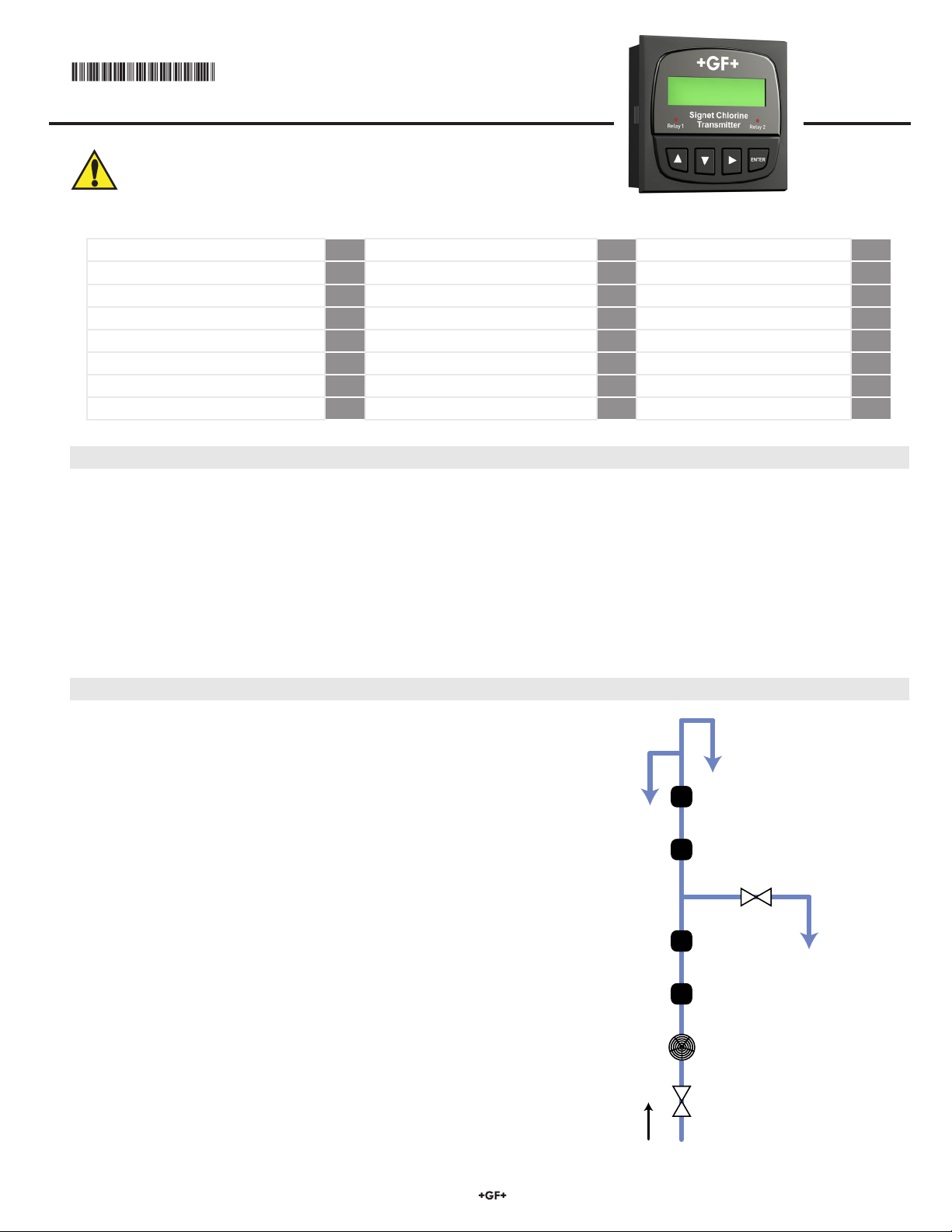
Shut-off Valve
Feed Water
Flow Direction
Strainer (optional)
Flow Meter
Flow Regulator
Discharge
Signet pH Sensor
Signet Chlorine Sensor
Overflow and Vent
Sampling Port and Drain Valve
English
3-8630.090-3 Rev. D 08/10 English
CAUTION!
• Remove power to unit before wiring input or output connections.
• Follow instructions carefully to avoid personal injury or damage
to the transmitter.
1 Description p.1 9 The View Menu p.5 15 Chlorine Calibration p.13
2 System Overview p.1 10 Editing Procedure p.5 15.3 In Process Calibration p.14
3 Start-up Procedure p.2 10.1 Example: Calibrate p.6 16 Output Settings p.14
4 Transmitter Installation p.2 11 Calibrate Menu Denitions p.7 16.1 Current Loop Settings p.14
5 Wiring p.3 12 Options Menu Denitions p.9 16.2 Relay Functions p.15
6 Terminal Identication p.3 13 pH Calibration p.11 17 Troubleshooting p.17
7 Sensor Connections p.4 13.3 Manual pH Compensation p.12 18 Ordering p.19
8 Power and Loop Connections p.4 14 Cl Sensor Conditioning p.12 19 Specications p.20
1. Description
The Signet 8630 ProcessPro® Chlorine Transmitter displays and transmits free chlorine along with pH information when connected
to Signet Amperometric Chlorine Sensors and a Signet pH Sensor.
Features of the 8630 include:
• Displays a wide range of free chlorine concentration inputs from 0 to 5 ppm.
• Displays the full range of the chlorine sensors offered.
• Automatic pH and temperature compensation or manual pH input to calculate accurate chlorine measurements.
• Simple setup and easy customization with the 4 button keypad.
• Dual 4 to 20 mA outputs with two built-in SPDT mechanical relays.
• Easy viewing via the bright backlit LCD display.
2. System Overview
If you have a Signet 463X integrated chlorine panel system, skip to
Section 3. If you have individual components to build your chlorine
system, refer to the diagram to the right for a basic plumbing reference.
View the diagram in relation to gravity with the Sampling Port being
physically lower than the sensors and the Overow being higher than
everything else.
The Discharge and Overow must be a gravity feed. The only head
pressure the chlorine sensor should be subjected to is the water column
to the discharge.
Once the plumbing has been constructed and tested for integrity and
a suitable location for the transmitter found, follow the steps outlined in
Section 3 (New System Start-up Procedure) to get your chlorine system
up and running.
The start-up procedure is identical for integrated panel systems as well.
Basic Plumbing Layout
Page 2
3. New System Start-up Procedure
Your new Signet Chlorine System needs to be calibrated and the chlorine sensor needs to be conditioned prior to use. The following
steps outline the recommended procedure to start up a new system.
Transmitter Installation (Section 4)1.
Wiring (Section 5)2.
Calibrating pH (Section 13)3.
Chlorine Sensor Selection and Conditioning (Section 14)4.
Calibrating Chlorine (Section 15)5.
Conguring Output Settings6. (Section 16)
Note this icon in the manual for
New System Start-up Procedures.
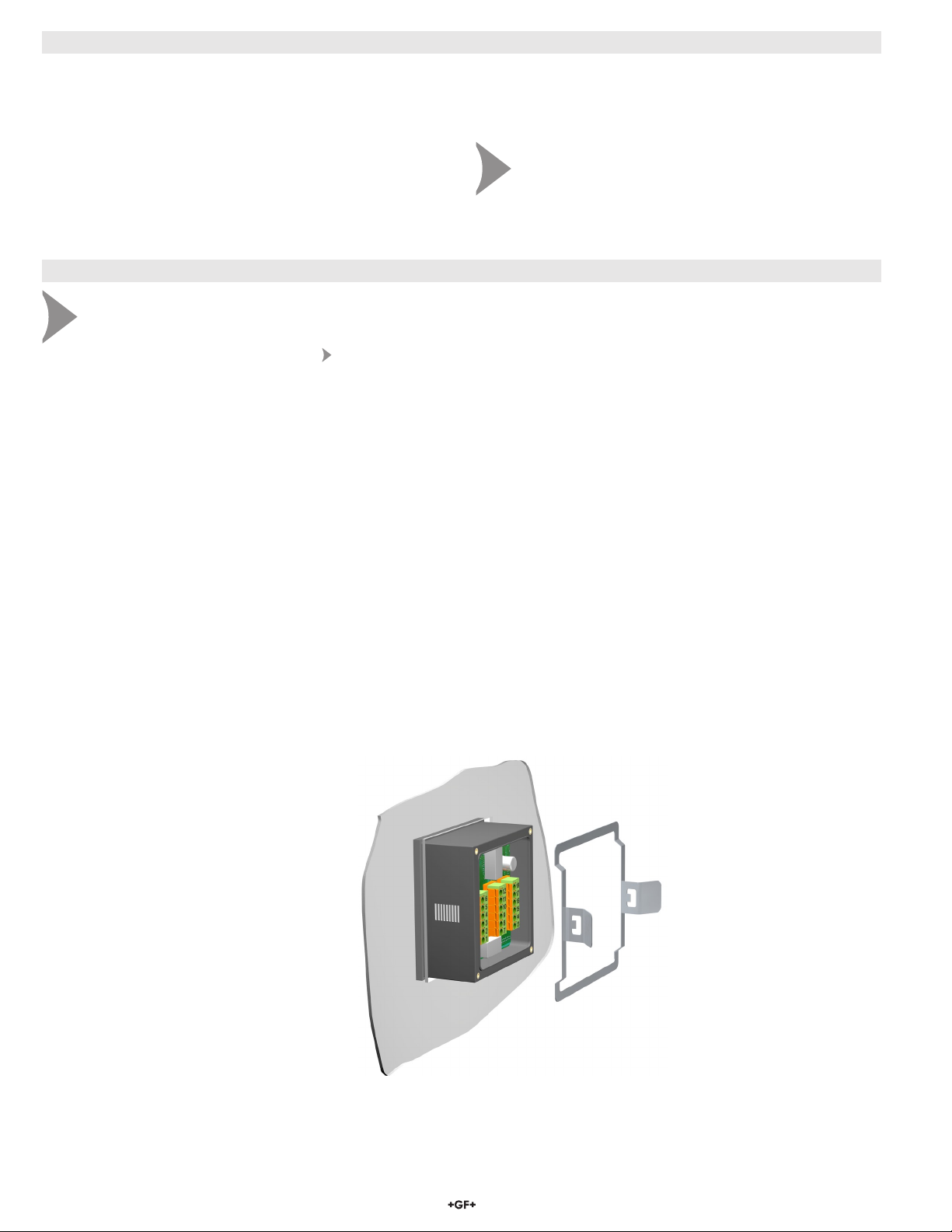
4. Transmitter Installation
System Start-up: Step 1
Prepare the transmitter installation location. If the back of the transmitter is difcult to access when installed, wire it rst, then
install it completely.
Next step: Wiring (see section 5).
The 8630 panel mount transmitter is designed for installation •
using a ¼ DIN Punch.
The panel opening is 92 mm x 92 mm (3.6 in. x 3.6 in.). •
¼ DIN punches are available and recommended for creating •
clean, precise openings quickly and easily in most transmitter
panels.
If a punch is not available, a jigsaw or other cutting tool can be •
used. An adhesive template is provided to help guide the cutting
process. De-burr and smooth the opening with a le.
The recommended minimum clearance on all sides between •
transmitters and panel edges is 25 mm (1 in.).
Panel Installation
Slide the transmitter into the cutout from the front of the 1.
panel with the gasket seated against the ange.
Slide the mounting bracket over the back of transmitter 2.
until the quick-clips snap into the grooves on the side
of transmitter.
To remove, secure the transmitter temporarily with tape from the front
or grip from the rear of the transmitter.
Press the quick-clips outward and remove.
Panel installation
Quick
clip
Mounting
bracket
2 8630-3 Chlorine Transmitter
Page 3
2
1
2
1
2
1
2
1
2
1
2
1
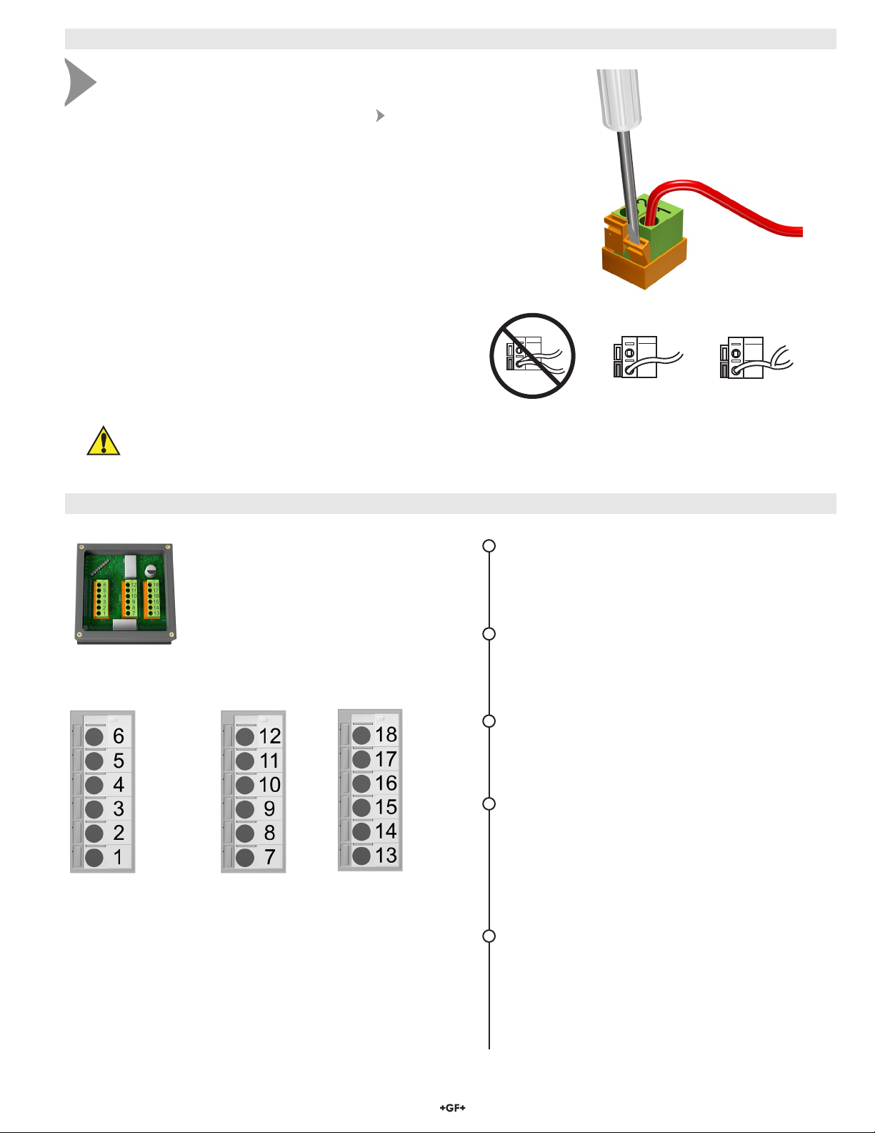
5. Wiring
Loop 2 -
Loop 2
+
System Power
Loop 1
-
System Power
Loop 1
+
AUX
Power
-
AUX
Power
+
Relay 2
(N.O.)
Relay 2
(COM)
Relay 2
(N.C.)
Relay 1
(N.O.)
Relay 1
(COM)
Relay 1
(N.C.)
Ground
Digital
(S3L)
V+
Ground
Digital
(S3L)
V+
System Start-up: Step 2
Wire the transmitter for all connections with the power off. Keep any 4 to 20 mA
and relay actuated output devices that are connected to it ofine at this time.
Next step: Calibrating pH (see section 13).
Wiring Procedure
1. Remove 13 to 16 mm (0.5 to 0.625 in.) of insulation from the
end of the wire to be connected to the transmitter.
2. Press the orange terminal lever all the way down with a
small screwdriver to open terminal jaws.
3. Insert wire into terminal until it bottoms out.
4. Release the orange terminal lever to secure the wire in place.
5. Gently pull on each wire to ensure a good connection.
Wiring Tips:
Do not route the sensor cable in conduit containing AC power wiring. •
Electrical noise may interfere with sensor signal.
Routing the sensor cable in grounded metal conduit can help prevent •
electrical noise and mechanical damage.
Seal the cable entry points to prevent moisture damage.•
Only one wire should be inserted into a terminal.•
Splice double wires outside the terminal.
Caution: Failure to fully open terminal jaws before removing wire may
permanently damage transmitter.
NO YESYES
6. Terminal Identication
The transmitter requires regulated 12 to 24
VDC ±10% from an external power supply.
Maximum current draw is 250 mA.
Power must be supplied to terminals
1 & 3 (+) and 2 & 4 (-).
(N.O.) = Normally Open (no contact)
(N.C.) = Normally Closed (contact)
Terminals 1–2: System Power and Auxiliary Power
Required by the transmitter
• Provides DC power to sensors, relays and the
LCD backlight.
Terminals 3–4: System Power and Loop 1 Power
12 to 24 VDC ±10%
Max. loop impedance: 50 Ω max. @ 12 V
325 Ω max. @ 18 V
600 Ω max. @ 24 V
Terminals 5–6: Loop 2 Power
12 to 24 VDC ±10%
Max. loop impedance: 50 Ω max. @ 12 V
325 Ω max. @ 18 V
600 Ω max. @ 24 V
Terminals 7–12: Relay Outputs
Two mechanical SPDT relays programmable as:
• High or Low setpoint with adjustable hysteresis.
• Proportional Pulse (400 pulses per minute
maximum).
• May be disabled (Off) if not used.
• Auxiliary power (Terminals 1 and 2) MUST be
connected.
Terminals 13–18: Digital (S3L) Input/Output
Two sensors connect here.
13: +5 VDC out to sensor 1 (Chlorine)
14: Digital (S3L) signal in from sensor 1 (Chlorine)
15: Sensor 1 ground
16: +5 VDC out to sensor 2 (pH)
17: Digital (S3L) signal in from Sensor 2 (pH)
18: Sensor 2 ground
38630-3 Chlorine Transmitter
Page 4

7. Sensor Connections
8630 I/O
Te rminals
18
17
16
15
14
13
Sensor Gnd
Digital (S L) data
+5 VDC
Sensor Gnd
Digital (S L) data
+5 VDC
3
3
White
White
Shield
Shield
Red
Red
Black
Black
8630-3 stand-alone application, no loop used. Always splice wires outside of terminals.
Transmitter
Te rminals
Power
Supply
12 to 24 VDC
-
+
Loop 2 -
Loop 2 +
System Power Loop 1 -
System Power Loop 1 +
AUX Power -
AUX Power +
6
5
4
3
2
1
8630-3 stand-alone application, no loop used. Always splice wires outside of terminals.
Transmitter
Te rminals
Power
Supply
12 to 24 VDC
Connection to a PLC with built-in power supply
Internal
PLC
Connection
Connection to a PLC/Recorder, separate supply
-
+
PLC or Recorder
Loop 2 -
Loop 2 +
System Power Loop 1 -
System Power Loop 1 +
AUX Power -
AUX Power +
6
5
4
3
2
1
Transmitter
Te rminals
Loop 2 -
Loop 2 +
System Power Loop 1 -
System Power Loop 1 +
AUX Power -
AUX Power +
6
5
4
3
2
1
6
5
4
3
2
1
Transmitter
Te rminals
Loop 2 -
Loop 2 +
System Power Loop 1 -
System Power Loop 1 +
AUX Power -
AUX Power +
Power
Supply
12 to 24 VDC
-
+
-
+
PLC Te rminals
Channel 1
4 to 20 mA
Power
Supply
12 to 24 VDC
Channel 2
4 to 20 mA
Channel 2
4 to 20 mA
+
-
+
-
+
-
-
+
Channel 1
4 to 20 mA
Transmitter
Te rminals
Power
Supply
12 to 24 VDC
Connection to a PLC with built-in power supply
Internal
PLC
Connection
Example: Two transmitters connected to PLC/Recorder with separate power supply
-
+
PLC or Recorder
Loop 2 -
Loop 2 +
System Power Loop 1 -
System Power Loop 1 +
AUX Power -
AUX Power +
6
5
4
3
2
1
Transmitter
Te rminals
Loop 2 -
Loop 2 +
AUX Power -
AUX Power +
6
5
4
3
2
1
6
5
4
3
2
1
Transmitter
Te rminals
Loop 2 -
Loop 2 +
System Power Loop 1 -
System Power Loop 1 +
AUX Power -
AUX Power +
Loop 2 -
Loop 2 +
System Power Loop 1 -
System Power Loop 1 +
AUX Power -
AUX Power +
6
5
4
3
2
1
6
5
4
3
2
1
Loop 2 -
Loop 2 +
System Power Loop 1 -
System Power Loop 1 +
AUX Power -
AUX Power +
Power
Supply
12 to 24 VDC
-
+
-
+
PLC or Recorder
Channel 3
4 to 20 mA in
Channel 4
4 to 20 mA in
-
+
-
+
Transmitter 1
Te rminals
Transmitter 2
Te rminals
PLC Te rminals
Channel 1
4 to 20 mA
Power
Supply
12 to 24 VDC
Channel 2
4 to 20 mA
Channel 2
4 to 20 mA
+
-
+
-
+
-
+
-
-
+
Channel 1
4 to 20 mA
Channel 1
4 to 20 mA in
Channel 2
4 to 20 mA in
+
-
Power
Supply
12 to 24 VDC
-
+
Note: 8630 transmitters require both terminals 1 & 3 (+) and 2 & 4 (-) to be wired.
Power
Supply
Connection to a PLC with built-in power supply
Internal
PLC
Connection
6
5
4
3
2
1
Transmitter
Te rminals
Loop 2 -
Loop 2 +
System Power Loop 1 -
System Power Loop 1 +
AUX Power -
AUX Power +
-
+
PLC Te rminals
Channel 1
4 to 20 mA
Power
Supply
12 to 24 VDC
Channel 2
4 to 20 mA
+
-
+
-
• The 8630 provides two sets of Input/Output terminals to
connect Digital (S3L) serial data from the chlorine and pH
sensor electronics.
• The total cable length from a sensor to the transmitter must
not exceed 30 m (100 ft).
• Do not route sensor or output cables in conduit containing
AC power wiring.
• Routing cable in grounded metal conduit will help prevent
electrical noise and mechanical damage.
• Seal cable entry points to prevent moisture damage.
• For best performance, ground the sensor shield wires to a
local earth ground at a point near the sensor.
8. System Power and Loop Connections
Signet
pH Sensor
with 3-2750-7
Sensor Electronics
Signet
Chlorine Sensor
with 3-2650-7
Sensor Electronics
4 8630-3 Chlorine Transmitter
Page 5
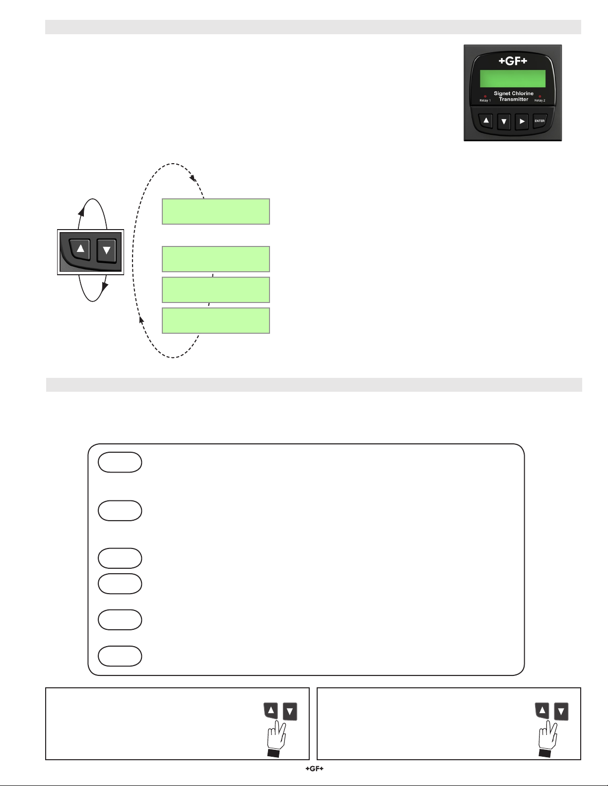
9. The View Menu
The View Menu is displayed during normal operation.•
To select a VIEW display, press the UP or DOWN arrow keys. The selections will scroll in a •
continuous loop. There are four pages to view.
Changing the VIEW display does not interrupt system operations.•
No key code is necessary to change display selection.•
Output settings cannot be edited from the VIEW menu.•
All menus timeout after 10 minutes and return to the previous operating display.•
When editing the CALIBRATE or OPTIONS menus, the transmitter will return to the non-edit•
display after 10 minutes and then the VIEW menu in another 10 minutes if no activity occurs.
8630
Chlorine
FCl: 2.67 ppm
7.10 pH 25.3 °C
The example View menus below return to the default display after 10 minutes.
Cl Raw: 103.8 nA
pH Raw: -5.9 mV
Loop 1 10.68 mA
Loop 2 8.56 mA
Last CAL:
10-18-10
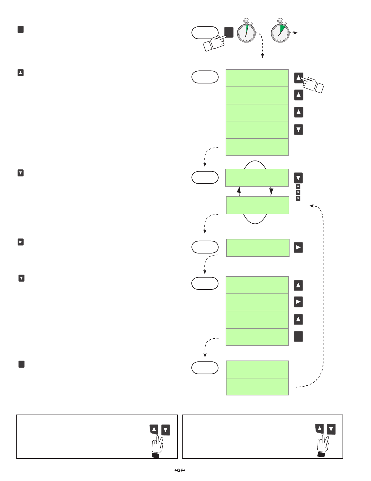
10. Transmitter Editing Procedure
The 8630-3 has two menus the user can edit; CALIBRATE and OPTIONS. •
The CALIBRATE menu allows you to calibrate and initialize sensors, dene current loops and set relay functions.•
The OPTIONS menu allows you to set sensor type, adjust and test current loops, test relays and more.•
Step 1. Press and hold the ENTER key:
• 2 seconds to select the CALIBRATE menu.
• 5 seconds to select the OPTIONS menu.
View chlorine, pH and temperature values from the sensor.
FCl = free chlorine.
Chlorine (nA) and pH raw (mV) signals from the sensors.
For reference only.
View of current loop 1 and loop 2 output.
View of the last calibration date. Editable in the Calibrate Menu.
Step 2. Enter the Key Code.
The Key Code is UP-UP-UP-DOWN keys in sequence.
• After entering the Key Code, the display will show the rst item in the selected menu.
Step 3. Scroll the menu in a loop with the DOWN or UP arrow keys.
Step 4. Press the RIGHT ARROW key to select the menu item to be edited.
• The rst display element will begin ashing.
Step 5. Press the UP or DOWN keys to edit the ashing element.
• The RIGHT ARROW key advances the ashing element.
Step 6. Press the ENTER key to save the new setting and return to Step 3.
Made an Error?
Press the UP and DOWN keys simultaneously
while any element is ashing. This will recall the
last saved value of the item being edited and will
return you to Step 3.
Finished Editing?
Press the UP and DOWN keys simultaneously
after saving the last setting to return to view menu.
58630-3 Chlorine Transmitter
Page 6
ENTER
ENTER
ENTER
2s 5s
ENTER
ENTER
ENTER
10.1 Example: Calibraton
ENTER
ENTER
ENTER
ENTER
ENTER
ENTER
Access the CALIBRATE Menu:
The CALIBRATE and OPTIONS menus require a KEY CODE.
Press and hold the ENTER key for 2 seconds to access the
CALIBRATE menu.
Enter the Key Code:
Pressing the UP, UP, UP, DOWN keys in sequence unlocks the
display and the rst menu item will appear. If no key is pressed
for 5 minutes while the display is showing "Enter Key Code", it will
return to the VIEW menu.
Step 1.
Step 2.
(Hold)
OPTIONS menuOR
CALIBRATE menu
CALIBRATE:---Enter Key Code
CALIBRATE:--Enter Key Code
CALIBRATE:-Enter Key Code
CALIBRATE:Enter Key Code
Cl Zero
Calibration: >
Scroll the Menu:
Press the DOWN or UP keys to scroll through the Menu.
Refer to pages 7 and 8 for complete listing of these items.
While in this mode, pressing the UP and DOWN keys
simultaneously will return the display to the VIEW menu.
If no key is pressed for 10 minutes, the display will return to
the VIEW menu.
Select the item to be edited:
In this example, "Last Cal" (last calibration date) is chosen to edit.
Pressing the RIGHT arrow key selects the menu item and enters
the screen into edit mode.
Edit the ashing element:
This is the edit mode.
The UP or DOWN keys change the ashing element.
The RIGHT arrow key advances the ashing element in a
continuous loop. In this example, the Last Cal date was
changed from 09-18-09 to 10-18-09.
All output functions remain active during editing.
Only the ashing element can be edited.
Step 3.
Step 4.
Step 5.
Cl Zero
Calibration: >
Last Cal:
09-18-09 >
Example
Last Cal:
09-18-09 >
Last Cal:
09-18-09
Last Cal:
19-18-09
Last Cal:
19-18-09
Last Cal:
10-18-09
Press ENTER to save the new value.
When you have set your desired value, pressing the
ENTER key stores the value on the screen, making it
immediately available to output functions and exits you back
to Step 3.
Made an Error?
Press the UP and DOWN keys simultaneously
while any element is ashing. This will recall the
last saved value of the item being edited and
Step 6.
Press the UP and DOWN keys simultaneously
after saving the last setting to return to the View
Menu.
Last Cal:
Saving
Last Cal:
10-18-09
Finished Editing?
return you to Step 3.
6 8630-3 Chlorine Transmitter
Page 7

11. Calibrate Menu Denitions
ENTER
ENTER
ENTER
The menus below are displayed here in the order seen when scrolling down through the Calibrate Menu.
NOTE:
Although the Calibrate Menu can be navigated upwards or downwards, it is best to navigate downwards when editing •
Current Loop and Relay settings as previous entries can inuence subsequent menus.
Chlorine and pH calibration screens will be shown only when a valid sensor is detected.•
Press the Down Arrow key to
scroll through the menus
Calibrate Menus
- Factory settings shown -
Chlorine Units:
ppm >
Cl Zero
Calibration: >
Cl In Process
Calibration: >
Cl Temperature
Calibration: >
Reset Cl to
Factory Cal: >
NOTE: The next two pH calibration screens will be shown only when a valid pH sensor is detected.
pH Standard
Calibration: >
This is the rst screen. Choose units of measurement of ppm or mg/l.
When > is pressed, the “live” readings are shown. The nA value is displayed, but cannot be
edited and is used for diagnostic and calibration purposes. When in Edit Mode, pressing Enter
stores the displayed value as your zero reference. Example on Section 15.
Enter process chlorine value determined from a DPD test kit here. Example on Section 15.
Enter process temperature from a reference thermometer: °C or °F. Units are set up in the
Options Menu. Example on Section 15.
This menu resets Cl readings, Zero Calibration and temperature back to Factory Calibration.
WARNING! User entered Cl calibration settings will be lost.
Set pH offset value. This applies a linear offset to the pH measurement.
Example on Section 13.
Press the Right Arrow key to enter
edit mode
Description
Press the Enter key to save your
settings
pH Slope
Calibration: >
Reset pH to
Factory Cal: >
Loop 1 Source:
Chlorine >
Loop 1 Rng: ppm
0.00 5.00 >
Loop 2 Source:
pH >
Loop 2 Rng: pH
00.0 14.00 >
Applies a slope to the pH measurement. The slope and standard value must be at least 2 pH
units apart. Example on Section 13.
Reset pH standard, slope and temperature back to Factory Calibration.
WARNING! User entered pH calibration settings will be lost.
Current Output Functions
Choose chlorine or pH for this 4 to 20 mA current loop. Example on Section 16.
Select the minimum and maximum values for the current loop output. Units are derived from
Loop 1 Source. If the Source 1 is changed, be sure to re-edit this page.
Choose pH or chlorine for this 4 to 20 mA current loop.
Select the minimum and maximum values for the current loop output. Units are derived from
Loop 2 Source. If Source 2 is changed, be sure to re-edit this page.
78630-3 Chlorine Transmitter
Page 8

Calibrate Menu continued
Relay Functions
Verify all relay settings if the Relay Source is changed.
Relay 1 Mode:
Off >
If Low or High Mode was chosen:
Relay 1 Source:
Chlorine >
Relay 1 Setpnt:
0.00 ppm >
Relay 1 Hys:
0.20 ppm >
Relay 1 Delay:
0.0 secs >
If Window Mode was chosen:
Relay 1 Source:
Chlorine >
Relay1 Rng: ppm
0.00 5.00 >
Relay 1 Hys:
0.20 ppm >
Choose mode of operation: Off, Low, High, Window, or Pulse. If Off, all subsequent Relay 1
functions are inactive and not visible. Example on Section 16.3.
Choose chlorine or pH for Relay 1.
In Low or Hi Mode, Relay 1 will be activated when the process reaches this value.
Units of measure reect Relay 1 Source.
Relay 1 will be deactivated at Relay 1 Setpoint ± this hysteresis setting depending on
High or Low Setpoint selection.
Set the time delay for Relay 1 to activate after reaching the Setpoint.
Range: 0 to 6400 seconds.
Choose chlorine or pH for Relay 1.
Enter the range where Relay 1 will activate above and below this setpoint.
Relay 1 will be deactivated at Range setpoints ± this hysteresis setting.
Relay 1 Delay:
0.0 secs >
If Pulse Mode was chosen:
Relay 1 Source:
Chlorine >
Relay1 Rng: ppm
0.00 5.00 >
Relay1 PlsRate:
120 pulses/min >
Relay 2 Mode:
Off >
If Low or High Mode was chosen:
Relay 2 Source:
pH >
Relay 2 Setpnt:
0.00 pH >
Relay 2 Hys:
0.20 pH >
Set time delay for Relay 1 to activate after reaching the setpoints set in Relay 1 Range.
Choose chlorine or pH for Relay 1.
Enter the range where Relay 1 will activate above and below this setpoint.
Set the maximum pulse rate. Range: 1 to 400 pulses/min.
Choose Relay 2 mode of operation: Off, Low, High, Window, or Pulse.
To disable this relay choose Off.
Choose pH or chlorine for Relay 2. This menu screen and all subsequent Relay 2 screens
below do not appear if Relay 2 Mode is set to Off.
In Low or High Mode, Relay 2 will be activated when the process reaches this value.
Units of measure reect Relay 2 Source.
Relay 2 will be deactivated at Relay 2 Setpoint ± this hysteresis setting depending on
High or Low Setpoint selection.
Relay 2 Delay:
0.0 secs >
8 8630-3 Chlorine Transmitter
Set the time delay for Relay 2 to activate after reaching the Setpoint.
Range: 0 to 6400 seconds.
Page 9

ENTER
ENTER
ENTER
Calibrate Menu continued
If Window Mode was chosen:
Relay 2 Source:
pH >
Relay 2 Rng: ppm
0.00 5.00 >
Relay 2 Hys:
0.20 ppm >
Relay 2 Delay:
0.0 secs >
If Pulse Mode was chosen:
Relay 2 Source:
pH >
Relay2 Rng: pH
0.00 14.0 >
Relay2 PlsRate:
120 pulses/min >
Find New
Sensor(s): >
Choose pH or chlorine for Relay 2.
Enter the range where Relay 2 will activate above and below this setpoint.
This relay will be deactivated at Relay 2 Range setpoints ± this hysteresis.
Set the time delay for Relay 2 to activate after reaching the setpoints set in the
Relay 2 Range.
Choose pH or chlorine for Relay 2.
Enter the range where Relay 2 will activate above and below this setpoint.
Set the maximum pulse rate. Range: 1–400 pulses/min.
Required only when a new sensor is changed while the power is on. Choose Yes or No.
Last Cal
10-18-09 >
12. Options Menu Denitions
Press the Down key to scroll
through the menus
Options Display
(Factory settings shown)
Contrast:
3 >
Cl Sensor Type:
Free Cl >
pH Input
Sensor >
If Manual pH input was chosen:
Manual pH Value
7.000 pH
Adjust the LCD contrast for best viewing. A setting of 1 is lower contrast, 5 is higher.
Select the chlorine sensor: Free Cl.
Choose Manual or Sensor. If Sensor is chosen, the pH value from the connected pH sensor will
be used. Choose Manual to enter a pH value manually when no sensor is connected.
Edit the calibration date.
End of Calibrate Menu
Press the Right Arrow key to enter
edit mode
Description
Enter your pH value here if a pH sensor is not connected.
Press the Enter key to save your
settings
Temp Display:
°C >
Averaging:
Off >
Choose units of °C or °F.
OFF gives the fastest response to input changes. LOW = 4.5 seconds, HIGH = 9 seconds of
averaged response. Increase averaging to steady the display.
98630-3 Chlorine Transmitter
Page 10

Options Menu continued
Options Display
(Factory settings shown)
Decimal:
***.** >
Loop 1 Adjust:
4.00 mA >
Loop 1 Adjust:
20.00 mA >
Loop2 Adjust:
4.00 mA >
Loop2 Adjust:
20.00 mA >
Test Loop 1:
>
Test Loop 2:
>
Test Relay 1:
>
Description
Select the decimal point for the display. Maximum of 2 decimal places.
Adjust the minimum current output for Loop 1. The display value represents the precise
current output. Range: 3.80 mA to 5.00 mA.
Adjust maximum current output for Loop 1. Range: 19.00 mA to 21.00 mA.
Adjust the minimum current output for Loop 2. Range: 3.80 mA to 5.00 mA.
Adjust maximum current output for Loop 2. Range: 19.00 mA to 21.00 mA.
Press UP or DOWN keys to manually output any current value from 3.6 mA to 21.00 mA to
test Loop 1 output.
Press UP or DOWN keys to manually output any output current value from 3.6 mA to
21.00 mA to test Loop 2 output.
Press UP or DOWN keys to manually toggle Relay 1 Off and On. The left LED on the front
of the transmitter conrms operation.
Test Relay 2:
>
Read Sens Data:
No >
If Yes was chosen:
Cl Sensor S/N:
xxxxxxxxx
Cl Type & Range:
2630 xxx.x ppm
Zero Cal: ppm&nA
xxx.xx xxxx.x
In Proc: ppm&nA
xxx.xx xxxx.x
Temp at Cal:
xxxx.x °C
pH at Cal:
xxx.xx pH
Temp Offset:
xxxx.x °C
Press UP or DOWN keys to manually toggle Relay 2 Off and On. The right red LED on the
front of the transmitter conrms operation.
If "YES" is selected the following (Read Only) screens will be shown.
If "NO" then this menu ends the Options Menu.
View the sensor serial number.
Identify the chlorine sensor type connected and its ppm range.
View user entered Zero Calibration data in ppm and nA.
View user In-Process Calibration value when it was entered in the Calibrate Menu.
Temperature recorded during user In-Process Calibration.
pH value recorded during user In-Process Calibration.
Temperature offset calculated from user entered temperature calibration from Calibrate Menu.
Elapsed Time:
xxxxx. hrs
Low & High: °C
-xxxx.x +xxxx.x
10 8630-3 Chlorine Transmitter
Total hours of operation.
Lowest and highest temperatures the Cl sensor has been subjected to during operation.
End of Options Menu
Page 11

13. pH Sensor Calibration
ENTER
ENTER
ENTER
2s 5s
ENTER
ENTER
ENTER
ENTER
ENTER
ENTER
System Start-up: Step 3
If a pH sensor is part of the system, it must be calibrated before use and before the chlorine sensor is calibrated. If a pH sensor is
not available but pH determination is necessary, measure process pH with a separate test and enter the value in the Options Menu.
Next step: Chlorine Sensor Conditioning (see section 14).
Refer to your pH sensor manual.
The pH sensor needs to be calibrated against two different pH
buffer references to calibrate the offset (standard) and slope.
Electrode offset is any deviation from 0 mV in a pH 7 buffer at 25 °C.
Slope is the ratio of mV to pH units.
Always keep any output devices ofine when calibrating. •
13.1 pH Offset (Standard)
The transmitter must be powered on and the pH sensor must be
connected.
Turn off the water ow through the system, then remove the 1.
pH sensor from its ow cell.
Using pH buffer 7.0, place enough pH buffers into a 2.
clean calibration cup, supplied with the pH calibration kit
3-2700.395 (159 001 605), to cover the tip of the electrode.
Pour distilled water in another clean cup for rinsing the 3.
electrode between buffers
Place the pH sensor in the pH 7.0 buffer and allow the 4.
reading to stabilize.
Example: Set pH Standard to 7.00.
Go to the Calibrate Menu.5.
EXAMPLE
Scroll down ▼ 5 menus to the 6. pH Standard menu.
Press ► to enter Edit Mode.7.
Enter the pH value of the buffer that the electode is placed in; 8.
7.00 in this case. Note: the mV readings will not change.
Press the Enter button to save the setting.9.
Exit to the View Menu. ▲▼10.
EXAMPLE
Step 4
5
pH buffer value
entered here
FCl: 2.67 ppm
7.11 pH 25.3°C
(Hold)
pH Standard
6
Calibration: >
7
pH Standard Cal:
8
07.00 pH/ 0 mV
View Menu
5X
Calibrate Menu
13.2 pH Slope
Remove the pH sensor from the rst buffer solution and rinse 1.
it in distilled water.
Place the pH sensor in a different buffer solution (example: 2.
pH 4.01). The pH standard and slope must be at least 2 pH
units apart.
Note the pH reading on the View Menu and allow it to 3.
stabilize.
Example: Set pH slope to 4.01.
Go to the Calibrate Menu.4.
EXAMPLE
Scroll down ▼ 6 menus to the 5. pH Slope menu.
Press ► to enter Edit Mode.6.
Enter the pH value of the buffer that the electode is placed in; 7.
4.01 in this case. Note: the mV readings will not change.
Press the Enter button to save the settings.8.
Exit to the View Menu. ▲▼9.
Replace the pH sensor back into its ow cell.10.
Calibration is complete for the pH sensor.
EXAMPLE
Step 3
5
6
7
pH buffer value
entered here
FCl: 2.67 ppm
4.12 pH 25.3°C
pH Slope
Calibration: >
pH Slope Cal:
04.01 pH/ +177 mV
View Menu
Calibrate Menu
118630-3 Chlorine Transmitter
Page 12

13.3 Manual pH Compensation
ENTER
ENTER
ENTER
ENTER
ENTER
ENTER
pH calibration continued
If the pH of the application is stable, then the pH of the application
can be entered manually and will be used to calculate the chlorine
measurements.
EXAMPLE
Example: Change the pH input from Sensor to Manual and enter
a pH value of 7.22.
Go to the Options Menu.1.
EXAMPLE
Scroll down ▼ 2 menus to the 2. pH Input menu.
Press ► to enter Edit Mode.3.
Choose 4. Manual and press Enter.
Scroll down ▼ 1 menu to the 5. Manual pH Value menu.
Press ► to enter Edit Mode.6.
Enter your new process pH value:7. 7.22.
Press the Enter button to save the setting.8.
Exit to the View Menu.9.
14. Chlorine Sensor Conditioning
System Start-up: Step 4
A new chlorine sensor or one that has had the electrolyte or membrane replaced must be condtioned to generate stable and
accurate readings. To condition a chlorine sensor, the sensor and sensor electronics must be installed and powered and must
also have water ow across the membrane:
Next step: Calibrating Chlorine (see section 15).
Step 2
pH Input
Sensor >
pH Input
4
Sensor Manual
pH Input
Manual >
Manual pH Value
5
7.220 pH
Options Menu
Manual chosen
New pH value entered
Chlorine Sensor Conditioning
Turn on and adjust water ow rate. Condition a new chlorine 1.
sensor for 4 hours. Conditioning time for a membrane cap
replacement or electrolyte rell is 2 hours.
Keep any 4 to 20 mA devices or relay actuated output devices 2.
that connect to the transmitter ofine.
12 8630-3 Chlorine Transmitter
Page 13

15. Chlorine Sensor Calibration
ENTER
ENTER
ENTER
ENTER
ENTER
ENTER
System Start-up: Step 5
Chlorine sensors need to be calibrated for accuracy. After the 4 hour conditioning period, Temperature Calibration, Zero Point
Calibration and In-Process Calibration needs to be performed. Any 4 to 20 mA or relay output devices should be ofine.
Next step: Setting Output Settings (see section 16).
15.1 Chlorine Sensor Temperature Calibration
The temperature element inside the chlorine sensor needs to be
calibrated. Use a reference thermometer at the same temperature
and in the same medium as the immersed sensor.
Example: Set the calibrated temperature to 25.3 ºC.
EXAMPLE
Step 2
Cl Temperature
Calibration: >
Calibrate Menu
Go to the Calibrate Menu.1.
EXAMPLE
Scroll down ▼2. 3 menus to the Cl Temperature menu.
Press ► to enter Edit Mode.3.
Enter the temperature reading. 4. Example: 25.3.
Press the Enter button to save the setting.5.
Exit to the View Menu.6.
15.2 Zero Point Calibration
The chlorine sensor needs to be calibrated against two chlorine
references: zero chlorine and the process chlorine. Typically the zero
point calibration is very stable. Calibration must be done with every
new sensor and any time a membrane cap is replaced.
Ensure any output devices are ofine and disable relays.1.
Turn off the water ow and remove the powered chlorine sensor 2.
with the electronics still attached.
Place the sensor tip in distilled water.3.
Wait until the reading stabilizes, then save the calibration. 4.
Stirring the sensor in water is not necessary, but allows the
signal to stabilize faster.
Example: Set the Zero Point Calibration at 1.0 nA.
Go to the Calibrate Menu.5.
EXAMPLE
Scroll down ▼6. one menu to the Cl Zero menu.
Press ► to enter Edit Mode. 7. You will see ashing the live sensor
readings in ppm and nA. These readings cannot be modied, but
can only be saved as dispalyed.
Press the Enter button at the lowest reading to save the setting 8.
or press to escape without changes.
Exit to the View Menu.9.
4
New temp. value
EXAMPLE
Step 6
8
Cl Temp: Cal
+025.3 °C
Cl Zero:
Calibration >
Zero Cal: ppm&nA
0.20 / 001.0
Lowest value noted for
Zero Cal.
Calibrate Menu
After Zero Point Calibration is complete, replace the sensor back 10.
into the ow cell and turn the water ow back on.
Wait until the chlorine readings stabilize once again, then perform 11.
a chlorine In-Process Calibration.
The signal level during a Zero Point
Calibration must be at least 1 nA away
from the In-Process Calibration point.
138630-3 Chlorine Transmitter
Page 14

15.3 In-Process Calibration
ENTER
ENTER
ENTER
Take a water sample from the Sampling Port (after purging it) 1.
from a stabilized and running system.
Use this sample to measure the chlorine content with a 2.
The signal level during an In-Process
Calibration must be at least 1 nA away
from the previous Zero Calibration point.
colorimetric DPD test kit (not included). Refer to the DPD kit
instructions on how to perform this test.
Record the test results.3.
EXAMPLE
Example: Set the Chlorine In-Process to 2.67 ppm.
Go to the Calibrate Menu.4.
EXAMPLE
Step 5
Cl In Process
Calibration: >
Scroll down ▼5. 2 menus to the Cl In-Process menu.
Press ► to enter Edit Mode.6.
Enter the chlorine reading determined from the DPD test into the 7.
edit screen: 2.67 ppm. The Cl ppm is editable and must be at
least 0.2 ppm.
In Proc: ppm&nA
7
2.67 / 103.8
Press the Enter button to save the setting.8.
Exit to the View Menu.9.
DPD Cl ppm value
entered here.
Calibration is complete for the chlorine sensor.
16. Output Settings - Current Loops and Relays
System Start-up: Step 6 (last step)
Congure the current loop and relay functions if applicable. The current and relay outputs can be tested in the Options Menu.
This concludes the system start-up procedure.
Calibrate Menu
16.1 Current Loop Settings
Current outputs are passive outputs that can be spanned in the
forward and reverse direction. Example: 0 to > 5 or 5 to > 0.
Example: Set a current loop source as chlorine and the
operational range to 0 to 5 ppm.
Go to the Calibrate Menu.1.
EXAMPLE
Scroll down ▼2. to the Loop 1 Source menu.
Press ► to enter Edit Mode.3.
Choose either the chlorine or pH sensor as the source that will 4.
control this loop: Chlorine.
Press the Enter button to save the setting.5.
Scroll down ▼6. 1 menu to the Loop 1 Rng menu.
Press ► to enter Edit Mode.7.
Select the minimum and maximum process values for the current 8.
loop output: 0 to 5 ppm.
Press the Enter button to save the setting.9.
Exit to the View Menu. 10.
EXAMPLE
Step 2
Loop 1 Source:
Chlorine >
Set and save
Loop 1 Rng: ppm
6
0.00 5.00 >
Set and save
Calibrate Menu
14 8630-3 Chlorine Transmitter
Page 15

16.2 Mechanical Relay Functions
Hysteresis
Time
High Setpoint
Process
Hysteresis
Time
Low Setpoint
Process
Time
High Limit
Hysteresis
Hysteresis
Low Limit
Process
Window
Time
Time
Time
Hysteresis
Hysteresis
Relay energized
Relay de-energized
14 mg/l
Output (pulses per minute)
Ending
Point
Input (mg/l)
Starting
Point
0
20
40
60
80
100
Output (pulses per minute)
StartEnd
Time
0
20
40
60
80
100
Pulse
Hysteresis
Time
High Setpoint
Process
Time
Process
Time
High Limit
Hysteresis
Hysteresis
Low Limit
Process
Window
Output Settings continued
The 8630 relays are selectable and congurable and can be used
as switches that respond when the process value moves above or
below a user dened setpoint. They can be used for Low Alarm,
High Alarm or Proportional Pulse triggering related to the process
value. Relay functions, hysteresis and time delay settings are set
up in the CALIBRATE menu and can be tested in the OPTIONS
menu.
Low Setpoint:
Relay is activated when the measured value is less than
the setpoint.
High Setpoint:
Relay is activated when the measured value is higher than
the setpoint.
Window:
Relay is off within the window of two setpoints minus the
hysteresis. Relay is activated when the value is higher or lower
than the high and low setpoint.
Pulse-frequency Operation:
The transmitter can output a pulse at the rate dened by the
settings in the CALIBRATE menu and the sensor input. The
maximum pulse square wave output from the relays is 400 pulses
per minute. Example usage would be to control solenoid operated
dosing pumps.
Example: As the process value drops below the setpoint (4 mg/l)
the output will start pulsing in relation to the process value, the
maximum pulse endpoint and the programmed pulses/minute.
The pulse rate will increase as the process value decreases and
approaches the programmed endpoint. This functionality can be
used to precisely control the process.
• The output will be 0 pulses/minute when the input value is
greater than 4 mg/l.
• The output will be 35 pulses/minute when the input value is
3 mg/l.
• The output will be 100 pulses/minute when the input value is
1 or less.
The starting point, endpoint and maximum pulse rate are select able
in the CALIBRATE menu.
158630-3 Chlorine Transmitter
Page 16

16.3 Relay Settings
Time
Time
Time
Hysteresis
Hysteresis
Relay energized
Relay de-energized
1.00
1.30
Time
Cl ppm
Time Delay
Low
Setpoint
Output Settings continued
Example: Set a relay to trigger on at a low setpoint of 1.0 ppm
with a time delay of 15 seconds and turn off at 1.30 ppm.
Once a setting is saved it becomes immediately active.•
Go to the Calibrate Menu.1.
EXAMPLE
Scroll down ▼2. to the Relay 1 Mode menu.
Press ► to enter Edit Mode.3.
Scroll down ▼4. and choose Low.
Press Enter.5.
Scroll down ▼6. to the Relay 1 Source menu. The default is
Chlorine which is what we want in this example.
Scroll down ▼7. to the Relay 1 Setpnt menu.
Press ► to enter Edit Mode.8.
Set the ppm value to trigger the relay:9. 1.00 ppm.
Press Enter.10.
Scroll down ▼11. to the Relay 1 Hys menu.
Press ► to enter Edit Mode.12.
Set the hysteresis (dead zone) for this relay. This affects the turn 13.
off only: 0.3 ppm.
Press Enter.14.
Scroll down ▼15. to the Relay 1 Delay menu.
Press ► to enter Edit Mode.16.
Set the turn-on delay in seconds for the relay: 17. 15 secs.
Press Enter.18.
Exit to View Mode.19.
EXAMPLE
Step 4
Relay 1 Mode:
Low >
Set and save
Relay 1 Source:
6
Chlorine >
Set and save
Relay 1 Setpnt:
9
1.00 ppm >
Set and save
Calibrate Menu
Relay function can be tested in the Options Menu.•
13
17
Relay 1 Hys:
0.30 ppm >
Set and save
Relay 1 Delay:
15.0 secs >
Set and save
16 8630-3 Chlorine Transmitter
Page 17

17. Troubleshooting
Several factors can cause irregular or incorrect readings. The rst thing to check is to verify that the transmitter and sensors have been
installed correctly. The list below outlines possible causes and remedies.
Transmitter Troubleshooting
Problem Possible Cause Remedies
Transmitter does not turn on. Incorrect wiring.
No or low voltage supplied to transmitter.
Blown fuse.
Bad wire connections or splices.
Display screen is too dark or too dim. Contrast set incorrectly or ambient
temperature is too high.
LCD backlight, relays and sensors do
not work.
Incorrect temperature reading. Faulty chlorine sensor.
Digital or Current output is erratic. Electrical noise interfering with the
Output is not zero when electrode is
placed in non-chlorinated water.
4 to 20 mA output is incorrect. 4 to 20 mA is not scaled same as Loop
No power supplied to terminals 1 and 2. Transmitter requires power to terminals
Bad sensor connection.
measurement.
Sensor malfunction.
Electrode not properly conditioned.
Noise interfering with the measurement.
Calibration incorrect.
device.
Loop device is not scaled same as sensor.
Check wiring, power supply and wiring
connections.
Adjust contrast in Options Menu.
1, 2, 3 and 4.
Check connections, or replace sensor.
Ensure system is properly grounded.
See Sensor Troubleshooting.
Condition new sensor for 4 hours. Cap
replacement or electroyte reill: 2 hours.
Properly ground system.
Replace sensor.
Re-span loop device to match sensor.
Chlorine Sensor Troubleshooting (see 2630 sensor manual)
Incorrect readings Sensor conditioning time too short. Run for 4 hours before calibrating.
Membrane cap damaged or contaminated. Clean or replace cap.
Interference from water contaminants. See technical data (Section 19).
Low ow rate. Check ow.
Air bubbles on membrane. Install ow cell vertically with upwards ow.
pH outside working range
(see technical data, Section 19).
Low or no electrolyte in sensor. Fill sensor with electrolyte.
Membrane cap loose. Inspect/tighten (do not use tools).
Only combined chlorine present when
measuring free chlorine.
Sensor not making good contact with
electronics.
Defective sensor. Replace.
No pH compensation being used. Manually enter pH value in Options or
Cl sensor not calibrated. Calibrate Cl sensor.
Check pH.
Validate with DPD test.
Inspect and reconnect.
calibrate pH sensor.
178630-3 Chlorine Transmitter
Page 18

17.1. Error Messages
The 8630 error warnings are self-explanatory. An error message can appear under the following circumstances:
User input value is out of range •
Poor electrical connection •
Sensor is not connected or detected•
Temperature error•
Incorrect sensor type chosen in the Options Menu•
Two calibration points are too close together when calibrating pH or chlorine.•
Error Messages Problem Possible Cause Remedies
Sens Data Error
Cl sensor data memory error. Cl sensor is not connected.
Damaged sensor.
Check Cl sensor wiring and
connection.
CHK Cl SENSOR
CHK pH SENSOR
Out Of Range
CHECK SENSOR
Standard Too Close
To Slope!
Slope Too Close
To Standard!
Signal Too Close
To Other Cal Pt
Cl Value Must Be
> = 0.2 ppm
Cl sensor is not detected. Cl sensor not connected.
Wrong wiring.
Damaged sensor.
pH sensor is not detected. pH sensor is not connected.
Wrong wiring.
Damaged sensor.
pH calibration error. pH values are out of range. Enter proper values during
pH standard calibration point is
too close to slope point.
pH slope calibration point is too
close to standard point.
The signal level of Cl for Inprocess calibration is too close
to the Zero Cal Point.
The Cl value entered during Inprocess calibration is too small.
Wrong data is entered. pH
buffer solution used has value
too close to standard point.
Wrong data is entered. pH
buffer solution used has value
too close to standard point.
The Cl solution used for Inprocess calibration is too close
to Zero Cal. These two points
must be 1 nA apart.
Wrong data is entered. The
value entered must be at least
0.2 ppm (mg/l).
Check wiring and connection.
Check wiring and connection.
calibration.
Re-enter correct data.
Use proper buffer solution at
least 2 pH units apart from
slope buffer solution.
Re-enter correct data.
Use proper buffer solution at
least 2 pH units apart from
standard buffer solution.
Use proper solution at least 1
nA apart.
Re-enter correct value.
The signal level during Zero
Signal Too High
Must Be =< 10 nA
calibration is too high. Signal
must be equal or less than
10 nA.
pH value is too high. During In-Process calibration
pH Too High
Must be =< 9
pH value is too low. During In-process calibration
pH Too Low
Must be >= 4
FCl= _ _ _ _ _ _
pH sensor is not detected. pH sensor is not connected.
CHK pH Sensor
18 8630-3 Chlorine Transmitter
The sensor is not stabilized.
The solution used has too much
chlorine.
the pH value is too high and
must be less than or equal to 9.
the pH value is too low and
must be greater than or equal
to 4.
Wrong wiring.
Damaged pH sensor.
Wait for sensor stabilization.
Check solution to ensure that
the chlorine level is close to
zero ppm (mg/l).
Check pH.
Check pH.
Check wiring and connections
or change pH input to Manual in
Options Menu.
Page 19

18. Ordering Information
Mfr. Part No. Code Description
3-8630-3P 159 001 673 Panel mount chlorine and pH transmitter
Accessories and Replacement Parts
Mfr. Part No. Code Description
3-2630.391 159 001 674 Free Chlorine electrolyte, 30 ml
3-2630.392 159 001 675 Free Chlorine replacement membrane (1)
3-2630.396 159 001 676 Free Chlorine replacement kit - (2) electrolyte and (2) membranes
3-0700.390 198 864 403 pH Buffer Kit (1 each 4, 7, 10 pH buffer in powder form, makes 50 mL)
3822-7004 159 001 581 pH 4.01 buffer solution, 1 pint (473 ml)
3822-7007 159 001 582 pH 7.00 buffer solution, 1 pint (473 ml)
3822-7010 159 001 583 pH 10.00 buffer solution, 1 pint (473 ml)
3-2700.395 159 001 605 Calibration kit: included 3 polypropylene cups, box used as cup stand, 1 pint
pH 4.01, 1 pint pH 7.00
198630-3 Chlorine Transmitter
Page 20

19. Specications Signet 3-8630-3 Chlorine Transmitter
92 mm
(3.6 in.)
97 mm
(3.8 in.)
56 mm
(2.2 in.)
41 mm
(1.6 in.
)
Optional
Rear
Cover
SIDE VIEW
FRONT VIEW
96 mm
(3.8 in.)
96 mm
(3.8 in.)
SIDE VIEW
Field Mount with 8050 Universal base
106 mm (4.2 i n.)
42 mm
(1.7 in.)
64 mm
(2.5 in.)
82 mm
(3.23 in.)
8050
8630
Dimensions
General
Compatible Sensors:
Signet 3-2630-2 Free Chlorine Sensor
Signet 3-2724-00 Flat pH Sensor
Compatible Electronics
Signet 3-2650-7 Amperometric Electronics
Signet 3-2750-7 pH Sensor Electronics
Materials:
Case: PBT
Panel case gasket : Neoprene
Window: Polyurethane-coated polycarbonate
Keypad: Silicone rubber
Display:
LCD: Backlit alphanumeric 2 x16 dot matrix
Keypad: Silicone rubber
Display update rate: 1 second
Contrast: User selected, 5 levels
Performance
System Operational Ranges/Limits (Chlorine):
Free Cl
0 ppm to 5 ppm
pH Input Range:
0 pH to 14 pH
Chlorine Compensation Range:
pH: 5.0 pH to 9.0 pH (Free Chlorine)
Temperature range: 0 °C to 45 °C (32 °F to 113 °F)
Maximum Cable Distance (sensor to transmitter):
Digital (S3L): 30 m (100 ft) maximum
4 to 20 mA output: 305 m (1000 ft) maximum
Electrical
Power Supply Requirement:
12 to 24 VDC ±10% regulated, 250 mA max current
Sensor Power (provided by 8630):
5 VDC ±1% @ 25 ºC, regulated
2-wire system: 1.5 mA maximum current
4-wire system: 20 mA maximum current
Input Specications:
One Digital (S3L) input from Free Chlorine,
One Digital (S3L) input from pH sensor
Output Specications:
Current Loop (2 loops provided)
4 to 20 mA, isolated, adjustable span,
reversible with minimum and maximum
endpoint adjustment.
Abiltiy to use chlorine or temperature as input.
Update Rate: 300 ms
Max Loop impedance:
50 Ω max. @ 12 V
325 Ω max. @ 18 V
600 Ω max. @ 24 V
Relay Outputs:
2 mechanical SPDT contacts with adjustable
hysteresis and programmable High, Low, Off,
Pulse or Window range.
Maximum voltage rating:
5 A @ 30 VDC
5 A @ 250 VAC, resistive load
May be disabled if not used
Time delay: Programmable from 0 to 6400 s
Environmental Requirements
Operating Temperature:
-25 °C to 120 °C (-13 °F to 248 °F) transmitter only
Storage Temperature:
-15 °C to 80 °C (5 °F to 176 °F)
Relative Humidity:
0 to 95%, non-condensing
Maximum Altitude:
2000 m (6562 ft)
Enclosure:
NEMA 4X/IP65 front
Standards and Approvals
CE
UL
Manufactured under ISO 9001 and ISO 14001
China RoHS (Go to www.gfsignet.com for details)
Georg Fischer Signet LLC, 3401 Aerojet Avenue, El Monte, CA 91731-2882 U.S.A. • Tel. (626) 571-2770 • Fax (626) 573-2057
For Worldwide Sales and Service, visit our website: www.gfsignet.com • Or call (in the U.S.): (800) 854-4090
For the most up-to-date information, please refer to our website at www.gfsignet.com
3-8630.090-3 Rev. D 08/10 English © Georg Fischer Signet LLC 2010
 Loading...