

Page 1
Signet 8058 i-Go™ Signal Converter
3-8058.090
3-8058.090 Rev. B 9/05 English
Description
English
X
1
A
M
2
C
D
V
+
35
3
1
-
p
1
o
p
o
4
L
oo
/C
5
6
-
2
p
o
/C
o
L
Input
N
4-20 mA
L Converter
3
1
2
3
R
S L
+
Output
4-20mA to S
F
8058 i-Go™
G
+
8
Signet 8058 i-Go™
4-20 mA to S
4-20 mA input S3L Output
+
2
p
3
L Converter
L
N
D
o
o
10
L
.6
C
3-8058
D
3
9 GND
8 S L
7 +5V
Shield
(Tie to White)
L
3
White (Ground)
S
Output
Red
Black
+GF+
3
2
1
6 5 4
Lo
o
p
P
W
R
L
o
o
p
PW
S
3
L
D
A
S
TA
i
g
n
e
t
8
0
5
N
/C
7 8 9
Red
Black
Shield
(Tie to Black)
4-to-20 mA
Input
+GF+
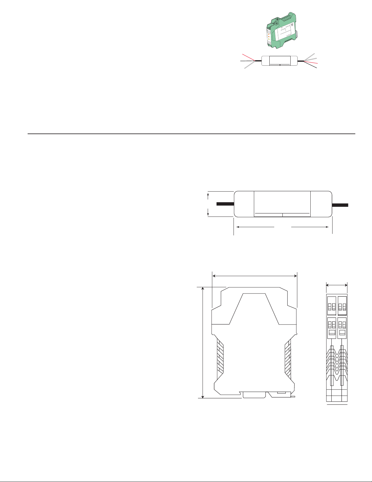
The 8058 Signal Converter accepts any 4 to 20 milliamp signal and converts it into the serial data format used by the Signet 8250,
8350, 8450 and 8900 instruments known as S
3
L. (Signet Serial Sensor Link)
• When used with the 8900 Multi-Parameter Controller, all programming uses the familiar 8900 setup menus.
• When used with ProcessPro transmitters, the 8058 is confi gured at the factory to the user's specifi cations.
• The 8058-1 wire-mount version is easily mounted anywhere in the interconnnecting wiring between a single 4-to-20 mA source and
the instrument.
• The 8058-2 DIN-rail mounted version converts two separate 4-to-20 mA source signals into the S3L format.
Specifi cations
Dimensions
General
Input: 4 to 20mA current loop(s), passive
(external power required)
Input range: 3.6 to 22.1 mA
Output: Digital (S
3
L) output
3-8058-1 Signal Converter, wire-mount
3-8058-2: calibrated mA
Accuracy: ±32 µA @ 25°C
Resolution: <16 µA
Update rate: 500 mS
Temp. Drift: ±1 µA per °C, max.
Electrical
Power req.: 4.5 to 6.5 VDC @ < 3.0 mA
16 mm
(0.63 in.)
4-to-20 mA
Input
+GF+
4-20 mA input S3L Output
4-20 mA to S
104mm
(4.1 in.)
Signet 8058 i-Go™
3
L Converter
L
3
S
Output
Max. voltage: 35 VDC
Max. current: 40 mA
Isolation: Up to 48 Volts AC/DC
Voltage drop: 5 VDC max.
Reverse polarity protected
99mm (3.90 in.)
Cable:
22.5mm
(0.89 in.)
3-8058-1: 400 mm (15 in.) input,
200 mm (8 in.) output
3-8058-2: No cable provided
(customer supplied)
Max. recommended cable extensions:
• Loop in: 300m (1000 ft.)
3
L out: per S3L guidelines
• S
Environmental
Operating Ambient Temperature:
-10°C to 55°C (14°F to 131°F)
Storage Temperature:
-20°C to 85°C (-4°F to 185°F)
Relative Humidity:
• 3-8058-1: 0 to 100%, condensing
• 3-8058-2: 0 to 90%, non-condensing
Shipping Weight:
• 3-8058-1: 0.12 kg (0.26 lb.)
• 3-8058-2: 0.15 kg (0.35 lb.)
Standards and Approvals
• CE
• Emissions and Immunity per EN 61326:
EN61000-6-2 Immunity
EN55011 Class B Emissions
114.5mm (4.51 in.)
3-8058-2 Signal Converter, DIN-rail mount
Page 2
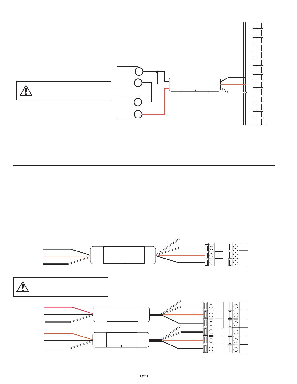
Wiring: 8058-1 Wire Mount to Signet 8900
Wiring Tips:
• Do not route sensor cable in conduit containing AC power wiring. Electrical noise may interfere with the signal.
• Routing cable in grounded metal conduit will help prevent electrical noise and mechanical damage.
• Seal cable splices tightly to prevent moisture damage.
• The cable length from the 8058 to the 8900 must not exceed the S
3
L limitations as defi ned in the 8900 instruction
manual.
Tie SHIELD to BLACK
CAUTION
Loop power must not exceed 35 VDC.
Loop Power
VDC
4 to 20 mA
Loop Source
+
+
BLACK (Loop -)
SHIELD
RED: (Loop +)
4-20 mA
Input
+GF+
Signet 8058 i-Go™
3
L Converter
4-20 mA to S
4-20 mA input S3L Output
BLACK (5 VDC)
L
RED (S3L)
3
S
Output
WHITE (GROUND)
Tie SHIELD to WHITE
-
1
2
3
4
5
6
7
8
9
10
11
12
13
14
8900 terminals
1. Wire the 8058 between the 4-20 mA loop source and the 8900 S3L input terminals as illustrated.
2. In the 8900 menu, assign a channel for this input, and specify the input parameter.
If the 4-20 mA SOURCE is one of the standard 8900 input parameters (fl ow, pH, Conductivity, etc.) select that channel type.
If the 4-20 mA SOURCE is not included in the 8900 menu, select OTHER (4-20) and then set additional labels and abbreviations
per the 8900 instructions.
3. Follow complete instructions in the 8900 manual to set up the new channel.
Wiring: 8058-1 Wire Mount to Signet 8250, 8350, and 8450 ProcessPro Transmitters
When used in conjunction with the Signet ProcessPro Pressure, Temperature or Level Transmitters, the 8058 serves to expand the
operating range beyond the specifi cations of sensors available directly from Signet.
1. Order the 8058 according to the instructions on page 4. The 8058 MUST be factory confi gured for these applications.
2. Connect the 8058 between the 4-20 mA loop source and the ProcessPro S
3. Follow the complete CALIBRATION instructions in the ProcessPro manual.
BLACK (5 VDC)
RED (S3L)
Shield
(Tie Shield to Black)
4-to-20 mA
+GF+
Input
4-20 mA input S3L Output
Signet 8058 i-Go™
4-20 mA to S3L Converter
Output
CAUTION
Loop power must not exceed 35 VDC.
RED (LOOP +)
BLACK (LOOP -)
SHIELD
(Tie Shield to Black)
RED (LOOP +)
BLACK (LOOP -)
SHIELD
(Tie Shield to Black)
4-to-20 mA
Input
4-to-20 mA
Input
+GF+
4-20 mA input S3L Output
+GF+
4-20 mA input S3L Output
4-20 mA to S
Signet 8058 i-Go™
4-20 mA to S
Signet 8058 i-Go™
3
L Converter
3
L Converter
L
3
S
Output
Tie Shield to White
L
3
S
Output
3
L input terminals as illustrated.
WHITE (GROUND)
Shield (Tie Shield to White)
L
3
S
Tie Shield to White
Shield
Shield
RED (S3L)
BLACK (5 VDC)
WHITE (GROUND)
RED (S3L)
BLACK (5 VDC)
WHITE (GROUND)
RED (S3L)
BLACK (5 VDC)
8350-1
8450-1
Terminals
7
6
5
8350-3
8450-3
Terminals
16
15
14
13
12
11
8250-2
8350-2
8450-2
Terminals
13
12
11
8250-3
Terminals
18
17
16
15
14
13
2 8058 i-Go™ Signal Converter
Page 3
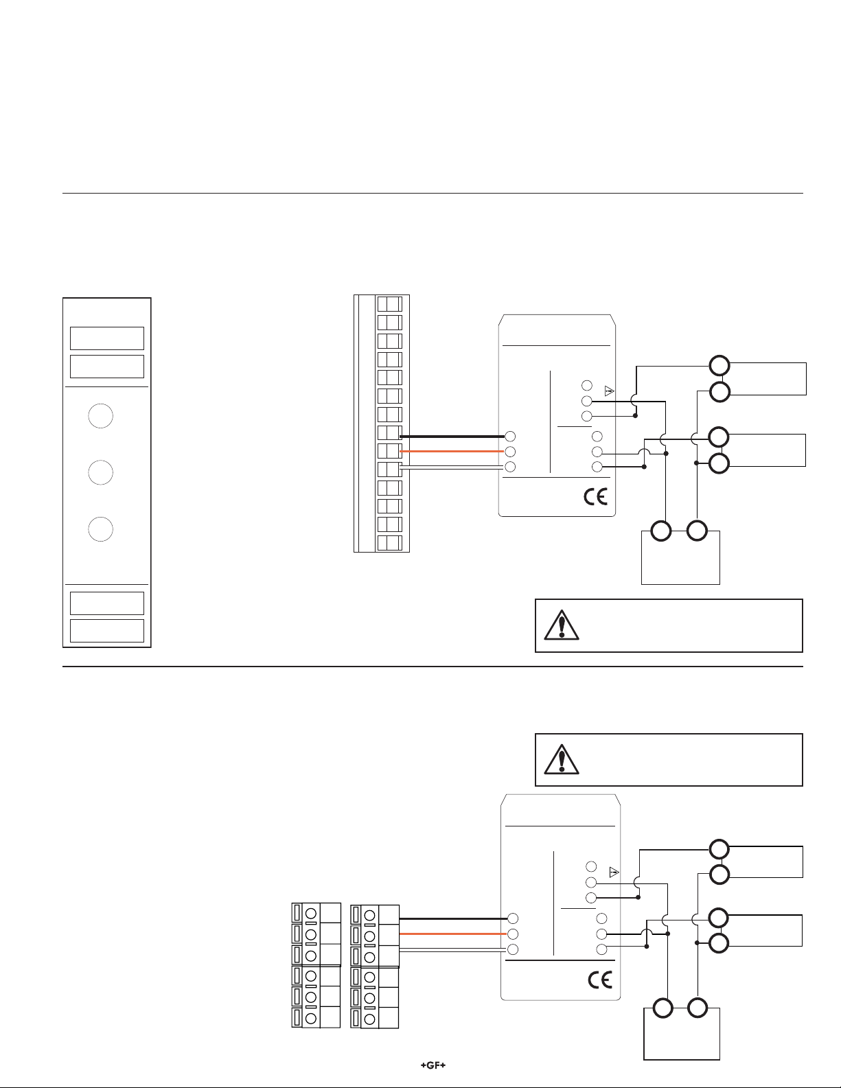
Wiring: 8058-2 DIN Rail Mount to Signet 8900 Multi-Parameter Controller
The 8058-2 accepts two 4 to 20 mA loop input signals and converts them into two S3L serial data signals for input to the Signet 8900,
where each loop is completely independent. The 8058 transmits information to identify the two signals by using the serial number of
the 8058 converter:
• The manufacture date of the 8058 is included in the serial number
label on the instrument.
• The 8058 converter transmits the serial number onto the S
3
L bus as
the id for the Loop 1.
• The 8058 transmits a second serial number for Loop 2 by by adding
12 to the month. (6040630.... becomes 6041830....)
1. Wire the 8058 between the 4-20 mA loop source and the 8900 S3L input terminals as illustrated.
2. In the 8900 menu, assign a channel for this input, and specify the input parameter.
If the 4-20 mA SOURCE is from one of the standard 8900 input parameters (fl ow, pH, Conductivity, etc.) select that channel type.
If the 4-20 mA SOURCE is a type not included in the 8900 menu, select "OTHER (4-20)" and then set additional labels,
abbreviations and units per the 8900 instructions.
1
+GF+
3 2 1
6 5 4
Loop1
PWR
Loop2
PWR
S L
DATA
Two 4-20 mA loop signals can
be connected to the 8058-2.
·The red Loop LEDs indicate
when one or both of the 4 to 20
mA loop inputs are powered.
3
·The green DATA LED
indicates when the data
2
3
4
5
6
7
8
9
10
11
12
13
14
BLACK (5 VDC)
RED (S3L)
WHITE (GROUND)
output is active.
Signet 8058
N/C
7 8 9
3
The S
L output terminals carry
the input loop signals to the
8900.
8900 terminals
Loop 1: 6 04 06 30 1234
Loop 2: 6 04 18 30 1234
Signet 8058 i-Go™
+GF+
4-20mA to S
3
S L
Output
7 +5VDC
3
8 S L
9 GND
3-8058.610D
3
L Converter
4-20 mA
Input
N/C 6
Loop2 - 5
Loop2+ 4
N/C 3
Loop1 - 2
Loop1 + 1
X
X
Year
mfg
35VDC MAX
Month
mfg
-
+
Power
Supply
12-24 VDC
Day
SequentialDisregard
mfg
-
4-20 mA Loop 2
Source
+
-
4-20 mA Loop 1
+
Source
CAUTION
Loop power must not exceed 35 VDC.
Wiring: 8058-2 DIN Rail Mount to Signet 8250, 8350, and 8450 ProcessPro Transmitters
When using the 8058-2 with the Signet 8250-3, 8350-3 or 8450-3, both loop sources must be of the same TYPE, and the 8058-2 MUST
be factory-confi gured to the correct range.
CAUTION
1. Order the 8058-2 according to the instructions on page 4.
The 8058 MUST be factory confi gured for these applications.
2. Connect the 8058 between the 4-20 mA loop source and the
ProcessPro S
3
L input terminals as illustrated.
3. Follow the complete CALIBRATION instructions in the
ProcessPro manual.
8350-3
8450-3
Terminals
16
15
14
13
12
11
8250-3
Terminals
18
17
16
15
14
13
BLACK (5 VDC)
RED (S3L)
WHITE (GROUND)
Signet 8058 i-Go™
+GF+
4-20mA to S
3
S L
Output
7 +5VDC
3
8 S L
9 GND
3-8058.610D
Loop power must not exceed 35 VDC.
3
L Converter
4-20 mA
Input
N/C 6
Loop2 - 5
Loop2+ 4
N/C 3
Loop1 - 2
Loop1 + 1
35VDC MAX
-
Power Supply
12 - 24 VDC
+
+
+
4 - 20 mA
Loop 2 Source
4 - 20 mA
Loop 1 Source
3 8058 i-Go™ Signal Converter
Page 4
IMPORTANT! SPECIAL INFORMATION for ProcessPro Users:
The following information is REQUIRED with all converters that will be connected to:
Signet 8250 Level Transmitter
Signet 8350 Temperature Transmitter
Signet 8250 Level Transmitter
1. Select the 8058 model preferred:
3
______ 3-8058-1S Wire-mount current to S
______ 3-8058-2S DIN rail mount current to S3L converter, dual input (for use with 8250-3, 8350-3 or 8450-3 Transmitters)
2. Specify the Signet ProcessPro model to be connected to the 8058:
______ 8250 Level Transmitter ______ 8350 Temperature Transmitter ______ 8450 Pressure Transmitter
3. Specify the operating range and engineering units from the input 4-20 mA loop source:
Loop 1: 4 mA = _______________(specify units) 20 mA = _______________(specify units)
Loop 2 (-3 models only): 4 mA = _______________(specify units) 20 mA = _______________(specify units)
Note: For dual-loop systems, both input loops must be the same parameter, but the ranges may be different.
L converter (for use with 8250, 8350 or 8450 -1 or -2 model Transmitters).
4. Contact a Signet representative
Due to the customization requirements, the 8058 Converter requires special handling when intended for use with ProcessPro
transmitters. Consult with Signet product specialist for these requirements.
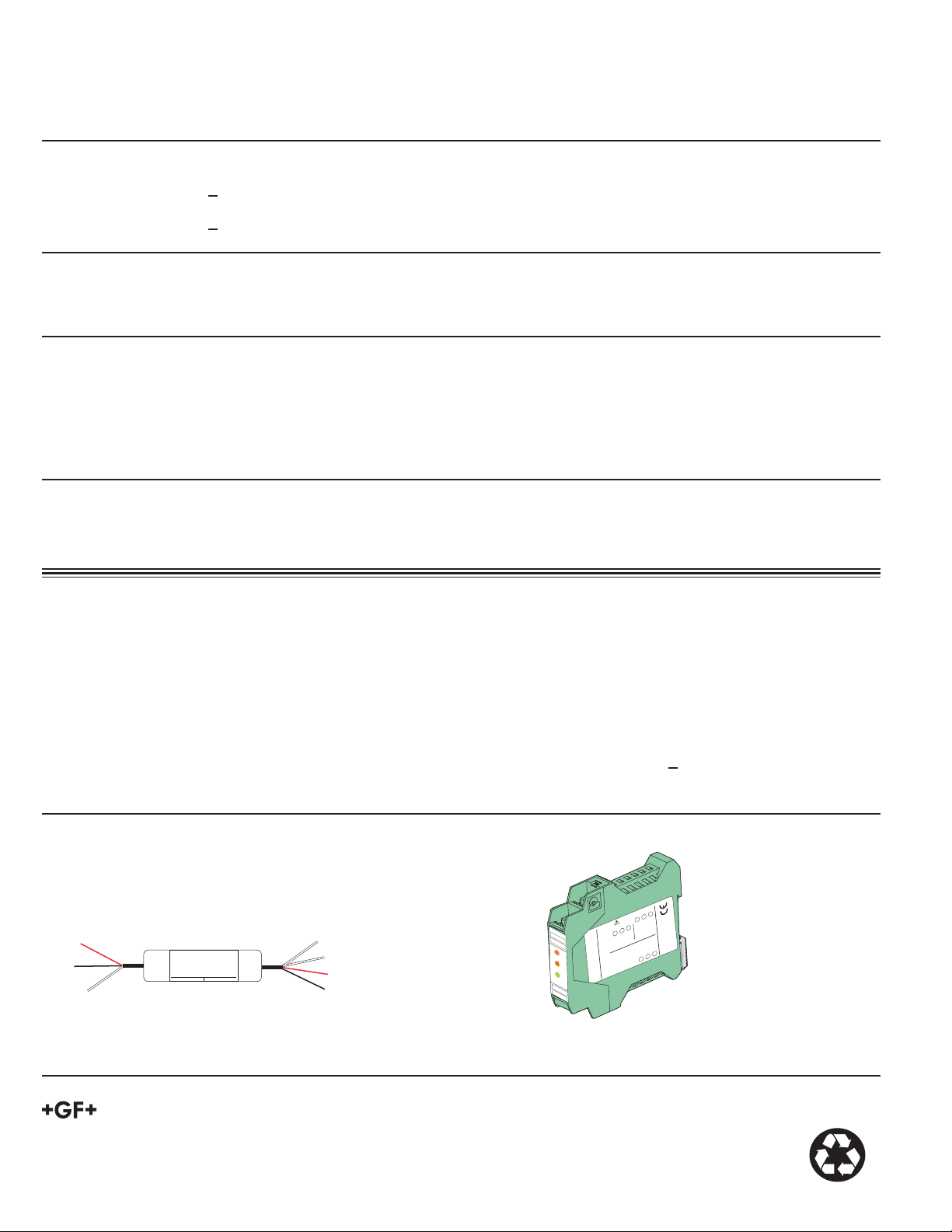
Ordering Information
Mfr. Part No. Code Description
3-8058-1 159 000 966 Wire-mount current to S3L converter for use with Signet 8900
3-8058-2 159 000 967 DIN rail mount current to S3L converter, dual input for use with Signet 8900
NOTE: If the 8058 converter is to be used with any 8250, 8350 or 8450 ProcessPro Transmitter, add S to the order number, complete
the information noted above, and contact your Signet representative.
5VDC MAX
3
Loop1 + 1
4-20 mA
3
S L
Loop1 - 2
N/C 3
Loop2+ 4
Loop2 - 5
Input
N/C 6
C
3-8058.610D
3
9 GND
8 S L
7 +5VD
Output
+GF+
3 2 1
Red
Black
Shield
(Tie to Black)
4-to-20 mA
Input
+GF+
Signet 8058 i-Go™
4-20 mA to S
4-20 mA input S3L Output
3
L Converter
Output
Shield
(Tie to White)
L
3
White (Ground)
S
Red
Black
6 5 4
Loop1
L Converter
3
PWR
Loop2
PWR
4-20mA to S
8058 i-Go™
S L
3
DATA
+GF+
Sign
et 8058
N/C
7 8 9
3-8058-1 Wire-mount Current-to-S3L Converter
3-8058-2 DIN-mount Current-to-S3L Converter
George Fischer Signet Inc., 3401 Aerojet Avenue, El Monte, CA 91731-2882 U.S.A. • Tel. (626) 571-2770 • Fax (626) 573-2057
For Worldwide Sales and Service, visit our website: www.gfsignet.com • Or call (in the U.S.): (800) 854-4090
3-8058.090 Rev. B 8/05 English © George Fischer Signet 2004 Printed in U.S.A. on recycled paper
 Loading...