

Page 1
Signet 5600 Batch Controller
English
*3-5600.090-1*
3-5600.090-1 (Rev. E-8/04) English
Contents
1. Wiring terminals
2. Power Connection
3. Compatible Sensor Wiring
4. Batch Contact Wiring
5. Remote Control Wiring
6. End of Batch/Counter Pulse Output Wiring
7. Option Contact Wiring Options
8. Current Output Wiring Options
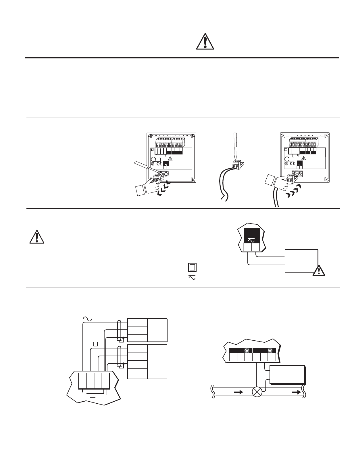
1. Wiring terminals
• Remove terminal blocks for easy wiring.
CAUTION!
• Remove power to unit before wiring input and
output connections.
• Follow instructions carefully to avoid personal
injury.
9. 5600 Operation Modes
10. Menu Functions
11. Parts and Accessories
12. Specifi cations
13. Quick Reference Menu Parameters
14. Maintenance
15. Troubleshooting
1.
1 2 3 4 5 6
1 2 3 4
2
+
1
Gnd
+
Gnd
Total
AUX
Std. Sensor
U
PLS
Freq. IN
Freq. IN
Iso. Gnd
Sen. Pwr.
output
output
Open Collector
Sensor
LISTED
L
77CJ
12-24 V
10 W
+
-
1 2
Flow
reset
Patent No. D376,328
2.
1 2
3.
1 2 3 4 5 6
1 2 3 4
2
+
1
Gnd
+
Gnd
Total
AUX
Std. Sensor
U
PLS
Freq. IN
Freq. IN
Iso. Gnd
Sen. Pwr.
output
output
Open Collector
Sensor
LISTED
L
77CJ
12-24 V
10 W
+
-
1 2
Flow
reset
Patent No. D376,328
2. Power Connection
CAUTION!
Never connect 115 VAC or 230 VAC to rear power
terminals. High voltage AC will damage instrument and
void warranty.
Technical Notes:
• Maximum 4-20 mA loop impedance (sec. 8A) is affected by the
supply voltage.
• To reduce the possibility of noise interference, isolate AC power
lines from signal lines.
3. Compatible Sensor Wiring
Signet Sensors:
Std. Sensor
Freq. IN
Freq. IN
Iso. Gnd
Sen. Pwr.
Open Collector
Sensor
Red
Black
Shld.
Red
Black
Shld.
5600
Terminals
515
525
2517
2000
2507
2536
2540
2550
Vortex*
5600
12-24 V
10 W
Terminals
External power
+
-
supply
-
12 - 24 VDC
OR
= Double Insulated
12 - 24 VAC
+
= DC or AC power
4. Batch Contact Wiring
See section 9 for simple and advanced mode confi guration
options.
5600
Option
NO
Batch
C
NC
NO
C
Terminals
NC
AC or DC
power
flow
valve
Technical Notes:
• To reduce the possibility of noise interference, route sensor
cable )away from AC power lines.
• *Vortex sensor or system frequency output
Technical Notes:
• Maximum alarm contact ratings: 5 A @ 30 VDC, 5 A @ 125
VAC, or 3 A @ 250 VAC
• To reduce the possibility of noise interference, isolate AC power
lines from signal lines.
Page 2
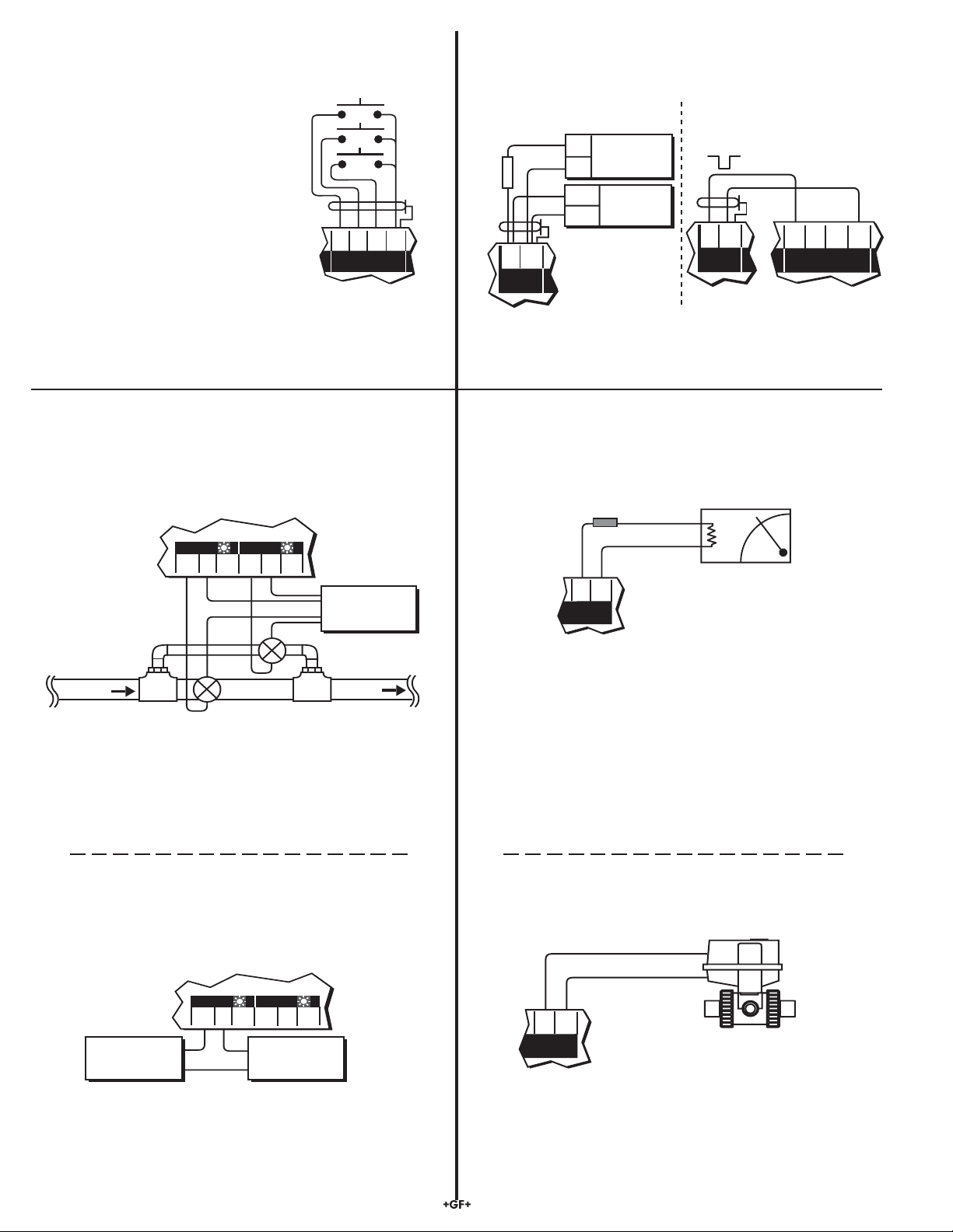
5. Remote Control Wiring
Rear START, STOP, and RESUME
(Rsm) terminals can provide remote
batch control from a distance using
one of four methods:
• Mechanical switch closures (shown)
• End of batch pulse from a second
5600 (sec. 6)
• End of batch contact closure from a
second 5600 (sec. 7C).
• End of batch current pulse from a
second 5600 (sec. 8C).
Momentary Switch Contacts
(customer supplied)
5600
Terminals
Start
Stop
Remote
Rsm
Start
Stop
Resume
RTN
6. End of Batch/Counter Pulse Output Wiring
See section 9 for simple and advanced mode confi guration options.
A. External counter connection
+
5 - 30
VDC
Gnd
-
IN
Gnd
5600
External
Counter
10 kΩ
+
CNT/EOB
output
Terminals
B. Daisy chaining two 5600
batch controllers together
+
Gnd
CNT/EOB
output
First 5600
Stop
Start
Remote
Second 5600
Rsm
RTN
Technical Notes:
• Use 4-conductor shielded cable for remote control lines up to
30 m (100 ft) max.
7. Option Contact Wiring Options
A. Two Stage Shutdown (advanced mode only, sec. 9.2)
5600
Terminals
NC
AC or DC
power
to tank
NC
Val ve
NO
Batch
C
Main line
flow
Bypass line
Option
NO
C
Technical Notes:
• Maximum alarm contact ratings: 5 A @ 30 VDC, 5 A @ 125
VAC, or 3 A @ 250 VAC
• To reduce the possibility of noise interference, isolate AC power
lines from signal lines.
Technical Notes:
• Use 2-conductor shielded twisted-pair cable for output lines
up to 30 m (100 ft.) max.
8. Current Output Wiring Options
A. Batch Completion (simple or advanced mode, sec. 9)
Fuse**
1/8A
+
4 - 20 mA
*
-
+
Current
output
Technical Notes:
**1/8A fuse recommended (customer supplied)
* 4-20 mA output is internally powered (non-isolated),
maximum loop impedance 350 Ω with a 12 V instrument supply
voltage, 950 Ω with a 24 V instrument supply voltage.
To isolate output and prevent ground loop problems:
1. Use monitor device with isolated inputs, or
2. Use separate DC supply for 5600 and monitor device, or
3. Power 5600 with 12 - 24 VAC step down transformer
-
5600
Terminals
B. Missing Signal Alarm (simple or advanced mode, sec. 9)
OR Overrun Alarm (advanced mode only, sec. 9.2)
5600
Terminals
Alarm
device
Option
NO
C
NC
Batch
NO
AC or DC
C
power
NC
Technical Notes:
• Maximum alarm contact ratings: 5 A @ 30 VDC, 5 A @ 125
VAC, or 3 A @ 250 VAC
• To reduce the possibility of noise interference, isolate AC power
lines from signal lines.
2 of 12
B. Valve Control (advanced mode only, sec. 9.2)
#5 ( + )
4 - 20 mA
#6 ( - )
-
5600
Terminals
George Fischer electronic
actuator with PE 22P
positioner required
+
Current
output
Technical Notes:
• Output compatible with the following George Fischer electronic
actuators/PE 22P positioner models: EA 20, EA 30, EA 41
and EA 50
Signet 5600 Batch Controller
Page 3
Section 7 Continued...
Section 8 Continued...
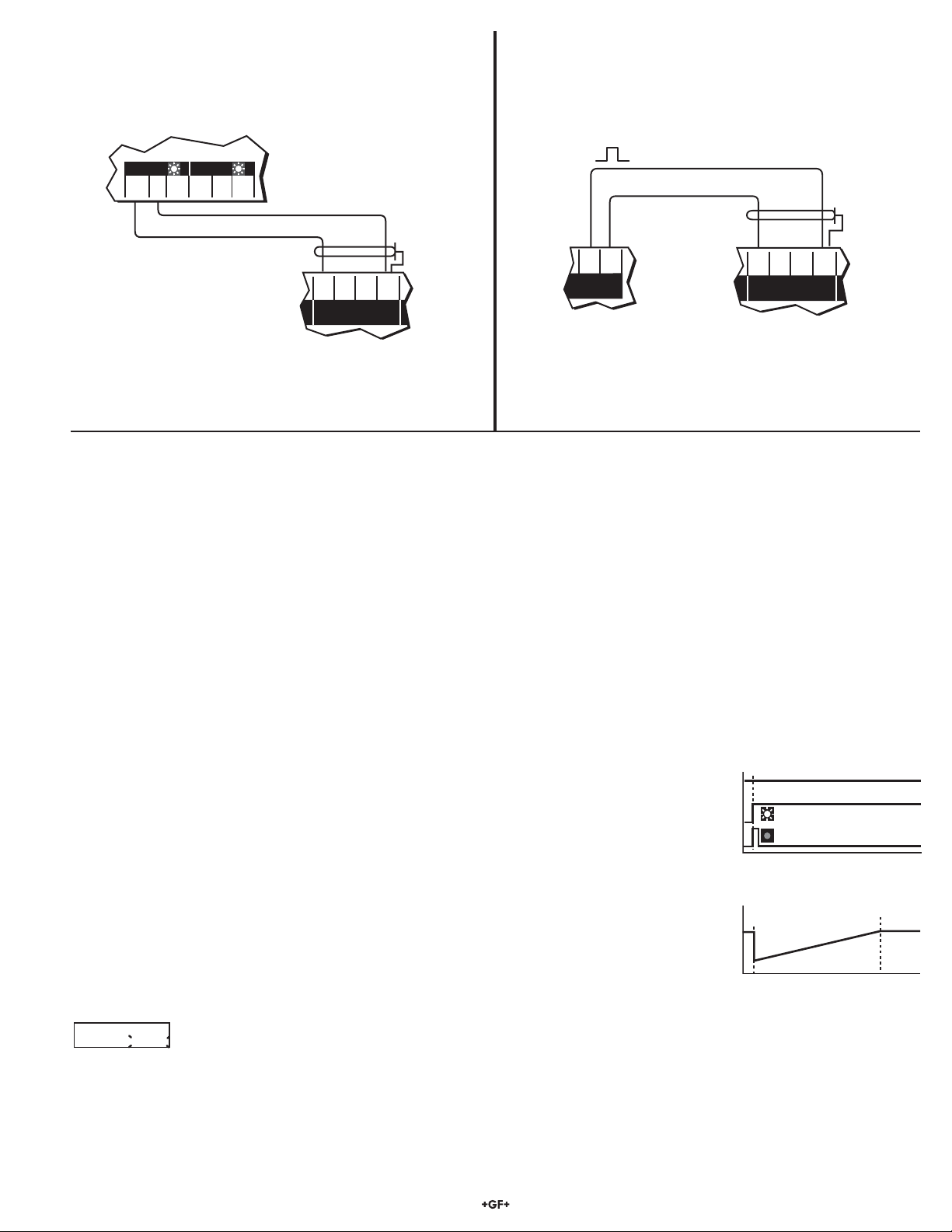
C. End of Batch Pulse (advanced mode only, sec. 9.2)
Daisy chaining two 5600 batch controllers together for a second
batching stage.
C. End of Batch Pulse (advanced mode only, sec. 9.2)
Daisy chaining two 5600 batch controllers together for a second
batching stage.
5600
NC
NO
Batch
C
Option
NO
C
First 5600
Technical Notes:
• Use 2-conductor shielded twisted-pair cable for contact lines
up to 30 m (100 ft.) max.
NC
Second
5600
Terminals
Start
Remote
Stop
Rsm
RTN
-
5600
Terminals
Rsm
Stop
Start
Remote
Second 5600
RTN
+
Current
output
First 5600
Technical Notes:
• Wiring MUST be connected exactly as shown.
• Use 2-conductor shielded twisted-pair cable for output lines
up to 30 m (100 ft) max.
9. 5600 Operation Modes
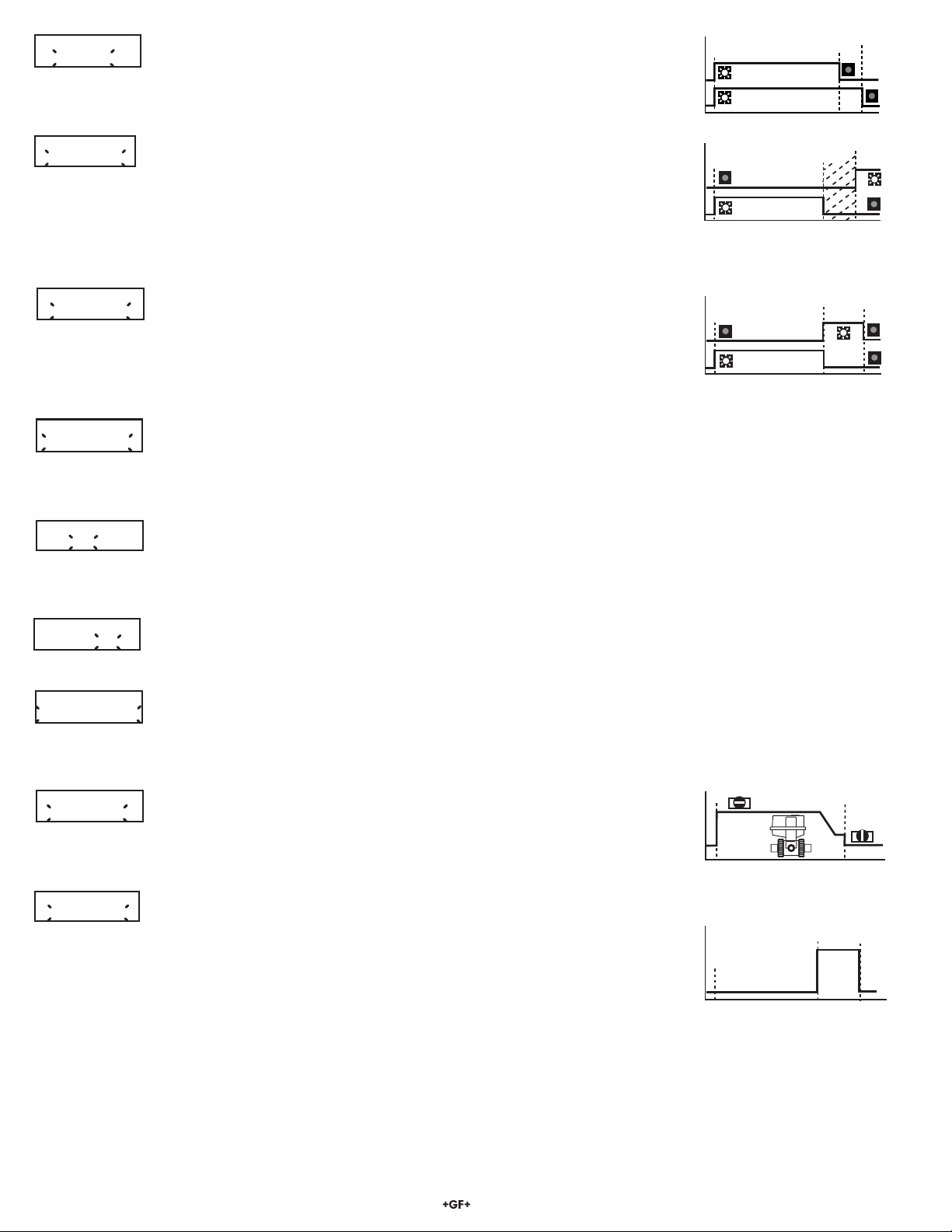
This section gives a detailed description of the 5600's simple and advanced operation modes (sec. 14) and how they affect the batch contact, End of batch/totalizer output, option contact, and current output.
9.1 Simple Operation Mode
• Batch Contact (sec. 4): In simple mode, the batch contact is dedicated for on/off control. It is energized at the start of a batch and
de-energized at the end of a batch. It also de-energizes when STOP is selected from the front keypad or initiated by a remote contact
closure to the rear STOP terminals (sec. 5). A RESUME command can also be initiated by either method to complete the batch. The
front panel batch indicator turns on when the batch contact is energized.
• Counter/End of Batch Pulse Output (sec. 6): In simple mode, the output is confi gured as a counter pulse output. The output emits a
130 millisecond pulse for each engineering (total) unit measured. The output is a open collector type which requires an external pull up
resistor and power supply for external counter use (sec. 6).
• Option Contact - Missing Signal Alarm (sec. 7B): This function provides alarm capability if fl ow is not detected in 30 seconds after
a batch cycle starts. If the fl ow sensor signal is missing, the option contact energizes and the front panel
contact indicator turns on, signaling the missing sensor signal. The batch contact also
de-energizes, closing the fl ow control valve and stopping the batch. The alarm condition will remain until the
front panel ENTER key is pressed or a remote contact closure is made to the rear STOP terminal (sec. 5).
• Current Output - Batch Completion (sec. 8A): This function is offered in the simple or advanced operation mode. The output is a linear increase from 4 mA at batch start to 20 mA at batch end.
9.2 Advanced Operation Mode
• Batch Contact (sec. 4): The batch contact is dedicated for on/off control and is either manually or auto-
matically
compensated for batch overrun. Manual overrun compensation allows the operator to compensate for valve closure time in a batching
Overrun Comp:
automatic manual
based on the additional sensor pulses, then automatically reduces the next batch size for the next batch. During the next batch cycle, the
batch contact de-energizes early, thus closing the fl ow control valve early and eliminating batch overrun.
system. The operator is prompted to enter a batch volume that de-energizes the batch contact early, compensating
for valve closing time and eliminating batch overrun. Automatic overrun compensation counts sensor pulses during
the batch cycle, and any excess pulses after the batch stops. The instrument calculates the estimated batch overrun
Batch started...
Sensor input
option contact
batch contact
Batch running...
0%
4 mA
100%
20 mA
Signet 5600 Batch Controller
3 of 12
Page 4
Option Contact:
Two Stage
• Counter/End of Batch Pulse Output (sec. 6): In advanced mode, the output can
be confi gured as either a counter pulse output (sec. 9.1) or as an end of batch pulse
output. When confi gured as an end of batch pulse, the output emits a 500 millisecond
pulse at the completion of every batch. The output is a open collector type which requires an external pull
up resistor and power supply for external counter use (sec. 6).
Batch running...
0%
Option contact
batch contact
90%
100%
Option Contact:
Overrun Alarm
• Option Contact - Two Stage Shutdown (sec. 7A): This function is designed to pre-
vent over fi lling or to minimize water hammer. Both the batch and the option contact
are energized when the batch starts. The option contact then de-energizes at
a programmed batch percentage, forcing fl ow through a smaller bypass line to reduce the fi ll rate. After
the entire batch is measured, the batch contact de-energizes, completing the sequence. Front keypad
and remote START, STOP, and RESUME inputs (sec. 5) also control the option contact. The front panel
contact indicator turns on when the option contact is energized.
Option Contact:
End of Batch
• Option Contact - Overrun Alarm (sec. 7B): This function provides overrun alarm
capability for detecting a leaky or stuck valve. If the programmed batch overrun
volume is measured after the batch ends, the option contact is energized and the front
panel contact indicator turns on, alarming the operator that the fl ow shut off valve is leaking or stuck open.
To cancel alarm, press the ENTER key (or remote STOP switch) once. The overrun alarm will retrigger if
the condition persists.
Option Contact:
Missing Signal
• Option Contact - End of Batch Pulse (sec. 7C): This function is designed to trigger an external batch counter or
second 5600 Batch Controller at the end of a batch. The option contact is energized for 500 milliseconds at the end
of every batch cycle. An external power supply switched through the option contact's common (COM) and normally
open (NO) terminal provides a pulse for triggering these devices.
Option Contact:
Off
• Option Contact - Missing Signal Alarm (sec. 7B): The missing signal alarm represents a missing sensor signal
after batch start-up. An adjustable time delay entry (in seconds) is offered which specifi es how long the instrument
will wait after batch start-up before initiating the missing signal alarm. See simple operation mode (sec. 9.1) for alarm
operation details.
Batch running...
0%
Option contact
batch contact
Batch running...
0%
Option contact
batch contact
100%
100%
Overrun
500ms
Missing Signal
Alarm: On
Current Output:
Batch Completion
• Option Contact On/Off (sec. 10.4H): This function enables or disables the option contact and front panel option
LED. When the option contact is confi gured "Off", the option contact and front panel LED are disabled.
• Missing Signal Alarm On/Off (sec. 10.4H):
Missing signal alarm is always enabled (factory default sec. 9.1) even if the option contact is selected to be a different
function. This function is designed to completely disable the missing signal alarm, if desired. NOTE: If disabled, the
batch contact is NOT affected and will NOT signal the operator or stop the running batch if there is a problem.
Current Output:
Valve Control
Current Output:
End of Batch
• Current Output - Batch Completion (sec. 8A): In advanced mode, the current
output functions identical to the simple operation mode. See the simple operation mode
explanation above.
• Current Output - Valve Control (sec. 8B): This function is designed for use with a George Fischer electric actuator with PE 22P positioner for preventing overfl ow or minimizing water hammer. When a batch starts, the current
output is held at 20 mA, forcing the PE 22P positioner to the full open valve position.
Near batch end, the output gradually ramps downward to slow the fl owrate, then drops to 4 mA closing the
valve and ending the batch. Front keypad and remote START, STOP, and RESUME inputs also control
the output (sec. 5). A STOP command any time during a batch sequence will force the output to 4 mA and
close the PE 22P positioner. (Note: for optimum performance, the batch process should last at least 1
minute!)
Batch running...
0%
valve
20 mA
4 mA
Batch running...
0%
0 mA
100%
valve
100%
20 mA
500ms
4 of 12
Signet 5600 Batch Controller
Page 5
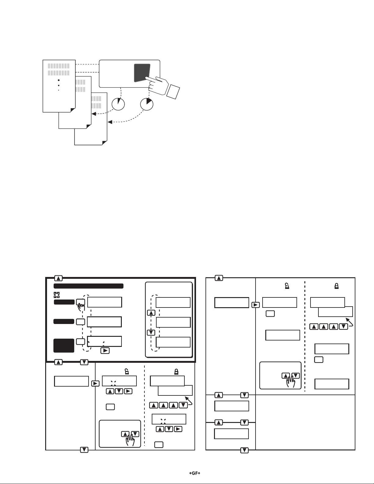
10. Menu Functions
*Note: BATCH/VIEW Menu steps B - E MUST be selected for
CALIBRATE Menu (sec. 10.2) or OPTIONS Menu (sec. 10.4) access.
Press &
hold for
ENTER
access:
VIEW
2s 5s
CALIBRATE
OPTIONS
Menus:
• BATCH/VIEW menu (sec. 10.1): The BATCH/VIEW menu is
displayed during standard operation. The ENTER key controls
batch start, batch stop, and batch resume operations. While a
batch is not running, the operator can navigate freely through
the menu by pressing either UP or DOWN arrow keys. While
a batch is running, pressing either UP or DOWN arrow keys
displays Time left, Flow rate, and Volume batched information.
The BATCH/VIEW menu also offers a programmable batch
size and resettable totalizer feature that allows the operator to
reset the displayed total at the press of a button.
• CALIBRATE Menu (sec. 10.2): The CALIBRATE menu
contains all critical display setup and output parameters. A
simple security code feature prevents unauthorized tampering.
The operator is required to enter a simple access code for
menu access. The same code also unlocks OPTIONS menus.
• OPTIONS Menu (sec. 10.4): The OPTIONS menu contains
setup and display features that are seldom accessed for minor
display or output adjustments.
10.1 BATCH/VIEW Menu (example)
• Menu steps B - E cannot be accessed when a batch is running. Press ENTER to stop batch cycle.
• Steps B - E MUST be selected for CALIBRATE Menu (sec. 10.2) or OPTIONS Menu (sec. 10.4) access.
To Step E →
Batch
Start
A
.
Stop
Resume
or
start
Batch Volume:
B
.
100.000 Gallons>
Programmable
Batch Volume
Main Batching Sequence
0.0 Gallons
ENTER
<ENTER> to Start
40.3 Gallons
ENTER
<ENTER> to Stop
Volume batched
40.3 Gallons
ENTER
Resume Start
Resume or start
(sec. 10.4D)
OPTIONS =
Batch Volume:
200.500 Gallons
1. Enter volume
ENTER
2.
O
R
To exit without
changes:
Save
quick
press
Count Up
selected
(sec.10.4K)
While a batch
is running...
Time Left: <1 min
<ENTER> to Stop
Time Left
60.5 Gallons/m
<ENTER> to Stop
Flow rate
40.3 Gallons
<ENTER> to Stop
Volume batched
(sec. 10.4D)
OPTIONS =
Batch Volume:
Key Code: -- -- -- --
Batch Volume:
Key Code:
1. Enter code:
Batch Volume:
200.500 Gallons
2. Enter volume
ENTER
Save
3.
****
← Back to Step B
Gallons X 1
C
.
Total:1234567.8>
Resettable Totalizer
D
.
Permanent Total
Overrun: Manual
E
.
0.00000 Gallons
Overrun compensation
(sec. 10.4D)
OPTIONS =
Reset Total?
1234567.8
ENTER
Press to reset
1.
Reset Total?
2.
0000000.0
O
R
To exit without
changes:
quick
press
D. Permanent Total cannot be reset.
E. Shown only when "advanced" mode is chosen
(sec. 10.4E)
(sec. 10.4D)
OPTIONS =
Reset Total?
Key Code: -- -- -- --
Reset Total?
Key Code:
1. Enter code:
Reset Total?:
1234567.8
ENTER
Press to reset
2.
Reset Total?:
3.
0000000.0
****
To step C →
Signet 5600 Batch Controller
← To step A)
5 of 12
Page 6
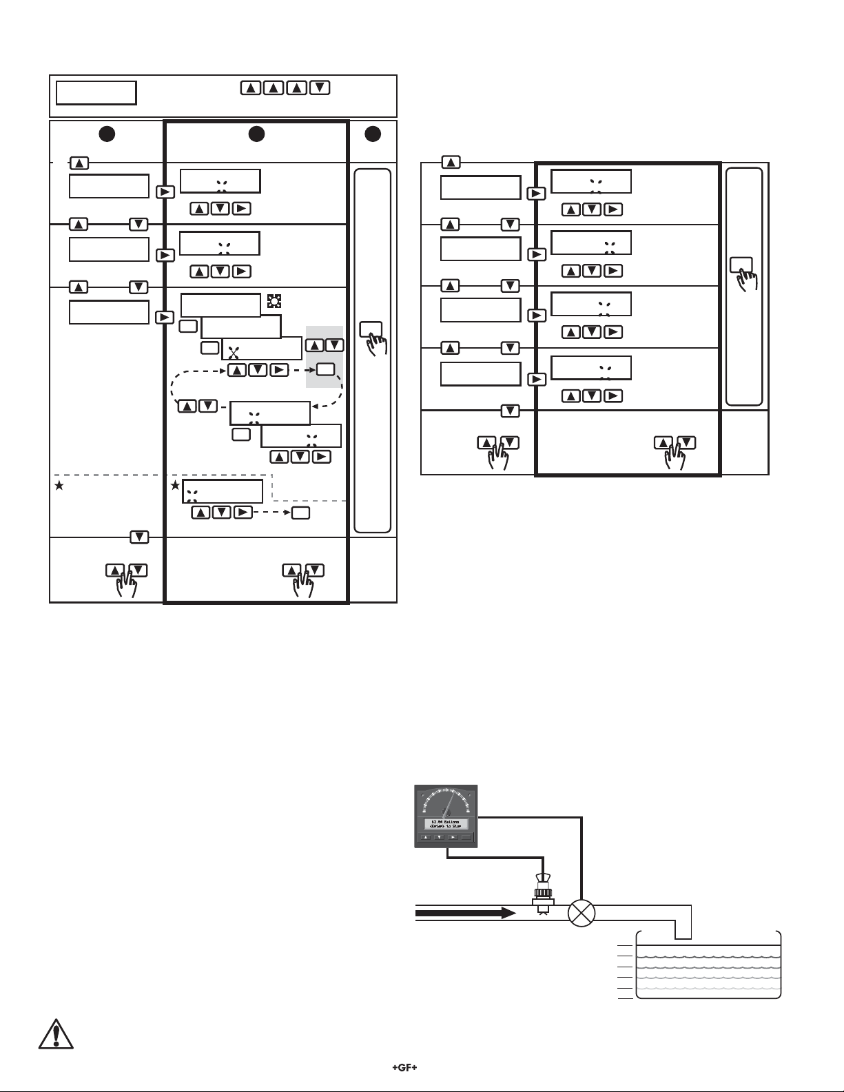
10.2 CALIBRATE Menu (factory defaults shown in menu column 1)
CALIBRATE: -- -- -- -Enter Key Code
Press keys in sequence to continue,
****
1
Choose:
G↓
Batch Units:
A.
Gallons >
Batch units
Flow Timebase:
B
.
m >
Flow timebase
Auto Calibrate:
C
.
Batch K-Factor >
Auto Calibrate
Procedure
Accurate reference
container required.
See procedure
(sec. 10.3)
Display shown only
when advanced mode
(sec.10.4E) and manual
overrun comp. (sec.10.4G)
is selected.
To return
to VIEW:
To step D →
quick
press
will appear during code entry.
2
Change:
Batch Units:
Liter
Flow Time Base:
s S m M h H d D
Auto Calibrate:
<ENTER> to Start
Auto Calibrate:
ENTER
<ENTER> to Stop
Start
Reenter
volume?
D. Overrun comp.
To restore original value:
Auto Cal Volume:
ENTER
XX.XXX Gallons
Stop
A.
K-Factor?
Overrun Volume:
XX.XXX Gallons
Set batch units:
Aa - Zz, 0 - 9,
/, _
Set timebase:
S=seconds,
M=minutes,
H=Hours,
D=Days
Enter volume
Batch K-Factor:
1234.5
Batch K-Factor
ENTER
1234.3
B.
Accept
Batch
Cancel
C.
Modify
K-Factor?
ENTER
S
ave
OR
ENTER
Save
quick
press
3
Save:
ENTER
"SAVING
briefly
display
←Back to step C
Batch K-Factor:
D
.
60.000 >
Batch K-Factor
Total Units:
E
.
Gallons x 1 >
Totalizer units
Total K-Factor:
F
.
60.000 >
Totalizer K-Factor
"
s
Last CAL:
G
.
01-01-98
Last calibration
To return
to VIEW:
←To step A
quick
press
*Note: Batch and totalizer K-Factor settings represent the number
of pulses generated by the
Batch K-Factor:
3456.7
Total Units:
Liters X100
Total K-Factor:
3456.7
Last CAL:
01-01-98
To restore original value:
+GF+
SIGNET fl ow sensor for each
Set batch
K-Factor:
0.0001 - 99999.
(see note*)
Set totalizer
units: Az - Zz,
0 - 9, /, _
(Label use only)
Set totalizer
K-Factor:
0.0001 - 99999.
(see note*)
Last CAL: Sets user
defined date
quick
press
engineering unit of fl uid measured (published in the fl ow sensor
manual).
ENTER
"SAVING"
briefly
displays
10.3 Auto Calibration Procedure
The auto calibrate procedure (sec. 10.2C) calculates a custom fl ow sensor/batch K-Factor based on volumetric measurement for more
precise batching. This process will compensate for installation abnormalities or nonstandard pipe sizes for maximum batch accuracy. An
accurate measurement reference container (e.g. known tank volume) is required for this procedure. If auto calibration is impractical for
your batch system, perform manual calibration using the K-Factors published in your fl ow sensor manual.
Requirements:
A. The fl ow sensor must be installed in the actual batch pipeline.
B. The fl ow control valve can be connected to the common (C)
and normally open (NO) batch contact terminals (sec. 4) or
the current output terminals (sec. 8B).
C. Either the batch contact or current output MUST be used to
energize and de-energize the main fl ow control valve which
starts and stops fl uid fl ow into the known reference container.
D. Follow the steps outlined in the auto calibration procedure
(sec.10.2C) to obtain your batch system's custom K-Factor.
WARNING!
The auto calibration procedure generates a custom batch K-Factor. The batch and Totalizer K-Factors are independent from
one another. ALWAYS reenter your totalizer K-Factor after performing the auto calibration procedure.
6 of 12
5600
60
40
Batch Option
80
20
Batch %
100
0
+GF+ SIGNET
Batch contact terminals (sec. 4) OR
4-20 mA valve control terminals (sec. 8B)
ENTER
Flow Sensor
Flow control valve
100
80
60
40
20
0
Signet 5600 Batch Controller
Reference Container
Page 7
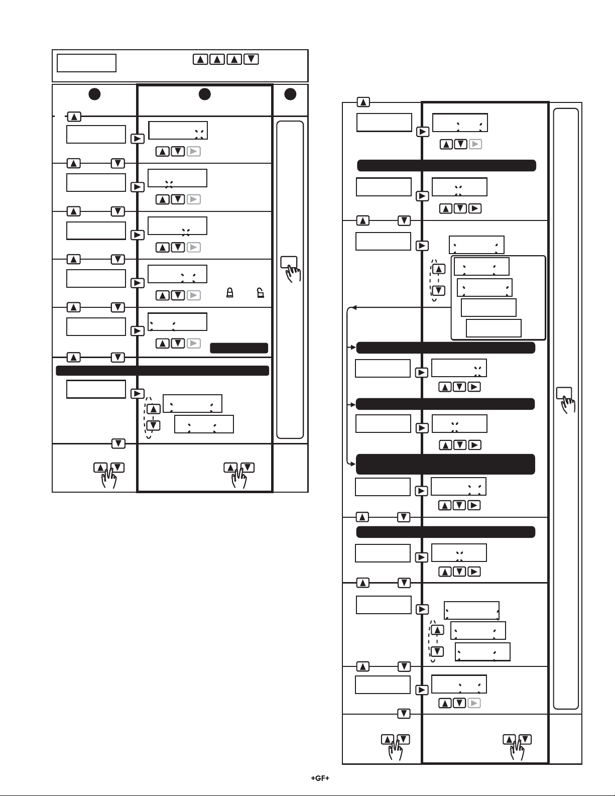
10.4 OPTIONS Menu (factory defaults shown in menu column 1)
OPTIONS: -- -- -- -Enter Key Code
1
Choose:
K↓
Contrast:
A.
3 >
Contrast
Display Decimal:
B.
C.
D.
E.
F.
To return
to VIEW:
>
*****.*
Flow decimal
Total Decimal:
.
>
*******
*
Totalizer decimal
Lock:
OFF >
VIEW Menu Lock
Operating Mode:
Advanced >
Operation mode
Pulse Output:
Totalizer >
Pulse Output
To step G→
Press keys in sequence to continue,
will appear during code entry.
****
2
Change:
Contrast:
1 2 3 4 5
Display Decimal:
.
****
**
Total Decimal:
******. **
Lock:
Off On
Operating Mode:
Simple Advanced
Advanced mode selected (step E)
Set pulse output (sec. 9.2):
Pulse Output:
End of Batch
Pulse Output:
Totalizer
To restore original value:
quick
press
Set contrast:
5 levels
Set flow decimal:
. -
******
**.****
Set totalizer
decimal:
. -
********
******.**
Set VIEW Menu
lock:
On= Off=
Set operation
mode:
Simple or
Advanced F - H
End of Batch
(EOB)
Totalizer
(CNT)
quick
press
3
Save:
ENTER
"SAVING"
briefly
displays
←Back to step F
Overrun Comp:
G.
Manual >
Batch contact
M
anual overru
Overrun Volume:
0.00000 Gallons>
Batch contact
Option Contact:
H.
Missing Signal >
Option contact
Two Stage
Setpoint%: 95.0>
Option Contact
Overrun Alarm mode selected
Overrun Alarm:
1.00000 Gallons>
Option Contact
Two Stage, Overrun Alarm, End of Batch, or Off
Missing Signal
Alarm: On >
Option Contact
Overrun Comp:
Auto Manual
n com
p selecte
Overrun Volume:
0003.75 Gallons
Set operation mode (sec. 9.2):
Two Stage mode selected
Two Stage
Setpoint%: 99.5
Overrun Alarm:
0002.50 Gallons
mode selected
Missing Signal
Alarm: Off On
Set overrun
compensation:
automatic
or manual
(sec. 9.2)
d
(
ste
p
G)
Set overrun
volume:
0.00000 -
999999.
Option Contact:
Missing Signal
Option Contact:
Two Stage
Option Contact:
Overrun Alarm
Option Contact:
End of Batch
Option Contact:
Off
Set two stage
setpoint %:
0.00 - 100.
Set overrun alarm
volume: 0.00001 -
999999.
Missing signal
alarm:
On or Off
:
Missing
Signal
Two
Stage
Overrun
Alarm
End of
Batch
Turn
off
ENTER
"SAVING"
briefly
displays
Menu Navigation
• Advanced mode chosen (step E): menu continues, steps F - I.
• Simple mode chosen (step E): down arrow key advances to
top of menu (step A).
Signet 5600 Batch Controller
NOT shown if Missing Signal Alarm is Off (step H)
Missing Signal
I
.
Delay: 30.0 sec >
Option Contact
Current Output:
J
.
BatchCompletion>
Current output
Count Direction:
K
.
Up >
Batch display count
To return
to VIEW:
←To step A
Missing Signal
Delay: 25.0 sec
Set operation mode (sec. 9.2):
Current Output:
Batch Completion
Current Output:
Valve Control
Current Output:
End of Batch
Count Direction:
Up Down
To restore original value:
quick
press
Set missing
signal time
delay: 0.10 -
999. sec.
Batch
Completion
Valve
Control
End of
Batch
Batch display
count direction:
Up or Down
quick
press
7 of 12
Page 8
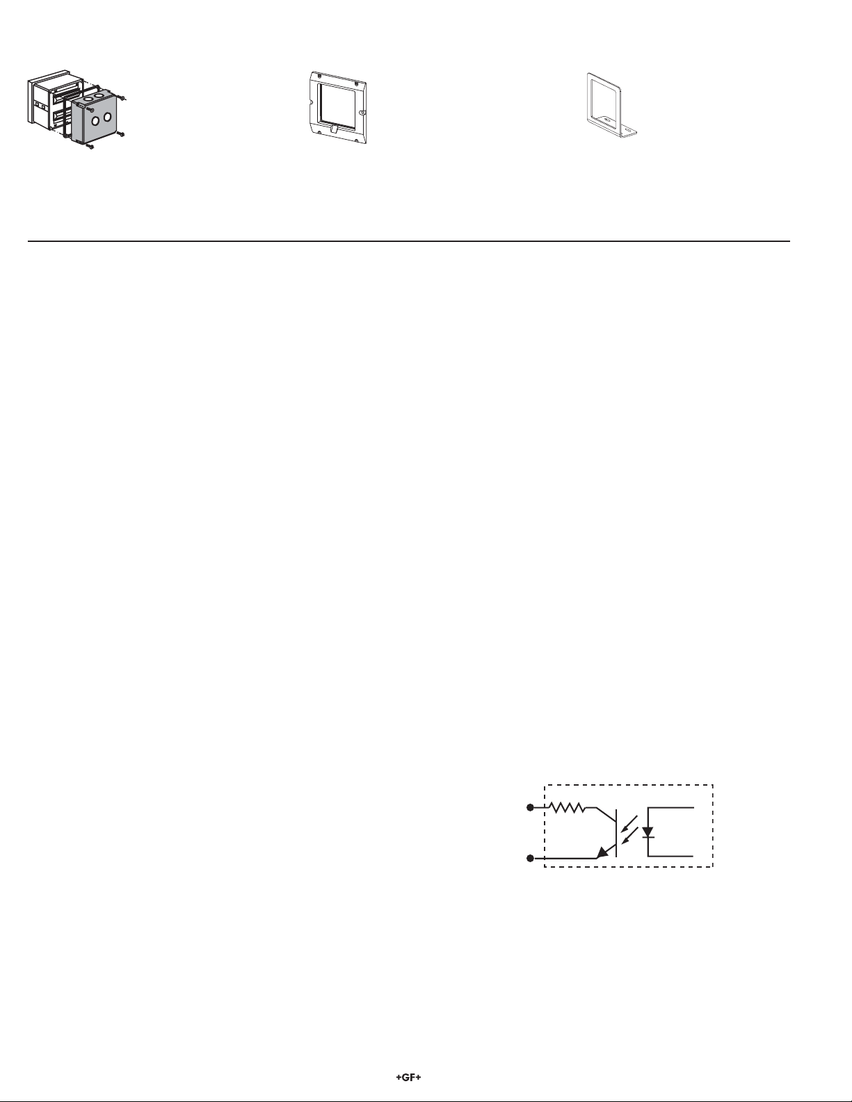
11. Parts and Accessories
Splashproof rear cover
#3-5000.395
(code 198 840 227)
• Power supply, 115 VAC - 24 VAC, #3-5000.075 (code 159 000 321)
• Front snap-on bezel, #3-5000.525-4 (code 159 001 221)
• 5600 instruction sheet #3-5600.090-1 (code 198 869 929)
5 x 5 inch adapter plate
for Signet retrofi t
#3-5000.399
(code 198 840 224)
12. Specifi cations
General
Sensor compatibility: All Signet fl ow sensors
Accuracy: ±0.5% of batch reading
Input: Optically isolated
Enclosure:
• Rating: NEMA 4X/IP65 front
• Dimensions: 1/4 DIN, 96 x 96 x 88 mm (3.8 x 3.8 x 3.5 in.)
• Case materials: ABS plastic
• Keypad material: Sealed 4-key silicone rubber
• Weight: Approximately 500 g (18 oz.)
Display:
• Type: Microprocessor controlled air-core meter movement and
alphanumeric 2 x 16 LCD
• Update rate: <200 ms
• Contrast: User selected
• Alarm annunciators: green batch LED (left), red option LED
(right)
Totalizers:
• 8-digit resettable with security option
• 8-digit non-resettable
Optional surface mount
bracket #3-5000.598
(code 198 840 225)
Agency Approvals
• CE, CSA, UL listed
• Manufactured under ISO 9001 and ISO 14001
Electrical
Power:
• 12 to 24 VDC or 12 to 24 VAC, unregulated, 50-60 Hz,
10 W max.
Contacts (2 sets):
• Mechanical SPDT contacts
• Maximum voltage rating: 5 A @ 30 VDC, 5 A @ 125 VAC, or
3 A @ 250 VAC, (power factor = 1.0)
Current output:
• 4 to 20 mA, non-isolated, internally powered
• Update rate: <200 ms
• Max loop impedance: 350 Ω max with a 12 V instrument supply
voltage, 950 Ω max with a 24 V instrument supply voltage
• Accuracy: ±0.1% of max range
Totalizer (CNT)/End of batch (EOB) pulse outputs:
• Open-collector transistor, optically isolated, 5 mA max. sink,
28 VDC max. pull-up voltage, 130 ms (CNT) pulse width
• End of batch pulse output 500 ms (fi xed)
Environmental
Operating temp.: -10 to 55 °C (14 to 131 °F), 50 °C (122 °F)
max. with optional rear cover
Storage temp.: -15 to 80 °C (5 to 176 °F)
Relative humidity: 0 to 95%, non-condensing
Altitude: 4000 m max.
Pollution degree: 2
8 of 12
Internal EOB/CNT Circuit
+
100 Ω
GND
Noise immunity: EN50082-2
Noise emissions: EN55011
Safety: EN61010-1
Signet 5600 Batch Controller
Page 9
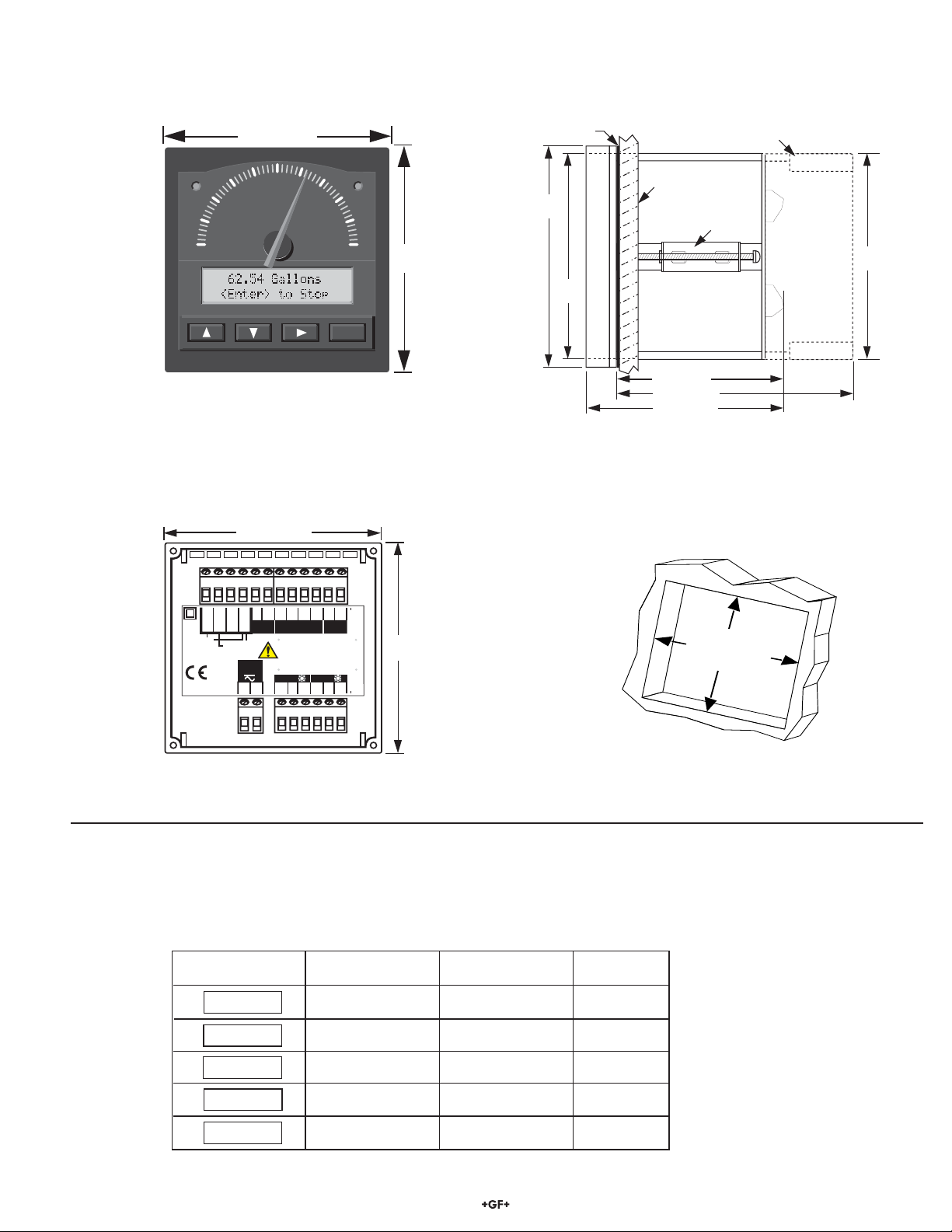
Dimensions:
Front
View
96 mm (3.8 in.)
+GF+
60
Batch Option
40
%
Batch
20
80
0
Signet Controller
88 mm (3.5 in.)
100
ENTER
96 mm
(3.8 in.)
96 mm
(3.8 in.)
91 mm
(3.6 in.)
Panel
Gasket
Optional Splashproof Rear Cover (sec. 11)
Mounting Panel
Mounting Clamp (2 ea.)
SIDE VIEW
76 mm (3 in.)
96 mm (3.8 in.)
88 mm (3.5 in.)
88 mm
(3.5 in.)
Std. Sensor
Signet
Model #3-5600
Freq. IN
Freq. IN
Sen. Pwr.
Open Collector
Sensor
12-24 V
10 W
+
+
CNT/EOB
Iso. Gnd
output
-
Gnd
Option
NO
Start
Stop
Remote
C
+
-
RTN
Rsm
Current
output
Patent No. D 376,328 Batch
Batch
NC
NO
C
NC
Rear
View
13. Quick Reference Menu Parameters
13.1 VIEW Menu Setup Parameters (sec. 10.1)
Parameters
A.
100.0 Gallons
<ENTER> to Start
B.
Batch Volume:
100.000 Gallons>
Gallons X 1
C.
Total:1234567.8>
Gallons X 1
D.
°Total:1234567.8
Overrun: Manual
E.
0.00000 Gallons
Menu
Display
Description
Press ENTER to start, stop,
or resume batch
Programmed
batch volume
Resettable
totalizer
Permanent
totalizer
• Overrun mode
• Overrun volume
88 mm
(3.5 in.)
Range
See programmed
batch volume B
0.00001 - 999999.
000000.00 - 99999999.
000000.00 - 99999999.
Manual or Auto
0.00000 - 999999.
Factory
Default
100.000
Gallons
100.000
Gallons
0000000.0
0000000.0
00000.0
92 x 92 mm
(3.62 x 3.62 in.)
Panel cutout
Signet 5600 Batch Controller
9 of 12
Page 10
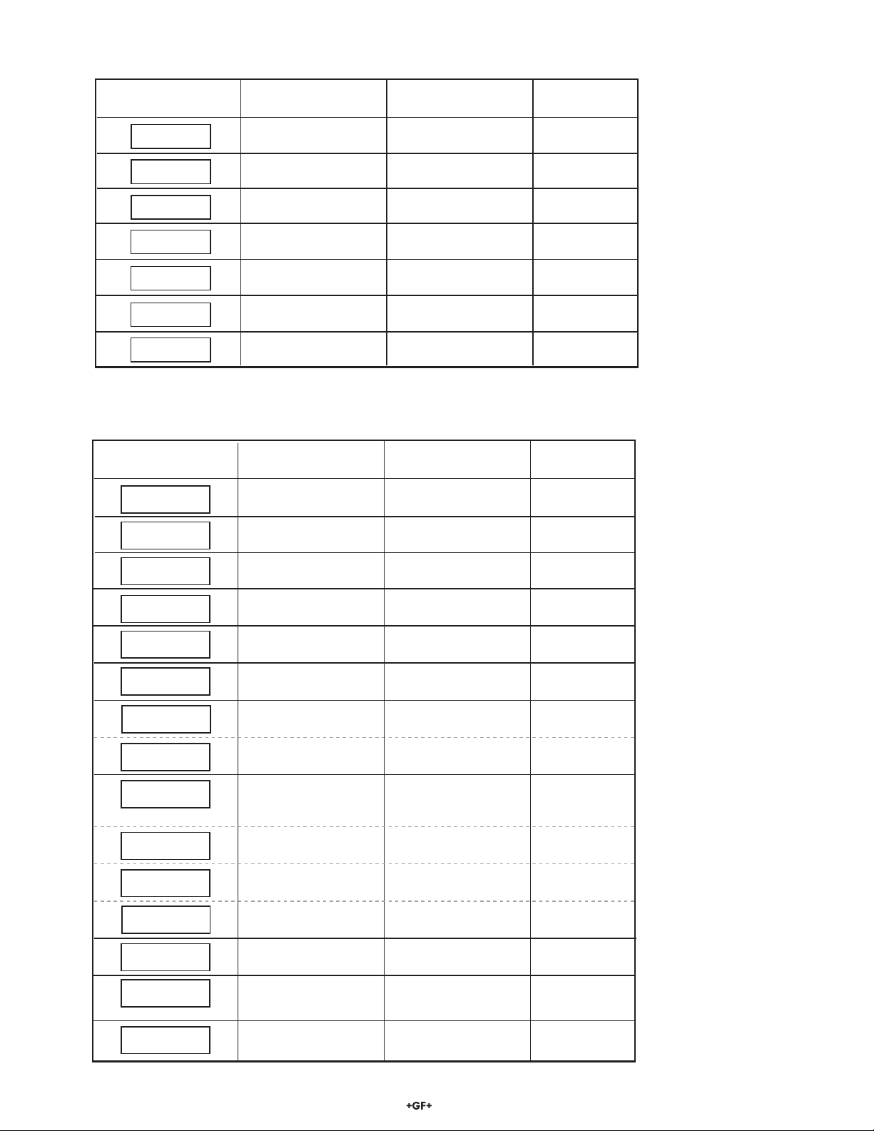
13.2 CALIBRATE Menu Setup Parameters (sec. 10.2)
Batch Units:
A.
Gallons >
Flow Timebase:
B.
m >
Auto Calibrate:
C.
Batch K-Factor >
Batch K-Factor:
D.
60.000 >
Total Units:
E.
Gallons x 1 >
Total K-Factor:
F.
60.000 >
Last CAL:
G.
01-01-98
Menu
Parameters
Display
Description
Batch units
Flow timebase
Optional volumetric
calibration
Batch K-Factor
Total units
Total K-Factor
Last Calibration
date
13.3 OPTIONS Menu Setup Parameters (sec. 10.4)
Menu
Parameters
Contrast:
A.
3 >
Display Decimal:
B.
*****.*
>
Total Decimal:
C.
*******
.
Lock:
D.
OFF >
Operating Mode:
Advanced >
E.
Pulse Output:
Totalizer >
F.
Overrun Comp:
Manual >
G.
Overrun Volume:
0.00000 Gallons>
Option Contact:
Missing Signal >
H.
>
*
Display
Description
Display contrast
Flow
decimal
Total
decimal
VIEW menu total/batch
volume reset access code
Simple or
Advanced
Pulse output
operation mode
Overrun compensation
mode
Overrun
volume
Option contact
mode
Range
Aa - Zz, 0 - 9, /, _
(8-digits max.)
Ss, Mm, Hh, Dd
n/a
0.0001 - 99999.
Az - Zz, 0 - 9, /, _
(15-digits max.)
0.0001 - 99999.
00 - 00 - 00 to
39 - 39 - 99
Range
0 to 5
**.*** to *****.
******.** to ********.
On or Off
n/a
End of Batch or
Totalizer
Manual or Auto
0.00000 - 999999.
Missing signal, Two stage,
Overrun alarm, End of Batch,
Off
Factory
Default
_Gallons
m
(m= minutes)
n/a
60.000
Gallons X 1
60.000
01 - 01 - 98
Factory
Default
3
****.*
*******.*
Off
Advanced
Totalizer
Manual
0.00000 Gallons
Missing
signal
_= blank display
digit option
_ = blank display
digit option
10 of 12
Two Stage
Setpoint%: 95.0>
Overrun Alarm:
1.00000 Gallons>
Missing Signal
Alarm: On >
I.
Missing Signal
Delay: 30.0 sec >
J.
Current Output:
BatchCompletion>
Count Direction:
K.
Down >
Option contact,
two stage mode
Option contact,
overrun alarm mode
Missing signal
alarm
Missing signal
alarm delay
Current output mode
Batch count direction
0.00 % - 100. %
0.00001 - 999999.
On or Off
0.10 - 999
seconds
Batch Completion, Valve
control, or
End of Batch
Count up or
down
95.0%
1.00000 Gallons
On
0.10 seconds
Batch
Completion
Count
up
Signet 5600 Batch Controller
Page 11
14. Maintenance
E
N
T
E
R
Clean the instrument case and front panel with a soft cloth and mild liquid soap solution.
15. Troubleshooting
Display Problem Solution
-- -- -- --Gallons/m Display timebase too large Change fl ow timebase (S=Seconds, M=Minutes, H=Hours,
<ENTER> to START D=Days) in CALIBRATE menu to a smaller value
(e.g. GPD to GPM)
Time Left - - - min Remaining batch time greater than Display will show actual remaining minutes after the remaining
<ENTER> to Stop 999 minutes (overrange) batch time is less than 999 minutes
-0001.8 Gallons Flow rate detected after batch end Repair leaky or stuck fl ow shuttoff valve.
<ENTER> to Start
Flow K-Factor Flow (batch) display K-Factor cannot Enter K-Factor greater than zero (sec. 10.2D)
cannot be zero be zero
Total K-Factor Totalizer K-Factor cannot be Enter K-Factor greater than zero (sec. 9.2E)
cannot be zero zero
Must be between Missing signal time delay must be set Enter missing signal time delay within 0.10 - 999 seconds
0.10 - 999 for 0.10 - 999 seconds (sec. 10.4I)
Overrun Volume Overrun alarm volumetric setting Enter overrun alarm volumetric setpoint within 0.00100 -
cannot be zero must be within 0.00100 - 999999. 999999.) engineering units (sec. 10.4H)
engineering units
Power Failure Instrument power interrupted during Use RIGHT arrow key to select “Resume” or “Clear”.
Resume Clear active batch process Selecting resume will continue the batch from the point where
the power interruption occurred. Selecting clear will clear the
power failure. After your selection has been
made, press ENTER to continue.
Setup Read Error Power fault occurred while saving Press any key to reload factory defaults then reprogram fl ow
Press any Key setup menu entry system setup parameters. Note: Totalizer displays remain
undistrubed and will resume after instrument reset.
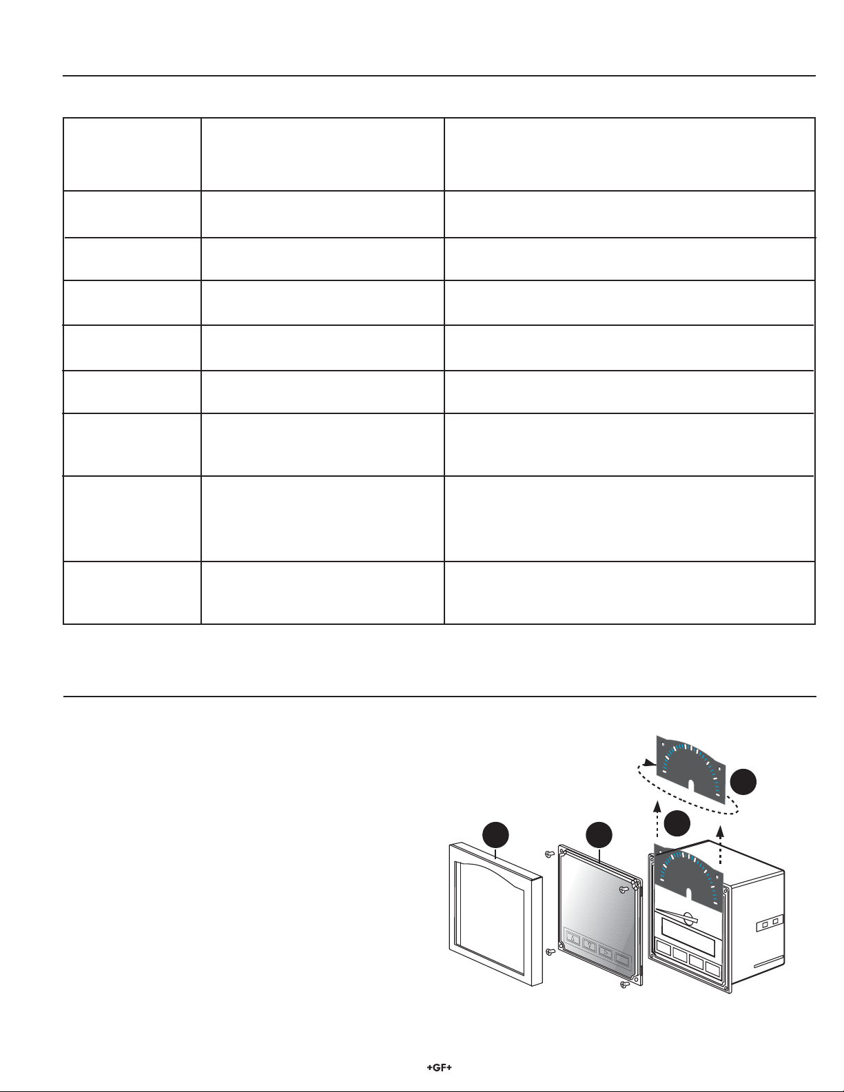
Dial Selection
• The analog display shows percentage of batch complete.
• The reversible dial scales are 0 to100%, or 100 to 0%.
• The instrument is shipped with the 0 to 100% scale installed.
• Reverse the face plate for either scale.
• Meter defl ection is fi xed from left to right.
Signet 5600 Batch Controller
0
-
100
BA
A
L
A
A
L
A
R
M
R
M
1
1
100
C
Batch
0
%
Batch
%
A
L
A
R
M
2
D
0
A
L
A
R
M
2
100
11 of 12
Page 12

George Fischer Signet, Inc., 3401 Aerojet Avenue, El Monte, CA 91731-2882 U.S.A. • Tel. (626) 571-2770 • Fax (626) 573-2057
For Worldwide Sales and Service, visit our website: www.gfsignet.com • Or call (in the U.S.): (800) 854-4090
3-5600.090-1 (E-8/04) English © George Fischer Signet, Inc. 2001 Printed in U.S.A. on recycled paper
 Loading...