

Page 1
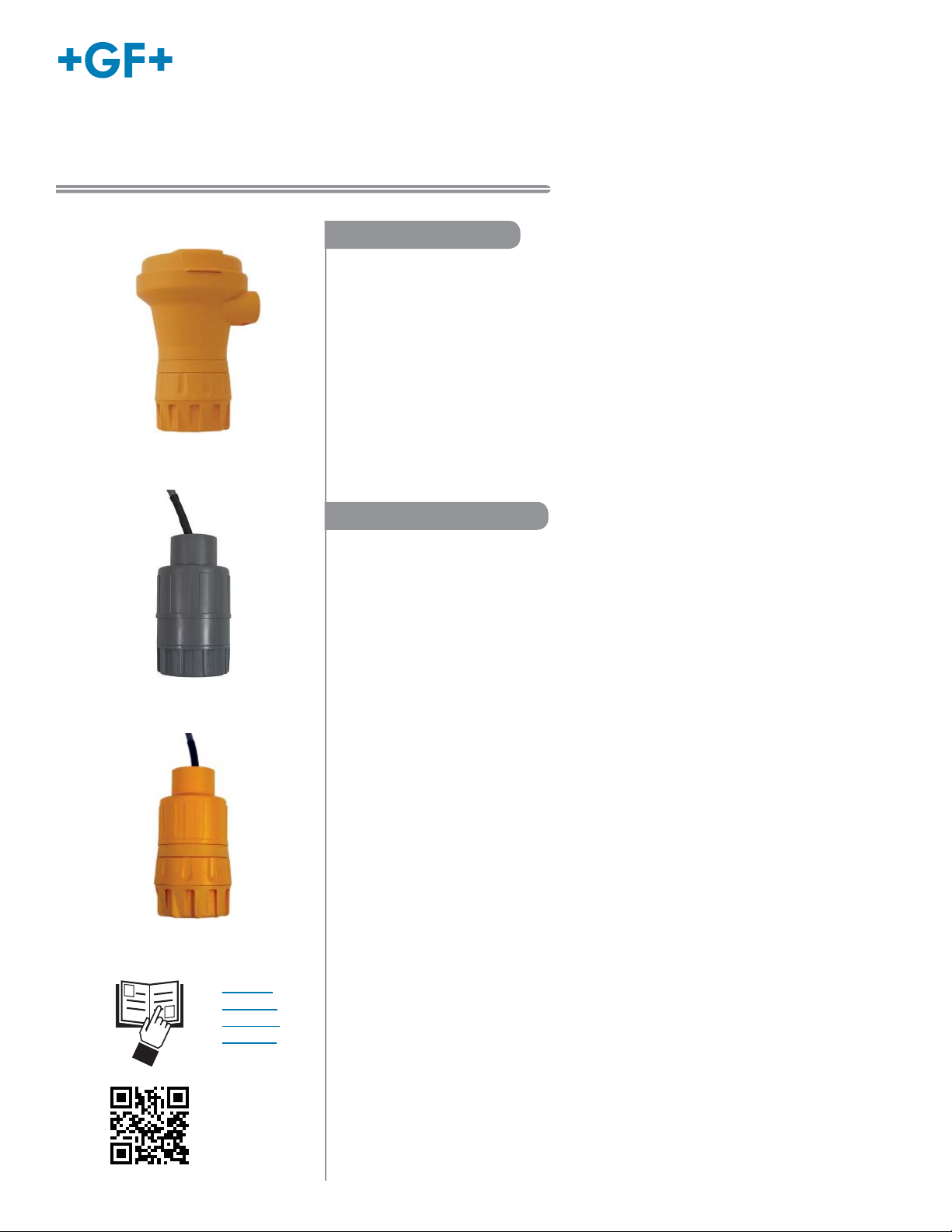
Signet 2750 DryLoc® pH/ORP Sensor Electronics
*3-2750.090*
3-2750.090 Rev. N 10/16
English
Operating Instructions
2750-1, 2750-2
2750-3, 2750-4
2750-7
Description
Signet 2750 pH/ORP Sensor Electronics provide two-wire 4 to 20 mA loop output for
pH and ORP measurements, without the expense of local display and other luxuries
available in full-featured transmitters. Preamplifi cation is built-in, reducing system costs
while ensuring absolute signal integrity up to 305 m (1,000 ft).
These sophisticated fi eld-mount devices also provide digital (S
Sensor Electronics self-confi gure for pH or ORP operation via automatic recognition of
electrode type, and the DryLoc
for submersible and in-line installations.
NEMA 4X Junction Boxes are integral parts of the in-line versions (2750-1, 2750-2,
and 2750-7) and are available as accessories for the submersible versions (2750-3
and 2750-4). The optional EasyCal feature allows simple push-button calibration and
includes an LED for visual feedback.
®
electrode connector quickly forms a robust assembly
3
L) output. The 2750
Table of Contents
Warranty Information ...............................................................................2
Product Registration ................................................................................2
Safety Information ...................................................................................2
Chemical Compatibility ............................................................................2
Specifi cations .......................................................................................2-3
In-Line Installation Notes .........................................................................3
In-Line Dimensions ..................................................................................3
Mounting Position ....................................................................................4
In-Line Assembly ..................................................................................4-5
Submersible Installation .......................................................................5-6
Digital (S3L) Wiring ..................................................................................6
4 to 20 mA Loop Wiring ...........................................................................7
Calibration ...............................................................................................7
Troubleshooting .......................................................................................8
Ordering Information................................................................................8
• English
• Deutsch
• Français
• Español
Page 2
Chemical CompatibilityWarranty Information
Refer to your local Georg Fischer Sales offi ce for the most
current warranty statement.
All warranty and non-warranty repairs being returned must
include a fully completed Service Form and goods must be
returned to your local GF Sales offi ce or distributor.
Product returned without a Service Form may not be
warranty replaced or repaired.
Signet products with limited shelf-life (e.g. pH, ORP, chlorine
electrodes, calibration solutions; e.g. pH buffers, turbidity
standards or other solutions) are warranted out of box but not
warranted against any damage, due to process or application
failures (e.g. high temperature, chemical poisoning, dry-out) or
mishandling (e.g. broken glass, damaged membrane, freezing
and/or extreme temperatures).
Product Registration
Thank you for purchasing the Signet line of Georg Fischer
measurement products.
If you would like to register your product(s), you can now register
online in one of the following ways:
• Visit our website www.gfsignet.com. Under Service and
Support click on Product Registration Form
• If this is a pdf manual (digital copy), click here
Safety Information
1. Depressurize and vent system prior to installation or removal.
2. Confi rm chemical compatibility before use.
3. Do not exceed maximum temperature/pressure specifi cations.
4. Wear safety goggles or faceshield during installation/service.
5. Do not alter product construction.
6. When using chemicals or solvents care should be taken
and appropriate eye, face, hand, body, and/or respiratory
protection should be used.
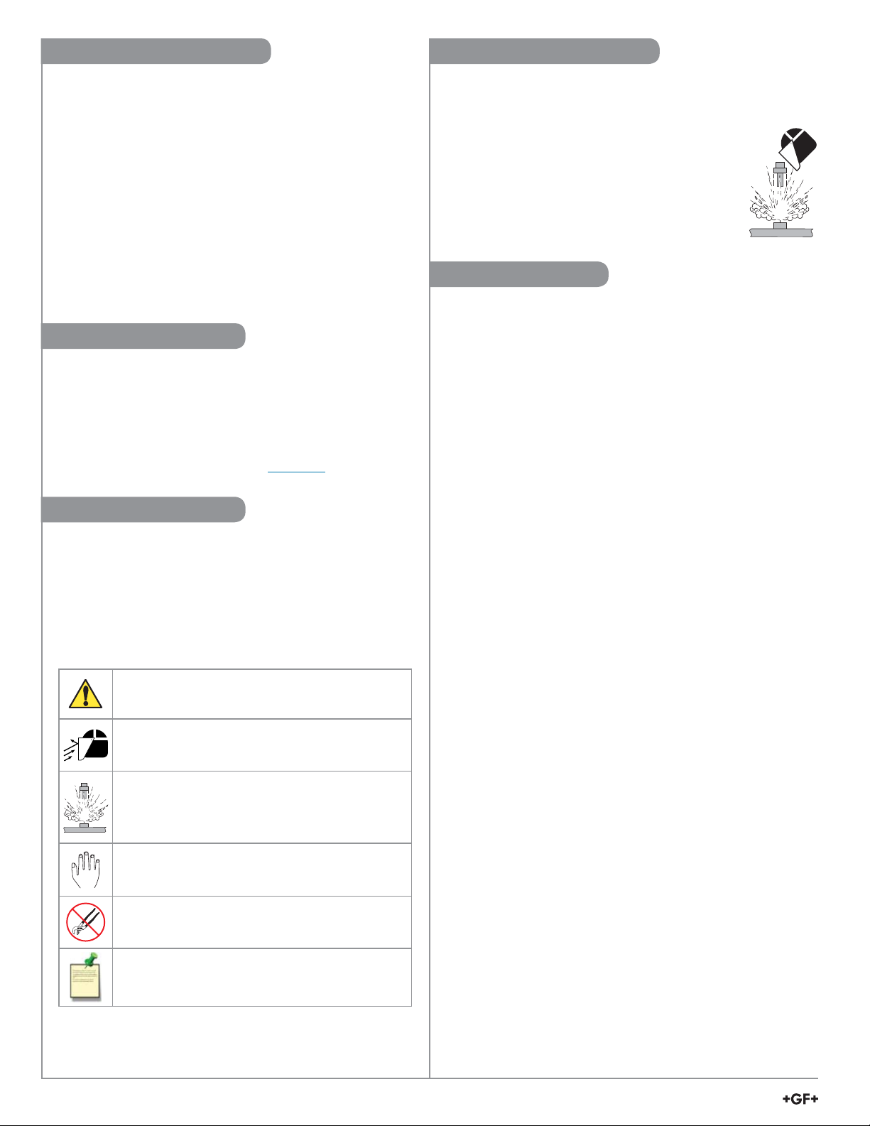
Caution / Warning / Danger
Indicates a potential hazard. Failure to follow all warnings
may lead to equipment damage, injury, or death
Personal Protective Equipment (PPE)
Always utilize the most appropriate PPE during
installation and service of Signet products.
Pressurized System Warning
Sensor may be under pressure, take caution to vent
system prior to installation or removal. Failure to do so
may result in equipment damage and/or serious injury.
Hand Tighten Only
Overtightening may permanently damage product threads
and lead to failure of the retaining nut.
Do Not Use Tools
Use of tool(s) may damage product beyond repair and
potentially void product warranty.
Note / Technical Notes
Highlights additional information or detailed procedure.
The retaining nuts of pH and ORP sensors are not designed
for prolonged contact with aggressive substances.
Strong acids, caustic substances and solvents
or their vapor may lead to failure of the retaining
nut, ejection of the sensor and loss of the process
fl uid with possibly serious consequences, such as
damage to equipment and serious personal injury.
Retaining nuts that may have been in contact with
such substances e.g. due to leakage or spilling,
must be replaced.
Specifi cations
General
Compatible Electrodes ......... Signet DryLoc Electrodes
(PT1000 or 3K Balco temperature
sensor versions for pH)
Operational Range 2750 ...... 0.00 to 14.00 pH, ±2000 mV ORP,
0 °C to 85 °C (32 °F to 185 °F)
Response Time (includes electrode response):
pH ..................................... <6 s for 95% of change
ORP .................................. application dependent
pH Temp T90 ................... 200 s (2724 and 2734)
132 s (2726 and 2736)
438 s (2756-WT)
Materials
In-line:
2750-1, 2750-2, 2750-7..... PBT (thermal plastic polyester)
Submersible:
2750-3, 2750-4 .................. CPVC
Cable for 2750-3, 2750-4, 2750-7:
• 5 m (15 ft) 3-conductor shielded, 22 AWG
• May be extended up to 305 m (1000 ft) with current output
• May be extended up to 305 m (1000 ft) with (S
Shipping Weight
2750-1, 2750-2 ...................... 0.75 kg (1.75 lb)
2750-3, 2750-4, 2750-7 ........ 0.64 kg (1.4 lb)
Environmental
Ambient Temp. ..................... 0 °C to 85 °C (32 °F to 185 °F)
Storage Temp. ..................... -20 °C to 85 °C (-4 °F to 185 °F)
Relative Humidity ................. 95% max, non-condensing
Immunity ............................... EN50082-2
Emissions ............................. EN50081-1
Enclosure Rating
In-line:
2750-1, 2750-2
, 2750-7
.... NEMA 4X/IP65
(with electrode connected)
Submersible:
2750-3, 2750-4 ................. NEMA 6P/IP68
(with electrode and watertight
extension pipe connected)
Electrical
Input Impedance .................. >10
11
Ω
Input response time ............. 500 ms
Temperature drift.................. ±0.002 pH per ºC,
±0.1 mV ORP per ºC
Input resolution ..................... 0.02 pH, 1 mV ORP, 0.3 ºC
3
L) output
2
2750 DryLoc pH/ORP Sensor Electronics
Page 3
Specifi cations
In-Line Dimensions
Current Output
pH ......................................... Fixed 4 to 20 mA,
isolated, 0 to 14 pH
(custom scaling available)
ORP ...................................... Fixed 4 to 20 mA, isolated,
–1000 to 2000 mV (custom scaling
available, –2000 to 2000 mV)
Power ................................... Regulated 12-24 VDC ± 10%,
20 mA max.
Max Loop Resistance .......... 50 Ω max. @ 12V
325 Ω max. @ 18V
600 Ω max. @ 24V
Accuracy .............................. ±32 μA @ 25 ºC
Temperature drift.................. ±1 μA per ºC
Output resolution .................. ± 5 μA
Error indication ..................... 3.6 mA
Digital (S
3
L) Output:
Description ........................... Serial ASCII, TTL level 9600 bps
Power ................................... 5 VDC ± 10% regulated, 3 mA max
Accuracy:
pH ..................................... ± 0.03 pH @ 25 °C
ORP .................................. ± 2 mV @ 25 °C
Resolution:
pH ..................................... 0.01 pH
ORP .................................. 1 mV
Temp. ............................... 0.2 °C
Error indication ..................... Temp output "+999.9"
Standards and Approvals
• CE, RoHS Compliant
• Manufactured under ISO 9001 for Quality,
ISO 14001 for Environmental Management and
OHSAS 18001 for Occupational Health and Safety.
China RoHS (Go to www.gfsignet.com for details)
Declaration of Conformity according to FCC Part 15.
This device complies with Part 15 of the FCC rules.
Operation is subject to the following two conditions:
(1) This device may not cause harmful interference, and,
(2) This device must accept any interference received,
including interference that may cause undesired operation.
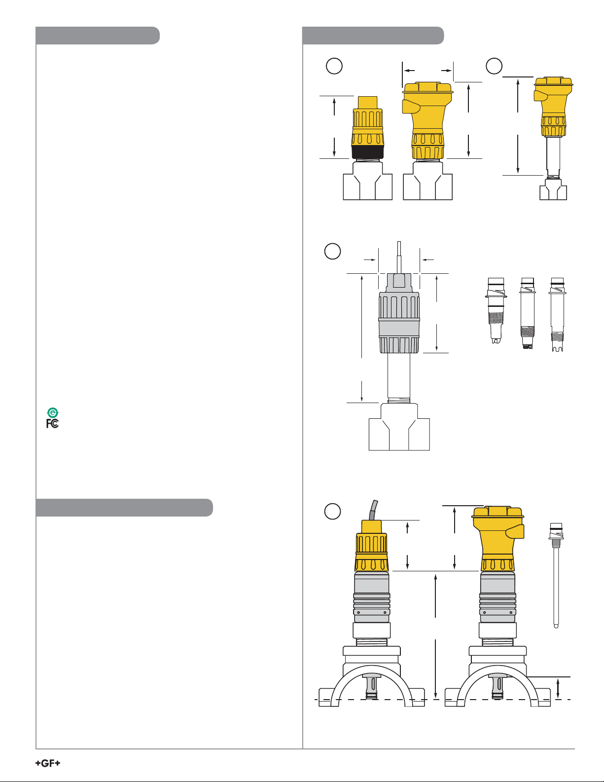
1 2
117 mm
(4.6 in.)
2750-1, 2750-2 and 2750-7 with 272X, 273X, 2764 or 2774 sensors
3
94 mm
(3.7 in.)
140 mm
(5.5 in.)
55 mm
(2.16 in.)
229 mm
(9.0 in.)
*
102 mm
(4 in.)
190.6 mm
(7.5 in.)
2750-3 and 2750-4 with
2764 or 2774 sensors
* NOTE:
Lubricate O-rings with a
non-petroleum based,
viscous lubricant (grease)
compatible with the system.
**
In-Line Installation Notes
• A Signet installation fi tting (12.7 mm to 101.6 mm
1
[
/2 in. to 4 in.]) or a threaded tee is required to secure the
electrode in the pipe.
• The Signet Measurement and Instrumentation catalog offers
a complete selection of fi ttings.
• 2724, 2734, 2764, and 2774 series sensors thread directly
into standard 1 in. or ¾ in. NPT fi ttings.
1. 2750-1 and 2750-7 In-Line sensor (without EasyCal) are
designed for applications where electrode calibration is
facilitated by remote equipment. A 8050-2 or 8052-2 junction
box is required to use EasyCal with the 2750-1 or 2750-7.
2. 2750-2 In-Line sensor includes EasyCal.
3. The 2750
recommended for in-line applications using the 2764 series
differential sensors and the 2774 series Threaded DryLoc
sensors.
EasyCal with the 2750-3 or 2750-4.
4. 2756 and 2757 Wet-Tap sensors require the 3719 Wet-Tap
assembly and can use the 2750
-
3 and 2750-4 submersible sensor electronics are
A 8050-2 or 8052-2 junction box is required to use
-
1, 2750-2 or 2750-7 versions.
4
83 mm
(3.27 in.)
114 mm
(4.5 in.)
248 mm
(9.75 in.)
*
2750-1, 2750-2 and 2750-7 with
3719 and 2756 or 2757 Wet Tap Sensors
2750 DryLoc pH/ORP Sensor Electronics
*
45 mm
(1.75 in.)
*
3
Page 4
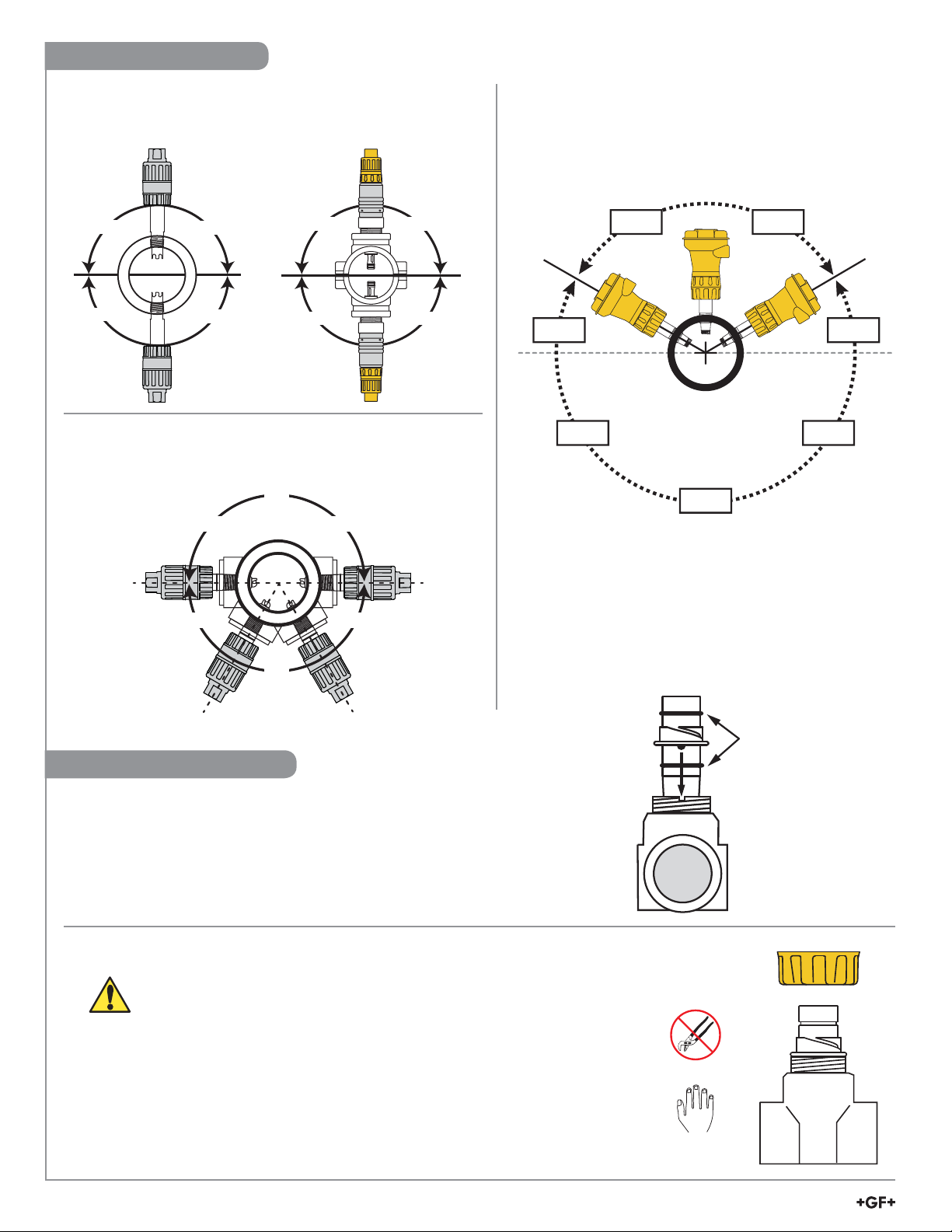
Mounting Position
Wet-Tap electrodes, 2724, 2734, and 2774 series electrodes
Mounting Angle using GF Signet Fittings.
*Avoid locations with air pockets and/or sediment (90° and 270°).
*
OK
OK
OK
OK
OK OK
OKOK
*
When mounting in a standard threaded fi tting, the electrode must
be mounted horizontal to 60 degrees below horizontal position only:
90°
NO
NO NO
2764 series electrodes MUST be mounted upright.
• Vertical (0°) position optimum.
• DO NOT install within 30º of horizontal (Contact factory
for horizontal or inverted installation requirements).
Vertical ± 60°
YESYES
30°30°
NONO
NO
NO
NO
180°
240°
YESYES
NO
270°
300°
0°
2750 In-Line Assembly
NOTE:
This procedure applies to systems using 2724-2726 and 2734-2736 electrodes.
If the 3719 pH/ORP Wet-Tap is used, refer to the 3719 manual for instructions.
1. Insert electrode into Signet installation fi tting.
Seat the electrode tabs into the alignment notches in the fi tting.
2. Thread the in-line retaining nut onto fi tting to secure the electrode into place.
HAND-TIGHTEN THE THREADED NUT ONTO THE INSTALLATION FITTING.
DO NOT USE TOOLS! DO NOT USE THREAD SEALANT OR LUBRICANTS
ON THE FITTING THREADS OR THE SENSOR CAP.
Lubricate O-rings with a
non-petroleum based,
viscous lubricant
(grease) compatible
with the system.
Retaining nut
Chemical Compatibility Warning
• The retaining nuts of pH and ORP sensors are not designed for prolonged contact
with aggressive substances.
• Strong acids, caustic substances and solvents or their vapor may lead to failure of
the retaining nut, ejection of the sensor and loss of the process fl uid with possibly
serious consequences, such as damage to equipment and serious personal injury.
• Retaining nuts that may have been in contact with such substances e.g. due to
leakage or spilling, must be replaced.
4
2750 DryLoc pH/ORP Sensor Electronics
Page 5
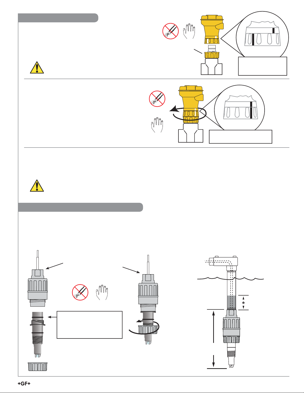
2750 In-Line Assembly
NOTE:
Keep the electrical interconnection between electrode and
sensor electronics dry and clean at all times.
3. Unlock the ring on base of 2750 (The ring is unlocked when
the lines on the ring and body of the 2750 are not aligned.)
LUBRICATE O-RINGS WITH A NON-PETROLEUM BASED,
VISCOUS LUBRICANT (GREASE) COMPATIBLE WITH THE SYSTEM.
4. Place 2750 onto top of electrode and turn
until the assembly drops into position.
5. Turn locking ring
(The ring is locked when the line on the ring and
the line on the body of the 2750 are aligned.)
1
/4 turn to secure the 2750 assembly.
Locking Ring
Unlocked
The molded alignment
marks are enhanced
for clarity.
Locked
The molded alignment marks
are enhanced for clarity.
In-Line Sensor and Electrode Removal
• To remove electronics assembly only: Turn locking ring
• To remove electrode from the pipe: Remove electronics assembly, then unthread retaining nut; pull electrode straight up.
• To remove the complete 2750 system: Hold locking ring in place. Unthread retaining nut and pull electrode straight up.
CAUTION!
• Do not remove the electrode from a pressurized pipe.
• Wear appropriate protective clothing when working with chemicals in pressurized pipe.
1
/4 turn; lift assembly straight up.
2750-3, 2750-4 Submersible Installation
1. Insert electrode into base of the
2750-3 or 2750-4 and turn until
keyed contacts are seated.
NOTE: Lubricate O-ring if
installing sensor is diffi cult.
2750-3: ¾ in. NPT threads
2750-4: ISO 7-1/R¾ threads
Lubricate O-rings with a
non-petroleum based, viscous
lubricant (grease) compatible
with the system.
NOTE:
Keep the electrical interconnection
between electrode and sensor
electronics dry and clean at all times.
2. Thread retaining nut over
electrode and hand-tighten
onto 2750.
3. Attach ¾ in. watertight pipe to the top of the 2750.
Secure the threaded connection to prevent any leakage.
* For additional defense against possible accumulation
of condensation at the back seal area of the sensor, fi ll
the lower 75 mm to 100 mm (3 in. to 4 in.) of conduit or
extension pipe with a fl exible sealant such as silicone.
221 mm
(8.7 in.)
2750 DryLoc pH/ORP Sensor Electronics
5
Page 6
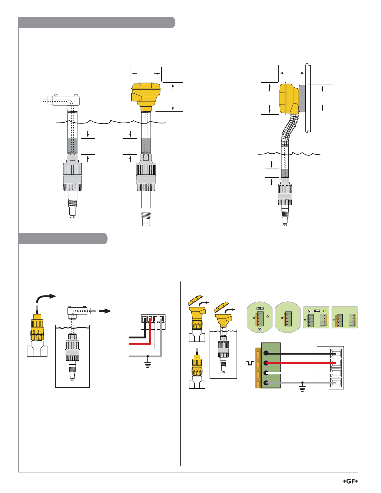
2750-3, 2750-4 Submersible Installation
Use standard installation
hardware to connect the
submersible 2750-3 or
2750-4 directly to
external equipment.
Fill with 75 mm to 100 mm
*
(3 in. to 4 in.) of sealant
The 8052-1 NPT Mount Junction box
(or 8052-2 with EasyCal) connects
to ¾ in. pipe or conduit and provides
convenient wiring termination.
94 mm
(3.7 in.)
107 mm
(4.2 in.)
Cable supplied: 5 m (15 ft)
3-conductor + shield, 22 AWG.
• May be extended up to 305 m
(1000 ft) with current output.
• May be extended up to 305 m
(1000 ft) with Digital (S
OROR
3
L) output.
The 8050-1 Universal Mount junction
box (or 8050-2 with EasyCal)
mounts fl at onto a wall or can
be strapped to a post or pipe.
107 mm
(4.2 in.)
94 mm
(3.7 in.)
82.5 mm
(3.25 in.)
½ in. NPT
threads
*
Digital (S3L) Wiring
• When the 2750 is powered with 5 VDC, the digital (S3L) serial data output is automatically selected.
• (S3L) data is used exclusively by Signet instruments.
• Remove approximately 10 mm (0.4 in.) of insulation and tin each conductor before inserting into connectors.
• To add the EasyCal function to the 2750-1, 2750-3, 2750-4 and 2750-7, use the 8050-2 or 8052-2 junction box.
Digital (S
3
L) with no junction box Digital (S
9900 S3L Inputs
SHLD
DATA
GND
V+
Black
Red
White
Shield
Optional Earth ground
• Connect the 2750 cable directly to digital (S3L) terminals.
• 8900 and 9900 users:
If this direct wiring is used, set the CALIBRATE menu to
perform Calibration at "INSTRUMENT"
• Connect the terminals as shown to any digital (S3L) terminals.
• 8900 and 9900 users:
3
L) with Junction box
2750-2
SW2
Run Cal
+
-
S
+
-
S
4
3
2
1
SW1
2750-1
+
D1
-
S
Black
4
Red
3
White
2
Shield
1
Optional Earth ground
4
3
2
1
If using EasyCal, set the CALIBRATE menu to either perform
Calibration at "SENSOR" or "INSTRUMENT"
• If SENSOR, use standard pH buffer values (pH 4, 7, or 10;
ORP 87 and 264 mV) to perform periodic calibration.
• If INSTRUMENT, any pH/ORP value can be used.
8050-2, 8052-2
SW2
SW1
Cal
Run
+
-
S
9900 S
8050-1, 8052-1
D1
+
-
S
3
L Inputs
V+
DATA
GND
SHLD
6
2750 DryLoc pH/ORP Sensor Electronics
Page 7
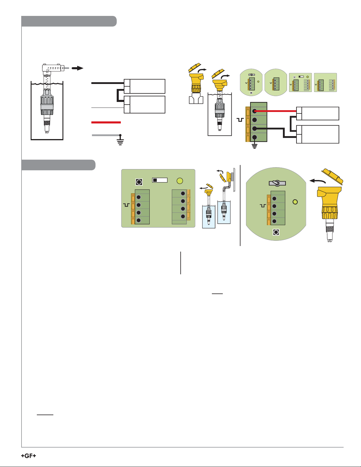
4 to 20 mA Loop Wiring
• When the 2750 is powered with 12 to 24 VDC, the 4 to 20 mA loop output is automatically selected.
• Remove approximately 10 mm (0.4 in.) of insulation and tin each conductor before inserting into connectors.
• To add the EasyCal function to the 2750-1, 2750-3 and 2750-4, use the 8050-2 or 8052-2 junction box.
Current Loop with no junction box Current loop with Junction box
2750-1
4
+
D1
SW1
3
2
-
1
S
Red
4
3
Black
2
1
Black
White
Red
Shield
Power Supply
+
12 to 24 VDC
-
PLC or Recorder
-
Loop Input
+
4 to 20 mA
No Connection
Optional Earth ground
+
-
S
Optional Earth ground
2750-2
SW2
Run Cal
4
+
3
2
-
1
S
Calibration
All 2750 pH/ORP Sensor
Electronics are factory-calibrated for
maximum out-of-the-box accuracy.
Periodic calibration is required to
compensate for electrode aging.
The optional EasyCal feature allows
calibration to be performed local to
the sensor.
Run
SW2
Cal
D1
SW1
+
-
S
8052-2
8050-2
SW2
Run Cal
+
-
S
4
3
2
1
SW1
8050-2, 8052-2
SW2
SW1
Cal
Run
+
-
S
+
-
PLC or Recorder
-
+
D1
8050-1, 8052-1
D1
+
-
S
Power Supply
12 to 24 VDC
Loop Input
4 to 20 mA
Required Equipment:
2750-2
• 2750-2 with built-in EasyCal
or
• Any 2750 with 8050-2 or 8052-2 junction box with EasyCal
• Standard pH buffers (pH 4, 7 or 10)
SW1 EasyCal button
SW2 RUN/CALIBRATE switch for (S
D1 EasyCal Indicator (green LED)
3
L) system
EasyCal Procedure:
The fi rst step (Reset) is recommended each time an electrode is replaced, but is NOT necessary upon initial installation or periodic
calibration.
In fact, for periodic calibration it is best for the electrode/sensor assembly to remain intact to minimize the possibility of moisture or other
contamination entering the electrical interconnection area. The electrode/sensor connection must remain dry and clean at all times.
1. Reset the 2750 pH/ORP Sensor Electronics to factory calibration: With no electrode connected to the Sensor, press and hold SW1
until the LED (D1) comes on steady then goes off again (approx. 10 seconds). When the LED goes off, release SW1; reset is complete.
2. Connect an electrode to the 2750 pH/ORP Sensor Electronics.
3. If digital
(S3L) output is being used, place SW2 in the “Cal” position. If 4 to 20 mA output is being used, SW2 position is of no
consequence.
4. Place the electrode/sensor assembly into a calibration solution as follows: (If the electrode is “healthy”, then the 2750 will automatically
recognize the solution. The order in which the solutions are used during the calibration procedure is of no consequence).
• For pH calibration, use any two of these international standards: pH 4.0, 7.0 or 10.0 buffer solutions.
(Signet part number 3-0700.390 contains one capsule of each value)
• To produce standards for ORP calibration, mix the chemical Quinhydrone into pH 7.0 and 4.0 buffers to saturation (⅛ g per 50ml).
• Regardless of the size of the container used for calibration, one inch of solution is adequate to completely submerge the tip of the
electrode.
• Allow at least 30 seconds for the electrode response to stabilize before calibration.
5. Press and hold SW1 for approximately 8 to 10 seconds. During this time, the LED (D1) will come on steady then go back off.
Release SW1 (If the LED blinks several times rapidly, the calibration was not successful. See the troubleshooting section.)
6. Remove the electrode/sensor assembly from the fi rst calibration solution, rinse the electrode with clean water, and place it in a
second solution. Allow at least 30 seconds for the electrode response to stabilize before calibration.
7. Press and hold SW1 for approximately 8 to 10 seconds. During this time, the LED will come on steady then go back off.
Release SW1. (If the LED blinks several times rapidly, the calibration was not successful. See the troubleshooting section.)
8. For digital (S
3
L) systems ONLY : Return SW2 to the RUN position.
Calibration is complete. Return the system to service.
2750 DryLoc pH/ORP Sensor Electronics
7
Page 8

Troubleshooting
LED and Output Condition Possible Causes Suggested Solutions
Current Output: LED off,
current output is 3.6 mA
Digital (S3L): Transmitter (8900 or
9900) displays "Check Sensor"
During EasyCal, the LED blinks
rapidly for 4 seconds and the
current output is frozen at a
random fi xed value.
After completing calibration
procedure, the output values
are inaccurate.
• No electrode installed.
• Bad/dirty contacts between
electrode and 2750.
• Buffer solution is outside of the
accepted tolerance for the 2750.
• The electrode is depleted
(> 1.1 pH or 65 mV offset).
• Insuffi cient time allowed for
electrode stabilization during
calibration.
• Install electrode.
• Check interconnection between electrode and 2750,
clean contacts, and/or lubricate sensor o-ring.
• pH system: Use fresh 4 pH, 7 pH, or 10 pH buffer and
restart the calibration.
• ORP system: Use fresh 4 pH and 7 pH buffer solution
saturated with Quinhydrone, or Light's Solution.
• Clean or replace the electrode.
Recalibrate:
• Verify that test solutions are at room temperature
• Wait at least 30 seconds after placing electrode in
solution before pressing S1 EasyCal button.
Ordering Information
DryLoc pH/ORP Sensor Electronics
Mfr. Part No. Code Description
3-2750-1 159 000 744 In-line Sensor Electronics with Junction Box
3-2750-2 159 000 745 In-line Sensor Electronics with Junction Box and EasyCal
3-2750-3 159 000 746 Submersible Sensor Electronics with 4.6 m (15 ft) cable, ¾ in. NPT threads
3-2750-4 159 000 842 Submersible Sensor Electronics with 4.6 m (15 ft) cable, ISO 7-1/R¾ threads
3-2750-7 159 001 671 In-line Sensor Electronics, Digital (S
3-2750-8 In-line Sensor Electronics, with 4.6 m (15 ft) cable, ISO 7-1/R¾ threads (Special Order Only)
3
L), with 4.6 m (15 ft) cable, ¾ in. NPT threads
Parts and Accessories
3-0700.390 198 864 403 pH Buffer Kit
3-2700.395 159 001 605 Calibration kit: included 3 PP cups, cup stand, 1 pint pH 4.01, 1 pint pH 7.00
3-2759 159 000 762 pH/ORP Simulator/System tester
3-2759.391 159 000 764 Adapter cable to connect 2759 and 2750
3-8050-1 159 000 753 Universal Mount Junction Box
3-8050-2 159 000 754 Universal Mount Junction Box with EasyCal
3-8052-1 159 000 755 ¾ in. NPT mount Junction Box
3-8052-2 159 000 756 ¾ in. NPT mount Junction Box with EasyCal
3-9900.392-1 159 000 839 Liquid tight connector kit, NPT (1 connector)
3-9900.392-2 159 000 840 Liquid tight connector kit, PG 13.5 (1 connector)
3822-7004 159 001 581 pH 4.01 buffer solution, 1 pint (473 ml) bottle
3822-7007 159 001 582 pH 7.00 buffer solution, 1 pint (473 ml) bottle
3822-7010 159 001 583 pH 10.00 buffer solution, 1 pint (473 ml) bottle
3822-7115 159 001 606 20 gram bottle Quinhydrone for ORP calibration
5523-0322 159 000 761 Cable, 3-conductor + shield (blk/red/wht/shld) 22 AWG (per ft)
P31515-0P200 159 000 630 Universal Pipe Adapter PVC
P31515-0C200 159 000 631 Universal Pipe Adapter CPVC
P31515-0V200 159 000 459 Universal Pipe Adapter PVDF
3-8050.390-1 159 001 702 Retaining Nut Replacement Kit, NPT, Valox
3-8050.390-3 159 310 116 Retaining Nut Replacement Kit, NPT, PP
®
Georg Fischer Signet LLC, 3401 Aero Jet Avenue, El Monte, CA 91731-2882 U.S.A. • Tel. (626) 571-2770 • Fax (626) 573-2057
For Worldwide Sales and Service, visit our website: www.gfsignet.com • Or call (in the U.S.): (800) 854-4090
For the most up-to-date information, please refer to our website at www.gfsignet.com
3-2750.090 Rev. N 10/16 English © Georg Fischer Signet LLC 2016
 Loading...