


Copyright © 2016 Geophysical Survey Systems, Inc.
All rights reserved
including the right of reproduction
in whole or in part in any form
Published by Geophysical Survey Sy stem s, Inc.
40 Simon Street
Nashua, New Hampshire 03060-3075 USA
Printed in the United States
SIR, RADAN and UtilityScan are registered trademarks of Geophysical Survey Systems, Inc.

Geophysical Survey Systems, Inc. StructureScan™ Mini XT
Manual
Limited Warranty, Limitations Of Liability And Restrictions
Geophysical Survey Systems, Inc. hereinafter referred to as GSSI, warrants that for a period of
24 months from the delivery date to the original purchaser this product will be free from defects in
materials and workmanship. EXCEPT FOR THE FOREGOING LIMITED WARRANTY, GSSI
DISCLAIMS ALL WARRANTIES, EXPRESS OR IMPLIED, INCLUDING ANY WARRANTY OF
MERCHANTABILITY OR FITNESS FOR A PARTICULAR PURPOSE. GSSI's obligation is limited to
repairing or replacing parts or equipment which are returned to GSSI, transportation and insurance prepaid, without alteration or further damage, and which in GSSI's judgment, were defective or became
defective during normal use.
GSSI ASSUMES NO LIABILITY FOR ANY DIRECT, INDIRECT, SPECIAL, INCIDENTAL OR
CONSEQUENTIAL DAMAGES OR INJURIES CAUSED BY PROPER OR IMPROPER OPERATION
OF ITS EQUIPMENT, WHETHER OR NOT DEFECTIVE.
Before returning any equipment to GSSI, a Return Material Authorization (RMA) number must be
obtained. Please call the GSSI Customer Service Manager who will assign an RMA number. Be sure to
have the serial number of the unit available
Regulatory Information
The use of GSSI antennas is governed by different regulatory agencies around the world. Specific antenna
models must be certified for legal operation in your country. Please read and understand the following
regulatory passages that pertain to your antenna. A listing of certified antennas by region can be found
www.geophysical.com/regulatoryinformation.htm
.
Notice
Operation is subject to the following two conditions: (1) this device may not cause interference, and (2)
this device must accept any interference, including interference that may cause undesired operation of the
device.
Survey Wheels
All of GSSI’s antennas are designed to operate with survey wheels. Some antennas have built-in survey
wheels, including the 62000 Palm Antenna and the Mini-SIR. The series of concrete antennas, including
the 5100, 5101 and 52600, have survey wheels built in to their special carts, the 614 and 615. The larger
antennas, including the 3101D, 5103, 50400 and 5104 are used in the larger carts, the 623 and 643, which
have survey wheels built in to them. Various sizes of survey wheels can also be attached directly to these
antennas. This includes the 611, 620 and 622. For highway surveys we use the 630 Distance measuring
Instrument (DMI).

Geophysical Survey Systems, Inc. StructureScan™ Mini XT
Manual
Garantie limitée, limites de responsabilité et restrictions
Geophysical Survey Systems, Inc, ci-après dénommé GSSI, garantit à l'acheteur original de ce produit
que, pendant une période de 24 mois à compter de la date de livraison, ce dernier sera exempt de défauts
de matériaux et de fabrication. EXCEPTE POUR CETTE GARANTIE LIMITÉE, GSSI REJETTE
TOUTE GARANTIE, EXPLICITE OU IMPLICITE, Y COMPRIS TOUTE GARANTIE DE QUALITE
MARCHANDE OU D'ADEQUATION A UN USAGE PARTICULIER. L’obligation de GSSI est limitée
à la réparation ou le remplacement de pièces ou équipements qui sont retournés à GSSI, transport et
assurance prépayés, sans altération ni d'autres dommages, et qui, d’après GSSI, étaient défectueux ou sont
devenus défectueux lors d’une utilisation normale.
GSSI N'ASSUME AUCUNE RESPONSABILITE POUR LES DOMMAGES DIRECTS, INDIRECTS,
SPÉCIAUX, INCIDENTS OU CONSEQUENTS OU BLESSURES CAUSEES PAR UNE BONNE OU
MAUVAISE UTILISATION DE SON EQUIPEMENT DÉFECTUEUX OU NON.
Avant de retourner tout équipement à GSSI, une autorisation de retour matériel (RMA) doit être obtenue.
Appelez s'il vous plaît le service clientèle GSSI qui attribuera un numéro de RMA. Soyez sûr d'avoir le
numéro de série de l'unité.
Informations réglementaires
L'utilisation des antennes GSSI est régie par différents organismes de réglementation à travers le monde.
Certains modèles d'antenne spécifiques doivent être certifiés pour un fonctionnement légal dans votre
pays. Merci de lire et comprendre les passages suivants de réglementation qui s'appliquent à votre
antenne. Une liste des antennes certifiées par région peut être trouvée sur www.geophysical.com /
regulatoryinformation.htm.
Avis
La mise en œuvre est soumise aux deux conditions suivantes: (1) cet appareil ne doit pas provoquer
d'interférences et (2) cet appareil doit accepter toute interférence, y compris les interférences qui peuvent
causer un fonctionnement non désiré de l'appareil.
Roues codeuses – Odomètres
Toutes les antennes GSSI sont conçus pour fonctionner avec des roues codeuses. Certaines antennes,
comprenant l'antenne 62000 Palm et le Mini-SIR, intègrent directement les roues codeuses. La série
d'antennes pour le béton, comprenant les 5100, 5101 et 52600, ont des roues codeuses intégrées à leurs
chariots spéciaux, les 614 et 615. Les antennes plus grandes, telles que la 3101D, 5103, 50400 et 5104
sont utilisées dans les chariots plus grands, les 623 et 643, qui ont des roues codeuses intégrées.
Différentes tailles de roues codeuses peuvent être également être fixées directement sur ces antennes,
comprenant les 611, 620 et 622. Pour les auscultations de chaussées nous utilisons l’odomètre 630 (DMI :
Distance Measuring Instrument).

Geophysical Survey Systems, Inc. StructureScan™ Mini XT
Manual
FCC Notice (for U.S. Customers):
This device complies with part 15, class F of the FCC Rules:
Operation is subject to the following conditions:
1. This device many not cause harmful interference, and
2. This device must accept any interference received, Including interference that may cause
undesired operation
Warning: Changes or modifications to this unit not expressly approved by the party responsible for
compliance could void the user’s authority to operate the equipment.
Operation of this device is restricted to law enforcement, fire and rescue officials, scientific research
institutes, commercial mining companies, construction companies and private parties operating on behalf
of these groups. Operation by any other party is a violation of 47 U.S.C. § 301 and could subject the
operator to serious legal penalties.
Coordination Requirements
(a) UWB imaging systems require coordination through the FCC before the equipment may be used. The operator shall comply with any constraints on equipment usage resulting from this coordination.
(b) The users of UWB imaging devices shall supply detailed operational areas to the FCC Office of
Engineering and Technology who shall coordinate this information with the Federal Government through
the National Telecommunications and Information Administration. The information provided by the
UWB operator shall include the name, address and other pertinent contact information of the user, the
desired geographical area of operation, and the FCC ID number and other nomenclature of the UWB
device. This material shall be submitted to the following address:
Frequency Coordination Branch, OET
Federal Communications Commission
445 12
Washington, D.C. 20554
ATTN: UWB Coordination
(d) Users of authorized, coordinated UWB systems may transfer them to other qualified users and to
different locations upon coordination of change of ownership or location to the FCC and coordination
with existing authorized operations.
(e) The NTIA/FCC coordination report shall include any needed constraints that apply to day-to-day
operations. Such constraints could specify prohibited areas of operations or areas located near authorized
radio stations for which additional coordination is required before operation of the UWB equipment. If
additional local coordination is required, a local coordination contact will be provided.
Notice: Use of this device as a wall imaging system is prohibited by FCC regulations.
th
Street, SW

Geophysical Survey Systems, Inc. StructureScan™ Mini XT
Manual

Geophysical Survey Systems, Inc. StructureScan™ Mini XT
Manual
For U.S. Customers
Ground Penetrating Radar Coordination Notice And Equipment Registration
Note: This form is only for Domestic United States users. The Federal Communications Commission
(FCC) requires that all users of GPR who purchased antennas after July 15th, 2002 register their
equipment and areas of operation. It is required that you fill out this form and fax or mail to the FCC.
Failure to do this is a violation of Federal law.
1. Date:
2. Company name:
3. Address:
4. Contact Information [contact name and phone number]:
5. Area Of Operation [state(s)]:
---Continued on next page.

Geophysical Survey Systems, Inc. StructureScan™ Mini XT
FCC ID (QF7 followed by
Model #)
Manual
6. Equipment Identification:
Brand Name: Geophysical Survey Systems, Inc.
Antenna Model No. (center frequency): List all antennas being registered.
Model Frequency
MINIXT 2700 MHZ QF7MINIXT
7. Receipt Date Of Equipment:
Fax this form to the FCC at: 202-418-1944
Or
Mail to:
Frequency Coordination Branch, OET
Federal Communications Commission
445 12
Washington, D.C. 20554
ATTN: UWB Coordination
Do not send this information to GSSI.
th
Street, SW

Geophysical Survey Systems, Inc. StructureScan™ Mini XT
Manual
Canadian Requirements for RSS-220
Canadian Requirements of RSS-220 for Ground Antennas
This Ground Penetrating Radar Device shall be operated only when in contact with or within 1 m of the
ground.
This Ground Penetrating Radar Device shall be operated only by law enforcement agencies, scientific
research institutes, commercial mining companies, construction companies, and emergency rescue or
firefighting organizations.
Cet appareil de radar de sol (ou géoradar) ne doit être utilisé qu’en contact avec le sol ou à 1 m maximum
au dessus du sol.
Cet appareil de radar de sol ne doit être utilisé que par les forces de l’ordre, les instituts de recherche
scientifiques, les sociétés minières, les sociétés de construction, et les organisations de secours d’urgence
ou de combat du feu.
Canadian Requirements of RSS-220 for Hand-held Antennas
This In-wall Radar Imaging Device shall be operated where the device is directed at the wall and in
contact with or within 20 cm of the wall surface.
This In-wall Radar Imaging Device shall be operated only by law enforcement agencies, scientific
research institutes, commercial mining companies, construction companies, and emergency rescue or
firefighting organizations.
Cet appareil de radar de structure (murs, poutres, dalles…) ne doit être utilisé qu’en contact avec la
structure ou à 20 cm maximum décollé de cette structure.
Cet appareil de radar de sol ne doit être utilisé que par les forces de l’ordre, les instituts de recherche
scientifiques, les sociétés minières, les sociétés de construction, et les organisations de secours d’urgence
ou de combat du feu.
Canadian Requirements of RSS-220 for Search and Rescue Antennas
This Through-wall Radar Imaging Device shall be operated only by law enforcement agencies or
emergency rescue or firefighting organizations that are under a local, provincial or federal authority. The
equipment is to be operated only in providing services and for necessary training operations.
Cet appareil de radar au travers des murs ne doit être utilisé que par les forces de l’ordre ou les
organisations de secours d’urgence ou de combat du feu qui sont sous une autorité locale, provinciale ou
fédérale. Cet équipement ne doit être utilisé que dans le cadre de services et pour les opérations
d’entrainement nécessaires.

Geophysical Survey Systems, Inc. StructureScan™ Mini XT
Manual
Declaration of CE Conformance
Geophysical Survey Systems, Inc. hereby confirms that the following named
products have been tested and meet the requirements of the European standards as indicated:
Models: 3101A, 5106A, 52600S, 62000, MINISIR, MINIHR, LL3P, LLTRx, 41000SA, 42000S,
50400S, 51600S, 50270S, D50300/800
Description: Ground Penetrating Radar Antennas
European Standards: ETSI EN 301 489-32 V1.1.1 (2005-09), ETSI EN 301 489-V1.6.1
(2005-09), ETSI EN 302 066-1 V1.1.1(2005-09), ETSI EN302 066-2 V1.1.1 (2005-09),
ETSI EN 302 066-1 V1.2.1(2008-02), ETSI EN302 066-2 V1.2.1 (2008-02),
ECC/DEC/(06)08
Place and Date of Issue: Intertek – ETL SEMCO 07.02.07, 03.11.09, 10.13.09, 11.18.09
Compliance Worldwide 03.23.12 09.25.12 04.14.14 11.10.15
Model: Profiler™ EMP-400
Description: Electromagnetic Induction System
European Standards: EN61326:1997 + A1:1998 + A2:2001
Place and Date of Issue: Intertek – ETL SEMCO 08.29.06
Model: FGDC-3000/2100, StructureScan™ EZ System, StructureScan™ MINI System
StructureScan™ MiniXT, StructureScan™EZXT
Description: Ground Penetrating Radar Data Acquisition Systems
European Standards: EN61000-6-2:2005, EN61000-4-2, EN61000-4-3, EN61000-4-4,
EN61000-4-5, EN61000-4-6, EN61000-4-11
Place and Date of Issue: Compliance Worldwide 09.29.09, 11.25.09 Intertek 08.31.15
Models: SIR
Description: Ground Penetrating Radar Data Acquisition System
European Standards: EN61000-6-4: 2007 per EN 55011:2009 + A1:2010
Place and Date of Issue: Compliance Worldwide 07.10.12, 07.11.12
Model: SIR
Description: Ground Penetrating Radar Data Acquisition System
European Standards: EN61000-6-4: 2007 per EN 55011:2009 + A1:2010
Place and Date of Issue: Compliance Worldwide 04.14.14
Chris Plumlee
1.08.15
Name of authorized person
®
30, SIR® 30E
®
4000

Geophysical Survey Systems, Inc. StructureScan™ Mini XT
Manual
Table of Contents
Chapter 1: Using the StructureScan Mini XT .........................................................................1
Section 1: Introduction ....................................................................................................... 1
StructureScan™ Mini XT ...................................................................................................... 2
Section 2: Getting Started.................................................................................................. 3
Section 3: Using ScanEZ Mode ......................................................................................... 5
Section 4: Using the Scan3D App ................................................................................. 10
Section 5: Using the ScanMax App .............................................................................. 14
Section 6: Calibrating for Depth in the ScanMax App ........................................... 20
Section 7: Using the DualScan App ............................................................................. 23
Section 8: File Management .......................................................................................... 26
Chapter 2: Using RADAN for StructureScan Mini ............................................................. 27
Setting up Your Laptop/PC and Data Transfer ........................................................ 27
Launching and Navigating the Software .................................................................. 28
Viewing and Processing the Data ................................................................................ 30
Processing the Data .......................................................................................................... 32
Ribbon Options .................................................................................................................. 34
Home Ribbon Options ..................................................................................................... 34
3D Volume Options Ribbon ........................................................................................... 40
Appendix A: The Dielectric Constant .................................................................................... 41
Appendix B: Data Interpretation and Examples of Common Features ................... 43
Appendix C: Technical Specifications ................................................................................... 47
Appendix D: Accessories ........................................................................................................... 49
Appendix E: Labeling .................................................................................................................. 52
MN 70-813 Rev C

Geophysical Survey Systems, Inc. StructureScan™ Mini XT
Manual

Geophysical Survey Systems, Inc. StructureScan™ Mini XT
Manual
Chapter 1: Using the
StructureScan Mini XT
Section 1: Introduction
Thank you for purchasing the StructureScan Mini XT by GSSI. StructureScan Mini XT is the very latest
product from GSSI’s line of cutting-edge GPR concrete inspection tools. The Mini XT is designed with
today’s busy concrete professional in mind. It’s a tool that packs a ton of simple to learn functionality into
a ruggedly reliable package. The Mini XT will turn in a solid day of work and be back on the job first
thing in the morning with no complaints.
What Comes in the Box
• StructureScan Mini XT
• StructureScan Mini XT transit case
• Two (2) rechargeable lithium ion
batteries
• Dual bay battery charger with AC power
adaptor and set of international plugs
• Tool to remove the XT’s handle
• Safety wrist strap
• Data collection grids (sample pack)
• Quick Start Guide
About this Manual
This document is the exhaustive user’s guide for the Mini XT. As such, it incorporates the information in
the printed Quick Start Guide as well as information for those applications not described in the Quick
Start. This manual also discusses tips and tricks for processing and presenting your data results in
RADAN, GSSI’s premier GPR data processing software. This is a living docum ent so be sure to
periodically check GSSI’s Technical Support Site: www.support.geophysical.com
updates, both to your Mini XT and to this document
GSSI also recommends that you take advantage of one of the training opportunities provided for the
Mini XT. GSSI offers a full suite of webinars, videos, and live training classes for you to deepen your
knowledge of GSSI products and GPR applications. Please visit www.geophysical.com
training@geophysical.com for more details.
for downloadable
or contact
MN 70-813 Rev C 1

Geophysical Survey Systems, Inc. StructureScan™ Mini XT
1
1 2 3 4 5
1
3 2 1
4
Manual
StructureScan™ Mini XT
Front/Top View
Back View
Ergonomic removable handle
and controls
2 Easy to use operator interface
with color display screen
3 Survey wheel encoder
4 Guiding laser for locating
5 Accessory attachment point
Power button
2 Battery slot
3 USB port
4 Battery release
MN 70-813 Rev C 2
Geophysical Survey Systems, Inc. StructureScan™ Mini XT
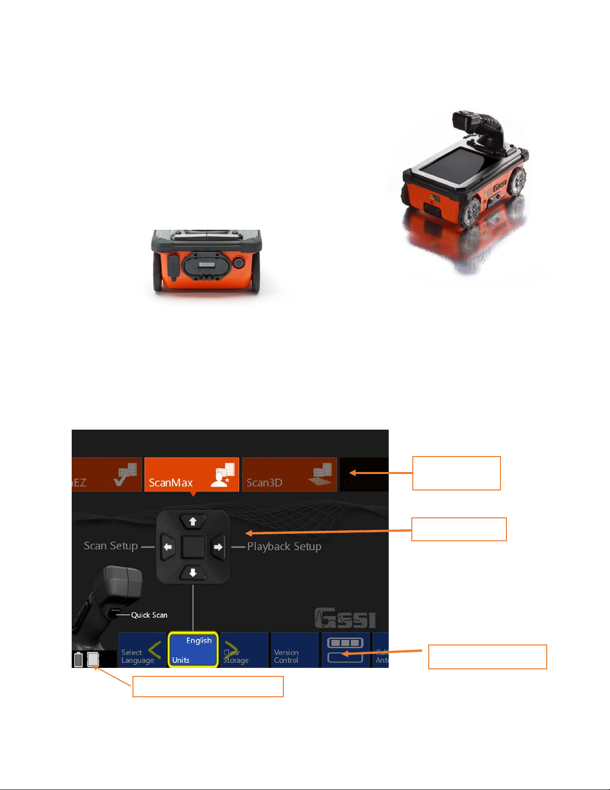
App Selection
Handle Keypad
Menu Carousel Softkeys
Battery and Storage Indicators
Manual
Section 2: Getting Started
1 Remove any protective tape from the wheels.
2 GSSI recommends fully charging the batteries prior to use.
3 Insert a fully charged battery into the battery slot. The battery
should be inserted with the small plastic tabs pointing down.
Gently push the battery in until the plastic battery release clips
on the Mini XT catch on the battery tabs.
4 Push the Power Button to turn on the Mini XT. The Mini XT is powering up and on when the Blue
ring on the button is illuminated. After a few moments the Mini XT Main menu screen will appear.
Note: The Mini XT incorporates a power-saving Sleep feature. The Mini XT is asleep when the
screen goes black and the blue ring around the power button pulses. Pushing any of the buttons on the
handle control keypad will wake the Mini XT. You can modify the sleep settings and power
management plan in the ScanMax App.
The Main Menu Screen
Carousel
MN 70-813 Rev C 3
Geophysical Survey Systems, Inc. StructureScan™ Mini XT
Secondary Menu
Manual
First Time Setup
Note: The Mini XT incorporates a touch screen. You can use the handle keypad or touchscreen to access
most of the menu items.
Setting UI App Mode
The StructureScan Mini XT apps are divided into two categories for ease of use. These categories are
referred to as UI Modes. The UI Modes are accessible from the menu carousel, secondary menu:
• Simple Mode: ScanEZ
• Standard Mode: ScanEZ, ScanMax, Scan3D
• Advanced Mode: ScanEZ, ScanMax, Scan3D, DualScan
For first time setup, make sure that the Mini XT is in Standard UI mode.
1 Set Language: Make sure that the Mini XT is in ScanMax App. Click the Down arrow to highlight
the menu carousel and then the Left/Right arrows to choose Select Language. Click the middle
keypad button or press the softkey on the carousel to select. Choose your desired language. This may
cause the Mini XT to restart.
2 Set Units: In the ScanMax App, choose Units from the menu carousel. Click the middle handle
keypad button to press the softkey to toggle between English (Imperial) and Metric units.
3 Calibrate Antenna: In the ScanMax App, select Calibrate Antenna from the menu carousel. Follow
the onscreen instructions. Calibrating will set appropriate gain levels.
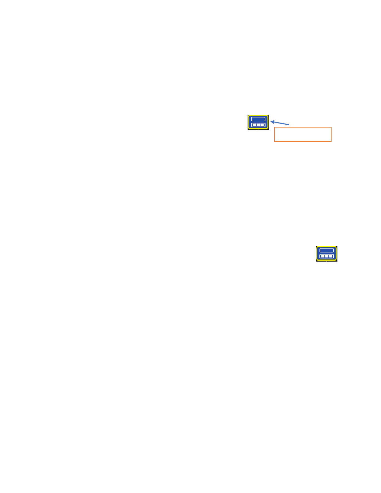
4 Set Date/Time: In the ScanMax App, choose the secondary menu softkey: Click the middle
handle button or push the softkey to toggle to the ScanMax secondary menu carousel.
Follow the onscreen instructions to set the appropriate date and time.
The choices you have made here will carry over to the ScanEZ and the Scan3D Collection Apps.
MN 70-813 Rev C 4
Geophysical Survey Systems, Inc. StructureScan™ Mini XT
Manual
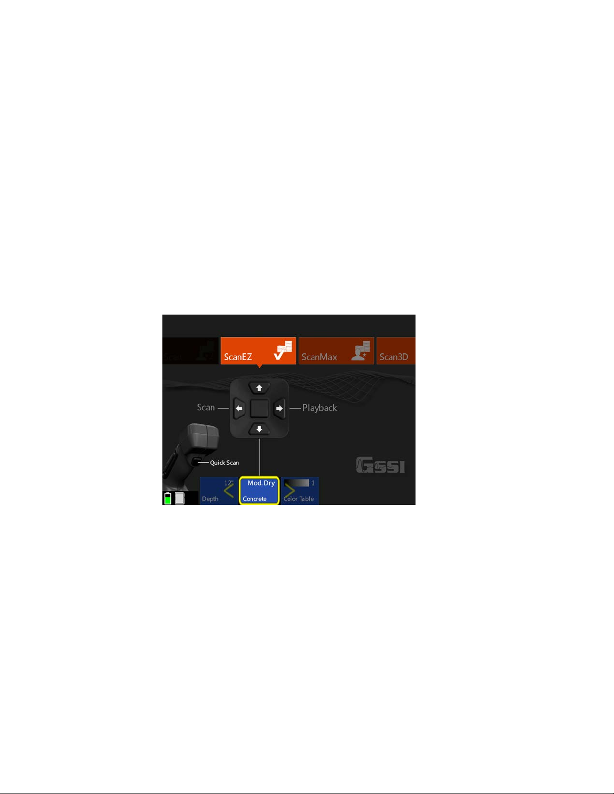
Section 3: Using ScanEZ Mode
Configuring the Mini XT
Before collecting any data, you may want to configure your Mini XT. Choose ScanEZ from the
App Carousel.
1 Choose Inspection Depth: Possible options are 4, 8, 12, 16, 20 inches or 10, 20, 30, 40, 50 cm.
GSSI recommends setting the inspection depth a little deeper than required.
2 Set Concrete Curing Level: GPR energy travels at different speeds though concrete which is at
different cure levels. Setting this accurately will allow for more accurate depth readings. These names
refer to the concrete’s cure, not any surface water. See Appendix A in this guide for details.
3 Choose Color Table: This will set the data display color. GSSI recommends that new users choose
Color Table 1.
4 Once you have configured the XT, pull the trigger or select Scan from the handle keypad to begin
collecting data.
MN 70-813 Rev C 5
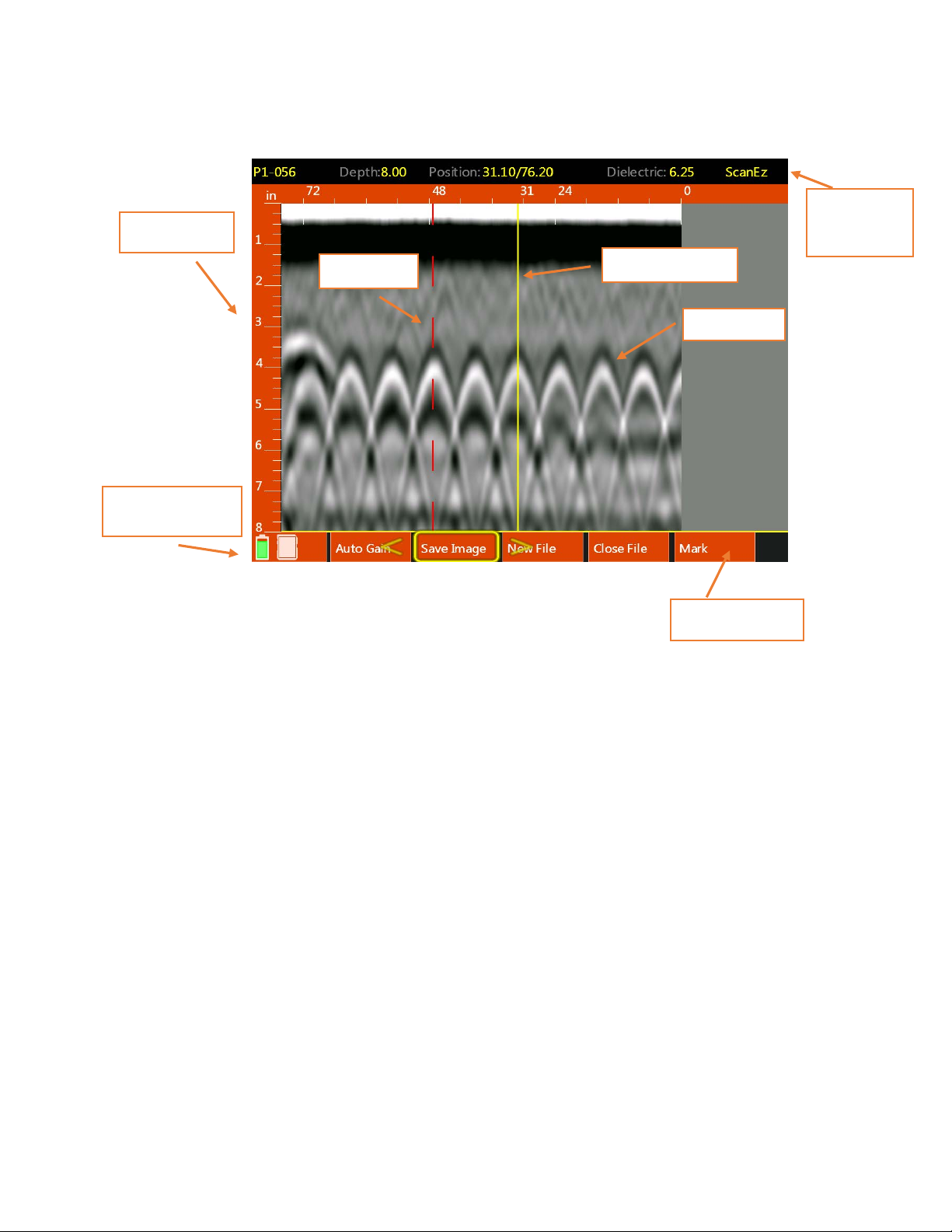
Geophysical Survey Systems, Inc. StructureScan™ Mini XT
Depth Scale
Battery/Storage
Status
Backup Cursor
User Mark
File
Bar
Menu Carousel
Hyperbola
Manual
Understanding the Mini XT Screen
Information
5 If you haven’t already done so, pull trigger to begin collecting data and roll
the Mini XT across the concrete. The data image will be displayed in real time.
6 The project and file number will be displayed at the top-left corner of the screen. The Menu Carousel
will display different options depending on whether the Mini XT is adding new data to the screen or
using the Backup Cursor to review data already collection.
While adding new data, the menu carousel will have the following options:
• New File: This will stop and save your current file and begin collecting a new one. The file number
in the top-left corner will advance by 1.
• Mark: This will write a red-dashed user mark to the scan that is being written when the option is
pushed. This is useful to note the location of something you want to remember.
• Close File: This will stop and save the current file and return you to the ScanEZ menu screen.
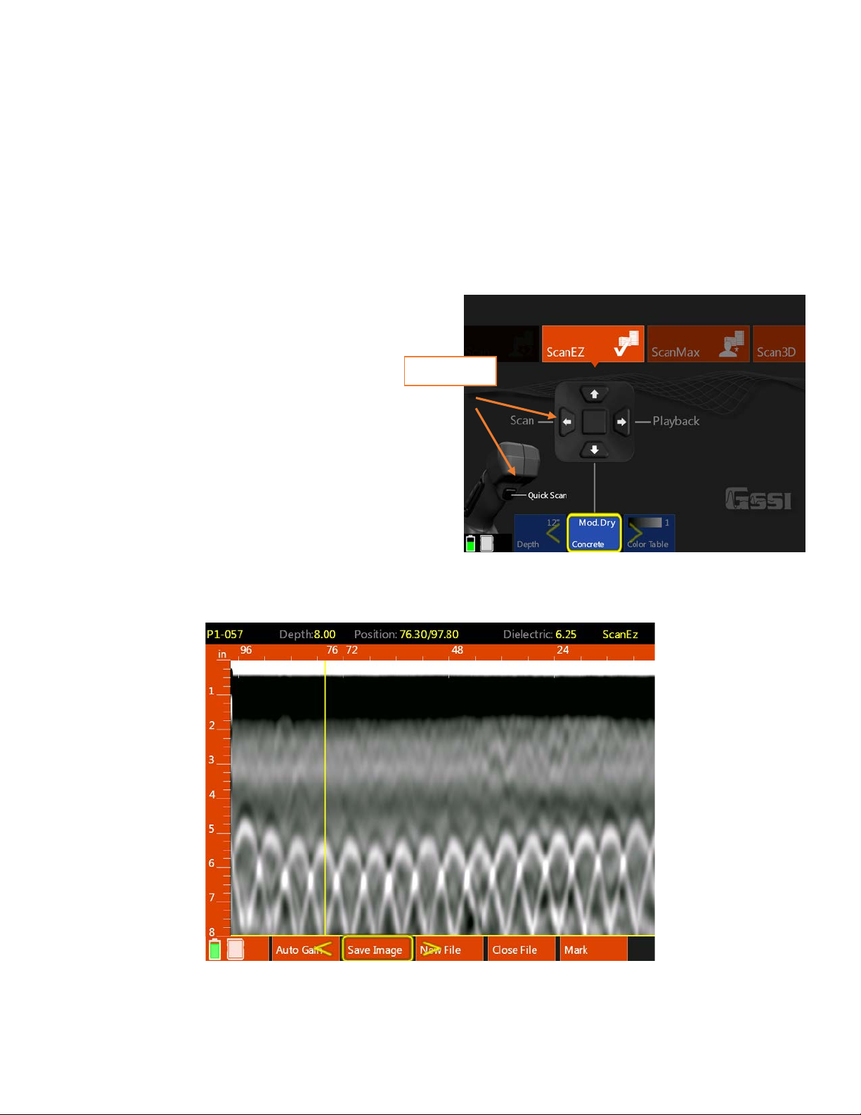
While using the Backup Cursor, the menu carousel will have the following options:
• Auto Gain: This will adjust the screen brightness to either brighten up under-gained (weak) im ag es
or dampen over-gained (saturated) images.
• Save Image: This will store a screen shot as a PNG image format. Each image will have the same
name as the GPR data file. Multiple images of the same GPR file will have a letter tag added. For
example: FILE__056A, FILE__056B, etc.
MN 70-813 Rev C 6
Geophysical Survey Systems, Inc. StructureScan™ Mini XT
Start Scan
Manual
• New File: This will stop and save your current file and begin collecting a new one. The file number
in the top-left corner will advance by 1.
• Close File: This will stop and save the current file and return you to the ScanEZ menu screen.
• Mark: This will write a red-dashed user mark to the Backup Cursor location when the option is
pushed. This is useful to note the location of something you want to remember.
Collecting Data and Marking Targets
This section covers the steps to locate and mark out objects in 2D.
1 From the ScanEZ Main menu, pull the trigger or
select Scan from the handle keypad to begin.
Roll the Mini XT along the area to be
scanned. The system will display data in
real time as you are rolling it.
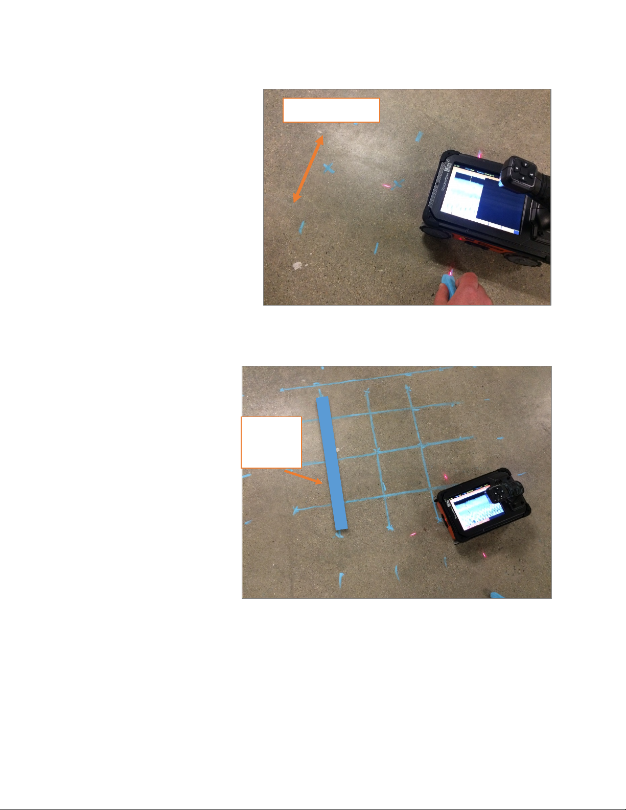
2 Back the Mini XT up in a straight line. You will see
a yellow vertical line (the backup cursor) appear on
the screen. The position of this cursor is tied to the
Mini XT’s survey wheel. Stop when the cursor
bisects a hyperbola.
3 Mark the survey surface at both side laser points,
and then back the Mini XT up a little further and
make an “X” in the middle between those laser
marks. Note that objects you are imaging run perpendicular to the track of the Mini XT.
After each line, select New File to collect a new line.
MN 70-813 Rev C 7
Geophysical Survey Systems, Inc. StructureScan™ Mini XT
Direction of steel
2” (5 cm)
Manual
4 Take a minimum of two survey
lines in each direction and connect
your marks to draw what is in the
slab on the slab.
Note: GPR does not provide object
size so GSSI recommends that you
draw 2 inch (5 cm) thick line
covering your drawn markouts so
as to provide a safe margin near
any objects.
margin of
safety
MN 70-813 Rev C 8

Geophysical Survey Systems, Inc. StructureScan™ Mini XT
Playback and File
Manual
Playing Back 2D ScanEZ Data
1 To play back previously saved files, select Playback from the ScanEZ Main menu using the handle
keypad. This will open the Playback and File Transfer menu (below).
2 Click the Right arrow on the handle keypad to activate the file browser. You can either click the
Up and Down arrows or swipe the touchsc reen to browse files.
3 Select the file(s) you want scrolling them to the top of the list and clicking the center handle keypad
button or touching the box to the left of the file name.
4 Display the file by clicking the Left arrow to activate the handle keypad and then down to play back
the data.
5 To scroll through very long files, select Cursor from the Menu Carousel. You will see crosshairs on
the screen. You can move the crosshairs with either the arrow keys or by touching the screen and
draggin g your finger. Push the middle keypad button to exit the cursor menu.
Transfer menu
MN 70-813 Rev C 9

Geophysical Survey Systems, Inc. StructureScan™ Mini XT
Manual
Section 4: Using the Scan3D App
Scan3D is used to collect and view sections of
3D GPR data. You can collect grids of four
preset sizes: 1x1, 2x2, 2x4, and 4x4 feet
(30x30, 60x60, 60x120, 100x100 cm).
You can use one of the paper scan pads
supplied by GSSI as a template, create your
own, or even draw a grid on the survey surface.
If you create your own or draw a grid, it must
be one of the four preset sizes and the grid lines
must be 2” (5 cm) apart.
Tape your scan template securely to the
concrete. If using a GSSI supplied pad, mark
the concrete at the holes in the corners. This
will make it easier to draw objects onto the
concrete during data interpretation.
Note: GSSI recommends Normal Scan Density for 3D collection.
To begin, select Scan3D from the App Carousel and then select Scan Setup from the handle keypad.
Setting up Collection Parameters
1 After selecting Scan Setup from the Scan3D Main menu, click the Down arrow on the handle keypad
to activate the Menu Carousel. You will see the screen at the right. Select the following parameters:
• Grid: Choose the desired grid size.
• Auto Target: The Mini XT will attempt
to auto-locate objects. GSSI
recommends leaving this OFF during
collection. It can be applied during
Playback if desired.
• Viewpoint: This determines how the
onscreen template grid will be viewed
during collection.
• Color Table: Choose the desired color
palette. GSSI recommends Color Table 1
for beginners. This can be changed in
Playback.
• Band Filter: Turning this on will filter
out horizontal banding. If you leave this off, you can decide later to apply it in Playback.
• Depth: Select the maximum depth of investigation.
• Dielectric: Setting this correctly results in a more accurate depth reading on your objects as well
as a cleaner 3D image. Please see Appendix A for details on setting the dielectric. GSSI
recommends using one of the tools available in ScanMax to accurately gauge your dielectric so
that you can enter that value during 3D setup.
2 Once you have selected the proper parameters, click the Up arrow to return to the Scan3D Main
menu.
MN 70-813 Rev C 10

Geophysical Survey Systems, Inc. StructureScan™ Mini XT
Lasers properly aligned
Manual
Collecting a Grid
1 Position the Mini XT on the first line in the
“X” direction on the scan template. Take care
that the side lasers are lined up on the thick,
black start line and that the front laser is
aligned with the line you are scanning.
2 Using the handle keypad, click the arrow in the
direction of Scan. The Mini XT will switch to
the collection screen and you will see an
overview of the grid template. Pull the handle
trigger to start the Mini XT recording. Wait for
the Mini XT to beep before moving.
3 Roll the Mini XT in a straight line to the end of
the scan pad to just beyond the edge of the printed grid. The Mini XT will beep twice and stop
recording when it receives enough data.
4 Pick up the Mini XT and position it at the beginning of the next line. Pull the handle trigger to start
the Mini XT recording. Wait for the Mini XT to beep before moving.
5 When you are finished with the final “X” direction line, move on to the “Y” direction and continue
the process until you have collected all of the lines.
6 Select Close Grid from the Menu Carousel when finished.
• You will see the screen below while you are collecting a grid. The bar at the top will display the
current line and axis. Take note of the data display. Features in the concrete will begin to show and
may help to identify any positioning errors so that you can recollect a line before finishing the grid.
• If you need to redo a line, finish the
current line and select Previous
Line from the menu carousel. You
can then collect that line as normal
and it will overwrite the earlier
version of that line.
MN 70-813 Rev C 11

Geophysical Survey Systems, Inc. StructureScan™ Mini XT
Slicing
Manual
Recalling a Grid for Review
1 After you have finished collecting a grid and
selected Close Grid, you will see the
Scan3D Scan Setup screen. Click Up on the
handle keypad to return to the Scan3D Main
Menu (at right).
2 Click Right to goto Playback Setup.
3 Click Right to goto Files.
4 Click Right to activate the file list and then
Up/Down or scroll with your finger to line
up the desired Grid file with the yellow
selection arrow.
5 Click the middle handle keypad button or
tap the empty box next to the Grid file to select it.
6 Click Left to activate the handle keypad and then Down to select Playback. You will see a status bar
which says “Loading Grid.” The grid will automatically display once it is finished loading.
Analyzing 3D Data
The menu carousel will have the following options once the grid displays:
Slice: This toggles between three horizontal
plane slice thicknesses: Thin: ½” (1 cm),
Thick: 2” (4 cm) and Full thickness. A full
thickness slice has the top locked at the surface
and you can move the bottom of the slic e. This
is useful if you want to core all the way
through the slab and need to see everything in
one view (like an X-ray image).
Viewpoint: Toggles through the multiple grid
views plus the 2D linescan image.
Grid Line: Toggles to the individual lines in
the grid which are then viewed in the
2D linescan and the oblique 3D views.
The currently selected line is noted at the topleft corner of the screen.
Contrast: Allows you to change the distribution of the color table along the amplitude scale. This is
useful for highlighting certain areas of the data such as bright reflection from metals. The current color
values are displayed above the grid image.
Bar
Save Image: Take a screenshot and save it as a PNG image file for later transfer off of the Mini XT.
MN 70-813 Rev C 12

Geophysical Survey Systems, Inc. StructureScan™ Mini XT
Focused
Manual
Slicing
To slice through the data, select a viewpoint which
shows a clear image of the horizontal plane. Move
your finger along the Slicing Bar to drag the view
slice thought the data. To jump to a particular depth,
just tap the slicing bar at point corresponding to the
desired depth.
As you slice, note the slice depth information
displayed above the grid view. You will see the Slice
Top depth and Bottom depth. This means that
everything between those two values is displayed in
the current view. In full thickness Slice mode, the
Top value will be fixed at the surface (0).
Press the screen to reveal a crosshair you can then
manipulate with your finger.
Refining the Image
The grid data are being processed with a technique called “migration.” Migration will remove the tails
from the hyperbolas and collapse them back to the target’s central point. It is very useful as a tool for
tightening up the 3D image. Migration requires you to have the correct dielectric value of the concrete.
The best way to do this is to take a test scan in the ScanMax app and use one of the depth calibration
methods to calculate the correct value. Please see the ScanMax
section for details.
If you do not know the dielectric, than you can modify it during
while playing back data. Toggle to the 2D linescan viewpoint. You
will see an image like the one at the right. This shows a single grid
line with raw hyperbolas on the bottom and processed, focused
targets on the top.
The top data focus quality depends on the using the correct
dielectric. The goal is to have the top image show as a series of small
Data
Raw Data
dots at the locations of the hyperbolas. The image at the right shows
a correct value. If the top image contains hyperbolas, or upside-down
hyperbolas, use your finger to drag the left scale bar up and down
until the shapes collapse into tight dots.
When you are satisfied with the result, click Viewpoint to return to
the grid view. It will take a few moments to regenerate the grid
image, so please be patient.
MN 70-813 Rev C 13

Geophysical Survey Systems, Inc. StructureScan™ Mini XT
Menu
Manual
Section 5: Using the ScanMax App
ScanMax is a 2D data collection program. You will have much greater control over data collection
parameters, gain, and filtering in ScanMax than in ScanEZ. Please note that ScanMax is accessible only
when in the Standard or Advanced UI setting.
When using ScanMax for the first time, you may want to set some overall, global settings in the menu
carousel.
Carousel
On the primary (top) level of the menu carousel, you will have the following options to set:
• Project: Choose one of six project folders in which to store your data. This will help to keep files
organized. Note that files collected in one project will not be visible when the Mini XT is set to a
different project.
• Scan Density: Set the number of scans per inch (cm). Normal = 10/in (4/cm) and
High = 20/in (8/cm).
• Select Language: Choose your desired language.
• Units: Choose from Metric or English (Imperial).
• Clear Storage: Erase all data stored on the Mini XT in all project folders at once.
• Version Control: Allows you to see your current software and firmware versions. This is also
where you will go to update software/firmware. See Appendix C for more instructions on updating
your Mini XT.
• Calibrate Antenna: This will calibra te your Min i XT ’s system gain and antenna surface position.
GSSI recommends that you periodically re-calibrate your Mini XT.
In the secondary (bottom) level of the carousel, you will have the following options:
• Save Prompt: Turning this “On” will cause the Mini XT to ask at the end of each file if
you want to save. The Mini XT will save each file automatically if this option is set to “Off.”
• Backlight: Change the screen brightness in 25% increments.
MN 70-813 Rev C 14

Geophysical Survey Systems, Inc. StructureScan™ Mini XT
Manual
• Laser: Toggles the front and side guide lasers on and off.
• Sound: Sets the volume level of the Mini XT’s sound cues.
• Manual Gain: Toggles manual gain control on and off. When set to Off you are able to toggle
through seven different preset gain curves while collecting data. These are lettered A-F and are
designed to accentuate different portions of the vertical scale.
• Power Plan: Similar to a laptop PC, this option allows you to adjust the Mini XT’s power saving
features. Turning “Presentation Mode” on will prevent the Mini XT from going to sleep.
• Date/Time: Sets the system date and time. Your data files will also be tagged with a collection date
and time.
• Theme: Choose one of four UI color schemes.
• Factory Reset: Clear all user settings and return the Mini XT to the factory default. This will not
delete any saved data or change the Mini XT’s date/time.
• Linetrac: Turns on the LineTrac passive AC detector accessory and sets it to detect 50 or 60 Hz.
The LineTrac hardware is a separate purchase. Please contact your GSSI Sales Rep for details.
• UI Mode: This option sets the user interface mode. The Mini XT has three modes into which the
scan apps are grouped.
• Simple Mode: ScanEZ
• Standard Mode: Scan EZ, ScanMax, Scan3D
• Advanced Mode: ScanEZ, ScanMax, Scan3D, DualScan.
Setting up Collection Parameters
After selecting Scan Setup from the ScanMax Main menu, click the Down arrow on the handle keypad to
activate the Menu Carousel. You will see the Scan Setup screen at the right. The menu carousel will give
you the following options:
• Color Table: Choose one of seven color
palettes in which to display the data. All of
the screen images in this guide are
presented in Color Table 1 (recommended).
• Band Filter: Toggling this on will allow
the Mini XT to employ a filter which will
remove horizontal noise bands (ringing or
standing waves) from the data.
• Depth: Set your maximum depth of
investigation by choosing from a list of
depths.
• Dielectric: Choose the expected dielectric
constant of the concrete. This affects your
depth accuracy. Please see Appendix A in this guide for additional information about Dielectric
Constants.
MN 70-813 Rev C 15

Geophysical Survey Systems, Inc. StructureScan™ Mini XT
Collection screen ready
Manual
• Auto Target: This toggles on/off the Mini XT’s automatic target location algorithm. With this
turned on, the Mini XT will attempt to place dots at the peaks of any hyperbolas. This is only meant
to assist you with data interpretation and you should carefully examine the output of this function to
ensure that no important targets are missed.
• Focus: This will display the data as a split screen with raw data at the bottom and processed data at
the top. The Focus filter will collapse the tails from the hyperbolas using a process called migration.
This will give a more easily identified location for targets. It may also make deeper targets and
linear features like the bottom of the concrete easier to see. From the setup screen you can toggle
On/Off/Plus. Plus will apply an extra level of filtering which will remove the phase information
(whether the trace is positive or negative). You will only be able to toggle on/off while scanning so
if you would like to see Plus filtering while scanning, toggle this to Plus. You can also toggle Focus
on/off while scanning as long as the backup cursor is active.
• Display: This will toggle between display the B-scan (Linescan profile only) and the A+B-Scan
(Linescan and O-scope trace).
• Zoom: This will perform a horizontal zoom (stretch) on your data. This function can also be
accessed while you are scanning.
Once you have your collection parameters configured as desired, click Up to highlight the handle keypad
and then click Forward (Scan) to begin scanning.
Collecting Data
Clicking Scan from the Scan Setup screen
(previous section) will transit io n th e Mi n i XT to
the data collection screen shown at the right. The
Mini XT is survey wheel controlled so no data
will appear until you roll the Mini XT across
your survey surface.
While adding new data, the menu carousel
will have the following options:
• New File: This will stop and save your
current file and begin collecting a new one.
The file number in the top-left corner will
advance by 1.
• Mark: This will write a red-dashed user mark to the scan that is being written when the option is
pushed. This is useful to note the location of something you want to remember. You can also add a
mark by pulling the trigger button on the handle.
• Close File: This will stop and save the current file and return you to the ScanMax menu screen.
to receive data
While using the Backup Cursor, the menu carousel will have the following options:
• Auto Gain/Gain: This will adjust the screen brightness to either brighten up under-gained (weak)
images or dampen over-gained (saturated) images. If you have toggled Manual Gain On in the Scan
Setup menu than you will be able to choose one of seven pre-programmed gain curves.
MN 70-813 Rev C 16

Geophysical Survey Systems, Inc. StructureScan™ Mini XT
Raw Data
Focused Data
Target
Manual
• Zoom: This will affect the horizontal scale of your data display. Choices are ½, 1, 2, 3, and 4 with
higher numbers zooming more. If you have Focus toggled this will have the effect of stretching the
vertical scale of the focused data which may make it easier to see.
• Save Image: This will store a screen shot as a PNG image format. Each image will have the same
name as the GPR data file. Multiple images of the same GPR file will have a letter tag added. For
example: FILE__056A, FILE__056B, etc. You will need to save and transfer the GPR file to get the
image. See Section 6 for data transfer.
• New File: This will stop and save your current file and begin collecting a new one. The file number
in the top-left corner will advance by 1.
• Focus: This will toggle Focus Mode off/on. See below for more on Focus Mode.
• Calibrate: This will allow you to perform three different types of depth calibration on your data.
See Section 6 more details.
• Close File: This will stop and save the current file and return you to the ScanMax menu screen.
• Mark: This will write a red-dashed user mark to the Backup Cursor location when the option is
pushed. This is useful to note the location of something you want to remember. You can also add a
mark by pulling the trigger button on the handle.
Using Focus Mode
Focus mode is designed to assist you in locating objects by removing the tails from the hyperbolas and
showing you a clearer image of the target’s location. Note that even though the output of focus mode may
look like a round object, there is still no size or shape information in the data.
Focus mode will appear as a linked split screen with the focused data on the top and the corresponding
raw data on the bottom. Focus mode works best when the scan density is set to high. You can also use
Zoom to expand the image.
MN 70-813 Rev C 17

Geophysical Survey Systems, Inc. StructureScan™ Mini XT
Manual
Working with LineTrac
LineTrac is an optional accessory for your StructureScan Mini XT. It is a passive device designed to
detect AC current flowing through embedded electrical conduits. LineTrac will detect AC current flowing
at 50 or 60 Hz, but the conduit must be under load to be detectable. In other words, the device connected
to the conduit must be on and drawing current. LineTrac can only be used on the front accessory
attachment point. Please see Appendix D of this document for assembly instructions.
Note that LineTrac’s detection capability and depth will according to several factors:
• Conduit depth
• Current (should be greater than 1 Amp)
• Conduit material. Some of the signal may be dampened if the wire is sheathed in a metal conduit.
LineTrac is passive and does not emit any signals or energy. The use of LineTrac will not affect your
StructureScan Mini XT data quality in any way.
1 Find the LineTrac option in the secondary menu of the Scan Max carousel.
2 Click the middle keypad button to toggle to your location’s AC frequency.
3 Configure the rest of your collection settings normally and collect data.
Note: LineTrac will only detect conduit which is under load, so be sure that whatever is connected to the
line you are trying to locate is turned on.
The LineTrac data will appear as a blue line at the bottom of the screen. You will also see the chosen
frequency value and a value representing relative signal strength. The line will au to -scale in response to
the strength of the EM field it detects so the line may shrink or swell at times. You will still want to cross
prospective conduits at a perpendicular angle.
MN 70-813 Rev C 18

Geophysical Survey Systems, Inc. StructureScan™ Mini XT
Manual
The above image shows a LineTrac detection. The peak corresponds to the target location. You can use
the StructureScan Mini XT’s backup cursor function to identify the hyperbola belonging to the likely
conduit.
The above image is of the same area as the preceding image, but this time the appliance connected to the
conduit has been powered down. Note the absence of any large, standout peaks. The LineTrac is
recording diffuse background noise and detecting no flowing current.
MN 70-813 Rev C 19

Geophysical Survey Systems, Inc. StructureScan™ Mini XT
Manual
Section 6: Calibrating for Depth in the ScanMax App
The Mini XT, like all GPR instruments, records the elapsed time between transmission and reception of
the RADAR pulse. In order to produce an accurate depth, it is necessary to calculate the velocity of that
pulse as it moves through the concrete. The ScanMax App has three tools available to assist in the
Calibrate menu during data collection. These tools are also available in Playback mode so you can apply
them to already collected data.
To access, position the backup cursor on the center of a hyperbola and select Calibrate from the menu
carousel. You will see the screen below and the following options will be displayed
• Set Depth: Enter in a known depth to allow the software to calculate the velocity based on a
known depth and time. This is also known as ground truth. It is the most accurate calibration
method because it is based on empirical measurements.
• “Blank”: Clicking the middle button on the handle keypad will leave this menu and return to the
previous menu.
• Set Dielectric: Use a hyperbola fitting tool to model the shape of the actual data image. This uses a
process called migration to calcula te the diele ct ric v alu e of the concrete. Diff eren t dielec tr ic valu es
cause different dispersion angles which results in hyperbolas of a particular shape. Since RADAR
wave velocity is a component of the dielectric value, the Mini XT is able to back calculate the
velocity of the energy by calculating the dielectric value resulting from the shape of the chosen
hyperbola.
• Auto Depth: Choosing Auto Depth will cause the Mini XT to run GSSI’s patented auto-depth
algorithm which takes several sig nal par am eters in to accoun t in order to accurately calculate target
depth.
• Save Image: Saves a screenshot of the current window as a PNG file.
MN 70-813 Rev C 20

Geophysical Survey Systems, Inc. StructureScan™ Mini XT
Manual
Using “Set Depth”
The Set Depth calibration method is much more accurate if you select the A+B scan display method from
the Scan Max App scan menu carousel.
1 Collect a section of data and back the Mini XT to the hyperbola representing the object to which you
know the depth.
2 Use your finger to move the horizontal crosshair so that the peak in the A scan (O-scope at the left
side of the screen) representing the top surface of the object is bisected. For a metal object this will be
the positive peak.
3 S elec t Calibrate from the menu carousel, and then select Set Depth.
4 Highlight Step and click the middle keypad button to select a fine or coarse adjustment and then
up/down until the actual depth of the target is shown at the top of the screen.
5 Click Accept when done.
MN 70-813 Rev C 21

Geophysical Survey Systems, Inc. StructureScan™ Mini XT
Manual
Using “Set Dielectric”
The Set Dielectric function requires that the data contains at least one hyperbola. This hyperbola should
come from a target that you have scanned across at a 90 degree angle.
1 Collect a section of data and back the Mini XT to your chosen hyperbola.
2 Use your finger to position the horizontal crosshair at the top edge of positive wavelet (for metal
objects).
3 Select Calibrate from the menu carousel and then select Set Dielectric.
4 Select Step and click the middle keypad button to change fine/coarse adjustment and the click
Up/Down to chance the dielectric value.
5 Match the shape of the blue hyperbola template to the actual hyperbola in the data.
6 Click Accept when done.
Using “Auto Depth”
The Auto Depth option is designed to calibrate for depth by automatically calculating the concrete
dielectric. Auto Depth is designed to return a dielectric value that is within 0.5 of the actual dielectric
value. Like Set Dielectric, Auto Depth requires that you have hyperbolas in the data. Those hyperbolas
should also be at least 2” (5 cm) deep in order for the algorithm to return accurate values.
1 Collect a section of data containing hyperbolas which are at least 2” (5 cm) deep.
2 Select Calibra te from the menu carousel and then select Auto Depth. The Mini XT will automatically
calculate the dielectric value and adjust the vertical scale using the new dielectric to recalculate the
depth of targets.
MN 70-813 Rev C 22

Geophysical Survey Systems, Inc. StructureScan™ Mini XT
Manual
Section 7: Using the DualScan App
DualScan enables you to view two different profiles on the screen at the same time so that you can judge
differences between them. A common reason to do this is deciding if there is a difference in the apparent
depth of objects. DualScan is only available when the UI Mode is set to Advanced.
DualScan works by selecting a reference file (called Base) and collecting new files to compare to the
Base file. You should familiarize yourself with the ScanMax app before working with DualScan since the
basic setup steps are identical to ScanMax mode.
Setting Up for Data Collection and Choosing a Base File
DualScan uses a reference Base file. If you have no 2D files saved on the system from DualScan or any of
the other 2D modes, the XT will prompt you to collect a new Base file. If you have 2D files stored on the
XT, you will need to specify one of the saved files to act as the Base file.
The image at the right shows the scan
setup screen. Note that at the top-left
corner it indica te s : Bas e: X X X. Th i s
means that no base file is selected and that
you will need to either select one by
clicking Files or collect a new one by
clicking Scan.
Note that collecting a new Base file is only
an option if there are no 2D files stored on
the XT. It may be easier to delete all 2D
files in the current project prior to working
with DualScan (recommended). Please see
Section 8 for details on file deletion.
MN 70-813 Rev C 23

Geophysical Survey Systems, Inc. StructureScan™ Mini XT
Project 1, Comparison
Comparison File
Base File
Manual
Collecting Data
If you already have a Base file,
1 Click Files to display the file selection
screen. You will see the image at the
right.
2 Choose the desired base file and click Set
as Base. A green check will appear next
to the file entry.
3 Click Scan Setup to return to the Scan
Setup screen. You will see the name of
the selected file displayed near the topleft as Base: FILENAME.
4 Click Scan to begin collecting data. The
Base file will be display ed on the bottom. The XT will continue to collect data to the Comparison file
even if it is longer than the Base file, but the XT will write zero amplitude dummy data on the screen
to the Base file for any scans in excess of the Base file.
If you do not have a saved Base file,
1 Click Scan from the Scan Setup screen and collect a file. GSSI suggests marking the location of the
side lasers on the concrete so that you can line up successive comparison files. This first file will be
your base file. Click Close File when you have finished your Base file. You will be returned to the
Scan Setup screen.
2 Position the XT at the location of your comparison line and click Scan to begin collecting data. The
Base file will be displayed on the bottom. The XT will continue to collect data to the Comparison file
even if it is longer than the Base file, but the XT will write zero amplitude dummy data on the screen
to the Base file for any scans in excess of the Base file.
3 Successive comparison files will all use the original Base file.
File 002, Base File 001
MN 70-813 Rev C 24

Geophysical Survey Systems, Inc. StructureScan™ Mini XT
Manual
Playing Back DualScan Data
You can use DualScan to playback 2D files
collected with DualScan or any of the 2D apps.
You will need to specify which file to use as
the Base file.
1 Click Playback Setup from the DualScan
Main Menu screen.
2 Next click Files from the Playback Setup
screen.
3 Click Right to activate the file list and
scroll to the file li st. C lic k the m idd le
keypad button to select the first file. This
will be the Base file. A green check will
appear next to the file name.
4 Scroll to find the Comparison file and click the middle keypad button to select it. A white check will
appear next to the file name.
5 Click Down to Playback to display the two files. The Base file will be displayed at the bottom.
MN 70-813 Rev C 25

Geophysical Survey Systems, Inc. StructureScan™ Mini XT
File List
Command
list
Keypad
Manual
Section 8: File Management
This section contains instructions on data transfer and deletion. The File Management screen is accessed
by going to Playback.
1 Select Playback in any of the Scan Apps. You will see the screen at the right.
2 Insert a USB thumb drive into the Mini XT. Note that the Mini XT will not accept an external hard
drive.
3 Click the Right arrow to access the file list. You will see a yellow arrow appear next to the first file.
You can click up/down to browse files or swipe with your finger.
4 Align the desired file with the yellow arrow and click the Right arrow (or tap the box to the left of the
filename) to select.
5 Once all desired files are selected, click the Left arrow twice to the command list. Use the arrow keys
to choose the desired command and then click the Right arrow to return to the keypad enter button.
Click the keypad enter button to apply.
Enter
Button
MN 70-813 Rev C 26

Geophysical Survey Systems, Inc. StructureScan™ Mini XT
Manual
Chapter 2: Using RADAN for
StructureScan Mini
Setting up Your Laptop/PC and Data Transfer
Create folders on your PC/Laptop. A different folder should be created for each of your projects. To
create a new folder, right- click on your Windows Desktop and select New > Folder. Give the folder a
unique name. However, if you are comfortable with PCs and Windows, you can organize your folders
however you wish.
Transferring the Files
Copy the files you wish to view and/or process from the StructureScan Mini XT to the PC/Laptop. See
Chapter 1, Section 8 for more information about transferring data from the Mini XT.
MN 70-813 Rev C 27

Geophysical Survey Systems, Inc. StructureScan™ Mini XT
1 3 4
2
Manual
Launching and Navigating the Software
Launching the Software
Launch RADAN for StructureScan Mini by double-clicking the icon:
The following screen is displayed:
1 GSSI Button
2 Ribbon
3 Data Pane
4 Properties Pane
MN 70-813 Rev C 28

Geophysical Survey Systems, Inc. StructureScan™ Mini XT
Manual
Navigating Through the Main Screen
1. GSSI Button
Clicking on the button allows you to:
• Open a File
• Print your data
• Close a File
• Close all open Files.
• Use Options to change the language
• Exit RADAN for StructureScan Mini
Software
2. Ribbon
This area contains all the options and processes you can do with your data. This is also where you may
open, save, or close a file. This is detailed more in the Viewing and Processing the Data section.
3. Data Pane
This is where your data is displayed when you open a file.
4. Properties Pane
This area will display Global Settings for all your files in a particular project, as well as Header and
Properties information about a specific file (when opened).
MN 70-813 Rev C 29

Geophysical Survey Systems, Inc. StructureScan™ Mini XT
Manual
Viewing and Processing the Data
Preparing the Software
Before opening a file, you will need to set up some Global
Settings located on the right side of the screen. If the Settings info
(at right) is not shown, click the Global Settings button from the
Other Windows section of the Home tab. Click on the following
to change the parameters:
Auto Save Files: Click here, then click on the down arrow to
select one of the following values:
• Yes: Automatically save a processed file. RADAN will
automatically create a folder called “Proc” inside your
source directory and save processed data there.
• No: You will be prompted to save a processed file.
Source Directory: Click here, then click on the three dots to
browse to the source folder where you copied your source
(original) data.
Output Directory: Click here, then click on the three dots to
browse to the output folder you created from your source folder.
You will not see this option if you have set your Auto Save File to
Yes.
Marker Style:
• Short: Display user marks extending down a short distance from the top of the scan.
• Long: Display user marks extending through entire scan.
• None: Hide all marks.
Horizontal Scale:
• Show: Display horizontal scale.
• Hide: Do not display horizontal scale.
Grid Lines:
• Show: Display grid lines.
• Hide: Do not display grid lines.
Vertical Units: Units for the vertical scale.
Horizontal Units: Units for the horizontal scale.
Note: Once you open a file, you
cannot change any of the
Global Settings. You must close all
files to make changes.
GPS Units: Different options to display GPS information, if it is available: (1) decimal degrees; (2)
degrees, minutes, seconds; (3) decimal degrees and minutes; and (4) UTM.
Auto-Switch Display:
• Yes: The display will change based on the data file opened.
• No: Data will open in the currently selected display.
MN 70-813 Rev C 30

Geophysical Survey Systems, Inc. StructureScan™ Mini XT
Manual
Current Display:
• Reader: Opens the RADAN Reader display, which allows you to view already processed 2D
data as profiles and 3D data as depth slices. The color table, color transform, and display gain can
also be modified. If targets or picks were added in one of the other displays they can be displayed
as well. Displayed data can be saved as .jpg images. This display is available with any purchase
of RADAN 7 and will become the only way of viewing data once the demo version of the
software expires without activation.
• RADAN for StructureScan Mini: This is display that is designed specifically for data collected
with the Structu reS c a n Mini and Mini XT and includes the ability to instantly process data, do
some additional processing, add interpretations, and export to a jpg or excel to quickly generate a
report.
If any other RADAN modules have been purchased, they will appear here as additional display options.
Opening a File
5 Click the Open icon located on the left side of the Ribbon. This will display a screen defaulted to the
folder you set in the Global Parameters > Source Directory or click on the GSSI Button.
• Select a file to view/process and click Open.
• Or double-click on the Output Folder or Proc Folder to open a previously processed file.
Note: The default file type is to open a 3D file (.bzx) collected using the StructureScan Mini.
MN 70-813 Rev C 31
If you wish to open a 2D file, you must change the type of file you wish to open (.dzt).

Geophysical Survey Systems, Inc. StructureScan™ Mini XT
Manual
Processing the Data
Initial Process (automatically done by the software)
Once a file is opened, the software will automatically process the original, raw data and create a new
processed file so that it is viewable. The process done was Time Zero correction, Filtering, and Focus
(Migration).
• If you have configured Auto Save File set as Yes, the software will process the original file,
save the processed file to the Output folder, and name the new file as FileName+Processed+X,
where X represents the number of times the original file was opened and processed.
• If you have configured Auto Save file set as No, the software will process the file, however will ask
you to save the processed file.
• You may save the file using the software’s naming style.
• Or you may rename the file to your style and save the file.
• In either case, the processed file will be saved to the folder you indicated as the Output Directory.
• The original file still exists in the Source folder. This file remains untouched.
• Note the tabs (orange circle), these display the name of the file being displayed.
MN 70-813 Rev C 32

Geophysical Survey Systems, Inc. StructureScan™ Mini XT
Manual
• The Properties Screen now displays Header information, which is information about the file.
• You may click on the left and right arrows located at the bottom
of the scale to toggle through the different profiles of your data.
MN 70-813 Rev C 33

Geophysical Survey Systems, Inc. StructureScan™ Mini XT
Manual
Ribbon Options
Home Ribbon Options
File
Open: Open another file. This will create another tab for that processed file. Click on the tab for the file
you want displayed. That will be the current tab.
Save: Save the file located in the current tab.
Close: Close the file located in the current tab.
Processing Options
Focus
When the software automatically processes your data, it will use the dielectric number you
configured and used when the data were collected. This value may or may not give you the
optimum 3D display. The objects displayed in the 3D view may look blurred or blobby.
You can use the Focus option to re-adjust the dielectric for better depth accuracy and a better 3D display.
1 Close the 3D Tab by clicking on the X of the tab so only the original file tab remains.
MN 70-813 Rev C 34

Geophysical Survey Systems, Inc. StructureScan™ Mini XT
Manual
2 Click on Focus.
3 Adjust the slider bar to increase or decrease the velocity (thus increase or
decrease the dielectric) and click on the Test Icon.
4 Continue to make adjustments and press the Test Icon until the hyperbolas
become dots.
• The picture on the left has hyperbolas. Increase the velocity bar by sliding it to the right. This will
automatically decrease the dielectric.
• The picture in the middle has upside-down hyperbolas. Decrease the velocity by sliding it to the
left. This will automatically increase the dielectric.
• The picture on the right has no hyperbolas. Dots are present.
5 Click on the Process Icon to process the data.
6 Save the data if prompted to do so.
Background Removal
Remove any background noise your data may have. Clicking on this icon will
immediately begin the process. Save the file if prompted.
MN 70-813 Rev C 35

Geophysical Survey Systems, Inc. StructureScan™ Mini XT
Manual
Data Windows
Scope: Toggle on and off to display the O-Scope RADAR signal. (You may hold the left mouse button
down on the data and move the mouse to view the RADAR signal at that position.
3D View: Toggle between displaying the 3D Grid view.
Other Windows
Toggle On or Off different data property windows.
File Header: Header information about the displayed file.
Global Settings: Display Global Parameters for all files prior to opening any files and allow you to
switch between available Application Displays. Once a file is open, the Global Parameters cannot be
changed.
Window Settings: The Properties Pane automatically updates with window-specific settings based on
which data display, 2D or 3D is currently selected.
Interactive 2D
Perform the following steps on the 2D profile and not on the 3D View.
• Add/Del Targets: This will allow you
to tag targets with a dot. Simply turn this
on and left-click on a target to insert a
dot. Right-click on a dot to delete the dot.
These dots will contain information about
the target such as horizontal distance and
depth. The information can be exported
as a comma delimited ASCII file. Also,
note that the dots will appear on the 3D
Grid as well.
• Edit Targets: This will allow you to
click on a dot to change the color and
size of the dot.
MN 70-813 Rev C 36

Geophysical Survey Systems, Inc. StructureScan™ Mini XT
Manual
• Ground Truth: This will allow you to click on a target and enter the KNOWN DEPTH of that
target. This will adjust the scale accordingly. To use, click “Ground Truth” than use your mouse
cursor to left-click on something in the data. Usually this will be an embedded object, but a layer
such as back of slab works also. A box will then pop up and you will enter in the known depth to
that object.
Display Options
Color Tables: Change the color of your data.
Color Xforms: Change how the colors of your chosen color table are distributed.
Display Gain: Change the contrast (brightness) of your data. This changes the display only; it does not
change the actual data.
Targets: Turn the display of the targets (dots) on or off.
Export 2D
Targets: Export targets (dots) information (distance, depth) to a comma delimited ASCII file. The name
of the file is FileName+X.csv located in the output folder.
JPEG: Save the current file as a JPEG file (Picture File). This file will be named FileName+X.jpg located
in the output folder.
Excel: Create a report in Microsof t Excel with user entered information, data information and a picture of
the 3D Grid.
a) Enter information if needed. Click on OK
when done.
b) Open the Excel by clicking at the bottom of
the screen if it did not automatically open.
c) In Excel move the picture and adjust the size
of the picture as needed.
d) Print the report.
MN 70-813 Rev C 37

Geophysical Survey Systems, Inc. StructureScan™ Mini XT
Manual
Clipboard
Copy: Click this to copy the current window display to the clipboard. This image then can be pasted to
any other 3
rd
party software (PowerPoint, Word, etc.).
Quick Print: Print the file as it is displayed in the linescan window.
Setup: Configure the printout.
• Scan Per Inch: Number of scans per inch. Setting this
number higher will allow longer profiles to fit on a single
page, but there will be a loss of resolution.
• Print Page Headers: Print Header informa tion .
• Continuous Page: If data takes more than one page, print data on multiple pages or one page
• Load Logo: Load and print your own logo, or GSSI logo.
Print Preview: Preview the printout on screen before actually printing the data.
Help
Index: Opens the RADAN for StructureScan Mini Manual.
About: Display the current version of the software.
Update Notes: Retrieves notes related to the most recent available version of the software. An internet
connection is required.
Update: Update the software to the latest version. You MUST be connected to the internet to do this.
MN 70-813 Rev C 38

Geophysical Survey Systems, Inc. StructureScan™ Mini XT
Manual
Mouse Functions
Before we begin with the 3D Volume Options Ribbon, there are mouse functions that can be helpful
while displaying the 3D Grid.
1 Right-click on the data area of the 3D Grid to:
a) Display Gain: Adjust the contrast of the screen display.
b) Transfer:
o None: Display normally.
o Absolute: Change all to positive.
o Negate: Change negative to positive and positive to negative.
Drill Hole: Enter a tube to represent a hole or core.
New Target: Click here to add targets to your 3D Grid.
o Click on New Target.
o Double click on one end of a target.
o Double click on the other end of a target.
o Repeat process for more targets.
2 Right-click on a Target to:
a) Delete: Delete the target.
b) Target Properties: Name the target, change the color and/or the
size of the target.
3 Point the mouse to the surface or any one of the walls, hold down the CTRL key and the left mouse
button and move the mouse to move the surface or walls.
MN 70-813 Rev C 39

Geophysical Survey Systems, Inc. StructureScan™ Mini XT
Manual
3D Volume Options Ribbon
X-Slice, Y-Slice, Z-Slice
Drag the slide bar or press the - +to move the slices of the 3D Grid according. You may also animate the
slices individually by clicking on the Animation icon. This icon will turn animation on and off.
Thickness (Z-Slice): Adjust the thickness of the Z-Slice.
View Options
Targets: Toggle between displaying the targets.
GPR Data: Toggle between displaying the data of the 3D Grid.
Display Gain: Adjust the display gain (contrast).
Background: Toggle between a black background and white background.
Export
JPG: Export the 3D grid as a JPG file.
Excel: Create a report in Microsoft Excel with user entered information, data information and a picture of
the 3D Grid.
a) Enter information if needed. Click on OK when
done.
b) Open the Excel by clicking at the bottom of the
screen if it did not automatically open.
c) In Excel move the picture and adjust the size of the
picture as needed.
d) Print the report.
MN 70-813 Rev C 40

Geophysical Survey Systems, Inc. StructureScan™ Mini XT
Concrete Type
Dielectric Constant
Concrete Age
Comments
Very Dry
4.59
5 years +
The driest
Mod. Dry
6.25
At least 1 year
Most slab on
Damp
7.44
3-12 months
Moist
9
1-3 months
Slab under
Wet
14.06
Less than 1 month
Manual
Appendix A: The Dielectric Constant
What is it? The dielectric constant is number used in GPR to describe how fast the GPR energy moves
through a non-metallic material. GPR waves move so fast (almost the speed of light) that it is not
practical in most cases to use familiar units like miles or kilometers per hour, so we use the dielectric as
an easier method. The range of values goes from 1 (air, the fastest) to 81 (water, the slowest). All of the
concretes, asphalts, rocks, soils, and sediments fall between those extremes.
Why is it important? GPR doesn’t record depth. It records time of flight. That is the elapsed time
between the antenna sending out the RADAR pulse and then receiving the reflection. Since we know for
how long the pulse traveled, if we can calculate the speed at which it traveled, we can calculate how far
(deep) it went.
How do I know the Dielectric Constant? You can start off by estimating the number based on the age
of the slab. That is what the chart below is for. The Mini XT also has a function called Auto Depth in the
ScanMax app which will automatically ca lcula te the value for you. Please see Section 5 for more
information on calculating the dielectric.
Please note that these values are approximations.
slabs
grade will be
Mod. Dry
water all of the
time
(swimming
pool, water
tank)
MN 70-813 Rev C 41

Geophysical Survey Systems, Inc. StructureScan™ Mini XT
Manual
MN 70-813 Rev C 42

Geophysical Survey Systems, Inc. StructureScan™ Mini XT
Manual
Appendix B: Data Interpretation and Examples
of Common Features
This section presents some data images of some common targets. While the GPR cannot differentiate
different types of metal (rebar vs. metal conduit vs. post-tensioned cables) on the basis of the signal alone,
the depth, spacing, and direction of the object often gives us clues as to its identification.
Welded Wire Mesh
This image shows a section of 6” wire mesh. There are two main clues here:
1 The even spacing.
2 The change in depth.
Since mesh is produced in a factory to have a constant spacing (6” is typica l) the spacing betw een the
hyperbolas which denote the wires will be constant. Mesh is installed in long rolls and tends to depress as
it is weighted down by heavy concrete during the pour. The result is often a wavy appearance.
Note the bright white dot shown by the orange arrow. This is caused by the energy reflecting off two
adjacent pieces of mesh. The reflections get added together and show as brighter than a single piece. This
is not an additional target.
MN 70-813 Rev C 43

Geophysical Survey Systems, Inc. StructureScan™ Mini XT
Manual
Potential Void under Slab
This image shows a wire mesh reinforced
slab. Note the heavy black band below the
wire mesh and shown by the orange arrows.
The black band results from a pronounced
high to low dielectric change as in concrete
to air. While we do not know how thick the
void might be we can tell the starting and
ending point by locating where the black
band starts and ends. Once we know the
location, the next step is to drill a small
hole in the concrete for confirmation.
When searching for voids behind slabs it is
best to collect a long file so that any change
(such as the black band at the right) will be
more readily visible.
Rebar
This image is of #8 (1” diameter) rebar spaced 12” (30 cm) apart. Compare this image to the previous two
examples. Notice that while there is a constant spacing, the spacing is too wide for normal wire mesh.
Also, when surveying over suspected rebar, take two profiles at right angles to each other. You will notice
that the two directions of rebar hyperbolas will show at slightly different depth while wire mesh
hyperbolas will be at the same depth. This is because mesh is welded together as a screen.
Also note the back of the slab as a black band at approximately 8” depth.
MN 70-813 Rev C 44

Geophysical Survey Systems, Inc. StructureScan™ Mini XT
Manual
Empty PVC Conduit
The hyperbola identified by the orange arrow is an empty PVC conduit above a row of rebar. Note that
the dominate color for the PVC hyperbola is black while the rebar is white. The PVC wall is too thin for
GPR to image so we are reflecting off of the air void within the conduit. This produces a negative (black)
response since the energy is traveling from a higher dielectric (concrete) to a lower dielectric (air) in the
same manner as the void example earlier.
If the PVC conduit were filled with wire or liquid
the image would more closely resemble the rebar
image since there is now less air by volume in the
conduit.
GSSI recommends exercising extreme caution
when clearing out areas known or suspected to
contain conduits.
MN 70-813 Rev C 45

Geophysical Survey Systems, Inc. StructureScan™ Mini XT
Empty cells
Filled cell
Manual
Cinder Block/CMU
The Mini XT is an effective tool for non-destructively ch eck ing for proper CMU construction. The data at
the right was collected by running the Mini XT horizontally along a course of CMUs. The Mark button
was pushed each time the center of the Mini XT (side laser) crossed the joint between two adjacent
blocks. The marks show up on the right as the vertical red dotted lines. Between each pair of marks is one
block.
Each CMU has two open cells. Those show as the large black areas near the top of the image. Blocks with
two empty cells have a pair or black areas between the marks. Filled cells do not have a black area since
the fill material is close in dielectric to the block itself, and thus no reflection is produced. Each of the
filled cells has a rebar as reinforcement. Those show as the hyperbolas in the filled cells.
Rebar
MN 70-813 Rev C 46

Geophysical Survey Systems, Inc. StructureScan™ Mini XT
Manual
Appendix C: Technical Specifications
System
Antenna Center Frequency 2.7 GHz
Display Modes Linescan, Focus and 3D
Data Storage 14.5 GB (340 - 2x2 3D images)
Depth Ranges 4, 8, 12, 16, 20 inches (10, 20, 30, 40, 50 cm)
Battery
Data Format RADAN .dzt
Languages English, French, Japanese, Chinese
Environmental
Operating Temperature -4°F to 104°F external (-20°C to 40°C )
Storage Temperature -40°F to 140°F external (-40° to 60°C )
Relative Humidity <95% non-condensing
Environmental IP-65 Rated
Mechanical
Li-ion Battery, 2.5 hour runtime
(battery life dependent on level of display brightness and usage)
Dimensions 9.3 x 6.2 x 7.3 in. (23.6 x 18.4 x 15.7 cm)
Weight 4 lbs. (1.8 Kg) with battery
System Height Off Ground .31 inch (8mm)
Display Size 6.5 inches
Display Resolution 1024 x 768
MN 70-813 Rev C 47

Geophysical Survey Systems, Inc. StructureScan™ Mini XT
Manual
MN 70-813 Rev C 48

Geophysical Survey Systems, Inc. StructureScan™ Mini XT
Manual
Appendix D: Accessories
There are a number of accessories available for the StructureScan Mini XT. Accessories inc lude ext ra
batteries, replacement chargers, and replacement transit cases. These are offered as an additional
purchase. Please contact your local representative or GSSI Sales for additional information at
sales@geophysical.com
Extension Pole with Six-Button Remote
The extension pole replaces the handle and allows easier use
overhead or scanning long distances on the floor. The grip of the
pole has a keypad which replaced all of the functionality of the
standard Mini XT handle. The GSSI part number for the pole is
FGSSX-POLE.
Assembly:
1 Using the tool provided with the Mini XT, loosen the four
(4) screws at the base of the Mini XT’s handle.
2 Lift the handle off of the Mini XT and set aside, taking care
not to damage the gold-toned contacts on the underside of
the handle.
3 Set the pole’s connection plate on the Mini XT on to where
the handle base was and gently tighten the four (4) screws to secure.
Take care not to cross-thread the screws.
Extension Pole Transit Case
The pole transit case is for protecting the extension pole while travelling or not in use. It contains a
custom foam insert to protect the pole from damage. The GSSI part number for the pole transit case is
FGSSXT-POLECASE.
Pole transit case (Extension Pole sold separately)
MN 70-813 Rev C 49

Geophysical Survey Systems, Inc. StructureScan™ Mini XT
Manual
LineTrac XT
LineTrac XT is a passive AC current detector availa ble for
StructureScan Mini XT as an additional purchase.
You will need the handle removal tool (looks like a screwdriver)
which was included with your StructureScan Mini XT. Note that
the LineTrac module can only be used on the front of the Mini
XT.
1 Make sure that the StructureScan Mini XT is powered
off and that the battery has been removed.
2 Using the tool provided with the Mini XT, remove the black, protective plate located below the
laser aperture on the front of the Mini XT. This will expose the gold-colored contacts. Take care
not to lose the two screws which secure the plate.
3 Slide the small eye-hole on the top of the LineTrac
module over the front guide post.
4 Using the provided tool, tighten down the two screws.
This will secure the LineTrac module onto the Mini XT.
5 Power up the StructureScan Mini XT as normal and
follow the steps in Section 5 to configure the LineTrac in
the software.
ScanMax app setup screen. Not the lightening icon in the lower-left corner. This indicates t hat the LineTrac hardware i s
attached a nd powered up.
MN 70-813 Rev C 50

Geophysical Survey Systems, Inc. StructureScan™ Mini XT
Manual
MN 70-813 Rev C 51

Geophysical Survey Systems, Inc. StructureScan™ Mini XT
Manual
Appendix E: Labeling
The exterior caution and warning labels are reprinted here in order to comply with various international
regulations. Please contact GSSI if your labels have worn off and you require a replacement.
FCC ID and Canadian ICES-003
This label is affixed to the bottom plate of a StructureScan Mini XT systems and contains the following
information:
FCC ID: The US Federal Communications Commission requires all domestic United States users to
register their equipment with the FCC. You should print, fill out, and submit to the FCC the registration
form found at the beginning of this document. Failure to do so constitutes a violation of FCC laws.
ICES-003: The Canadian government requires that the Mini XT pass emission testing in much the same
manner as the FCC. The Mini XT ID number is presented here in case Canadian users need to prove that
the Mini XT conforms to Canadian government emission regulations.
FDA: The use of lasers in this product is governed by the US Food and Drug Administration. The
StuctureScan Mini XT conforms to FDA Laser Notice No. 50.
WiFi Antenna FCC/IC ID: The Mini XT also contains a WiFi antenna. This is governed under a separate
FCC/IC ID number. This is listed here.
Laser Warnings
The Mini XT has four (4) laser caution labels. The top one at the right is
affixed at each of the three laser aperture. Take care no t to stare direc tly
into the laser beam.
The bottom label at the right is affixed behind the left rear wheel and is meant
to be visible when the Mini XT is opened for service. This cautions the repair
technician that Class 2 laser light may be emitted when the Mini XT housing is
opened.
MN 70-813 Rev C 52
 Loading...