

Geophysical Survey Systems, Inc.
Model 4108F Horn Antenna
System Settings and User Notes
We Provide Complete Survey Solutions
13 Klein Drive, P.O. Box 97
North Salem, NH 03073-0097
Phone: (603) 893-1109 / Fax: (603) 889-3984
www.Geophysical.com
Sales@Geophysical.com
February 2002

Geophysical Survey Systems, Inc. Model 4108F Antenna
System Set tings and User’s Notes
MN34-560 Rev -

Geophysical Survey Systems, Inc. Model 4108F Antenna
System Set tings and User’s Notes
LIMITED WARRANTY, LIMITATIONS OF LIABILITY AND RESTRICTIONS
Geophysical Survey Systems, Inc. hereinafter referred to as GSSI, warrants that, for a period of
12 months from the delivery date to the original purchaser, GSSI's products will be free from
defects in materials and workmanship. EXCEPT FOR THE FOREGOING LIMITED
WARRANTY, GSSI DISCLAIMS ALL WARRANTIES, EXPRESS OR IMPLIED,
INCLUDING ANY WARRANTY OF MERCHANTABILITY OR FITNESS FOR A
PARTICULAR PURPOSE. GSSI's obligation is limited to repairing or replacing parts or
equipment which are returned to GSSI, transportation and insurance pre-paid, without alteration
or further damage, and which in GSSI's judgment, were defective or became defective during
normal use.
GSSI ASSUMES NO LIABILITY FOR ANY DIRECT, INDIRECT, SPECIAL, INCIDENTAL
OR CONSEQUENTIAL DAMAGES OR INJURIES CAUSED BY PROPER OR IMPROPER
OPERATION OF ITS EQUIPMENT OR SOFTWARE, WHETHER OR NOT DEFECTIVE.
Before returning any equipment to GSSI, a Return Material Authorization (RMA) number must
be obtained. Please call the GSSI Customer Service Manager who will assign an RMA number.
Be sure to have the serial number of the unit available.
GSSI does not convey any license under its patent or other intellectual property rights or the
rights of others.
NOTE: Information in this manual is subject to change without notice. Please consult the
manual updates supplied with your system and contact GSSI with any additional questions.
Copyright 2002 Geophysical Survey Systems, Inc.
All rig hts reserved including the right of reproduction in whole or in part in any form.
Published by Geophysical Survey Systems, Inc.
13 Klein Drive
North Salem, New Hampshire 03073 -0097
Printed in the United States
GSSI and SIR are registered trademarks of Geophysical Survey Systems, Inc.
Windows is a registered trademark of the Microsoft Corporation.
MN34-560 Rev -

Geophysical Survey Systems, Inc. Model 4108F Antenna
System Set tings and User’s Notes
FCC NOTICES:
This device complies with part 15 of the FCC Rules:
Operation is subject to the following conditions:
1. This device many not cause harmful interference, and
2. This device must accept any interference received, Including interference that may
cause undesired operation
Warning: Changes or modifications to this unit not expressly approved by the party responsible for
compliance could void the user’s authority to operate the equipment.
Operation of this device is restricted to law enforcement, fire and rescue officials,
scientific research institutes, commercial mining companies, and construction
companies. Operation by any other party is a violation of 47 U.S.C. § 301 and could
subject the operator to serious legal penal ties.
Coordination Requirements.
(a) UWB imaging systems require coordination through the FCC before the equipment may
be used. The operator shall comply with any constraints on equipment usage resulting from this
coordination.
(b) The users of UWB imaging devices shall supply detailed operational areas to the FCC
Office of Engineering and Technology who shall coordinate this information with the Federal
Government through the National Telecommunications and Information Administration. The
information provided by the UWB operator shall include the name, address and other pertinent
contact information of the user, the desired geographical area of operation, and the FCC ID number
and other nomenclature of the UWB device. This material shall be submitted to the following
address:
Frequency Coordination Branch., OET
Federal Communications Commission
445 12th Street, SW
Washington, D.C. 20554
ATTN: UWB Coordination
(d) Users of authorized, coordinated UWB systems may transfer them to other qualified
users and to different locations upon coordination of change of ownership or location to the FCC and
coordination with existing authorized operations.
(e) The NTIA/FCC coordination report shall include any needed constraints that apply to
day-to-day operations. Such constraints could specify prohibited areas of operations or areas
located near authorized radio stations for which additional coordination is required before operation
of the UWB equipment. If additional local coordination is required, a local coordination contact will be
provided.
(f) The coordination of routine UWB operations shall not take longer than 15 business days
from the receipt of the coordination request by NTIA. Special temporary operations may be handled
with an expedited turn-around time when circumstances warrant. The operation of UWB systems in
emergency situations involving the safety of life or property may occur without coordination provided
a notification procedure, similar to that contained in CFR47 Section 2.405(a)-(e), is followed by the
UWB equipment user.
MN34-560 Rev -

Geophysical Survey Systems, Inc. Model 4108F Antenna
1
System Set tings and User’s Notes
Antenna Mounting Assembly
MN34-550 Rev A

Geophysical Survey Systems, Inc. Model 4108F Antenna
2
18-20” (46-51 cm)
40” (1 meter)
Transducer cable fastened to rail
Adjustable straps
System Set tings and User’s Notes
Mounting and Data Collection Recommendations
Mounting Specifications:
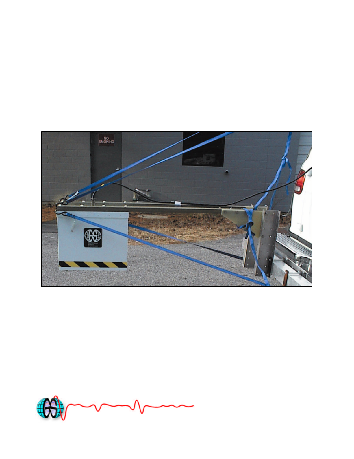
The Model 4108F antenna mounting hardware includes 2 square fiberglass tubes and 2 gusset
plates. Figure 1 shows a typical 4108 setup on the back of GSSI’s van.
Figure 1: Typical Model 4108F setup showing fiberglass rods and gusset plates.
The vertical metal pieces attached to the gusset plates are sold separately.
It is recommended that the user follow the following specifications for mounting the
4108F antennas:
(1) Recommended antenna bottom height above pavement with vehicle stationary: 18-20”
(46 – 51 cm)
(2) Recommended closest distance between antenna and significant metal (vertical metal
rods or the vehicle’s bumper) should be at least 40” (1 m).
(3) Black transducer cable should be fastened to one of fiberglass rails to prevent cable
movement.
(4) Excessive antenna bouncing should be minimized. The GSSI van setup includes 4
adjustable straps that minimize vertical and horizontal antenna movement, especially on
bumpy roads.
MN34-550 Rev A

Geophysical Survey Systems, Inc. Model 4108F Antenna
3
System Set tings and User’s Notes
Data Collection Recommendations:
The following software settings are recommended for general Model 4108F data collection.
See the SIR-20 manual for instructions on how to make setting modifications.
Table 1. Recommended data collection settings for Model 4108 antenna.
SIR-20
Transmit Rate 100 KHz
Samples/Scan 512
Scans/Sec: 160
Time Range 20 ns
Bits/Sample 16
Vertical Filter Settings:
IIR High Pass 1 MHz
FIR High Pass 250 MHz
FIR Low Pass 3000 MHz
Position: Signal position should be adjusted so that the latest arriving wavelet of the directcoupling is near the top of the scan. This wavelet should always be visible in the data. GSSI’s
post-processing software requires the presence of this wavelet in the data. Figure 2 shows a
typical scan of data with the signal properly positioned.
Direct-coupling waveform
Pavement surface reflection
Figure 2: Typical data scan obtained with Model 4108F and recommended software settings.
MN34-550 Rev A

Geophysical Survey Systems, Inc. Model 4108F Antenna
4
System Set tings and User’s Notes
Gain: Data collection gain fo r the 4108F antenna should be adjusted so that the peak amplitude
of the pavement surface reflection is approximately 2/3 of the total screen width. For example, in
Figure 2 the pavement surface reflection has an amplitude of approximately 20000 and the full
screen width is 32000. Using the filter settings described in Table 1, a gain of 13-14 dB is typical
for most pavement surfaces. However, for more highly reflective surfaces, such as concrete, the
user may have to decrease the gain value. It is very important that the pavement surface
reflection amplitude (and metal plate reflection when performing calibration) never reach
its maximum. Figure 3 shows an improperly gained signal.
Figure 3: Example of Model 4108F data scan collected with too much gain.
MN34-550 Rev A

Geophysical Survey Systems, Inc. Model 4108F Antenna
5
Attachment location of
System Set tings and User’s Notes
Quick Setup Procedure SIR-20
1. Connect the transducer cable from the SIR-20 (Channel 1) to the Model 4108F antenna.
2. Connect the power supply to the SIR-20.
3. Connect the Model 10F marker cable to the marker connector on the SIR-20, shown in
Figure 4. The SIR-20 will not operate with a horn antenna without this cable attached.
Model 10F
marker/transmit switch
Figure 3. Location of attachment of Model 10F marker/transmit switch cable.
4. Turn on the SIR-20 and wait until it is booted-up.
5. Double-click on the SIR-20 Desktop shortcut.
6. Press to recall a saved project for the Model 4108F antenna.
• First time users may want to select the “1GHz Horn Free Run” project from the folder
“Fixed SIR-20 Setups.”
7. Press to run the project. Be sure to keep the red “trigger” pressed on the handle of the
model 10F marker/transmit switch cable as shown in Figure 4. If the red trigger is released at
any time during data collection, data collection will be paused after 2 seconds and the data
file will be closed after 10 seconds.
MN34-550 Rev A

Geophysical Survey Systems, Inc. Model 4108F Antenna
6
The red transmit
and data collection
System Set tings and User’s Notes
trigger on the Model
10F cable must be
pressed at all times
during project setup
Figure 4. The red trigger on the Model 10F handle must be pressed at all times during project
setup and data collection using a horn antenna.
8. The position of the signal may be shifted and the data collection settings may be slightly
different than those currently recommended. Change the signal position if necessary so that it
is similar to the signal position shown in Figure 1.
• Compare all of the settings listed in Table 1 to those on the SIR-20 and make any
necessary adjustments prior to collecting data.
• Also check the gain of the signal to make sure it is not clipping. Save any changes made
to the signal position and signal gain to a new macro prior to collecting data.
MN34-550 Rev A
 Loading...