

Page 1

MicroEel
Solid Analog Streamer
P/N 60101-13 Rev. C
May 6, 2012
Operation Manual
GEOMETRICS, INC.
2190 Fortune Drive
San Jose, CA 95131 USA
Tel: (408) 954-0522
Fax: (408) 954-0902
www.geometrics.com
COPYRIGHT © 2011, 2012
Page 2

Table of Contents
1 – INTRODUCTION....................................................................................................... 4
2 – SYSTEM COMPONENTS........................................................................................ 5
2.1 C
ABLE.................................................................................................................. 5
2.1.1 Hydrophones............................................................................................... 7
2.1.2 Hydrophone Preamplifiers.......................................................................... 7
2.1.3 Deck and Tow Cable Connector Terminations........................................... 7
2.1.4 Cable Crate................................................................................................. 9
2.2 P
OWER SUPPLY AND REQUIREMENTS ................................................................ 10
2.2.1 DHA-7/MicroEel Battery Pack.................................................................10
2.2.2 Power Consumption.................................................................................. 12
2.2.3 AC Battery Charger.................................................................................. 12
3 – SYSTEM SET-UP.................................................................................................... 13
3.1 I
3.2
3.3
NTERCONNECTIONS........................................................................................... 13
DEPLOYMENT .................................................................................................... 13
BATTERY CHARGING ......................................................................................... 14
4 – APPENDIX ............................................................................................................... 16
4.1 C
4.2 C
4.3 S
4.4 W
ONNECTOR WIRING ......................................................................................... 16
ALIBRATION..................................................................................................... 16
PECIFICATIONS ................................................................................................. 17
ARRANTY AND SERVICE ................................................................................. 18
MicroEel Solid Analog Streamer Operation Manual Page 2 of 18
Rev. C 050612 du
Page 3

List of Figures
Figure 1. MicroEel active section with solid flotation (green) and tow cable (black)....... 4
Figure 2. MicroEel solid analog streamer block diagram.................................................. 6
Figure 3.
Figure 4. Deck cable 55-socket connector termination. .................................................... 8
Figure 5. Tow cable 55-pin connector termination shown with Kellems grip. ................. 9
Figure 6. Crate for transport, storage, and deployment. .................................................. 10
Figure 7. DHA-7/MicroEel Battery Pack. ....................................................................... 11
Figure 8. Detail of DHA-7/MicroEel Battery Pack. ........................................................ 11
Figure 9. Sheet lead, tin snips, and Bulldog tape............................................................. 14
Figure 10. DHA-7/MicroEel-D Battery Pack wiring....................................................... 16
Topside deck cable connector terminations (NK-27 termination not shown).... 8
MicroEel Solid Analog Streamer Operation Manual Page 3 of 18
Rev. C 050612 du
Page 4
1 – Introduction
The MicroEel Solid Analog Streamer is designed for high-resolution marine seismic
imaging. It is ideal for shallow oil and gas investigations, stratigraphic and structural
mapping, and teaching and research.
The MicroEel features solid-type construction specifically designed to withstand the
harsh conditions of commercial marine surveys. The active section is built using
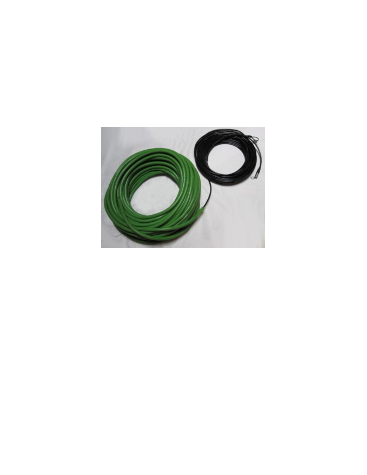
Geometrics continuous-flotation molding method (Figure 1).
Figure 1. MicroEel active section with solid flotation (green) and tow cable (black).
In addition, the MicroEel uses unique proprietary polymer hydrophones, which unlike
ceramic hydrophones are non-shattering. Polymer hydrophones provide superior
durability and performance under the rigors of marine applications with a stable signal
response up to 10 kHz.
Depending on your location, the MicroEel may require a US Department of Commerce
license for export.
This manual provides operating instructions, including description of the MicroEel
system components, setup, calibration, and warranty.
MicroEel Solid Analog Streamer Operation Manual Page 4 of 18
Rev. C 050612 du
Page 5

2 – System Components
The standard MicroEel Solid Analog Streamer system includes the following items:
Active section cable with tow cable, tail and eye bolt, and deck cable, coiled in a
plastic crate
DHA-7/MicroEel Battery Pack
Universal AC battery charger for the DHA-7/MicroEel Battery Pack
CD with support documents (*.pdf) including the operations manual, connector
wiring tables, and hydrophone calibration plots
2.1 Cable
The active section consists of a series of hydrophone groups, with the number of groups
equal to the number of channels, either 12 or 24 as a standard; other channel counts are
available through custom order. The available group intervals are a minimum of 1 m and
a maximum of 6.25 m in length. For group intervals between 3.125 and 6.25 m, there are
three depth-limited hydrophones spaced 0.11 m apart (0.22 m aperture) with the signal
summed electrically and connected to a preamplifier. For hydrophone groups less than
3.125 m, there is one hydrophone per group connected to a preamplifier. Other
hydrophone counts per group are available through custom order. All of the components
are in-line molded to a multi-conductor cable with a polyurethane jacket and Kevlar
center stress core; this is further encased in Geometrics’ proprietary solid flotation
material.
The tow, active section, and tail cables are all one integrated piece, with no
interconnections in between. The tow cable connects to a topside deck cable. The deck
and tow cables are terminated with mating waterproof connectors. The opposite end of
the deck cable is finished with a Y-type termination to connect to the DHA-7/MicroEel
Battery Pack and seismograph. The total maximum length of the streamer from head of
the deck cable to tail of the active section is 400 m.
MicroEel Solid Analog Streamer Operation Manual Page 5 of 18
Rev. C 050612 du
Page 6
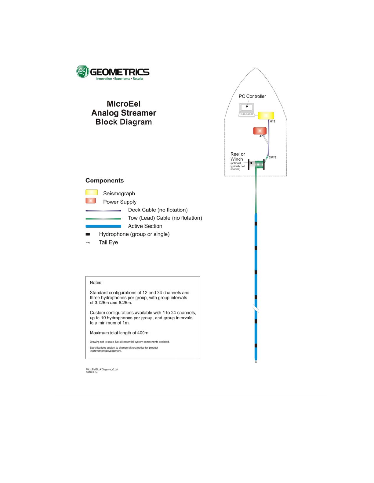
Figure 2. MicroEel solid analog streamer block diagram.
MicroEel Solid Analog Streamer Operation Manual Page 6 of 18
Rev. C 050612 du
Page 7

2.1.1 Hydrophones
The streamer uses Geometrics’ unique proprietary polymer hydrophones. The
hydrophone incorporates design features offering superior performance compared to
previous polymer hydrophone designs as well as the traditional PZT ceramic-type
hydrophones.
Specifically, it is non-shattering and incorporates an isolating platform,
making it immune to cable-borne energy. In addition, other design aspects allow its
response to acoustic pressure alone to dominate the output.
The hydrophones are depth-limited and become inoperable at depths greater than 30 ±5
m. The inoperable state is temporary and functionality fully recovers when the depth is
reduced. This limitation allows the MicroEel to be exported under less strict US
Department of Commerce laws.
2.1.2 Hydrophone Preamplifiers
The true differential preamplifier used with the hydrophone is of a single-pole low-cut
and a single pole high-cut design. The low-cut frequency is determined by the ½π RC
time constant which is related to the element capacitance and the input resistance of the
preamplifier front-end. The preamplifier features exceptionally low noise. Nominal
element capacitance is 7.2 nF at 22 degrees C. The design also provides full voltage
regulation at each preamplifier. The voltage regulator isolates each channel from the
other which is desired when all preamplifiers share a common power bus.
2.1.3 Deck and Tow Cable Connector Terminations
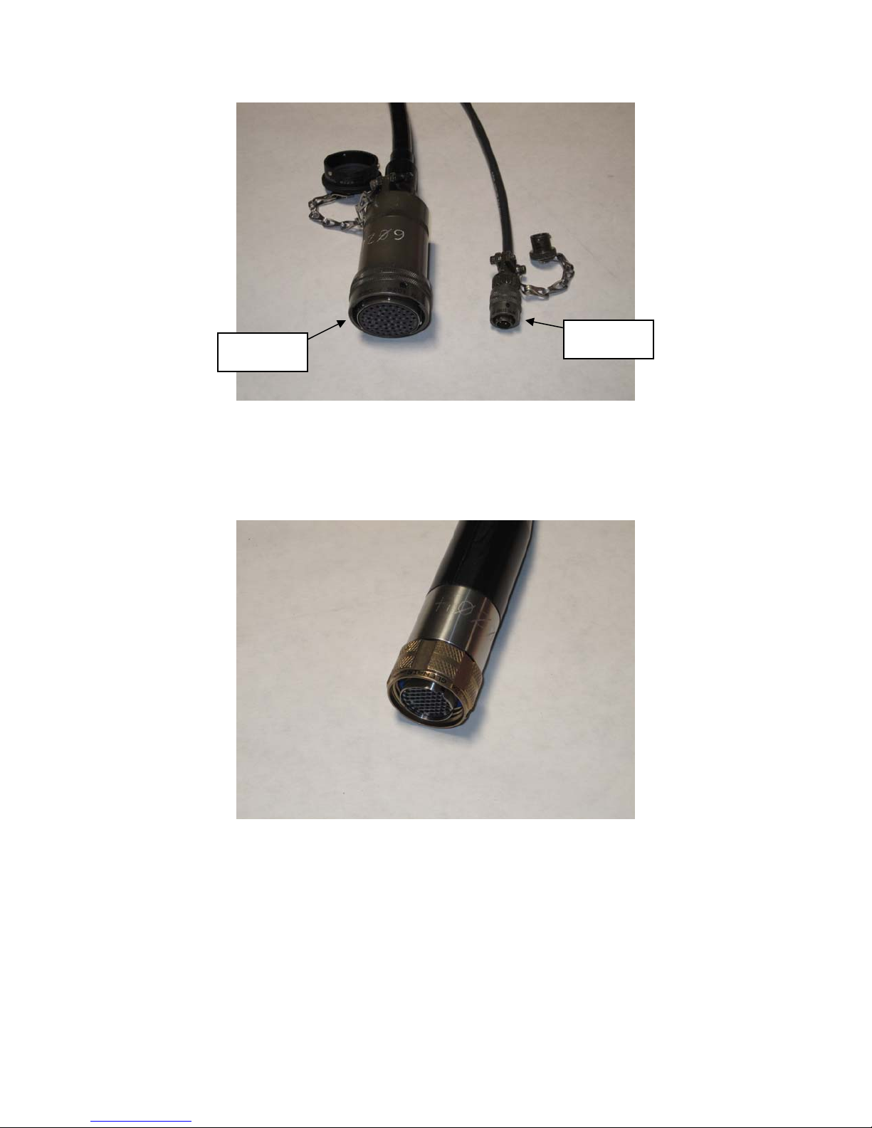
The standard topside deck cable termination is a Y-type with one 61-socket connector
(PT06J-24-61S) for analog output, and one 4-pin connector [PT06A-8-4P(SR)] for power
connection to the DHA-7/MicroEel Battery Pack (Figure 3). As an option, the analog
output termination may be ordered with a 27-socket connector(s) (NK-27-21C) instead of
the 61-socket connector. Adaptor cables are also available to connect to seismographs
with other analog input connector types.
MicroEel Solid Analog Streamer Operation Manual Page 7 of 18
Rev. C 050612 du
Page 8
r
r
61-socket
connecto
4-pin
connecto
Figure 3. Topside deck cable connector terminations (NK-27 termination not shown).
The standard deck cable termination for analog input from the tow cable is one 55-socket
waterproof connector (Glenair 220-06E16-55SN) (Figure 4).
Figure 4. Deck cable 55-socket connector termination.
MicroEel Solid Analog Streamer Operation Manual Page 8 of 18
Rev. C 050612 du
Page 9
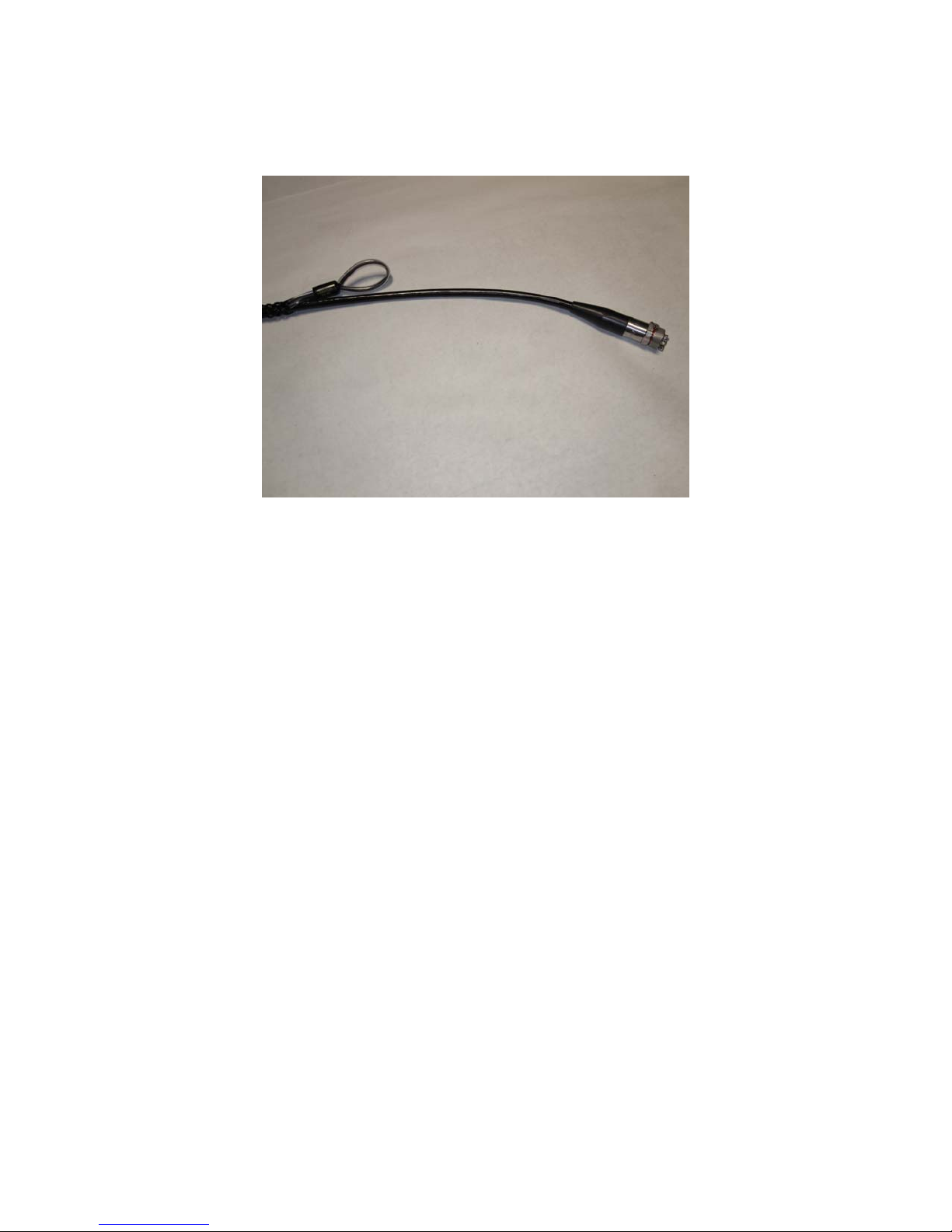
The standard tow cable termination for analog output to the deck cable is one 55-pin
waterproof connector (Glenair 220-01E16-55PN) (Figure 5).
Figure 5. Tow cable 55-pin connector termination shown with Kellems grip.
The connector pair between the deck and tow cables feature red marks on their collars to
indicate when pin and socket are aligned.
2.1.4 Cable Crate
The streamer is shipped coiled in a crate for storage, transport, and deployment (Figure
6). The crate is fully composed of inorganic plastic to comply with international shipping
regulations.
MicroEel Solid Analog Streamer Operation Manual Page 9 of 18
Rev. C 050612 du
Page 10
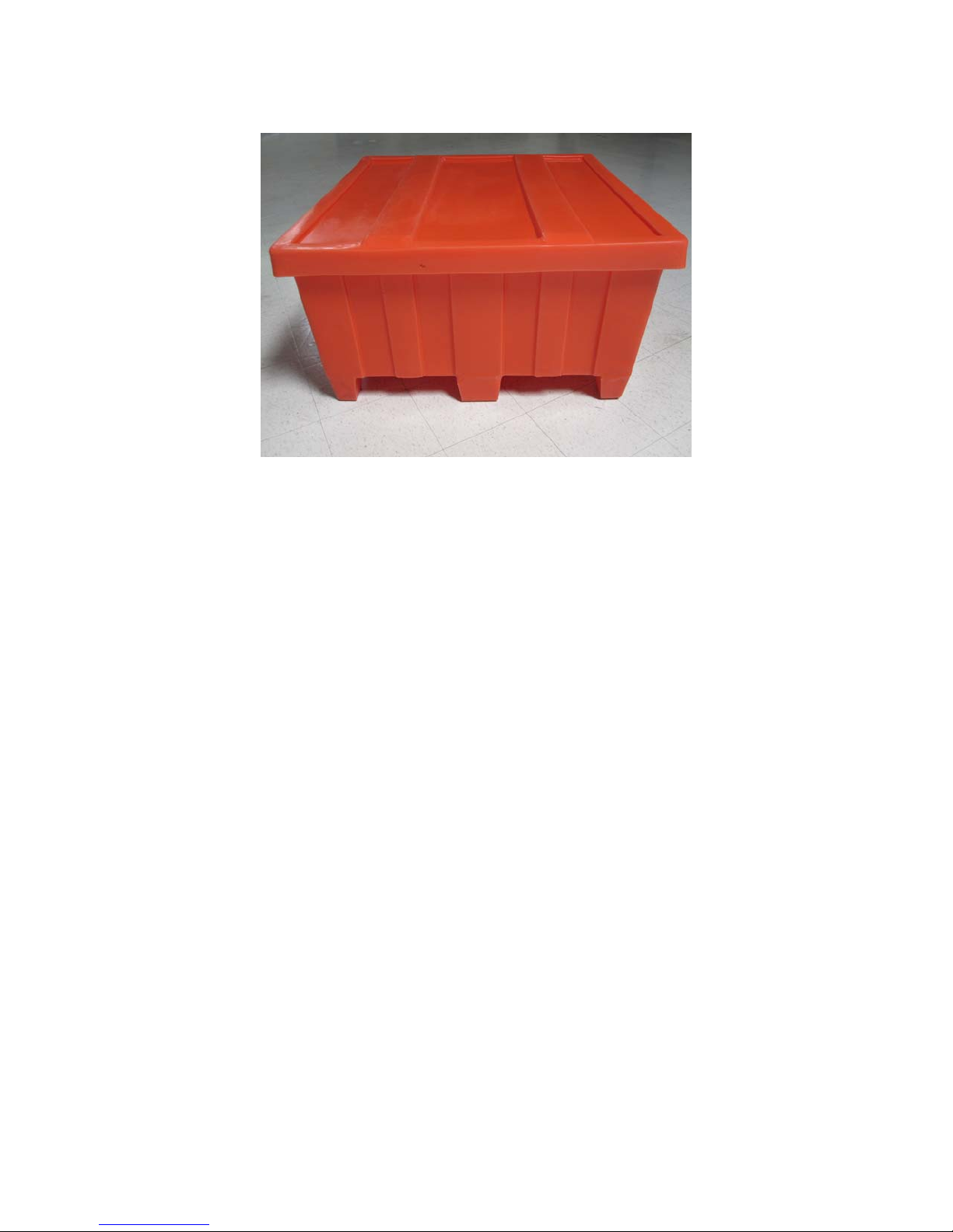
Figure 6. Crate for transport, storage, and deployment.
2.2 Power Supply and Requirements
The streamer is powered by the DHA-7/MicroEel Battery Pack. The battery pack is
rechargeable using the included AC battery charger.
2.2.1 DHA-7/MicroEel Battery Pack
The DHA-7/MicroEel Battery Pack (Figure 7) contains two 12V DC deep discharge (5
Amp-hour) sealed lead-acid batteries used in a ±12V DC differential power
configuration. The deck cable power lead is connected to the battery pack via the 4socket connector located on the right-hand side of the battery pack. This connector is also
used to connect the AC battery charger. Next to the connector is a grounding post (¼”-20
bolt and nut).
MicroEel Solid Analog Streamer Operation Manual Page 10 of 18
Rev. C 050612 du
Page 11
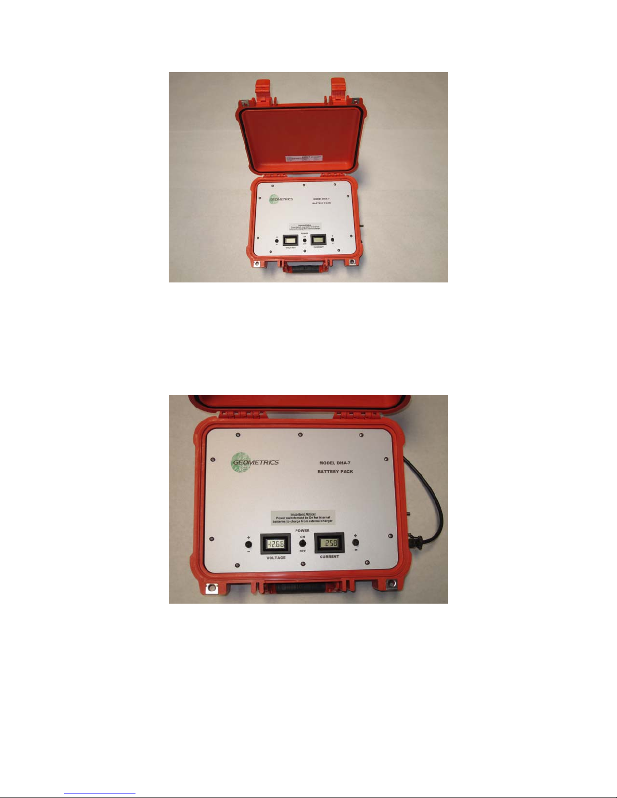
Figure 7. DHA-7/MicroEel Battery Pack.
The battery pack front panel includes a Power ON/OFF switch, a VOLTAGE (Volts)
meter, a CURRENT (Amps) meter with the associated +/- polarity switches for each
respective meter (Figure 8). The metering provides a method of measuring the individual
battery voltage and current being supplied to the streamer.
Figure 8. Detail of DHA-7/MicroEel Battery Pack.
The MicroEel is designed to be powered by the DHA-7/MicroEel Battery Pack; use of
another power source is not advised and could damage the streamer and void the
warranty. In addition, under no circumstances should power to the streamer be shared
with another instrument.
MicroEel Solid Analog Streamer Operation Manual Page 11 of 18
Rev. C 050612 du
Page 12

2.2.2 Power Consumption
Each hydrophone preamplifier draws approximately ±10.8 mA per channel. Based on
this draw, a 12-channel streamer with 6.25 m group interval has a total current of
approximately 130 mA, and a 24-channel streamer with 6.25 m group interval has a total
current of approximately 260 mA. The battery pack, with two 5 Amp-hour batteries,
should have sufficient capacity to power the streamer for the desired length of time. If
the batteries are fully charged, a 24-channel streamer can be powered continuously for
approximately 19 hours (5 Amp-hours divided by 260 mA).
The actual operating time will vary depending on the state, temperature, and age of the
batteries. The ideal battery operation temperature is between 41 to 77 degrees F (5 to 25
degrees C). Long-term exposure to temperatures above 106 degrees F (41 degrees C) can
shorten the life of the batteries. As temperature decreases, the available battery capacity
and performance are reduced; however, this is not a permanent condition and capacity
will be recovered as temperature rises.
2.2.3 AC Battery Charger
The AC battery charger is suitable for use anywhere in the world with a universal input
from 90V AC to 264V AC. The output is 1.5 Amps constant current at 24V DC.
Depending on the recharging mode of the charger and the state of the batteries, output
levels will vary.
MicroEel Solid Analog Streamer Operation Manual Page 12 of 18
Rev. C 050612 du
Page 13

3 – System Set-up
3.1 Interconnections
The procedure for setting up the MicroEel, DHA-7/MicroEel Battery Pack, and
seismograph interconnections is as follows.
1) With the battery pack power switch in the OFF position, connect the deck cable to
the tow cable and the 4-pin power connector on the deck cable to the 4-socket
power connector on the battery pack.
2) Move the battery pack power switch to the ON position. The CURRENT and
VOLTAGE meters will turn on and indicate the status of the batteries.
Toggle the +/- switch next to the CURRENT meter to measure the battery draw
for each polarity. Each current measurement should read approximately 130 mA
for a 12-channel streamer and 260 mA for a 24-channel streamer.
Next, toggle the +/- switch next to the VOLTAGE meter to measure the battery
potential for each polarity. The voltage should read from 11.8V DC to 13.4V DC
for each battery.
approximately 10.8V DC depending in the length of the cable lead. Recharge the
battery pack (see Section 3.3) immediately when the minimum permissible
voltage is reached.
3) Connect the analog output connector on the deck cable to the seismograph and
check for incoming signal. It is also recommended that the seismograph gain be
set to the lowest possible setting.
For ideal testing conditions allowing optimal hydrophone response, it is
recommended that the streamer be in water with no direct contact with any solid
surface, such as the ground, other parts of the cable, etc.
The streamer will operate with a minimum voltage of
3.2 Deployment
Most MicroEel streamers are easily deployed by hand or a small winch may be desired.
Avoid rubbing the tow cable jacket and active section flotation material on sharp or rough
edges.
The MicroEel is designed to be neutrally buoyant in fresh water. Depending on the water
salinity, weight may need to be added to the streamer. This is easily done with sheet lead
(Ames 4#, 4 by 36 by 1/16-inches thick, or similar) and brown friction seawater
(Bulldog) tape (2-inches thick, or similar) (Figure 9). If it is determined that the streamer
is too buoyant, at a minimum, weight should be added at the head, middle, and tail of the
active section. Simply use tin snips to cut sections of lead sheet to wrap around the
MicroEel Solid Analog Streamer Operation Manual Page 13 of 18
Rev. C 050612 du
Page 14
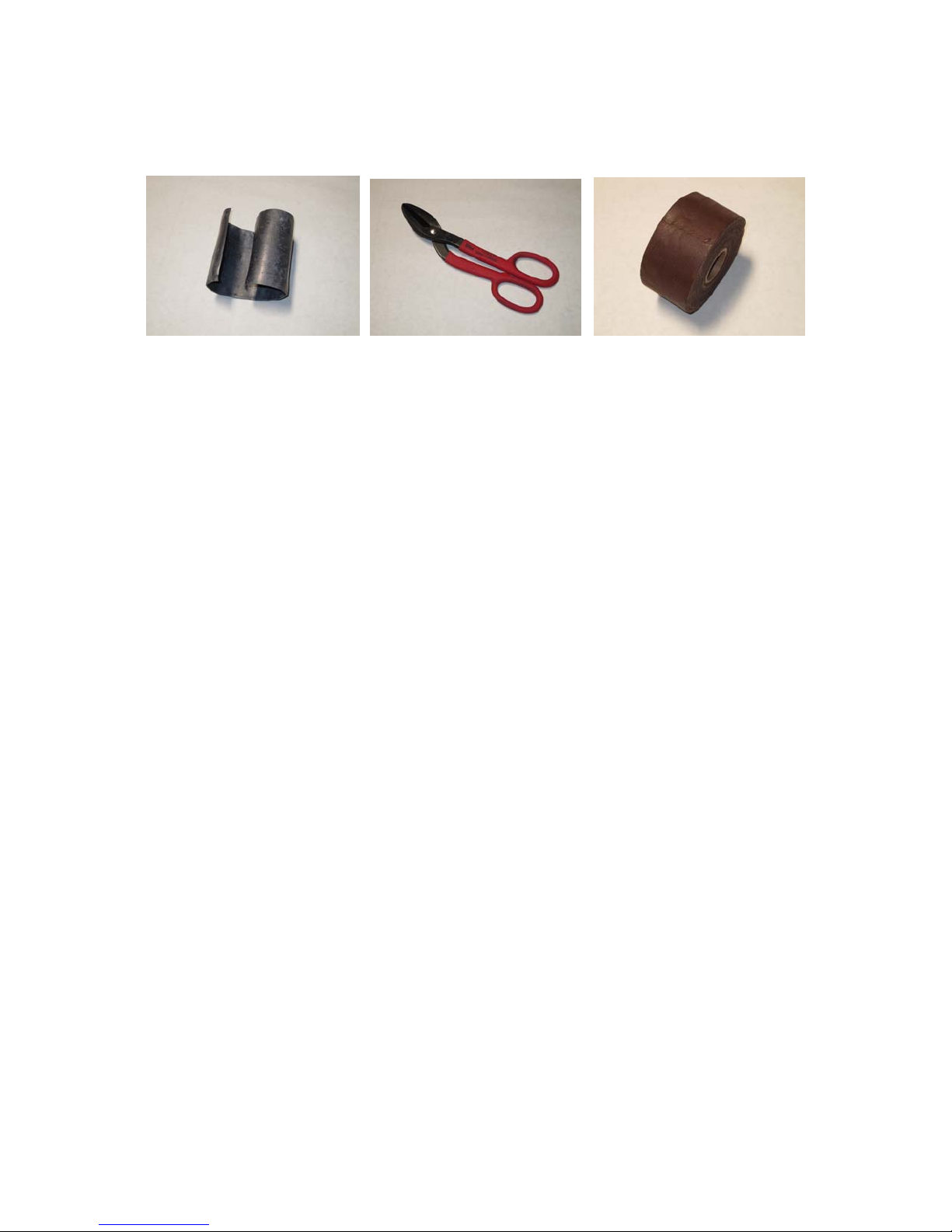
streamer; secure by wrapping with Bulldog tape.
Figure 9. Sheet lead, tin snips, and Bulldog tape.
3.3 Battery Charging
A new DHA-7/MicroEel Battery Pack should be charged for a minimum of 20 hours
prior to use. In addition, the temperature when the charging occurs should be between 41
to 77 degrees F (5 to 25 degrees C). If charging takes place above 77 degrees F (25
degrees C), the time required for a full charge will increase and the potential recharge
cycles will be reduced.
The procedure for charging the battery pack is as follows.
1) Plug the battery charger into an AC outlet and connect the 4-pin connector on the
charger cable to the 4-socket connector on the battery pack. Open the battery
pack enclosure vent located between the case latches to allow gas venting during
the charge cycle.
2) Switch the battery pack power switch to the ON position (the power switch must
be ON to charge the internal batteries from the external charger). The VOLTAGE
and CURRENT meters will turn on and indicate the status of the batteries.
3) The charger changes the recharging mode based on the state of the batteries, as
well, the values of the VOLTAGE and CURRENT meters will vary depending on
the cycle mode of the charger. There is an LED on the charger to indicate
charging status.
A lit LED indicates that the charger has power and is properly functioning.
An orange LED indicates that the charger is in charging mode with a constant
current of approximately 1.5 Amps.
A flashing LED indicates that the charger is in deep-discharge charging pulse
mode and charging starts at 0.5V DC, giving pulse currents up to 5V DC. This
has the effect of removing loose sulphation formed during the deep-discharge
MicroEel Solid Analog Streamer Operation Manual Page 14 of 18
Rev. C 050612 du
Page 15

state of the batteries.
A green LED indicates that the charger is in standby mode and the current slowly
reduces to zero.
Recharge the battery pack after every 6 to 8 hours of use. It will not be harmed if left on
a continuous charge past the normal recharge time; however, continuous charging for
extended periods of time will reduce the life of the batteries. Therefore, it is
recommended that a continuous charge be limited to no more than 1 week.
The battery pack will lose capacity without use. A battery pack in storage must be
recharged at least every 6 months or sulphation will reduce the storage capacity.
Depending on the charging, depth of discharge, and use conditions, the expected number
of recharge cycles is usually between 500 and 1000.
MicroEel Solid Analog Streamer Operation Manual Page 15 of 18
Rev. C 050612 du
Page 16
4 – Appendix
4.1 Connector Wiring
Wiring tables for the deck and tow cables are included on the serialized CD included with
each shipment. Channel 1 is always wired as the first hydrophone/hydrophone group in
the active section.
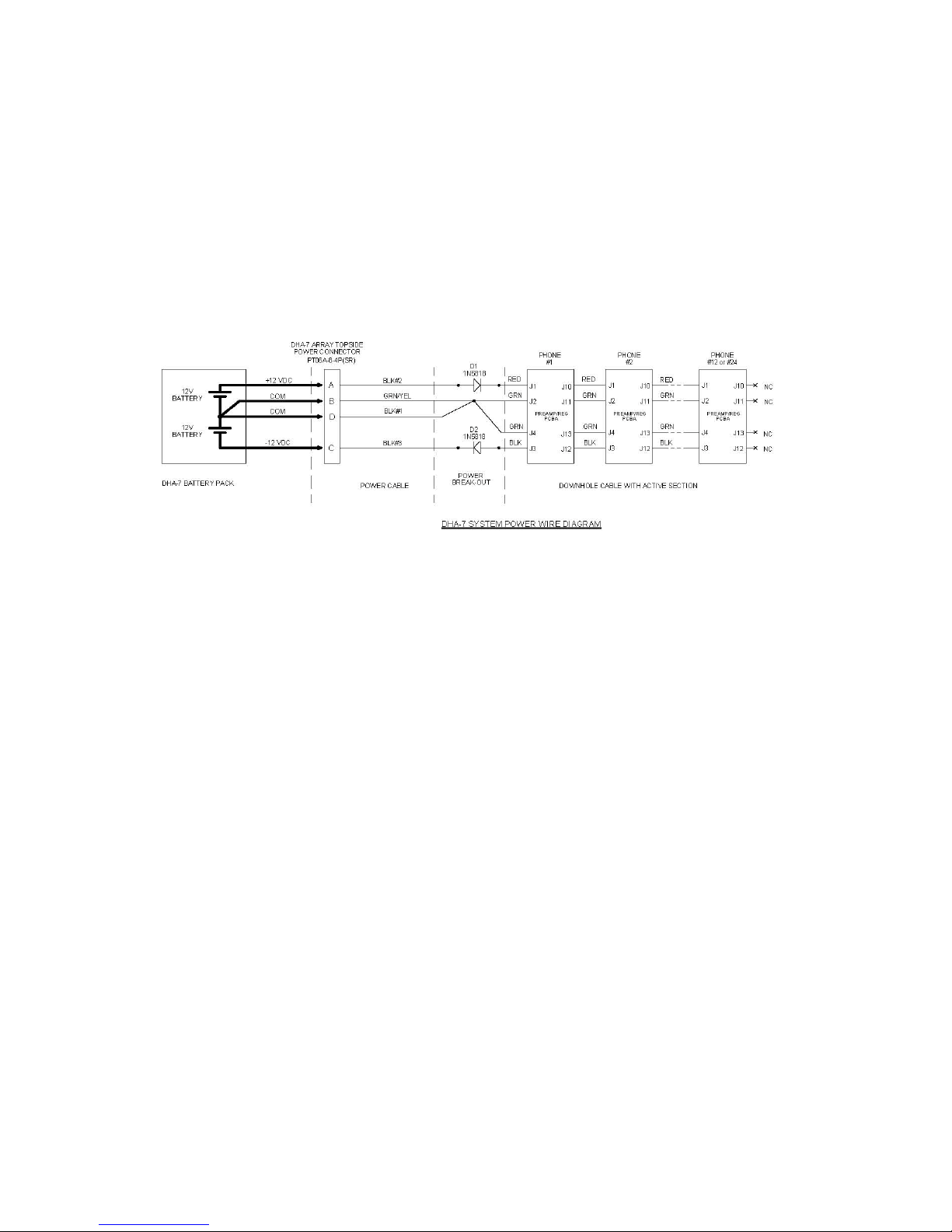
Figure 10 shows the battery pack-to-streamer wiring.
Figure 10. DHA-7/MicroEel-D Battery Pack wiring.
4.2 Calibration
All hydrophone channels of any given streamer have been low-frequency calibrated over
a band from 0 to 200 Hz as a quality control measurement. The performance band
defined by the low-cut of the polymer film capacitance and input resistance of 10 Hz, and
a high-cut of 10 kHz has been demonstrated to be “predictably flat” over a entire band.
Significant testing has demonstrated that the low frequency calibration of the hydrophone
is 99.99% representative of the broadband response up to 10 kHz. This low frequency
calibration is performed by the substitution method where a known calibrated reference is
compared with the unknown hydrophone channel under calibration. The calibrated
reference and the unknown are placed in a sealed chamber into which white noise is
injected. A dual channel FFT analyzer is used to compare the response of the two and the
resulting transfer function indicates the response in dB of the unknown in terms of
sensitivity relative to 1V per µPa and phase.
All hydrophone channels in the streamer are guaranteed to be within a ±1 dB relative
span. The calibration plots for each hydrophone are provided on the serialized CD
included with each shipment.
MicroEel Solid Analog Streamer Operation Manual Page 16 of 18
Rev. C 050612 du
Page 17

4.3 Specifications
Hydrophone
Sensor Type Proprietary Polymer
Frequency Response 10 Hz to 10,000 Hz ±1.0 dB
Capacitance 7.2 nF per element at 22° C
Sensitivity (Nominal) -196 dB re 1 Volt per 1 µPa
Sensitivity to Acceleration < -70 dB re 1 Volt per g
Operating Depth (Maximum) 30 ±5 m
Preamplifier
Type Ultra-low noise differential
Gain 6 dB
Low Corner Frequency -3 dB at 10Hz
Current 11mA per channel
Power ±12 V DC DHA-7/MicroEel Battery Pack (topside)
Active Section
Channels 12 or 24; other counts available*
Hydrophones per Group 1 or 3; other counts available*
Group Aperture 0 or 0.22 m; up to 1 m maximum*
Group Interval 3.125 m or 6.25 m; other intervals available to 1 m minimum*
Flotation Material Polyurethane-based
Outside Diameter 32 mm
Weight (in air) 0.79 kg/m
Bend Radius 0.46 m
Strength Member Kevlar center stress core
Working Load 182 kg
Breaking Strength 909 kg
Deck and Tow Cables
Type Multi-conductor with polyurethane jacket
Length (Maximum Total) 400 m (including active section)
Termination Deck: Y-type with one 61-socket connector (or 27-socket connector),
Outside Diameter 13.5 mm
Weight 0.15 kg/m
Bend Radius 0.46 m
Strength Member Kevlar center stress core
Working Load 182 kg
Breaking Strength 909 kg
Temperature
Operating Range -10°C to +60°C
Storage Range -40°C to +60°C
*Please contact the factory to discuss your requirements.
one 4 pin connector (topside); one 55-socket waterproof connector
Tow: one 55-pin waterproof connector
MicroEel Solid Analog Streamer Operation Manual Page 17 of 18
Rev. C 050612 du
Page 18

4.4 Warranty and Service
Geometrics warrants the MicroEel system for 6 months. Warranties commence on the
date of shipment. If the equipment fails during the applicable warranty period,
Geometrics will repair or replace the defective item at its factory in San Jose, California
at no charge to the customer for parts and labor. The cost to ship the equipment to
Geometrics' factory and back to the customer's site is for the customer's account. Repairs
might be done at a local service center, if available, nearest the customer’s location.
Geometrics must be notified within 7 days of system failure for any warranty claim.
Geometrics must establish to its satisfaction that failures have not been the result of abuse
or improper deployment of the system. Warranties are void for damage caused by
incorrectly applying power, including over-voltage and reverse voltage.
The limited warranty stated herein is in lieu of all other warranties expressed or implied
(including the implied warranties of merchantability and fitness for a particular purpose)
and of all other obligations or liability on the part of Geometrics, and Geometrics neither
assumes nor authorizes any person to assume for it any other liability. Geometrics shall
not be liable for special, incidental, or consequential damages of any nature (including,
but not limited to lost revenue or profits) with respect to any merchandise or services
sold, delivered or rendered hereunder.
Should the instrument or any part thereof need to be returned to the factory for servicing,
please contact the Customer Service Department via email at
telephone at 408-954-0522. Be ready to provide the serial number, which may be found
on the tow cable connector collar, and an explanation of the problem. You will be issued
an RMA number and instructions for shipping the instrument.
MicroEel Solid Analog Streamer Operation Manual Page 18 of 18
Rev. C 050612 du
 Loading...