


Model 4200 Series
Vibrating Wire Strain Gauges
Instruction Manual
©2018, GEOKON. All rights reserved.
Document Revision: BB | Release date: 12/4/18


WARRANTY STATEMENT
GEOKON warrants its products to be free of defects in materials and workmanship,
under normal use and service for a period of 13 months from date of purchase. If the
unit should malfunction, it must be returned to the factory for evaluation, freight
prepaid. Upon examination by
repaired or replaced at no charge. However, the
evidence of having been tampered with or shows evidence of being damaged as a
result of excessive corrosion or current, heat, moisture or vibration, improper specification, misapplication, misuse or other operating conditions outside of
control. Components that wear or are damaged by misuse are not warranted. This
includes fuses and batteries.
GEOKON manufactures scientific instruments whose misuse is potentially dangerous.
The instruments are intended to be installed and used only by qualified personnel.
There are no warranties except as stated herein. There are no other warranties,
expressed or implied, including but not limited to the implied warranties of merchantability and of fitness for a particular purpose.
damages or losses caused to other equipment, whether direct, indirect, incidental,
special or consequential which the purchaser may experience as a result of the installation or use of the product. The buyer’s sole remedy for any breach of this agreement
by GEOKON or any breach of any warranty by GEOKON shall not exceed the purchase
price paid by the purchaser to
affected by such breach. Under no circumstances will
claimant for loss incurred in removing and/or reinstalling equipment.
GEOKON, if the unit is found to be defective, it will be
WARRANTY IS VOID if the unit shows
GEOKON’s
GEOKON is not responsible for any
GEOKON for the unit or units, or equipment directly
GEOKON reimburse the
Every precaution for accuracy has been taken in the preparation of manuals and/or
software, however,
GEOKON neither assumes responsibility for any omissions or
errors that may appear nor assumes liability for any damages or losses that result
from the use of the products in accordance with the information contained in the
manual or software.
No part of this instruction manual may be reproduced, by any means, without the written consent of GEOKON. The
information contained herein is believed to be accurate and reliable. However,
for errors, omissions or misinterpretation. The information herein is subject to change without notification.
GEOKON® wordmark and logo are registered trademarks with the United States Patent and Trademark Office.
The
GEOKON assumes no responsibility


TABLE OF CONTENTS
1. INTRODUCTION............................... ............................ ............................. ............................... .....................1
2. MODELS
.............................. ............................. ............................ ............................... ............................. .............2
2.1 MODELS 4200 AND 4200L ............................... ............................. ............................ ................2
2.2 MODELS 4200-6 AND 4200-7 ................................... ............................... ............................ ...3
2.3 MODEL 4202.................. ............................. ............................... ............................ ............................. .....3
2.4 MODEL 4210.................. ............................. ............................... ............................ ............................. .....4
3. PRIOR TO INSTALLATION......................... ............................. ............................ .............................5
3.1 ADJUSTING GAUGE TO THE DESIRED RANGE ................... ............................ ........5
3.2 GAUGE AND CABLE ASSEMBLY..................... ............................ ............................... ...........5
3.3 PRELIMINARY CHECK ................. ............................... ............................. ............................ ...........5
4. INSTALLING THE GAUGES IN CONCRETE................. ............................ .....................7
4.1 DIRECT ATTACHMENT TO REBAR........................................ ............................. ..................7
4.2 SUSPENSION METHOD ............ ............................ ............................. ............................... .............7
4.3 ALTERNATIVE SUSPENSION METHOD............................ ............................. ..................8
4.4 USING PRE-CAST BRIQUETTES, SHOTCRETE, OR GROUTING.............. ...9
4.5 CABLE SPLICING AND TERMINATION..................... ............................. ..........................9
4.6 LIGHTNING PROTECTION.... ............................. ............................... ............................ ................9
5. TAKING READINGS
.............................. ............................. ............................ ............................... ....... 11
5.1 MICRO-6000 DATALOGGER ............................. ............................... ............................. ......... 11
5.2 EMBEDMENT STRAIN GAUGE READOUT POSITIONS........................... ....... 11
5.3 GK-404 READOUT BOX..................... ............................... ............................ ............................. . 11
5.3.1 OPERATING THE GK-404 ...................................................... ............................ ......................... 12
5.4 GK-405 READOUT BOX..................... ............................... ............................ ............................. . 12
5.4.1 CONNECTING SENSORS WITH 10-PIN BULKH EAD CONNECTORS
ATTACHED
5.4.2 CONNECTING SENSORS WITH BARE LEADS........... ............................. ........................... 13
5.4.3 OPERATING THE GK-405 ...................................................... ............................ ......................... 13
.............................. ............................ ............................. ............................... ................. 13
5.5 GK-403 READOUT BOX (OBSOLETE MODEL) ........ ............................... ................. 14
5.5.1 CONNECTING SENSORS WITH 10-PIN BULKH EAD CONNECTORS
ATTACHED
5.5.2 CONNECTING SENSORS WITH BARE LEADS........... ............................. ........................... 14
5.5.3 OPERATING THE GK-403 ...................................................... ............................ ......................... 14
.............................. ............................ ............................. ............................... ................. 14
5.6 MEASURING TEMPERATURES ................................. ............................ .............................. 14
6. DATA REDUCTION ....... ............................. ............................... ............................. ............................ .... 15
I

6.1 READOUT BOX POSITION A .............................. ............................... ............................ ......... 15
6.2 READOUT BOX POSITION B....................... ............................... ............................. ................ 15
6.3 READOUT BOX POSITIONS D & E........... ............................... ............................ .............. 15
6.4 STRAIN RESOLUTION............ ............................. ............................... ............................ .............. 16
6.5 TEMPERATURE CORRECTIONS ......... ............................ ............................. ........................ 16
6.5.1 MODEL 4200-6 / 4200-7 CORRECTIONS....................... ............................ ........................... 17
6.6 SHRINKAGE EFFECTS...................... ............................. ............................ ............................... .... 17
6.7 CREEP EFFECTS .................................... ............................. ............................... ............................ .... 17
6.8 EFFECT OF AUTOGENOUS GROWTH................... ............................... ........................... 18
6.9 CONVERTING STRAIN TO LOAD......... ............................... ............................. ................... 18
6.10 EFFECTIVE MODULUS............. ............................. ............................... ............................ ......... 18
7. TROUBLESHOOTING........................ ............................ ............................. ............................... ........... 19
APPENDIX A. SPECIFICATIONS
............................... ............................ ............................. ........... 21
A.1 STRAIN GAUGE ........... ............................. ............................ ................................ ............................. 21
A.2 THERMISTOR . ............................ ................................ ............................ ............................. ................ 21
APPENDIX B. THEORY OF OPERATION
APPENDIX C. THERMISTOR TEMPERATURE DERIVATION
.............................. ............................. ................... 22
....................... 24
APPENDIX D. HIGH-TEMPERATURE THERMISTOR
LINEARIZATION
............................... ............................. ............................ .............. 25
APPENDIX E. NO STRESS STRAIN ENCLOSURE............................ ........................ 26
APPENDIX F. MODEL 4200HT-T HIGH-TEMPERATURE STRAIN
GAUGE
............................... ............................. ............................ ............................... ......... 28
APPENDIX G. MEASUREMENT AND CORRECTION OF
TEMPERATURE EFFECTS
............................. ............................. ................... 29
II

FIGURES
FIGURE 1: ON-SITE INSTALLATION PHOTO ....................................................................1
FIGURE 2: MODEL 4200 VIBRATING WIRE STRAIN GAUGE ......................................... 2
FIGURE 3: MODEL 4200L VIBRATING WIRE STRAIN GAUGE ....................................... 2
FIGURE 4: MODEL 4200-6 VIBRATING WIRE STRAIN GAUGE ...................................... 3
FIGURE 5: MODEL 4200-7 VIBRATING WIRE STRAIN GAUGE ...................................... 3
FIGURE 6: MODEL 4202 VIBRATING WIRE STRAIN GAUGE ......................................... 3
FIGURE 7: MODEL 4210 VIBRATING WIRE STRAIN GAUGE ......................................... 4
FIGURE 8: ADJUSTING THE RANGE OF THE STRAIN GAUGE .......................................5
FIGURE 9: ASSEMBLED STRAIN GAUGE AND COIL HOUSING ....................................5
FIGURE 10: ATTACHING GAUGES TO REBAR ................................................................. 7
FIGURE 11: SUSPENDING STRAIN GAUGES BETWEEN REBAR ...................................8
FIGURE 12: ALTERNATIVE METHOD FOR ATTACHING GAUGES TO REBAR ...............8
FIGURE 13: LIGHTNING PROTECTION SCHEME .......................................................... 10
FIGURE 14: GK-404 READOUT .......................................................................................12
FIGURE 15: LEMO CONNECTOR TO GK-404 ................................................................. 12
FIGURE 16: GK-405 READOUT .......................................................................................13
FIGURE 17: NO STRESS STRAIN ENCLOSURE .............................................................26
FIGURE 18: MODEL 4200HT-T ....................................................................................... 28
III

TABLE S
TABLE 1: HEAT SHRINK COLOR DESIGNATIONS...........................................................2
TABLE 2: EMBEDMENT STRAIN GAUGE DATALOGGER PARAMETERS .................... 11
TABLE 3: READOUT POSITIONS......................................................................................11
TABLE 4: EMBEDMENT STRAIN GAUGE FACTORS......................................................15
TABLE 5: STRAIN RESOLUTION ...................................................................................... 16
TABLE 6: EFFECTIVE MODULUS .....................................................................................18
TABLE 7: RESISTANCE WORK SHEET............................................................................20
TABLE 8: SAMPLE RESISTANCE .....................................................................................20
TABLE 9: STRAIN GAUGE SPECIFICATIONS..................................................................21
TABLE 10: EMBEDMENT STRAIN GAUGE THEORETICAL PARAMETERS .................22
TABLE 11: THERMISTOR RESISTANCE VERSUS TEMPERATURE ..............................24
TABLE 12: THERMISTOR RESISTANCE VERSUS TEMPERATURE FOR MODEL
4200HT ..........................................................................................................25
IV

EQUATIONS
EQUATION 1: PERIOD TO DIGITS CONVERSION........................................................... 15
EQUATION 2: THEORETICAL STRAIN ............................................................................. 15
EQUATION 3: APPARENT STRAIN...................................................................................15
EQUATION 4: CORRECTION FOR TEMPERATURE EFFECTS ON THE GAUGE............ 16
EQUATION 5: TRUE, LOAD-RELATED STRAIN CORRECTED FOR TEMPERATURE .... 16
EQUATION 6: ACTUAL STRAIN........................................................................................17
EQUATION 7: STRAIN TO LOAD FORMULA................................................................... 18
EQUATION 8: RESISTANCE TO TEMPERATURE ............................................................ 24
EQUATION 9: HIGH-TEMPERATURE RESISTANCE TO TEMPERATURE ...................... 25
EQUATION 10: TEMPERATURE-INDUCED STRESS ......................................................29
EQUATION 11: COMBINED TEMPERATURE AND LOAD-RELATED STRESS.............. 29
EQUATION 12: EXTERNAL LOAD STRESS...................................................................... 29
EQUATION 13: ACTUAL STRAIN .....................................................................................29
V

VI

1. INTRODUCTION
GEOKON vibrating wire embedment strain gauges are designed for direct
embedment in concrete. This can be accomplished by attaching the gauge to
rebar or tensioning cables and then casting the gauge into a concrete briquette,
which is subsequently cast into the structure, or grouting the gauge into
boreholes in the concrete.
Strains are measured using the vibrating wire principle. A length of steel wire is
tensioned between two end blocks that are firmly in contact with the mass
concrete. Deformations in the concrete will cause the two end blocks to move in
relation to each other, altering the tension in the steel wire. This change in
tension is measured as a change in the resonant frequency of vibration of the
wire.
Two coils, one with a magnet insert, the other with a pole piece insert, are
located close to the vibrating wire. In use, a pulse of varying frequency (swept
frequency) is applied to the coils causing the wire to vibrate primarily at its
resonant frequency.
Portable readouts and dataloggers are available from
GEOKON. These models,
when used in conjunction with vibrating wire strain gauges, will provide the
necessary voltage pulses to pluck the wire. During vibration, a sinusoidal signal
is induced in the coils and transmitted to the readout box where it is conditioned
and displayed.
This manual contains installation instructions, readout and data reduction
procedures, and troubleshooting guidelines.
Note: Do not rotate or pull on the gauge end blocks, because this will alter the
readings and may cause permanent damage.
FIGURE 1: On-site Installation Photo
MODEL 4200 SERIES STRAIN GAUGES | INTRODUCTION | 1

2. MODELS
GEOKON vibrating wire strain gauges come in a variety of models, all easily
identifiable by the color of heat shrink which covers the protective tubes, as
shown in the table below.*
Model Heat Shrink Color
4200 (4,000 Blue
4200L Black
4200
6 (5,000 Red
4200
7 (10,000 Green
4200X Yellow (dependent on the reason for the X designation)
*Applicable only to products manufactured after September 2016.
TABLE 1: Heat Shrink Color Designations
The following sections describe in brief the various embedment strain gauges
available from
2.1 MODELS 4200 AND 4200L
GEOKON Models 4200 and 4200L are designed primarily for long-term strain
measurements inside mass concrete, in structures such as foundations, piles,
bridges, dams, containment vessels, tunnel liners, etc.
The 4200L is a low-modulus version designed to enable early curing strains to
be measured. The length of the 4200 gauge is 152 mm (6”).
GEOKON.
FIGURE 2: Model 4200 Vibrating Wire Strain Gauge
FIGURE 3: Model 4200L Vibrating Wire Strain Gauge
2 | MODELS | GEOKON

2.2 MODELS 4200-6 AND 4200-7
Collar
Collar
Model 4200-6 and 4200-7 strain gauges are supplied fully sealed and pretensioned with the plucking coil mounted. Note the small collar under the shrink
tube at one end.
FIGURE 4: Model 4200-6 Vibrating Wire Strain Gauge
FIGURE 5: Model 4200-7 Vibrating Wire Strain Gauge
2.3 MODEL 4202
Model 4202 is designed for direct embedment in grout, mortar, and small
aggregate concrete. It is also useful for model studies. The length of the 4202
gauge is 50 mm (2”).
FIGURE 6: Model 4202 Vibrating Wire Strain Gauge
MODEL 4200 SERIES STRAIN GAUGES | MODELS | 3
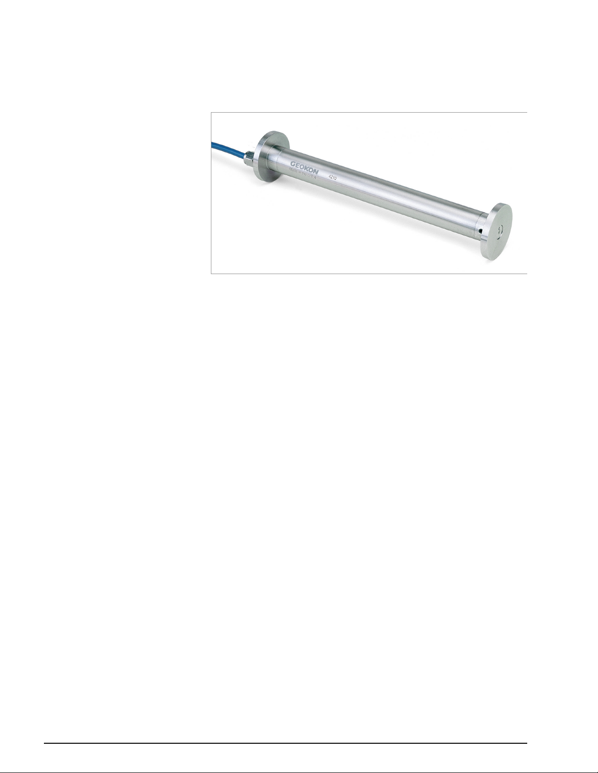
2.4 MODEL 4210
Model 4210 is designed for embedment in large aggregate concrete (greater
than 3/4 of an inch). The standard gauge length is 254 mm (10”), other gauge
lengths available include: Model 4212: 305 mm (12”), and Model 4214: 356 mm
(14”).
FIGURE 7: Model 4210 Vibrating Wire Strain Gauge
4 | MODELS | GEOKON

3. PRIOR TO INSTALLATION
Collar
3.1 ADJUSTING GAUGE TO THE DESIRED RANGE
GEOKON embedment strain gauges are supplied fully sealed and pretensioned.
Model 4200 gauges are normally supplied with the wire tension set near the
middle of their range. If the range needs to be adjusted for some reason, the
wire tension may be changed by the following procedure:
1. Attach the red and black leads to a readout box that has been set to position
D, reading in microstrain.
2. Grip the small collar under the shrink tube and rotate the end flange as
shown in the figure below.
3. Rotate clockwise to decrease the initial reading; rotate counterclockwise to
increase the reading. For example, if the gauge will see all compression, it
should be set to about 4000 microstrain.
FIGURE 8: Adjusting the Range of the Strain Gauge
Model 4200-6 / 4200-7 Note: Although the readings are taken on position D,
the digits shown must be converted to microstrain manually. To do this, multiply
the observed digit change by the gauge factor given on the calibration sheet
provided with the strain gauge.
3.2 GAUGE AND CABLE ASSEMBLY
Insert the flat part of the gauge into the slot in the coil assembly located at the
end of the cable. Slide the hose clamp over the assembly and tighten.
FIGURE 9: Assembled Gauge and Coil Housing
Alternatively, the coil housing can be glued in place using cyanoacrylate glue. If
this method is chosen, it will no longer be possible to remove the gauge from
the coil housing.
3.3 PRELIMINARY CHECK
A preliminary check should be performed before installing the gauge in the field.
To perform the preliminary check, complete the following steps:
1. Using an ohmmeter, check the resistance between the two lead wires
(usually red and black).
MODEL 4200 SERIES STRAIN GAUGES | PRIOR TO INSTALLATION | 5

For Models 4200, 4200L, 4200-6, 4200-7, and 4210/12/14 it should be
about 180 ohms.
For Model 4202, it should be about 50 ohms.
Remember to add the cable resistance at approximately 14.7/1000' or
48.5/km at 20 °C. Multiply these factors by two to account for both
directions.
2. Using an ohmmeter, check the resistance between the two thermistor wires
(usually white and green). Using Table 11 on page 24, convert the
resistance to temperature. Compare the result to the current ambient
temperature. (For Model 4200HT see Table 12 on page 25.)
3. Connect the gauge to a readout box. (See readout instructions, Section 5.)
Observe the displayed readout. The reading should be about the midrange
position as defined in Table 2 on page 11.
4. Press on the gauge ends and confirm that it makes the reading decrease.
Return any faulty gauges to the factory. Gauges should not be opened in the
field.
6 | PRIOR TO INSTALLATION | GEOKON

4. INSTALLING THE GAUGES IN CONCRETE
Nylon Cable Tie
Instrument Cable
4200
Coil Assembly
Wood or
Polystyrene
Block
Wire Tie
Wire Tie
Rebar or
Tensioned Cable
FIGURE 10: Attaching Gauges to Rebar
GEOKON strain gauges are typically set into concrete in one of two ways:
1. Cast the units directly into the concrete mix (see Sections 4.1 through 4.3)
2. Cast them into briquettes that are subsequently cast into the concrete
structure (see Section 4.4).
When casting the gauge directly into the concrete mix, take care to avoid
applying any large forces to the end blocks during installation. This is most
imperative when installing Model 4202 gauges.
Model 4202 Note: Do not wrap an iron tie wire around the body of the gauge;
doing so could cause damage due to its delicate construction. Instead, use the
holes in the end blocks to affix the gauge to the rebar, being sure that the gauge
is not tensioned or compressed in the longitudinal direction.
Model 4200L Note: This gauge is specifically designed to allow strains to be
measured in curing concrete. However, do not bury the gauge more than one
meter deep; doing so could damage the gauge.
4.1 DIRECT ATTACHMENT TO REBAR
1. Place two pieces of wood or polystyrene foam between the gauge and the
rebar as shown in Figure 10 on this page.
2. Use soft iron tie wire, similar to the kind that is normally used for tying rebar
cages together. Run the wire around the body of the strain gauge and
around the rebar. Twist the wire around itself to hold the gauge in place.
3. Tie the instrument cable off to the rebar using nylon cable ties.
Note: Don’t tie the wires too tightly, since rebar and tension cables tend to
move during concrete placement and vibration. Take care not to damage the
cable with the vibrator. The gauge can also be placed directly into the mix if it
can be assured that the orientation will be correct after the gauge placement.
4.2 SUSPENSION METHOD
1. Wrap a layer of self-vulcanizing rubber tape 3 cm from each gauge end, as
shown in Figure 11 on page 8.
Model 4210 Note: This step is not necessary
The layers of rubber serve as a shock absorber, dampening any vibration of
the suspension system. Without the rubber layers, the resonant frequency
of the tie wires might interfere with the resonant frequency of the gauge
when the tie wires are tightened. This can result in unstable readings, or in
no readings at all. However, this problem disappears once the concrete has
been placed.
For a method that avoids this potential problem, see Section 4.3.
2. Use soft iron tie wire, the kind normally used for tying rebar cages together.
Wrap the wire around the rubber strips twice.
3. Twist two loops in the wire, one on either side of the gauge, at a distance of
3 cm from the gauge body. Repeat this process at the other end.
4. Position the gauge between the rebar and twist the wire ends twice around
the rebar, then around itself.
5. Tighten the wire and orient the gauge by twisting the loops between the
gauge and the rebar.
MODEL 4200 SERIES STRAIN GAUGES | INSTALLING THE GAUGES IN CONCRETE | 7

6. Attach the plucking coil using a hose clamp. Tie the instrument cable off to
Instrument Cable
Coil Assembly
Rebar or
Tensioned Cable
Wire Tie
Wire Tie
Rubber Tape
4200
Wire Tie
Wire Tie
Rubber Tape
Nylon Cable Tie
Instrument Cable
Short Lengths
of Rebar
Nylon Cable Ties
Nylon Cable Ties
Nylon Cable Ties
one of the rebar using nylon cable ties.
FIGURE 11: Suspending Model 4200/4200L/4200HT Strain Gauges Between Rebar
4.3 ALTERNATIVE SUSPENSION METHOD
Tie two short pieces of steel rebar to the existing rebar using nylon cable ties, as
shown in the figure below. Then tie the strain gauge to the short pieces of rebar
again using more nylon cable ties. This method avoids the resonance problems
associated with the previous method.
8 | INSTALLING THE GAUGES IN CONCRETE | GEOKON
FIGURE 12: Alternative Method for Attaching Model 4200/4200HT Strain Gauges to
Rebar

4.4 USING PRE-CAST BRIQUETTES, SHOTCRETE, OR GROUTING
An alternative to casting the units into the concrete mix directly is to precast the
gauges into briquettes of the same mix as the mass concrete and then place the
briquettes in the structure prior to concrete placement. The briquettes should be
constructed no more than three days prior to installation, but no less than one
day prior, and should be continuously cured with water while awaiting
placement in the mass concrete.
GEOKON strain gauges may also be used in shotcrete, as well as in holes drilled
in rock or concrete that are subsequently grouted. When used in shotcrete,
special care should be taken to protect the lead wires, such as encasing them in
conduit or heavy tubing. The gauges may be placed by packing the immediate
area around the gauge by hand and then proceeding with the shotcrete
operation.
4.5 CABLE SPLICING AND TERMINATION
The cable from the strain gauges can be protected by using flexible conduit,
which can be supplied by GEOKON.
Terminal boxes with sealed cable entries are available from
GEOKON for all types
of applications. These allow many gauges to be terminated at one location with
complete protection of the lead wires. The interior panel of the terminal box can
have built-in jacks or a single connection with a rotary position selector switch.
Contact
GEOKON for specific application information.
Because the vibrating wire output signal is a frequency rather than a current or
voltage, variations in cable resistance have little effect on gauge readings;
therefore, splicing of cables has no ill effects, and in some cases may be
beneficial. The cable used for making splices should be a high-quality twisted
pair type, with 100% shielding and an integrated shield drain wire. When
splicing, it is very important that the shield drain wires be spliced
together. Always maintain polarity by connecting color to color.
Splice kits recommended by
GEOKON incorporate casts, which are placed
around the splice and are then filled with epoxy to waterproof the connections.
When properly made, this type of splice is equal or superior to the cable itself in
strength and electrical properties. Contact
GEOKON for splicing materials and
additional cable splicing instructions.
Cables may be terminated by stripping and tinning the individual conductors and
then connecting them to the patch cord of a readout box. Alternatively, a
connector may be used which will plug directly into the readout box or to a
receptacle on a special patch cord.
4.6 LIGHTNING PROTECTION
Unlike numerous other types of instrumentation available from GEOKON,
embedment strain gauges do not have any integrated lightning protection
components, such as transorbs or plasma surge arrestors. Usually this is not a
problem, as these types of gauges are installed within concrete or grout and are
somewhat isolated from potentially damaging electrical transients. However,
there may be occasions where some sort of lightning protection is desirable.
One such example is where the gauge is in contact with rebar that may be
exposed to direct or indirect lightning strikes. In addition, if the instrument cable
is exposed, it may be appropriate to install lightning protection components, as
the transient could travel down the cable to the gauge and possibly destroy it.
MODEL 4200 SERIES STRAIN GAUGES | INSTALLING THE GAUGES IN CONCRETE | 9

SUGGESTED LIGHTNING PROTECTION OPTIONS
Lighting arrestor boards and enclosures are also available from
GEOKON.
These units install where the instrument cable exits the structure being
monitored. The enclosure has a removable top to allow the customer to
service the components or replace the board in the event that the unit is
damaged by a lightning strike. A connection is made between the enclosure
and earth ground to facilitate the passing of transients away from the
gauge. See the figure below.
Plasma surge arrestors can be epoxied into the instrument cable, close to
the sensor. A ground strap then connects the surge arrestor to an earth
ground, such as a grounding stake or the rebar itself.
Consult the factory for additional information on available lightning protection.
FIGURE 13: Lightning Protection Scheme
10 | INSTALLING THE GAUGES IN CONCRETE | GEOKON

5. TAKING READINGS
5.1 MICRO-6000 DATALOGGER
GEOKON recommends the parameters in the table below when using strain
gauges with the MICRO-6000 datalogger or any other CR1000 based
datalogger. It shows the recommended gauge type selection and gauge factor
G entry to convert to microstrain. The table also lists the starting and ending
frequency settings for the excitation sweep when writing a program for the
CR1000 using the P28 vibrating wire measurement instruction.
Alternately, if a calibration sheet is supplied with the strain gauge, the exact
values can be calculated from the start and end frequencies of the calibration.
To maximize the stability and resolution of the sensor, a relatively narrow band
of excitation frequency should be selected. Calculate these settings by taking an
initial reading and then setting the starting frequency to 200 Hz below and the
ending frequency 200 Hz above.
MICRO 6000 Gauge Type 4200
Gauge Factor G Shown on calibration sheet
Start Frequency (P28) 4 (400 Hz)
End Frequency (P28) 12 (1200 Hz)
TABLE 2: Embedment Strain Gauge Datalogger Parameters
5.2 EMBEDMENT STRAIN GAUGE READOUT POSITIONS
The following table indicates the readout position detail for each strain gauge
model.
Model
Readout Position D D E A (Mode: digits) B
Display Units microstrain (με) readout units microstrain (με)
Frequency Range 450
Mid
Range Reading 2500 με 2000 2500 με 1700 digits 6000 digits
Minimum Reading 1000 με 1000 1000 με 650 digits 2000 digits
Maximum Reading 4000 με 3000 4000 με 2750 digits 10000 digits
4200/4200HT 4200
1200 Hz 400-1200 Hz 1400-3500 Hz 800-1600 Hz 1400-3500 Hz
6/7 4202 4204 4210/4212/4214
digits (f
210-3
)
digits (f
210-3
)
TABLE 3: Readout Positions
The following sections describe how to take readings using readout equipment
available from
GEOKON.
5.3 GK-404 READOUT BOX
The Model GK-404 Vibrating Wire Readout is a portable, low-power, hand-held
unit that is capable of running for more than 20 hours continuously on two AA
batteries. It is designed for the readout of all
GEOKON vibrating wire instruments,
and is capable of displaying the reading in either digits, frequency (Hz), period
(s), or microstrain (). The GK-404 also displays the temperature of the
transducer (embedded thermistor) with a resolution of 0.1 °C.
MODEL 4420 VIBRATING WIRE CRACKMETER | TAKING READINGS | 11

FIGURE 14: GK-404 Readout
FIGURE 15: Lemo Connector to GK-404
5.3.1 OPERATING THE GK-404
1. Attach the flying leads to the GK-404 by aligning the red circle on the silver
Lemo connector with the red line on the top of the GK-404 (see Figure 15 on
this page). Insert the Lemo connector into the GK-404 until it locks into
place.
2. Connect each of the clips on the leads to the matching colors of the sensor
conductors, with blue representing the shield (bare).
3. To turn on the GK-404, press the ON/OFF button on the front panel of the
unit. The initial startup screen will display.
4. After a delay, the GK-404 will start taking readings and display them based
on the settings of the POS and MODE buttons.
The unit display (from left to right) is as follows:
The current position: set by the POS button, displayed as A through F.
The current reading: set by the MODE button, displayed as a numeric value
followed by the unit of measure.
Temperature reading of the attached instrument in degrees Celsius.
Use the POS and MODE buttons to select the correct position and display units
for the model of equipment purchased.
12 | TAKING READINGS | GEOKON
The GK-404 will continue to take measurements and display readings until the
unit is turned off, either manually or by the Auto-Off timer (if enabled).
For more information, consult the GK-404 manual.
5.4 GK-405 READOUT BOX
The GK-405 Vibrating Wire Readout is made up of two components:
The Readout Unit, consisting of a Windows Mobile handheld PC running
the GK-405 Vibrating Wire Readout application.
The GK-405 Remote Module, which is housed in a weather-proof enclosure.
The remote module can be wire-connected to the sensor by means of:
Flying leads with alligator clips, if the sensor cable terminates in bare wires.

A 10 pin connector.
The two units communicate wirelessly using Bluetooth®, a reliable digital
communications protocol. Using Bluetooth, the unit can operate from the cradle
of the remote module, or, if more convenient, can be removed and operated up
to 20 meters away from the remote module.
The GK-405 displays the thermistor temperature in degrees Celsius.
For further details, consult the GK-405 Instruction Manual.
FIGURE 16: GK-405 Readout
5.4.1 CONNECTING SENSORS WITH 10-PIN BULKHEAD CONNECTORS ATTACHED
Align the grooves on the sensor connector (male), with the appropriate
connector on the readout (female connector, labeled senor or load cell). Push
the connector into place, and then twist the outer ring of the male connector
until it locks into place.
5.4.2 CONNECTING SENSORS WITH BARE LEADS
Attach the GK-403-2 flying leads to the bare leads of a GEOKON vibrating wire
sensor by connecting each of the clips on the leads to the matching colors of the
sensor conductors, with blue representing the shield (bare).
5.4.3 OPERATING THE GK-405
Press the power button on the Readout Unit. After start-up completes, a blue
light will begin flashing, signifying that the two components are ready to
connect wirelessly. Launch the GK-405 VWRA program by doing the following:
1. Tap Start on the hand-held PC’s main window.
2. Select Programs.
3. Tap the GK-405 VWRA icon.
After a few seconds, the blue light should stop flashing and remain lit. The Live
Readings window will display on the hand-held PC.
Set the Display mode to the correct letter required by your equipment. For more
information, consult the GK-405 Instruction Manual.
MODEL 4420 VIBRATING WIRE CRACKMETER | TAKING READINGS | 13

5.5 GK-403 READOUT BOX (OBSOLETE MODEL)
The GK-403 can store instrument readings, as well as apply calibration factors to
convert readings to engineering units. The GK-403 displays the thermistor
temperature in degrees Celsius.
5.5.1 CONNECTING SENSORS WITH 10-PIN BULKHEAD CONNECTORS
ATTACHED
Align the grooves on the sensor connector (male), with the appropriate
connector on the readout (female connector labeled sensor or load cell). Push in
the connector, and then twist the outer ring of the male connector until it locks.
5.5.2 CONNECTING SENSORS WITH BARE LEADS
Attach the GK-403-2 flying leads to the bare leads of a GEOKON vibrating wire
sensor by connecting each of the clips on the leads to the matching colors of the
sensor conductors, with blue representing the shield (bare).
5.5.3 OPERATING THE GK-403
1. Set the display selector to the correct position for your equipment.
2. Power on the unit.
3. A reading will appear in the front display window. (The last digit may
change one or two digits while reading.)
4. The thermistor will be read and displayed on the screen above the
instrument reading in degrees Celsius.
5. Press the Store button to record the value displayed.
If the no reading displays or the reading is unstable, see Section 5 for
troubleshooting suggestions.
The unit will automatically turn off after two minutes to conserve power.
For more information, consult the GK-403 manual.
5.6 MEASURING TEMPERATURES
GEOKON vibrating wire transducers are equipped with a thermistor for
All
reading temperature. The thermistor gives a varying resistance output as the
temperature changes. The white and green leads of the instrument cable are
normally connected to the internal thermistor.
The GK-403, GK-404, and GK-405 readout boxes will read the thermistor and
display the temperature in degrees Celsius.
Note: You must use an ohmmeter to read the 4200HT strain gauge.
TO READ TEMPERATURES USING AN OHMMETER:
1. Connect an ohmmeter to the green and white thermistor leads coming from
the equipment. Since the resistance changes with temperature are large,
the effect of cable resistance is usually insignificant. For long cables a
correction can be applied, equal to approximately 14.7 per 1000 feet
(48.5 per km) at 20 °C. Multiply these factors by two to account for both
directions.
14 | TAKING READINGS | GEOKON
2. Look up the temperature for the measured resistance in Appendix C. For the
4200HT use Appendix D.

6. DATA REDUCTION
Digits
Hz
2
1000
--------=
theory
G f2x10
3–
=
apparent
R1R–0B=
The table below shows the readout position, theoretical gauge factors, and
experimental data derived from batch calibrations for each model of strain
gauge. (Individual calibrations are available at an additional cost; contact
GEOKON for more information.)
Model Readout Position Theoretical Gauge Factor Typical Batch Factor1Typical Gauge Factor1Experimental Data
4200 D 3.304 0.97 to 0.98 N/A 3.237
4200
6 D N/A N/A N/A None
4200
7 D N/A N/A N/A None
4202 E 0.391 0.91 N/A 0.356
4204 A N/A N/A 1.422 N/A
4210 B N/A N/A 0.3568 0.3423
4212 B N/A N/A 0.3624 N/A
4214 B N/A N/A 0.3665 N/A
1
The exact Gauge Factor is determined by actual calibration, there is no Batch Factor to apply.
TABLE 4: Embedment Strain Gauge Factors
6.1 READOUT BOX POSITION A
Use position A for the following models:
Model 4204
GK-404 (select digits mode)
GK-403 and GK-405 (convert the period to digits using this formula:)
EQUATION 1: Period to Digits Conversion
6.2 READOUT BOX POSITION B
For gauges read in position B, gauge factors must be applied to the change in
readings. These gauge factors are either average gauge factors for that batch of
gauges, or gauge factors from individual calibrations.
6.3 READOUT BOX POSITIONS D & E
Reading for Models 4200 (position D) and 4202 (position E) are displayed on the
readout box directly in microstrain based on the theoretical equation:
EQUATION 2: Theoretical Strain
Where:
f is the frequency in digits.
G is the theoretical gauge factor, equal to 3.304 for the 4200 gauge and 0.3910
for the 4202 gauge.
In practice, the act of clamping shortens the vibrating wire slightly, causing it to
over-register the strain. You can compensate for this by applying the batch
gauge factor supplied with each gauge. With the batch gauge factor applied, the
apparent change in strain shown on the readout box is equal to:
EQUATION 3: Apparent Strain
Where:
R0 is the initial reading
R1 is the current reading from the readout box, taken in position D or E.
MODEL 4200 SERIES STRAIN GAUGES | DATA REDUCTION | 15

Note: When (R1 R0) is positive, the strain is tensile.
T1T0–C1C2–
load
R1R0–=BT
1T0
–C1C2–+
B is the batch gauge factor suppled with each gauge.
6.4 STRAIN RESOLUTION
When using the GK-403 Readout, refer to the following table for the strain
resolution in microstrains.
Model
4200 / 4200HT D ±0.1
4200-6 / 4200-7 D N/A
4202 E ±0.1
4210 / 4212 / 4214 B 0.1 x gauge factor
TABLE 5: Strain Resolution
Position Strain Resolution (microstrain)
Note: For some gauges the reading may fluctuate by one digit, so this
resolution may not be useful.
6.5 TEMPERATURE CORRECTIONS
Temperature variations of considerable magnitude are not uncommon,
particularly during concrete curing; therefore, it is always advisable to measure
temperatures along with the measurement of strain.
Temperature-induced expansions and contractions can give rise to real changes
in the stress of the concrete if the concrete is restrained in any way. These
stresses are superimposed on any other load-related stresses.
Temperature can also affect the strain gauge. Increasing temperatures will
cause the vibrating wire to elongate and thus go slack, indicating what would
appear to be a compressive strain in the concrete. This effect is balanced to
some degree by a corresponding stretching of the wire, caused by expansion of
the concrete. If the concrete expanded by exactly the same amount as the wire,
the wire tension would remain constant, and no correction would be necessary.
However, the steel expansion coefficient is different from the concrete
expansion coefficient. Due to this difference, a temperature correction is
required equal to:
EQUATION 4: Correction for Temperature Effects on the Gauge
Where:
is the initial temperature.
T
0
T
is the current temperature.
1
C1 is the coefficient expansion of steel: 12.2 microstrains/°C.
for Model 4200HT gauges is 17.3 microstrains/°C.)
(C
1
C
is the coefficient of expansion of concrete: ~10 microstrains/°C. (Users
2
should use their own values for C2 if known.)
Load-related strain in concrete (a composite of both external load and
temperature effects) corrected for temperature, is given by:
EQUATION 5: True, Load-Related Strain Corrected for Temperature
Where:
R0 is the initial reading.
R1 is the current reading from the readout box, taken in position D or E.
Note: When (R
- R0) is positive, the strain is tensile.
1
B is the batch gauge factor suppled with each gauge.
T0, T1, C
and C2 are the same values as shown in Equation 4 on page 16.
1,
A theoretical example of the above is shown below.
16 | DATA REDUCTION | GEOKON

EXAMPLE:
If:
R0 = 3000 in position D
R1 = 2900 in position D
= 20 °C
T
0
T1 = 30 °C
B = 0.975 (batch calibration factor)
Then:
The apparent strain = (2900 – 3000) 0.975 = –97.5 strain (compression).
The load-related strain, corrected for temperature effects on the gauge =
(2900 – 3000) 0.975 + (30 – 20) (12.2 – 10) = –75.5 strain (compression).
Note: The actual strain undergone by the concrete, (i.e., that which would be
measured by a measuring scale) is given by the formula:
= (R1 – R0) B + (T1 – T0) (C1)
actual
EQUATION 6: Actual Strain
Which in the current example = (2900 – 3000) 0.975 + (30 – 20) (12.2) = 24.5
strain (expansion).
See Appendix G for further information.
6.5.1 MODEL 4200-6 / 4200-7 CORRECTIONS
The effect of temperature on the 4200-6 and 4200-7 strain gauges is complex; it
varies depending on the strain level. A typical temperature correction factor to
be applied to the 10,000 4200-7 model is as follows:
Temperature Correction Factor = (0.000401*R
- 1.067)(T1-T0)
1
Where:
is the current gauge reading.
R
1
T1 is the current temperature in degrees Celsius.
T0 is the initial temperature in degrees Celsius.
This correction factor was developed by testing four gauges at three different
parts of their range (i.e., at microstrain levels of 4000, 8000, and 12000), at five
different temperature levels, i.e., -40, -20, 0, 20, 40, and 60 degrees Celsius).
When using the polynomial expression to calculate the strain, this correction
factor must be applied to the current reading R
. The modified value of R1 is then
1
inserted into the polynomial.
Thus, the modified value of R
+ (0.000401*R1 – 1.067) x (T1 - T0)
R
1
to be inserted into the polynomial is:
1
6.6 SHRINKAGE EFFECTS
A well-known property of concrete is its propensity to shrink as the water
content diminishes, and to swell as it absorbs water. This shrinkage and swelling
can give rise to large strain changes that are not related to load or stress. The
magnitude of these strains can be several hundred microstrain.
It is difficult to compensate for these unwanted strains. An attempt may be
made to keep the concrete under a constant condition of water content, but this
is frequently impossible on concrete structures exposed to varying weather
conditions. The shrinkage and/or swelling effect may be measured by casting a
strain gauge inside a concrete block that remains unloaded, yet still exposed to
the same moisture conditions as the active gauges. Strains measured on this
gauge may be used as a correction factor.
6.7 CREEP EFFECTS
It is also well-known that concrete will creep under a sustained load. What may
seem to be a gradually increasing load, as evidenced by a gradually-increasing
MODEL 4200 SERIES STRAIN GAUGES | DATA REDUCTION | 17

strain, may actually be strain due to the concrete creeping under a constant,
LEA=
sustained load.
On some projects, gauges have been cast into concrete blocks in the laboratory
and kept loaded by means of springs inside a load frame. In this manner, the
creep phenomenon can be quantified.
6.8 EFFECT OF AUTOGENOUS GROWTH
Some older concretes that have a particular combination of aggregates and
alkaline cements may expand with time as they undergo a chemical change and
recrystallization. This is called autogenous growth and is like creep, but in the
opposite direction, and is difficult to quantify.
6.9 CONVERTING STRAIN TO LOAD
The load in any structural element to which the strain gauge is attached is given
by the formula:
EQUATION 7: Strain to Load Formula
Where:
L is the load.
E is the elastic modulus of the structural element in the appropriate units.
is the strain in microstrain.
A is the cross-sectional area in the appropriate units.
When installing strain gauges in concrete piles it is standard practice to install
them in pairs on either side of the neutral axis. This allows any strains imposed
by bending to be corrected by taking the average strain of the two gauges. It is
also standard practice to install a pair of strain gauges close to the top of the
pile. The measured strain of these two gauges is used to calculate the modulus
of the concrete.
6.10 EFFECTIVE MODULUS
For some concrete strain measurements during the early stages of curing it is
important to know the effective modulus of the strain gauge. The effective
modulus of the various embedment gauges is shown in the following table:
Model
4200 596,000 psi
4200L 56,500 psi
4200-6 / 4200-7 N/A
4200HT 596,000 psi
4200HT-T 11,950,000 psi
4202 610,000 psi
4204 596,000 psi
4210 / 4212 / 4214 2,350,000 psi
TABLE 6: Effective Modulus
E, approximate
18 | DATA REDUCTION | GEOKON

7. TROUBLESHOOTING
Maintenance and troubleshooting of embedment strain gauges is confined to
periodic checks of cable connections and maintenance of terminals. Once
installed, the gauges are usually inaccessible and remedial action is limited.
Should difficulties arise, consult the following list of problems and possible
solutions.
Return any faulty gauges to the factory. Gauges should not be disassembled
in the field.
For additional troubleshooting and support, contact
GEOKON.
SYMPTOM: THERMISTOR RESISTANCE IS TOO HIGH
There may be an open circuit. Check all connections, terminals, and plugs. If
a cut is located in the cable, splice according to instructions in Section 4.5.
SYMPTOM: THERMISTOR RESISTANCE IS TOO LOW
There may be a short. Check all connections, terminals, and plugs. If a short
is located in the cable, splice according to instructions in Section 4.5.
Water may have penetrated the interior of the transducer. There is no
remedial action.
SYMPTOM: STRAIN GAUGE READINGS ARE UNSTABLE
Is the readout box position set correctly? If using a datalogger to record
readings automatically, are the swept frequency excitation settings correct?
Is the strain reading outside the specified compressive or tensile range of
the instrument? The gauge may have become too slack or too tight; inspect
the data to determine whether this is a possibility.
Is there a source of electrical noise nearby? Likely candidates are
generators, motors, arc welding equipment, high-voltage lines, etc. If
possible, move the instrument cable away from power lines and electrical
equipment or install electronic filtering.
Make sure the shield drain wire is connected to ground.
Does the readout or datalogger work with another gauge? If not, it may
have a low battery or possibly be malfunctioning.
SYMPTOM: STRAIN GAUGE FAILS TO READ
Is the cable cut or crushed? Check the resistance of the cable by
connecting an ohmmeter to the sensor leads. Table 7 on page 20 shows
the expected resistance for the various wire combinations. Table 8 on page
20 is provided for you to fill in the actual resistance found. Cable resistance
is approximately 14.7Ω per 1000 ft. (48.5Ω per km) of 22 AWG wire.
Multiply this factor by two to account for both directions.
If the resistance is very high or infinite, the cable is probably broken or cut. If
the resistance is very low, the gauge conductors may be shorted. If a cut or
a short is located in the cable, splice according to the instructions in Section
4.5.
Does the readout or datalogger work with another gauge? If not, it may
have a low battery or possibly be malfunctioning.
MODEL 4200 SERIES STRAIN GAUGES | TROUBLESHOOTING | 19

Vibrating Wire Sensor Lead Grid - SAMPLE VALUES
Red Black White Green Shield
180 (50 for
Models 4202 &
Red N/A
180 (50 for
Black
White infinite infinite N/A 3000 at 25 °C infinite
Green infinite infinite 3000 at 25 °C N/A infinite
Shield infinite infinite infinite infinite N/A
Models 4202 &
4200HT-T,
120 for Model
4200HT)
4200HT-T,
120 for Model
4200HT)
N/A infinite infinite infinite
infinite infinite infinite
TABLE 7: Sample Resistance
Vibrating Wire Sensor Lead Grid - SENSOR NAME/##
Red Black White Green Shield
Red
Black
White
Green
Shield
TABLE 8: Resistance Work Sheet
20 | TROUBLESHOOTING | GEOKON

APPENDIX A. SPECIFICATIONS
A.1 STRAIN GAUGE
The table below lists the specifications for all strain gauge models.
4200
6
Model 4200
Range
(Nominal)
Resolution
Calibration
Accuracy
Typical
Batch Factor
Batch Factor
Accuracy
System
Accuracy
Stability 0.1% Full Scale (FS)/yr
Linearity 0.5% FSR 0.3% FSR 0.5% FSR
Thermal
Coefficient
Frequency
Range (Hz)
Dimensions
(gauge) (LxD)
Dimensions
(coil)
Coil
Resistance
Temperature
Range
3000
1.0
±0.1% Full
Scale
Reading
(FSR)
0.98 N/A 0.91 N/A 0.95 N/A N/A 0.98
±0.5% FSR N/A ±0.5% FSR
±2.0% FSR
12.2 /°C
3
450
6.125 x
0.750"
155 x 19
mm
0.875 x
0.875"
22 x 22 mm
180 50 50 180 180 180 180 120
-20 to +80 °C
4200
5,000
10,000
1
0.5 10.4 11.0
±0.5% FSR ±0.1% FSR
2
3
1200 450-1200 1400 3500 800 1600 1400-3500 1400 3500 1400 3500 450 1200
6.00 x
0.750”
153 x 19
mm
0.875
x0.875”
22 x 22 mm
4202 4204 4210 4212 4214 4200HT
7
3000
1
0.4 10.4 10.4 11.0
2.250 x
0.625"
57 x 16 mm
N/A
4.125 x
0.750"
105 x 19
mm
10.250
x2"
260 x 50
mm
12.250
x2"
311 x 50
mm
14.250
x2"
362 x 50
mm
1
6.125 x
0.750"
155 x 19
mm
0.875 x
0.875"
22 x 22 mm
-20 to
+200 °C
TABLE 9: Strain Gauge Specifications
Notes:
1
Possible resolution depends on the readout; the figures in the above table
pertain to the GK-404.
2
System Accuracy takes into account hysteresis, nonlinearity, misalignment,
batch factor variations, and other aspects of the actual measurement program.
System Accuracy to ±1.0% FS may be achieved through individual calibration
of each strain gauge.
3
Model 4200HT-T high-temperature strain gauge has a Thermal Coefficient of
17.3 / °C.
A.2 THERMISTOR
For more information, refer to Appendix C.
Range: -80 to +150 °C
Accuracy: ±0.5 °C
MODEL 4200 SERIES STRAIN GAUGES | SPECIFICATIONS | 21

APPENDIX B. THEORY OF OPERATION
A vibrating wire attached to the surface of a deforming body will deform in a
manner similar to that of the deforming body. These deformations alter the
tension of the wire, which alters its natural frequency of vibration (resonance).
The examples below are calculated using the Model 4200 gauge parameters.
Substitute the values from the table below for Models 4202 and 4204.
Note: These equations do not apply to Models 4210, 4212, and 4214.
Model: 4200/4200HT 4202 4204
Gauge Length (Lg):
Wire Length (Lw):
Gauge Factor: 3.304 0.391 1.422
TABLE 10: Embedment Strain Gauge Theoretical Parameters
The relationship between frequency (period) and deformation (strain) is
described as follows:
1. The fundamental frequency (resonant frequency) of vibration of a wire is
related to its tension, length, and mass. The fundamental frequency may be
determined by the equation:
6 inches 2 inches 4 inches
5.875 inches 2 inches 3.875 inches
Where:
L
is the length of the wire in inches.
w
F is the wire tension in pounds.
m is the mass of the wire per unit length (pounds, seconds
2
/inches2).
2. Note that:
Where:
W is the weight of Lw inches of wire in pounds.
g is the acceleration of gravity (386 inches/seconds2).
3. And:
Where:
ρ is the wire material density (0.283 pounds/inches
a is the cross-sectional area of the wire in inches
3
).
2
.
4. Combining the equations from steps one, two, and three gives:
22 | THEORY OF OPERATION | GEOKON
5. Note that the tension (F) can be expressed in terms of strain, e.g.,
Where:
Ɛ
is the wire strain (inches/inches).
w
E is the Young’s Modulus of the wire (30 x 10
6
Psi).

6. Combining the equations from steps four and five gives:
7. Substituting the given values for E, g, and ρ yields:
8. In position A, (which displays the period of vibration, T) multiplied by a
factor of 10
6
:
9. Combining the equations from steps seven and eight gives:
10. The equation from step nine must now be expressed in terms of the strain in
the surface of the body to which the gauge is attached. Since the
deformation of the body must equal the deformation of the wire:
Where:
Ɛ is the strain in the body.
is the gauge length in inches.
L
g
11. Combining the equations from steps nine and ten gives:
Where: (for Model 4200)
Lw is 5.875 inches.
is 6.000 inches.
L
g
12. Therefore:
13. The display on position “D” of the readout is based on the equation:
The squaring, inverting, and multiplication by the factor 3.30410
9
is all done
internally by the microprocessor of the readout so that the displayed reading in
position D is given in microinches per inch ().
Note: In the previous steps, T is seconds x 106 and ε is microinches per inch.
-3 f2
An alternative is: ε = 3.304 x 10
microstrain.
Where f is the frequency in Hz.
MODEL 4200 SERIES STRAIN GAUGES | THEORY OF OPERATION | 23

APPENDIX C. THERMISTOR TEMPERATURE DERIVATION
Thermistor type: YSI 44005, Dale #1C3001-B3, Alpha #13A3001-B3
Resistance to Temperature Equation:
EQUATION 8: Resistance to Temperature
Where:
T = Temperature in °C
LnR = Natural Log of Thermistor Resistance
A = 1.4051 x 10
B = 2.369 x 10
C = 1.019 x 10
Note: Coefficients calculated over the -50 to +150 °C span.
Ohms Temp Ohms Temp Ohms Temp Ohms Temp Ohms Temp
201.1K -50 16.60K -10 2417 +30 525.4 +70 153.2 +110
187.3K -49 15.72K -9 2317 31 507.8 71 149.0 111
174.5K -48 14.90K -8 2221 32 490.9 72 145.0 112
162.7K -47 14.12K -7 2130 33 474.7 73 141.1 113
151.7K -46 13.39K -6 2042 34 459.0 74 137.2 114
141.6K -45 12.70K -5 1959 35 444.0 75 133.6 115
132.2K -44 12.05K -4 1880 36 429.5 76 130.0 116
123.5K -43 11.44K -3 1805 37 415.6 77 126.5 117
115.4K -42 10.86K -2 1733 38 402.2 78 123.2 118
107.9K -41 10.31K -1 1664 39 389.3 79 119.9 119
101.0K -40 9796 0 1598 40 376.9 80 116.8 120
94.48K -39 9310 +1 1535 41 364.9 81 113.8 121
88.46K -38 8851 2 1475 42 353.4 82 110.8 122
82.87K -37 8417 3 1418 43 342.2 83 107.9 123
77.66K -36 8006 4 1363 44 331.5 84 105.2 124
72.81K -35 7618 5 1310 45 321.2 85 102.5 125
68.30K -34 7252 6 1260 46 311.3 86 99.9 126
64.09K -33 6905 7 1212 47 301.7 87 97.3 127
60.17K -32 6576 8 1167 48 292.4 88 94.9 128
56.51K -31 6265 9 1123 49 283.5 89 92.5 129
53.10K -30 5971 10 1081 50 274.9 90 90.2 130
49.91K -29 5692 11 1040 51 266.6 91 87.9 131
46.94K -28 5427 12 1002 52 258.6 92 85.7 132
44.16K -27 5177 13 965.0 53 250.9 93 83.6 133
41.56K -26 4939 14 929.6 54 243.4 94 81.6 134
39.13K -25 4714 15 895.8 55 236.2 95 79.6 135
36.86K -24 4500 16 863.3 56 229.3 96 77.6 136
34.73K -23 4297 17 832.2 57 222.6 97 75.8 137
32.74K -22 4105 18 802.3 58 216.1 98 73.9 138
30.87K -21 3922 19 773.7 59 209.8 99 72.2 139
29.13K -20 3748 20 746.3 60 203.8 100 70.4 140
27.49K -19 3583 21 719.9 61 197.9 101 68.8 141
25.95K -18 3426 22 694.7 62 192.2 102 67.1 142
24.51K -17 3277 23 670.4 63 186.8 103 65.5 143
23.16K -16 3135 24 647.1 64 181.5 104 64.0 144
21.89K -15 3000 25 624.7 65 176.4 105 62.5 145
20.70K -14 2872 26 603.3 66 171.4 106 61.1 146
19.58K -13 2750 27 582.6 67 166.7 107 59.6 147
18.52K -12 2633 28 562.8 68 162.0 108 58.3 148
17.53K -11 2523 29 543.7 69 157.6 109 56.8 149
-3
-4
-7
55.6 150
TABLE 11: Thermistor Resistance versus Temperature
24 | THERMISTOR TEMPERATURE DERIVATION | GEOKON

APPENDIX D. HIGH-TEMPERATURE THERMISTOR LINEARIZATION
Resistance to Temperature Equation for US Sensor 103JL1A:
EQUATION 9: High-Temperature Resistance to Temperature
Where:
T = Temperature in °C
LnR = Natural Log of Thermistor Resistance.
A = 1.127670 x 10
B = 2.344442 x 10
C = 8.476921 x 10
D = 1.175122 x 10
Note: Coefficients optimized for a curve J thermistor over the temperature
range of 0 °C to +250 °C.
Ohms Temp Ohms Temp Ohms Temp Ohms Temp Ohms Temp Ohms Temp Ohms Temp Ohms Temp
32,650 0 7,402 32 2,157 64 763.5 96 316.6 128 148.4 160 76.5 192 42.8 224
31,029 1 7,098 33 2,083 65 741.2 97 308.7 129 145.1 161 75.0 193 42.1 225
29,498 2 6,808 34 2,011 66 719.6 98 301.0 130 142.0 162 73.6 194 41.4 226
28,052 3 6,531 35 1,942 67 698.7 99 293.5 131 138.9 163 72.2 195 40.7 227
26,685 4 6,267 36 1,876 68 678.6 100 286.3 132 135.9 164 70.8 196 40.0 228
25,392 5 6,015 37 1,813 69 659.1 101 279.2 133 133.0 165 69.5 197 39.3 229
24,170 6 5,775 38 1,752 70 640.3 102 272.4 134 130.1 166 68.2 198 38.7 230
23,013 7 5,545 39 1,693 71 622.2 103 265.8 135 127.3 167 66.9 199 38.0 231
21,918 8 5,326 40 1,637 72 604.6 104 259.3 136 124.6 168 65.7 200 37.4 232
20,882 9 5,117 41 1,582 73 587.6 105 253.1 137 122.0 169 64.4 201 36.8 233
19,901 10 4,917 42 1,530 74 571.2 106 247.0 138 119.4 170 63.3 202 36.2 234
18,971 11 4,725 43 1,480 75 555.3 107 241.1 139 116.9 171 62.1 203 35.6 235
18,090 12 4,543 44 1,432 76 539.9 108 235.3 140 114.5 172 61.0 204 35.1 236
17,255 13 4,368 45 1,385 77 525.0 109 229.7 141 112.1 173 59.9 205 34.5 237
16,463 14 4,201 46 1,340 78 510.6 110 224.3 142 109.8 174 58.8 206 33.9 238
15,712 15 4,041 47 1,297 79 496.7 111 219.0 143 107.5 175 57.7 207 33.4 239
14,999 16 3,888 48 1,255 80 483.2 112 213.9 144 105.3 176 56.7 208 32.9 240
14,323 17 3,742 49 1,215 81 470.1 113 208.9 145 103.2 177 55.7 209 32.3 241
13,681 18 3,602 50 1,177 82 457.5 114 204.1 146 101.1 178 54.7 210 31.8 242
13,072 19 3,468 51 1,140 83 445.3 115 199.4 147 99.0 179 53.7 211 31.3 243
12,493 20 3,340 52 1,104 84 433.4 116 194.8 148 97.0 180 52.7 212 30.8 244
11,942 21 3,217 53 1,070 85 421.9 117 190.3 149 95.1 181 51.8 213 30.4 245
11,419 22 3,099 54 1,037 86 410.8 118 186.1 150 93.2 182 50.9 214 29.9 246
10,922 23 2,986 55 1,005 87 400.0 119 181.9 151 91.3 183 50.0 215 29.4 247
10,450 24 2,878 56 973.8 88 389.6 120 177.7 152 89.5 184 49.1 216 29.0 248
10,000 25 2,774 57 944.1 89 379.4 121 173.7 153 87.7 185 48.3 217 28.5 249
9,572 26 2,675 58 915.5 90 369.6 122 169.8 154 86.0 186 47.4 218 28.1 250
9,165 27 2,579 59 887.8 91 360.1 123 166.0 155 84.3 187 46.6 219
8,777 28 2,488 60 861.2 92 350.9 124 162.3 156 82.7 188 45.8 220
8,408 29 2,400 61 835.4 93 341.9 125 158.6 157 81.1 189 45.0 221
8,057 30 2,316 62 810.6 94 333.2 126 155.1 158 79.5 190 44.3 222
7,722 31 2,235 63 786.6 95 324.8 127 151.7 159 78.0 191 43.5 223
-3
-4
-8
-11
TABLE 12: Thermistor Resistance versus Temperature for Model 4200HT
MODEL 4200 SERIES STRAIN GAUGES | HIGH-TEMPERATURE THERMISTOR LINEARIZATION | 25

APPENDIX E. NO STRESS STRAIN ENCLOSURE
Coil Assembly
Instrument Cable
4200
Polystyrene Foam
Concrete
Wire Tie
Wire Tie
Enclosure Wall
GEOKON’s Model 4200-4 No Stress Strain Enclosure is made of double PVC
walls and is filled with polystyrene foam. The figure below shows a standard
4200-4 installation.
FIGURE 17: No Stress Strain Enclosure
The purpose of the no stress enclosure is to position a strain gauge so that it is
not subject to changes in strain in the mass concrete surrounding it, yet still
remains subject to changes in strain caused by the fluctuation of moisture
content, temperature, and alkali/aggregate reaction. The data gleaned from the
No Stress Strain Gauge can be used to apply corrections for these phenomena
to the other strain gauges in the mass concrete, allowing the user to quantify
only those strains that result from stress changes.
INSTALLING THE 4200-4 ENCLOSURE
1. Position the enclosure inside the concrete mass with the top open so that it
can be easily filled with concrete. (Often the 4200-4 will be placed next to a
strain gauge rosette.)
2. Mount the strain gauge by wrapping two turns of tie wire around the gauge
and then feeding the ends of the wire through the holes in the opposite
sides of the enclosure.
3. Wrap the ends of the tie wire around the outside of the enclosure and tie
together.
4. Use a tie wire tightening tool or similar device to tighten the wire.
26 | NO STRESS STRAIN ENCLOSURE | GEOKON

5. Repeat this procedure, using another tie wire and the second set of holes in
the enclosure.
6. Arrange the instrument cable so that it exits through the top of the
enclosure.
7. When pouring concrete into the enclosure, remove aggregate that is too
large. Be careful not to disturb the gauges during the filling process.
MODEL 4200 SERIES STRAIN GAUGES | NO STRESS STRAIN ENCLOSURE | 27

APPENDIX F. MODEL 4200HT-T HIGH-TEMPERATURE STRAIN GAUGE
GEOKON Model 4200HT-T High-Temperature Embedment Strain Gauge is similar
to the Model 4200, but is constructed using components that can withstand
temperatures up to 220 °C. It is particularly useful for measurements in
autoclaved spun concrete piles.
FIGURE 18: Model 4200HT-T
Data interpretation is the same as that outlined in Section 6, with the exception
of the Temperature Coefficient, which for the 4200HT-T is 17.3/ °C. Coil
resistance for Model 4200HT-T is 50 ohms.
The thermistor included with the gauge is a high-temperature thermistor, which
uses the resistance to temperature conversion table shown in Table 12 on
page 25. When using a readout box, it is not necessary to connect the green and
white wires to the readout because the temperature shown on the readout will
be incorrect. Instead, use a digital ohmmeter.
TO READ TEMPERATURES USING AN OHMMETER
1. Connect an ohmmeter to the green and white thermistor leads coming from
the strain gauge. (Since the resistance changes with temperature are large,
the effect of cable resistance is usually insignificant.)
2. Look up the temperature for the measured resistance in Table 12 on
page 25.
28 | MODEL 4200HT-T HIGH-TEMPERATURE STRAIN GAUGE | GEOKON

APPENDIX G. MEASUREMENT AND CORRECTION OF TEMPERATURE EFFECTS
If the ends of the structural member are free to expand or contract without
restraint, strain changes can take place without any change in stress. On the
other hand, if the ends of the structural member are restrained by some semirigid medium, then any increase in temperature of the structural member will
result in a buildup of compressive load-related strain in the member, even
though the actual strain would be tensile.
The reason for this is because the member is restrained from expansion but the
vibrating wire is not. An increase in temperature will produce expansion in the
vibrating wire, which in turn will cause a reduction in wire tension. This results in
a decrease in the vibrational frequency. The magnitude of this temperatureinduced, compressive strain increase would be measured accurately by the
strain gauge, and can be determined using Equation 5 on page 16.
These temperature-induced stresses can be separated from any external, loadinduced stresses by reading both the strain and temperature of the gauge at
frequent intervals. These readings should take place during a period when the
external loading from construction activity remains unchanging. When these
strain changes are plotted against the corresponding temperature changes, the
resulting graph will show a straight-line relationship, the slope of which yields a
factor K
temperature-induced stress, as shown by the following equation:
microstrain/degree. This factor can be used to calculate the
T
σ
temperature induced
EQUATION 10: Temperature-Induced Stress
= KT (T1–T0)E
This can be subtracted, if desired, from the combined load related stress change
using the following equation:
σ
combined temp and load related
EQUATION 11: Combined Temperature and Load-Related Stress
= [(R1–R0)B + (T1–T0) (C1–C2)]E
To give that part of the stress change due to construction activity loads only, use
the following equation:
σ
external load
EQUATION 12: External Load Stress
= [(R1–R0)B + (T1–T0) (C1–C2) – KT (T1–T0)]E
Note that the correction factor (KT) may change with time and with construction
activity as the rigidity of the restraint may change. In such a case, it would be
advisable to calculate a new temperature correction factor by repeating the
above procedure.
If, for whatever reason, the actual strain of the concrete member is required
(e.g., the change of unit length that would be measured by a dial gauge
attached to the surface), this is given by the equation:
=(R1–R0)B + (T1–T0)C
με
actual
EQUATION 13: Actual Strain
1
Where C1 represents the coefficient of expansion of steel = 12.2 microstrain/C.
This equation may seem less than intuitive and therefore requires some
explanation. As an example, assume first that the strain gauge is inside a
concrete slab that is perfectly restrained at its ends. If the temperature rises by
one C, then the vibrating wire undergoes an expansion of 12.2 microstrains and
MODEL 4200 SERIES STRAIN GAUGES | MEASUREMENT AND CORRECTION OF TEMPERATURE EFFECTS | 29

(R1-R0)B would be -12.2 microstrains, therefore the result of Equation 5 on page
16 in Section 6.5 would be zero actual strain in the concrete slab.
On the other hand, if the concrete slab is free of all restraint, and experiences a
temperature change of 1 C, then the concrete would expand 10 microstrains,
while the vibrating wire would expand 12.2 microstrains. The value of (R
1-R0
)B
would then be -2.2 microstrains (the vibrating wire would slacken slightly), and
Equation 5 would yield a value of 10 microstrains.
30 | MEASUREMENT AND CORRECTION OF TEMPERATURE EFFECTS | GEOKON


GEOKON
48 Spencer Street
Lebanon, New Hampshire
03766, USA
Phone: +1 (603) 448-1562
Email: info@geokon.com
Website: www.geokon.com
GEOKON
is an ISO 9001:2015
registered company
 Loading...